TECHNICAL FIELD
-
The present invention relates to viterbi decoding for
decoding convolutional codes, and more specifically, to a
technique for reducing power consumption in path storage
means.
BACKGROUND ART
-
Viterbi decoding is used in the maximum likelihood
decoding of convolutional codes. Because of its high
ability to correct errors, viterbi decoding is used in
decoders of a transmission system such as satellite
communications and satellite broadcasting, which tend to
cause transmission errors.
-
In recent years, as demodulating circuits have become
faster and had larger packing densities, viterbi decoders,
which are smaller in circuit size, lower in power
consumption and operative at higher speed have been
presented (Refer to Japanese Patent Publication No.
2996615 for example).
-
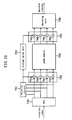
In addition, in viterbi decoding, there has been a
conventional technique for reducing power consumption in
the path memory. Figure 16 shows a conventional viterbi
decoder with a structure to reduce power consumption in
the path memory (disclosed in Japanese Laid-Open Patent
Application No. 8-46524). To simplify the explanation,
this drawing indicates the case where the encoding rate is
1/2 and the constraint length (the number of shift
registers contained in a convolutional encoder + 1) K=3.
-
In Figure 16, an ACS (Add Compare Select) circuit 700
generates path select signals from reception codes entered
therein. A majority circuit 701 outputs "0" when there
are more "0"s than "1"s in the 4-bit path select signals
outputted from the ACS circuit 700, and outputs "1" when
there are more "1"s than "0"s. A first conversion unit
702 includes means 702a to 702d each for generating an XOR
of an output of the ACS circuit 700 and the corresponding
output of the majority circuit 701. Receiving "1" as the
output of the majority circuit 701, the means 702a to 702d
reverse the path select signals received from the ACS
circuit 700. The outputs of the majority circuit 701 are
also stored in a storage delay unit 703.
-
The storage delay unit 703 delays the outputs of the
majority circuit 701 by the length of the delay in
decoding, and outputs them at the same timing as the
corresponding path select signals are outputted from the
path memory 704. A second conversion unit 705 includes
means 705a to 705d each for generating an XOR of an output
of the path memory 704 and the corresponding output of the
storage delay unit 703. When the output of the storage
delay unit 703 is "1", the means 705a to 705d reverse the
path select signals outputted from the path memory 704 so
as to return the path select signals to their original
states.
-
Through these operations, the path select signals
stored in the path memory 704 are supposed to have more
logical value "0"s than "1"s. Consequently, the signal
transition in the path memory 704 occurs less frequent so
as to reduce power consumption, thereby achieving a
viterbi decoder operative with lower power consumption.
PROBLEMS TO BE SOLVED
-
However, the above-mentioned conventional structure
requires a majority circuit, a storage delay unit and
conversion units as add-on circuits for an intrinsic
viterbi decoder. This undesirably increases the circuit
size, thereby boosting the power consumption in the large
add-on circuits when the constraint length becomes large
or when a delay in decoding is extended in order to
improve the ability to correct errors.
-
Moreover, a majority circuit usually operates slower
as the number of target bits increases, so that the above-mentioned
conventional structure is not suitable for a
viterbi decoder, which requires high-speed operations.
DISCLOSURE OF THE INVENTION
-
The present invention has an object of reducing power
consumption in the-path storage means for storing path
select signals in viterbi decoding in a different manner
from conventional methods.
-
To be more specific, the present invention relates to
a viterbi decoder and a viterbi decoding method for
performing decoding by using path storage means for
storing path select signals, performing the steps of:
partially tracing back path select signals outputted from
ACS means between a first time point and a second time
point, thereby finding surviving paths reaching each node
at the first time point; detecting a non-passing node
through which said surviving paths do not pass, of nodes
at the second time point; converting a path select signal
corresponding to said non-passing node at the second time
point in such a manner as to decrease a probability of
occurrence of a signal transition in said path storage
means; and storing path select signals corresponding to
said nodes at the second time point to said path storage
means.
-
According to the present invention, a path select
signal which is never referred to in a trace back for
decoding and which corresponds to a non-passing node is so
converted as to decrease the probability of occurrence of
a signal transition in the path storage means. The
decrease in the probability of occurrence of a signal
transition in the path storage means results in a
reduction in power consumption.
-
In the viterbi decoder and viterbi decoding method, it
is preferable that said path select signal corresponding
to said non-passing node is converted into a predetermined
fixed value which is one of signal values of said path
select signal. Consequently, the path storage means
statistically contains the logical value corresponding to
the predetermined fixed value more than the other logical
value, thereby making the dispersion of logical value
uneven. As a result, the probability of occurrence of a
signal transition in the path storage means becomes lower
than in the case where no conversion is performed, thereby
restricting power consumption in the path storage means.
-
In the viterbi decoder and viterbi decoding method, it
is preferable that said path select signal corresponding
to said non-passing node is converted into a same value as
a value already stored in a storage region in said path
storage means where said path select signal to be
converted is supposed to be written. Consequently, the
probability of occurrence of a signal transition in the
path storage means becomes lower than in the case where no
conversion is performed, thereby restricting power
consumption in the path storage means.
-
The present invention also relates to a viterbi
decoder which has path storage means for storing path
select signals and which performs decoding by using said
path storage means, said viterbi decoder comprising: a
path temporary storage unit for storing path select
signals outputted from ACS means over a certain period of
time and then outputting said path select signals; a
partial trace back unit for tracing back surviving paths
reaching each node at time t+p by using path select
signals between time t and time t+p-1 where p is a natural
number which are stored in said path temporary storage
unit and path select signals at time t+p outputted from
said ACS means so as to detect a non-passing node through
which said surviving paths do not pass; and a conversion
unit for inputting path select signals at time t outputted
from said path temporary storage unit, and receiving
signals from said partial trace back unit so as to convert
a path select signal corresponding to said non-passing
node out of said path select signals at time t into a
predetermined fixed value which is one of signal values of
said path select signal, said path storage means storing
path select signals at time t outputted from said
conversion unit.
-
Alternatively, the present invention relates to a
viterbi decoder which has path storage means for storing
path select signals and which perform decoding by using
said path storage means, said viterbi decoder comprising:
a path temporary storage unit for storing path select
signals outputted from ACS means over a certain period of
time and then outputting said path select signals; a
partial trace back unit for tracing back surviving paths
reaching each node at time t+p by using path select
signals between time t and time t+p-1 where p is a natural
number which are stored in said path temporary storage
unit and path select signals at time t+p outputted from
said ACS means so as to detect a non-passing node through
which said surviving paths do not pass; readout means for
reading out storage contents in a storage region in said
path storage means where path select signals at time t are
supposed to be written; and a conversion unit for
inputting said path select signals at time t outputted
from said path temporary storage unit and said storage
contents outputted from said readout means and receiving
signals from said partial trace back unit so as to convert
a path select signal corresponding to said non-passing
node out of said path select signals at time t into a same
value as a value which is contained in said storage
contents and stored in a storage region where said path
select signal to be converted is supposed to be written,
said path storage means storing path select signals at
time t outputted from said conversion unit.
-
It is preferable that said partial trace back unit
finds a function g (t, j) concerning each node j at time t,
and determines that node j is a non-passing node when g (t,
j)=0, where g (t, i) is a function for calculating g (r,
i)=Σ{g (r+1, n (i))×f (r, n (i))} from r=t+p-1 until r=t
in sequence by using g (t+p, k)=1 as an initial value
where k is an any node number, where
n (i): transition target nodes at time r+1 of a node i
at time r;
f (r, n (i)): a function which indicates whether or
not surviving paths reaching nodes n (i) at time r+1 pass
through node i at time r, and which becomes "1" when said
surviving paths pass through said nodes i, "0" otherwise;
Σ{}: an OR of all said nodes n (i); and
×: AND.
-
This indicates that the partial trace back unit is
realized by a small-sized circuit, based on the nature of
calculation. In other words, according to the present
invention, detection of a non-passing node is executed by
repetitive calculations of simple ANDs and ORs, making it
possible to construct the partial trace back unit by a
small-sized calculator.
-
It is further preferable that said partial trace back
unit comprises a plurality of storage means for storing
each value of g (r, i) at time r, and performs calculation
of said function g (t, j) by pipeline processing.
Consequently, the calculation of g (t, j) can be executed
by being divided into a plurality of cycles. As a result,
the amount of calculation per cycle can be lessened,
thereby realizing a high-speed detection of a non-passing
node.
-
The present invention relates to a viterbi
decoder and a viterbi decoding method for performing
decoding by using path storage means, performing the steps
of: applying predetermined conversion to path select
signals outputted from ACS means; storing converted path
select signals in said path storage means; applying
conversion reverse to said predetermined conversion to
path select signals outputted from said path storage
means; and performing decoding by using reversely-converted
path select signals, said predetermined
conversion being so conducted that, out of combinations of
path select signals representing surviving paths in a
predetermined portion in a trellis diagram, a first
combination with a relatively high frequency of occurrence
contains a predetermined fixed value which is one of
signal values of said path select signals more than a
second combination with a relatively low frequency of
occurrence.
-
According to the present invention, before being
stored in the path storage means, the path select signals
outputted from the ACS means are so converted that the
combination with a relatively high frequency of occurrence
has the predetermined fixed value which is one of the
signal values of the path select signals more than the
combination with a relatively low frequency of occurrence.
Consequently, the path storage means statistically
contains the logical value corresponding to the
predetermined fixed value more than the other value,
thereby making the dispersion of logical value uneven. As
a result, the probability of occurrence of a signal
transition in the path storage means becomes lower than in
the case where no conversion is performed, thereby
restricting power consumption in the path storage means.
-
It is preferable that said predetermined conversion is
performed by using a combination of path select signals
with a relatively few number of merges of surviving paths
as the first combination, and a combination of path select
signals with a relatively large number of merges of
surviving paths as the second combination.
BRIEF DESCRIPTION OF THE DRAWINGS
-
- Figure 1 shows the structure of the viterbi decoder of
the first embodiment of the present invention.
- Figure 2 shows the internal structure of the partial
trace back unit of Figure 1.
- Figures 3A to 3E show the behavior of the viterbi
decoder of Figure 1; Figure 3A shows a part of the trellis
diagram between time t and time t+1, and Figures 3B to 3E
respectively show the surviving paths in the trellis
diagram of Figure 3A.
- Figure 4 is a simplified trellis diagram starting from
a node j at time t to time t+p.
- Figure 5 shows the logic circuit which generates mask
signals that is structured in accordance with the partial
trellis of Figure 3A.
- Figure 6 shows the structure of the viterbi decoder of
the first embodiment of the present invention in the case
where p=2.
- Figures 7A to 7C are diagrams explaining the structure
and principle of operation of the partial trace back of
Figure 6; Figure 7A shows apart of the trellis diagram
between time t and time t+2, Figure 7B shows a logic
circuit which generates mask signals that is structured in
accordance with the partial trellis of Figure 7A, and
Figure 7C shows the paths related to the node j at time t
in the partial trellis of Figure 7A.
- Figure 8 shows the structure of the viterbi decoder of
a modified example of the first embodiment of the present
invention.
- Figure 9 shows a modified example of the viterbi
decoder of Figure 6 where the partial trace back unit
performs pipeline processing.
- Figure 10 is a timing chart depicting the behavior of
the viterbi decoder of Figure 9.
- Figure 11 shows the structure of the viterbi decoder
of the second and fourth embodiments of the present
invention.
- Figure 12 is a flowchart depicting the viterbi
decoding method of the second embodiment of the present
invention.
- Figure 13 shows the structure of the viterbi decoder
of the third embodiment of the present invention.
- Figures 14A to 14D are diagrams explaining the
behavior of the viterbi decoder of Figure 13, and
respectively show the surviving paths and the combinations
of path select signals in the partial trellis between time
t and time t+1.
- Figure 15 is a flowchart depicting the viterbi
decoding method of the fourth embodiment of the present
invention.
- Figure 16 shows the structure of a conventional
viterbi decoder.
-
BEST MODE FOR CARRYING OUT THE INVENTION
-
The embodiments of the present invention will be
described as follows with reference to the drawings. In
the following description, a node having a node number j
(j is either 0 or a positive integer) in the trellis
diagram will be referred to as a node j.
(EMBODIMENT 1)
-
Figure 1 shows the rough structure of the viterbi
decoder of the first embodiment of the present invention.
In order to simplify the explanation, the following
description will show the case where the encoding rate is
1/2 and the constraint length K=3. Furthermore, "j" is
expressed in j=2*s0+s1 by 2-bit data s0 and s1 stored in a
shift resister indicating the state of the encoder.
-
In Figure 1, the viterbi decoder comprises an ACS
circuit 100 as ACS (Add Compare Select) means for
generating path select signals from reception codes, a
path temporary storage unit 101 which stores path select
signals outputted from the ACS circuit 100 over a
predetermined period of time and then outputs them, and a
partial trace back unit 102 which traces back surviving
paths reaching each node at time t+p by using the path
select signals of between time t and time t+p-1 (p is a
natural number) stored in the path temporary storage unit
101 and the path select signals at time t+p outputted from
the ACS circuit 100, and detects a non-passing node,
through which the surviving paths do not pass, from among
the nodes at time t.
-
Here, assume that p=1. In other words, the path
temporary storage unit 101 stores path select signals for
one time point. The partial trace back unit 102 outputs,
as a mask signal MSKt, "0" for the path select signal
corresponding to the non-passing node, of the path select
signals PSt at time t outputted from the path temporary
storage unit 101, and further outputs "1" for the path
select signal corresponding to the node other than the
non-passing node, or to the node through which the
surviving path passes.
-
The viterbi decoder further comprises a conversion
unit 103 which inputs the path select signals PSt from the
path temporary storage unit 101 and receives the mask
signals MSKt from the partial trace back unit 102 so as to
convert, of the path select signals PSt, the path select
signal corresponding to the non-passing node into the
logical value "0" as the predetermined fixed value. The
conversion unit 103 includes AND generation means 103a to
103d for generating and outputting the AND of each bit of
the path select signals PSt outputted from the path
temporary storage unit 101 and the corresponding bit of
the mask signals MSKt, respectively.
-
The viterbi decoder further comprises a path memory
104 as path storage means for storing the path select
signals outputted from the conversion unit 103 and a
decoding unit 105 for generating and outputting decoded
signals by tracing back the path select signals stored in
the path memory 104.
-
Figure 2 shows the internal structure of the partial
trace back unit 102 of Figure 1. As shown in the
structure, the partial trace back unit 102 receives the
path select signals PSt+1 at time t+1 and in turn outputs
the mask signals MSKt for the path select signals PSt at
time t.
-
The behavior of the viterbi decoder thus structured
will be described as follows with reference to Figures 3A
to 3E.
-
Figure 3A shows the partial trellis which is a part of
the trellis diagram between time t and time t+1. By
giving "0" and "1" to the data s0, the trellis diagram
between time t and time t+1 of the present embodiment is
obtained. As shown in Figure 3A, the ACS circuit 100
outputs "0"s as the path select signals PSt+1 when it
selects a transition from the node 2*s0 at time t, and
outputs "1"s when it selects a transition from the node
2*s0+1 for the nodes s0 and s0+2 at time t+1 from the
reception signals at time t+1.
-
In this case, the possible combinations of the
surviving paths between time t and time t+1 are shown in
Figures 3B to 3E. In Figures 3B to 3E, the path select
signals PSt+1 (s0) and PSt+1 (s0+2) for the nodes s0 and
s0+2 at time t+1 become (0, 0), (1, 1), (0, 1), and (1, 0),
respectively.
-
It must be noted that when the surviving paths merge
with each other as in Figures 3B and 3C, no path passes
through the node 2*s0+1 in Figure 3B or the node 2*s0 in
Figure 3C at time t in tracing back from time t+1. Thus,
in tracing further back from time t, path select signals
corresponding to these nodes are never referred to. In
other words, whatever value the value of the path select
signal corresponding to non-passing node through which no
surviving path passes may be converted into, it does not
badly affect the decoding operation. The present
invention has been contrived based on these findings.
-
To be more specific, detecting the state shown in
either Figure 3B or Figure 3C from the path select signals
PSt+1 at time t+1, the partial trace back unit 102
generates "0" as a mask signal MSKt for the path select
signal corresponding to the non-passing node through which
the surviving paths do not pass, and further generates
"1"s as the mask signals MSKt for the other path select
signals out of the path select signals PSt at time t
stored in the path temporary storage unit 101.
-
For example, assume that the data s0=0, the state of
Figure 3B will be:
PSt+1 (0)=0, PSt+1 (2)=0
-
In this case, the non-passing node is node 1. In the
structure of Figure 2, under conditions of Formula (1),
only MSKt (1) becomes "0". The state of Figure 3C will
be:
PSt+1 (0)=1, PSt+1 (2)=1
-
In this case, the non-passing node is node 0. In the
structure of Figure 2, under conditions of Formula (2),
only MSKt (0) becomes "0".
-
The conversion unit 103 makes the AND generation means
103a to 103d AND the path select signal corresponding to
the non-passing node with the mask signal MSKt or "0" so
as to convert the path select signal corresponding to the
non-passing node into "0". The path select signals
corresponding to the nodes other than the non-passing node
are not converted because the mask signals MSKt are "1"s.
-
The path memory 104 stores the outputs of the
conversion unit 103. The decoding unit 105 performs
tracing back in the traditional manner using the path
select signals stored in the path memory 104 so as to
decode these signals.
-
Through the above-mentioned structure and behavior,
the path select signal corresponding to the non-passing
node is converted into "0" and stored in the path memory
104, so that the values of the path select signals stored
in the path memory 104 statistically have more "0"s than
"1"s. As a result, the probability of occurrence of a
signal transition in the memory cell or memory output of
the path memory 104 becomes lower than 1/2. This reduces
power consumption in the path memory 104, thereby
realizing a viterbi decoder operative with low power
consumption.
-
Unlike the conventional structure, the decoder of the
present embodiment has the partial trace back unit 102
smaller in size than the majority circuit 701, so that its
add-on circuits can be far smaller in size than the
conventional ones and does not need the storage delay unit
703 or the second conversion unit 705.
-
In the structure shown in Figure 1, the path select
signals that have not been converted yet are used for
decoding because if converted path select signals were set
at the start of tracing back, it might cause the wrong
path to be traced back.
-
The above description shows the case where the
encoding rate is 1/2, the constraint length K=3, and p=1;
however, in general when the encoding rate is m/n (n and m
are positive integers), the partial trellis can be
extended from between 2 states shown in Figure 3A to
between 2m states. This makes it possible to trace back
the surviving paths from each state at time t+1, and to
covert the path select signals corresponding to the states
at time t when not a single surviving path passes through
to "0"s. As a result, the same effects as the present
embodiment can be obtained.
<Generalization of partial trace back>
-
The convolutional codes having an encoding rate of m/n
on Galois field (q) (q is a prime number, and m and n are
natural numbers) are characterized by the trellis diagram
having the state transition of the encoder extended in the
direction of time.
-
Figure 4 shows a simplified trellis diagram starting
from a node j at time t to time t+p. There are qm paths
which make a transition from a node i at time r to the
next time point r+1, and there are also qm transition
target nodes n (i). With respect to these transition
target nodes n (i), a function f (r, n (i)) is defined as
follows. When surviving paths reaching the nodes n (i) at
time r+1 pass through the node i at time r, the following
equation holds:
f (r, n (i))=1.
-
On the other hand, when the surviving paths pass
through a node other than the node i, the following
equation holds:
f (r, n (i))=0.
-
With respect to the nodes n (i) at time r+1, a
function g (r+1, n (i)) is defined as follows. When at
least one of the surviving paths from time t+p passes
through the nodes n (i), the following equation holds:
g (r+1, n (i))=1.
-
When not a single surviving path passes through the
nodes n (i), the following equation holds:
g (r+1, n (i))=0.
-
If the value of g (t+p, k) for all the nodes at time
t+p is "1", then g (r, i) can be easily found by
calculating Formula (3) below from time t+p to time r in
sequence:
g (r, i)=Σ{g (r+1, n (i))×f (r, n(i))}
where Σ{·} indicates the OR of {·} concerning all of
the qm nodes n (i), and × indicates the AND of the same.
-
Consequently, g (t, j) becomes "1" when at least one
of the surviving paths at time t+p passes through the node
j at time t, "0" otherwise. As a result, a node j which
makes g (t, j)=1 becomes a passing node, and a node j
which makes g (t, j)=0 becomes a non-passing node.
-
Thus, the partial trace back unit can determine that a
node j becomes a non-passing node when g (t, j)=0 through
a calculation of g (r, i) in Formula (3) from r=t+p-1 to
r=t in sequence by using g (t+p, k)=1 (k can be any node
number) as the initial value. The value of g (t, j) can
be used as the mask signals MSKt (j).
-
In the above example, since m=1, p=1 and the
constraint length K=3 makes the number of states 4 (=2(3-1)),
the trellis diagram treated by the partial trace back unit
102 can be divided into partial trellis between 2 states
as shown in Figure 3A.
-
Furthermore, p=1 leads to g (t+1, k)=1, and Formula
(3) becomes a simple OR of f (t, n (i)). In this case, f
(t, n (2*s0)) is equal to the logical inverse of the path
select signals PSt+1 (s0) and PSt+1 (s0+2) at time t+1 ,
and f (t, n (2*s0+1)) becomes equal to the path select
signals PSt+1 (s0) and PSt+1 (s0+2) at time t+1. To be
more specific.
g (t, 2*s0)=Σ{f (t, n (2*s0))}
=!PSt+1 (s0)+!PSt+1 (s0+2)
g (t, 2*s0+1)=Σ{f (t, n (2*s0+1))}
=PSt+1 (s0)+PSt+1 (s0+2)
where ! represents logical inverse.
-
Consequently, the partial trace back unit 102 can be
composed of the logical circuit shown in Figure 5. The
partial trace back unit 102 shown in Figure 2 can be
obtained by providing the logical circuit of Figure 5 with
s0="0" and "1".
-
The same holds true when p is 2 or larger. In that
case, the path temporary storage unit 101 stores p sets of
path select signals between time t and time t+p-1. In
order to determine a non-passing node, the partial trace
back unit 102 needs to receive path select signals of q (k-1)
· m · (p-1) bits (q states per bit) where q (k-1) is equal
to the number of states the encoder can take.
<When p=2>
-
In order to simplify the explanation, the following
description will show the case where the encoding rate is
1/2, the constraint length K=3, p=2, and q=2.
-
Figure 6 shows the entire structure of the viterbi
decoder of the present embodiment where p=2. Its
fundamental structure is the same as the case of p=1, so
that the structural elements operating the same manner as
the case of p=1 will not be described in detail.
-
Since it is composed of a shift register and p=2, the
path temporary storage unit 110 stores path select signals
at time t and time t+1. The partial trace back unit 120
receives the path select signals PSt+1 at time t+1 stored
in the path temporary storage unit 110 and the path select
signals PSt+2 at time t+2 outputted from the ACS circuit
100, and calculates and outputs the mask signals MSKt for
the conversion of the path select signals PSt at time t.
The conversion unit 103 converts the path select signals
PSt at time t outputted from the path temporary storage
unit 110 by using the mask signals MSKt outputted from the
partial trace back unit 120 and stores the converted
signals in the path memory 104.
-
By referring to Figures 7A to 7C, the detailed
structure and principle of operation of the partial trace
back unit 120 shown in Figure 6 will be described as
follows.
-
The trellis diagram between time t and time t+2
appears as shown in Figure 7A. The nodes n (i) which make
a transition from the node i are as follows:
n (0)={0, 2}
n (1)={0, 2}
n (2)={1, 3}
n (3)={1, 3}
-
Since the ACS circuit 100 operates the same manner as
the case of p=1, f (r, n (i)) of each node i at time r
becomes as follows by using the path select signals PSr+1
(n (i)) at time r+1:
f (r, n (0))=!PSr+1 (n (0))
f (r, n (1))=PSr+1 (n (1))
f (r, n (2))=!PSr+1 (n (2))
f (r, n (3))=PSr+1 (n (3))
where ! represents logical inverse.
-
From Formula (3), if the initial value g (t+2, k)=1
(k=0, 1, 2, 3), then,
g (t+1, 0)=Σ {g (t+2, n (0))×f (t+1, n (0))}
=g (t+2, 0)×(!PSt+2 (0))
+g (t+2, 2)×(!PSt+2 (2))
=!PSt+2 (0)+!PSt+2 (2)
-
Similarly,
g (t+1, 1)=PSt+2 (0)+PSt+2 (2)
g (t+1, 2)=!PSt+2 (1)+!PSt+2 (3)
g (t+1, 3)=PSt+2 (1)+PSt+2 (3)
-
As a result,
g (t, 0)=Σ {g (t+1, n (0))×f (t, n (0))}
=g (t+1, 0)×(!PSt+1 (0))
+g (t+1, 2)×(!PSt+1 (2))
=(!PSt+2 (0)+!PSt+2 (2))X(!PSt+1 (0))
+(!PSt+2 (1)+!PSt+2 (3))×(!PSt+1 (2))
-
Similarly,
g (t, 1)=(!PSt+2 (0)+!PSt+2 (2))×(PSt+1 (0))
+(!PSt+2 (1)+!PSt+2 (3))×(PSt+1 (2))
g (t, 2)=(PSt+2 (0)+PSt+2 (2))×(!PSt+1 (1))
+(PSt+2 (1)+PSt+2 (3))×(!PSt+1 (3))
g (t, 3)=(PSt+2 (0)+PSt+2 (2))×(PSt+1 (1))
+(PSt+2 (1)+PSt+2 (3))×(PSt+1 (3))
-
These equations indicate that g (t, i) can be found by
simple ORs and ANDs of the path select signals PSt+2 at
time t+2 and the path select signals PSt+1 at time t+1.
The calculation of these equations can be realized by the
logical circuit shown in Figure 7B, which is similar to
the internal structure of the partial trace back unit 120
of Figure 6.
-
The above-mentioned function g (t, i) indicates
whether or not there are any surviving path among the four
paths extending from the node i at time t to time t+2.
For example, g (t, 1) indicates whether or not there is
any surviving path among the four paths extending from
node 1 at time t to time t+2 shown in Figure 7C. When the
path extending between the node 0 at time t+1 and the node
0 at time t+2 is a surviving path, the values of the path
select signals PSt+1 (0) and PSt+2 (0) become (1, 0). In
this case, g (t, 1)=1. Similarly, when any of the other
three paths is a surviving path, g (t, 1)=1 is obtained.
-
As described above, when p=2, there are substantially
more non-passing nodes than in the case of p=1, so that
more path select signals are converted into the
predetermined fixed value than in the case of p=1. As a
result, the path memory 104 has more signal value "0"s,
thereby further reducing the probability of occurrence of
a signal transition. As a result, a reduction in power
consumption can be more remarkable.
-
Generally, tracing back with a length several times as
large as the constraint length makes all surviving paths
merge together, so that it is preferable that the value of
p is at most several times as large as the constraint
length. Although an increase in the value of p decreases
power consumption in the path memory, it grows the partial
trace back unit and the path temporary storage unit in
size, thereby increasing their power consumption.
Therefore, the realistic value of p is generally 1 to 3.
-
In the present embodiment, the path select signal
corresponding to a non-passing node is converted into a
logical value "0". Alternatively, the signal could be
converted into a logical value "1" so that the signal
values stored in the path memory statistically have more
"1"s than "0"s, thereby obtaining the same effects as the
present embodiment. In that case, the AND generation
means 103a to 103d in the conversion unit 103 could be
replaced by OR generation means, and the partial trace
back unit 102 could output a logical value "1" for the
path select signal corresponding to the non-passing node
as the mask signal MSK and logical value "0"s for the
other path select signals.
(MODIFIED EXAMPLE 1)
-
In the above-mentioned embodiment, the path select
signal corresponding to a non-passing node is converted
into the predetermined fixed value by the mask signals
outputted from the partial trace back unit. Instead, the
path select signal corresponding to the non-passing node
can be converted into the same value as the one previously
stored in the storage region within the path memory where
the path select signal is supposed to be written, thereby
more directly reducing the occurrence of a signal
transition within the path memory.
-
Figure 8 shows the structure of the viterbi decoder of
the first modified example of the first embodiment. In
Figure 8, a readout unit 140 has a function of reading
path select signals already stored in the storage region
within the path memory 104 before the path select signals
outputted from the conversion unit 130 are written in the
storage region. Each selection means 130a to 130d in the
conversion unit 130 outputs a path select signal PSt
outputted from the path temporary storage unit 101 as it
is when the corresponding mask signal MSKt has a bit "1".
On the other hand, when the corresponding mask signal MSKt
has a bit "0", each selects and outputs the previous path
select signal already stored in the storage region where
the path select signal outputted from the readout unit 140
is supposed to be written.
-
The path select signal corresponding to a non-passing
node is thus converted into the same value as the one
already stored in the storage region within the path
memory 104 where the path select signal is supposed to be
written, so that storing the converted path select signals
does not cause a signal transition within the path memory.
As a result, the probability of occurrence of a signal
transition in the path memory 104 is reduced, which leads
to a decrease in power consumption.
(MODIFIED EXAMPLE 2)
-
In the structure shown in Figure 6, the partial trace
back unit 120 finds each of the mask signals MSKt, or g (t,
i) from the path select signals PSt+2 and PSt+1 at the
same time. However, these path select signals PSt+2 and
PSt+1 are generated every input cycle of reception codes,
so that executing the calculation of g (t, i) by being
divided into a plurality of steps can reduce the amount of
calculation per step. As a result, a high-speed decoding
operation can be achieved.
-
Figure 9 shows the structure of the viterbi decoder of
the second modified example of the first embodiment. The
partial trace back unit 120A in Figure 9 performs the
calculation of g (t, j) by pipeline processing, and
differs from the partial trace back unit 120 shown in
Figure 6 in having storage means 121 and 122 for storing g
(t+1, i) and g (t, i)(i=0, 1, 2, 3), respectively. The
viterbi decoder further comprises delay means 123 and 124
for compensating a delay before the calculation of the
mask signals MSKt.
-
As shown in Figure 10, when the ACS circuit 100
sequentially outputs the path select signals PSt, PSt+1,
PSt+2 and so on in accordance with the cycle of the
reception codes, the register FF1 of the path temporary
storage unit 110 outputs a path select signal delayed by 1
cycle, and the register FF2 outputs a path select signal
delayed by 2 cycles. At time t+2, a first calculation
unit 131 of the partial trace back unit 120A calculates g
(t+1, i) by using the output PSt+2 of the ACS circuit 100
and stores the result in the storage means 121. At time
t+3, a second calculation unit 132 of the partial trace
back unit 120A calculates g (t, i) by using the output g
(t+1, i) of the storage means 121 and the output PSt+1 of
the delay means 123, and stores the result in the storage
means 122.
-
At time t+4, the storage means 122 of the partial
trace back unit 120A outputs g (t, i) as a mask signal MSK.
The delay means 124 delays the outputs PSt of the path
temporary storage unit 110 until time t+4. The conversion
unit 103 performs the same operation as in the first
embodiment to the outputs of the delay means 124 by using
the mask signals MSK outputted from the partial trace back
unit 120A.
-
This structure makes the mask signals MSK or g (t, i)
be calculated in a span of time corresponding to 2 cycles
of the reception codes, thereby realizing a higher-speed
calculation than in the structure shown in Figure 6 where
the calculation is performed in 1 cycle. It goes without
saying that when p is 3 or larger, pipeline processing can
be performed in the same manner as the present modified
example.
(EMBODIMENT 2)
-
The second embodiment of the present invention
achieves the same process as the viterbi decoder of the
first embodiment in terms of software.
-
Figure 11 shows the rough structure of the viterbi
decoder of the present embodiment. This decoder comprises
an arithmetic logical calculator 201 (ALU), a multiplier
202 (MUL), a ROM 203 for storing instructions to execute
viterbi decoding of the present embodiment, a RAM 204 as
path storage means, and a general-purpose register 205.
These units 201 to 205 are connected via a bus 206.
-
Figure 12 is a flowchart showing the viterbi decoding
method executed in the viterbi decoder shown in Figure 11.
The viterbi decoding method of the present embodiment will
be described as follows with reference to Figure 12. In
order to simplify the explanation, the following
description will show the case where the encoding rate is
1/2, the constraint length K=3, and p=1.
-
As shown in Figure 12, at Step S11, each branch metric
is generated from reception signals stored in the RAM 204,
and paths are selected so as to generate path select
signals. These calculations are performed by the ALU 201
and the MUL 202. At Step S12, the path select signals are
temporary stored in the general-purpose register 205.
-
Then, Step S13 is executed. First, variable i is
initialized to "0", and then the paths of a node i are
traced back so as to store the numbers of the passing
nodes at one time point earlier as starting nodes in the
general-purpose register 205. After adding "1" to the
variable i, tracing back and storing of the starting nodes
are performed in the same manner. When i>3, Step S13 is
terminated. As a result, the starting nodes of the paths
at all the nodes 0, 1, 2 and 3 are stored in the general-purpose
register 205.
-
Then, Step S14 is executed. After initializing the
variable i to "0", it is checked whether the node number i
exists in the numbers of the starting nodes detected and
stored in the general-purpose register 205 at Step S13.
When the number does not exist, the bit of the path select
signal at the time point corresponding to the node i
stored in the general-purpose register 205 is converted
into "0". After this, "1" is added to the variable i to
perform the same process. When i>3, Step S14 is
terminated. Thus, all the nodes have been checked whether
they are non-passing nodes or not, and the path select
signal corresponding to a non-passing node is converted
into the fixed value "0".
-
At Step S15, the path select signals converted at Step
S14 are stored in the RAM 204. At Step S16, the most
probable surviving path is traced back for the truncation
length to obtain a decoded signal. The series of steps
are executed by an execution program stored in the ROM 203.
-
As described hereinbefore, according to the present
embodiment, the path select signals which do not affect
the decoding process at Step S16 are converted into the
fixed value "0"s at Step S14. Consequently, the logical
values of the path select signals stored in the RAM 204
statistically have more "0"s than "1"s, thereby making the
probability of occurrence of a signal transition in the
RAM 204 lower than 1/2. As a result, power consumption in
the RAM 204 can be reduced without deteriorating decoding
performance at all.
-
The present embodiment describes about the case where
the encoding rate is 1/2, K=3, and p=1; however, the same
effects can be obtained in the case where the partial
trellis is extended from between 2 states to between 2m
states when the encoding rate is m/n (n and m are positive
integers). In addition, the similar effects can be
obtained when p is 2 or larger as described in the first
embodiment.
-
In the present embodiment, the path select signal
corresponding to a non-passing node is converted into a
logical value "0". Instead, when the signal is converted
into a logical value "1", the signal values stored in the
RAM statistically have more "1"s than "0"s, thereby
achieving the same effects as in the present embodiment.
(EMBODIMENT 3)
-
Figure 13 shows the rough structure of the viterbi
decoder of the third embodiment of the present invention.
In order to simplify the explanation, the following
description will show the case where the encoding rate is
1/2 and the constraint length K=3.
-
The viterbi decoder shown in Figure 13 comprises an
ACS circuit as ACS means for generating path select
signals from the reception codes, a conversion unit 310
which applies predetermined conversion to path select
signals outputted from the ACS circuit 300, a path memory
as path storage means for storing the converted path
select signals outputted from the conversion unit 310, a
reverse conversion unit 330 which converts the path select
signals outputted from the path memory 320 reverse to the
predetermined conversion in the conversion unit 310, and a
decoding unit 340 which performs decoding by using the
reversely-converted path select signals outputted from the
reverse conversion unit 330.
-
The ACS circuit 300 outputs "0"s when it selects the
transition from the node 2*s0 at time t, and outputs "1"s
when it selects the transition from the node 2*s0+1 as the
path select signals for the nodes s0 and s0+2 (s0 is
either 0 or 1) at time t+1.
-
The conversion unit 310, to be more specific,
comprises logical inverse means 311a and 311b for
generating the logical inverse of the path select signals
for the node s0+2, and XOR generation means 312a and 312b
for generating the exclusive OR of the output of each of
the logical inverse means 311a and 311b, respectively, and
the respective path select signal for the node s0. The
reverse conversion unit 330, similar to the conversion
unit 310, comprises logical inverse means 331a and 331b
for generating the logical inverse of the path select
signals for the node s0+2, and XOR generation means 332a
and 332b for generating the exclusive OR of the output of
each of the logical inverse means 331a and 331b,
respectively, and the respective path select signal for
the node s0.
-
The behavior of the viterbi decoder thus structured
will be described as follows with reference to Figures 14A
to 14D.
-
There are four possible combinations of path select
signals indicating the surviving paths between the states
2*s0 and 2*s0+1 at time t and the states s0 and s0+2 at
time t+1 of the trellis diagram as shown in Figures 14A to
14D. In Figures 14A to 14D, the path select signals PSt+1
for the states s0 and s0+2 at time t+1 are (0, 0), (1, 1),
(0, 1) and (1, 0), respectively.
-
Of these combinations of the path select signals shown
in Figures 14A to 14D, the cases of Figures 14A and 14B
where the surviving paths merge with each other
statistically occur less frequently than the cases of
Figures 14C and 14D where the surviving paths do not merge.
In short, precision decoding requires a sufficiently long
trace back length. From this, it can be inferred that the
merging of paths does not occur so frequently and that the
probability of merging of paths at each time point is
lower than the probability of not merging. This agrees
with the empirical findings of the inventors of the
present invention through research and development.
-
Therefore, in the present embodiment, conversion of
path select signals is so performed that the combinations
of the path select signals shown in Figures 14C and 14D as
the first combination having a relatively high frequency
of occurrence have more logical value "0"s than the
combinations of the path select signals shown in Figures
14A and 14B as the second combination having a relatively
low frequency of occurrence.
-
To be more specific, the conversion unit 310 converts
the path select signal (1, 0) of Figure 14D into (0, 0),
and also converts the path select signal (0, 0) of Figure
14A into (1, 0). The path select signals outputted from
the conversion unit 310 are stored in the path memory 320.
The reverse conversion unit 330 converts the path select
signals (0, 0) and (1, 0) outputted from the path memory
320 into (1, 0) and (0, 0), respectively, reverse to the
conversion in the conversion unit 310.
-
Through the above-described structure and behavior,
the signal values of the path select signals stored in the
path memory 320 statistically have more "0"s than "1"s,
making the probability of occurrence of a signal
transition in the memory cell or memory output of the path
memory 320 lower than 1/2. As a result, power consumption
in the path memory 320 can be reduced, thereby realizing a
viterbi decoder operative with low power consumption.
-
As add-on circuits, only the conversion unit 310
composed of simple logical gates and the reverse
conversion unit 330 are required, so that the circuit size
can be remarkably reduced compared with the conventional
structure. Consequently, the conversion in the conversion
unit 310 and the reverse conversion in the reverse
conversion unit 330 become the same process, which makes
the conversion unit 310 and the reverse conversion unit
330 be realized in the same structure.
(EMBODIMENT 4)
-
The fourth embodiment of the present invention
achieves the same process as the viterbi decoding of the
third embodiment in terms of software.
-
Figure 15 is a flowchart showing the viterbi decoding
method of the present embodiment. The viterbi decoding
method of the present embodiment is executed by the above-described
viterbi decoder shown in Figure 11. In order to
simplify the explanation, the following description will
show the case where the encoding rate is 1/2 and the
constraint length K=3.
-
As shown in Figure 15, at Step S21, each branch metric
is generated from the reception signals stored in the RAM
204, and paths are selected so as to generate path select
signals. These calculations are performed by the ALU 201
and the MUL 202. At Step S22, the path select signals are
temporary stored in the general-purpose register 205.
-
Then, Step S23 is executed. First, variable s0 is
initialized to "0", and then 2-bit path representation bit
strings which are path select signals to represent
surviving paths of nodes {s0, s0+2} are read from the path
select signals stored in the general-purpose register 205.
The read path representation bit strings are subjected to
the same predetermined conversion as in the third
embodiment. For example, {0, 1}, {1, 0}, {0, D} and {1,
1} are converted into {0, 1}, {0, 0}, {1, 0} and {1, 1},
respectively. Then, the same process is executed by
setting the variable s0 at "1" so as to terminate Step S23.
At Step S24, the converted path select signals are stored
in the RAM 204 as the path storage means.
-
At Step S25, the path select signals read from the RAM
204 are subjected to conversion reverse to the
predetermined conversion of Step S23. To be more specific,
of the converted bit strings that have been read, {0, 1},
{0, 0}, {1, 0} and {1, 1} are converted into {0, 1}, {1,
0}, {0, 0} and {1, 1}, respectively. At Step S26, tracing
back is performed by using the reversely-converted path
select signals so as to obtain decoded signals.
-
In the same manner as in the third embodiment,
conversion of path select signals is so performed that the
combinations of path select signals shown in Figures 14C
and 14D having a fewer number of merges and a relatively
high frequency of occurrence have more logical value "0"s
than the combinations of path select signals shown in
Figures 14A and 14B having a larger number of merges and a
relatively low frequency of occurrence. Consequently, the
logical values of the path select signals stored in the
RAM 204 statistically have more "0"s than "1"s, making the
probability of occurrence of a signal transition in the
RAM 204 lower than 1/2. As a result, power consumption in
the RAM 204 can be reduced, thereby realizing a viterbi
decoder operative with low power consumption.
-
The conversion method shown in the third and fourth
embodiments is one example, and other methods could be
used as long as the combinations of path select signals
having a relatively high frequency of occurrence have more
logical value "0"s than the combinations of path select
signals having a relatively low frequency of occurrence.
-
The third and fourth embodiments describe the case
where the encoding rate is 1/2 and the constraint length
K=3; however, in general, in the case where the encoding
rate is m/n, when the number of states contained in the
predetermined portion of the trellis diagram is x, the
number of bits of the path select signals representing
this predetermined portion becomes (m*x). The larger
number of paths out of the x surviving paths merge, or the
more paths merges with each other, the lower the frequency
of occurrence of the combinations becomes. Therefore, it
goes without saying that by performing conversion in such
a manner that the combinations of path select signals with
a higher frequency of occurrence have more logical value
"0"s, the same effects as the third and fourth embodiments
can be obtained.
-
In the third and fourth embodiments, conversion is so
performed that the combinations of path select signals
with a high frequency of occurrence have more logical
value "0"s; however, instead, more logical value "1"s can
be contained so as to obtain the same effects as the
present embodiment.
-
The other causes than the number of merges of
surviving paths may cause a difference in the frequency of
occurrence of the combinations of path select signals, and
the present invention can be applied to theses cases.
-
For example, in the case of convolutional encoder, if
input is random, the frequency of appearance of each state
transition is statistically even. On the other hand, when
the input has certain statistics (in the case where outer
coding is performed to make either "0" or "1" consecutive
over a certain period of time, for example), the frequency
of appearance of each state transition is not
statistically even. In that case, similar to the third
and fourth embodiments, conversion of path select signals
is so performed that a specific logical value outnumbers
the other logical value in the combinations of path select
signals statistically having a high frequency of
occurrence. This decreases the probability of occurrence
of a signal transition in the path storage means.
-
As described hereinbefore, according to the present
invention, the path select signal which corresponds to a
non-passing node and is never referred to in tracing back
for decoding is converted in such a manner as to decrease
the probability of occurrence of a signal transition in
the path storage means, thereby reducing power consumption.
-
Moreover, in the present invention, conversion of path
select signals is so performed that the combinations of
path select signals with a relatively high frequency of
occurrence have a larger number of a predetermined fixed
value which is one of the signal values of the path select
signals. As a result, the path storage means
statistically has a larger number of the signal value
corresponding to this predetermined fixed value. This
decreases the probability of occurrence of a signal
transition in the path storage means than in the case
where no conversion is performed, thereby reducing power
consumption.