EP1316833A2 - Transmitted light/lighting device for microscopes - Google Patents
Transmitted light/lighting device for microscopes Download PDFInfo
- Publication number
- EP1316833A2 EP1316833A2 EP03004725A EP03004725A EP1316833A2 EP 1316833 A2 EP1316833 A2 EP 1316833A2 EP 03004725 A EP03004725 A EP 03004725A EP 03004725 A EP03004725 A EP 03004725A EP 1316833 A2 EP1316833 A2 EP 1316833A2
- Authority
- EP
- European Patent Office
- Prior art keywords
- led
- transmitted light
- leds
- light
- microscopes
- Prior art date
- Legal status (The legal status is an assumption and is not a legal conclusion. Google has not performed a legal analysis and makes no representation as to the accuracy of the status listed.)
- Granted
Links
Images
Classifications
-
- G—PHYSICS
- G02—OPTICS
- G02B—OPTICAL ELEMENTS, SYSTEMS OR APPARATUS
- G02B21/00—Microscopes
- G02B21/06—Means for illuminating specimens
-
- G—PHYSICS
- G02—OPTICS
- G02B—OPTICAL ELEMENTS, SYSTEMS OR APPARATUS
- G02B21/00—Microscopes
- G02B21/06—Means for illuminating specimens
- G02B21/08—Condensers
- G02B21/086—Condensers for transillumination only
Definitions
- LED lighting unit advantages are long Lifespan, minimal energy consumption, daylight-like color temperature, color temperature-independent brightness control and low Heat.
Abstract
Description
Beleuchtungsanordnungen an Mikroskopen haben einen relativ schlechten
Wirkungsgrad bei der Umsetzung von aufgenommener elektrischer Leistung in
nutzbare Lichtleistung und sie erzeugen störende Wärme.
Darüber hinaus werden bei aufrechten Stativen Bauräume benötigt, die
ergonomisch günstige Anordnungen des Mikroskoptisches verhindern.
Schliesslich sind die Lösungen bauteilaufwendig und damit teuer.
Beleuchtungseinrichtungen für Mikroskope mit LED's bzw. LCD's sind aus
DE 3108389A1, US 4852985,DE 3734691 C2, DE 19644662A1 bekannt.Illumination arrangements on microscopes have a relatively poor efficiency in converting the electrical power consumed into usable light output and they generate disruptive heat.
In addition, installation space is required for upright tripods that prevent ergonomically favorable arrangements of the microscope stage. After all, the solutions are complex and therefore expensive. Illumination devices for microscopes with LEDs or LCDs are known from DE 3108389A1, US 4852985, DE 3734691 C2, DE 19644662A1.
Die genannten Nachteile sollen durch eine LED-Beleuchtungseinheit - bestehend aus einer oder mehreren angeordneten LED's - beseitigt werden, die wahlweise netzabhängig oder durch Batterien betrieben werden.The disadvantages mentioned are said to be due to an LED lighting unit - consisting of one or more arranged LEDs - can be eliminated can be operated either depending on the network or on batteries.
Diese Aufgabe wird durch die Merkmale des unabhängigen Anspruchs gelöst. Bevorzugte Weiterbildungen sind Gegenstand der abhängigen Ansprüche.This object is solved by the features of the independent claim. Preferred developments are the subject of the dependent claims.
Die Erfindung und ihre Wirkungen und Vorteile werden nachstehend anhand einer schematischen Zeichnung erläutert.The invention and its effects and advantages are described below a schematic drawing explained.
In Fig. 1 ist unter einem durchsichtigen Mikroskoptisch 1, auf dem sich eine
Probe befindet, die durch ein nicht dargestelltes Objektiv betrachtet wird, eine
Beleuchtungseinheit, bestehend aus Kondensoroptik 2 und Aperturblende 3,
angeordnet, die weiteren Teile des Mikroskopstatives sind hier nicht dargestellt.In Fig. 1 is under a
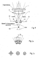
Zwei Weisslicht-LED's werden, wie im Bild 1 dargestellt, in der Nähe der
Apereturblendenebene angeordnet. Die LEDs werden über Leitungen 10 von
einer Stromversorgung 11 elektrisch versorgt. Two white light LEDs are, as shown in Figure 1, near the
Aperture aperture level arranged. The LEDs are on
Dabei können die Winkel zwischen den Mittenachsen der LED und/ oder deren
Abstand zur optischen Achse verändert werden.
Hierzu sind die LED senkrecht zur optischen Achse, wie durch die Pfeile
angedeutet, verschiebbar oder um eine Drehachse A2 senkrecht zur
Zeichenebene schwenkbar.The angles between the center axes of the LED and / or their distance from the optical axis can be changed.
For this purpose, the LEDs can be displaced perpendicular to the optical axis, as indicated by the arrows, or pivoted about an axis of rotation A2 perpendicular to the plane of the drawing.
Diese Anordnung der LEDs kann vorteilhaft zur Realisierung des Raumbildverfahrens mit getakteter Beleuchtung verwendet werden, wie es von der Anmelderin in EP 730 181, auf deren kompletten Inhalt hiermit Bezug genommen wird, vorgeschlagen wurde.This arrangement of the LEDs can be advantageous for realizing the Spatial imaging with clocked lighting can be used as it is by the applicant in EP 730 181, to the entire contents of which reference is hereby made is proposed.
Der Strahlenfluss der zeitlich über ihre Stromversorgung mit einem Beobachtungsshutter getakteten LED's wird mit den für eine Raumbilderzeugung durch die Beleuchtung notwendigen Winkeln in Richtung des Kondensors reflektiert.The flow of rays over time with their power supply Observation shutter clocked LEDs are used for one Spatial imaging by lighting necessary angles in the direction reflected by the condenser.
Mit zur Beobachtung getakteter Beleuchtung ändert sich auf diese Weise der Beleuchtungswinkel und damit ist die Basis für die räumliche Betrachtung einstellbar.The lighting changes in this way with the clocking for observation Illumination angle and thus is the basis for spatial observation adjustable.
In Fig. 2 ist dargestellt, wie mehrere Weisslicht-LED's zu einer gemeinsamen Strahlungsquelle zusammengefasst werden können.In Fig. 2 it is shown how several white light LEDs to a common Radiation source can be summarized.
Hierzu sind die LED's so angeordnet, dass sich die Tangenten ihrer
Abstrahlkegel berühren (Fig. 2a), indem der Winkel zwischen den Mittenachsen
ihrer Abstrahlkegel im Wesentlichen mit dem Winkel des Abstrahlkegels
übereinstimmt.
Über das flächenhafte Parallelschalten einzelner LED's in verschiedenen
Anordnungen wie in Fig. 2b dargestellt, kann eine größere strahlende Fläche mit
dem gleichen Divergenzwinkel wie der einer einzelnen LED angeboten werden.
Durch das gerichtete Verkippen u. straussförmige Zusammenfassen der
einzelnen LED's in der Weise, dass sich die Tangenten der Abstrahlkegel
berühren, werden sowohl eine größere Fläche als auch ein größerer
summarischer Abstrahlwinkel erzeugt.For this purpose, the LEDs are arranged in such a way that the tangents of their radiation cones touch (FIG. 2a) in that the angle between the center axes of their radiation cones essentially coincides with the angle of the radiation cone.
Through the areal parallel connection of individual LEDs in different arrangements as shown in Fig. 2b, a larger radiant area can be offered with the same divergence angle as that of a single LED. Due to the directed tilting u. ostrich-shaped grouping of the individual LEDs in such a way that the tangents of the radiation cones touch, both a larger area and a larger summary radiation angle are generated.
Des Weiteren kann die Ausleuchtung auch durch ein Array aus Mikrolinsen mit unterschiedlichen Brennweiten erfolgen.Furthermore, the illumination can also be provided by an array of microlenses different focal lengths.
Weitere Vorteile des Einsatzes der LED-Beleuchtungseinheit sind lange Lebensdauer, minimaler Energiebedarf, tageslichtähnliche Farbtemperatur, farbtemperatur-unabhängige Helligkeitsregelung und geringe Wärmeentwicklung.Other advantages of using the LED lighting unit are long Lifespan, minimal energy consumption, daylight-like color temperature, color temperature-independent brightness control and low Heat.
Claims (5)
Applications Claiming Priority (3)
| Application Number | Priority Date | Filing Date | Title |
|---|---|---|---|
| DE19919096A DE19919096A1 (en) | 1999-04-27 | 1999-04-27 | Transmitted light illumination device for microscopes |
| DE19919096 | 1999-04-27 | ||
| EP00938611A EP1180249B1 (en) | 1999-04-27 | 2000-04-22 | Transmitted light/lighting device for microscopes |
Related Parent Applications (1)
| Application Number | Title | Priority Date | Filing Date |
|---|---|---|---|
| EP00938611A Division EP1180249B1 (en) | 1999-04-27 | 2000-04-22 | Transmitted light/lighting device for microscopes |
Publications (3)
| Publication Number | Publication Date |
|---|---|
| EP1316833A2 true EP1316833A2 (en) | 2003-06-04 |
| EP1316833A3 EP1316833A3 (en) | 2003-06-11 |
| EP1316833B1 EP1316833B1 (en) | 2004-07-28 |
Family
ID=7906019
Family Applications (3)
| Application Number | Title | Priority Date | Filing Date |
|---|---|---|---|
| EP03004724A Expired - Lifetime EP1324095B1 (en) | 1999-04-27 | 2000-04-22 | Transmitted light lighting device for microscope |
| EP03004725A Expired - Lifetime EP1316833B1 (en) | 1999-04-27 | 2000-04-22 | Transmitted light/lighting device for microscopes |
| EP00938611A Expired - Lifetime EP1180249B1 (en) | 1999-04-27 | 2000-04-22 | Transmitted light/lighting device for microscopes |
Family Applications Before (1)
| Application Number | Title | Priority Date | Filing Date |
|---|---|---|---|
| EP03004724A Expired - Lifetime EP1324095B1 (en) | 1999-04-27 | 2000-04-22 | Transmitted light lighting device for microscope |
Family Applications After (1)
| Application Number | Title | Priority Date | Filing Date |
|---|---|---|---|
| EP00938611A Expired - Lifetime EP1180249B1 (en) | 1999-04-27 | 2000-04-22 | Transmitted light/lighting device for microscopes |
Country Status (6)
| Country | Link |
|---|---|
| US (2) | US6674575B1 (en) |
| EP (3) | EP1324095B1 (en) |
| JP (1) | JP2002543453A (en) |
| AT (3) | ATE272226T1 (en) |
| DE (4) | DE19919096A1 (en) |
| WO (1) | WO2000065398A2 (en) |
Cited By (1)
| Publication number | Priority date | Publication date | Assignee | Title |
|---|---|---|---|---|
| US7315414B2 (en) | 2004-03-31 | 2008-01-01 | Swift Instruments, Inc. | Microscope with adjustable stage |
Families Citing this family (36)
| Publication number | Priority date | Publication date | Assignee | Title |
|---|---|---|---|---|
| DE10228985A1 (en) * | 2002-06-28 | 2004-01-15 | Leica Mikrosysteme Gmbh | Illumination device for microtomes or ultramicrotomes |
| DE10246275A1 (en) * | 2002-10-02 | 2004-04-15 | Leica Microsystems Wetzlar Gmbh | Portable microscope with lighting device and microscope stage |
| DE10246889B4 (en) † | 2002-10-08 | 2004-08-19 | Karl Kaps Gmbh & Co. Kg | Lighting device for an optical magnification device and optical magnification device |
| DE10314125B4 (en) * | 2003-03-28 | 2005-02-24 | Carl Zeiss Jena Gmbh | Arrangement for illuminating objects with light of different wavelengths |
| DE10339619A1 (en) * | 2003-08-28 | 2005-03-24 | Leica Microsystems (Schweiz) Ag | Stereomicroscope with integrated epi-illumination device |
| US20050219689A1 (en) * | 2004-03-31 | 2005-10-06 | Copeland David J | Microscope with retractable cord |
| US20050259437A1 (en) * | 2004-05-19 | 2005-11-24 | Klein Gerald L | Apparatus, systems and methods relating to illumination for microscopes |
| DE102004029057A1 (en) * | 2004-06-16 | 2006-01-12 | Carl Zeiss | Lighting device and optical observation device |
| ITMI20050019A1 (en) * | 2005-01-07 | 2006-07-08 | Fraen Corp Srl | FLUORESCENCE MICROSCOPE IN TRANSMITTED LIGHT AND MICROSCOPE ADAPTATION KIT FOR FLUORESCENT WORKING MODE IN TRANSMITTED LIGHT |
| DE102005029119A1 (en) | 2005-06-23 | 2006-12-28 | Carl Zeiss Jena Gmbh | Illumination device, especially for microscopes, has individual light sources designed as discrete cells |
| DE102005030761A1 (en) * | 2005-07-01 | 2007-01-04 | Carl Zeiss Jena Gmbh | Illumination device for microscopes |
| DE102005049378A1 (en) * | 2005-10-12 | 2007-04-19 | Carl Zeiss Jena Gmbh | Automatic microscope |
| JP4996183B2 (en) * | 2005-10-26 | 2012-08-08 | オリンパス株式会社 | Microscope and lamp house |
| US20070211460A1 (en) * | 2006-03-09 | 2007-09-13 | Ilya Ravkin | Multi-color LED light source for microscope illumination |
| JP2007311114A (en) | 2006-05-17 | 2007-11-29 | Olympus Corp | Lighting optical system using solid light emitting element emitting white light, and optical device equipped with it |
| US7846391B2 (en) | 2006-05-22 | 2010-12-07 | Lumencor, Inc. | Bioanalytical instrumentation using a light source subsystem |
| US7709811B2 (en) * | 2007-07-03 | 2010-05-04 | Conner Arlie R | Light emitting diode illumination system |
| US8098375B2 (en) | 2007-08-06 | 2012-01-17 | Lumencor, Inc. | Light emitting diode illumination system |
| US20090251751A1 (en) * | 2008-04-02 | 2009-10-08 | Kurt Kuhlmann | Optical Imaging System |
| EP2204686B9 (en) | 2008-12-30 | 2012-11-14 | Cellavision AB | Analyser for optical analysis of a biological specimen |
| US8242462B2 (en) | 2009-01-23 | 2012-08-14 | Lumencor, Inc. | Lighting design of high quality biomedical devices |
| DE102009026555B4 (en) | 2009-05-28 | 2016-03-24 | Leica Instruments (Singapore) Pte. Ltd. | Incident light illumination device for a microscope |
| DE102009038027A1 (en) | 2009-08-18 | 2011-02-24 | Carl Zeiss Microimaging Gmbh | Lighting device for microscopes and macroscopes |
| US8466436B2 (en) | 2011-01-14 | 2013-06-18 | Lumencor, Inc. | System and method for metered dosage illumination in a bioanalysis or other system |
| US8389957B2 (en) | 2011-01-14 | 2013-03-05 | Lumencor, Inc. | System and method for metered dosage illumination in a bioanalysis or other system |
| US9642515B2 (en) | 2012-01-20 | 2017-05-09 | Lumencor, Inc. | Solid state continuous white light source |
| US9217561B2 (en) | 2012-06-15 | 2015-12-22 | Lumencor, Inc. | Solid state light source for photocuring |
| DE102016015870A1 (en) | 2016-09-06 | 2019-04-04 | Stiftung Caesar Center Of Advanced European Studies And Research | LED lighting module for a microscope |
| DE102016116621A1 (en) * | 2016-09-06 | 2019-04-18 | Stiftung Caesar Center Of Advanced European Studies And Research | LED lighting module for a microscope |
| CN109643012B (en) * | 2016-09-06 | 2021-07-02 | 奥林巴斯株式会社 | Observation device |
| DE102016124612A1 (en) * | 2016-12-16 | 2018-06-21 | Carl Zeiss Microscopy Gmbh | Segmented optics for a lighting module for angle-selective lighting |
| JP6911112B2 (en) | 2017-05-29 | 2021-07-28 | オリンパス株式会社 | Observation device |
| FR3069331B1 (en) * | 2017-07-24 | 2021-01-01 | Francois Perraut | ILLUMINATION SYSTEM ALLOWING MICROSCOPIC OBSERVATION IN PHASE CONTRAST |
| CN113166701A (en) * | 2018-11-30 | 2021-07-23 | 康宁股份有限公司 | Compact optical imaging system for cell culture monitoring |
| MX2023004898A (en) * | 2020-11-03 | 2023-05-15 | Iballistix Inc | Bullet casing illumination module and forensic analysis system using the same. |
| DE102022107721A1 (en) * | 2022-03-31 | 2023-10-05 | Jenoptik Optical Systems Gmbh | Illumination for a microscope, microscope with dark field illumination, use for blood testing and method of illuminating a sample |
Citations (4)
| Publication number | Priority date | Publication date | Assignee | Title |
|---|---|---|---|---|
| US4601551A (en) * | 1984-01-23 | 1986-07-22 | The Micromanipulator Microscope Company, Inc. | Manipulation of embryos and ova |
| US4852985A (en) * | 1986-10-16 | 1989-08-01 | Olympus Optical Co., Ltd. | Illuminating device for microscopes |
| JPH04125609A (en) * | 1990-09-18 | 1992-04-27 | Satoshi Kawada | Optical microscope |
| US5690417A (en) * | 1996-05-13 | 1997-11-25 | Optical Gaging Products, Inc. | Surface illuminator with means for adjusting orientation and inclination of incident illumination |
Family Cites Families (20)
| Publication number | Priority date | Publication date | Assignee | Title |
|---|---|---|---|---|
| DE1235620B (en) * | 1964-07-24 | 1967-03-02 | Zeiss Carl Fa | Double stereoscopic microscope |
| DE1938835B1 (en) * | 1969-07-30 | 1971-01-28 | Suess Kg Karl | Bright field lighting device for stereo microscopes |
| JPS5459951A (en) * | 1977-10-21 | 1979-05-15 | Olympus Optical Co Ltd | Transmission lighting device for microscopes |
| DE2944162C2 (en) * | 1979-11-02 | 1984-10-18 | Dr. Johannes Heidenhain Gmbh, 8225 Traunreut | Photoelectric digital measuring device |
| DE3108389A1 (en) * | 1980-03-10 | 1982-04-08 | Victor B. 94702 Berkeley Calif. Kley | Microscope having electrically selectable illumination and viewing |
| US4756611A (en) * | 1984-08-31 | 1988-07-12 | Olympus Optical Co., Ltd. | Multiple-purpose microscope |
| DE8915535U1 (en) * | 1989-03-02 | 1990-10-25 | Fa. Carl Zeiss, 7920 Heidenheim, De | |
| DD284768B5 (en) * | 1989-06-02 | 1995-06-29 | Zeiss Carl Jena Gmbh | Modular lighting device |
| JP2565421B2 (en) * | 1990-10-16 | 1996-12-18 | キヤノン株式会社 | Illumination optical device and fundus camera using the same |
| DE4104609A1 (en) * | 1991-02-15 | 1992-08-20 | Wild Heerbrugg Ag | LIGHTING DEVICE FOR OPTICAL DEVICES WITH SEPARATE LIGHTING BEAM |
| US5345333A (en) * | 1991-04-19 | 1994-09-06 | Unimat (Usa) Corporation | Illumination system and method for a high definition light microscope |
| US5332892A (en) * | 1991-07-25 | 1994-07-26 | Symbol Technologies, Inc. | Optical systems for bar code scanners |
| DE4231379C2 (en) * | 1992-09-19 | 2001-09-13 | Leica Microsystems | Microscope with a multifunctional drive button |
| JP3317457B2 (en) * | 1993-03-31 | 2002-08-26 | オリンパス光学工業株式会社 | Epi-illumination optical system for microscope |
| DE4344770A1 (en) * | 1993-12-28 | 1995-06-29 | Leica Ag | Switchable lighting device for a surgical microscope |
| US5671050A (en) * | 1994-11-07 | 1997-09-23 | Zygo Corporation | Method and apparatus for profiling surfaces using diffracative optics |
| DE19541233B4 (en) * | 1994-11-17 | 2006-04-06 | Carl Zeiss | Object table for microscopes |
| JPH09152553A (en) * | 1995-11-30 | 1997-06-10 | Mitsubishi Electric Corp | Light source device and projection type display device using same |
| DE19726518B4 (en) * | 1997-06-23 | 2004-02-05 | Suhr, Hajo, Prof. Dr. | In situ microscope probe for particle measurement technology |
| DE19845603C2 (en) * | 1998-10-05 | 2000-08-17 | Leica Microsystems | Illumination device for a microscope |
-
1999
- 1999-04-27 DE DE19919096A patent/DE19919096A1/en not_active Ceased
-
2000
- 2000-04-22 AT AT03004725T patent/ATE272226T1/en not_active IP Right Cessation
- 2000-04-22 EP EP03004724A patent/EP1324095B1/en not_active Expired - Lifetime
- 2000-04-22 DE DE50007163T patent/DE50007163D1/en not_active Expired - Lifetime
- 2000-04-22 EP EP03004725A patent/EP1316833B1/en not_active Expired - Lifetime
- 2000-04-22 JP JP2000614082A patent/JP2002543453A/en active Pending
- 2000-04-22 AT AT03004724T patent/ATE271696T1/en not_active IP Right Cessation
- 2000-04-22 WO PCT/EP2000/003661 patent/WO2000065398A2/en active IP Right Grant
- 2000-04-22 AT AT00938611T patent/ATE239926T1/en not_active IP Right Cessation
- 2000-04-22 EP EP00938611A patent/EP1180249B1/en not_active Expired - Lifetime
- 2000-04-22 US US10/009,912 patent/US6674575B1/en not_active Expired - Lifetime
- 2000-04-22 DE DE50007233T patent/DE50007233D1/en not_active Expired - Lifetime
- 2000-04-22 DE DE50002086T patent/DE50002086D1/en not_active Expired - Lifetime
-
2003
- 2003-03-06 US US10/384,501 patent/US6795239B2/en not_active Expired - Lifetime
Patent Citations (4)
| Publication number | Priority date | Publication date | Assignee | Title |
|---|---|---|---|---|
| US4601551A (en) * | 1984-01-23 | 1986-07-22 | The Micromanipulator Microscope Company, Inc. | Manipulation of embryos and ova |
| US4852985A (en) * | 1986-10-16 | 1989-08-01 | Olympus Optical Co., Ltd. | Illuminating device for microscopes |
| JPH04125609A (en) * | 1990-09-18 | 1992-04-27 | Satoshi Kawada | Optical microscope |
| US5690417A (en) * | 1996-05-13 | 1997-11-25 | Optical Gaging Products, Inc. | Surface illuminator with means for adjusting orientation and inclination of incident illumination |
Non-Patent Citations (1)
| Title |
|---|
| PATENT ABSTRACTS OF JAPAN vol. 016, no. 386 (P-1404), 18. August 1992 (1992-08-18) & JP 04 125609 A (SATOSHI KAWADA;OTHERS: 01), 27. April 1992 (1992-04-27) * |
Cited By (1)
| Publication number | Priority date | Publication date | Assignee | Title |
|---|---|---|---|---|
| US7315414B2 (en) | 2004-03-31 | 2008-01-01 | Swift Instruments, Inc. | Microscope with adjustable stage |
Also Published As
| Publication number | Publication date |
|---|---|
| EP1316833B1 (en) | 2004-07-28 |
| EP1324095B1 (en) | 2004-07-21 |
| EP1180249B1 (en) | 2003-05-07 |
| DE50007163D1 (en) | 2004-08-26 |
| ATE271696T1 (en) | 2004-08-15 |
| EP1324095A2 (en) | 2003-07-02 |
| US6795239B2 (en) | 2004-09-21 |
| EP1324095A3 (en) | 2003-07-09 |
| US6674575B1 (en) | 2004-01-06 |
| DE50007233D1 (en) | 2004-09-02 |
| US20030165011A1 (en) | 2003-09-04 |
| DE19919096A1 (en) | 2000-11-02 |
| DE50002086D1 (en) | 2003-06-12 |
| EP1316833A3 (en) | 2003-06-11 |
| WO2000065398A2 (en) | 2000-11-02 |
| ATE239926T1 (en) | 2003-05-15 |
| ATE272226T1 (en) | 2004-08-15 |
| WO2000065398A3 (en) | 2001-04-26 |
| JP2002543453A (en) | 2002-12-17 |
| EP1180249A2 (en) | 2002-02-20 |
Similar Documents
| Publication | Publication Date | Title |
|---|---|---|
| EP1316833B1 (en) | Transmitted light/lighting device for microscopes | |
| DE19845603C2 (en) | Illumination device for a microscope | |
| US8125709B2 (en) | Illumination device, in particular for microscopes | |
| EP2459924B1 (en) | Lighting device with led's | |
| CN100517079C (en) | Illumination optical apparatus and optical apparatus | |
| DE10222828B4 (en) | irradiator | |
| DE10256365A1 (en) | Light radiation device for testing semiconductor chip, has lens mounted on optical fibers in one-to-one correspondence and closer to light transmission end of optical fibers | |
| KR101853989B1 (en) | Ring light illuminator, beam shaper and method for illumination | |
| WO2005092619A1 (en) | Optical system for creating an illuminated structure | |
| WO2007003275A1 (en) | Illuminating device for microscopes | |
| CN102356420A (en) | Lighting device for pattern formation | |
| US9042011B2 (en) | Microscope having a transmitted-light illuminating device for critical illumination | |
| CN201232946Y (en) | Double-lamp module | |
| DE202007004527U1 (en) | Focus lamp e.g. torch light, has LED provided as light source and resolution optics with focus lens adjusted by creating and varying electrical fields, where lens has chamber filled with fluid e.g. water | |
| DE10246889B4 (en) | Lighting device for an optical magnification device and optical magnification device | |
| DE4428188C1 (en) | Telecentric lighting system for optical or opto-electronic recording channel | |
| CN202675027U (en) | A long-distance linear light source device based on a linear array scanning camera | |
| CN202074351U (en) | Short distance linear light source device based on linear array scanning camera | |
| KR20140094888A (en) | Objective lens part and objective lens assembly having LED light source | |
| CN102798031A (en) | Long-distance linear light source device based on linear array scanning camera |
Legal Events
| Date | Code | Title | Description |
|---|---|---|---|
| PUAI | Public reference made under article 153(3) epc to a published international application that has entered the european phase |
Free format text: ORIGINAL CODE: 0009012 |
|
| PUAL | Search report despatched |
Free format text: ORIGINAL CODE: 0009013 |
|
| AC | Divisional application: reference to earlier application |
Ref document number: 1180249 Country of ref document: EP Kind code of ref document: P |
|
| AK | Designated contracting states |
Designated state(s): AT BE CH CY DE DK ES FI FR GB GR IE IT LI LU MC NL PT SE |
|
| AK | Designated contracting states |
Designated state(s): AT BE CH CY DE DK ES FI FR GB GR IE IT LI LU MC NL PT SE |
|
| 17P | Request for examination filed |
Effective date: 20031106 |
|
| GRAP | Despatch of communication of intention to grant a patent |
Free format text: ORIGINAL CODE: EPIDOSNIGR1 |
|
| AKX | Designation fees paid |
Designated state(s): AT BE CH CY DE DK ES FI FR GB GR IE IT LI LU MC NL PT SE |
|
| GRAS | Grant fee paid |
Free format text: ORIGINAL CODE: EPIDOSNIGR3 |
|
| GRAA | (expected) grant |
Free format text: ORIGINAL CODE: 0009210 |
|
| AC | Divisional application: reference to earlier application |
Ref document number: 1180249 Country of ref document: EP Kind code of ref document: P |
|
| AK | Designated contracting states |
Kind code of ref document: B1 Designated state(s): AT BE CH CY DE DK ES FI FR GB GR IE IT LI LU MC NL PT SE |
|
| PG25 | Lapsed in a contracting state [announced via postgrant information from national office to epo] |
Ref country code: IE Free format text: LAPSE BECAUSE OF FAILURE TO SUBMIT A TRANSLATION OF THE DESCRIPTION OR TO PAY THE FEE WITHIN THE PRESCRIBED TIME-LIMIT Effective date: 20040728 Ref country code: IT Free format text: LAPSE BECAUSE OF FAILURE TO SUBMIT A TRANSLATION OF THE DESCRIPTION OR TO PAY THE FEE WITHIN THE PRESCRIBED TIME-LIMIT;WARNING: LAPSES OF ITALIAN PATENTS WITH EFFECTIVE DATE BEFORE 2007 MAY HAVE OCCURRED AT ANY TIME BEFORE 2007. THE CORRECT EFFECTIVE DATE MAY BE DIFFERENT FROM THE ONE RECORDED. Effective date: 20040728 Ref country code: FR Free format text: LAPSE BECAUSE OF FAILURE TO SUBMIT A TRANSLATION OF THE DESCRIPTION OR TO PAY THE FEE WITHIN THE PRESCRIBED TIME-LIMIT Effective date: 20040728 Ref country code: FI Free format text: LAPSE BECAUSE OF FAILURE TO SUBMIT A TRANSLATION OF THE DESCRIPTION OR TO PAY THE FEE WITHIN THE PRESCRIBED TIME-LIMIT Effective date: 20040728 Ref country code: NL Free format text: LAPSE BECAUSE OF FAILURE TO SUBMIT A TRANSLATION OF THE DESCRIPTION OR TO PAY THE FEE WITHIN THE PRESCRIBED TIME-LIMIT Effective date: 20040728 |
|
| REG | Reference to a national code |
Ref country code: GB Ref legal event code: FG4D Free format text: NOT ENGLISH |
|
| REG | Reference to a national code |
Ref country code: CH Ref legal event code: EP |
|
| REG | Reference to a national code |
Ref country code: IE Ref legal event code: FG4D Free format text: GERMAN |
|
| REG | Reference to a national code |
Ref country code: CH Ref legal event code: NV Representative=s name: BOVARD AG PATENTANWAELTE |
|
| REF | Corresponds to: |
Ref document number: 50007233 Country of ref document: DE Date of ref document: 20040902 Kind code of ref document: P |
|
| PG25 | Lapsed in a contracting state [announced via postgrant information from national office to epo] |
Ref country code: GR Free format text: LAPSE BECAUSE OF FAILURE TO SUBMIT A TRANSLATION OF THE DESCRIPTION OR TO PAY THE FEE WITHIN THE PRESCRIBED TIME-LIMIT Effective date: 20041028 Ref country code: DK Free format text: LAPSE BECAUSE OF FAILURE TO SUBMIT A TRANSLATION OF THE DESCRIPTION OR TO PAY THE FEE WITHIN THE PRESCRIBED TIME-LIMIT Effective date: 20041028 Ref country code: SE Free format text: LAPSE BECAUSE OF FAILURE TO SUBMIT A TRANSLATION OF THE DESCRIPTION OR TO PAY THE FEE WITHIN THE PRESCRIBED TIME-LIMIT Effective date: 20041028 |
|
| PG25 | Lapsed in a contracting state [announced via postgrant information from national office to epo] |
Ref country code: ES Free format text: LAPSE BECAUSE OF FAILURE TO SUBMIT A TRANSLATION OF THE DESCRIPTION OR TO PAY THE FEE WITHIN THE PRESCRIBED TIME-LIMIT Effective date: 20041108 |
|
| GBT | Gb: translation of ep patent filed (gb section 77(6)(a)/1977) |
Effective date: 20041020 |
|
| NLV1 | Nl: lapsed or annulled due to failure to fulfill the requirements of art. 29p and 29m of the patents act | ||
| REG | Reference to a national code |
Ref country code: IE Ref legal event code: FD4D |
|
| PG25 | Lapsed in a contracting state [announced via postgrant information from national office to epo] |
Ref country code: CY Free format text: LAPSE BECAUSE OF FAILURE TO SUBMIT A TRANSLATION OF THE DESCRIPTION OR TO PAY THE FEE WITHIN THE PRESCRIBED TIME-LIMIT Effective date: 20050422 Ref country code: LU Free format text: LAPSE BECAUSE OF NON-PAYMENT OF DUE FEES Effective date: 20050422 |
|
| PG25 | Lapsed in a contracting state [announced via postgrant information from national office to epo] |
Ref country code: BE Free format text: LAPSE BECAUSE OF NON-PAYMENT OF DUE FEES Effective date: 20050430 Ref country code: MC Free format text: LAPSE BECAUSE OF NON-PAYMENT OF DUE FEES Effective date: 20050430 |
|
| PLBE | No opposition filed within time limit |
Free format text: ORIGINAL CODE: 0009261 |
|
| STAA | Information on the status of an ep patent application or granted ep patent |
Free format text: STATUS: NO OPPOSITION FILED WITHIN TIME LIMIT |
|
| 26N | No opposition filed |
Effective date: 20050429 |
|
| EN | Fr: translation not filed | ||
| BERE | Be: lapsed |
Owner name: CARL *ZEISS JENA G.M.B.H. Effective date: 20050430 |
|
| BERE | Be: lapsed |
Owner name: CARL *ZEISS JENA G.M.B.H. Effective date: 20050430 |
|
| PG25 | Lapsed in a contracting state [announced via postgrant information from national office to epo] |
Ref country code: PT Free format text: LAPSE BECAUSE OF NON-PAYMENT OF DUE FEES Effective date: 20041228 |
|
| PGFP | Annual fee paid to national office [announced via postgrant information from national office to epo] |
Ref country code: AT Payment date: 20100415 Year of fee payment: 11 |
|
| PGFP | Annual fee paid to national office [announced via postgrant information from national office to epo] |
Ref country code: CH Payment date: 20100423 Year of fee payment: 11 |
|
| PGFP | Annual fee paid to national office [announced via postgrant information from national office to epo] |
Ref country code: GB Payment date: 20100420 Year of fee payment: 11 |
|
| REG | Reference to a national code |
Ref country code: CH Ref legal event code: PFA Owner name: CARL ZEISS JENA GMBH Free format text: CARL ZEISS JENA GMBH#CARL-ZEISS-PROMENADE 10#07745 JENA (DE) -TRANSFER TO- CARL ZEISS JENA GMBH#CARL-ZEISS-PROMENADE 10#07745 JENA (DE) |
|
| REG | Reference to a national code |
Ref country code: CH Ref legal event code: PL |
|
| GBPC | Gb: european patent ceased through non-payment of renewal fee |
Effective date: 20110422 |
|
| REG | Reference to a national code |
Ref country code: AT Ref legal event code: MM01 Ref document number: 272226 Country of ref document: AT Kind code of ref document: T Effective date: 20110422 |
|
| PG25 | Lapsed in a contracting state [announced via postgrant information from national office to epo] |
Ref country code: LI Free format text: LAPSE BECAUSE OF NON-PAYMENT OF DUE FEES Effective date: 20110430 Ref country code: CH Free format text: LAPSE BECAUSE OF NON-PAYMENT OF DUE FEES Effective date: 20110430 |
|
| PG25 | Lapsed in a contracting state [announced via postgrant information from national office to epo] |
Ref country code: AT Free format text: LAPSE BECAUSE OF NON-PAYMENT OF DUE FEES Effective date: 20110422 Ref country code: GB Free format text: LAPSE BECAUSE OF NON-PAYMENT OF DUE FEES Effective date: 20110422 |
|
| REG | Reference to a national code |
Ref country code: DE Ref legal event code: R081 Ref document number: 50007233 Country of ref document: DE Owner name: CARL ZEISS MICROSCOPY GMBH, DE Free format text: FORMER OWNER: CARL ZEISS JENA GMBH, 07745 JENA, DE Effective date: 20130206 |
|
| PGFP | Annual fee paid to national office [announced via postgrant information from national office to epo] |
Ref country code: DE Payment date: 20190418 Year of fee payment: 20 |