EP1316365A2 - Dosiervorrichtung - Google Patents
Dosiervorrichtung Download PDFInfo
- Publication number
- EP1316365A2 EP1316365A2 EP02023171A EP02023171A EP1316365A2 EP 1316365 A2 EP1316365 A2 EP 1316365A2 EP 02023171 A EP02023171 A EP 02023171A EP 02023171 A EP02023171 A EP 02023171A EP 1316365 A2 EP1316365 A2 EP 1316365A2
- Authority
- EP
- European Patent Office
- Prior art keywords
- counting
- counting ring
- ring
- base body
- actuating element
- Prior art date
- Legal status (The legal status is an assumption and is not a legal conclusion. Google has not performed a legal analysis and makes no representation as to the accuracy of the status listed.)
- Granted
Links
Images


Classifications
-
- G—PHYSICS
- G01—MEASURING; TESTING
- G01F—MEASURING VOLUME, VOLUME FLOW, MASS FLOW OR LIQUID LEVEL; METERING BY VOLUME
- G01F11/00—Apparatus requiring external operation adapted at each repeated and identical operation to measure and separate a predetermined volume of fluid or fluent solid material from a supply or container, without regard to weight, and to deliver it
- G01F11/02—Apparatus requiring external operation adapted at each repeated and identical operation to measure and separate a predetermined volume of fluid or fluent solid material from a supply or container, without regard to weight, and to deliver it with measuring chambers which expand or contract during measurement
- G01F11/021—Apparatus requiring external operation adapted at each repeated and identical operation to measure and separate a predetermined volume of fluid or fluent solid material from a supply or container, without regard to weight, and to deliver it with measuring chambers which expand or contract during measurement of the piston type
- G01F11/023—Apparatus requiring external operation adapted at each repeated and identical operation to measure and separate a predetermined volume of fluid or fluent solid material from a supply or container, without regard to weight, and to deliver it with measuring chambers which expand or contract during measurement of the piston type with provision for varying the stroke of the piston
-
- B—PERFORMING OPERATIONS; TRANSPORTING
- B05—SPRAYING OR ATOMISING IN GENERAL; APPLYING FLUENT MATERIALS TO SURFACES, IN GENERAL
- B05B—SPRAYING APPARATUS; ATOMISING APPARATUS; NOZZLES
- B05B11/00—Single-unit hand-held apparatus in which flow of contents is produced by the muscular force of the operator at the moment of use
- B05B11/01—Single-unit hand-held apparatus in which flow of contents is produced by the muscular force of the operator at the moment of use characterised by the means producing the flow
- B05B11/10—Pump arrangements for transferring the contents from the container to a pump chamber by a sucking effect and forcing the contents out through the dispensing nozzle
- B05B11/1042—Components or details
- B05B11/108—Means for counting the number of dispensing strokes
-
- B—PERFORMING OPERATIONS; TRANSPORTING
- B05—SPRAYING OR ATOMISING IN GENERAL; APPLYING FLUENT MATERIALS TO SURFACES, IN GENERAL
- B05B—SPRAYING APPARATUS; ATOMISING APPARATUS; NOZZLES
- B05B11/00—Single-unit hand-held apparatus in which flow of contents is produced by the muscular force of the operator at the moment of use
- B05B11/01—Single-unit hand-held apparatus in which flow of contents is produced by the muscular force of the operator at the moment of use characterised by the means producing the flow
- B05B11/10—Pump arrangements for transferring the contents from the container to a pump chamber by a sucking effect and forcing the contents out through the dispensing nozzle
Definitions
- the invention relates to a metering device with a base body and with one secured against rotation on the base body and movable stored actuator, and with a counting device for the Actuating strokes depending on a stroke movement of the actuating element Has positively coupled rotating counting ring, and with at least one locking means for blocking the actuating element after a predetermined number of actuation strokes.
- Such a metering device is particularly suitable for different media Can be used in gaseous or flowable form. Under flowable In addition to liquid media, the form is particularly viscous, gel-like or to understand powdery media.
- a metering device which as manually operated, single-acting piston pump is designed. At the Actuation stroke is a certain amount of a substance, in particular in atomized form. Such a metering device especially for the dosing of pharmaceuticals for medical Purposes. To ensure that for medical use no under- or overdose or ingestion the metering device is too long or too short provided with a counting device.
- the counting device has one Counting ring that rotates coaxially around a base body is.
- the metering device is operated by an actuating element Stepping mechanics started manually, relative to the basic body is liftable and secured against rotation.
- the counting ring is forcibly coupled to the actuating element in such a way that at one Stroke movement of the actuating element of the counting ring per actuation stroke advances by one counting point in the circumferential direction.
- the Counting ring is assigned a stop, the rotational movement in the circumferential direction the counting ring is limited to an angle of rotation that is less than 360 °. As soon as the counting ring has reached the stop, there is one further actuation of the actuating element is not possible.
- the number the actuation strokes is thus determined by the number of counting steps Counting ring limited and can be selected by selecting the counting ring each medium to be dosed, in particular a medical application by means of a pharmaceutical.
- the object of the invention is a metering device of the aforementioned To create a way that allows an improved dosage.
- the at least one blocking means is assigned to the counting ring in such a way that the counting ring has more than one can perform full rotation before the actuator blocks becomes. Because the counter ring by more than a full revolution can be rotated, it is possible to use a larger number of actuation strokes perform, creating an improved dosage is achievable.
- the counting ring is assigned guide means, which overlaps the counter ring in the stroke direction or alternatively to one Lead rotation. It is possible that the counting ring is continuous is performed with a screw or spiral movement, so that movements in the direction of rotation and stroke direction overlap are. It is also possible to guide the counting ring in stages by rotating sections over a certain circumferential angle a short stroke to the next level in between become. Under the superposition of the rotary motion by a stroke movement is a movement of the counting ring with a to understand certain or several predetermined gradients, the respective slope on the one hand out of the way in the circumferential direction and the lifting component in the axial direction.
- the counting ring is helical rotatable relative to a central longitudinal axis of the base body stored.
- the spiral movement enables the mobility of the Counting ring beyond a full revolution, so that the number of Counting steps can be increased accordingly. It is special possible, the number of counting steps compared to the prior art almost double.
- the counting ring is by means of a Screw thread on the base body or on the actuating element kept, whose slope on means of forwarding for Counting ring is matched.
- the counting ring thus forms a threaded nut, which is preferably provided with an internal thread.
- the slope of the screw thread is selected so that this is a lifting movement the actuator does not have too much resistance, in order not to impair the manual operability.
- the pitch of the screw thread is not self-locking designed.
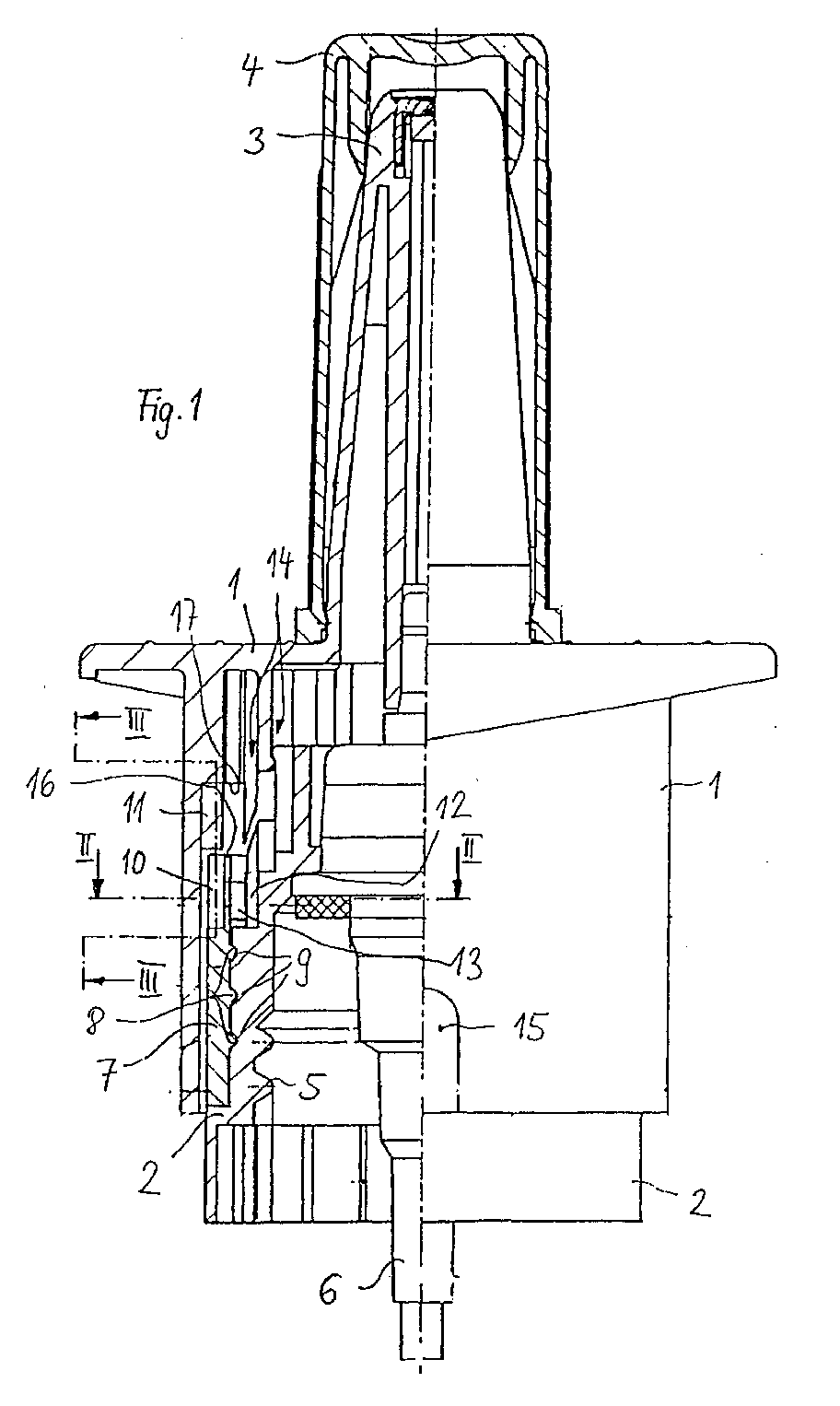
- the dosing device has a base body 2, which in the illustrated embodiment than can be screwed onto a container, in particular a bottle Screw cap is designed.
- the screw cap points to this an internal thread 5 on a corresponding bottle neck or a neck of a similar container can be screwed on.
- the base body 2 is positioned stationary.
- an actuating element 1 in the present case in Form of a nasal spray attachment, movable and secured against rotation stored on the base body 2.
- the stroke mobility of the actuating element 1 takes place coaxially to a central longitudinal axis of the base body 2, shown in dash-dot lines, but not with reference numerals is provided.
- the actuating element 1 has an upwardly projecting one Extension on which has an atomizing nozzle at its upper end 3 owns. The extension is closed by a cap 4.
- the actuating element 1 has a jacket in its lower region on, which surrounds the base body 2 over part of its height. In the area its top is the mantle with horizontal contact surfaces provided that pass into the nasal spray process. The contact surfaces serve as an area of attack for fingers of an operator's hand a corresponding pump movement on the actuating element 1 and thus on the entire metering device, in the present case a piston pump exercise.
- the actuator 1 is axially, i.e. parallel to the central longitudinal axis of the base body 2, running guide ribs and - grooves 14 guided movable and secured against rotation.
- the guide ribs and grooves via corresponding unspecified Ring shoulder sections in an upper end position of the actuating element 1 positively connected to one another in the axial direction, which creates an upper axial limit for the actuator 1 is achieved.
- the actuating element 1 by spring forces a known pump device in the unloaded state pressed against the stop thus formed.
- the actuating element 1 acts on the piston pump Pump device 6, the suction line in the storage container, not shown protrudes.
- a counting ring 7 is arranged, which is connected by means of an internal thread 8 a corresponding external thread 9 on the outer circumference of the Base body 2 is guided in a helically movable manner.
- the counting ring 7 has an external toothing in its upper edge area 10 (Figs. 2 and 3).
- Corresponding teeth of the axial toothing 10 protrude axially upwards and each have - in the circumferential direction an inclined tooth flank on the same side. corresponding for this purpose is on the inside of the jacket of the actuating element 1 a corresponding number of teeth of a further axial toothing 11 provided, which are integrally formed on the actuating element 1 is.
- the teeth of the axial toothing 11 are correspondingly opposite directed downward to the axial toothing 10. Every tooth has a correspondingly corresponding oblique tooth flank.
- the Axial gears 10 and 11 are arranged axially one above the other in such a way that with a stroke movement of the actuator 1 down the teeth of the upper axial toothing 11 with their oblique tooth flanks on the corresponding oblique tooth flanks of the lower one Axial teeth 10 hit and so on the counter ring 7 a force in Exercise circumferential direction.
- the counting ring 7 Due to the positive guidance of the counter ring 7 along the screw or spiral track, the counting ring 7 is thus on the one hand twisted in the circumferential direction by a certain amount and the other along the slope of the thread Guide means 8, 9 moved up or down.
- the spring bars 13 and the supporting toothing 12 form in connection with the axial toothing 10, 11 switching means for the counting ring, the counting ring move incrementally in the counting direction.
- a preferred embodiment sees an inner diameter of the counter ring 7 of 23mm Pitch for the guide thread of 2mm.
- the counter ring 7 In the upper edge area of the counter ring 7 is the inside of the cylindrical Sleeve section and thus at the level of the axial toothing 10 a defined number of spring bars 13 are provided, which according to FIG. 2 are aligned obliquely and with a corresponding support toothing 12 cooperate on the outer jacket of the base body 2. Ensure the spring bars 13 in connection with the supporting toothing 12 that the counter ring 7 only in a single direction of rotation is rotatable. The spring bars lock in the opposite direction of rotation 13 and the support toothing 12 a corresponding rotary movement the counting ring 7.
- the spring bars 13, the support teeth 12 and the axial gears 10, 11 are coordinated with one another in such a way that with a lifting movement of the actuating element 1, the counting ring 7 in each case is moved forward by a single counting step and no longer can be turned back to the original position.
- the spring bars 13 block rotary movements of the counter ring 7 against the defined Counting direction.
- the counting ring has one of the numbering on its outer circumference consecutive counting steps corresponding number sequence, the Number sequence in the present embodiment according to the Pitch of the guide thread, in particular running or counter-rotating, helically applied along the outer circumference of the counter ring 7 is.
- the jacket of the actuating element 1 has a viewing opening 15 which is designed in such a way that there is always a number, namely the the associated counting step is recognizable.
- the The sequence of numbers does not increase continuously, but in stages along the outer circumference the counting ring applied.
- Viewing opening provided a variable viewing window, which by means of positive guidance depending on the rotation of the counter ring is moved to capture the current number of the number sequence to be able to.
- At least two viewing openings at different heights and / or on different circumferential areas of the counting ring provided alternatively the corresponding numbers of the steadily or discontinuously increasing or make the descending sequence of numbers visible.
- An upper end face 16 of the counter ring 7 is used in connection with corresponding ones Support surfaces 17 of the actuating element 1 as locking means, the one after a certain number of counting steps Operation of the metering device blocked.
- the counting ring 7 moves - starting from the first stroke - with the number of strokes gradually in the manner of a snail on the base body 2 upwards, which is shown via the viewing opening 15, which Counting step is reached. After a specified number of counting steps the counting ring 7 has screwed up so far that the actuating element 1 no longer or almost no longer downwards can be pressed, since the support surface 17 and the end face 16 on each other to meet. Now the end of the dosing processes has been reached, with the Number of counter rings and thus the number of strokes in each case exactly to the desired dosage and application time for the medium to be applied are coordinated.
Abstract
Description
- Fig. 1
- zeigt in teilweise geschnittener Darstellung eine Ausführungsform einer erfindungsgemäßen Dosiervorrichtung,
- Fig. 2
- schematisch einen Ausschnitt der Dosiervorrichtung nach Fig. 1 entlang der Schnittlinie II-II in Fig. 1 und
- Fig. 3
- ebenfalls schematisch eine Schnittdarstellung eines Ausschnittes III-III in Fig. 1.
Claims (4)
- Dosiervorrichtung mit einem Grundkörper sowie mit einem an dem Grundkörper verdrehgesichert und hubbeweglich gelagerten Betätigungselement, sowie mit einer Zähleinrichtung für die Betätigungshübe, die einen abhängig von einer Hubbewegung des Betätigungselementes zwangsgekoppelt drehbaren Zählring aufweist, und mit wenigstens einem Sperrmittel zum Blockieren des Betätigungselementes nach einer vorgegebenen Anzahl von Betätigungshüben, dadurch gekennzeichnet, dass das wenigstens eine Sperrmittel (16, 17) dem Zählring (7) derart zugeordnet ist, dass der Zählring (7) mehr als eine volle Umdrehung durchführen kann, bevor das Betätigungselement (1) blockiert wird.
- Dosiervorrichtung nach Anspruch 1, dadurch gekennzeichnet, dass dem Zählring (7) Führungsmittel (8, 9) zugeordnet sind, die den Zählring (7) in Hubrichtung überlagert oder alternativ zu einer Drehbewegung führen.
- Dosiervorrichtung nach Anspruch 2, dadurch gekennzeichnet, dass der Zählring (7) wendelförmig drehbar relativ zu einer Mittellängsachse des Grundkörpers (2) beweglich gelagert ist.
- Dosiervorrichtung nach Anspruch 3, dadurch gekennzeichnet, dass der Zählring (7) mittels eines Schraubgewindes (8, 9) an dem Grundkörper (2) oder an dem Betätigungselement (1) gehalten ist, dessen Steigung auf Weiterschaltungsmittel (12, 13) für den Zählring (7) abgestimmt ist.
Applications Claiming Priority (2)
| Application Number | Priority Date | Filing Date | Title |
|---|---|---|---|
| DE10159692A DE10159692A1 (de) | 2001-11-29 | 2001-11-29 | Dosiervorrichtung |
| DE10159692 | 2001-11-29 |
Publications (3)
| Publication Number | Publication Date |
|---|---|
| EP1316365A2 true EP1316365A2 (de) | 2003-06-04 |
| EP1316365A3 EP1316365A3 (de) | 2005-08-10 |
| EP1316365B1 EP1316365B1 (de) | 2006-12-27 |
Family
ID=7708105
Family Applications (1)
| Application Number | Title | Priority Date | Filing Date |
|---|---|---|---|
| EP02023171A Expired - Lifetime EP1316365B1 (de) | 2001-11-29 | 2002-10-16 | Dosiervorrichtung |
Country Status (5)
| Country | Link |
|---|---|
| US (1) | US7306116B2 (de) |
| EP (1) | EP1316365B1 (de) |
| AT (1) | ATE349281T1 (de) |
| DE (2) | DE10159692A1 (de) |
| ES (1) | ES2276881T3 (de) |
Cited By (2)
| Publication number | Priority date | Publication date | Assignee | Title |
|---|---|---|---|---|
| WO2007022898A3 (en) * | 2005-08-24 | 2007-05-31 | Boehringer Ingelheim Int | Atomiser comprising a counter and an end of operation lock |
| WO2009086009A1 (en) * | 2007-12-21 | 2009-07-09 | Schering Corporation | Dose counters and containers |
Families Citing this family (20)
| Publication number | Priority date | Publication date | Assignee | Title |
|---|---|---|---|---|
| ATE453421T1 (de) * | 2002-05-09 | 2010-01-15 | Glaxo Group Ltd | Flüssigkeit abgebende vorrichtung |
| GB0405477D0 (en) * | 2004-03-11 | 2004-04-21 | Glaxo Group Ltd | A fluid dispensing device |
| PT1699512E (pt) | 2003-11-03 | 2012-09-11 | Glaxo Group Ltd | Dispositivo distribuidor de fluido |
| GB0327112D0 (en) | 2003-11-21 | 2003-12-24 | Clincial Designs Ltd | Dispenser and reservoir |
| PL1725285T3 (pl) * | 2004-03-10 | 2020-03-31 | Glaxo Group Limited | Urządzenie dozujące z członem ograniczającym |
| DE102005009294A1 (de) * | 2004-07-13 | 2006-02-16 | Ing. Erich Pfeiffer Gmbh | Spender für Medien |
| GB0425518D0 (en) | 2004-11-19 | 2004-12-22 | Clinical Designs Ltd | Substance source |
| GB0428204D0 (en) | 2004-12-23 | 2005-01-26 | Clinical Designs Ltd | Medicament container |
| GB0507224D0 (en) * | 2005-04-09 | 2005-05-18 | Glaxo Group Ltd | A fluid dispensing device |
| GB0518355D0 (en) * | 2005-09-08 | 2005-10-19 | Glaxo Group Ltd | An inhaler |
| GB0518400D0 (en) | 2005-09-09 | 2005-10-19 | Clinical Designs Ltd | Dispenser |
| GB0623732D0 (en) * | 2006-11-28 | 2007-01-10 | Optinose As | Powder delivery devices |
| GB0904059D0 (en) | 2009-03-10 | 2009-04-22 | Euro Celtique Sa | Counter |
| GB0904040D0 (en) | 2009-03-10 | 2009-04-22 | Euro Celtique Sa | Counter |
| GB0920499D0 (en) | 2009-11-23 | 2010-01-06 | 3M Innovative Properties Co | Dose counter |
| DE102013220492A1 (de) * | 2013-10-10 | 2015-04-16 | Aptar Radolfzell Gmbh | Kindergesicherte Austragvorrichtung |
| MX2016014403A (es) | 2014-05-07 | 2017-01-20 | Boehringer Ingelheim Int | Recipiente, dispositivo indicador y nebulizador. |
| WO2015169430A1 (en) * | 2014-05-07 | 2015-11-12 | Boehringer Ingelheim International Gmbh | Nebulizer |
| NZ731349A (en) | 2014-09-29 | 2022-07-01 | Journey Medical Corp | Device and method for dispensing a drug |
| CN117550227A (zh) * | 2022-03-08 | 2024-02-13 | 艾特申博(苏州)医药科技有限公司 | 用于雾化器的触发组件以及雾化器 |
Citations (1)
| Publication number | Priority date | Publication date | Assignee | Title |
|---|---|---|---|---|
| DE3302160A1 (de) | 1983-01-22 | 1984-07-26 | Ing. Erich Pfeiffer GmbH & Co KG, 7760 Radolfzell | Betaetigbare dosiereinrichtung |
Family Cites Families (13)
| Publication number | Priority date | Publication date | Assignee | Title |
|---|---|---|---|---|
| US4162746A (en) * | 1977-06-22 | 1979-07-31 | Diamond International Corporation | Liquid dispenser locking means |
| US4220247A (en) * | 1979-04-04 | 1980-09-02 | Kramer Steven G | Closure members |
| DE3225910A1 (de) * | 1982-07-10 | 1984-01-12 | Pfeiffer Zerstäuber Vertriebsgesellschaft mbH & Co KG, 7760 Radolfzell | Zerstaeuber- oder dosierpumpe |
| US4871092A (en) * | 1982-07-10 | 1989-10-03 | Ing. Erich Pfeiffer Gmbh & Co. Kg | Atomizing or metering pump |
| DE3544985A1 (de) * | 1985-12-19 | 1987-06-25 | Pfeiffer Erich Gmbh & Co Kg | Austragvorrichtung fuer fliessfaehige medien |
| US4773567A (en) * | 1986-04-21 | 1988-09-27 | Stoody William R | Child resistant latching actuator for aerosol/pump valve |
| DE4021263C2 (de) * | 1990-07-04 | 1996-04-11 | Pfeiffer Erich Gmbh & Co Kg | Austragvorrichtung für Medien |
| DE4027672A1 (de) * | 1990-08-31 | 1992-03-05 | Pfeiffer Erich Gmbh & Co Kg | Austragvorrichtung fuer medien |
| DE4030530A1 (de) * | 1990-09-27 | 1992-04-02 | Pfeiffer Erich Gmbh & Co Kg | Austragvorrichtung fuer medien |
| DE19739989A1 (de) * | 1997-09-11 | 1999-03-18 | Pfeiffer Erich Gmbh & Co Kg | Spender für Medien |
| DE29814647U1 (de) * | 1998-08-14 | 1999-12-23 | Wischerath Josef Gmbh Co Kg | Inhalator mit einer Dosierzähleinrichtung |
| GB2348928B (en) * | 1999-04-07 | 2001-10-31 | Bespak Plc | Improvements in or relating to dispensing apparatus |
| IT1312426B1 (it) * | 1999-06-30 | 2002-04-17 | Microspray Delta Spa | Distributore di dosi di un liquido,con dispositivo per il conteggio di un elevato numero di dosi erogate |
-
2001
- 2001-11-29 DE DE10159692A patent/DE10159692A1/de not_active Withdrawn
-
2002
- 2002-10-16 DE DE50209067T patent/DE50209067D1/de not_active Expired - Lifetime
- 2002-10-16 EP EP02023171A patent/EP1316365B1/de not_active Expired - Lifetime
- 2002-10-16 ES ES02023171T patent/ES2276881T3/es not_active Expired - Lifetime
- 2002-10-16 AT AT02023171T patent/ATE349281T1/de not_active IP Right Cessation
- 2002-11-25 US US10/303,482 patent/US7306116B2/en not_active Expired - Fee Related
Patent Citations (1)
| Publication number | Priority date | Publication date | Assignee | Title |
|---|---|---|---|---|
| DE3302160A1 (de) | 1983-01-22 | 1984-07-26 | Ing. Erich Pfeiffer GmbH & Co KG, 7760 Radolfzell | Betaetigbare dosiereinrichtung |
Cited By (7)
| Publication number | Priority date | Publication date | Assignee | Title |
|---|---|---|---|---|
| WO2007022898A3 (en) * | 2005-08-24 | 2007-05-31 | Boehringer Ingelheim Int | Atomiser comprising a counter and an end of operation lock |
| EA012320B1 (ru) * | 2005-08-24 | 2009-08-28 | Бёрингер Ингельхайм Интернациональ Гмбх | Распылитель, включающий счетное устройство и замок, блокирующий его операции |
| EP2436453A1 (de) * | 2005-08-24 | 2012-04-04 | Boehringer Ingelheim International Gmbh | Zerstäuber mit einem Zähler und einer Betriebsendsperre |
| CN101247897B (zh) * | 2005-08-24 | 2013-06-12 | 贝林格尔·英格海姆国际有限公司 | 雾化器 |
| CN103272730A (zh) * | 2005-08-24 | 2013-09-04 | 贝林格尔.英格海姆国际有限公司 | 雾化器 |
| CN103272730B (zh) * | 2005-08-24 | 2016-12-07 | 贝林格尔.英格海姆国际有限公司 | 雾化器 |
| WO2009086009A1 (en) * | 2007-12-21 | 2009-07-09 | Schering Corporation | Dose counters and containers |
Also Published As
| Publication number | Publication date |
|---|---|
| DE10159692A1 (de) | 2003-06-12 |
| US20030100867A1 (en) | 2003-05-29 |
| EP1316365B1 (de) | 2006-12-27 |
| US7306116B2 (en) | 2007-12-11 |
| EP1316365A3 (de) | 2005-08-10 |
| ATE349281T1 (de) | 2007-01-15 |
| DE50209067D1 (de) | 2007-02-08 |
| ES2276881T3 (es) | 2007-07-01 |
Similar Documents
| Publication | Publication Date | Title |
|---|---|---|
| EP1316365B1 (de) | Dosiervorrichtung | |
| EP0831947B1 (de) | Injektionsgerät | |
| EP0472985B1 (de) | Austragvorrichtung für Medien | |
| DE4021263C2 (de) | Austragvorrichtung für Medien | |
| EP0472915B1 (de) | Austragvorrichtung für Medien | |
| DE60020189T2 (de) | Spender zur Abgabe abgemessener Mengen einer Flüssigkeit, versehen mit einer Vorrichtung zum Zählen einer großen Zahl abgegebener Dosen | |
| EP1383405B1 (de) | Spendervorrichtung für eine cremeförmige oder durch bestreichen einer oberfläche sich abtragenden masse | |
| DE3302160A1 (de) | Betaetigbare dosiereinrichtung | |
| DE19509532A1 (de) | Brausekopf | |
| EP1173078B1 (de) | Creme- und deospender | |
| EP1084763A2 (de) | Spender zum ggf. zerstäubten Ausbringen eines insbesondere flüssigen Mediums aus einem Behältnis | |
| EP0828527A1 (de) | Injektionsgerät | |
| EP2318079B1 (de) | Antriebseinheit für dosiszähler | |
| DE69724400T2 (de) | Vorrichtung mit kontrolliertem Abgabemuster | |
| DE102005018306B4 (de) | Antiebs- und/oder Dosiermodul mit einem Drehanschlag | |
| EP1140669A1 (de) | Dosiervorrichtung für schüttgüter | |
| DE102019102718A1 (de) | Spender zur Ausgabe von fließfähigen, beispielsweise flüssigen bis pastösen Massen | |
| WO1998001171A1 (de) | Injektionsgerät zum injizieren von flüssigkeit | |
| DE10327868A1 (de) | Stellantrieb zur reversiblen Bewegung einer Ventilklappe eines Ventils | |
| EP0392314A2 (de) | Drehverschluss zum Verschliessen der axialen Öffnung eines hohlzylindrischen Körpers | |
| DE3825269C2 (de) | ||
| EP0993800B1 (de) | Kaffeemaschine | |
| EP1002195B1 (de) | Regelvorrichtung sowie verfahren zu deren herstellung | |
| EP0886127B1 (de) | Vorrichtung zum Dosieren von viskosen Massen | |
| DE4321968A1 (de) | Klebstift |
Legal Events
| Date | Code | Title | Description |
|---|---|---|---|
| PUAI | Public reference made under article 153(3) epc to a published international application that has entered the european phase |
Free format text: ORIGINAL CODE: 0009012 |
|
| AK | Designated contracting states |
Designated state(s): AT BE BG CH CY CZ DE DK EE ES FI FR GB GR IE IT LI LU MC NL PT SE SK TR |
|
| AX | Request for extension of the european patent |
Extension state: AL LT LV MK RO SI |
|
| PUAL | Search report despatched |
Free format text: ORIGINAL CODE: 0009013 |
|
| AK | Designated contracting states |
Kind code of ref document: A3 Designated state(s): AT BE BG CH CY CZ DE DK EE ES FI FR GB GR IE IT LI LU MC NL PT SE SK TR |
|
| AX | Request for extension of the european patent |
Extension state: AL LT LV MK RO SI |
|
| RIC1 | Information provided on ipc code assigned before grant |
Ipc: 7G 01F 11/02 B Ipc: 7A 61M 15/00 B Ipc: 7B 05B 11/00 A |
|
| 17P | Request for examination filed |
Effective date: 20051019 |
|
| AKX | Designation fees paid |
Designated state(s): AT BE BG CH CY CZ DE DK EE ES FI FR GB GR IE IT LI LU MC NL PT SE SK TR |
|
| GRAP | Despatch of communication of intention to grant a patent |
Free format text: ORIGINAL CODE: EPIDOSNIGR1 |
|
| GRAS | Grant fee paid |
Free format text: ORIGINAL CODE: EPIDOSNIGR3 |
|
| GRAA | (expected) grant |
Free format text: ORIGINAL CODE: 0009210 |
|
| AK | Designated contracting states |
Kind code of ref document: B1 Designated state(s): AT BE BG CH CY CZ DE DK EE ES FI FR GB GR IE IT LI LU MC NL PT SE SK TR |
|
| PG25 | Lapsed in a contracting state [announced via postgrant information from national office to epo] |
Ref country code: SK Free format text: LAPSE BECAUSE OF FAILURE TO SUBMIT A TRANSLATION OF THE DESCRIPTION OR TO PAY THE FEE WITHIN THE PRESCRIBED TIME-LIMIT Effective date: 20061227 Ref country code: FI Free format text: LAPSE BECAUSE OF FAILURE TO SUBMIT A TRANSLATION OF THE DESCRIPTION OR TO PAY THE FEE WITHIN THE PRESCRIBED TIME-LIMIT Effective date: 20061227 Ref country code: CZ Free format text: LAPSE BECAUSE OF FAILURE TO SUBMIT A TRANSLATION OF THE DESCRIPTION OR TO PAY THE FEE WITHIN THE PRESCRIBED TIME-LIMIT Effective date: 20061227 Ref country code: NL Free format text: LAPSE BECAUSE OF FAILURE TO SUBMIT A TRANSLATION OF THE DESCRIPTION OR TO PAY THE FEE WITHIN THE PRESCRIBED TIME-LIMIT Effective date: 20061227 Ref country code: DK Free format text: LAPSE BECAUSE OF FAILURE TO SUBMIT A TRANSLATION OF THE DESCRIPTION OR TO PAY THE FEE WITHIN THE PRESCRIBED TIME-LIMIT Effective date: 20061227 Ref country code: IE Free format text: LAPSE BECAUSE OF FAILURE TO SUBMIT A TRANSLATION OF THE DESCRIPTION OR TO PAY THE FEE WITHIN THE PRESCRIBED TIME-LIMIT Effective date: 20061227 |
|
| REG | Reference to a national code |
Ref country code: GB Ref legal event code: FG4D Free format text: NOT ENGLISH |
|
| REG | Reference to a national code |
Ref country code: IE Ref legal event code: FG4D Free format text: LANGUAGE OF EP DOCUMENT: GERMAN |
|
| REF | Corresponds to: |
Ref document number: 50209067 Country of ref document: DE Date of ref document: 20070208 Kind code of ref document: P |
|
| REG | Reference to a national code |
Ref country code: CH Ref legal event code: NV Representative=s name: ZIMMERLI, WAGNER & PARTNER AG |
|
| GBT | Gb: translation of ep patent filed (gb section 77(6)(a)/1977) |
Effective date: 20070215 |
|
| PG25 | Lapsed in a contracting state [announced via postgrant information from national office to epo] |
Ref country code: SE Free format text: LAPSE BECAUSE OF FAILURE TO SUBMIT A TRANSLATION OF THE DESCRIPTION OR TO PAY THE FEE WITHIN THE PRESCRIBED TIME-LIMIT Effective date: 20070327 Ref country code: BG Free format text: LAPSE BECAUSE OF FAILURE TO SUBMIT A TRANSLATION OF THE DESCRIPTION OR TO PAY THE FEE WITHIN THE PRESCRIBED TIME-LIMIT Effective date: 20070327 |
|
| PG25 | Lapsed in a contracting state [announced via postgrant information from national office to epo] |
Ref country code: PT Free format text: LAPSE BECAUSE OF FAILURE TO SUBMIT A TRANSLATION OF THE DESCRIPTION OR TO PAY THE FEE WITHIN THE PRESCRIBED TIME-LIMIT Effective date: 20070528 |
|
| NLV1 | Nl: lapsed or annulled due to failure to fulfill the requirements of art. 29p and 29m of the patents act | ||
| ET | Fr: translation filed | ||
| REG | Reference to a national code |
Ref country code: ES Ref legal event code: FG2A Ref document number: 2276881 Country of ref document: ES Kind code of ref document: T3 |
|
| PLBE | No opposition filed within time limit |
Free format text: ORIGINAL CODE: 0009261 |
|
| STAA | Information on the status of an ep patent application or granted ep patent |
Free format text: STATUS: NO OPPOSITION FILED WITHIN TIME LIMIT |
|
| 26N | No opposition filed |
Effective date: 20070928 |
|
| BERE | Be: lapsed |
Owner name: ING. ERICH PFEIFFER G.M.B.H. Effective date: 20071031 |
|
| PG25 | Lapsed in a contracting state [announced via postgrant information from national office to epo] |
Ref country code: GR Free format text: LAPSE BECAUSE OF FAILURE TO SUBMIT A TRANSLATION OF THE DESCRIPTION OR TO PAY THE FEE WITHIN THE PRESCRIBED TIME-LIMIT Effective date: 20070328 |
|
| PG25 | Lapsed in a contracting state [announced via postgrant information from national office to epo] |
Ref country code: MC Free format text: LAPSE BECAUSE OF NON-PAYMENT OF DUE FEES Effective date: 20071031 |
|
| PG25 | Lapsed in a contracting state [announced via postgrant information from national office to epo] |
Ref country code: BE Free format text: LAPSE BECAUSE OF NON-PAYMENT OF DUE FEES Effective date: 20071031 |
|
| PG25 | Lapsed in a contracting state [announced via postgrant information from national office to epo] |
Ref country code: EE Free format text: LAPSE BECAUSE OF FAILURE TO SUBMIT A TRANSLATION OF THE DESCRIPTION OR TO PAY THE FEE WITHIN THE PRESCRIBED TIME-LIMIT Effective date: 20061227 |
|
| PG25 | Lapsed in a contracting state [announced via postgrant information from national office to epo] |
Ref country code: AT Free format text: LAPSE BECAUSE OF NON-PAYMENT OF DUE FEES Effective date: 20071016 |
|
| PG25 | Lapsed in a contracting state [announced via postgrant information from national office to epo] |
Ref country code: CY Free format text: LAPSE BECAUSE OF FAILURE TO SUBMIT A TRANSLATION OF THE DESCRIPTION OR TO PAY THE FEE WITHIN THE PRESCRIBED TIME-LIMIT Effective date: 20061227 Ref country code: LU Free format text: LAPSE BECAUSE OF NON-PAYMENT OF DUE FEES Effective date: 20071016 |
|
| PG25 | Lapsed in a contracting state [announced via postgrant information from national office to epo] |
Ref country code: TR Free format text: LAPSE BECAUSE OF FAILURE TO SUBMIT A TRANSLATION OF THE DESCRIPTION OR TO PAY THE FEE WITHIN THE PRESCRIBED TIME-LIMIT Effective date: 20061227 |
|
| REG | Reference to a national code |
Ref country code: CH Ref legal event code: PFA Owner name: ING. ERICH PFEIFFER GMBH Free format text: ING. ERICH PFEIFFER GMBH#OESCHLESTRASSE 124-126#78315 RADOLFZELL (DE) -TRANSFER TO- ING. ERICH PFEIFFER GMBH#OESCHLESTRASSE 124-126#78315 RADOLFZELL (DE) |
|
| REG | Reference to a national code |
Ref country code: DE Ref legal event code: R082 Ref document number: 50209067 Country of ref document: DE Representative=s name: PATENTANWAELTE RUFF, WILHELM, BEIER, DAUSTER &, DE Effective date: 20121025 Ref country code: DE Ref legal event code: R081 Ref document number: 50209067 Country of ref document: DE Owner name: APTAR RADOLFZELL GMBH, DE Free format text: FORMER OWNER: ING. ERICH PFEFFER GMBH, 78315 RADOLFZELL, DE Effective date: 20121025 Ref country code: DE Ref legal event code: R082 Ref document number: 50209067 Country of ref document: DE Representative=s name: PATENTANWALTSKANZLEI CARTAGENA PARTNERSCHAFTSG, DE Effective date: 20121025 |
|
| PGFP | Annual fee paid to national office [announced via postgrant information from national office to epo] |
Ref country code: IT Payment date: 20131025 Year of fee payment: 12 Ref country code: ES Payment date: 20131022 Year of fee payment: 12 |
|
| REG | Reference to a national code |
Ref country code: CH Ref legal event code: NV Representative=s name: WAGNER PATENT AG, CH |
|
| PG25 | Lapsed in a contracting state [announced via postgrant information from national office to epo] |
Ref country code: IT Free format text: LAPSE BECAUSE OF NON-PAYMENT OF DUE FEES Effective date: 20141016 |
|
| REG | Reference to a national code |
Ref country code: FR Ref legal event code: PLFP Year of fee payment: 14 |
|
| REG | Reference to a national code |
Ref country code: ES Ref legal event code: FD2A Effective date: 20151126 |
|
| PGFP | Annual fee paid to national office [announced via postgrant information from national office to epo] |
Ref country code: CH Payment date: 20151026 Year of fee payment: 14 Ref country code: GB Payment date: 20151026 Year of fee payment: 14 |
|
| REG | Reference to a national code |
Ref country code: DE Ref legal event code: R082 Ref document number: 50209067 Country of ref document: DE Representative=s name: PATENTANWALTSKANZLEI CARTAGENA PARTNERSCHAFTSG, DE |
|
| PG25 | Lapsed in a contracting state [announced via postgrant information from national office to epo] |
Ref country code: ES Free format text: LAPSE BECAUSE OF NON-PAYMENT OF DUE FEES Effective date: 20141017 |
|
| REG | Reference to a national code |
Ref country code: FR Ref legal event code: PLFP Year of fee payment: 15 |
|
| PGFP | Annual fee paid to national office [announced via postgrant information from national office to epo] |
Ref country code: FR Payment date: 20161025 Year of fee payment: 15 Ref country code: DE Payment date: 20161019 Year of fee payment: 15 |
|
| REG | Reference to a national code |
Ref country code: CH Ref legal event code: PL |
|
| GBPC | Gb: european patent ceased through non-payment of renewal fee |
Effective date: 20161016 |
|
| PG25 | Lapsed in a contracting state [announced via postgrant information from national office to epo] |
Ref country code: LI Free format text: LAPSE BECAUSE OF NON-PAYMENT OF DUE FEES Effective date: 20161031 Ref country code: CH Free format text: LAPSE BECAUSE OF NON-PAYMENT OF DUE FEES Effective date: 20161031 Ref country code: GB Free format text: LAPSE BECAUSE OF NON-PAYMENT OF DUE FEES Effective date: 20161016 |
|
| REG | Reference to a national code |
Ref country code: DE Ref legal event code: R119 Ref document number: 50209067 Country of ref document: DE |
|
| REG | Reference to a national code |
Ref country code: FR Ref legal event code: ST Effective date: 20180629 |
|
| PG25 | Lapsed in a contracting state [announced via postgrant information from national office to epo] |
Ref country code: DE Free format text: LAPSE BECAUSE OF NON-PAYMENT OF DUE FEES Effective date: 20180501 |
|
| PG25 | Lapsed in a contracting state [announced via postgrant information from national office to epo] |
Ref country code: FR Free format text: LAPSE BECAUSE OF NON-PAYMENT OF DUE FEES Effective date: 20171031 |