EP1314972A1 - Spectrophotometer and its use - Google Patents
Spectrophotometer and its use Download PDFInfo
- Publication number
- EP1314972A1 EP1314972A1 EP01127427A EP01127427A EP1314972A1 EP 1314972 A1 EP1314972 A1 EP 1314972A1 EP 01127427 A EP01127427 A EP 01127427A EP 01127427 A EP01127427 A EP 01127427A EP 1314972 A1 EP1314972 A1 EP 1314972A1
- Authority
- EP
- European Patent Office
- Prior art keywords
- light
- measuring
- lighting
- measurement
- sample
- Prior art date
- Legal status (The legal status is an assumption and is not a legal conclusion. Google has not performed a legal analysis and makes no representation as to the accuracy of the status listed.)
- Granted
Links
- 238000005259 measurement Methods 0.000 claims abstract description 76
- 230000003595 spectral effect Effects 0.000 claims abstract description 37
- 238000005286 illumination Methods 0.000 claims abstract description 18
- 230000003287 optical effect Effects 0.000 claims description 26
- 238000003384 imaging method Methods 0.000 claims description 14
- 238000001228 spectrum Methods 0.000 claims description 14
- 238000007639 printing Methods 0.000 claims description 9
- 238000012937 correction Methods 0.000 claims description 6
- 238000001514 detection method Methods 0.000 claims description 5
- 230000006870 function Effects 0.000 claims description 5
- 238000000295 emission spectrum Methods 0.000 claims description 3
- 238000012545 processing Methods 0.000 claims description 3
- 238000000034 method Methods 0.000 description 17
- 230000008569 process Effects 0.000 description 11
- 230000000694 effects Effects 0.000 description 10
- 238000004519 manufacturing process Methods 0.000 description 9
- 230000001419 dependent effect Effects 0.000 description 8
- 238000005516 engineering process Methods 0.000 description 8
- 230000008859 change Effects 0.000 description 7
- 239000003086 colorant Substances 0.000 description 6
- 238000013461 design Methods 0.000 description 6
- 239000013307 optical fiber Substances 0.000 description 6
- 238000011161 development Methods 0.000 description 5
- 230000018109 developmental process Effects 0.000 description 5
- 238000011156 evaluation Methods 0.000 description 5
- 239000000463 material Substances 0.000 description 5
- 238000012800 visualization Methods 0.000 description 5
- 230000008901 benefit Effects 0.000 description 4
- 238000010276 construction Methods 0.000 description 4
- 238000009434 installation Methods 0.000 description 4
- 239000000049 pigment Substances 0.000 description 4
- 230000005284 excitation Effects 0.000 description 3
- 238000012360 testing method Methods 0.000 description 3
- 238000003491 array Methods 0.000 description 2
- 239000004327 boric acid Substances 0.000 description 2
- 238000006243 chemical reaction Methods 0.000 description 2
- 230000004456 color vision Effects 0.000 description 2
- 238000004891 communication Methods 0.000 description 2
- 230000008878 coupling Effects 0.000 description 2
- 238000010168 coupling process Methods 0.000 description 2
- 238000005859 coupling reaction Methods 0.000 description 2
- 238000010586 diagram Methods 0.000 description 2
- 238000004020 luminiscence type Methods 0.000 description 2
- 230000005693 optoelectronics Effects 0.000 description 2
- 238000004806 packaging method and process Methods 0.000 description 2
- 238000000985 reflectance spectrum Methods 0.000 description 2
- 238000009877 rendering Methods 0.000 description 2
- 239000000758 substrate Substances 0.000 description 2
- 238000012549 training Methods 0.000 description 2
- 230000000007 visual effect Effects 0.000 description 2
- 241001466538 Gymnogyps Species 0.000 description 1
- 239000004904 UV filter Substances 0.000 description 1
- 230000000712 assembly Effects 0.000 description 1
- 238000000429 assembly Methods 0.000 description 1
- 230000033228 biological regulation Effects 0.000 description 1
- 238000004364 calculation method Methods 0.000 description 1
- 239000000969 carrier Substances 0.000 description 1
- 239000013065 commercial product Substances 0.000 description 1
- 238000000354 decomposition reaction Methods 0.000 description 1
- 238000001739 density measurement Methods 0.000 description 1
- 230000008030 elimination Effects 0.000 description 1
- 238000003379 elimination reaction Methods 0.000 description 1
- 238000001914 filtration Methods 0.000 description 1
- 239000011888 foil Substances 0.000 description 1
- 238000002347 injection Methods 0.000 description 1
- 239000007924 injection Substances 0.000 description 1
- 230000010354 integration Effects 0.000 description 1
- 238000012634 optical imaging Methods 0.000 description 1
- 230000010287 polarization Effects 0.000 description 1
- 230000005855 radiation Effects 0.000 description 1
- 230000001850 reproductive effect Effects 0.000 description 1
- 229920006395 saturated elastomer Polymers 0.000 description 1
- 239000004065 semiconductor Substances 0.000 description 1
- 238000012883 sequential measurement Methods 0.000 description 1
- 238000004088 simulation Methods 0.000 description 1
- 239000000243 solution Substances 0.000 description 1
- 125000006850 spacer group Chemical group 0.000 description 1
- 238000010998 test method Methods 0.000 description 1
Images


Classifications
-
- G—PHYSICS
- G01—MEASURING; TESTING
- G01J—MEASUREMENT OF INTENSITY, VELOCITY, SPECTRAL CONTENT, POLARISATION, PHASE OR PULSE CHARACTERISTICS OF INFRARED, VISIBLE OR ULTRAVIOLET LIGHT; COLORIMETRY; RADIATION PYROMETRY
- G01J3/00—Spectrometry; Spectrophotometry; Monochromators; Measuring colours
- G01J3/46—Measurement of colour; Colour measuring devices, e.g. colorimeters
- G01J3/50—Measurement of colour; Colour measuring devices, e.g. colorimeters using electric radiation detectors
-
- G—PHYSICS
- G01—MEASURING; TESTING
- G01J—MEASUREMENT OF INTENSITY, VELOCITY, SPECTRAL CONTENT, POLARISATION, PHASE OR PULSE CHARACTERISTICS OF INFRARED, VISIBLE OR ULTRAVIOLET LIGHT; COLORIMETRY; RADIATION PYROMETRY
- G01J3/00—Spectrometry; Spectrophotometry; Monochromators; Measuring colours
- G01J3/02—Details
- G01J3/0205—Optical elements not provided otherwise, e.g. optical manifolds, diffusers, windows
- G01J3/0208—Optical elements not provided otherwise, e.g. optical manifolds, diffusers, windows using focussing or collimating elements, e.g. lenses or mirrors; performing aberration correction
-
- G—PHYSICS
- G01—MEASURING; TESTING
- G01J—MEASUREMENT OF INTENSITY, VELOCITY, SPECTRAL CONTENT, POLARISATION, PHASE OR PULSE CHARACTERISTICS OF INFRARED, VISIBLE OR ULTRAVIOLET LIGHT; COLORIMETRY; RADIATION PYROMETRY
- G01J3/00—Spectrometry; Spectrophotometry; Monochromators; Measuring colours
- G01J3/02—Details
- G01J3/0205—Optical elements not provided otherwise, e.g. optical manifolds, diffusers, windows
- G01J3/021—Optical elements not provided otherwise, e.g. optical manifolds, diffusers, windows using plane or convex mirrors, parallel phase plates, or particular reflectors
-
- G—PHYSICS
- G01—MEASURING; TESTING
- G01J—MEASUREMENT OF INTENSITY, VELOCITY, SPECTRAL CONTENT, POLARISATION, PHASE OR PULSE CHARACTERISTICS OF INFRARED, VISIBLE OR ULTRAVIOLET LIGHT; COLORIMETRY; RADIATION PYROMETRY
- G01J3/00—Spectrometry; Spectrophotometry; Monochromators; Measuring colours
- G01J3/02—Details
- G01J3/0205—Optical elements not provided otherwise, e.g. optical manifolds, diffusers, windows
- G01J3/024—Optical elements not provided otherwise, e.g. optical manifolds, diffusers, windows using means for illuminating a slit efficiently (e.g. entrance slit of a spectrometer or entrance face of fiber)
-
- G—PHYSICS
- G01—MEASURING; TESTING
- G01J—MEASUREMENT OF INTENSITY, VELOCITY, SPECTRAL CONTENT, POLARISATION, PHASE OR PULSE CHARACTERISTICS OF INFRARED, VISIBLE OR ULTRAVIOLET LIGHT; COLORIMETRY; RADIATION PYROMETRY
- G01J3/00—Spectrometry; Spectrophotometry; Monochromators; Measuring colours
- G01J3/02—Details
- G01J3/0256—Compact construction
-
- G—PHYSICS
- G01—MEASURING; TESTING
- G01J—MEASUREMENT OF INTENSITY, VELOCITY, SPECTRAL CONTENT, POLARISATION, PHASE OR PULSE CHARACTERISTICS OF INFRARED, VISIBLE OR ULTRAVIOLET LIGHT; COLORIMETRY; RADIATION PYROMETRY
- G01J3/00—Spectrometry; Spectrophotometry; Monochromators; Measuring colours
- G01J3/02—Details
- G01J3/0272—Handheld
-
- G—PHYSICS
- G01—MEASURING; TESTING
- G01J—MEASUREMENT OF INTENSITY, VELOCITY, SPECTRAL CONTENT, POLARISATION, PHASE OR PULSE CHARACTERISTICS OF INFRARED, VISIBLE OR ULTRAVIOLET LIGHT; COLORIMETRY; RADIATION PYROMETRY
- G01J3/00—Spectrometry; Spectrophotometry; Monochromators; Measuring colours
- G01J3/02—Details
- G01J3/0278—Control or determination of height or angle information for sensors or receivers
-
- G—PHYSICS
- G01—MEASURING; TESTING
- G01J—MEASUREMENT OF INTENSITY, VELOCITY, SPECTRAL CONTENT, POLARISATION, PHASE OR PULSE CHARACTERISTICS OF INFRARED, VISIBLE OR ULTRAVIOLET LIGHT; COLORIMETRY; RADIATION PYROMETRY
- G01J3/00—Spectrometry; Spectrophotometry; Monochromators; Measuring colours
- G01J3/02—Details
- G01J3/0291—Housings; Spectrometer accessories; Spatial arrangement of elements, e.g. folded path arrangements
-
- G—PHYSICS
- G01—MEASURING; TESTING
- G01J—MEASUREMENT OF INTENSITY, VELOCITY, SPECTRAL CONTENT, POLARISATION, PHASE OR PULSE CHARACTERISTICS OF INFRARED, VISIBLE OR ULTRAVIOLET LIGHT; COLORIMETRY; RADIATION PYROMETRY
- G01J3/00—Spectrometry; Spectrophotometry; Monochromators; Measuring colours
- G01J3/02—Details
- G01J3/10—Arrangements of light sources specially adapted for spectrometry or colorimetry
-
- G—PHYSICS
- G01—MEASURING; TESTING
- G01J—MEASUREMENT OF INTENSITY, VELOCITY, SPECTRAL CONTENT, POLARISATION, PHASE OR PULSE CHARACTERISTICS OF INFRARED, VISIBLE OR ULTRAVIOLET LIGHT; COLORIMETRY; RADIATION PYROMETRY
- G01J3/00—Spectrometry; Spectrophotometry; Monochromators; Measuring colours
- G01J3/46—Measurement of colour; Colour measuring devices, e.g. colorimeters
- G01J3/50—Measurement of colour; Colour measuring devices, e.g. colorimeters using electric radiation detectors
- G01J3/501—Colorimeters using spectrally-selective light sources, e.g. LEDs
-
- G—PHYSICS
- G01—MEASURING; TESTING
- G01N—INVESTIGATING OR ANALYSING MATERIALS BY DETERMINING THEIR CHEMICAL OR PHYSICAL PROPERTIES
- G01N21/00—Investigating or analysing materials by the use of optical means, i.e. using sub-millimetre waves, infrared, visible or ultraviolet light
- G01N21/17—Systems in which incident light is modified in accordance with the properties of the material investigated
- G01N21/25—Colour; Spectral properties, i.e. comparison of effect of material on the light at two or more different wavelengths or wavelength bands
- G01N21/255—Details, e.g. use of specially adapted sources, lighting or optical systems
-
- G—PHYSICS
- G01—MEASURING; TESTING
- G01N—INVESTIGATING OR ANALYSING MATERIALS BY DETERMINING THEIR CHEMICAL OR PHYSICAL PROPERTIES
- G01N21/00—Investigating or analysing materials by the use of optical means, i.e. using sub-millimetre waves, infrared, visible or ultraviolet light
- G01N21/17—Systems in which incident light is modified in accordance with the properties of the material investigated
- G01N21/47—Scattering, i.e. diffuse reflection
- G01N21/4738—Diffuse reflection, e.g. also for testing fluids, fibrous materials
- G01N21/474—Details of optical heads therefor, e.g. using optical fibres
- G01N2021/4752—Geometry
- G01N2021/4757—Geometry 0/45° or 45/0°
-
- G—PHYSICS
- G01—MEASURING; TESTING
- G01N—INVESTIGATING OR ANALYSING MATERIALS BY DETERMINING THEIR CHEMICAL OR PHYSICAL PROPERTIES
- G01N21/00—Investigating or analysing materials by the use of optical means, i.e. using sub-millimetre waves, infrared, visible or ultraviolet light
- G01N21/17—Systems in which incident light is modified in accordance with the properties of the material investigated
- G01N21/25—Colour; Spectral properties, i.e. comparison of effect of material on the light at two or more different wavelengths or wavelength bands
- G01N21/251—Colorimeters; Construction thereof
-
- G—PHYSICS
- G01—MEASURING; TESTING
- G01N—INVESTIGATING OR ANALYSING MATERIALS BY DETERMINING THEIR CHEMICAL OR PHYSICAL PROPERTIES
- G01N2201/00—Features of devices classified in G01N21/00
- G01N2201/06—Illumination; Optics
- G01N2201/062—LED's
Definitions
- the invention relates to a spectrophotometer according to the preamble of the independent Claim and the use or use of such a spectrophotometer.
- CMS color management System
- the designer receives the Possibility of color rendering of various printing processes on his screen to visualize or simulate with a digital printer. Indeed are the possibilities and the accuracy of such digital test methods at the moment limited. Difficulties for a correct visualization cause material or process-specific parameters that influence the visual color perception, but not or only poorly recorded with the currently used color measuring devices become. Typical examples are substrate materials with different surface properties, optical brighteners or fluorescent colors.
- the light source in the Measuring device can be adapted to the real viewing conditions.
- effect color layers Metallica or are also of increasing importance for packaging and advertising Pearlescent pigments based, so-called effect color layers. Draw this is characterized by the fact that they have strong lighting or viewing angle-dependent reflection properties exhibit. A description of effect color layers is for Example in the articles "Pigments - Colorants and Functional Carriers" by C. D. Eschenbach and “Pearlescent Pigments” by G. Pfaff in the spectrum of science, October 1997, pp. 94-99 and pp. 99-104. Such angle-dependent special effects cannot currently be recorded within a color management system.
- a measuring system must meet the following basic requirements for use as a built-in sensor fulfill: It must allow fast measuring cycles, a compact design and have low weight, be robust and have a long service life, and it must be as maintenance-free as possible. In addition, a measurement system must be in order to be online or to be used inline in an automated system, enable a contactless measurement geometry to the sample.
- the spectrophotometer is a typical example "Spectrolino" from Gretag-Macbeth AG and EP-A 1 067 369.
- the Measurement technology used is based on an incandescent lamp as a lighting source and one Diode line grating spectrometer for spectral evaluation in the measuring channel.
- the "Spectrolino" spectrophotometer can be used as a measuring head on an xy sliding table, e.g. the type "SpectroScan" from Gretag-Macbeth AG is plugged on, what is the automated measurement of a large number of color samples for the creation a printer device profile.
- the measuring technology used in the "Spectrolino" is not for various reasons suitable for use as a built-in sensor.
- the light bulb has a limited lifespan.
- the measuring system must therefore be specially designed for a simple lamp change be designed.
- the filament of the incandescent lamp is sensitive to vibrations, which when Installation in motorized systems is difficult.
- the measuring system is too sensitive to distance fluctuations between sample and measurement optics. That is why measured with these devices in direct mechanical contact with the sample.
- Angle-dependent reflection properties cannot with the 45 ° / 0 ° geometry be recorded.
- material parameters such as surface effect and fluorescence excitation of optical brighteners can be known in this geometry
- optical filters can be applied.
- For the elimination of the surface effect can a measurement with crossed linear polarization filters and for fluorescence excitation illuminant conversion filters can be used.
- this functionality with mechanically moving assemblies, for example with a filter wheel as in the "SpectroEye" spectrophotometer from Gretag-Macbeth AG can be realized. Moving mechanical components are for compact Sensor system not suitable.
- a gloss trap can be built into the integrating sphere in the diffuse measurement geometry which are reflected light directed from the sample surface in the measuring channel eliminated.
- An advantageous interpretation of this measuring principle is, for example, in the EP-A 0 964 244.
- the diffuse measurement geometry by definition in direct contact with the measurement sample.
- the measurement geometry with the integrating sphere is not suitable for miniaturization and the production of a well reflecting integrating sphere is complex.
- the geometry with the integrating sphere cannot and must not be used directly for fluorescence measurement are specially calibrated.
- the specimen is aligned in gloss meters using a narrow-band light source illuminated and with a detector the proportion of that is directed directly from the surface reflected light measured.
- the measured value becomes a characteristic of the surface Degree of gloss determined.
- This degree of gloss represents the surface quality, but not directly visual color perception and is so for visualization applications not suitable for color management.
- combined Color measuring devices with 45 ° / 0 ° measuring geometry and integrated gloss measurement are in the USA 5,377,000 and US-A 4,886,355.
- a commercial product with this Functionality is from BYK-Gardner under the name "Color Guide Gloss "available.
- the present invention is now intended a spectrophotometer specially designed for color management applications be created, which meets the aforementioned basic requirements and at compact design a versatile use on all color management System involved input and output media enables and especially as Built-in device or measuring sensor in automated color measuring systems or directly in Color printing systems can be used.
- the spectrophotometer should Measurement of color as well as material and color reproduction properties and effect color layers may be suitable and allow, from the measurement results To form device profiles of the most different kind and thus an exact visualization to enable the color reproduction properties of a manufacturing process.
- the basic structure of the in its first embodiment on a 45 ° / 0 ° measurement geometry designed spectrophotometer is shown in Figures 1-3.
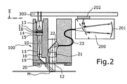
- the spectrophotometer contains a lighting arrangement with a spectral essentially continuous illumination light source comprising several individual light sources and optical means in order to ensure that the light sources To direct light separately onto the sample to be measured, a collection arrangement for Detection of the measuring light emanating from a measuring spot of the sample, a spectrometer (spectral analyzer) for the decomposition of the measured light into its spectral Shares and an electronic circuit for control and signal processing.
- the spectrophotometer comprises an optical measuring head 100, Spectrometer 200 and a circuit board 300, which the measuring head and the spectrometer mechanically and electrically connects and the entire electronic circuit for controlling the measuring head and the spectrometer.
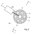
- the measuring head 100 comprises an externally essentially cylindrical housing 10, in which several, evenly distributed around the optical axis A, are shown Example six continuous lighting channels 11 are arranged. Furthermore is in the measuring head 100 axially a (in the drawing) downwardly open collecting channel 12 intended. The six lighting channels 11 and the collecting channel 12 are on their (in the drawing) lower end covered by a transparent pane 20 and so protected from pollution.
- the housing 10 of the measuring head 100 is designed that the disc 20 is easily accessible and can be cleaned.
- each lighting channel 11 there is an upper end (in the drawing) as a light-emitting diode (LED) designed light source 13, which is electrically on the circuit board 300 is mounted. Furthermore, there are one in each lighting channel 11 Field diaphragm 14, a condenser lens 15, an imaging lens 16, a lens 17, one or more filters 18 and a deflecting mirror 19.
- the optical Components 13-19 are sized and arranged so that each LED light source 13 a coaxial measuring spot M des located below the measuring head 100 Measurement object illuminated at an illumination angle of essentially 45 °.
- the lenses 17 and / or the filters 18 can be used depending on the type LEDs 13 and the intended use of the spectrophotometer are also omitted.
- the (here six) light sources 13 implemented as LEDs together form a spectral essentially continuous illuminating light source.
- a collecting lens 21 and a deflecting mirror 22 are located in the collecting channel 12. These two components collect the remitted or emitted by the measurement spot M. Pair the measuring light at an observation angle of essentially 0 ° it into an optical fiber 23 leading out of the side of the measuring head. This directs the collected measurement light into the spectrometer 200, where it is known per se Way is broken down into its spectral components.
- the spectrometer 200 is e.g. according to EP-A 1 041 372 constructed and contains a diffraction grating as the dispersing optical element 201 and as a light sensor a diode array 202, the latter is preferably arranged so that it is mounted directly on the circuit board 300 (Fig. 3).
- the diode array 202 generates electrical in a manner known per se Signals that correspond to the spectral components of the measurement light received.
- the measuring principle used for the spectrophotometer according to the invention is based on the known concept of a (spectrally) continuous light source and one Collection channel with a connected spectral analyzer (spectrometer). This measuring principle enables high spectral resolution and fast at the same time Measurement cycles.
- the measuring principle can be used simultaneously for remission measurements in a manner known per se with the lighting arranged in the measuring head and for emission measurements be used on self-candlesticks.
- LED Semiconductor luminescent diodes
- LED 13 are used.
- Such white LEDs have recently become commercially available from various manufacturers. These LEDs generate the white continuous lighting spectrum by means of luminescence conversion. They are made up of an LED chip, which light in the blue, violet or UV spectral range emitted.
- fluorescent in the LED housing Pigment layers used which by the emitted by the LED chip Light can be optically excited and re-emit light of a longer wavelength.
- the structure and function of white luminescence LEDs are for Example in the publication "White Light Emitting Diodes" by J. Bauer, P. Schlotter, and J. Schneider in R. Helbig (Ed.) Fest stressesprobleme, Vol. 37, Braunschweig: Vieweg, 1998, pp. 67-78.
- White LEDs offer compared to conventional broadband light sources, such as Incandescent or flash lamps, basic advantages in spectrophotometers.
- LEDs have a long lifespan of typically 50,000 hours, so that Measuring system can be easily set up without a replaceable lighting unit can.
- White LEDs generate a limited range of the visible spectral range Spectrum. For this reason, no additional band limitation filters are required in the collecting channel installed for a spectral measurement with a grating spectrometer become. LEDs have good efficiency, so they have low electrical Power can be operated and generate little heat. You can also LEDs are operated with a short pulse.
- LEDs are also ideal light sources for the Combination with plastic optics.
- Optical components made of plastic can be used in placed in close proximity to the light source or even firmly connected to the light source become. This enables compact design, light weight and low Production costs.
- mechanical Positioning aids for the LED light sources can be integrated. This makes possible simple assembly during production without active adjustment of the light source compared to the lighting optics.
- the electronic circuit and the LED light sources 13 mounted on a common circuit board 300.
- the LEDs are used in standard housings.
- the lighting is made up of several LED light sources, which in the Measuring head 100 or on the circuit board 300 in a ring shape and concentrically opposite the collecting channel 12 are arranged.
- the lighting system implements a two-stage imaging system for each LED 13.
- the light of each individual LED 13 is first through the (optional) filter 18 guided.
- This filter 18 is used to determine the emission spectrum of the LED 13 for the desired one
- Optimally adapt application e.g. um in the detector 202 of the spectrometer 200 a constant electrical measurement signal over the spectral measuring range to reach.
- the diffusing screen arranged in the beam path after the LED light source 13 17 mixes the light rays angularly, because the radiation characteristics of a white one LED is not spectrally constant.
- the field diaphragm 14 limits the spatial extent of the illumination spot in the Measuring field M.
- the first condenser lens 15 detects the light from the light source 13 and generates it an intermediate image of the light source.
- a second imaging system consisting of the combination of imaging lens 16 and deflecting mirror 19 then generated in Measuring field M under a certain angle of incidence (here 45 °) a limited illumination spot.
- optical components in the lighting system (condenser lens 15, imaging lens 16) formed from integral annular plastic components, which simultaneously integrate all lenses of the individual lighting channels. This reduces the manufacturing costs and simplifies assembly.
- the converging lens 21 focuses the light onto the optical one Optical fiber 23, which is arranged in the focal point of the converging lens 21.
- the optical fiber leads the measuring light to the spectrometer 200.
- the coupling in the spectrometer 200 can also directly through an entry slit without optical fiber will be realized.
- the spectrometer as realized in EP-A 1 041 372 as a plastic diode line grating spectrometer.
- the collecting channel 12 is preferably as designed telecentric imaging system (see Fig. 7).
- the measuring field sharply imaged by a first lens 21a in a telecentric arrangement.
- an aperture 24 is attached, which sharply delimits the measuring field.
- second lens system 21b couples the light into the spectrometer.
- the coupling can also enter the spectrometer directly via an entry slit or can be realized by means of an optical fiber 23.
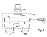
- the electronic circuitry on circuit board 300 includes, like the figure 4 shows a computer-based controller 310, a driver stage 320 for the selective Control of all LED light sources 13, a driver stage 330 for control the diode array 202 and an interface 340 for communicating with an external computer 400.Operating elements (e.g. buttons) 410 are also optional provided for communication with the controller 310.
- the electronic circuit the spectrophotometer is so far essentially conventional and controls the measurement sequence in a manner known per se, the determined Measured values are communicated to the external computer via the interface 340. As is known per se, the external computer can also control the measurement process.
- the Electronic circuitry also regulates the operation of the LED light sources 13. The light emission of the LEDs 13 is controlled according to known methods, e.g. as in the book "Optoelectronics / Fiberoptics Applications Manual" 2nd Edition by Hewlett-Packard Company, Optoelectronics Division, Applications Engineering Staff, 1981, pages 2.1 to 2.55.
- the spectrophotometer according to the invention described above can be further expanded by using not only white LEDs, but also differently colored LEDs as light sources 13 are used. This enables the realization of different ones particularly advantageous developments or variants of the spectrophotometer, which are described below.
- the first further training concerns the realization of an electronically switchable UV Light source.
- This light source is realized by several white light sources 13 LEDs and additional UV LEDs can be installed. Emit UV LEDs Mainly light in the ultraviolet spectral range between 350 nm and 420 nm.
- the electronic control and regulation of the LED light source is designed so that the emitted intensity of each individual LED 13 separately (or in groups) can be adjusted. This allows in the overlaid, total lighting spectrum the percentage of UV light compared to the visible Light spectrum can be varied.
- This procedure enables a variable, electronic controllable fluorescence excitation of optical brighteners in the one to be measured Sample.
- This variant corresponds to an electronically controllable UV filter in the Illumination optics, but no mechanically moving components are required are.
- defined types of light for example, those of the CIE defined standard light types
- real light sources with different UV Proportion in the measuring head can be simulated, which is the measurement of color values with correct Fluorescence evaluation of optical brighteners enabled.
- the consideration real lighting sources in color measurement technology gives a big advantage for digital visualization and test applications in color management.
- spectrophotometer includes the Realization of an additionally precise spectrally measuring density measuring head.
- additional functionality in addition to the white LEDs (at least) 3 colored LEDs used, which only in red, green or blue Radiate spectral range.
- the electronic circuit 310-340 can do various pre-defined density filter functions as spectral Contain value tables, on the basis of which they select the desired ones from the spectral measurement signals Density values calculated. Digital filtering or calculation of density values can of course also be done using an application program, which runs in an external computer connected to the densitometer.
- the white light source When used as a pure color densitometer, the white light source can of course be used omitted. Special protection is also required for this training as a densitometer.
- a third development of the spectrophotometer according to the invention relates to Realization of a spectrophotometer with an electronically variable light source.
- a continuous lighting spectrum over the visible and ultraviolet Spectral range can also be achieved by a combination of several narrowband radiating LEDs can be achieved.
- LEDs have typical spectral half-widths from 20 - 50 nm.
- For a spectrum of continuous over the visible range 400 - 700 nm therefore have about 8 different LEDs in a common ring lighting be used analogously to Fig. 1-3. If in a certain spectral range No narrowband LEDs can be found, broadband LEDs can be found in Combination with appropriate filters can be used.
- the lighting spectrum can be in the spectrophotometer over the entire spectral measuring range to a desired theoretical or measured Lighting distribution can be adjusted.
- This electronically adjustable Light source enables correct color evaluation for general fluorescent colors. The measurement process can be done with a single measurement with all LEDs on Condition.
- spectrophotometer also enables the realization of a simple compact double monochromator spectrophotometer.
- this application is controlled by appropriate control of the LEDs for each independent spectral range of the light source formed by the various LEDs sequentially one spectral measurement performed. These multiple measurements allow the lowest Scattered light level and a general assessment of fluorescence effects.
- the color measurement of effect color layers must be with a multi-angle measurement geometry be carried out.
- the control and description of the angle dependent Color behavior of effect color layers requires measurement with at least 3 characteristic ones (Illumination) angles, which are described, for example, in the ASTM standards E 284 (15 °, 45 °, 110 °) and DIN 6175-2 (25 °, 45 °, 75 °) are specified.
- FIGS. 5 and 6 show a second exemplary embodiment of the one according to the invention Spectrophotometer outlines which one for multi-angle measurements (here in the example 25 °, 45 ° and 75 °).
- the measuring head 100 has the same structure as that of the exemplary embodiment of Figures 1-3, but contains not only one, but three concentric annular Arrangements of lighting channels, which are designated by 11a, 11b and 11c are.
- Each lighting channel in turn contains an LED light source, one Lens (optional), a filter (optional), a field diaphragm, a condenser lens, an imaging lens and a deflecting mirror, those corresponding to those in FIG. 1 Parts in the lighting channels with the same reference numerals, but in Corresponding to their belonging to one of the three annular arrangements of Illumination channels 11a, 11b, 11c marked with additional indices a, b and c are. All other parts of the spectrophotometer are identical or analog as those of the embodiment of Figures 1-4.
- each annular arrangement of lighting channels 11a, 11b, 11c this is Light from at least one white LED and possibly additional LEDs (single color, UV) coupled in and at the outlet at a defined angle (here in Example 25 °, 45 ° and 75 °) directed onto the measuring field.
- the geometry of each ring-shaped Arrangement can be designed variably, i.e. any "ring" arrangement can include a different number of lighting channels. Accordingly light falls out for each illumination angle (relative to the optical axis A) one or more (radial) directions on the sample.
- the measurement geometry is designed so that no optical crosstalk between the channels with different Illumination angle including the associated LED light sources can take place.
- each LED light source is provided with a two-stage imaging system consisting of the condenser lens and the imaging lens mapped in the common measuring field M.
- the optical imaging system also includes the field diaphragm, which is the size of the lighting spot defined in the measuring field and possibly additional filters and the lens.
- the angle of illumination the measuring field is in each lighting channel through the deflecting mirror Are defined.
- the diameter of the field diaphragm of each lighting channel must be adjusted according to the cosine of the lighting angle in order to to illuminate the same-sized measuring field. This requires at large lighting angles small aperture diameter and means loss of light. This loss of light can by using a larger number of LEDs in the corresponding lighting channels be compensated
- Figures 5-6 enables the positioning of all LED light sources at the same height above the measuring field. This enables easy Installation of all LEDs in standard housings on the common 300 circuit board.
- the two lenses are in all Illumination channels implemented at the same height above the measuring field. This requires that the focal lengths of the two lenses in each lighting channel on the mutual positions of the lighting channels are coordinated.
- This special arrangement offers fundamental advantages for the production of the Spectrophotometer.
- the normally difficult adjustment of a multi-channel lighting system so that the light of all lighting channels is clean in the common Measurement field can be easily solved with this arrangement.
- the condor lenses and the imaging lenses of all lighting channels are used to as shown in FIG. 5, realized as a physically integrated (one-piece) lens array. This reduces manufacturing costs, since only one component is made, for example Plastic has to be injection molded. In addition, through the integration on one element an exact mutual positioning of the lenses reached. In addition, there are mechanical positioning structures in the lens arrays (e.g. in the form of recesses) integrated with corresponding position structures (e.g. in the form of ridges or pegs) work together in the measuring head housing and thus allow an adjustment-free assembly of the measuring head.
- mechanical positioning structures in the lens arrays e.g. in the form of recesses
- corresponding position structures e.g. in the form of ridges or pegs
- the housing of the measuring head 100 essentially consists of three parts 10a, 10b and 10c, which are each provided with peg-shaped position structures 30a, 30b, 30c.
- An upper housing part 10a contains the holders for the LED light sources and is on the condenser lens array 15a-15c by means of the positioning structures 30a plugged.
- a middle part 10b serves as a spacer to the lens array of the converging lenses 16a-16c. It is provided with the positioning structures 30b and by means of these with the two Lens arrays 15a-15c and 16a-16c connected.
- the LED light sources are operated briefly in a pulsed manner, so that only the LEDs belonging to one lighting angle are activated sequentially in time and the corresponding reflection spectrum under the relevant lighting angle is detected.
- the lighting system of the measuring head is designed so that at least one lighting channel the measuring field is illuminated at an angle of 45 °.
- additional Lighting channels are ideally lighting angles corresponding to the Standards for multi-angle color measurement devices (e.g. ASTM E 284 and DIN 6175-2) implemented.
- the color measuring system must have a contactless measuring geometry between the measuring head and the sample will be realized.
- the 45 ° / 0 ° and multi-angle measurement geometries are because of the large ones Illumination angle very sensitive to changes in distance.
- US-A 6198536 is a complex mechanical Construction provided for a constant measuring distance during the measuring process provides. Such constructions are complex and not generally for built-in sensors applicable.
- one in the measuring head Integrated optical distance measurement and numerical correction of the measured values to compensate for the influence of distance fluctuations during measuring operation used.
- This compensation technology makes significantly larger ones Limit values for tolerable distance fluctuations reached, so that an easier mechanical construction can be used for the installation of the sensor.
- FIG. 7 A first variant for a distance measurement integrated in the measuring head is shown in FIG. 7 shown schematically.
- the optical distance measurement is based on a trigonometric measuring method.
- a change in the measuring distance caused due to the large lighting angle a lateral offset of the illumination spot with respect to the measuring field of the collecting channel.
- This lateral offset produces a change in the signal level and leads to measurement errors.
- the lateral offset of the lighting spot is measured and used numerical correction evaluated.
- the collecting channel 12 is designed in such a way that it maps the measuring field enables an optical sensor 26.
- a first lens 21a generates an intermediate image in the collecting channel.
- a Aperture 24 is arranged in the focal point of the first lens 21a and limits the detection angle of the measuring field.
- the optical beam path with a beam splitter 25 divided.
- the major part of the measuring light is with a second lens 21b coupled into the optical fiber 23 and via this the spectrometer 200 (Fig.2) fed.
- a small proportion is used to measure the in the lateral offset in the image plane of the measuring field to be able to measure.
- the optical sensor 26 can be, for example, two-dimensional Image sensor (CCD chip), as a position-sensitive detector (PSD) or as a 4-quadrant detector be formed., The determination of the lateral offset by means of the sensor 26 according to methods known per se.
- the corresponding relative signal changes for certain offset values measured and saved.
- the correction factors become from these values determined for the measured values during the measuring operation. This can be done using numerical Interpolation between the stored values.
- the correction the measurement data does not have to be carried out in the spectrophotometer itself. she can also be carried out in an external computer, which only measures the measured values received from the spectrophotometer.
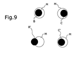
- FIGS. 8-9 An alternative implementation of the distance measurement principle is through the installation two lighting channels 111a and 111b, which the measuring field below Illuminate at the same angle, but create two laterally offset lighting spots. This variant is shown schematically in FIGS. 8-9. With M is that designated by the collecting channel 12 measuring spot on the sample to be measured, B and C or B 'and C' denote those of the two lighting channels 111a and 111b created illumination spots at two different distances.
- the two lighting spots B and C shift compared to the measuring field M. Because of the lateral offset, a different Signal changes when measuring each individual lighting channel with the spectral collecting channel reached.
- the ratio of these two measurement signals is one characteristic size for the change in distance. This ratio can be adjusted during calibration of the spectrophotometer can be measured as a function of the change in distance and a corresponding signal level correction.
- This second Realization has the advantage that the same optical components for the color and the distance measurement can be used.
- the color management is a color chart that shows the color space of a printing system well represents, spectrally with the multi-angle spectrophotometer according to the invention calibrated.
- the reflectance spectra of each angle of illumination stored.
- the reflectance spectra can be converted into color values (CIE XYZ or L * a * b *).
- multi-angle device color profiles are created. For easy use in standard color management systems is for everyone Measuring angle created a device profile corresponding to the ICC definition. This device profile corresponds to a table that corresponds to the measured system control signals Assigns color values. Missing color values are due to interpolation between the measured values in the table.
- These multiple profiles can be in one ICC-compatible image processing software, for example Photoshop from the company Adobe, loaded and used to change the angle-dependent color properties a digital image or document, which according to a specified printing process reproduced to display on the screen.
Abstract
Description
Die Erfindung betrifft ein Spektralphotometer gemäss dem Oberbegriff des unabhängigen Anspruchs sowie die Verwendung bzw. den Einsatz eines solchen Spektralphotometers.The invention relates to a spectrophotometer according to the preamble of the independent Claim and the use or use of such a spectrophotometer.
In modernen digitalen Arbeitsabläufen für die Reproduktion von farbigen Dokumenten, Bildern und Verpackungen nimmt das Desktop Publishing und das Color Management einen immer wichtigeren Stellenwert ein. Im Desktop Publishing erarbeitet der Designer auf seinem Computer in elektronischer Form heute nicht nur das graphische Konzept und die Farbgestaltung, sondern spezifiziert auch immer mehr reproduktionstechnische Parameter betreffend der letztendlichen Herstellung und Vervielfältigung des Dokuments, wie z. B. das Druckverfahren, die Papierqualität oder Spezialfarben. Da Testdrucke teuer und zeitaufwendig sind, ist es für diese Anwendung erwünscht, dass der Designer die Farbwiedergabeeigenschaften seines elektronischen Entwurfs gemäss einem speziellen Druckprozess simulieren und prüfen kann.In modern digital workflows for the reproduction of colored documents, Desktop publishing and color management take pictures and packaging an increasingly important role. Developed in desktop publishing the designer on his computer in electronic form today not only the graphic Concept and the color scheme, but also increasingly specifies reproductive technology Ultimate production and duplication parameters of the document, such as B. the printing process, paper quality or special colors. Since test prints are expensive and time consuming, it is for this application wishes the designer to change the color rendering properties of his electronic Can simulate and test the design according to a special printing process.
Die Kommunikation und Reproduktion von konsistenten Farben werden durch den Einsatz von Color Management Technologien ermöglicht. In einem Color Management System (CMS) werden die am Workflow beteiligten Ein- und Ausgabesysteme durch den Einsatz von Farbmessgeräten farbmetrisch kalibriert und charakterisiert. Der Zusammenhang zwischen absoluten Farbmesswerten und systemspezifischen Farbsteuersignalen wird in sogenannten Geräteprofilen gespeichert. Durch die Kombination von Geräteprofilen kann Farbinformation medien- und systemübergreifend kommuniziert und reproduziert werden.The communication and reproduction of consistent colors are through the Use of color management technologies. In a color management System (CMS) become the input and output systems involved in the workflow colorimetrically calibrated and characterized by the use of color measuring devices. The relationship between absolute color measurement values and system-specific Color control signals are stored in so-called device profiles. Through the combination Device information can provide color information across media and systems communicated and reproduced.
Der Aufbau bestehender Color Management Systeme ist vom ICC (International Color Council) normiert und beschrieben worden (siehe z.B. http://www.imaging.org für die neueste Version des ICC Standards ) und ist auch in der von der Firma Logo GmbH, einer Gesellschaft der GretagMacbeth Gruppe, im August 1999 herausgegebenen Publikation "Postscriptum on Color Management, Philosophy and Technology of Color Management" der Autoren Stefan Brües, Liane May und Dietmar Fuchs zusammengefasst. The structure of existing color management systems is from the ICC (International Color Council) have been standardized and described (see e.g. http://www.imaging.org for the latest version of the ICC standard) and is also in the company logo GmbH, a company of the GretagMacbeth Group, published in August 1999 Publication "Postscriptum on Color Management, Philosophy and Technology of Color Management "by the authors Stefan Brües, Liane May and Dietmar Fuchs.
Durch den Einsatz von Color Management und Geräteprofilen erhält der Designer die Möglichkeit, die Farbwiedergabe von verschiedenen Druckverfahren auf seinem Bildschirm zu visualisieren oder mit einem digitalen Drucker zu simulieren. Allerdings sind die Möglichkeiten und die Genauigkeit solcher digitalen Prüfmethoden zur Zeit beschränkt. Schwierigkeiten für eine korrekte Visualisierung bereiten material- oder prozessspezifische Parameter, welche die visuelle Farbwahrnehmung beeinflussen, aber mit den aktuell verwendeten Farbmessgeräten nicht oder nur schlecht erfasst werden. Typische Beispiele sind Substratmaterialien mit unterschiedlichen Oberflächeneigenschaften, optischen Aufhellern oder fluoreszierende Farben.By using color management and device profiles, the designer receives the Possibility of color rendering of various printing processes on his screen to visualize or simulate with a digital printer. Indeed are the possibilities and the accuracy of such digital test methods at the moment limited. Difficulties for a correct visualization cause material or process-specific parameters that influence the visual color perception, but not or only poorly recorded with the currently used color measuring devices become. Typical examples are substrate materials with different surface properties, optical brighteners or fluorescent colors.
Proben von gleicher Farbe aber mit unterschiedlichen Oberflächeneigenschaften sehen unterschiedlich aus. Eine Probe mit einer glänzenden Oberfläche wird dunkler und farblich gesättigter wahrgenommen als mit einer diffus reflektierenden Oberfläche.See samples of the same color but with different surface properties different. A sample with a shiny surface becomes darker and perceived in a more saturated color than with a diffusely reflecting surface.
Die Wirkung von optischen Aufhellern und fluoreszierenden Farben hängt stark vom Beleuchtungsspektrum ab. Für eine korrekte Bewertung muss die Lichtquelle im Messgerät an die reellen Betrachtungsbedingungen angepasst werden können.The effect of optical brighteners and fluorescent colors depends heavily on Lighting spectrum. For a correct evaluation, the light source in the Measuring device can be adapted to the real viewing conditions.
Von steigender Bedeutung für Verpackungen und Werbung sind auch auf Metallicaoder Perlglanzpigmenten basierende, sogenannte Effektfarbschichten. Diese zeichnen sich dadurch aus, dass sie starke beleuchtungs- oder betrachtungswinkelabhänge Reflektionseigenschaften aufweisen. Eine Beschreibung von Effektfarbschichten ist zum Beispiel in den Artikeln "Pigmente - Farbmittel und Funktionsträger" von C. D. Eschenbach und "Perlglanzpigmente" von G. Pfaff im Spektrum der Wissenschaft, Oktober 1997, S.94-99 und S. 99-104 gegeben. Solche winkelabhängigen Spezialeffekte können zur Zeit nicht innerhalb eines Color Management Systems erfasst werden.Metallica or are also of increasing importance for packaging and advertising Pearlescent pigments based, so-called effect color layers. Draw this is characterized by the fact that they have strong lighting or viewing angle-dependent reflection properties exhibit. A description of effect color layers is for Example in the articles "Pigments - Colorants and Functional Carriers" by C. D. Eschenbach and "Pearlescent Pigments" by G. Pfaff in the spectrum of science, October 1997, pp. 94-99 and pp. 99-104. Such angle-dependent special effects cannot currently be recorded within a color management system.
Auch bei bedruckten metallisch glänzenden Substratmaterialien oder Folien tritt ein starker winkelabhängiger Oberflächenglanz auf, welcher für eine korrekte Darstellung messtechnisch erfasst werden muss.Also occurs with printed metallic shiny substrate materials or foils strong angle-dependent surface gloss, which ensures correct display must be recorded by measurement.
Für die Anwendung als Einbausensor muss ein Messsystem folgende Grundanforderungen erfüllen: Es muss schnelle Messzyklen erlauben, eine kompakte Bauform und geringes Gewicht aufweisen, robust sein und eine lange Lebensdauer aufweisen, und es muss möglichst wartungsfrei sein. Ausserdem muss ein Messsystem, um im online oder inline Betrieb in einem automatisierten System eingesetzt werden zu können, eine kontaktlose Messgeometrie zur Probe ermöglichen.A measuring system must meet the following basic requirements for use as a built-in sensor fulfill: It must allow fast measuring cycles, a compact design and have low weight, be robust and have a long service life, and it must be as maintenance-free as possible. In addition, a measurement system must be in order to be online or to be used inline in an automated system, enable a contactless measurement geometry to the sample.
Für Color Management Anwendungen im graphischen Bereich werden heutzutage Farbmessgeräte mit 45°/0° oder 0°/45° Messgeometrie eingesetzt, welche in kompakter Bauweise realisiert sind. Als typisches Beispiel sei das Spektralphotometer "Spectrolino" der Firma Gretag-Macbeth AG und die EP-A 1 067 369 angeführt. Die verwendete Messtechnik basiert auf einer Glühlampe als Beleuchtungsquelle und einem Diodenzeilen-Gitter-Spektrometer für die spektrale Auswertung im Messkanal. Das "Spectrolino" Spektralphotometer kann als Messkopf auf einen xy-Verschiebetisch, z.B. den Typ "SpectroScan" der Firma Gretag-Macbeth AG aufgesteckt werden, was das automatisierte Ausmessen einer grossen Anzahl von Farbproben für die Erstellung eines Drucker-Geräteprofils ermöglicht.For color management applications in the graphic field today Color measuring devices with 45 ° / 0 ° or 0 ° / 45 ° measuring geometry used, which in a more compact Construction are realized. The spectrophotometer is a typical example "Spectrolino" from Gretag-Macbeth AG and EP-A 1 067 369. The Measurement technology used is based on an incandescent lamp as a lighting source and one Diode line grating spectrometer for spectral evaluation in the measuring channel. The "Spectrolino" spectrophotometer can be used as a measuring head on an xy sliding table, e.g. the type "SpectroScan" from Gretag-Macbeth AG is plugged on, what is the automated measurement of a large number of color samples for the creation a printer device profile.
Die im "Spectrolino" verwendete Messtechnik ist aus verschiedenen Gründen nicht für den Einsatz als Einbausensor geeignet. Die Glühlampe hat eine begrenzte Lebensdauer. Das Messsystem muss deshalb speziell für einen einfachen Lampenwechsel ausgelegt sein. Die Wendel der Glühlampe ist empfindlich auf Vibrationen, was beim Einbau in motorisierte Systeme Schwierigkeiten bereitet. Das Messsystem ist auch empfindlich auf Distanzschwankungen zwischen Probe und Messoptik. Deshalb wird bei diesen Geräten in direktem mechanischem Kontakt mit der Probe gemessen.The measuring technology used in the "Spectrolino" is not for various reasons suitable for use as a built-in sensor. The light bulb has a limited lifespan. The measuring system must therefore be specially designed for a simple lamp change be designed. The filament of the incandescent lamp is sensitive to vibrations, which when Installation in motorized systems is difficult. The measuring system is too sensitive to distance fluctuations between sample and measurement optics. That is why measured with these devices in direct mechanical contact with the sample.
Der Einsatz eines Farbmessgeräts mit 45°/0° Messgeometrie in digitalen Drucksystemen für Color Management Anwendungen ist z.B. in der DE-C 197 22 073 beschrieben.The use of a color measuring device with 45 ° / 0 ° measuring geometry in digital printing systems for color management applications e.g. described in DE-C 197 22 073.
Winkelabhängige Reflektionseigenschaften können mit der 45°/0° Geometrie nicht erfasst werden. Für die Bewertung von Materialparametern, wie Oberflächeneffekt und Fluoreszenzanregung von optischen Aufhellern, können in dieser Geometrie bekannte Verfahren mit zusätzlich im Beleuchtungs- und Messkanal einschwenkbaren optischen Filtern angewandt werden. Für die Elimination des Oberflächeneffekts kann eine Messung mit gekreuzten linearen Polarisationsfiltern und für die Fluoreszenzanregung können Lichtartkonversionsfilter eingesetzt werden. Für automatisierte Messsysteme muss diese Funktionalität mit mechanisch bewegten Baugruppen, zum Beispiel mit einem Filterrad wie im Spektralphotometer "SpectroEye" der Firma Gretag-Macbeth AG realisiert werden. Bewegte mechanischen Komponenten sind für kompakte Sensorsystem nicht geeignet. Angle-dependent reflection properties cannot with the 45 ° / 0 ° geometry be recorded. For the evaluation of material parameters such as surface effect and fluorescence excitation of optical brighteners can be known in this geometry Process with additional swiveling in the lighting and measuring channel optical filters can be applied. For the elimination of the surface effect can a measurement with crossed linear polarization filters and for fluorescence excitation illuminant conversion filters can be used. For automated measuring systems this functionality with mechanically moving assemblies, for example with a filter wheel as in the "SpectroEye" spectrophotometer from Gretag-Macbeth AG can be realized. Moving mechanical components are for compact Sensor system not suitable.
Alternative Techniken in kombinierten Messgeräten für Farb- und Oberflächeneigenschaften basieren auf einer diffusen Messgeometrie mit einer Ulbrichtskugel oder dem Einsatz einer Glanzmessung.Alternative techniques in combined measuring devices for color and surface properties are based on a diffuse measurement geometry with an integrating sphere or the use of a gloss measurement.
In der diffusen Messgeometrie kann eine Glanzfalle in der Ulbrichtskugel eingebaut werden, welche von der Probenoberfläche gerichtet reflektiertes Licht im Messkanal eliminiert. Eine vorteilhafte Auslegung dieses Messprinzips ist beispielsweise in der EP-A 0 964 244 beschrieben. Allerdings muss die diffuse Messgeometrie per definitionem in direktem Kontakt zur Messprobe realisiert werden. Die Messgeometrie mit der Ulbrichtskugel eignet sich nicht für die Miniaturisierung, und die Herstellung einer gut reflektierenden Ulbrichtskugel ist aufwendig. Ausserdem ist die Geometrie mit der Ulbrichtskugel nicht direkt für die Fluoreszenzmessung anwendbar und muss speziell geeicht werden.A gloss trap can be built into the integrating sphere in the diffuse measurement geometry which are reflected light directed from the sample surface in the measuring channel eliminated. An advantageous interpretation of this measuring principle is, for example, in the EP-A 0 964 244. However, the diffuse measurement geometry by definition in direct contact with the measurement sample. The measurement geometry with the integrating sphere is not suitable for miniaturization and the production of a well reflecting integrating sphere is complex. In addition, the geometry with the integrating sphere cannot and must not be used directly for fluorescence measurement are specially calibrated.
In Glanzmessgeräten wird mit einer schmalbandigen Lichtquelle die Probe gerichtet beleuchtet und mit einem Detektor der Anteil des von der Oberfläche direkt gerichtet reflektierten Lichts gemessen. Aus dem Messwert wird ein für die Oberfläche charakteristischer Glanzgrad bestimmt. Dieser Glanzgrad repräsentiert die Oberflächenqualität, aber nicht direkt die visuelle Farbwahrnehmung und ist so für Visualiserungsanwendungen im Color Management Bereich nicht geeignet. Kombinierte Farbmessgeräte mit 45°/0° Messgeometrie und integrierter Glanzmessung sind in USA 5 377 000 und US-A 4 886 355 beschrieben. Ein kommerzielles Produkt mit dieser Funktionalität ist von der Firma BYK-Gardner unter der Bezeichnung "Color-Guide Gloss" erhältlich.The specimen is aligned in gloss meters using a narrow-band light source illuminated and with a detector the proportion of that is directed directly from the surface reflected light measured. The measured value becomes a characteristic of the surface Degree of gloss determined. This degree of gloss represents the surface quality, but not directly visual color perception and is so for visualization applications not suitable for color management. combined Color measuring devices with 45 ° / 0 ° measuring geometry and integrated gloss measurement are in the USA 5,377,000 and US-A 4,886,355. A commercial product with this Functionality is from BYK-Gardner under the name "Color Guide Gloss "available.
Verschiedene Hersteller bieten Multi-Winkel-Spektralphotometer für die Farbmesstechnik an. Als typische Beispiele können die Geräte "MA68IL" der Firma Xrite, "CM512m3" der Firma Minolta sowie "CE640" und "CE740" der Firma Gretag-Macbeth AG genannt werden. Diese Geräte sind teilweise zwar tragbar, weisen aber eine komplexe mechanische Bauform auf und müssen für die Messung mechanisch auf die Probe aufgelegt werden. Diese Systeme sind u.a. auch wegen ihrer Grösse nicht als Einbausensor einsetzbar.Various manufacturers offer multi-angle spectrophotometers for color measurement technology on. As typical examples, the devices "MA68IL" from Xrite, "CM512m3" from Minolta and "CE640" and "CE740" from Gretag-Macbeth AG can be called. Some of these devices are portable, but they do a complex mechanical design and need mechanical for the measurement put on the sample. These systems include also because of their size cannot be used as a built-in sensor.
Ausgehend von diesem Stand der Technik soll durch die vorliegende Erfindung nun ein speziell für Color Management Anwendungen ausgelegtes Spektralphotometer geschaffen werden, welches die vorgenannten Grundanforderungen erfüllt und bei kompakter Bauweise einen vielseitigen Einsatz an allen an einem Color Management System beteiligten Ein- und Ausgabemedien ermöglicht und insbesondere auch als Einbaugerät oder Messsensor in automatisierten Farbmesssystemen oder direkt in Farbdrucksystemen eingesetzt werden kann. Speziell soll das Spektralphotometer zur Messung sowohl von Farbe als auch von Material- und Farbreproduktionseigenschaften und Effektfarbschichten geeignet sein und erlauben, aus den Messresultaten Geräteprofile der unterschiedlichsten Art zu bilden und so eine genaue Visualisierung der Farbreproduktionseigenschaften eines Herstellungsprozesses zu ermöglichen.Based on this state of the art, the present invention is now intended a spectrophotometer specially designed for color management applications be created, which meets the aforementioned basic requirements and at compact design a versatile use on all color management System involved input and output media enables and especially as Built-in device or measuring sensor in automated color measuring systems or directly in Color printing systems can be used. Specifically, the spectrophotometer should Measurement of color as well as material and color reproduction properties and effect color layers may be suitable and allow, from the measurement results To form device profiles of the most different kind and thus an exact visualization to enable the color reproduction properties of a manufacturing process.
Die Lösung dieser der Erfindung zugrundeliegenden Aufgaben ergibt sich durch das erfindungsgemässe Spektralphotometer gemäss den kennzeichnenden Merkmalen des unabhängigen Anspruchs. Besonders zweckmässige und vorteilhafte Ausgestaltungen sind Gegenstand der abhängigen Ansprüche.The solution to the problems underlying the invention results from Spectrophotometer according to the invention according to the characterizing features of the independent claim. Particularly expedient and advantageous configurations are the subject of the dependent claims.
Im folgenden wird die Erfindung anhand der Zeichnung näher erläutert. Es zeigen:
- Fig. 1
- einen Axialschnitt durch ein erstes Ausführungsbeispiel des erfindungsgemässen Spektralphotometers nach der Linie I-I der Fig. 3,
- Fig. 2
- einen Axialschnitt nach der Linie II-II der Figur 3,
- Fig. 3
- einen Querschnitt nach der Linie III-III der Fig. 1,
- Fig. 4
- ein Prinzipschema der elektronischen Komponenten des erfindungsgemässen Spektralphotometers,
- Fig. 5
- einen Axialschnitt analog Fig. 1 durch ein zweites Ausführungsbeispiel des erfindungsgemässen Spektralphotometers,
- Fig. 6
- einen Querschnitt analog Fig. 3 nach der Linie VI-VI der Fig. 5,
- Fig. 7
- eine Prinzipskizze zur Erläuterung einer ersten Variante einer integrierten Abstandsmessung und
- Fig. 8-9
- zwei Prinzipskizzen zur Erläuterung einer zweiten Variante einer integrierten Abstandsmessung.
- Fig. 1
- 3 shows an axial section through a first exemplary embodiment of the spectrophotometer according to the invention along the line II in FIG. 3,
- Fig. 2
- 3 shows an axial section along the line II-II in FIG. 3,
- Fig. 3
- 2 shows a cross section along the line III-III of FIG. 1,
- Fig. 4
- a schematic diagram of the electronic components of the spectrophotometer according to the invention,
- Fig. 5
- 2 shows an axial section analogous to FIG. 1 through a second exemplary embodiment of the spectrophotometer according to the invention,
- Fig. 6
- 3 along the line VI-VI of FIG. 5,
- Fig. 7
- a schematic diagram to explain a first variant of an integrated distance measurement and
- Fig. 8-9
- two sketches to explain a second variant of an integrated distance measurement.
Der prinzipielle Aufbau des in seiner ersten Ausführungsform auf eine 45°/0°-Messgeometrie ausgelegten Spektralphotometers ist in den Figuren 1-3 dargestellt. Das Spektralphotometer enthält dabei eine Beleuchtungsanordnung mit einer spektral im wesentlichen kontinuierlichen, mehrere Einzellichtquellen umfassenden Beleuchtungslichtquelle und optischen Mitteln, um das von den Einzellichtquellen ausgehende Licht separat auf die auszumessende Probe zu lenken, eine Sammelanordnung zur Erfassung des von einem Messfleck der Probe ausgehenden Messlichts, ein Spektrometer (spektralen Analysator) zur Zerlegung des erfassten Messlichts in seine spektralen Anteile und eine elektronische Schaltung zur Steuerung sowie zur Signalverarbeitung.The basic structure of the in its first embodiment on a 45 ° / 0 ° measurement geometry designed spectrophotometer is shown in Figures 1-3. The spectrophotometer contains a lighting arrangement with a spectral essentially continuous illumination light source comprising several individual light sources and optical means in order to ensure that the light sources To direct light separately onto the sample to be measured, a collection arrangement for Detection of the measuring light emanating from a measuring spot of the sample, a spectrometer (spectral analyzer) for the decomposition of the measured light into its spectral Shares and an electronic circuit for control and signal processing.
Im einzelnen umfasst das Spektralphotometer einen optischen Messkopf 100, ein
Spektrometer 200 und eine Leiterplatte 300, welche den Messkopf und das Spektrometer
mechanisch und elektrisch verbindet und die gesamte elektronische Schaltung
für die Ansteuerung des Messkopfs und des Spektrometers enthält.In particular, the spectrophotometer comprises an
Der Messkopf 100 umfasst ein äusserlich im wesentlichen zylindrisches Gehäuse 10,
in welchem rund um die optische Achse A gleichmässig verteilt mehrere, im gezeigten
Beispiel sechs durchgehende Beleuchtungskanäle 11 angeordnet sind. Ferner ist
im Messkopf 100 axial ein (in der Zeichnung) nach unten offener Sammelkanal 12
vorgesehen. Die sechs Beleuchtungskanäle 11 und der Sammelkanal 12 sind an ihrem
(in der Zeichnung) unteren Ende durch eine transparente Scheibe 20 abgedeckt und so
vor Verschmutzung geschützt. Das Gehäuse 10 des Messkopfs 100 ist so ausgelegt,
dass die Scheibe 20 leicht erreichbar ist und gereinigt werden kann.The measuring
In jedem Beleuchtungskanal 11 befindet sich am (in der Zeichnung) oberen Ende eine
als Leuchtdiode (LED) ausgebildete Lichtquelle 13, welche elektrisch an der Leiterplatte
300 montiert ist. Ferner befinden sich in jedem Beleuchtungskanal 11 je eine
Feldblende 14, eine Kondensorlinse 15, eine Abbildungslinse 16, eine Streuscheibe
17, ein oder mehrere Filter 18 und ein Umlenkspiegel 19. Die genannten optischen
Komponenten 13-19 sind so bemessen und angeordnet, dass jede LED-Lichtquelle 13
einen unterhalb des Messkopfs 100 befindlichen koaxialen Messfleck M des
Messobjekts unter einem Beleuchtungswinkel von im wesentlichen 45° beleuchtet.
Die Streuscheiben 17 und/oder die Filter 18 können je nach Art der verwendeten
Leuchtdioden 13 bzw. Einsatzzweck des Spektralphotometers auch entfallen. Die
(hier sechs) als LED implementierten Lichtquellen 13 bilden zusammen eine spektral
im wesentlichen kontinuierliche Beleuchtungslichtquelle. In each
Im Sammelkanal 12 befindet sich eine Sammellinse 21 und ein Umlenkspiegel 22.
Diese beiden Komponenten sammeln das vom Messfleck M remittierte oder emittierte
Messlicht unter einem Beobachtungswinkel von im wesentlichen 0° und koppeln
es in eine seitlich aus dem Messkopf herausführende Lichtleitfaser 23 ein. Diese
leitet das aufgefangene Messlicht in das Spektrometer 200, wo es in an sich bekannter
Weise in seine spektralen Anteile zerlegt wird. Das Spektrometer 200 ist z.B. gemäss
EP-A 1 041 372 aufgebaut und enthält als dispersierendes optisches Element ein Beugungsgitter
201 und als Lichtsensor eine Diodenzeilenanordnung 202, wobei letztere
vorzugsweise so angeordnet ist, dass sie direkt auf der Leiterplatte 300 montiert ist
(Fig. 3). Die Diodenzeilenanordnung 202 erzeugt in an sich bekannter Weise elektrische
Signale, die den spektralen Anteilen des empfangenen Messlichts entsprechen.A collecting
Das verwendete Messprinzip des erfindungsgemässen Spektralphotometers beruht auf dem an sich bekannten Konzept einer (spektral) kontinuierlichen Lichtquelle und einem Sammelkanal mit einem angeschlossenen spektralen Analysator (Spektrometer). Dieses Messprinzip ermöglicht gleichzeitig hohe spektrale Auflösung und schnelle Messzyklen. Das Messprinzip kann in an sich bekannter Weise gleichzeitig für Remissionsmessungen mit der im Messkopf angeordneten Beleuchtung und für Emissionsmessungen an Selbstleuchtern verwendet werden.The measuring principle used for the spectrophotometer according to the invention is based on the known concept of a (spectrally) continuous light source and one Collection channel with a connected spectral analyzer (spectrometer). This measuring principle enables high spectral resolution and fast at the same time Measurement cycles. The measuring principle can be used simultaneously for remission measurements in a manner known per se with the lighting arranged in the measuring head and for emission measurements be used on self-candlesticks.
Für die Realisierung der kontinuierlichen Lichtquelle werden gemäss einem wesentlichen Aspekt der Erfindung weisse, über den gesamten sichtbaren Spektralbereich abstrahlende Halbleiterlumineszenzdioden (LED) 13 verwendet. Solche weissen LEDs sind seit kurzem von verschiedenen Herstellern kommerziell erhältlich. Diese LEDs erzeugen das weisse kontinuierliche Beleuchtungsspektrum mittels Lumineszenz-Konversion. Sie sind aus einem LED Chip aufgebaut, welcher Licht im blauen, violetten oder UV Spektralbereich emittiert. Zusätzlich werden im LED-Gehäuse fluoreszierende Pigmentschichten verwendet, welche durch das vom LED Chip abgestrahlten Licht optisch angeregt werden und Licht einer grösseren Wellenlänge reemittieren. Der Aufbau und die Funktionsweise weisser Lumineszenz-LEDs sind zum Beispiel in der Publikation "White Light Emitting Diodes" von J. Bauer, P. Schlotter, und J. Schneider in R. Helbig (Ed.) Festkörperprobleme, Bd. 37, Braunschweig: Vieweg, 1998, S. 67-78 beschrieben.For the realization of the continuous light source, according to one essential Aspect of the invention white, radiating over the entire visible spectral range Semiconductor luminescent diodes (LED) 13 are used. Such white LEDs have recently become commercially available from various manufacturers. These LEDs generate the white continuous lighting spectrum by means of luminescence conversion. They are made up of an LED chip, which light in the blue, violet or UV spectral range emitted. In addition, fluorescent in the LED housing Pigment layers used, which by the emitted by the LED chip Light can be optically excited and re-emit light of a longer wavelength. The structure and function of white luminescence LEDs are for Example in the publication "White Light Emitting Diodes" by J. Bauer, P. Schlotter, and J. Schneider in R. Helbig (Ed.) Festkörperprobleme, Vol. 37, Braunschweig: Vieweg, 1998, pp. 67-78.
Weisse LEDs bieten gegenüber konventionellen breitbandigen Lichtquellen, wie Glüh- oder Blitzlampen, grundlegende Vorteile in Spektralphotometern. White LEDs offer compared to conventional broadband light sources, such as Incandescent or flash lamps, basic advantages in spectrophotometers.
LEDs haben eine lange Lebensdauer von typischerweise 50'000 Stunden, so dass das Messsystem einfach ohne auswechselbare Beleuchtungseinheit aufgebaut werden kann. Weisse LEDs erzeugen ein auf den sichtbaren Spektralbereich begrenztes Spektrum. Aus diesem Grund müssen im Sammelkanal keine zusätzlichen Bandbegrenzungsfilter für eine spektrale Messung mit einem Gitter-Spektrometer eingebaut werden. LEDs haben einen guten Wirkungsgrad, so dass sie mit geringer elektrischer Leistung betrieben werden können und wenig Wärme erzeugen. Ausserdem können LEDs kurz gepulst betrieben werden.LEDs have a long lifespan of typically 50,000 hours, so that Measuring system can be easily set up without a replaceable lighting unit can. White LEDs generate a limited range of the visible spectral range Spectrum. For this reason, no additional band limitation filters are required in the collecting channel installed for a spectral measurement with a grating spectrometer become. LEDs have good efficiency, so they have low electrical Power can be operated and generate little heat. You can also LEDs are operated with a short pulse.
Diese Tatsachen ermöglichen die Realisierung neuartiger kompakter Multifunktionsbeleuchtungsoptiken für spektralphotometrische Sensorsysteme. Wegen der geringen Wärmeentwicklung können mehrere LED Chips auf kleinem Raum in geschlossenen Gehäusen eingebaut werden. Die Kombination mehrerer Lichtquellen ermöglicht hohe Lichtintensitäten im Messfeld. Ausserdem können mit mehreren LEDs mehrkanalige Beleuchtungssysteme realisiert werden.These facts enable the implementation of new, compact, multifunctional lighting optics for spectrophotometric sensor systems. Because of the low Multiple LED chips can generate heat in a small space in closed Housings are installed. The combination of several light sources enables high Light intensities in the measuring field. In addition, multi-channel can be used with several LEDs Lighting systems can be realized.
Wegen der geringen Wärmeentwicklung sind LEDs auch ideale Lichtquellen für die Kombination mit Kunststoffoptik. Optische Komponenten aus Kunststoff können in unmittelbarer Nähe zur Lichtquelle plaziert oder sogar mit der Lichtquelle fest verbunden werden. Dies ermöglicht kompakte Bauform, geringes Gewicht und niedrige Herstellungskosten. Zusätzlich können direkt in den Kunststoffkomponenten mechanische Positionierungshilfen für die LED-Lichtquellen integriert werden. Dies ermöglicht bei der Herstellung eine einfache Montage ohne aktive Justierung der Lichtquelle gegenüber der Beleuchtungsoptik.Because of the low heat development, LEDs are also ideal light sources for the Combination with plastic optics. Optical components made of plastic can be used in placed in close proximity to the light source or even firmly connected to the light source become. This enables compact design, light weight and low Production costs. In addition, mechanical Positioning aids for the LED light sources can be integrated. this makes possible simple assembly during production without active adjustment of the light source compared to the lighting optics.
In der vorteilhaften Realisierung der Figuren 1-3 sind die elektronische Schaltung und
die LED-Lichtquellen 13 auf einer gemeinsame Leiterplatte 300 montiert. Die LEDs
werden in Standardgehäusen eingesetzt. Um hohe Lichtintensitäten im Messfeld M zu
erreichen, ist die Beleuchtung aus mehreren LED-Lichtquellen gebildet, welche im
Messkopf 100 bzw. auf der Leiterplatte 300 ringförmig und konzentrisch gegenüber
dem Sammelkanal 12 angeordnet sind.In the advantageous implementation of Figures 1-3, the electronic circuit and
the
In den Beleuchtungskanälen 11 im Gehäuse 10 des Messkopfs 100 sind mechanische
Positionierstrukturen für die LED-Lichtquelle vorgesehen, so dass die LEDs bei der
Montage einfach eingesteckt werden können und nicht mehr justiert werden müssen. There are mechanical ones in the
Das Beleuchtungssystem realisiert für jede LED 13 ein zweistufiges Abbildungssystem.
Das Licht jeder einzelnen LED 13 wird zuerst durch den (optionalen) Filter 18
geführt. Dieser Filter 18 dient dazu, das Emissionsspektrum der LED 13 für die gewünschte
Anwendung optimal anzupassen, z.B. um im Detektor 202 des Spektrometers
200 ein konstantes elektrisches Messsignal über den spektralen Messbereich zu
erreichen. Die im Strahlengang nach der LED-Lichtquelle 13 angeordnete Streuscheibe
17 mischt die Lichtstrahlen winkelmässig, da die Abstrahlcharakteristik einer weissen
LED spektral nicht konstant ist.The lighting system implements a two-stage imaging system for each
Die Feldblende 14 limitiert die räumliche Ausdehnung des Beleuchtungsflecks im
Messfeld M. Die erste Kondensorlinse 15 erfasst das Licht der Lichtquelle 13 und erzeugt
ein Zwischenbild der Lichtquelle. Ein zweites Abbildungssystem bestehend aus
der Kombination von Abbildungslinse 16 und Umlenkspiegel 19 erzeugt dann im
Messfeld M unter einem bestimmten Einfallswinkel (hier 45°) einen begrenzten Beleuchtungsfleck.The
In einer vorteilhaften Ausgestaltung werden, wie im Zusammenhang mit Figur 5 näher
erläutert, die optischen Komponenten im Beleuchtungssystem (Kondensorlinse
15, Abbildungslinse 16) aus integralen ringförmigen Kunststoffkomponenten gebildet,
welche gleichzeitig alle Linsen der einzelnen Beleuchtungskanäle integrieren.
Dies reduziert die Herstellungskosten und vereinfacht die Montage.In an advantageous embodiment, as in connection with FIG. 5,
explains the optical components in the lighting system (
In der Auslegung gemäss Fig. 1-3 fokusiert die Sammellinse 21 das Licht auf die optische
Lichtleitfaser 23, welche im Brennpunkt der Sammellinse 21 angeordnet ist.
Die optische Faser führt das Messlicht zum Spektrometer 200. Die Einkopplung in
das Spektrometer 200 kann auch direkt über einen Eintrittsspalt ohne Lichtleitfaser
realisiert werden. In einer besonders vorteilhaften Ausgestaltung ist das Spektrometer
wie in der EP-A 1 041 372 als Kunststoff-Diodenzeilen-Gitterspektrometer realisiert.1-3, the converging
Um eine grosse Tiefenschärfe zu erhalten, ist der Sammelkanal 12 vorzugsweise als
telezentrisches Abbildungssystem ausgelegt (siehe Fig. 7). Dabei wird das Messfeld
von einer ersten Linse 21a in telezentrischer Anordnung scharf abgebildet. In der Bildebene
ist eine Blende 24 angebracht, welche das Messfeld scharf begrenzt. Ein
zweites Linsensystem 21b koppelt dann das Licht in das Spektrometer ein. Die Einkopplung
in das Spektrometer kann auch hierbei direkt über einen Eintrittsspalt oder
mittels einer optischen Faser 23 realisiert werden. In order to obtain a large depth of field, the collecting
Die auf der Leiterplatte 300 befindliche elektronische Schaltung umfasst, wie die Figur
4 zeigt, eine rechnergestützte Steuerung 310, eine Treiberstufe 320 für die sektive
Ansteuerung aller LED-Lichtquellen 13, eine Treiberstufe 330 für die Ansteuerung
der Diodenzeilenanordnung 202 und eine Schnittstelle 340 zur Kommunikation mit
einem externen Rechner 400. Optional sind noch Bedienungsorgane (z.B. Tasten) 410
zur Kommunikation mit der Steuerung 310 vorgesehen. Die elektronische Schaltung
des Spektralphotometers ist soweit im wesentlichen konventionell aufgebaut und
steuert in ebenfalls an sich bekannter Weise den Messablauf, wobei die ermittelten
Messwerte über die Schnittstelle 340 an den externen Rechner kommuniziert werden.
Der externe Rechner kann wie an sich bekannt auch den Messablauf steuern. Die
elektronische Schaltung regelt insbesondere auch den Betrieb der LED Lichtquellen
13. Die Lichtemission der LEDs 13 wird nach bekannten Verfahren gesteuert, z.B.
wie im Buch "Optoelectronics / Fiberoptics Applications Manual" 2nd Edition von
Hewlett-Packard Company, Optoelectronics Division, Applications Engineering Staff,
1981, Seiten 2.1 bis 2.55 beschrieben.The electronic circuitry on
Das oben beschriebene erfindungsgemässe Spektralphotometer kann weiter ausgebaut
werden, indem nicht nur weisse LEDs, sondern auch andersfarbige LEDs als Lichtquellen
13 eingesetzt werden. Dies ermöglicht die Realisierung von verschiedenen
besonders vorteilhaften Weiterbildungen bzw. Varianten des Spektralphotometers,
welche im Folgenden beschrieben werden.The spectrophotometer according to the invention described above can be further expanded
by using not only white LEDs, but also differently colored LEDs as
Die erste Weiterbildung betrifft die Realisierung einer elektronisch schaltbaren UV
Lichtquelle. Diese Lichtquelle wird realisiert, indem als Lichtquellen 13 mehrere weisse
LEDs und zusätzlich UV LEDs eingebaut werden. UV LEDs emittieren
haupsächlich Licht im ultravioletten Spektralbereich zwischen 350 nm und 420 nm.
Die elektronische Ansteuerung und Regelung der LED Lichtquelle ist dabei so ausgelegt,
dass die abgestrahlte Intensität jeder einzelnen LED 13 separat (oder gruppenweise)
eingestellt werden kann. Dadurch kann im überlagerten, totalen Beleuchtungsspektrum
der prozentuale Anteil von UV Licht gegenüber dem sichtbaren
Lichtspektrum variiert werden. Dieses Verfahren ermöglicht eine variable, elektronisch
steuerbare Fluoreszenzanregung von optischen Aufhellern in der zu messenden
Probe. Diese Variante entspricht einem elektronisch steuerbarem UV Filter in der
Beleuchtungsoptik, wobei jedoch keine mechanisch bewegten Komponenten erforderlich
sind. Insbesondere können definierten Lichtarten (zum Beispiel die von der
CIE definierten Normlichtarten) oder reale Lichtquellen mit unterschiedlichem UV
Anteil im Messkopf simuliert werden, was die Messung von Farbwerten mit korrekter
Fluoreszenzbewertung von optischen Aufhellern ermöglicht. Die Berücksichtigung
realer Beleuchtungsquellen in der Farbmesstechnik ergibt einen grossen Vorteil für
digitale Visualisierungs- und Prüfanwendungen im Color Management Bereich.The first further training concerns the realization of an electronically switchable UV
Light source. This light source is realized by several
Eine weitere Variante des erfindungsgemässen Spektralphotometers beinhaltet die Realisierung eines zusätzlich auch noch präzise spektral messenden Dichtemesskopfs. Für diese zusätzliche Funktionalität werden zusätzlich zu den weissen LEDs noch (wenigstens) 3 farbige LEDs eingesetzt, welche nur im roten, grünen oder blauen Spektralbereich abstrahlen.Another variant of the spectrophotometer according to the invention includes the Realization of an additionally precise spectrally measuring density measuring head. For this additional functionality, in addition to the white LEDs (at least) 3 colored LEDs used, which only in red, green or blue Radiate spectral range.
Bei der Dichtemessung mit einem (herkömmlichen) Spektralphotometer mit kontinuierlichem weissen Beleuchtungsspektrum limitiert das im spektralen Analysator durch die breitbandige Beleuchtung produzierte Streulicht den nutzbaren Dichtemessbereich. Mit dem erfindungsgemäss optimierten Spektralphotometer kann dies vermieden werden, indem die Dichtemessung in 3 sequentiellen Messungen ausgeführt wird, wobei in den einzelnen Messungen nur die roten, grünen oder blauen LEDs eingeschaltet werden. Dadurch wird das Beleuchtungsspektrum effektiv auf den entsprechenden Dichtemessbereich beschränkt. Dies reduziert den Streulichtpegel und erhöht den linearen Messbereich des Spektralphotometers. Da die Messung spektral erfolgt, muss das Emissionsspektrum der einzelnen LEDs nicht an die gewünschte genaue Dichtefilterfunktion angepasst werden. Die gewünschte Dichtefiltercharakteristik wird in an sich bekannter Weise rechnerisch realisiert. Die elektronische Schaltung 310-340 kann dazu verschiedene vordefinierte Dichtefilterfunktionen als spektrale Wertetabellen enthalten, anhand welcher sie aus den spektralen Messsignalen die gewünschten Dichtewerte berechnet. Die digitale Filterung bzw. Berechnung der Dichtewerte kann selbstverständlich auch mittels eines Anwendungsprogramms erfolgen, welches in einem an das Densitometer angeschlossenen externen Rechner läuft.When measuring density with a (conventional) spectrophotometer with continuous white lighting spectrum limits this in the spectral analyzer stray light produced by the broadband lighting the usable density measuring range. This can be avoided with the spectrophotometer optimized according to the invention are carried out by the density measurement in 3 sequential measurements only the red, green or blue LEDs are switched on in the individual measurements become. This effectively turns the lighting spectrum to the appropriate one Density measuring range limited. This reduces the level of stray light and increases it the linear measuring range of the spectrophotometer. Since the measurement is spectral, the emission spectrum of the individual LEDs does not have to be the exact one desired Density filter function can be adjusted. The desired density filter characteristic is mathematically realized in a manner known per se. The electronic circuit 310-340 can do various pre-defined density filter functions as spectral Contain value tables, on the basis of which they select the desired ones from the spectral measurement signals Density values calculated. Digital filtering or calculation of density values can of course also be done using an application program, which runs in an external computer connected to the densitometer.
Bei der Anwendung als reines Farbdensitometer kann natürlich die weisse Lichtquelle entfallen. Für diese Ausbildung als Densitometer wird auch gesonderter Schutz beansprucht.When used as a pure color densitometer, the white light source can of course be used omitted. Special protection is also required for this training as a densitometer.
Eine dritte Weiterbildung des erfindungsgemässen Spektralphotometers betrifft die Realisierung eines Spektralphotometers mit einer elektronisch variablen Lichtquelle.A third development of the spectrophotometer according to the invention relates to Realization of a spectrophotometer with an electronically variable light source.
Ein kontinuierliches Beleuchtungsspektrum über den sichtbaren und ultravioletten Spektralbereich kann auch durch eine Kombination von mehreren schmalbandig abstrahlenden LEDs erzielt werden. LEDs haben typische spektrale Halbwertsbreiten von 20 - 50 nm. Für ein über den sichtbaren Bereich kontinuierliches Spektrum von 400 - 700 nm müssen deshalb ca. 8 verschiedene LEDs in einer gemeinsamen Ringbeleuchtung analog Fig. 1-3 eingesetzt werden. Falls in einem bestimmten Spektralbereich keine schmalbandigen LEDs gefunden werden, können breitbandige LEDs in Kombination mit entsprechenden Filtern eingesetzt werden.A continuous lighting spectrum over the visible and ultraviolet Spectral range can also be achieved by a combination of several narrowband radiating LEDs can be achieved. LEDs have typical spectral half-widths from 20 - 50 nm. For a spectrum of continuous over the visible range 400 - 700 nm therefore have about 8 different LEDs in a common ring lighting be used analogously to Fig. 1-3. If in a certain spectral range No narrowband LEDs can be found, broadband LEDs can be found in Combination with appropriate filters can be used.
Bei dieser Weiterbildung kann das Beleuchtungsspektrum im Spektralphotometer über den gesamten spektralen Messbereich an eine gewünschte theoretische oder gemessene Beleuchtungsverteilung angepasst werden. Diese elektronisch einstellbare Lichtquelle ermöglicht korrekte Farbbewertung für allgemeine fluoreszierende Farben. Der Messablauf kann mit einer einzelnen Messung mit allen LEDs im eingeschalteten Zustand durchgeführt werden.In this development, the lighting spectrum can be in the spectrophotometer over the entire spectral measuring range to a desired theoretical or measured Lighting distribution can be adjusted. This electronically adjustable Light source enables correct color evaluation for general fluorescent colors. The measurement process can be done with a single measurement with all LEDs on Condition.
Diese Weiterbildung des Spektralphotometers ermöglicht auch die Realisierung eines einfachen kompakten Doppelmonochromator-Spektralphotometers. In dieser Anwendung wird durch entsprechende Ansteuerung der LEDs für jeden unabhängigen Spektralbereich der durch die verschiedenen LEDs gebildeten Lichtquelle sequentiell eine spektrale Messung ausgeführt. Diese Mehrfachmessungen ermöglichen niedrigste Streulichtpegel und eine allgemeingültige Bewertung von Fluoreszenzeffekten.This development of the spectrophotometer also enables the realization of a simple compact double monochromator spectrophotometer. In this application is controlled by appropriate control of the LEDs for each independent spectral range of the light source formed by the various LEDs sequentially one spectral measurement performed. These multiple measurements allow the lowest Scattered light level and a general assessment of fluorescence effects.
Die Farbmessung von Effektfarbschichten muss mit einer Multi-Winkel-Messgeometrie ausgeführt werden. Die Kontrolle und die Beschreibung des winkelabhängigen Farbverhaltens von Effektfarbschichten erfordert die Messung mit mindestens 3 charakteristischen (Beleuchtungs-)Winkeln, welche zum Beispiel in den Normen ASTM E 284 (15°, 45°,110°) und DIN 6175-2 (25°, 45°, 75°) spezifiziert sind.The color measurement of effect color layers must be with a multi-angle measurement geometry be carried out. The control and description of the angle dependent Color behavior of effect color layers requires measurement with at least 3 characteristic ones (Illumination) angles, which are described, for example, in the ASTM standards E 284 (15 °, 45 °, 110 °) and DIN 6175-2 (25 °, 45 °, 75 °) are specified.
In den Figuren 5 und 6 ist ein zweites Ausführungsbeispiel des erfindungsgemässen Spektralphotometers skizziert, welches für Multi-Winkel-Messungen (hier im Beispiel 25°, 45° und 75°) ausgelegt ist.FIGS. 5 and 6 show a second exemplary embodiment of the one according to the invention Spectrophotometer outlines which one for multi-angle measurements (here in the example 25 °, 45 ° and 75 °).
Der Messkopf 100 ist im Prinzip gleich aufgebaut wie derjenige des Ausführungsbeispiels
der Figuren 1-3, enthält aber nicht nur eine, sondern drei konzentrische ringförmige
Anordnungen von Beleuchtungskanälen, welche mit 11a, 11b und 11c bezeichnet
sind. Jeder Beleuchtungskanal enthält wiederum eine LED-Lichtquelle, eine
Streuscheibe (optional), einen Filter (optional), eine Feldblende, eine Kondensorlinse,
eine Abbildungslinse und einen Umlenkspiegel, wobei die denjenigen in Fig. 1 entsprechenden
Teile in den Beleuchtungskanälen mit denselben Bezugszeichen, aber in
Entsprechung zu ihrer Zugehörigkeit zu einer der drei ringförmigen Anordnungen von
Beleuchtungskanälen 11a, 11b, 11c mit zusätzlichen Indices a, b und c gekennzeichnet
sind. Alle übrigen Teile des Spektralphotometers sind gleich bzw. analog ausgebildet
wie diejenigen des Ausführungsbeispiels der Figuren 1-4.In principle, the measuring
In jeder ringförmigen Anordnung von Beleuchtungskanälen 11a, 11b, 11c wird das
Licht von mindestens einer weissen LED und eventuell noch zusätzlichen LEDs (einfarbig,
UV) eingekoppelt und am Austritt unter einem definierten Winkel (hier im
Beispiel 25°, 45° und 75°) auf das Messfeld gelenkt. Die Geometrie jeder ringförmigen
Anordnung kann variabel ausgelegt werden, d.h. jede "ringförmige" Anordnung
kann eine unterschiedliche Anzahl von Beleuchtungskanälen umfassen. Dementsprechend
fällt für jeden Beleuchtungswinkel (relativ zur optischen Achse A) Licht aus
einer oder aus mehreren (radialen) Richtungen auf die Probe. Die Messgeometrie ist
so ausgelegt, dass kein optisches Übersprechen zwischen den Kanälen mit unterschiedlichem
Beleuchtungswinkel inklusive der dazugehörenden LED-Lichtquellen
stattfinden kann.In each annular arrangement of
Wie beim Ausführungsbeispiel der Figuren 1-3 wird jede LED-Lichtquelle mit einem zweistufigen Abbildungssystem bestehend aus der Kondensorlinse und der Abbildungslinse in das gemeinsame Messfeld M abgebildet. Das optische Abbildungssystem beinhaltet ausserdem die Feldblende, welche die Grösse des Beleuchtungsflecks im Messfeld definiert und eventuell zusätzliche Filter und die Streuscheibe. Der Beleuchtungswinkel auf das Messfeld wird in jedem Beleuchtungskanal durch den Umlenkspiegel definiert. Der Durchmesser der Feldblende jedes Beleuchtungskanals muss entsprechend dem Cosinus des Beleuchtungswinkel angepasst werden, um ein gleichgrosses Messfeld zu beleuchten. Dies erfordert bei grossen Beleuchtungswinkeln kleine Blendendurchmesser und bedeutet Lichtverlust. Dieser Lichtverlust kann durch den Einsatz einer grösseren Anzahl LEDs in den entsprechenden Beleuchtungskanälen kompensiert werdenAs in the exemplary embodiment in FIGS. 1-3, each LED light source is provided with a two-stage imaging system consisting of the condenser lens and the imaging lens mapped in the common measuring field M. The optical imaging system also includes the field diaphragm, which is the size of the lighting spot defined in the measuring field and possibly additional filters and the lens. The angle of illumination the measuring field is in each lighting channel through the deflecting mirror Are defined. The diameter of the field diaphragm of each lighting channel must be adjusted according to the cosine of the lighting angle in order to to illuminate the same-sized measuring field. This requires at large lighting angles small aperture diameter and means loss of light. This loss of light can by using a larger number of LEDs in the corresponding lighting channels be compensated
Die vorteilhafte Ausführungsform der Figuren 5-6 ermöglicht die Positionierung aller LED-Lichtquellen auf gleicher Höhe über dem Messfeld. Dies ermöglicht eine einfache Montage aller LEDs in Standardgehäusen auf der gemeinsamen Leiterplatte 300.The advantageous embodiment of Figures 5-6 enables the positioning of all LED light sources at the same height above the measuring field. This enables easy Installation of all LEDs in standard housings on the common 300 circuit board.
Ausserdem sind die beiden Linsen (Kondensorlinse und Abbildungslinse) in allen Beleuchtungskanälen auf gleicher Höhe über dem Messfeld realisiert. Dazu ist erforderlich, dass die Brennweiten der beiden Linsen in jedem Beleuchtungskanal auf die gegenseitigen Lagen der Beleuchtungskanäle abgestimmt werden.In addition, the two lenses (condenser lens and imaging lens) are in all Illumination channels implemented at the same height above the measuring field. This requires that the focal lengths of the two lenses in each lighting channel on the mutual positions of the lighting channels are coordinated.
Diese spezielle Anordnung bietet grundlegende Vorteile für die Herstellung des Spektralphotometers. Die normalerweise schwierige Justage eines Mehrkanalbeleuchtungssystems so, dass das Licht aller Beleuchtungskanäle sauber in das gemeinsame Messfeld trifft, kann mit dieser Anordnung einfach gelöst werden.This special arrangement offers fundamental advantages for the production of the Spectrophotometer. The normally difficult adjustment of a multi-channel lighting system so that the light of all lighting channels is clean in the common Measurement field can be easily solved with this arrangement.
Die Kondorlinsen und die Abbildungslinsen aller Beleuchtungskanäle werden dazu, wie die Figur 5 zeigt, als körperlich integrierte (einstückige) Linsenarrays realisiert. Dies reduziert die Herstellungskosten, da nur je eine Komponente zum Beispiel aus Kunststoff im Spritzgussverfahren hergestellt werden muss. Ausserdem wird durch die Integration auf ein Element eine genaue gegenseitige Positionierung der Linsen erreicht. Zusätzlich sind in den Linsenarrays noch mechanische Positionierungsstrukturen (z.B. in Form von Vertiefungen) integriert, die mit entsprechenden Positionsstrukturen (z.B. in Form von Erhöhungen bzw. Zapfen) im Messkopfgehäuse zusammenarbeiten und somit einen justierfreien Zusammenbau des Messkopfs erlauben.The condor lenses and the imaging lenses of all lighting channels are used to as shown in FIG. 5, realized as a physically integrated (one-piece) lens array. This reduces manufacturing costs, since only one component is made, for example Plastic has to be injection molded. In addition, through the integration on one element an exact mutual positioning of the lenses reached. In addition, there are mechanical positioning structures in the lens arrays (e.g. in the form of recesses) integrated with corresponding position structures (e.g. in the form of ridges or pegs) work together in the measuring head housing and thus allow an adjustment-free assembly of the measuring head.
Das Gehäuse des Messkopfs 100 besteht im wesentlichen aus drei Teilen 10a, 10b
und 10c, die je mit zapfenförmigen Positionsstrukturen 30a, 30b, 30c versehen sind.The housing of the measuring
Ein oberes Gehäuseteil 10a beinhaltet die Halterungen für die LED-Lichtquellen und
ist mittels der Positionierungsstrukturen 30a auf das Kondensorlinsenarray 15a-15c
gesteckt.An
Ein Mittelteil 10b dient als Distanzhalter zum Linsenarray der Sammellinsen 16a-16c.
Es ist mit den Positionierungsstrukturen 30b versehen und mittels dieser mit den beiden
Linsenarrays 15a-15c und 16a-16c verbunden.A
Ein mit den Positionierungsstrukturen 30c ausgestattetes unteres Gehäuseteil beinhaltet
die Umlenkspiegel 19a-19c und ist mittels der Positionierungsstrukturen am
Abbildungslinsenarray 16a-16c befestigt und gegenüber diesem ausgerichtet.Includes a lower housing part equipped with the
Für den Messablauf werden die LED-Lichtquellen kurz gepulst betrieben, so dass zeitlich sequentiell nur die zu je einem Beleuchtungswinkel gehörenden LEDs aktiviert werden und das entsprechende Reflektionsspektrum unter dem betreffenden Beleuchtungswinkel detektiert wird. For the measurement process, the LED light sources are operated briefly in a pulsed manner, so that only the LEDs belonging to one lighting angle are activated sequentially in time and the corresponding reflection spectrum under the relevant lighting angle is detected.
Das Beleuchtungssystem des Messkopfs ist so ausgelegt, dass mindestens ein Beleuchtungskanal das Messfeld unter einem Winkel von 45° beleuchtet. Für zusätzliche Beleuchtungskanäle werden idealerweise Beleuchtungswinkel entsprechend den Normen für Multi-Winkel-Farbmessgeräte (z. B. ASTM E 284 und DIN 6175-2) implementiert.The lighting system of the measuring head is designed so that at least one lighting channel the measuring field is illuminated at an angle of 45 °. For additional Lighting channels are ideally lighting angles corresponding to the Standards for multi-angle color measurement devices (e.g. ASTM E 284 and DIN 6175-2) implemented.
Für die Anwendung des Spektralphotometers in einem Druck- oder automatisierten Farbmesssystem muss eine kontaktlose Messgeometrie zwischen Messkopf und Probe realisiert werden. Die 45°/0° und Multi-Winkel-Messgeometrien sind wegen der grossen Beleuchtungswinkel sehr empfindlich auf Distanzänderungen. In bekannten Systemen, zum Beispiel gemäss der US-A 6198536, ist eine komplexe mechanische Konstruktion vorgesehen, die für einen konstanten Messabstand während des Messablaufs sorgt. Solche Konstruktionen sind aufwendig und nicht generell für Einbausensoren anwendbar.For the use of the spectrophotometer in a printing or automated The color measuring system must have a contactless measuring geometry between the measuring head and the sample will be realized. The 45 ° / 0 ° and multi-angle measurement geometries are because of the large ones Illumination angle very sensitive to changes in distance. In known systems, for example according to US-A 6198536, is a complex mechanical Construction provided for a constant measuring distance during the measuring process provides. Such constructions are complex and not generally for built-in sensors applicable.
Gemäss einem weiteren Aspekt der vorliegenden Erfindung wird eine im Messkopf integrierte optische Distanzmessung und eine numerische Korrektur der Messwerte zur Kompensation des Einflusses von Distanzschwankungen während dem Messbetrieb verwendet. Durch diese Kompensationstechnik werden deutlich grössere Grenzwerte für tolerierbare Distanzschwankungen erreicht, so dass eine einfachere mechanische Konstruktion für den Einbau des Sensors verwendet werden kann.According to a further aspect of the present invention, one in the measuring head Integrated optical distance measurement and numerical correction of the measured values to compensate for the influence of distance fluctuations during measuring operation used. This compensation technology makes significantly larger ones Limit values for tolerable distance fluctuations reached, so that an easier mechanical construction can be used for the installation of the sensor.
Eine erste Variante für eine im Messkopf integrierte Abstandsmessung ist in Figur 7 schematisch dargestellt.A first variant for a distance measurement integrated in the measuring head is shown in FIG. 7 shown schematically.
Die optische Distanzmessung beruht auf einem trigonometrischem Messverfahren. Eine Änderung der Messdistanz verursacht wegen des grossen Beleuchtungswinkels einen lateralen Versatz des Beleuchtungsflecks gegenüber dem Messfeld des Sammelkanals. Dieser laterale Versatz erzeugt eine Änderung des Signalpegels und führt zu Messfehlern. Der laterale Versatz des Beleuchtungsflecks wird gemessen und zur numerischen Korrektur ausgewertet.The optical distance measurement is based on a trigonometric measuring method. A change in the measuring distance caused due to the large lighting angle a lateral offset of the illumination spot with respect to the measuring field of the collecting channel. This lateral offset produces a change in the signal level and leads to measurement errors. The lateral offset of the lighting spot is measured and used numerical correction evaluated.
Der Sammelkanal 12 ist dazu so gestaltet, dass er eine Abbildung des Messfeldes auf
einen optischen Sensor 26 ermöglicht. In der vorteilhaften Auslegung gemäss Figur 7
ist im Sammelkanal 12 ein auf der Messfeldseite telezentrisches Abbildungssystem
vorgesehen. Eine erste Linse 21a erzeugt ein Zwischenbild im Sammelkanal. Eine
Blende 24 ist im Brennpunkt der ersten Linse 21a angeordnet und limitiert den Erfassungswinkel
des Messfelds. Nach der Blende 24 wird der optische Strahlengang mit
einem Strahlteiler 25 aufgeteilt. Der grosse Anteil des Messlichts wird mit einer
zweiten Linse 21b in die optische Faser 23 eingekoppelt und über diese dem Spektrometer
200 (Fig.2) zugeführt. Ein kleiner Anteil wird verwendet, um mittels des in
der Bildebene des Messfeldes angeordneten optischen Sensors 26 den lateralen Versatz
messen zu können. Der optische Sensor 26 kann zum Beispiel als zweidimensionaier
Bildsensor (CCD Chip), als Position-Sensitive Detektor (PSD) oder als 4-Quadrantendetektor
ausgebildet sein., wobei die Bestimmung des lateralen Versatzes
mittels des Sensors 26 nach an sich bekannten Methoden erfolgt.For this purpose, the collecting
Während der Herstellung und Kalibration des Messkopfes bzw. des Spektralphotometers werden für bestimmte Versatzwerte die entsprechenden relativen Signaländerungen gemessen und gespeichert. Aus diesen Werten werden die Korrekturfaktoren für die Messwerte während dem Messbetrieb bestimmt. Dies kann mittels numerischer Interpolation zwischen den gespeicherten Werten ausgeführt werden. Die Korrektur der Messdaten muss nicht im Spektralphotometer selbst ausgeführt werden. Sie kann auch in einem externen Rechner durchgeführt werden, welcher nur die Messwerte vom Spektralphotometer übermittelt erhält.During the manufacture and calibration of the measuring head or the spectrophotometer the corresponding relative signal changes for certain offset values measured and saved. The correction factors become from these values determined for the measured values during the measuring operation. This can be done using numerical Interpolation between the stored values. The correction the measurement data does not have to be carried out in the spectrophotometer itself. she can also be carried out in an external computer, which only measures the measured values received from the spectrophotometer.
Eine alternative Implementierung des Distanz-Messprinzips wird durch den Einbau
zweier Beleuchtungskanäle 111a und 111b ermöglicht, welche das Messfeld unter
gleichem Winkel beleuchten, aber zwei laterale versetzte Beleuchtungsflecken erzeugen.
Diese Variante ist in den Figuren 8-9 schematisch dargestellt. Mit M ist darin der
vom Sammelkanal 12 erfasste Messfleck auf der auszumessenden Probe bezeichnet,
B und C bzw. B' und C' bezeichnen die von den beiden Beleuchtungskanälen 111a
und 111b bei zwei unterschiedlichen Distanzen erzeugten Beleuchtungsflecken.An alternative implementation of the distance measurement principle is through the installation
two
Bei Distanzänderungen verschieben sich die beiden Beleuchtungsflecken B und C gegenüber dem Messfeld M. Wegen des lateralen Versatzes wird eine unterschiedliche Signaländerungen bei der Messung jedes einzelnen Beleuchtungskanals mit dem spektralen Sammelkanal erreicht. Das Verhältnis dieser beiden Messsignale ist eine charakteristische Grösse für die Distanzänderung. Dieses Verhältnis kann bei der Kalibration des Spektralphotometers in Funktion der Distanzänderung gemessen werden und einer entsprechenden Signalpegelkorrektur zugeordnet werden. Diese zweite Realisierung hat den Vorteil, dass die gleichen optischen Komponenten für die Farbund die Distanzmessung genutzt werden können. When the distance changes, the two lighting spots B and C shift compared to the measuring field M. Because of the lateral offset, a different Signal changes when measuring each individual lighting channel with the spectral collecting channel reached. The ratio of these two measurement signals is one characteristic size for the change in distance. This ratio can be adjusted during calibration of the spectrophotometer can be measured as a function of the change in distance and a corresponding signal level correction. This second Realization has the advantage that the same optical components for the color and the distance measurement can be used.
Die Anwendung der Multi-Winkel-Ausführungsform des erfindungsgemässen Spektralphotometers in Color Management Anwendungen ermöglicht die Visualisierung und Simulation von winkelabhängigen Farb- und Reflektionseigenschaften eines speziellen Reproduktionsprozesses. Für diese Anwendung wird gemäss den Prinzipien des Color Managements ein Farbchart, welches den Farbraum eines Drucksystems gut repräsentiert, spektral mit dem erfindungsgemässen Multi-Winkel-Spektralphotometer eingemessen. Für jedes Messfeld werden die Remissionsspektren jedes Beleuchtungswinkels abgespeichert. Unter Verwendung eines spezifizierten Beobachters und eines Beleuchtungsspektrums können die Remissionsspektren nach bekannten Verfahren in Farbwerte (CIE XYZ oder L*a*b*) umgerechnet werden.The application of the multi-angle embodiment of the spectrophotometer according to the invention in color management applications enables visualization and simulation of angle-dependent color and reflection properties of a special Reproduction process. For this application, according to the principles the color management is a color chart that shows the color space of a printing system well represents, spectrally with the multi-angle spectrophotometer according to the invention calibrated. For each measuring field, the reflectance spectra of each angle of illumination stored. Using a specified observer and of an illumination spectrum can be the reflectance spectra according to known methods can be converted into color values (CIE XYZ or L * a * b *).
Aus den Multi-Winkel-Farbmessdaten und den dazugehörenden Systemsteuersignalen des Ziel-Geräts (z.B. Druckers) werden Multi-Winkel-Gerätefarbprofile erstellt. Für eine einfache Verwendung in Standard Color Management Systemen wird für jeden Messwinkel ein der ICC Definition entsprechendes Geräteprofil erstellt. Dieses Geräteprofil entspricht einer Tabelle, die den gemessenen Systemsteuersignalen die entsprechenden Farbwerte zuordnet. Fehlende Farbwerte werden duch Interpolation zwischen den Messwerten in der Tabelle bestimmt. Diese Mehrfachprofile können in einer ICC kompatible Bildbearbeitungssoftware, zum Beispiel Photoshop der Firma Adobe, geladen und verwendet werden, um die winkelabhängigen Farbeigenschaften eines digitalen Bildes oder Dokuments, welches gemäss einem spezifizierten Druckverfahren reproduziert wird, am Bildschirm darzustellen.From the multi-angle color measurement data and the associated system control signals of the target device (e.g. printer), multi-angle device color profiles are created. For easy use in standard color management systems is for everyone Measuring angle created a device profile corresponding to the ICC definition. This device profile corresponds to a table that corresponds to the measured system control signals Assigns color values. Missing color values are due to interpolation between the measured values in the table. These multiple profiles can be in one ICC-compatible image processing software, for example Photoshop from the company Adobe, loaded and used to change the angle-dependent color properties a digital image or document, which according to a specified printing process reproduced to display on the screen.
Claims (12)
Priority Applications (4)
| Application Number | Priority Date | Filing Date | Title |
|---|---|---|---|
| EP01127427A EP1314972B1 (en) | 2001-11-26 | 2001-11-26 | Spectrophotometer and its use |
| DE50115561T DE50115561D1 (en) | 2001-11-26 | 2001-11-26 | Spectrophotometer and use thereof |
| CA002412589A CA2412589A1 (en) | 2001-11-26 | 2002-11-22 | Spectrophotometer and its use |
| US10/303,335 US6844931B2 (en) | 2001-11-26 | 2002-11-25 | Spectrophotometer and its use |
Applications Claiming Priority (1)
| Application Number | Priority Date | Filing Date | Title |
|---|---|---|---|
| EP01127427A EP1314972B1 (en) | 2001-11-26 | 2001-11-26 | Spectrophotometer and its use |
Publications (2)
| Publication Number | Publication Date |
|---|---|
| EP1314972A1 true EP1314972A1 (en) | 2003-05-28 |
| EP1314972B1 EP1314972B1 (en) | 2010-07-14 |
Family
ID=8179275
Family Applications (1)
| Application Number | Title | Priority Date | Filing Date |
|---|---|---|---|
| EP01127427A Expired - Lifetime EP1314972B1 (en) | 2001-11-26 | 2001-11-26 | Spectrophotometer and its use |
Country Status (4)
| Country | Link |
|---|---|
| US (1) | US6844931B2 (en) |
| EP (1) | EP1314972B1 (en) |
| CA (1) | CA2412589A1 (en) |
| DE (1) | DE50115561D1 (en) |
Cited By (30)
| Publication number | Priority date | Publication date | Assignee | Title |
|---|---|---|---|---|
| EP1507134A1 (en) * | 2003-07-23 | 2005-02-16 | Gretag-Macbeth AG | Spectrophotometer and measuring head therefor |
| DE102004030546A1 (en) * | 2004-06-24 | 2006-01-19 | Mahlo Gmbh & Co. Kg | Color measurement device comprises light source and detector arrangement that is configured to permit simultaneous circular and linear geometry measurements |
| EP1646841A2 (en) * | 2003-07-18 | 2006-04-19 | Chemimage Corporation | Method and apparatus for multiwavelength imaging spectrometer |
| EP1694047A1 (en) * | 2005-02-16 | 2006-08-23 | GretagMacbeth AG | Lighting system for a colour measuring device |
| EP1694048A1 (en) | 2005-02-16 | 2006-08-23 | GretagMacbeth AG | Colour measuring device and measuring method therefor |
| EP1694049A1 (en) * | 2005-02-16 | 2006-08-23 | Gretag-Macbeth AG | Colour measuring device and corresponding measuring head |
| EP1936337A1 (en) | 2006-12-21 | 2008-06-25 | Gretag-Macbeth AG | Colour measuring head fitted with scanning device |
| US7440096B2 (en) | 2003-07-18 | 2008-10-21 | Chemimage Corporation | Method and apparatus for compact spectrometer for fiber array spectral translator |
| DE102007041390A1 (en) * | 2007-08-31 | 2009-03-05 | Technische Universität Darmstadt | Color coating measurement-technical determination method for printing substrate, involves evaluating light received from sensor system, providing printing ink by color coating, and measuring returned light in difference angle |
| US7548310B2 (en) | 2003-07-18 | 2009-06-16 | Chemimage Corporation | Method and apparatus for compact spectrometer for multipoint sampling of an object |
| DE102008020505A1 (en) * | 2008-04-23 | 2009-10-29 | Zind, Oliver, Dipl.-Ing. | Image recording and color measurement system |
| DE102008025874A1 (en) * | 2008-05-29 | 2009-12-03 | Just Normlicht Gmbh Vertrieb + Produktion | Color matching device for typography in graphical industry, has illuminating unit provided with set of lights for guiding light beam bundles, where light sources arranged in lights are semiconductor elements and LEDs |
| WO2010060915A2 (en) * | 2008-11-28 | 2010-06-03 | Siemens Aktiengesellschaft | Measuring apparatus and method for spectroscopic measurements using led light |
| US7738095B2 (en) | 2003-07-18 | 2010-06-15 | Chemimage Corporation | Method and apparatus for compact spectrometer for detecting hazardous agents |
| EP2199765A1 (en) | 2008-12-18 | 2010-06-23 | X-Rite Europe GmbH | Method and handheld colour measuring device for measuring a colour measuring table |
| DE102010044736A1 (en) | 2009-09-10 | 2011-04-21 | Just Normlicht Gmbh Vertrieb + Produktion | Method and device for simulating daylight spectra of high quality |
| DE10356729B4 (en) * | 2003-12-02 | 2011-08-11 | Deutsches Zentrum für Luft- und Raumfahrt e.V., 51147 | color sensor |
| DE102010024090A1 (en) | 2010-06-17 | 2011-12-22 | Bavaria Digital Technik Gmbh | Color test lamp for checking press product, has LEDs whose light beams are passed to overlay board in slanting manner, where inclination of board is adjusted and direction of light beams is made to correspond to inclination amount |
| WO2012051638A1 (en) * | 2010-10-20 | 2012-04-26 | Scan Messtechnik Gesellschaft M.B.H. | Spectrometer |
| DE202012102877U1 (en) * | 2012-07-31 | 2013-11-06 | Eltromat Gmbh | Optical spectrometer |
| WO2014037112A1 (en) * | 2012-09-06 | 2014-03-13 | Jenoptik Polymer Systems Gmbh | Measuring module for remission photometric analysis and method for the production thereof |
| CN104568153A (en) * | 2014-12-02 | 2015-04-29 | 爱彼思(苏州)自动化科技有限公司 | Annular light source and color detection device employing light source |
| CN104781640A (en) * | 2012-12-20 | 2015-07-15 | 株式会社阿尔发 | Photosensor lens |
| EP2975370A1 (en) * | 2014-07-14 | 2016-01-20 | X-Rite Switzerland GmbH | Colour measuring device |
| WO2016087402A3 (en) * | 2014-12-01 | 2016-09-01 | Instrument Systems Optische Messtechnik Gmbh | Method for calibrating a spectroradiometer |
| WO2017076575A1 (en) * | 2015-11-03 | 2017-05-11 | TRüTZSCHLER GMBH & CO. KG | Lighting unit for a device for identifying foreign parts during preparation for the spinning process |
| WO2017203005A1 (en) * | 2016-05-24 | 2017-11-30 | Sony Corporation | Reflectometer, electronic device and method |
| EP3505911A1 (en) * | 2017-12-29 | 2019-07-03 | Samsung Electronics Co., Ltd. | Optical sensor, and apparatus and method for measuring absorbance using the same |
| WO2020108967A1 (en) * | 2018-11-29 | 2020-06-04 | Robert Bosch Gmbh | Spectrometer apparatus and a corresponding method for operating a spectrometer apparatus |
| WO2023237615A1 (en) * | 2022-06-08 | 2023-12-14 | Trinamix Gmbh | Light guiding housing for micro spectrometer |
Families Citing this family (71)
| Publication number | Priority date | Publication date | Assignee | Title |
|---|---|---|---|---|
| US20090080611A1 (en) * | 2001-10-18 | 2009-03-26 | Ganz Brian L | Computer Controllable LED Light Source for Device for Inspecting Microscopic Objects |
| US7262853B2 (en) * | 2003-09-23 | 2007-08-28 | X-Rite, Inc. | Color measurement instrument |
| WO2005047833A1 (en) * | 2003-11-14 | 2005-05-26 | Olympus Corporation | Multi-spectrum imaging system, multi-spectrum lighting system |
| JP2005172814A (en) * | 2003-11-19 | 2005-06-30 | Kansai Paint Co Ltd | Reflected ultraviolet ray measuring apparatus |
| EP1533606A1 (en) * | 2003-11-19 | 2005-05-25 | Kansai Paint Co., Ltd. | Device and method for measuring ultraviolet light diffusely reflected from an object |
| GB2429771A (en) * | 2004-04-30 | 2007-03-07 | X Rite Inc | Color measurement engine with uv filtered illumination |
| DE102004058408B4 (en) * | 2004-12-03 | 2013-10-31 | Byk Gardner Gmbh | Device for determining surface properties |
| US7259853B2 (en) * | 2004-12-22 | 2007-08-21 | Xerox Corporation | Systems and methods for augmenting spectral range of an LED spectrophotometer |
| US7456955B2 (en) * | 2005-03-14 | 2008-11-25 | Datacolor Holding Ag | Spectrophotometer with light emitting diode illuminator |
| US7555396B2 (en) * | 2005-03-22 | 2009-06-30 | Xerox Corporation | Method and system to personalize sensor characterizing reference database in multiple LED spectrophotometers |
| WO2006107915A2 (en) * | 2005-04-05 | 2006-10-12 | X-Rite, Incorporated | Systems and methods for monitoring a process output with a highly abridged spectrophotometer |
| US20060244948A1 (en) * | 2005-04-12 | 2006-11-02 | Overbeck James L | Systems and methods for validating a security feature of an object |
| US7450226B2 (en) * | 2005-04-15 | 2008-11-11 | Xerox Corporation | Gray balance calibration of an imaging system |
| DE102005022175A1 (en) * | 2005-05-13 | 2006-12-21 | Carl Zeiss Jena Gmbh | Multispectral lighting unit |
| DE102005024271B4 (en) * | 2005-05-27 | 2014-03-27 | Carl Zeiss Microscopy Gmbh | Grating spectrometer system and method for measured value acquisition |
| FR2887625B1 (en) * | 2005-06-23 | 2007-12-28 | Univ Nantes Etablissement Publ | SENSOR FOR A SPECTROMETER, INTEGRATING ITS OWN LIGHT EXCITATION SOURCE AND CORRESPONDING SPECTROMETER |
| FR2887626B1 (en) * | 2005-06-23 | 2008-02-15 | Univ Nantes Etablissement Publ | SPECTROMETER SENSOR, THE OPTICAL MEANS OF WHICH ARE MOBILE, AND CORRESPONDING SPECTROMETER |
| WO2007022212A2 (en) * | 2005-08-15 | 2007-02-22 | X-Rite, Incorporated | Spectrophotometer with temperatur corrected system response |
| EP1938063B1 (en) * | 2005-08-15 | 2011-12-21 | X-Rite Incorporated | Spectrophotometer with light guiding element |
| EP1760453A1 (en) * | 2005-08-31 | 2007-03-07 | GretagMacbeth AG | Photelectric hand held system and optical system therefor |
| DE502005004038D1 (en) * | 2005-10-17 | 2008-06-19 | Rite Europ Ag X | Method for color measurement of printed samples with brighteners |
| DE102005056106A1 (en) * | 2005-11-23 | 2007-05-24 | Spheron Vr Ag | Two-direction reflectance dispersion measuring device for determining brightness characteristics of e.g. newspaper magazines, has source or receiver movable about common axis perpendicular to sample, where source is focusable on sample |
| US20080100839A1 (en) * | 2006-10-31 | 2008-05-01 | Fouquet Julie E | Method and system for measuring light propagating at multiple wavelengths |
| DE502006005469D1 (en) | 2006-12-18 | 2010-01-07 | X Rite Europe Gmbh | Spectral photoelectric transducer with optical deflection element |
| DE502006008891D1 (en) * | 2006-12-21 | 2011-03-24 | X Rite Europe Gmbh | Scanning device with electronic distance control and without distance sensor |
| JP2010523984A (en) * | 2007-04-03 | 2010-07-15 | 武藤工業株式会社 | Spectrophotometer and method |
| US8355132B2 (en) * | 2007-04-06 | 2013-01-15 | Qiagen Gaithersburg, Inc. | Sample adequacy measurement system having a plurality of sample tubes and using turbidity light scattering techniques |
| US8703492B2 (en) | 2007-04-06 | 2014-04-22 | Qiagen Gaithersburg, Inc. | Open platform hybrid manual-automated sample processing system |
| US8877507B2 (en) * | 2007-04-06 | 2014-11-04 | Qiagen Gaithersburg, Inc. | Ensuring sample adequacy using turbidity light scattering techniques |
| EP2003431B1 (en) | 2007-06-13 | 2012-01-25 | X-Rite Europe GmbH | Method for measuring the colour of printed samples with brighteners |
| US8107060B2 (en) * | 2007-10-05 | 2012-01-31 | Embrex, Inc. | Methods and apparatus for candling eggs via embryo heartbeat detection |
| US7830514B2 (en) | 2007-10-16 | 2010-11-09 | X-Rite, Inc. | Color measurement systems and methods addressing effects of ultra-violet light |
| US8130377B2 (en) * | 2008-06-19 | 2012-03-06 | Datacolor Holding Ag | Spectrophotometer system with modular 45/0 head |
| WO2010098766A1 (en) * | 2009-02-27 | 2010-09-02 | Hewlett-Packard Development Company, L.P. | Color sensor array |
| US8149405B2 (en) * | 2009-05-06 | 2012-04-03 | Hewlett-Packard Development Company, L.P. | Color analysis system and method |
| EP2270451B1 (en) * | 2009-06-24 | 2012-05-30 | X-Rite Europe GmbH | Colour measuring device |
| DE102010018498B4 (en) | 2010-04-22 | 2021-08-19 | Andreas Obrebski | Optical arrangement and optical device or device |
| US8248591B2 (en) * | 2010-11-18 | 2012-08-21 | Quality Vision International, Inc. | Through-the-lens illuminator for optical comparator |
| US8638443B2 (en) | 2011-05-24 | 2014-01-28 | Honeywell International Inc. | Error compensation in a spectrometer |
| US9297749B2 (en) | 2012-03-27 | 2016-03-29 | Innovative Science Tools, Inc. | Optical analyzer for identification of materials using transmission spectroscopy |
| US8859969B2 (en) | 2012-03-27 | 2014-10-14 | Innovative Science Tools, Inc. | Optical analyzer for identification of materials using reflectance spectroscopy |
| JP5475057B2 (en) * | 2012-04-20 | 2014-04-16 | 株式会社 オフィス・カラーサイエンス | Variable angle spectroscopic imaging measurement method and apparatus |
| JP6278625B2 (en) | 2012-07-30 | 2018-02-14 | キヤノン株式会社 | Color measuring device and image forming apparatus having the same |
| JP5701837B2 (en) * | 2012-10-12 | 2015-04-15 | 横河電機株式会社 | Displacement sensor, displacement measurement method |
| US9336465B2 (en) | 2013-03-15 | 2016-05-10 | Electronics For Imaging, Inc. | Method and apparatus for color print management |
| US9618450B2 (en) * | 2013-09-27 | 2017-04-11 | Ecolab USA, Inc. | Multi-channel fluorometric sensor and method of using same |
| US10054549B2 (en) * | 2014-01-09 | 2018-08-21 | Electronics For Imaging, Inc. | Method and apparatus for automatic measurement of various qualities of printed sheets |
| JP6070747B2 (en) * | 2015-03-26 | 2017-02-01 | セイコーエプソン株式会社 | Spectroscopic apparatus, image forming apparatus, and spectral measuring method |
| JP2016186472A (en) * | 2015-03-27 | 2016-10-27 | セイコーエプソン株式会社 | Spectrometric apparatus and image forming apparatus |
| BR102015008771B1 (en) * | 2015-04-17 | 2021-07-20 | Embrapa-Empresa Brasileira De Pesquisa Agropecuaria | MEASUREMENT HEAD APPLICABLE TO A SPECTROMETER AND SPECTROMETER |
| WO2016181750A1 (en) * | 2015-05-14 | 2016-11-17 | コニカミノルタ株式会社 | Spectroscopic color measurement device and method for setting conversion rule |
| CN105203484A (en) * | 2015-10-13 | 2015-12-30 | 华侨大学 | Laser spectrophotometer |
| US9897534B2 (en) * | 2015-10-23 | 2018-02-20 | Nix Sensor Ltd. | Method and apparatus to determine colour of egg yolk |
| JP2017083313A (en) * | 2015-10-28 | 2017-05-18 | セイコーエプソン株式会社 | Measuring apparatus and printer |
| WO2017103927A1 (en) * | 2015-12-16 | 2017-06-22 | Advanced Vision Technologies (A.V.T.) Ltd. | Method and apparatus for inspection of substrates |
| WO2018044708A1 (en) | 2016-08-30 | 2018-03-08 | Corning Incorporated | Multi-fiber identification using jacket color |
| US11099127B2 (en) * | 2016-09-06 | 2021-08-24 | Atago Co., Ltd. | Nondestructive measurement apparatus |
| CN206817411U (en) * | 2017-01-19 | 2017-12-29 | 欧普照明股份有限公司 | Take color device and take color remote control |
| CN106950250B (en) * | 2017-05-05 | 2019-09-27 | 中国科学院化学研究所 | Thermal power measurement device with Visible imaging simulation measurement function |
| CN108968112B (en) | 2017-06-01 | 2021-05-18 | 志勇无限创意股份有限公司 | Bean drying device |
| JP7027840B2 (en) * | 2017-11-29 | 2022-03-02 | セイコーエプソン株式会社 | Spectral reflection measuring instrument |
| WO2019127548A1 (en) * | 2017-12-29 | 2019-07-04 | 深圳前海小有技术有限公司 | Light mixing device, ultraviolet light source working indicator, and ultraviolet light source system |
| KR102533969B1 (en) * | 2018-03-22 | 2023-05-18 | 가부시끼가이샤 도꾸야마 | Method for manufacturing a plastic lens having a coating layer |
| CN108871578A (en) * | 2018-05-07 | 2018-11-23 | 链尚信息科技(上海)有限公司 | Take color device |
| US11413895B2 (en) | 2018-06-15 | 2022-08-16 | Hewlett-Packard Development Company, L.P. | Printing images for variable lighting conditions |
| EP3620561B1 (en) * | 2018-09-07 | 2021-05-05 | ROJ S.r.l. | Weft thread reflection optical sensor in a weaving weft feeder |
| WO2020222702A1 (en) * | 2019-04-30 | 2020-11-05 | Ams Sensors Singapore Pte. Ltd. | Spectrometer including an illumination channel that includes a light pipe |
| US10761015B1 (en) * | 2019-09-18 | 2020-09-01 | Taiwan Redeye Biomedical Inc. | Handheld hemoglobin detecting device |
| FR3105407B1 (en) | 2019-12-23 | 2021-12-03 | cosnova GmbH | MEASURING THE COLOR OF A TARGET AREA OF INTEREST OF A MATERIAL, WITH COLOR CALIBRATION TARGETS |
| FR3105408B1 (en) | 2019-12-23 | 2021-12-03 | cosnova GmbH | MEASURING THE COLOR OF A TARGET AREA OF INTEREST OF A MATERIAL, WITH ILLUMINATION CONTROLLED |
| CN116761990A (en) * | 2020-12-09 | 2023-09-15 | 尼克斯传感器有限公司 | light sensor |
Citations (13)
| Publication number | Priority date | Publication date | Assignee | Title |
|---|---|---|---|---|
| EP0144188A2 (en) * | 1983-12-07 | 1985-06-12 | Xerox Corporation | Copy density correction system |
| US4886355A (en) | 1988-03-28 | 1989-12-12 | Keane Thomas J | Combined gloss and color measuring instrument |
| EP0375317A2 (en) | 1988-12-20 | 1990-06-27 | E.I. Du Pont De Nemours And Company | Portable colorimeter and method for characterization of a colored surface |
| US4969037A (en) * | 1988-08-11 | 1990-11-06 | Siemens Aktiengesellschaft | Arrangement for illuminating and detecting parts in an image processing system |
| US5377000A (en) | 1993-04-29 | 1994-12-27 | Color And Appearance Technology, Inc. | Portable appearance measuring apparatus |
| EP0964244A1 (en) | 1998-06-12 | 1999-12-15 | GretagMacbeth, L.L.C. | Multi-channel integrating sphere |
| WO2000040935A1 (en) | 1999-01-08 | 2000-07-13 | Adc Telecommunications, Inc. | Spectrometer |
| US6147761A (en) | 1996-09-12 | 2000-11-14 | Color Savvy Systems Limited | Color sensor |
| EP1067369A1 (en) | 1999-07-06 | 2001-01-10 | Gretag-Macbeth AG | Light measuring device |
| EP1072884A2 (en) | 1999-07-28 | 2001-01-31 | KELLY, William, M. | Improvements in and relating to ring lighting |
| WO2001029542A1 (en) | 1999-10-18 | 2001-04-26 | Mv Research Limited | Machine vision |
| DE19962779A1 (en) | 1999-12-23 | 2001-06-28 | Byk Gardner Gmbh | Device for quantitative determination of surface quality; has illumination unit with red, green and blue light and has detection unit with filter and photosensor to detect light reflected from surface |
| EP1150154A1 (en) | 2000-04-26 | 2001-10-31 | Cobra electronic GmbH | Device and method for annular illumination, especially for bright field illumination of microscopes |
Family Cites Families (2)
| Publication number | Priority date | Publication date | Assignee | Title |
|---|---|---|---|---|
| US6332573B1 (en) * | 1998-11-10 | 2001-12-25 | Ncr Corporation | Produce data collector and produce recognition system |
| US6369895B1 (en) * | 2000-02-16 | 2002-04-09 | Electronics For Imaging, Inc. | Color measurement instrument with asymmetric tapered sample area optical enclosure |
-
2001
- 2001-11-26 DE DE50115561T patent/DE50115561D1/en not_active Expired - Lifetime
- 2001-11-26 EP EP01127427A patent/EP1314972B1/en not_active Expired - Lifetime
-
2002
- 2002-11-22 CA CA002412589A patent/CA2412589A1/en not_active Abandoned
- 2002-11-25 US US10/303,335 patent/US6844931B2/en not_active Expired - Lifetime
Patent Citations (13)
| Publication number | Priority date | Publication date | Assignee | Title |
|---|---|---|---|---|
| EP0144188A2 (en) * | 1983-12-07 | 1985-06-12 | Xerox Corporation | Copy density correction system |
| US4886355A (en) | 1988-03-28 | 1989-12-12 | Keane Thomas J | Combined gloss and color measuring instrument |
| US4969037A (en) * | 1988-08-11 | 1990-11-06 | Siemens Aktiengesellschaft | Arrangement for illuminating and detecting parts in an image processing system |
| EP0375317A2 (en) | 1988-12-20 | 1990-06-27 | E.I. Du Pont De Nemours And Company | Portable colorimeter and method for characterization of a colored surface |
| US5377000A (en) | 1993-04-29 | 1994-12-27 | Color And Appearance Technology, Inc. | Portable appearance measuring apparatus |
| US6147761A (en) | 1996-09-12 | 2000-11-14 | Color Savvy Systems Limited | Color sensor |
| EP0964244A1 (en) | 1998-06-12 | 1999-12-15 | GretagMacbeth, L.L.C. | Multi-channel integrating sphere |
| WO2000040935A1 (en) | 1999-01-08 | 2000-07-13 | Adc Telecommunications, Inc. | Spectrometer |
| EP1067369A1 (en) | 1999-07-06 | 2001-01-10 | Gretag-Macbeth AG | Light measuring device |
| EP1072884A2 (en) | 1999-07-28 | 2001-01-31 | KELLY, William, M. | Improvements in and relating to ring lighting |
| WO2001029542A1 (en) | 1999-10-18 | 2001-04-26 | Mv Research Limited | Machine vision |
| DE19962779A1 (en) | 1999-12-23 | 2001-06-28 | Byk Gardner Gmbh | Device for quantitative determination of surface quality; has illumination unit with red, green and blue light and has detection unit with filter and photosensor to detect light reflected from surface |
| EP1150154A1 (en) | 2000-04-26 | 2001-10-31 | Cobra electronic GmbH | Device and method for annular illumination, especially for bright field illumination of microscopes |
Non-Patent Citations (1)
| Title |
|---|
| FLETCHER R: "HIGH EFFICIENCY", OPTICS AND PHOTONICS NEWS, OPTICAL SOCIETY OF AMERICA, WASHINGTON, DC, US, vol. 10, no. 4, April 1999 (1999-04-01), pages 18 - 23, XP000949867, ISSN: 1047-6938 * |
Cited By (44)
| Publication number | Priority date | Publication date | Assignee | Title |
|---|---|---|---|---|
| US7440096B2 (en) | 2003-07-18 | 2008-10-21 | Chemimage Corporation | Method and apparatus for compact spectrometer for fiber array spectral translator |
| EP1646841A2 (en) * | 2003-07-18 | 2006-04-19 | Chemimage Corporation | Method and apparatus for multiwavelength imaging spectrometer |
| US7738095B2 (en) | 2003-07-18 | 2010-06-15 | Chemimage Corporation | Method and apparatus for compact spectrometer for detecting hazardous agents |
| EP1646841A4 (en) * | 2003-07-18 | 2008-02-27 | Chemimage Corp | Method and apparatus for multiwavelength imaging spectrometer |
| US7548310B2 (en) | 2003-07-18 | 2009-06-16 | Chemimage Corporation | Method and apparatus for compact spectrometer for multipoint sampling of an object |
| EP1507134A1 (en) * | 2003-07-23 | 2005-02-16 | Gretag-Macbeth AG | Spectrophotometer and measuring head therefor |
| US7365843B2 (en) | 2003-07-23 | 2008-04-29 | X-Rite Europe Ag | Spectral photometer and associated measuring head |
| DE10356729B4 (en) * | 2003-12-02 | 2011-08-11 | Deutsches Zentrum für Luft- und Raumfahrt e.V., 51147 | color sensor |
| DE102004030546A1 (en) * | 2004-06-24 | 2006-01-19 | Mahlo Gmbh & Co. Kg | Color measurement device comprises light source and detector arrangement that is configured to permit simultaneous circular and linear geometry measurements |
| EP1694049A1 (en) * | 2005-02-16 | 2006-08-23 | Gretag-Macbeth AG | Colour measuring device and corresponding measuring head |
| EP1694048A1 (en) | 2005-02-16 | 2006-08-23 | GretagMacbeth AG | Colour measuring device and measuring method therefor |
| EP1694047A1 (en) * | 2005-02-16 | 2006-08-23 | GretagMacbeth AG | Lighting system for a colour measuring device |
| EP1936337A1 (en) | 2006-12-21 | 2008-06-25 | Gretag-Macbeth AG | Colour measuring head fitted with scanning device |
| DE102007041390A1 (en) * | 2007-08-31 | 2009-03-05 | Technische Universität Darmstadt | Color coating measurement-technical determination method for printing substrate, involves evaluating light received from sensor system, providing printing ink by color coating, and measuring returned light in difference angle |
| DE102008020505A1 (en) * | 2008-04-23 | 2009-10-29 | Zind, Oliver, Dipl.-Ing. | Image recording and color measurement system |
| DE102008025874A1 (en) * | 2008-05-29 | 2009-12-03 | Just Normlicht Gmbh Vertrieb + Produktion | Color matching device for typography in graphical industry, has illuminating unit provided with set of lights for guiding light beam bundles, where light sources arranged in lights are semiconductor elements and LEDs |
| WO2010060915A3 (en) * | 2008-11-28 | 2010-07-22 | Siemens Aktiengesellschaft | Measuring apparatus and method for spectroscopic measurements using led light |
| WO2010060915A2 (en) * | 2008-11-28 | 2010-06-03 | Siemens Aktiengesellschaft | Measuring apparatus and method for spectroscopic measurements using led light |
| EP2199765A1 (en) | 2008-12-18 | 2010-06-23 | X-Rite Europe GmbH | Method and handheld colour measuring device for measuring a colour measuring table |
| DE102010044736A1 (en) | 2009-09-10 | 2011-04-21 | Just Normlicht Gmbh Vertrieb + Produktion | Method and device for simulating daylight spectra of high quality |
| US8592748B2 (en) | 2009-09-10 | 2013-11-26 | Just Normlicht Gmbh Vertrieb + Produktion | Method and arrangement for simulation of high-quality daylight spectra |
| DE102010024090A1 (en) | 2010-06-17 | 2011-12-22 | Bavaria Digital Technik Gmbh | Color test lamp for checking press product, has LEDs whose light beams are passed to overlay board in slanting manner, where inclination of board is adjusted and direction of light beams is made to correspond to inclination amount |
| WO2012051638A1 (en) * | 2010-10-20 | 2012-04-26 | Scan Messtechnik Gesellschaft M.B.H. | Spectrometer |
| DE202012102877U1 (en) * | 2012-07-31 | 2013-11-06 | Eltromat Gmbh | Optical spectrometer |
| WO2014037112A1 (en) * | 2012-09-06 | 2014-03-13 | Jenoptik Polymer Systems Gmbh | Measuring module for remission photometric analysis and method for the production thereof |
| US9534951B2 (en) | 2012-09-06 | 2017-01-03 | Jenoptik Polymer Systems Gmbh | Measuring module for remission photometric analysis and method for the production thereof |
| CN104781640B (en) * | 2012-12-20 | 2017-07-28 | 株式会社阿尔发 | The controlling device for doors of photoelectric transducer element and vehicle |
| CN104781640A (en) * | 2012-12-20 | 2015-07-15 | 株式会社阿尔发 | Photosensor lens |
| EP2896939A4 (en) * | 2012-12-20 | 2015-11-18 | Alpha Corp | Photosensor lens |
| US9733122B2 (en) | 2012-12-20 | 2017-08-15 | Alpha Corporation | Photosensor lens including a purality of convex lens surfaces |
| US10215641B2 (en) | 2014-07-14 | 2019-02-26 | X-Rite Switzerland GmbH | Color measuring apparatus |
| EP2975370A1 (en) * | 2014-07-14 | 2016-01-20 | X-Rite Switzerland GmbH | Colour measuring device |
| WO2016087402A3 (en) * | 2014-12-01 | 2016-09-01 | Instrument Systems Optische Messtechnik Gmbh | Method for calibrating a spectroradiometer |
| US10302489B2 (en) | 2014-12-01 | 2019-05-28 | Instrument Systems Optische Messtechnik Gmbh | Method for calibrating a spectroradiometer |
| CN104568153B (en) * | 2014-12-02 | 2016-09-07 | 爱彼思(苏州)自动化科技有限公司 | A kind of annular light source and use the color detection means of this light source |
| CN104568153A (en) * | 2014-12-02 | 2015-04-29 | 爱彼思(苏州)自动化科技有限公司 | Annular light source and color detection device employing light source |
| WO2017076575A1 (en) * | 2015-11-03 | 2017-05-11 | TRüTZSCHLER GMBH & CO. KG | Lighting unit for a device for identifying foreign parts during preparation for the spinning process |
| WO2017203005A1 (en) * | 2016-05-24 | 2017-11-30 | Sony Corporation | Reflectometer, electronic device and method |
| US10900836B2 (en) | 2016-05-24 | 2021-01-26 | Sony Corporation | Reflectometer, electronic device and method |
| EP3505911A1 (en) * | 2017-12-29 | 2019-07-03 | Samsung Electronics Co., Ltd. | Optical sensor, and apparatus and method for measuring absorbance using the same |
| US10551312B2 (en) | 2017-12-29 | 2020-02-04 | Samsung Electronics Co., Ltd. | Optical sensor, and apparatus and method for measuring absorbance using the same |
| WO2020108967A1 (en) * | 2018-11-29 | 2020-06-04 | Robert Bosch Gmbh | Spectrometer apparatus and a corresponding method for operating a spectrometer apparatus |
| US11946805B2 (en) | 2018-11-29 | 2024-04-02 | Robert Bosch Gmbh | Spectrometer apparatus and a corresponding method for operating a spectrometer apparatus |
| WO2023237615A1 (en) * | 2022-06-08 | 2023-12-14 | Trinamix Gmbh | Light guiding housing for micro spectrometer |
Also Published As
| Publication number | Publication date |
|---|---|
| US6844931B2 (en) | 2005-01-18 |
| DE50115561D1 (en) | 2010-08-26 |
| EP1314972B1 (en) | 2010-07-14 |
| CA2412589A1 (en) | 2003-05-26 |
| US20030169421A1 (en) | 2003-09-11 |
Similar Documents
| Publication | Publication Date | Title |
|---|---|---|
| EP1314972B1 (en) | Spectrophotometer and its use | |
| EP1694049B1 (en) | Colour measuring device and corresponding measuring head | |
| EP1775565B1 (en) | Method for the colour measurement of printed samples comprising optical brighteners | |
| DE4434168B4 (en) | Device and method for measuring and evaluating spectral radiation and in particular for measuring and evaluating color properties | |
| EP0683384B1 (en) | Apparatus for measuring the colour valve of a luminous flux | |
| EP2270451B1 (en) | Colour measuring device | |
| DE10010213B4 (en) | Optical measuring device, in particular for quality monitoring in continuous processes | |
| DE102006059190B4 (en) | Device for wafer inspection | |
| EP1507134B1 (en) | Spectrophotometer and measuring head therefor | |
| DE19950588B4 (en) | Apparatus and method for quality control of especially painted surfaces | |
| EP1987765B1 (en) | Oximeter | |
| WO2006045621A1 (en) | Measurement system and scanning device for the photoelectric measurement of a measurement object pixel by pixel | |
| DE102006037292A1 (en) | Calibrated LED light module | |
| DE102014103640A1 (en) | Apparatus and method for examining surface properties | |
| DE102009058805A1 (en) | Spectral sensor for checking value documents | |
| EP1768380B1 (en) | Densitometer | |
| WO1996009531A1 (en) | Device for measuring the visual characteristics of surfaces | |
| EP1355182B1 (en) | Microscope with an optical filter identification unit | |
| DE3406175A1 (en) | Spectral measuring head | |
| EP1650589A1 (en) | Microscope having a device for recognition of optical components | |
| DE3244286A1 (en) | Electrooptic device for detecting colours | |
| DE102018128993A1 (en) | Spectroscopy arrangement and method for spectroscopy | |
| DE10137043A1 (en) | Valued document examining apparatus e.g. for bank note, includes light detector to detect white light emitted from document | |
| DE10356729B4 (en) | color sensor | |
| DE19736844A1 (en) | Colorimetry device for surfaces or transmitted or reflected radiation |
Legal Events
| Date | Code | Title | Description |
|---|---|---|---|
| PUAI | Public reference made under article 153(3) epc to a published international application that has entered the european phase |
Free format text: ORIGINAL CODE: 0009012 |
|
| AK | Designated contracting states |
Designated state(s): AT BE CH CY DE DK ES FI FR GB GR IE IT LI LU MC NL PT SE TR |
|
| AX | Request for extension of the european patent |
Extension state: AL LT LV MK RO SI |
|
| 17P | Request for examination filed |
Effective date: 20031126 |
|
| AKX | Designation fees paid |
Designated state(s): CH DE FR GB IT LI |
|
| 17Q | First examination report despatched |
Effective date: 20060126 |
|
| RAP1 | Party data changed (applicant data changed or rights of an application transferred) |
Owner name: X-RITE EUROPE GMBH |
|
| GRAP | Despatch of communication of intention to grant a patent |
Free format text: ORIGINAL CODE: EPIDOSNIGR1 |
|
| GRAS | Grant fee paid |
Free format text: ORIGINAL CODE: EPIDOSNIGR3 |
|
| GRAA | (expected) grant |
Free format text: ORIGINAL CODE: 0009210 |
|
| AK | Designated contracting states |
Kind code of ref document: B1 Designated state(s): CH DE FR GB IT LI |
|
| REG | Reference to a national code |
Ref country code: GB Ref legal event code: FG4D Free format text: NOT ENGLISH |
|
| REG | Reference to a national code |
Ref country code: CH Ref legal event code: EP |
|
| REF | Corresponds to: |
Ref document number: 50115561 Country of ref document: DE Date of ref document: 20100826 Kind code of ref document: P |
|
| PLBE | No opposition filed within time limit |
Free format text: ORIGINAL CODE: 0009261 |
|
| STAA | Information on the status of an ep patent application or granted ep patent |
Free format text: STATUS: NO OPPOSITION FILED WITHIN TIME LIMIT |
|
| PG25 | Lapsed in a contracting state [announced via postgrant information from national office to epo] |
Ref country code: IT Free format text: LAPSE BECAUSE OF FAILURE TO SUBMIT A TRANSLATION OF THE DESCRIPTION OR TO PAY THE FEE WITHIN THE PRESCRIBED TIME-LIMIT Effective date: 20100714 |
|
| 26N | No opposition filed |
Effective date: 20110415 |
|
| REG | Reference to a national code |
Ref country code: DE Ref legal event code: R097 Ref document number: 50115561 Country of ref document: DE Effective date: 20110415 |
|
| REG | Reference to a national code |
Ref country code: FR Ref legal event code: ST Effective date: 20110801 |
|
| PG25 | Lapsed in a contracting state [announced via postgrant information from national office to epo] |
Ref country code: FR Free format text: LAPSE BECAUSE OF NON-PAYMENT OF DUE FEES Effective date: 20101130 |
|
| REG | Reference to a national code |
Ref country code: DE Ref legal event code: R082 Ref document number: 50115561 Country of ref document: DE Representative=s name: SCHWABE SANDMAIR MARX, DE Ref country code: DE Ref legal event code: R081 Ref document number: 50115561 Country of ref document: DE Owner name: X-RITE SWITZERLAND GMBH, CH Free format text: FORMER OWNER: X-RITE EUROPE GMBH, REGENSDORF, CH Ref country code: DE Ref legal event code: R082 Ref document number: 50115561 Country of ref document: DE Representative=s name: SCHWABE SANDMAIR MARX PATENTANWAELTE RECHTSANW, DE |
|
| REG | Reference to a national code |
Ref country code: CH Ref legal event code: PFA Owner name: X-RITE SWITZERLAND GMBH, CH Free format text: FORMER OWNER: X-RITE EUROPE GMBH, CH |
|
| PGFP | Annual fee paid to national office [announced via postgrant information from national office to epo] |
Ref country code: CH Payment date: 20191116 Year of fee payment: 19 |
|
| PGFP | Annual fee paid to national office [announced via postgrant information from national office to epo] |
Ref country code: GB Payment date: 20201118 Year of fee payment: 20 Ref country code: DE Payment date: 20201110 Year of fee payment: 20 |
|
| REG | Reference to a national code |
Ref country code: CH Ref legal event code: PL |
|
| PG25 | Lapsed in a contracting state [announced via postgrant information from national office to epo] |
Ref country code: CH Free format text: LAPSE BECAUSE OF NON-PAYMENT OF DUE FEES Effective date: 20201130 Ref country code: LI Free format text: LAPSE BECAUSE OF NON-PAYMENT OF DUE FEES Effective date: 20201130 |
|
| REG | Reference to a national code |
Ref country code: DE Ref legal event code: R071 Ref document number: 50115561 Country of ref document: DE |
|
| REG | Reference to a national code |
Ref country code: GB Ref legal event code: PE20 Expiry date: 20211125 |
|
| PG25 | Lapsed in a contracting state [announced via postgrant information from national office to epo] |
Ref country code: GB Free format text: LAPSE BECAUSE OF EXPIRATION OF PROTECTION Effective date: 20211125 |