EP1314809A2 - Drum type washing and drying machine - Google Patents
Drum type washing and drying machine Download PDFInfo
- Publication number
- EP1314809A2 EP1314809A2 EP02024845A EP02024845A EP1314809A2 EP 1314809 A2 EP1314809 A2 EP 1314809A2 EP 02024845 A EP02024845 A EP 02024845A EP 02024845 A EP02024845 A EP 02024845A EP 1314809 A2 EP1314809 A2 EP 1314809A2
- Authority
- EP
- European Patent Office
- Prior art keywords
- outer tub
- drum
- housing
- drying machine
- type washing
- Prior art date
- Legal status (The legal status is an assumption and is not a legal conclusion. Google has not performed a legal analysis and makes no representation as to the accuracy of the status listed.)
- Granted
Links
Images


Classifications
-
- D—TEXTILES; PAPER
- D06—TREATMENT OF TEXTILES OR THE LIKE; LAUNDERING; FLEXIBLE MATERIALS NOT OTHERWISE PROVIDED FOR
- D06F—LAUNDERING, DRYING, IRONING, PRESSING OR FOLDING TEXTILE ARTICLES
- D06F25/00—Washing machines with receptacles, e.g. perforated, having a rotary movement, e.g. oscillatory movement, the receptacle serving both for washing and for centrifugally separating water from the laundry and having further drying means, e.g. using hot air
-
- D—TEXTILES; PAPER
- D06—TREATMENT OF TEXTILES OR THE LIKE; LAUNDERING; FLEXIBLE MATERIALS NOT OTHERWISE PROVIDED FOR
- D06F—LAUNDERING, DRYING, IRONING, PRESSING OR FOLDING TEXTILE ARTICLES
- D06F37/00—Details specific to washing machines covered by groups D06F21/00 - D06F25/00
- D06F37/02—Rotary receptacles, e.g. drums
- D06F37/04—Rotary receptacles, e.g. drums adapted for rotation or oscillation about a horizontal or inclined axis
- D06F37/10—Doors; Securing means therefor
-
- D—TEXTILES; PAPER
- D06—TREATMENT OF TEXTILES OR THE LIKE; LAUNDERING; FLEXIBLE MATERIALS NOT OTHERWISE PROVIDED FOR
- D06F—LAUNDERING, DRYING, IRONING, PRESSING OR FOLDING TEXTILE ARTICLES
- D06F37/00—Details specific to washing machines covered by groups D06F21/00 - D06F25/00
- D06F37/26—Casings; Tubs
- D06F37/28—Doors; Security means therefor
-
- D—TEXTILES; PAPER
- D06—TREATMENT OF TEXTILES OR THE LIKE; LAUNDERING; FLEXIBLE MATERIALS NOT OTHERWISE PROVIDED FOR
- D06F—LAUNDERING, DRYING, IRONING, PRESSING OR FOLDING TEXTILE ARTICLES
- D06F39/00—Details of washing machines not specific to a single type of machines covered by groups D06F9/00 - D06F27/00
- D06F39/04—Heating arrangements
-
- Y—GENERAL TAGGING OF NEW TECHNOLOGICAL DEVELOPMENTS; GENERAL TAGGING OF CROSS-SECTIONAL TECHNOLOGIES SPANNING OVER SEVERAL SECTIONS OF THE IPC; TECHNICAL SUBJECTS COVERED BY FORMER USPC CROSS-REFERENCE ART COLLECTIONS [XRACs] AND DIGESTS
- Y02—TECHNOLOGIES OR APPLICATIONS FOR MITIGATION OR ADAPTATION AGAINST CLIMATE CHANGE
- Y02B—CLIMATE CHANGE MITIGATION TECHNOLOGIES RELATED TO BUILDINGS, e.g. HOUSING, HOUSE APPLIANCES OR RELATED END-USER APPLICATIONS
- Y02B40/00—Technologies aiming at improving the efficiency of home appliances, e.g. induction cooking or efficient technologies for refrigerators, freezers or dish washers
Definitions
- the present invention relates to a drum type washing and drying machine having a drum rotated about a horizontal or inclined axis.
- a drum type washing/drying machine has an outer tub and a cylindrical basket type drum which is disposed in the outer tub and rotates about a horizontal or inclined axis.
- the drum is rotated in the outer tub containing water with laundry loaded therein to wash the laundry by tumbling them. After the washing, the wet laundry is dried by heated air blown into the outer tub.
- a conventional and widespread drum type washing machine has a substantially rectangular parallelpiped housing provided with a front door which opens laterally for a user to load clothes in.
- a throw-in opening provided on the front end of the drum can be seen through an opening provided in the outer tub. Accordingly, the throw-in opening is typically located at a lower part of the washing/drying machine and, therefore, the difficulty in loading or unloading clothes cannot be completely eliminated even by placing the washing/drying machine on a dedicated platform.
- a throw-in opening of a drum is directed slightly upward by the use of an inclined axis. Also, in some washing/drying machines, a throw-in opening is designed to be as large as possible.
- laundry is firstly soaked in a solution of bleach or the like stored in a bucket or the like, and then the laundry with the solution or only the laundry is transferred to the washing tub of the washing/drying machine.
- the laundry often drips the solution onto floor when only the laundry is transferred from the bucket to the washing tub (drum) and, also, it is very difficult to transfer the solution itself from the bucket to the washing tub.
- Such difficulties are also considered as shortcomings of the drum type washing/drying machine.
- the height of the housing could be decreased, but the width and the length tend to increase.
- the housing since it is necessary to place the washing/drying machine on a waterproofing pan in collective housings such as an apartment, the housing is under a rigid size limitation.
- the drum type washing/drying machine particularly, it is necessary to dispose not only components required for rotating the drum (e.g., the driving unit for the drum), but also components required for drying (e.g., an air channel for drying), which is considerably difficult.
- a circulating air channel is formed to be used in a drying operation: for blowing heated air into the outer tub; for discharging humid air containing water evaporated from the wet laundry out of the outer tub; for drying the humid air by passing it through a water-cooling (or air-cooling) heat exchanger which condenses water vapor into water; and for heating the dry air again to supply the heated air into the outer tub.
- the outer tub itself acts like a heat exchanger because the temperature inside the outer tub is raised due to the heated air while the temperature of the air outside the outer tub is relatively low, and the water vapor is sometimes condensed to form water droplets inside the outer tub.
- the water droplets remaining inside the outer tub after a completion of the drying operation drip on the laundry due to vibration of the outer tub which occurs when a user takes out the laundry, thereby moistening the dried laundry in some cases.
- the present invention is accomplished in view of the above-mentioned problems, and an object thereof is to provide a drum type washing/drying machine which is user-friendly and has a washing capacity as large as possible by effectively using the space between the housing and the outer tub without increasing the size of the housing.
- Another object of the present invention is to provide a drum type washing/drying machine capable of preventing dried laundry from being moistened by water condensed on an inner wall of the outer tub during a drying operation.
- a drum type washing/drying machine includes:
- the drum type washing/drying machine it is possible to throw laundry in the drum from a substantially upright or obliquely upward direction because the throw-in opening is provided on the top of the housing. Therefore, it is unnecessary for a user to bend when loading or unloading the laundry in the drum as is the case with a conventional drum type washing/drying machine, and the user can easily load or unload the laundry without changing her/his standing posture. Also, laundry, which has been soaked into a liquid in a bucket in advance of washing, can be transferred from the bucket to the drum together with the liquid.
- the drum type washing/drying machine is user-friendly as a whirlpool type washing machine.
- the motor is provided at one side of the outer tub and the main part of the drying air channel is provided at the other side of the outer tub, it is possible to effectively use the space between the housing and the outer tub while keeping a good balance. As a result, it is possible to suppress the size of the housing and while enlarging the outer tub (particularly, its diameter), thereby increasing the washing capacity. Further, since the air channel and the motor are provided at opposite sides of the outer tub across the drum, the balance of weight of the outer tub becomes so good that a suspension of the outer tub is easily achieved. Furthermore, owing to the good weight balance of the outer tub, oscillation in an extracting process is effectively suppressed.
- the direct drive method is employed for the rotational driving of the drum, noise is reduced because a belt such as a belt drive is eliminated.
- the direct drive method is advantageous in terms of electric power saving because the method is free from power losses otherwise caused by a slippage of the belt and so forth.
- an outer rotor type motor may be used for making the dimension of the housing along the axis as small as possible.
- an air outlet which extends from the outer tub to lead to the air channel may be provided at the lower part of the body of the outer tub and at about the center in the axial direction of the body.
- the heated air which is supplied to the outer tub through the hot air inlet disposed at one side of the outer tub, flows into the drum and then passes through gaps among the laundry articles and fibers of the laundry to exit from the drum through holes provided on the body of the drum. After that, the heated air flows mainly along the gap in the peripheral direction between the drum and the outer tub to reach the air outlet, whereby the heated air exits from the outer tub.
- a temperature in the drum becomes uniformly high to improve the drying efficiency. Therefore, the time required for the drying operation is shortened and nonuniform drying is avoided.
- a drum type washing/drying machine includes:
- the driving unit is provided at one side of the outer tub while the main part of the drying air channel is provided at the other side of the outer tub in the drum type washing/drying machine according to the second aspect, too, it is possible to effectively use the space between the housing and the outer tub. Accordingly, it is possible to maintain the size of the housing while enlarging the outer tub (particularly, its diameter), thereby increasing the washing capacity. Also, since the drum is completely surrounded by the heated air in the drying operation as described above, the temperature in the drum becomes uniformly high to improve the drying efficiency. Thus, the time required for the drying operation is shortened and nonuniform drying is avoided.
- the driving unit may be the direct drive type motor which is used also in the drum type washing/drying machine according to the first aspect or may be a belt drive type driving mechanism.
- a part of the air channel which extends from the air outlet provided on the body of the outer tub along the axial direction of the body, may be formed integrally with the outer tub.
- the part of the air channel may be integrally molded with the outer tub. In this case, it is possible to reduce the manufacturing and assembling costs as compared with the case of assembling them as separate components.
- the main part of the air channel may include a heater for heating the air and a heat exchanger to be used for dehumidifying the air evacuated from the outer tub by cooling.
- a heat exchanger to be used for dehumidifying the air evacuated from the outer tub by cooling.
- Either one of an air-cooling heat exchanger or a water-cooling heat exchanger may be used as the heat exchanger; however, it is preferable to use the water-cooling heat exchanger for achieving a high degree of cooling effect with a small space.
- At least one of a detergent container and an operation panel may be disposed above the main part of the air channel.
- a space having the thickness of the drying air channel can be used effectively as a space for the detergent container or a space for an electrical circuit including switches and a display of the operation panel.
- the electrical circuit of the operation panel is brought to a high temperature by the heat discharged from the air channel and it may fail.
- the detergent container which is typically made of synthetic resin, may be deformed if it becomes hot due to the heat. Therefore, it is preferable to provide a thermal insulator between the main part of the air channel and the detergent container or the operation panel disposed above the main part.
- a typical example of the material used as the thermal insulator is glass wool.
- Another example is a water pipe which passes cooling water. It functions as a heat exchanger which dehumidify the air discharged during the drying operation from the outer tub by cooling it.
- a part of the water pipe is disposed between the main part of the air channel and the detergent container or the operation panel, it also functions as the thermal insulator. According to the above-described structure, it is possible to surely prevent failures of the electrical components of the operation panel or the deformation of the detergent container because the heat discharged from the air channel is absorbed by the water pipe, and is prevented from being conducted to the detergent container or the operation panel.
- a drum type washing/drying machine includes:
- the width of the body of the outer tub can be increased by the size of the blower motor since the blower motor is not disposed outside the outer tub. Accordingly, it is possible to widen the throw-in opening in the axial direction of the drum, thereby making it easier to load and unload the laundry in and from the drum.
- At least the upper part of the body of the outer tub may have a substantially cylindrical shape, and the blower motor may be disposed at any region near the body of the outer tub except around the top of the body.
- a drum type washing/drying machine includes:
- the rotational speed of the drum for agitating the laundry during the drying operation is almost the same as that employed in the washing process, and the rotational speed is increased when the drying operation is finished.
- the increased rotational speed generates an air stream which flows through the space between the drum and the outer tub at such a high speed that moves the water droplets formed on the inner wall of the outer tub.
- the high-speed air stream splashes the water or moves the water along the inner wall of the outer tub to ultimately evacuate the water from the outer tub.
- the rotational speed for moving the water deposited on the inner wall of the outer tub may be almost the same as that employed in an extracting process, but the rotational speed may preferably be lower than that in view of the oscillation and noise. For example, if the highest rotational speed in the extracting process is 1,000 rpm, a rotational speed of 600 to 800 rpm achieves a satisfactory effect.
- the drum type washing/drying machine according to the fourth aspect is suitably used as a drum type washing/drying machine having a structure wherein the throw-in opening is formed on the peripheral wall of the drum, and the opening leading to the throw-in opening and the lid for the opening of the housing are provided on the top of the housing.
- Fig. 1 is a front view showing an appearance of an embodiment of a drum type washing/drying machine according to the present invention.
- Fig. 2 is a top view showing an appearance of the drum type washing/drying machine according to the present invention.
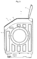
- Fig. 3 is a left side view showing an appearance of the drum type washing/drying machine according to the present invention.
- Fig. 4A is a partly exploded top view showing the structure of a water supply channel in the drum type washing/drying machine according to the present invention.
- Fig. 4B is a top view showing a detergent container of the drum type washing/drying machine according to the present invention.
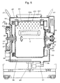
- Fig. 5 is a front longitudinal sectional view showing the main part of an inside structure of the drum type washing/drying machine according to the present invention.
- Fig. 6 is a front longitudinal sectional view showing a drying air stream in the drum type washing/drying machine according to the present invention.
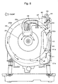
- Fig. 7 is a left side view showing the main part of the drum type washing/drying machine according to the present invention.
- Fig. 8 is a right side view showing the main part of the drum type washing/drying machine according to the present invention.
- Fig. 9 is a top cross-sectional view showing the drying air stream in the drum type washing/drying machine according to the present invention.
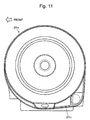
- Fig. 10 is a longitudinal sectional view showing the body of an outer tub in the drum type washing/drying machine according to the present invention.
- Fig. 11 is a right side view showing a side face of the body of the outer tub of Fig. 10.
- Fig. 12 is a side sectional view showing main parts around a throw-in opening in the drum type washing/drying machine according to the present invention.
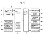
- Fig. 13 is a block diagram showing an electrical system of the drum type washing/drying machine according to the present invention.
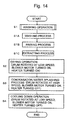
- Fig. 14 is a flowchart showing an example of operation of the drum type washing/drying machine according to the present invention.
- a housing 1 forming an external shape of the drum type washing/drying machine includes a slating face 1c between the top face 1a and the front face 1b.
- the corner between the top face 1a and the slanting face 1c, and the corner between the slanting face 1c and the front race 1b are slightly rounded.
- a throw-in opening 3 is formed on the slanting face 1c and the top face 1a.
- a lid 2 is provided for the throw-in opening 3 with a horizontal hinge 4 at the rear part of the throw-in opening 3.
- the lid 2 is foldable upward. With the structure, when a user pulls up and pushes forward the lid 2 with a handhold 2a, the lid 2 is folded as shown by the reference numeral 2' in Fig. 3 and stands at the rear of the throw-in opening 3.
- a detergent container 5 which is withdrawable frontward is provided to the left of the lid 2, and an operation panel 6 extending in the front-back direction is provided to the right of the lid 2 as shown in Figs. 4A and 4B.
- Various operation keys for setting washing courses, start time and so forth as well as various displays including a display which is lit responsive to the settings, a display for showing the progress (percentage of completion) in a washing course, a display for displaying the start time or a time remaining until the completion of the washing course and so forth are properly disposed on the operation panel 6. Since most part of the operation panel 6 is facing upward, its surface is almost perpendicular to the visual line of the user when the user stands in front of the washing machine and looks at the operation panel 6. Thus the displays are easy to view and the operation keys are easy to press.
- a water inlet 7 for connecting to an external water hose and a bath water inlet 8 for connecting to a bath water hose are provided at the rear part of the lid 2 on the top face 1a of the housing 1.
- a bath water pump 10 is disposed directly under the bath water inlet 8, and a water supply valve 9 is disposed directly under the water inlet 7.
- the detergent container 5 has the shape of a box whose top face as a whole is omitted, and an inside thereof is divided into a powdery detergent containing section 5a, a liquid detergent containing section 5b and a fabric softener containing section 5C.
- the water supply valve 9 is a quadruple valve, and is capable of selectively performing: water supply via the powdery detergent containing section 5a and the fabric softener containing section 5b; water supply via the softener containing section 5c for the final rinsing; water supply for balance adjustment in a centrifugal extraction which will be described later; or water supply to a water pipe for water-cooling a humid air containing water vapor discharged from laundry in a drying operation which will also be described later.
- Figs. 5-12 are appropriately simplified for the convenience of following explanations.
- a drum with a substantially cylindrical peripheral wall is rotated about an axis extending horizontally or slightly inclined upward in the front-back direction.
- the drum type washing/drying machine is provided with a drum 23 rotated about an axis extending horizontally in the lateral direction.
- an outer tub 20 with a substantially cylindrical peripheral wall and substantially closed ends is retained inside the housing 1 by way of a pair of springs 21 and a damper 22.
- the springs 21 suspend and support the outer tub 20 from the right and left sides of the housing 1, and the damper 22 supports the lower part of the outer tub in the front-back direction, so that the outer tub 20 is allowed a certain degree of oscillation.
- the drum 23 with a substantially cylindrical peripheral wall and substantially closed ends is provided inside the outer tub 20 rotatably about a horizontal axis C extending laterally.
- the drum 23 is provided with many through holes 23a for passing water.
- the main shaft 24 fixed to the center of the left side of the drum 23 is supported by a first bearing 26, which is retained by a first bearing case 27 fixed to the left side of the outer tub 20.
- An auxiliary shaft 25 fixed to the center of the right side of the drum 23 is supported by a second bearing 28, which is retained by a second bearing case 29 fixed to the right side of the outer tub 20.
- the main shaft 24 and the auxiliary shaft 25 define the horizontal axis C. Oil seals are provided between the main shaft 24 and the first bearing cases 27, and between the auxiliary shaft 25 and the second bearing cases 29, respectively, so that water does not reach the first and second bearings 26 and 28 when water is stored in the outer tub 20.
- the motor 30 of the present embodiment is an outer rotor type direct current brushless motor, whose rotor 30b is provided at an end of the main shaft 24 projecting laterally from the left side of the outer tub 20.
- the stator 30a of the motor 30 is fixed to the first bearing case 27, which also functions as a motor base.
- the rotor 30b which includes permanent magnets, is disposed in such a fashion as to surround the outer periphery of the stator 30a, which includes winding wires. Owing to the structure, the motor 30 is adequately thin in the direction of the horizontal axis C.
- the motor 30 Since the motor 30 is directly connected to the drum 23 with the main shaft 24 as described above, when a driving current is supplied to the stator 30a from the control circuit (not shown), the rotor 30b is rotated, and thereby the drum 23 is rotated via the main shaft 24 with the same speed.
- An air channel for circulating and supplying heated air to the outer tub 20 in the drying operation is disposed between the outer tub 20 and the housing 1 (not shown in Figs. 5 and 7) around the second bearing case 29 on the opposite side of the motor 30 across the drum 23.
- the channel will be described in more detail later.
- a drain 36 is provided at the lowermost part of the outer tub 20.
- the drain 36 leads to an external gutter via a drain valve 37 through a drain hose (not shown).
- a drain valve 37 When the drain valve 37 is opened, water retained in the outer tub 20 is evacuated from the machine through the drain 36 and the drain hose.
- a heater 38 extending substantially horizontally is disposed under the outer tub 20 to heat the water retained in the outer tub 20.
- the drum 23 Since the drum 23 is supported not by a cantilever manner but by both sides as described above, the drum 23 has less tendency to sway even if the laundry is huddled up in the drum by the extracting process.
- two balancers are used for steadily suppressing the swaying.
- One of them is a fluid balancer 32disposed on the left of the drum 23 where the motor 30 is also mounted.
- the fluid balancer 32 has a function substantially similar to that of a balancing ring used in conventional whirlpool type washing machines, which suppresses the swaying of the drum 23 by properly controlling the movement of fluid in a circular hollow body.
- a plurality of water storage tanks 33 are radially attached to the circumference of the right side of the drum 23, opposite to the fluid balancer across the drum 23.
- the water storage tanks 33 constitute a variable weight type balance adjustment mechanism together with a nozzle 34 for ejecting water to the openings, a water supply channel for supplying water from the water supply valve 9 to the nozzle 34 and so forth. More specifically, when the drum 23 is at a predetermined rotating position, water is ejected from the nozzle 34 to a water storage tank 33 in front of the nozzle 34. The water is held in the water storage tank 33 by the centrifugal force, and its weight functions as an eccentric load of the drum 23.
- the upper part of the periphery of the outer tub 20 lies just under the lid 2 of the throw-in opening 3, and the drum 23 is placed inside the outer tub 20.
- An outer tub opening 200 on the periphery of the outer tub 20 and a drum opening 230 on the periphery of the drum 23 are positioned slightly frontward from the upright direction.
- An outer tub door 201 is disposed for closing the outer tub opening 200.
- the outer tub door 201 is composed of a panel which opens rearward as being rotated about a shaft 202 extending substantially in parallel with the horizontal axis C.
- the drum door 231 for closing the drum opening 230 is composed of a pair of panels 232 and 233.
- the door panels 232 and 233 are respectively hinged to the periphery of the drum at opposite ends with respective shafts 234 and 235 which are substantially parallel with the horizontal axis C.
- the door panels 232 and 233 open frontward and rearward respectively.
- the opening operation is simplified by a door opening/closing mechanism 203 of the outer tub door 201. Owing to the door opening/closing mechanism 203, the outer tub door 201 and the drum door 231 can simultaneously be opened/closed simply by opening/closing the outer tub door 201 and performing a lock/unlock operation of the outer tub door 201.
- a drum position fixing unit 35 is disposed on the left side of the outer tub 20, so that the stop position hinges on a meshing of an engagement projection which projects from the unit 35 and an engagement recess formed on the rotor 30b of the motor 30.
- the body 20a of the outer tub is formed by an integral molding of synthetic resin, where the left side thereof is substantially closed and the right side thereof is opened, as shown in Figs. 10 and 11.
- the body 20a has an opening 20b under the substantially center of the horizontal axis C for communication with the inside of the outer tub 20 and a tubular pipeline 20c which is integrated therewith and extends along the horizontal axis C to the right side.
- the opening 20b serves as an air outlet for the outer tub 20, and the pipeline 20c serves as a part of the air channel.
- an end member 20d for substantially closing the right side is attached to the right opening side of the body 20a of the outer tub 20.
- a circular opening 20e is provided on a part of the outer tub 20 corresponding to the pipeline 20c, and a heat exchanger cover 40 is attached to the opening 20e.
- a rear vertical ventilation passage 41 serves as a part of the air channel and extends substantially vertically along the right side of the outer tub 20.
- a water pipe (not shown) connected with the water supply valve 9 leads to a water pipe connecting hole 42a disposed above the heat exchanger cover 40, and the rear vertical ventilation passage 41 functions substantially as a heat exchanger 42 owing to water supplied thereto from the water pipe.
- the rear vertical ventilation passage 41 is narrowed by a projection 41a and, therefore, water supplied from the water pipe spouts out to enhance the cooling effect (i.e. heat exchanging effect) as well as to prevent contaminants such as lint from coming up along with an ascending air stream.
- the rear vertical ventilation passage 41 is connected with a rear horizontal ventilation passage 43 which extends slightly upward at an upper rear part of the outer tub 20, and the rear horizontal ventilation passage 43 is connected with a rear part of a blower chamber 44 in which a blower 45 is installed.
- the blower 45 is directly connected with a motor shaft of a blower motor 46.
- a horizontal ventilation passage 47 extending substantially horizontally and bending frontward at the outside of the outer tub 20 and then downward is connected to the right side of the blower chamber 44.
- the horizontal ventilation passage 47 is provided in such a fashion that an end thereof overlaps with the opening 29a of the second bearing case 29.
- a heater 48 composed of a seethed wiring is provided in the horizontal ventilation passage 47, so that the passage 47 serves substantially as a heater for heating air.
- a plurality of openings 20f are provided on a portion of the outer tub 20 inside the second bearing case 29, and the openings 20f serve as hot air inlets.
- the horizontal ventilation passage 47 needs to be highly heat resistant in view of the high temperature inside the passage 47, metal is used as the material for forming the passage 47. Since the temperature of the air passing through the rear vertical ventilation passage 41 and the rear horizontal ventilation passage 43 is lower than that passing through the passage 47, the rear vertical ventilation passage 41 and the rear horizontal ventilation passage 43 are made of synthetic resin. Among parts constituting the blower chamber 44, those disposed at the side of the motor 46 are made of metal and those disposed at the side of the rear horizontal ventilation 43 are made of synthetic resin. Metal is used because the parts exposed to the motor 46 requires to be rigid, in addition to heat resistant, in order to sustain the heavy motor 46.
- the blower 45 when the blower 45 is driven to rotate by the blower motor 46, the blower 45 inhales air from its rear and exhales the air to lateral sides thereof. Accordingly, an air stream advancing from the blower chamber 44 to the horizontal ventilation passage 47 is formed, and the air heated as passing through the horizontal ventilation passage 47 is blown into the outer tub 20 through the openings 20f serving as the hot air inlets of the outer tub 20.
- a plurality of openings 23b are provided on one side of the drum 23 at around the auxiliary shaft 25, and the heated air passes mainly through the openings 23b to flow into the drum 23. If wet laundry is loaded in the drum 23, the heated air passes through gaps among the laundry articles and among fibers to deprive the laundry of moisture.
- Air containing the moisture passes mainly through the water passing holes 23a, exits the drum 23 and then advances toward the air outlet 20b through the gap between the drum 23 and the outer tub 20.
- Such flow of air around the drum 23 is promoted by the rotation of the drum 23. Since the high temperature air flow in the drum 23 surrounds the drum 23, the temperature inside the drum 23 becomes adequately high so that a high drying efficiency is achieved.
- the water generated by the condensation in the heat exchanger 42 slides down along the inner wall of the heat exchanger cover 40 and is discharged from a discharge outlet (not shown). In addition, the discharge outlet is formed in a gap between the body 20a and the end member 20d.
- the drying air channel is arranged mainly at the outside and the right side of the outer tub 20. More specifically, since the motor 30 is provided at the left side of the outer tub 20 and the air channel is provided at the right side of the outer tub 20, the lateral balance of the outer tub 20 is well achieved. Accordingly, suspension by the springs 21 is easily performed without problem while swaying in the extracting process is suppressed. Further, since the space around the second bearing case 29 is adequately utilized for arranging the air channel, the space between the outer tub 20 and the housing 1 is effectively used.
- the blower 45 and the blower motor 46 are disposed in the rear of the body of the outer tub 20 in such a fashion that its axis B is horizontal and substantially perpendicular to the horizontal axis C, the space between the body of the outer tub 20 and the housing 1 is also effectively used.
- the space between the outer tub 20 and the housing 1 effectively as described above it is possible to downsize the housing 1 while enlarging the outer tub 20, whereby ultimately the washing capacity is increased.
- the detergent container is disposed just above the first bearing case 27 and the motor 30 in the drum type washing/drying machine of the present invention. Accordingly, the space inside the housing 1 corresponding to the thickness of the motor 30 can be used effectively.
- the operation panel 6 is disposed just above the horizontal ventilation passage 47 which is a part of the air channel on the right of the outer tub 20, the space in the housing 1 corresponding to the operation panel 6 can also be used effectively.
- the wall of the horizontal ventilation passage 47 on which the heater 48 is installed becomes particularly hot.
- the water pipe 42b extending from the water supply valve 9 to the heat exchanger 42 is designed to pass under the operation panel 6. Accordingly, since cooling water passes through the water pipe 42b during the drying operation, the water pipe 42b functions as a thermal insulator to shield the heat from the wall of the horizontal ventilation passage 47 lying underneath, thereby preventing the operation panel from being abnormally heated.
- FIG. 13 is a block diagram showing the electrical system of the washing/drying machine.
- a controller 50 uses a microcomputer including a CPU, ROM, RAM, timer and so forth and performs various control operations such as operation of processes relating to washing/drying as described later based on a control program stored in the ROM.
- the controller is connected to: an operation unit 61 which is used by a user when determining the settings and giving instructions; a display 62 with which the user can confirm the settings and operation state; a water level sensor 52 for detecting the level of water stored in the outer tub 20; temperature sensors 53 for detecting temperatures of the water and air; a door switch 54 for detecting whether the lid 2 is opened or closed; and so forth.
- a load driving unit 51 is also connected to the controller 50, and the drum motor 30, the blower motor 46, the heater for lukewarm water 38, the drying heater 48, the water supply valve 9, the drain valve 37 and so forth are controlled by way of the load driving unit 51.
- the user opens the lid 2 and then opens the outer tub door 201 and the drum door 231 to throw laundry into the drum 23.
- the user fills the detergent container with a detergent and a fabric softener, and then operates the operation panel 6 to input instructions for a washing/drying operation.
- the controller 50 starts a washing operation responsive to the instructions (Step S1).
- bath water or water supplied from the external supply tap is poured into the outer tub 20 via the detergent container 5.
- the drain valve 37 is closed, and the washing water dissolving the detergent contained in the detergent container 5 is stored in the outer tub 20.
- the water stored in the outer tub 20 flows into the drum 23 through the through holes 23a, etc., whereby the laundry is soaked in the water.
- a driving current is supplied to the stator 30a of the motor 30 to rotate the drum 23 in a predetermined rotational direction at a predetermined speed.
- the laundry is tumbled inside the drum 23 (Step S1A).
- Step S1B After the washing process is finished, a rinsing process is performed in the similar manner (Step S1B), followed by an extracting process (Step S1C).
- the rotational speed of the motor 30 is raised to about 1,000 rpm to rotate the drum 23 at the same speed, whereby a centrifugal extraction is achieved.
- the fluid balancer 32 in addition to the balance adjustment mechanism including the water storage tanks 33 when necessary, works to prevent the drum 23, the outer tub 20, and the housing 1 from oscillating violently. It is possible to perform a moderate extraction after the washing process or after a rinsing process except the final one.
- Step S2 the drying operation
- the blower motor 46 is first tuned on, and the drying heater 48 is turned on after a certain period, 5 seconds for example, from the actuation of the blower motor 46. Since the controller 50 detects the start of rotation of the blower motor 46 during the period, it is assured that the heating is started only after the blower motor 46 is actuated and the air stream is generated in the air channel.
- the drying heater 48 is turned on, heated air produced by the heater 48 is blown into the drum 23 as described above. Also, the drum 23 is rotated at a slow speed similar to that employed in the washing process, so that the laundry is adequately agitated to be equally exposed to the heated air. Humid air containing moisture evaporated from the wet laundry is cooled and the water vapor is condensed to water in the heat exchanger 42 so that the air is dried and heated again by the heater 48.
- the temperature sensors 53 are provided in the vicinity of the opening 20b which is the air outlet from the outer tub 20 and in the vicinity of a sealing portion of a joint of the pipeline 20c and the heat exchanger cover, respectively. Since water stagnated near the discharge rests in the vicinity of the joint and the latter temperature sensor is almost always submerged in water during the drying operation in actual use, the latter temperature sensor detects the temperature of the water.
- the controller 50 judges the degree of drying of the laundry based on a difference between the temperatures detected by the temperature sensors 53 and terminates the drying operation when the temperature difference exceeds a predetermined value.
- a condensed water splashing process is performed (Step S3).
- the high temperature air containing a large amount of water vapor passes through the gap between the outer tub 20 and the drum 23 in the above described drying operation.
- the inner wall of the outer tub 20 is heated by the air, while the temperature of the air outside the outer tub 20 is the same as or lower than and close to the room temperature. Therefore, the outer tub 20 itself acts like a heat exchanger, and the condensed water is deposited on the inner wall of the outer tub 20. If such condensed water is deposited on the underside of the outer tub door 201, the water may drop on the drum 23 and moisten the laundry which has been dried.
- the condensed water splashing operation is performed to prevent such an undesired moistening of the laundry, wherein the drum 23 is rotated at a high rotational speed of about 600 to 800 rpm.
- Step S4 A cooling down process is performed (Step S4) after the condensed water splashing process has been performed for a predetermined period (e.g., 1 to 3 minutes).
- the cooling down process is performed for the purpose of reducing a temperature of the laundry, wherein cooled air, which is prepared by the use of cooling water prepared in the heat exchanger by driving the blower motor 46 without performing the heating by the heater 48, is circulated inside the drum 23.
- the blower motor 46 and the drum motor 30 are tuned off to finish the washing/drying operation.
- the user is informed of the completion by an appropriate display or buzzer. The user then opens the lid 2 to open the doors of the outer tub 20 and the drum 23 and takes out the laundry from the drum 23.
- the condensed water is perfectly eliminated when the user takes the laundry out of the drum 23 even if the condensed water has deposited on the outer tub door 201 and/or the inner wall of the outer tub 20 at the time when the drying operation is finished. Therefore, the dried laundry will not be moistened by the dripping of the condensed water.
Abstract
Description
- The present invention relates to a drum type washing and drying machine having a drum rotated about a horizontal or inclined axis.
- A drum type washing/drying machine has an outer tub and a cylindrical basket type drum which is disposed in the outer tub and rotates about a horizontal or inclined axis. The drum is rotated in the outer tub containing water with laundry loaded therein to wash the laundry by tumbling them. After the washing, the wet laundry is dried by heated air blown into the outer tub.
- One of the major dissatisfactions among consumers of the above drum type washing/drying machine is the difficulty in loading or unloading clothes. More specifically, a conventional and widespread drum type washing machine has a substantially rectangular parallelpiped housing provided with a front door which opens laterally for a user to load clothes in. When the door is opened, a throw-in opening provided on the front end of the drum can be seen through an opening provided in the outer tub. Accordingly, the throw-in opening is typically located at a lower part of the washing/drying machine and, therefore, the difficulty in loading or unloading clothes cannot be completely eliminated even by placing the washing/drying machine on a dedicated platform. In order to resolve the dissatisfaction, in some of the currently available drum type washing/drying machines, a throw-in opening of a drum is directed slightly upward by the use of an inclined axis. Also, in some washing/drying machines, a throw-in opening is designed to be as large as possible. These structures, however, cannot yield a satisfactory result for those who are accustomed to user-friendly whirl type washing machines.
- Further, in one of washing methods often carried out by the consumers, laundry is firstly soaked in a solution of bleach or the like stored in a bucket or the like, and then the laundry with the solution or only the laundry is transferred to the washing tub of the washing/drying machine. With the above-mentioned conventional drum type washing/drying machines, the laundry often drips the solution onto floor when only the laundry is transferred from the bucket to the washing tub (drum) and, also, it is very difficult to transfer the solution itself from the bucket to the washing tub. Such difficulties are also considered as shortcomings of the drum type washing/drying machine.
- Owing to the above arrangements of the drum type washing/drying machine, the height of the housing could be decreased, but the width and the length tend to increase. Particularly, since it is necessary to place the washing/drying machine on a waterproofing pan in collective housings such as an apartment, the housing is under a rigid size limitation. In turn, there has been a demand for a larger washing capacity in recent years, and it is necessary to design such a washing/drying machine which has a housing reduced in size and an outer tub increased in capacity. Therefore, the space between the housing and the outer tub is inevitably narrowed, and it is necessary to arrange components in the space more effectively. In the drum type washing/drying machine, particularly, it is necessary to dispose not only components required for rotating the drum (e.g., the driving unit for the drum), but also components required for drying (e.g., an air channel for drying), which is considerably difficult.
- In the drum type washing/drying machine, a circulating air channel is formed to be used in a drying operation: for blowing heated air into the outer tub; for discharging humid air containing water evaporated from the wet laundry out of the outer tub; for drying the humid air by passing it through a water-cooling (or air-cooling) heat exchanger which condenses water vapor into water; and for heating the dry air again to supply the heated air into the outer tub. In the drying operation, the outer tub itself acts like a heat exchanger because the temperature inside the outer tub is raised due to the heated air while the temperature of the air outside the outer tub is relatively low, and the water vapor is sometimes condensed to form water droplets inside the outer tub. The water droplets remaining inside the outer tub after a completion of the drying operation drip on the laundry due to vibration of the outer tub which occurs when a user takes out the laundry, thereby moistening the dried laundry in some cases.
- The present invention is accomplished in view of the above-mentioned problems, and an object thereof is to provide a drum type washing/drying machine which is user-friendly and has a washing capacity as large as possible by effectively using the space between the housing and the outer tub without increasing the size of the housing.
- Another object of the present invention is to provide a drum type washing/drying machine capable of preventing dried laundry from being moistened by water condensed on an inner wall of the outer tub during a drying operation.
- In accordance with a first aspect of the present invention, a drum type washing/drying machine includes:
- a housing;
- an outer tub having a body with a substantially cylindrical peripheral wall enclosed in the housing;
- a drum with a substantially cylindrical peripheral wall mounted rotatably about a horizontal or inclined axis in the outer tub;
- a throw-in opening formed on the peripheral wall of the drum;
- an opening formed on the top of the housing, the opening of the housing leading to the throw-in opening;
- a lid for the opening of the housing;
- a main shaft fixed to one side of the drum;
- a direct drive type motor connected directly to the main shaft and disposed at one side of the outer tub opposite to said one side of the drum to which the main shaft is fixed; and
- a hot air inlet for supplying heated air for drying to the outer tub and a main part of an air channel leading to the hot air inlet both provided at the other side of the outer tub.
-
- In the drum type washing/drying machine according to the first aspect, it is possible to throw laundry in the drum from a substantially upright or obliquely upward direction because the throw-in opening is provided on the top of the housing. Therefore, it is unnecessary for a user to bend when loading or unloading the laundry in the drum as is the case with a conventional drum type washing/drying machine, and the user can easily load or unload the laundry without changing her/his standing posture. Also, laundry, which has been soaked into a liquid in a bucket in advance of washing, can be transferred from the bucket to the drum together with the liquid. Thus, the drum type washing/drying machine according to the first aspect is user-friendly as a whirlpool type washing machine.
- Since the motor is provided at one side of the outer tub and the main part of the drying air channel is provided at the other side of the outer tub, it is possible to effectively use the space between the housing and the outer tub while keeping a good balance. As a result, it is possible to suppress the size of the housing and while enlarging the outer tub (particularly, its diameter), thereby increasing the washing capacity. Further, since the air channel and the motor are provided at opposite sides of the outer tub across the drum, the balance of weight of the outer tub becomes so good that a suspension of the outer tub is easily achieved. Furthermore, owing to the good weight balance of the outer tub, oscillation in an extracting process is effectively suppressed.
- Since the direct drive method is employed for the rotational driving of the drum, noise is reduced because a belt such as a belt drive is eliminated. The direct drive method is advantageous in terms of electric power saving because the method is free from power losses otherwise caused by a slippage of the belt and so forth. In addition, with the above-described structure, an outer rotor type motor may be used for making the dimension of the housing along the axis as small as possible.
- In the drum type washing/drying machine according to the first aspect, an air outlet which extends from the outer tub to lead to the air channel may be provided at the lower part of the body of the outer tub and at about the center in the axial direction of the body.
- With the above-described structure, the heated air, which is supplied to the outer tub through the hot air inlet disposed at one side of the outer tub, flows into the drum and then passes through gaps among the laundry articles and fibers of the laundry to exit from the drum through holes provided on the body of the drum. After that, the heated air flows mainly along the gap in the peripheral direction between the drum and the outer tub to reach the air outlet, whereby the heated air exits from the outer tub. Thus, since the drum is completely surrounded by the heated air, a temperature in the drum becomes uniformly high to improve the drying efficiency. Therefore, the time required for the drying operation is shortened and nonuniform drying is avoided.
- In accordance with a second aspect of the present invention, a drum type washing/drying machine includes:
- a housing;
- an outer tub having a body with a substantially cylindrical peripheral wall enclosed in the housing;
- a drum with a substantially cylindrical peripheral wall mounted rotatably about a horizontal or inclined axis in the outer tub;
- a main shaft fixed to one side of the drum;
- a driving unit provided at one side of the outer tub for rotatably driving the main shaft;
- a hot air inlet for supplying heated air for drying to the outer tub and a main part of an air channel leading to the hot air inlet both provided at the other side of the outer tub; and
- an air outlet leading to the air channel and provided at the lower part of the body of the outer tub and at about the center in the axial direction of the body.
-
- Since the driving unit is provided at one side of the outer tub while the main part of the drying air channel is provided at the other side of the outer tub in the drum type washing/drying machine according to the second aspect, too, it is possible to effectively use the space between the housing and the outer tub. Accordingly, it is possible to maintain the size of the housing while enlarging the outer tub (particularly, its diameter), thereby increasing the washing capacity. Also, since the drum is completely surrounded by the heated air in the drying operation as described above, the temperature in the drum becomes uniformly high to improve the drying efficiency. Thus, the time required for the drying operation is shortened and nonuniform drying is avoided. Further, since no air channel is disposed at the upper part of the outer tub, it is possible to provide the throw-in opening on a top of the outer tub. According to the above-described structure, the user can load and unload the laundry easily with keeping her/his standing posture because the user can throw the laundry in the drum from the upright or obliquely upward direction.
- In addition, in the drum type washing/drying machine according to the second aspect, the driving unit may be the direct drive type motor which is used also in the drum type washing/drying machine according to the first aspect or may be a belt drive type driving mechanism.
- In the drum type washing/drying machine according to the first and second aspects, a part of the air channel, which extends from the air outlet provided on the body of the outer tub along the axial direction of the body, may be formed integrally with the outer tub.
- For example, in the case where the outer tub is molded out of synthetic resin, the part of the air channel may be integrally molded with the outer tub. In this case, it is possible to reduce the manufacturing and assembling costs as compared with the case of assembling them as separate components.
- In addition, in the drum type washing/drying machine according to the first and second aspects, the main part of the air channel may include a heater for heating the air and a heat exchanger to be used for dehumidifying the air evacuated from the outer tub by cooling. Either one of an air-cooling heat exchanger or a water-cooling heat exchanger may be used as the heat exchanger; however, it is preferable to use the water-cooling heat exchanger for achieving a high degree of cooling effect with a small space.
- In the drum type washing/drying machine according to the first and second aspects, at least one of a detergent container and an operation panel may be disposed above the main part of the air channel. Owing to this structure, a space having the thickness of the drying air channel can be used effectively as a space for the detergent container or a space for an electrical circuit including switches and a display of the operation panel.
- It should be noted that, since the heated and high-temperature air passes through the air channel, the electrical circuit of the operation panel is brought to a high temperature by the heat discharged from the air channel and it may fail. The detergent container, which is typically made of synthetic resin, may be deformed if it becomes hot due to the heat. Therefore, it is preferable to provide a thermal insulator between the main part of the air channel and the detergent container or the operation panel disposed above the main part.
- A typical example of the material used as the thermal insulator is glass wool. Another example is a water pipe which passes cooling water. It functions as a heat exchanger which dehumidify the air discharged during the drying operation from the outer tub by cooling it. When a part of the water pipe is disposed between the main part of the air channel and the detergent container or the operation panel, it also functions as the thermal insulator. According to the above-described structure, it is possible to surely prevent failures of the electrical components of the operation panel or the deformation of the detergent container because the heat discharged from the air channel is absorbed by the water pipe, and is prevented from being conducted to the detergent container or the operation panel.
- According to a third aspect of the present invention, a drum type washing/drying machine includes:
- a housing;
- an outer tub having a body with a substantially cylindrical peripheral wall enclosed in the housing;
- a drum with a substantially cylindrical peripheral wall mounted rotatably about a horizontal or inclined axis in the outer tub;
- a throw-in opening formed on the peripheral wall of the drum;
- an opening formed on a top of the housing, the opening of the housing leading to the throw-in opening;
- a lid for the opening of the housing; and
- a blower motor for blowing heated air into the outer tub in a drying operation, the blower motor provided outside the body of the outer tub in such a fashion that the shaft of blower motor being substantially perpendicular to the axis of the drum.
-
- According to the above structure, the width of the body of the outer tub can be increased by the size of the blower motor since the blower motor is not disposed outside the outer tub. Accordingly, it is possible to widen the throw-in opening in the axial direction of the drum, thereby making it easier to load and unload the laundry in and from the drum.
- Further, in the drum type washing/drying machine according to the third aspect, at least the upper part of the body of the outer tub may have a substantially cylindrical shape, and the blower motor may be disposed at any region near the body of the outer tub except around the top of the body.
- With the above-described structure, it is possible to dispose the blower motor adequately in the space between the housing and the outer tub, which is advantageous for increasing the diameter of the outer tub while maintaining the size of the housing.
- According to a fourth aspect of the present invention, a drum type washing/drying machine includes:
- a housing;
- an outer tub having a body with a substantially cylindrical peripheral wall enclosed in the housing;
- a drum with a substantially cylindrical peripheral wall mounted rotatably about a horizontal or inclined axis in the outer tub;
- an operation controller for increasing the rotational speed of the drum to an increased speed which moves water deposited on the inner wall of the outer tub after a predetermined drying operation is finished and for maintaining the increased speed for a predetermined period of time.
-
- In the drum type washing/drying machine according to the fourth aspect, the rotational speed of the drum for agitating the laundry during the drying operation is almost the same as that employed in the washing process, and the rotational speed is increased when the drying operation is finished. The increased rotational speed generates an air stream which flows through the space between the drum and the outer tub at such a high speed that moves the water droplets formed on the inner wall of the outer tub. Thus, if the water is condensed during the drying operation on the inner wall of the outer tub, the high-speed air stream splashes the water or moves the water along the inner wall of the outer tub to ultimately evacuate the water from the outer tub. Therefore, no water remains on the inner wall of the outer tub when all the processes are finished, and it is possible to securely prevent the laundry from being moistened by dripping of the water deposited on the inner wall of the outer tub which may otherwise occur when the user takes the laundry out of the drum. The rotational speed for moving the water deposited on the inner wall of the outer tub may be almost the same as that employed in an extracting process, but the rotational speed may preferably be lower than that in view of the oscillation and noise. For example, if the highest rotational speed in the extracting process is 1,000 rpm, a rotational speed of 600 to 800 rpm achieves a satisfactory effect.
- The moistening of the laundry by the dripping of water, which occurs when the user takes the laundry out of the drum, is particularly prominent when the throw-in opening is provided on the top of the drum. Therefore, the drum type washing/drying machine according to the fourth aspect, particularly, is suitably used as a drum type washing/drying machine having a structure wherein the throw-in opening is formed on the peripheral wall of the drum, and the opening leading to the throw-in opening and the lid for the opening of the housing are provided on the top of the housing.
- Fig. 1 is a front view showing an appearance of an embodiment of a drum type washing/drying machine according to the present invention.
- Fig. 2 is a top view showing an appearance of the drum type washing/drying machine according to the present invention.
- Fig. 3 is a left side view showing an appearance of the drum type washing/drying machine according to the present invention.
- Fig. 4A is a partly exploded top view showing the structure of a water supply channel in the drum type washing/drying machine according to the present invention.
- Fig. 4B is a top view showing a detergent container of the drum type washing/drying machine according to the present invention.
- Fig. 5 is a front longitudinal sectional view showing the main part of an inside structure of the drum type washing/drying machine according to the present invention.
- Fig. 6 is a front longitudinal sectional view showing a drying air stream in the drum type washing/drying machine according to the present invention.
- Fig. 7 is a left side view showing the main part of the drum type washing/drying machine according to the present invention.
- Fig. 8 is a right side view showing the main part of the drum type washing/drying machine according to the present invention.
- Fig. 9 is a top cross-sectional view showing the drying air stream in the drum type washing/drying machine according to the present invention.
- Fig. 10 is a longitudinal sectional view showing the body of an outer tub in the drum type washing/drying machine according to the present invention.
- Fig. 11 is a right side view showing a side face of the body of the outer tub of Fig. 10.
- Fig. 12 is a side sectional view showing main parts around a throw-in opening in the drum type washing/drying machine according to the present invention.
- Fig. 13 is a block diagram showing an electrical system of the drum type washing/drying machine according to the present invention.
- Fig. 14 is a flowchart showing an example of operation of the drum type washing/drying machine according to the present invention.
- A drum type washing machine according to the first to fourth aspects of the present invention will be described with reference to the accompanying drawings. As shown in Figs. 1 to 3, a
housing 1 forming an external shape of the drum type washing/drying machine includes a slatingface 1c between the top face 1a and thefront face 1b. The corner between the top face 1a and the slantingface 1c, and the corner between the slantingface 1c and thefront race 1b are slightly rounded. A throw-inopening 3 is formed on the slantingface 1c and the top face 1a. Alid 2 is provided for the throw-inopening 3 with ahorizontal hinge 4 at the rear part of the throw-inopening 3. Thelid 2 is foldable upward. With the structure, when a user pulls up and pushes forward thelid 2 with ahandhold 2a, thelid 2 is folded as shown by the reference numeral 2' in Fig. 3 and stands at the rear of the throw-inopening 3. - A
detergent container 5 which is withdrawable frontward is provided to the left of thelid 2, and anoperation panel 6 extending in the front-back direction is provided to the right of thelid 2 as shown in Figs. 4A and 4B. Various operation keys for setting washing courses, start time and so forth as well as various displays including a display which is lit responsive to the settings, a display for showing the progress (percentage of completion) in a washing course, a display for displaying the start time or a time remaining until the completion of the washing course and so forth are properly disposed on theoperation panel 6. Since most part of theoperation panel 6 is facing upward, its surface is almost perpendicular to the visual line of the user when the user stands in front of the washing machine and looks at theoperation panel 6. Thus the displays are easy to view and the operation keys are easy to press. - As shown in Figs. 2 and 4A, a
water inlet 7 for connecting to an external water hose and abath water inlet 8 for connecting to a bath water hose are provided at the rear part of thelid 2 on the top face 1a of thehousing 1. Abath water pump 10 is disposed directly under thebath water inlet 8, and awater supply valve 9 is disposed directly under thewater inlet 7. As shown in Fig. 4B, thedetergent container 5 has the shape of a box whose top face as a whole is omitted, and an inside thereof is divided into a powderydetergent containing section 5a, a liquiddetergent containing section 5b and a fabric softener containing section 5C. - The
water supply valve 9 is a quadruple valve, and is capable of selectively performing: water supply via the powderydetergent containing section 5a and the fabricsoftener containing section 5b; water supply via thesoftener containing section 5c for the final rinsing; water supply for balance adjustment in a centrifugal extraction which will be described later; or water supply to a water pipe for water-cooling a humid air containing water vapor discharged from laundry in a drying operation which will also be described later. - Figs. 5-12 are appropriately simplified for the convenience of following explanations. In a conventional drum type washing/drying machine, a drum with a substantially cylindrical peripheral wall is rotated about an axis extending horizontally or slightly inclined upward in the front-back direction. In the present invention, the drum type washing/drying machine is provided with a
drum 23 rotated about an axis extending horizontally in the lateral direction. - More specifically, as shown in Figs. 5 and 7, an
outer tub 20 with a substantially cylindrical peripheral wall and substantially closed ends is retained inside thehousing 1 by way of a pair ofsprings 21 and adamper 22. Thesprings 21 suspend and support theouter tub 20 from the right and left sides of thehousing 1, and thedamper 22 supports the lower part of the outer tub in the front-back direction, so that theouter tub 20 is allowed a certain degree of oscillation. Thedrum 23 with a substantially cylindrical peripheral wall and substantially closed ends is provided inside theouter tub 20 rotatably about a horizontal axis C extending laterally. Thedrum 23 is provided with many through holes 23a for passing water. - The
main shaft 24 fixed to the center of the left side of thedrum 23 is supported by afirst bearing 26, which is retained by afirst bearing case 27 fixed to the left side of theouter tub 20. Anauxiliary shaft 25 fixed to the center of the right side of thedrum 23 is supported by asecond bearing 28, which is retained by asecond bearing case 29 fixed to the right side of theouter tub 20. Themain shaft 24 and theauxiliary shaft 25 define the horizontal axis C. Oil seals are provided between themain shaft 24 and thefirst bearing cases 27, and between theauxiliary shaft 25 and thesecond bearing cases 29, respectively, so that water does not reach the first andsecond bearings outer tub 20. - The
motor 30 of the present embodiment is an outer rotor type direct current brushless motor, whoserotor 30b is provided at an end of themain shaft 24 projecting laterally from the left side of theouter tub 20. In turn, thestator 30a of themotor 30 is fixed to thefirst bearing case 27, which also functions as a motor base. Therotor 30b, which includes permanent magnets, is disposed in such a fashion as to surround the outer periphery of thestator 30a, which includes winding wires. Owing to the structure, themotor 30 is adequately thin in the direction of the horizontal axis C. Since themotor 30 is directly connected to thedrum 23 with themain shaft 24 as described above, when a driving current is supplied to thestator 30a from the control circuit (not shown), therotor 30b is rotated, and thereby thedrum 23 is rotated via themain shaft 24 with the same speed. - An air channel for circulating and supplying heated air to the
outer tub 20 in the drying operation is disposed between theouter tub 20 and the housing 1 (not shown in Figs. 5 and 7) around thesecond bearing case 29 on the opposite side of themotor 30 across thedrum 23. The channel will be described in more detail later. - A
drain 36 is provided at the lowermost part of theouter tub 20. Thedrain 36 leads to an external gutter via adrain valve 37 through a drain hose (not shown). Thus, when thedrain valve 37 is opened, water retained in theouter tub 20 is evacuated from the machine through thedrain 36 and the drain hose. Also, aheater 38 extending substantially horizontally is disposed under theouter tub 20 to heat the water retained in theouter tub 20. - Since the
drum 23 is supported not by a cantilever manner but by both sides as described above, thedrum 23 has less tendency to sway even if the laundry is huddled up in the drum by the extracting process. However, two balancers are used for steadily suppressing the swaying. One of them is a fluid balancer 32disposed on the left of thedrum 23 where themotor 30 is also mounted. Thefluid balancer 32 has a function substantially similar to that of a balancing ring used in conventional whirlpool type washing machines, which suppresses the swaying of thedrum 23 by properly controlling the movement of fluid in a circular hollow body. - In turn, a plurality of
water storage tanks 33, each in the form of a pocket opened to the inside of thedrum 23, are radially attached to the circumference of the right side of thedrum 23, opposite to the fluid balancer across thedrum 23. Thewater storage tanks 33 constitute a variable weight type balance adjustment mechanism together with anozzle 34 for ejecting water to the openings, a water supply channel for supplying water from thewater supply valve 9 to thenozzle 34 and so forth. More specifically, when thedrum 23 is at a predetermined rotating position, water is ejected from thenozzle 34 to awater storage tank 33 in front of thenozzle 34. The water is held in thewater storage tank 33 by the centrifugal force, and its weight functions as an eccentric load of thedrum 23. Thus, it is possible to alleviate the eccentricity of thewhole drum 23 by appropriately ejecting water to the water storage tank positioned opposite to the eccentric load generated by the laundry huddled in thedrum 23 across the horizontal axis C. As for the balance adjustment method and specific structure thereof, those proposed by the present applicant in Japanese Patent Application No. 2001-161855 can be employed in the present invention. - As shown in Fig. 12, the upper part of the periphery of the
outer tub 20 lies just under thelid 2 of the throw-inopening 3, and thedrum 23 is placed inside theouter tub 20. An outer tub opening 200 on the periphery of theouter tub 20 and adrum opening 230 on the periphery of thedrum 23 are positioned slightly frontward from the upright direction. Anouter tub door 201 is disposed for closing theouter tub opening 200. Theouter tub door 201 is composed of a panel which opens rearward as being rotated about ashaft 202 extending substantially in parallel with the horizontal axis C. In turn, thedrum door 231 for closing thedrum opening 230 is composed of a pair ofpanels door panels respective shafts door panels lid 2 to load laundry in thedrum 23, theouter tub door 201 and thedrum door 231 need to be opened too. In the present washing machine, the opening operation is simplified by a door opening/closing mechanism 203 of theouter tub door 201. Owing to the door opening/closing mechanism 203, theouter tub door 201 and thedrum door 231 can simultaneously be opened/closed simply by opening/closing theouter tub door 201 and performing a lock/unlock operation of theouter tub door 201. - Since the
drum 23 is rotated inside theouter tub 20, it is necessary that the position of thedrum opening 230 coincides with the position of theouter tub opening 200 when thedrum 23 is stopped. Therefore, a drumposition fixing unit 35 is disposed on the left side of theouter tub 20, so that the stop position hinges on a meshing of an engagement projection which projects from theunit 35 and an engagement recess formed on therotor 30b of themotor 30. - The structure of the drying air channel will hereinafter be described in detail with reference to Figs. 6 and 8-11. The
body 20a of the outer tub is formed by an integral molding of synthetic resin, where the left side thereof is substantially closed and the right side thereof is opened, as shown in Figs. 10 and 11. Thebody 20a has anopening 20b under the substantially center of the horizontal axis C for communication with the inside of theouter tub 20 and atubular pipeline 20c which is integrated therewith and extends along the horizontal axis C to the right side. Theopening 20b serves as an air outlet for theouter tub 20, and thepipeline 20c serves as a part of the air channel. - As shown in Figs. 6 and 8, an
end member 20d for substantially closing the right side is attached to the right opening side of thebody 20a of theouter tub 20. Acircular opening 20e is provided on a part of theouter tub 20 corresponding to thepipeline 20c, and aheat exchanger cover 40 is attached to theopening 20e. Inside theheat exchanger cover 40, a rearvertical ventilation passage 41 serves as a part of the air channel and extends substantially vertically along the right side of theouter tub 20. A water pipe (not shown) connected with thewater supply valve 9 leads to a waterpipe connecting hole 42a disposed above theheat exchanger cover 40, and the rearvertical ventilation passage 41 functions substantially as aheat exchanger 42 owing to water supplied thereto from the water pipe. - The rear
vertical ventilation passage 41 is narrowed by aprojection 41a and, therefore, water supplied from the water pipe spouts out to enhance the cooling effect (i.e. heat exchanging effect) as well as to prevent contaminants such as lint from coming up along with an ascending air stream. - As shown in Figs. 6, 8 and 9, the rear
vertical ventilation passage 41 is connected with a rearhorizontal ventilation passage 43 which extends slightly upward at an upper rear part of theouter tub 20, and the rearhorizontal ventilation passage 43 is connected with a rear part of ablower chamber 44 in which ablower 45 is installed. Theblower 45 is directly connected with a motor shaft of ablower motor 46. Ahorizontal ventilation passage 47 extending substantially horizontally and bending frontward at the outside of theouter tub 20 and then downward is connected to the right side of theblower chamber 44. Thehorizontal ventilation passage 47 is provided in such a fashion that an end thereof overlaps with theopening 29a of thesecond bearing case 29. Aheater 48 composed of a seethed wiring is provided in thehorizontal ventilation passage 47, so that thepassage 47 serves substantially as a heater for heating air. A plurality of openings 20f are provided on a portion of theouter tub 20 inside thesecond bearing case 29, and the openings 20f serve as hot air inlets. - Since the
horizontal ventilation passage 47 needs to be highly heat resistant in view of the high temperature inside thepassage 47, metal is used as the material for forming thepassage 47. Since the temperature of the air passing through the rearvertical ventilation passage 41 and the rearhorizontal ventilation passage 43 is lower than that passing through thepassage 47, the rearvertical ventilation passage 41 and the rearhorizontal ventilation passage 43 are made of synthetic resin. Among parts constituting theblower chamber 44, those disposed at the side of themotor 46 are made of metal and those disposed at the side of the rearhorizontal ventilation 43 are made of synthetic resin. Metal is used because the parts exposed to themotor 46 requires to be rigid, in addition to heat resistant, in order to sustain theheavy motor 46. - In the above-described structure, when the
blower 45 is driven to rotate by theblower motor 46, theblower 45 inhales air from its rear and exhales the air to lateral sides thereof. Accordingly, an air stream advancing from theblower chamber 44 to thehorizontal ventilation passage 47 is formed, and the air heated as passing through thehorizontal ventilation passage 47 is blown into theouter tub 20 through the openings 20f serving as the hot air inlets of theouter tub 20. A plurality ofopenings 23b are provided on one side of thedrum 23 at around theauxiliary shaft 25, and the heated air passes mainly through theopenings 23b to flow into thedrum 23. If wet laundry is loaded in thedrum 23, the heated air passes through gaps among the laundry articles and among fibers to deprive the laundry of moisture. Air containing the moisture passes mainly through the water passing holes 23a, exits thedrum 23 and then advances toward theair outlet 20b through the gap between thedrum 23 and theouter tub 20. Such flow of air around thedrum 23 is promoted by the rotation of thedrum 23. Since the high temperature air flow in thedrum 23 surrounds thedrum 23, the temperature inside thedrum 23 becomes adequately high so that a high drying efficiency is achieved. - The air containing a large amount of water vapor, which has been evacuated from the
outer tub 20 via theair outlet 20b, is subjected to a rapid cooling when it reaches theheat exchanger 42 through thepipeline 20c and the rearhorizontal ventilation passage 41, whereby the water vapor contained in the air is condensed to water. Therefore, the air that has passed through theheat exchanger 42 becomes dry and returns to theblower chamber 44 after passing through the rearhorizontal ventilation passage 43, so that the dry air is circulated to be heated again by theheater 48. The water generated by the condensation in theheat exchanger 42 slides down along the inner wall of theheat exchanger cover 40 and is discharged from a discharge outlet (not shown). In addition, the discharge outlet is formed in a gap between thebody 20a and theend member 20d. - As described above, the drying air channel is arranged mainly at the outside and the right side of the
outer tub 20. More specifically, since themotor 30 is provided at the left side of theouter tub 20 and the air channel is provided at the right side of theouter tub 20, the lateral balance of theouter tub 20 is well achieved. Accordingly, suspension by thesprings 21 is easily performed without problem while swaying in the extracting process is suppressed. Further, since the space around thesecond bearing case 29 is adequately utilized for arranging the air channel, the space between theouter tub 20 and thehousing 1 is effectively used. Moreover, since theblower 45 and theblower motor 46 are disposed in the rear of the body of theouter tub 20 in such a fashion that its axis B is horizontal and substantially perpendicular to the horizontal axis C, the space between the body of theouter tub 20 and thehousing 1 is also effectively used. By using the space between theouter tub 20 and thehousing 1 effectively as described above, it is possible to downsize thehousing 1 while enlarging theouter tub 20, whereby ultimately the washing capacity is increased. - As can be seen from Figs. 1 to 5, the detergent container is disposed just above the
first bearing case 27 and themotor 30 in the drum type washing/drying machine of the present invention. Accordingly, the space inside thehousing 1 corresponding to the thickness of themotor 30 can be used effectively. In turn, since theoperation panel 6 is disposed just above thehorizontal ventilation passage 47 which is a part of the air channel on the right of theouter tub 20, the space in thehousing 1 corresponding to theoperation panel 6 can also be used effectively. - In the drying operation, the wall of the
horizontal ventilation passage 47 on which theheater 48 is installed becomes particularly hot. In order to prevent the heat discharged from the wall from affecting theoperation panel 6 disposed just above thehorizontal ventilation passage 47, thewater pipe 42b extending from thewater supply valve 9 to theheat exchanger 42 is designed to pass under theoperation panel 6. Accordingly, since cooling water passes through thewater pipe 42b during the drying operation, thewater pipe 42b functions as a thermal insulator to shield the heat from the wall of thehorizontal ventilation passage 47 lying underneath, thereby preventing the operation panel from being abnormally heated. - Configuration of the electrical system and a characteristic operation of the washing/drying machine of the present invention will hereinafter be described. Fig. 13 is a block diagram showing the electrical system of the washing/drying machine. A
controller 50 uses a microcomputer including a CPU, ROM, RAM, timer and so forth and performs various control operations such as operation of processes relating to washing/drying as described later based on a control program stored in the ROM. The controller is connected to: anoperation unit 61 which is used by a user when determining the settings and giving instructions; adisplay 62 with which the user can confirm the settings and operation state; awater level sensor 52 for detecting the level of water stored in theouter tub 20;temperature sensors 53 for detecting temperatures of the water and air; adoor switch 54 for detecting whether thelid 2 is opened or closed; and so forth. Aload driving unit 51 is also connected to thecontroller 50, and thedrum motor 30, theblower motor 46, the heater forlukewarm water 38, the dryingheater 48, thewater supply valve 9, thedrain valve 37 and so forth are controlled by way of theload driving unit 51. - An example of the operation of the washing/drying machine will hereinafter be described with reference to a flowchart of Fig. 14. The following operation is a standard automatic operation, wherein process steps from the start to the end of a washing/drying operation are continuously performed.
- The user opens the
lid 2 and then opens theouter tub door 201 and thedrum door 231 to throw laundry into thedrum 23. The user fills the detergent container with a detergent and a fabric softener, and then operates theoperation panel 6 to input instructions for a washing/drying operation. Thecontroller 50 starts a washing operation responsive to the instructions (Step S1). In the washing operation, bath water or water supplied from the external supply tap is poured into theouter tub 20 via thedetergent container 5. At this point, thedrain valve 37 is closed, and the washing water dissolving the detergent contained in thedetergent container 5 is stored in theouter tub 20. The water stored in theouter tub 20 flows into thedrum 23 through the through holes 23a, etc., whereby the laundry is soaked in the water. To start a washing process, a driving current is supplied to thestator 30a of themotor 30 to rotate thedrum 23 in a predetermined rotational direction at a predetermined speed. Thus, the laundry is tumbled inside the drum 23 (Step S1A). - After the washing process is finished, a rinsing process is performed in the similar manner (Step S1B), followed by an extracting process (Step S1C). In the extracting process, the rotational speed of the
motor 30 is raised to about 1,000 rpm to rotate thedrum 23 at the same speed, whereby a centrifugal extraction is achieved. In the centrifugal extraction, thefluid balancer 32, in addition to the balance adjustment mechanism including thewater storage tanks 33 when necessary, works to prevent thedrum 23, theouter tub 20, and thehousing 1 from oscillating violently. It is possible to perform a moderate extraction after the washing process or after a rinsing process except the final one. - When the washing operation is finished, the operation proceeds to a drying operation (Step S2). In the drying operation, the
blower motor 46 is first tuned on, and the dryingheater 48 is turned on after a certain period, 5 seconds for example, from the actuation of theblower motor 46. Since thecontroller 50 detects the start of rotation of theblower motor 46 during the period, it is assured that the heating is started only after theblower motor 46 is actuated and the air stream is generated in the air channel. When the dryingheater 48 is turned on, heated air produced by theheater 48 is blown into thedrum 23 as described above. Also, thedrum 23 is rotated at a slow speed similar to that employed in the washing process, so that the laundry is adequately agitated to be equally exposed to the heated air. Humid air containing moisture evaporated from the wet laundry is cooled and the water vapor is condensed to water in theheat exchanger 42 so that the air is dried and heated again by theheater 48. - The
temperature sensors 53 are provided in the vicinity of theopening 20b which is the air outlet from theouter tub 20 and in the vicinity of a sealing portion of a joint of thepipeline 20c and the heat exchanger cover, respectively. Since water stagnated near the discharge rests in the vicinity of the joint and the latter temperature sensor is almost always submerged in water during the drying operation in actual use, the latter temperature sensor detects the temperature of the water. Thecontroller 50 judges the degree of drying of the laundry based on a difference between the temperatures detected by thetemperature sensors 53 and terminates the drying operation when the temperature difference exceeds a predetermined value. - After the drying operation, a condensed water splashing process is performed (Step S3). The high temperature air containing a large amount of water vapor passes through the gap between the
outer tub 20 and thedrum 23 in the above described drying operation. The inner wall of theouter tub 20 is heated by the air, while the temperature of the air outside theouter tub 20 is the same as or lower than and close to the room temperature. Therefore, theouter tub 20 itself acts like a heat exchanger, and the condensed water is deposited on the inner wall of theouter tub 20. If such condensed water is deposited on the underside of theouter tub door 201, the water may drop on thedrum 23 and moisten the laundry which has been dried. This may happen due to a vibration caused by the user when the user opens the door after the washing/drying operation is finished. The condensed water splashing operation is performed to prevent such an undesired moistening of the laundry, wherein thedrum 23 is rotated at a high rotational speed of about 600 to 800 rpm. - A remarkably high-speed air stream occurs in the gap between the
drum 23 and theouter tub 20 when the drum is rotated at the high speed. Therefore, the condensed water deposited on the inner wall of theouter tub 20 is caught up in the air stream and becomes fine water droplets to be drained off or the condensed water is moved along the inner wall of theouter tub 20 by the air stream to be a large condensation and drained off. A cooling down process is performed (Step S4) after the condensed water splashing process has been performed for a predetermined period (e.g., 1 to 3 minutes). The cooling down process is performed for the purpose of reducing a temperature of the laundry, wherein cooled air, which is prepared by the use of cooling water prepared in the heat exchanger by driving theblower motor 46 without performing the heating by theheater 48, is circulated inside thedrum 23. - After completion of the cooling down process of a predetermined period, the
blower motor 46 and thedrum motor 30 are tuned off to finish the washing/drying operation. When all the processes are finished, the user is informed of the completion by an appropriate display or buzzer. The user then opens thelid 2 to open the doors of theouter tub 20 and thedrum 23 and takes out the laundry from thedrum 23. - As described above, the condensed water is perfectly eliminated when the user takes the laundry out of the
drum 23 even if the condensed water has deposited on theouter tub door 201 and/or the inner wall of theouter tub 20 at the time when the drying operation is finished. Therefore, the dried laundry will not be moistened by the dripping of the condensed water. - While this invention has been described in conjunction with a preferred embodiment thereof, it is apparent that many modifications and variations will be made without departing from the scope of the appended claims.
Claims (11)
- A drum type washing/drying machine comprising:a housing;an outer tub having a body with a substantially cylindrical peripheral wall enclosed in the housing;a drum with a substantially cylindrical peripheral wall mounted rotatably about a horizontal or inclined axis in the outer tub;a throw-in opening formed on the peripheral wall of the drum;an opening formed on a top of the housing, the opening of the housing leading to the throw-in opening;a lid for the opening of the housing;a main shaft fixed to one side of the drum;a direct drive type motor connected directly to the main shaft and disposed at one side of the outer tub opposite to said one side of the drum to which the main shaft is fixed; anda hot air inlet for supplying heated air for drying to the outer tub and a main part of an air channel leading to the hot air inlet both provided at the other side of the outer tub.
- The drum type washing/drying machine according to claim 1, wherein an air outlet leading to the air channel from the outer tub is provided at a portion which is on a lower part of the body of the outer tub and near the center along the axial direction of the body.
- A drum type washing/drying machine comprising:a housing;an outer tub having a body with a substantially cylindrical peripheral wall enclosed in the housing;a drum with a substantially cylindrical peripheral wall mounted rotatably about a horizontal or inclined axis in the outer tub;a main shaft fixed to one side of the drum;a driving unit provided at one side of the outer tub for rotatably driving the main shaft;a hot air inlet for supplying heated air for drying to the outer tub and a main part of an air channel leading to the hot air inlet both provided at the other side of the outer tub; andan air outlet leading to the air channel and provided at a portion on a lower part of the body of the outer tub and near the center along the axial direction of the body.
- The drum type washing/drying machine according to claim 1, wherein a channel, which is a part of the air channel, extending from the air outlet provided on the body of the outer tub in the axial direction of the body is formed integrally with the outer tub.
- The drum type washing/drying machine according to claim 1, wherein at least one of a detergent container and an operation panel is disposed above the main part of the air channel.
- The drum type washing/drying machine according to claim 5, wherein a thermal insulator is provided between the main part of the air channel and the detergent container and/or the operation panel disposed above the main part of the air channel.
- The drum type washing/drying machine according to claim 6, wherein the drum type washing/drying machine further comprises a water pipe for passing cooling water to be used as a heat exchanger for dehumidifying air exhausted from the outer tub by cooling in the drying operation, a part of the water pipe disposed between the main part of the air channel and the detergent container and/or the operation panel as the thermal insulator.
- A drum type washing/drying machine comprising:a housing;an outer tub having a body with a substantially cylindrical peripheral wall enclosed in the housing;a drum with a substantially cylindrical peripheral wall mounted rotatably about a horizontal or inclined axis in the outer tub;a throw-in opening formed on the peripheral wall of the drum;an opening formed on a top of the housing, the opening of the housing leading to the throw-in opening;a lid for the opening of the housing; anda blower motor for blowing heated air into the outer tub during a drying operation, the blower motor provided outside a body of the outer tub in such a fashion that a shaft of the blower motor is substantially perpendicular to an extending direction of the axis of the drum.
- The drum type washing/drying machine according to claim 8, wherein at least an upper part of the body of the outer tub has a substantially cylindrical shape, and the blower motor is disposed at any region adjacent to the body of the outer tub but regions around a top of the body.
- A drum type washing/drying machine comprising:a housing;an outer tub having a body with a substantially cylindrical peripheral wall enclosed in the housing;a drum with a substantially cylindrical peripheral wall mounted rotatably about a horizontal or inclined axis in the outer tub; andan operation controller for increasing a rotational speed of the drum to reach a rotational speed which causes water deposited on an inner wall of the outer tub to move after a completion of a predetermined drying operation and maintaining the rotational speed for a predetermined period of time.
- The drum type washing/drying machine according to claim 10, wherein the throw-in opening is formed on the peripheral wall of the drum, and an opening leading to the throw-in opening as well as a lid for the opening of the housing are formed on a top of the housing.
Applications Claiming Priority (2)
| Application Number | Priority Date | Filing Date | Title |
|---|---|---|---|
| JP2001349197A JP3605067B2 (en) | 2001-11-14 | 2001-11-14 | Drum type washer / dryer |
| JP2001349197 | 2001-11-14 |
Publications (3)
| Publication Number | Publication Date |
|---|---|
| EP1314809A2 true EP1314809A2 (en) | 2003-05-28 |
| EP1314809A3 EP1314809A3 (en) | 2003-06-18 |
| EP1314809B1 EP1314809B1 (en) | 2006-05-10 |
Family
ID=19161903
Family Applications (1)
| Application Number | Title | Priority Date | Filing Date |
|---|---|---|---|
| EP02024845A Expired - Lifetime EP1314809B1 (en) | 2001-11-14 | 2002-11-08 | Drum type washing and drying machine |
Country Status (7)
| Country | Link |
|---|---|
| US (1) | US20030089138A1 (en) |
| EP (1) | EP1314809B1 (en) |
| JP (1) | JP3605067B2 (en) |
| KR (1) | KR100664628B1 (en) |
| CN (1) | CN1209520C (en) |
| AT (1) | ATE325913T1 (en) |
| DE (1) | DE60211282T2 (en) |
Cited By (5)
| Publication number | Priority date | Publication date | Assignee | Title |
|---|---|---|---|---|
| EP1657341A2 (en) * | 2004-11-12 | 2006-05-17 | LG Electronics Inc. | Method and apparatus for control of drying process in a washing and drying machine |
| EP2019160A1 (en) * | 2007-07-26 | 2009-01-28 | CANDY S.p.A. | Washer-drier machine |
| CN1773008B (en) * | 2004-11-12 | 2011-02-16 | Lg电子株式会社 | Method for control of drying process in a washing and drying machine |
| EP3040463A1 (en) * | 2015-01-05 | 2016-07-06 | LG Electronics Inc. | Washing machine |
| WO2018097493A1 (en) | 2016-11-24 | 2018-05-31 | Samsung Electronics Co., Ltd. | Washing machine |
Families Citing this family (49)
| Publication number | Priority date | Publication date | Assignee | Title |
|---|---|---|---|---|
| US8844160B2 (en) | 1997-04-29 | 2014-09-30 | Whirlpool Corporation | Modular fabric revitalizing system |
| US20070151312A1 (en) * | 2005-12-30 | 2007-07-05 | Bruce Beihoff C | Modular fabric revitalizing system |
| JP3609789B2 (en) * | 2002-03-06 | 2005-01-12 | 三洋電機株式会社 | Drum washing machine |
| JP4093951B2 (en) * | 2003-11-25 | 2008-06-04 | 松下電器産業株式会社 | Drum type washer / dryer |
| JP2005152476A (en) * | 2003-11-27 | 2005-06-16 | Sanyo Electric Co Ltd | Drum type washing and drying machine |
| KR101033584B1 (en) * | 2004-04-19 | 2011-05-11 | 엘지전자 주식회사 | heatproof plate fastening structure for drum type washing machine with laundry drying function |
| KR101033585B1 (en) * | 2004-04-20 | 2011-05-11 | 엘지전자 주식회사 | drum type washing machine |
| US20050241345A1 (en) * | 2004-05-03 | 2005-11-03 | Daewoo Electronics Corporation | Washing machine equipped with a radiation drying unit |
| JP4030523B2 (en) * | 2004-05-12 | 2008-01-09 | 三洋電機株式会社 | Washing machine |
| JP2006026407A (en) | 2004-07-20 | 2006-02-02 | Samsung Electronics Co Ltd | Drum washing machine |
| DE102005003694A1 (en) * | 2005-01-26 | 2006-07-27 | BSH Bosch und Siemens Hausgeräte GmbH | A method for impregnating weatherproof clothing in a domestic horizontal drum washing machine has an additional process following the normal wash process in which a special reproofing material is added, heated and soaked for a period |
| DE102005013052A1 (en) * | 2005-03-18 | 2006-09-21 | BSH Bosch und Siemens Hausgeräte GmbH | Clothes drying machine |
| DE102006002713A1 (en) * | 2005-03-18 | 2006-10-12 | BSH Bosch und Siemens Hausgeräte GmbH | Front assembly for a laundry drying machine |
| DE102005013051A1 (en) * | 2005-03-18 | 2006-09-21 | BSH Bosch und Siemens Hausgeräte GmbH | Condensation Dryer |
| ES2279675B1 (en) * | 2005-03-23 | 2008-08-01 | Ibai, S. Coop. | CLOTHING AND DRYING CLOTHING CLOTHING. |
| US8015726B2 (en) * | 2005-06-23 | 2011-09-13 | Whirlpool Corporation | Automatic clothes dryer |
| KR100925908B1 (en) * | 2005-07-28 | 2009-11-09 | 샤프 가부시키가이샤 | Drum type drying and washing machine |
| US7921578B2 (en) * | 2005-12-30 | 2011-04-12 | Whirlpool Corporation | Nebulizer system for a fabric treatment appliance |
| US7665227B2 (en) | 2005-12-30 | 2010-02-23 | Whirlpool Corporation | Fabric revitalizing method using low absorbency pads |
| US7735345B2 (en) | 2005-12-30 | 2010-06-15 | Whirlpool Corporation | Automatic fabric treatment appliance with a manual fabric treatment station |
| JP4022239B1 (en) * | 2006-08-10 | 2007-12-12 | シャープ株式会社 | Washing dryer and control method thereof |
| CA2599353C (en) * | 2006-09-06 | 2011-05-24 | Lg Electronics Inc. | Dryer with clogging detecting function |
| CA2599375C (en) * | 2006-09-06 | 2011-06-21 | Lg Electronics Inc. | Clogging detecting system for dryer |
| US20080110044A1 (en) * | 2006-11-14 | 2008-05-15 | Robertshaw Controls Company | Dryer Configured for Fresh Air Induction |
| US20080113609A1 (en) * | 2006-11-14 | 2008-05-15 | Robertshaw Controls Company | Combined Supply and Exhaust Apparatus |
| KR100860053B1 (en) * | 2007-04-06 | 2008-09-24 | 주식회사 대우일렉트로닉스 | Drum type washing machine |
| DE112007003563B4 (en) * | 2007-07-10 | 2017-08-17 | Lg Electronics Inc. | Washing method for releasing a roughened surface of a washed fabric |
| JP5072022B2 (en) * | 2007-10-01 | 2012-11-14 | 株式会社東京洗染機械製作所 | Compartmental dryer |
| KR20120088034A (en) * | 2010-10-19 | 2012-08-08 | 엘지전자 주식회사 | laundry machine having a drying function |
| ES2694665T3 (en) * | 2013-12-03 | 2018-12-26 | Arçelik Anonim Sirketi | Dryer with heat pump |
| KR101672079B1 (en) * | 2013-12-20 | 2016-11-02 | 동부대우전자 주식회사 | Drum tyme washing machine |
| CN104727112B (en) * | 2013-12-24 | 2018-05-08 | 博西华电器(江苏)有限公司 | Clothes treatment device |
| KR20150074731A (en) | 2013-12-24 | 2015-07-02 | 동부대우전자 주식회사 | Washing machine |
| EP3224403B1 (en) * | 2014-11-26 | 2019-08-14 | JRF Technologies Limited | A clothes dryer |
| US10024597B2 (en) * | 2014-11-26 | 2018-07-17 | Extractor Corporation | Centrifugal separator |
| KR102493407B1 (en) * | 2016-01-04 | 2023-01-31 | 엘지전자 주식회사 | Laundry Treating Apparatus |
| KR20170095656A (en) * | 2016-02-15 | 2017-08-23 | 동부대우전자 주식회사 | Washing machine having protection against heat structure |
| KR102381040B1 (en) * | 2016-11-24 | 2022-03-31 | 삼성전자주식회사 | Washing machine |
| JP2018086229A (en) * | 2016-11-24 | 2018-06-07 | 三星電子株式会社Samsung Electronics Co.,Ltd. | Drum type washing machine |
| CN107558093B (en) * | 2017-08-10 | 2019-10-22 | 珠海格力电器股份有限公司 | Panel assembly, washing machine and the method for cooling |
| CN111850930B (en) * | 2019-04-08 | 2023-05-12 | 青岛海尔洗涤电器有限公司 | Washing machine with drying function |
| EP3741898B1 (en) * | 2019-05-21 | 2023-08-02 | BSH Hausgeräte GmbH | Device for washing and drying objects and method for operating such a device |
| CN211670752U (en) * | 2019-06-17 | 2020-10-13 | 菲舍尔和佩克尔应用有限公司 | Motor assembly, washing machine, clothes dryer and washing and drying machine |
| JP2023540755A (en) * | 2020-09-04 | 2023-09-26 | エルジー エレクトロニクス インコーポレイティド | Dryer |
| WO2022050768A1 (en) * | 2020-09-04 | 2022-03-10 | Lg Electronics Inc. | Laundry treating apparatus |
| AU2021336358A1 (en) * | 2020-09-04 | 2023-04-06 | Lg Electronics Inc. | Laundry treating apparatus |
| CN112160119A (en) * | 2020-09-15 | 2021-01-01 | 海信(山东)冰箱有限公司 | Control method of washing machine |
| US20220145507A1 (en) | 2020-11-06 | 2022-05-12 | Whirlpool Corporation | Method Of Heating The Clothes Load In A Tumbling Combination Washer/Dryer |
| CN112376204A (en) * | 2020-11-25 | 2021-02-19 | 珠海格力电器股份有限公司 | Washing and drying machine and control method of temperature of machine body of washing and drying machine |
Citations (6)
| Publication number | Priority date | Publication date | Assignee | Title |
|---|---|---|---|---|
| US4112590A (en) * | 1975-07-02 | 1978-09-12 | August Lepper, Maschinen- Und Apparatebau Gmbh | Combined drum washer and drying arrangement |
| DE3403622A1 (en) * | 1984-02-02 | 1985-08-14 | Bosch-Siemens Hausgeräte GmbH, 7000 Stuttgart | Automatically controlled washing machine |
| EP0421442A2 (en) * | 1989-10-05 | 1991-04-10 | Sanyo Electric Co., Ltd. | drum-type washing machine |
| EP0481442A2 (en) * | 1990-10-16 | 1992-04-22 | Sharp Kabushiki Kaisha | Tumbler type washing/drying machine |
| FR2701042A1 (en) * | 1993-01-29 | 1994-08-05 | Esswein Sa | Washer-drier with air injection into the basket |
| EP1055765A1 (en) * | 1999-05-19 | 2000-11-29 | Kabushiki Kaisha Toshiba | Drum type washing machine with aligning structure for rotor and stator of drive motor |
-
2001
- 2001-11-14 JP JP2001349197A patent/JP3605067B2/en not_active Expired - Lifetime
-
2002
- 2002-11-04 US US10/286,766 patent/US20030089138A1/en not_active Abandoned
- 2002-11-08 DE DE60211282T patent/DE60211282T2/en not_active Expired - Lifetime
- 2002-11-08 EP EP02024845A patent/EP1314809B1/en not_active Expired - Lifetime
- 2002-11-08 AT AT02024845T patent/ATE325913T1/en not_active IP Right Cessation
- 2002-11-13 KR KR1020020070215A patent/KR100664628B1/en not_active IP Right Cessation
- 2002-11-13 CN CNB021493901A patent/CN1209520C/en not_active Expired - Lifetime
Patent Citations (6)
| Publication number | Priority date | Publication date | Assignee | Title |
|---|---|---|---|---|
| US4112590A (en) * | 1975-07-02 | 1978-09-12 | August Lepper, Maschinen- Und Apparatebau Gmbh | Combined drum washer and drying arrangement |
| DE3403622A1 (en) * | 1984-02-02 | 1985-08-14 | Bosch-Siemens Hausgeräte GmbH, 7000 Stuttgart | Automatically controlled washing machine |
| EP0421442A2 (en) * | 1989-10-05 | 1991-04-10 | Sanyo Electric Co., Ltd. | drum-type washing machine |
| EP0481442A2 (en) * | 1990-10-16 | 1992-04-22 | Sharp Kabushiki Kaisha | Tumbler type washing/drying machine |
| FR2701042A1 (en) * | 1993-01-29 | 1994-08-05 | Esswein Sa | Washer-drier with air injection into the basket |
| EP1055765A1 (en) * | 1999-05-19 | 2000-11-29 | Kabushiki Kaisha Toshiba | Drum type washing machine with aligning structure for rotor and stator of drive motor |
Cited By (9)
| Publication number | Priority date | Publication date | Assignee | Title |
|---|---|---|---|---|
| EP1657341A2 (en) * | 2004-11-12 | 2006-05-17 | LG Electronics Inc. | Method and apparatus for control of drying process in a washing and drying machine |
| EP1657341A3 (en) * | 2004-11-12 | 2006-08-23 | LG Electronics Inc. | Method and apparatus for control of drying process in a washing and drying machine |
| CN1773008B (en) * | 2004-11-12 | 2011-02-16 | Lg电子株式会社 | Method for control of drying process in a washing and drying machine |
| EP2019160A1 (en) * | 2007-07-26 | 2009-01-28 | CANDY S.p.A. | Washer-drier machine |
| EP3040463A1 (en) * | 2015-01-05 | 2016-07-06 | LG Electronics Inc. | Washing machine |
| US9797084B2 (en) | 2015-01-05 | 2017-10-24 | Lg Electronics Inc. | Washing machine |
| WO2018097493A1 (en) | 2016-11-24 | 2018-05-31 | Samsung Electronics Co., Ltd. | Washing machine |
| EP3526388A4 (en) * | 2016-11-24 | 2019-09-04 | Samsung Electronics Co., Ltd. | Washing machine |
| US10538871B2 (en) | 2016-11-24 | 2020-01-21 | Samsung Electronics Co., Ltd. | Washing machine |
Also Published As
| Publication number | Publication date |
|---|---|
| ATE325913T1 (en) | 2006-06-15 |
| EP1314809A3 (en) | 2003-06-18 |
| JP3605067B2 (en) | 2004-12-22 |
| DE60211282D1 (en) | 2006-06-14 |
| EP1314809B1 (en) | 2006-05-10 |
| JP2003144789A (en) | 2003-05-20 |
| DE60211282T2 (en) | 2007-05-10 |
| US20030089138A1 (en) | 2003-05-15 |
| KR20030040116A (en) | 2003-05-22 |
| CN1419004A (en) | 2003-05-21 |
| KR100664628B1 (en) | 2007-01-04 |
| CN1209520C (en) | 2005-07-06 |
Similar Documents
| Publication | Publication Date | Title |
|---|---|---|
| EP1314809B1 (en) | Drum type washing and drying machine | |
| EP2290154B1 (en) | Drum type washing and drying machine | |
| JP5259441B2 (en) | Drum washing machine | |
| JP4391888B2 (en) | Monotab drum washing machine and washing control method thereof | |
| JP4163445B2 (en) | Washing and drying machine | |
| EP2447411A2 (en) | Drum-Type Washing Machine | |
| EP1544341B1 (en) | Washing machine with drying function | |
| JP2007222194A (en) | Washing/drying machine | |
| EP1369523B1 (en) | Laundry washer and dryer machine | |
| EP0501747A1 (en) | Washing and drying machine | |
| JP4286847B2 (en) | Washing and drying machine | |
| JP3773926B2 (en) | Drum type washer / dryer | |
| KR100416491B1 (en) | Combination washer-drier | |
| JP3806655B2 (en) | Drum type washer / dryer | |
| JP2022180071A (en) | washing machine | |
| JP2021142178A (en) | Washing and drying machine | |
| JP4948499B2 (en) | Washing and drying machine | |
| JP2014064723A (en) | Drum type washing and drying machine | |
| JP2018094112A (en) | Washing and drying machine | |
| JP2022159585A (en) | washing machine | |
| JP2002360990A (en) | Washing and drying machine | |
| JP2009028334A (en) | Washing machine | |
| JP2002360971A (en) | Washing and drying machine | |
| JP2002360967A (en) | Washing and drying machine | |
| JP2010119647A (en) | Washing/drying machine |
Legal Events
| Date | Code | Title | Description |
|---|---|---|---|
| PUAI | Public reference made under article 153(3) epc to a published international application that has entered the european phase |
Free format text: ORIGINAL CODE: 0009012 |
|
| PUAL | Search report despatched |
Free format text: ORIGINAL CODE: 0009013 |
|
| AK | Designated contracting states |
Designated state(s): AT BE BG CH CY CZ DE DK EE ES FI FR GB GR IE IT LI LU MC NL PT SE SK TR |
|
| AX | Request for extension of the european patent |
Extension state: AL LT LV MK RO SI |
|
| AK | Designated contracting states |
Designated state(s): AT BE BG CH CY CZ DE DK EE ES FI FR GB GR IE IT LI LU MC NL PT SE SK TR |
|
| AX | Request for extension of the european patent |
Extension state: AL LT LV MK RO SI |
|
| 17P | Request for examination filed |
Effective date: 20030719 |
|
| 17Q | First examination report despatched |
Effective date: 20031024 |
|
| AKX | Designation fees paid |
Designated state(s): DE IT |
|
| RBV | Designated contracting states (corrected) |
Designated state(s): AT BE BG CH CY CZ DE DK EE ES FI FR GB GR IE IT LI LU MC NL PT SE SK TR |
|
| GRAP | Despatch of communication of intention to grant a patent |
Free format text: ORIGINAL CODE: EPIDOSNIGR1 |
|
| GRAS | Grant fee paid |
Free format text: ORIGINAL CODE: EPIDOSNIGR3 |
|
| GRAA | (expected) grant |
Free format text: ORIGINAL CODE: 0009210 |
|
| AK | Designated contracting states |
Kind code of ref document: B1 Designated state(s): AT BE BG CH CY CZ DE DK EE ES FI FR GB GR IE IT LI LU MC NL PT SE SK TR |
|
| PG25 | Lapsed in a contracting state [announced via postgrant information from national office to epo] |
Ref country code: IT Free format text: LAPSE BECAUSE OF FAILURE TO SUBMIT A TRANSLATION OF THE DESCRIPTION OR TO PAY THE FEE WITHIN THE PRESCRIBED TIME-LIMIT;WARNING: LAPSES OF ITALIAN PATENTS WITH EFFECTIVE DATE BEFORE 2007 MAY HAVE OCCURRED AT ANY TIME BEFORE 2007. THE CORRECT EFFECTIVE DATE MAY BE DIFFERENT FROM THE ONE RECORDED. Effective date: 20060510 Ref country code: LI Free format text: LAPSE BECAUSE OF FAILURE TO SUBMIT A TRANSLATION OF THE DESCRIPTION OR TO PAY THE FEE WITHIN THE PRESCRIBED TIME-LIMIT Effective date: 20060510 Ref country code: FI Free format text: LAPSE BECAUSE OF FAILURE TO SUBMIT A TRANSLATION OF THE DESCRIPTION OR TO PAY THE FEE WITHIN THE PRESCRIBED TIME-LIMIT Effective date: 20060510 Ref country code: BE Free format text: LAPSE BECAUSE OF FAILURE TO SUBMIT A TRANSLATION OF THE DESCRIPTION OR TO PAY THE FEE WITHIN THE PRESCRIBED TIME-LIMIT Effective date: 20060510 Ref country code: AT Free format text: LAPSE BECAUSE OF FAILURE TO SUBMIT A TRANSLATION OF THE DESCRIPTION OR TO PAY THE FEE WITHIN THE PRESCRIBED TIME-LIMIT Effective date: 20060510 Ref country code: CH Free format text: LAPSE BECAUSE OF FAILURE TO SUBMIT A TRANSLATION OF THE DESCRIPTION OR TO PAY THE FEE WITHIN THE PRESCRIBED TIME-LIMIT Effective date: 20060510 Ref country code: NL Free format text: LAPSE BECAUSE OF FAILURE TO SUBMIT A TRANSLATION OF THE DESCRIPTION OR TO PAY THE FEE WITHIN THE PRESCRIBED TIME-LIMIT Effective date: 20060510 Ref country code: CZ Free format text: LAPSE BECAUSE OF FAILURE TO SUBMIT A TRANSLATION OF THE DESCRIPTION OR TO PAY THE FEE WITHIN THE PRESCRIBED TIME-LIMIT Effective date: 20060510 Ref country code: SK Free format text: LAPSE BECAUSE OF FAILURE TO SUBMIT A TRANSLATION OF THE DESCRIPTION OR TO PAY THE FEE WITHIN THE PRESCRIBED TIME-LIMIT Effective date: 20060510 |
|
| REG | Reference to a national code |
Ref country code: GB Ref legal event code: FG4D |
|
| REG | Reference to a national code |
Ref country code: CH Ref legal event code: EP |
|
| REF | Corresponds to: |
Ref document number: 60211282 Country of ref document: DE Date of ref document: 20060614 Kind code of ref document: P |
|
| REG | Reference to a national code |
Ref country code: IE Ref legal event code: FG4D |
|
| PG25 | Lapsed in a contracting state [announced via postgrant information from national office to epo] |
Ref country code: DK Free format text: LAPSE BECAUSE OF FAILURE TO SUBMIT A TRANSLATION OF THE DESCRIPTION OR TO PAY THE FEE WITHIN THE PRESCRIBED TIME-LIMIT Effective date: 20060810 Ref country code: SE Free format text: LAPSE BECAUSE OF FAILURE TO SUBMIT A TRANSLATION OF THE DESCRIPTION OR TO PAY THE FEE WITHIN THE PRESCRIBED TIME-LIMIT Effective date: 20060810 |
|
| PG25 | Lapsed in a contracting state [announced via postgrant information from national office to epo] |
Ref country code: ES Free format text: LAPSE BECAUSE OF FAILURE TO SUBMIT A TRANSLATION OF THE DESCRIPTION OR TO PAY THE FEE WITHIN THE PRESCRIBED TIME-LIMIT Effective date: 20060821 |
|
| PG25 | Lapsed in a contracting state [announced via postgrant information from national office to epo] |
Ref country code: PT Free format text: LAPSE BECAUSE OF FAILURE TO SUBMIT A TRANSLATION OF THE DESCRIPTION OR TO PAY THE FEE WITHIN THE PRESCRIBED TIME-LIMIT Effective date: 20061010 |
|
| NLV1 | Nl: lapsed or annulled due to failure to fulfill the requirements of art. 29p and 29m of the patents act | ||
| PG25 | Lapsed in a contracting state [announced via postgrant information from national office to epo] |
Ref country code: IE Free format text: LAPSE BECAUSE OF NON-PAYMENT OF DUE FEES Effective date: 20061108 |
|
| REG | Reference to a national code |
Ref country code: CH Ref legal event code: PL |
|
| ET | Fr: translation filed | ||
| PG25 | Lapsed in a contracting state [announced via postgrant information from national office to epo] |
Ref country code: MC Free format text: LAPSE BECAUSE OF NON-PAYMENT OF DUE FEES Effective date: 20061130 |
|
| PLBE | No opposition filed within time limit |
Free format text: ORIGINAL CODE: 0009261 |
|
| STAA | Information on the status of an ep patent application or granted ep patent |
Free format text: STATUS: NO OPPOSITION FILED WITHIN TIME LIMIT |
|
| 26N | No opposition filed |
Effective date: 20070213 |
|
| GBPC | Gb: european patent ceased through non-payment of renewal fee |
Effective date: 20061108 |
|
| PG25 | Lapsed in a contracting state [announced via postgrant information from national office to epo] |
Ref country code: GB Free format text: LAPSE BECAUSE OF NON-PAYMENT OF DUE FEES Effective date: 20061108 |
|
| PG25 | Lapsed in a contracting state [announced via postgrant information from national office to epo] |
Ref country code: GR Free format text: LAPSE BECAUSE OF FAILURE TO SUBMIT A TRANSLATION OF THE DESCRIPTION OR TO PAY THE FEE WITHIN THE PRESCRIBED TIME-LIMIT Effective date: 20060811 |
|
| PG25 | Lapsed in a contracting state [announced via postgrant information from national office to epo] |
Ref country code: BG Free format text: LAPSE BECAUSE OF FAILURE TO SUBMIT A TRANSLATION OF THE DESCRIPTION OR TO PAY THE FEE WITHIN THE PRESCRIBED TIME-LIMIT Effective date: 20060810 Ref country code: EE Free format text: LAPSE BECAUSE OF FAILURE TO SUBMIT A TRANSLATION OF THE DESCRIPTION OR TO PAY THE FEE WITHIN THE PRESCRIBED TIME-LIMIT Effective date: 20060510 |
|
| PG25 | Lapsed in a contracting state [announced via postgrant information from national office to epo] |
Ref country code: TR Free format text: LAPSE BECAUSE OF FAILURE TO SUBMIT A TRANSLATION OF THE DESCRIPTION OR TO PAY THE FEE WITHIN THE PRESCRIBED TIME-LIMIT Effective date: 20060510 Ref country code: LU Free format text: LAPSE BECAUSE OF NON-PAYMENT OF DUE FEES Effective date: 20061108 |
|
| PG25 | Lapsed in a contracting state [announced via postgrant information from national office to epo] |
Ref country code: CY Free format text: LAPSE BECAUSE OF FAILURE TO SUBMIT A TRANSLATION OF THE DESCRIPTION OR TO PAY THE FEE WITHIN THE PRESCRIBED TIME-LIMIT Effective date: 20060510 |
|
| PGFP | Annual fee paid to national office [announced via postgrant information from national office to epo] |
Ref country code: IT Payment date: 20101115 Year of fee payment: 9 |
|
| REG | Reference to a national code |
Ref country code: FR Ref legal event code: TQ Owner name: QINGDAO HAIER WASHING MACHINE CO., LTD., CN Effective date: 20130128 Ref country code: FR Ref legal event code: TQ Owner name: HAIER GROUP CORPORATION, CN Effective date: 20130128 |
|
| REG | Reference to a national code |
Ref country code: DE Ref legal event code: R081 Ref document number: 60211282 Country of ref document: DE Owner name: HAIER GROUP CORPORATION, CN Free format text: FORMER OWNER: SANYO ELECTRIC CO., LTD., MORIGUCHI-SHI, JP Effective date: 20130117 Ref country code: DE Ref legal event code: R081 Ref document number: 60211282 Country of ref document: DE Owner name: QINGDAO HAIER WASHING MACHINE CO. LTD., CN Free format text: FORMER OWNER: SANYO ELECTRIC CO., LTD., MORIGUCHI-SHI, JP Effective date: 20130117 Ref country code: DE Ref legal event code: R082 Ref document number: 60211282 Country of ref document: DE Representative=s name: HOEGER, STELLRECHT & PARTNER PATENTANWAELTE, DE Effective date: 20130117 Ref country code: DE Ref legal event code: R081 Ref document number: 60211282 Country of ref document: DE Owner name: HAIER GROUP CORPORATION, QINGDAO, CN Free format text: FORMER OWNER: SANYO ELECTRIC CO., LTD., MORIGUCHI-SHI, OSAKA, JP Effective date: 20130117 Ref country code: DE Ref legal event code: R081 Ref document number: 60211282 Country of ref document: DE Owner name: QINGDAO HAIER WASHING MACHINE CO. LTD., QINGDA, CN Free format text: FORMER OWNER: SANYO ELECTRIC CO., LTD., MORIGUCHI-SHI, OSAKA, JP Effective date: 20130117 Ref country code: DE Ref legal event code: R082 Ref document number: 60211282 Country of ref document: DE Representative=s name: HOEGER, STELLRECHT & PARTNER PATENTANWAELTE MB, DE Effective date: 20130117 |
|
| PG25 | Lapsed in a contracting state [announced via postgrant information from national office to epo] |
Ref country code: IT Free format text: LAPSE BECAUSE OF NON-PAYMENT OF DUE FEES Effective date: 20121108 |
|
| REG | Reference to a national code |
Ref country code: DE Ref legal event code: R082 Ref document number: 60211282 Country of ref document: DE Representative=s name: HOEGER, STELLRECHT & PARTNER PATENTANWAELTE MB, DE |
|
| REG | Reference to a national code |
Ref country code: FR Ref legal event code: PLFP Year of fee payment: 14 |
|
| REG | Reference to a national code |
Ref country code: FR Ref legal event code: PLFP Year of fee payment: 15 |
|
| PGFP | Annual fee paid to national office [announced via postgrant information from national office to epo] |
Ref country code: FR Payment date: 20161014 Year of fee payment: 15 |
|
| PGFP | Annual fee paid to national office [announced via postgrant information from national office to epo] |
Ref country code: DE Payment date: 20171031 Year of fee payment: 16 |
|
| REG | Reference to a national code |
Ref country code: FR Ref legal event code: ST Effective date: 20180731 |
|
| PG25 | Lapsed in a contracting state [announced via postgrant information from national office to epo] |
Ref country code: FR Free format text: LAPSE BECAUSE OF NON-PAYMENT OF DUE FEES Effective date: 20171130 |
|
| REG | Reference to a national code |
Ref country code: DE Ref legal event code: R119 Ref document number: 60211282 Country of ref document: DE |
|
| PG25 | Lapsed in a contracting state [announced via postgrant information from national office to epo] |
Ref country code: DE Free format text: LAPSE BECAUSE OF NON-PAYMENT OF DUE FEES Effective date: 20190601 |