EP1314409A2 - Liquefracture handpiece - Google Patents
Liquefracture handpiece Download PDFInfo
- Publication number
- EP1314409A2 EP1314409A2 EP03003909A EP03003909A EP1314409A2 EP 1314409 A2 EP1314409 A2 EP 1314409A2 EP 03003909 A EP03003909 A EP 03003909A EP 03003909 A EP03003909 A EP 03003909A EP 1314409 A2 EP1314409 A2 EP 1314409A2
- Authority
- EP
- European Patent Office
- Prior art keywords
- pumping chamber
- handpiece
- fluid
- electrodes
- newtons
- Prior art date
- Legal status (The legal status is an assumption and is not a legal conclusion. Google has not performed a legal analysis and makes no representation as to the accuracy of the status listed.)
- Ceased
Links
Images


Classifications
-
- A—HUMAN NECESSITIES
- A61—MEDICAL OR VETERINARY SCIENCE; HYGIENE
- A61F—FILTERS IMPLANTABLE INTO BLOOD VESSELS; PROSTHESES; DEVICES PROVIDING PATENCY TO, OR PREVENTING COLLAPSING OF, TUBULAR STRUCTURES OF THE BODY, e.g. STENTS; ORTHOPAEDIC, NURSING OR CONTRACEPTIVE DEVICES; FOMENTATION; TREATMENT OR PROTECTION OF EYES OR EARS; BANDAGES, DRESSINGS OR ABSORBENT PADS; FIRST-AID KITS
- A61F9/00—Methods or devices for treatment of the eyes; Devices for putting-in contact lenses; Devices to correct squinting; Apparatus to guide the blind; Protective devices for the eyes, carried on the body or in the hand
- A61F9/007—Methods or devices for eye surgery
- A61F9/00736—Instruments for removal of intra-ocular material or intra-ocular injection, e.g. cataract instruments
-
- A—HUMAN NECESSITIES
- A61—MEDICAL OR VETERINARY SCIENCE; HYGIENE
- A61B—DIAGNOSIS; SURGERY; IDENTIFICATION
- A61B17/00—Surgical instruments, devices or methods, e.g. tourniquets
- A61B17/32—Surgical cutting instruments
- A61B17/3203—Fluid jet cutting instruments
-
- A—HUMAN NECESSITIES
- A61—MEDICAL OR VETERINARY SCIENCE; HYGIENE
- A61B—DIAGNOSIS; SURGERY; IDENTIFICATION
- A61B17/00—Surgical instruments, devices or methods, e.g. tourniquets
- A61B17/32—Surgical cutting instruments
- A61B17/320068—Surgical cutting instruments using mechanical vibrations, e.g. ultrasonic
- A61B2017/320084—Irrigation sleeves
-
- A—HUMAN NECESSITIES
- A61—MEDICAL OR VETERINARY SCIENCE; HYGIENE
- A61B—DIAGNOSIS; SURGERY; IDENTIFICATION
- A61B18/00—Surgical instruments, devices or methods for transferring non-mechanical forms of energy to or from the body
- A61B18/04—Surgical instruments, devices or methods for transferring non-mechanical forms of energy to or from the body by heating
- A61B2018/044—Surgical instruments, devices or methods for transferring non-mechanical forms of energy to or from the body by heating the surgical action being effected by a circulating hot fluid
- A61B2018/046—Surgical instruments, devices or methods for transferring non-mechanical forms of energy to or from the body by heating the surgical action being effected by a circulating hot fluid in liquid form
-
- A—HUMAN NECESSITIES
- A61—MEDICAL OR VETERINARY SCIENCE; HYGIENE
- A61F—FILTERS IMPLANTABLE INTO BLOOD VESSELS; PROSTHESES; DEVICES PROVIDING PATENCY TO, OR PREVENTING COLLAPSING OF, TUBULAR STRUCTURES OF THE BODY, e.g. STENTS; ORTHOPAEDIC, NURSING OR CONTRACEPTIVE DEVICES; FOMENTATION; TREATMENT OR PROTECTION OF EYES OR EARS; BANDAGES, DRESSINGS OR ABSORBENT PADS; FIRST-AID KITS
- A61F9/00—Methods or devices for treatment of the eyes; Devices for putting-in contact lenses; Devices to correct squinting; Apparatus to guide the blind; Protective devices for the eyes, carried on the body or in the hand
- A61F9/007—Methods or devices for eye surgery
- A61F9/00736—Instruments for removal of intra-ocular material or intra-ocular injection, e.g. cataract instruments
- A61F9/00745—Instruments for removal of intra-ocular material or intra-ocular injection, e.g. cataract instruments using mechanical vibrations, e.g. ultrasonic
-
- A—HUMAN NECESSITIES
- A61—MEDICAL OR VETERINARY SCIENCE; HYGIENE
- A61F—FILTERS IMPLANTABLE INTO BLOOD VESSELS; PROSTHESES; DEVICES PROVIDING PATENCY TO, OR PREVENTING COLLAPSING OF, TUBULAR STRUCTURES OF THE BODY, e.g. STENTS; ORTHOPAEDIC, NURSING OR CONTRACEPTIVE DEVICES; FOMENTATION; TREATMENT OR PROTECTION OF EYES OR EARS; BANDAGES, DRESSINGS OR ABSORBENT PADS; FIRST-AID KITS
- A61F9/00—Methods or devices for treatment of the eyes; Devices for putting-in contact lenses; Devices to correct squinting; Apparatus to guide the blind; Protective devices for the eyes, carried on the body or in the hand
- A61F9/007—Methods or devices for eye surgery
- A61F9/00736—Instruments for removal of intra-ocular material or intra-ocular injection, e.g. cataract instruments
- A61F9/00763—Instruments for removal of intra-ocular material or intra-ocular injection, e.g. cataract instruments with rotating or reciprocating cutting elements, e.g. concentric cutting needles
-
- A—HUMAN NECESSITIES
- A61—MEDICAL OR VETERINARY SCIENCE; HYGIENE
- A61M—DEVICES FOR INTRODUCING MEDIA INTO, OR ONTO, THE BODY; DEVICES FOR TRANSDUCING BODY MEDIA OR FOR TAKING MEDIA FROM THE BODY; DEVICES FOR PRODUCING OR ENDING SLEEP OR STUPOR
- A61M1/00—Suction or pumping devices for medical purposes; Devices for carrying-off, for treatment of, or for carrying-over, body-liquids; Drainage systems
- A61M1/71—Suction drainage systems
- A61M1/77—Suction-irrigation systems
Definitions
- This invention relates generally to the field of cataract surgery and more particularly to a handpiece for practicing the liquefracture technique of cataract removal.
- the human eye in its simplest terms functions to provide vision by transmitting light through a clear outer portion called the cornea, and focusing the image by way of the lens onto the retina.
- the quality of the focused image depends on many factors including the size and shape of the eye, and the transparency of the cornea and lens.
- IOL intraocular lens
- phacoemulsification In the United States, the majority of cataractous lenses are removed by a surgical technique called phacoemulsification. During this procedure, a thin phacoemulsification cutting tip is inserted into the diseased lens and vibrated ultrasonically. The vibrating cutting tip liquifies or emulsifies the lens so that the lens may be aspirated out of the eye. The diseased lens, once removed, is replaced by an artificial lens.
- a typical ultrasonic surgical device suitable for ophthalmic procedures consists of an ultrasonically driven handpiece, an attached cutting tip, and irrigating sleeve and an electronic control console.
- the handpiece assembly is attached to the control console by an electric cable and flexible tubes. Through the electric cable, the console varies the power level transmitted by the handpiece to the attached cutting tip and the flexible tubes supply irrigation fluid to and draw aspiration fluid from the eye through the handpiece assembly.
- the operative part of the handpiece is a centrally located, hollow resonating bar or horn directly attached to a set of piezoelectric crystals.
- the crystals supply the required ultrasonic vibration needed to drive both the horn and the attached cutting tip during phacoemulsification and are controlled by the console.
- the crystal/horn assembly is suspended within the hollow body or shell of the handpiece by flexible mountings.
- the handpiece body terminates in a reduced diameter portion or nosecone at the body's distal end.
- the nosecone is externally threaded to accept the irrigation sleeve.
- the horn bore is internally threaded at its distal end to receive the external threads of the cutting tip.
- the irrigation sleeve also has an internally threaded bore that is screwed onto the external threads of the nosecone.
- the cutting tip is adjusted so that the tip projects only a predetermined amount past the open end of the irrigating sleeve.
- Ultrasonic handpieces and cutting tips are more fully described in U.S. Pat. Nos. 3,589,363; 4,223,676; 4,246,902; 4,493,694; 4,515,583; 4,589,415; 4,609,368; 4,869,715; 4,922,902; 4,989,583; 5,154,694 and 5,359,996.
- the ends of the cutting tip and irrigating sleeve are inserted into a small incision of predetermined width in the cornea, sclera, or other location.
- the cutting tip is ultrasonically vibrated along its longitudinal axis within the irrigating sleeve by the crystal-driven ultrasonic horn, thereby emulsifying the selected tissue in situ.
- the hollow bore of the cutting tip communicates with the bore in the horn that in turn communicates with the aspiration line from the handpiece to the console.
- a reduced pressure or vacuum source in the console draws or aspirates the emulsified tissue from the eye through the open end of the cutting tip, the cutting tip and horn bores and the aspiration line and into a collection device.
- the aspiration of emulsified tissue is aided by a saline flushing solution or irrigant that is injected into the surgical site through the small annular gap between the inside surface of the irrigating sleeve and the cutting tip.
- U.S. Patent No. 5,885,243 discloses a handpiece having a separate pumping mechanism and resistive heating element. Such a structure adds unnecessary complexity to the handpiece.
- the present invention improves upon the prior art by providing a surgical handpiece having two coaxially mounted tubes or channels mounted to a body.
- the first tube is used for aspiration and is smaller in diameter than the second tube so as to create an annular passage between the first and second tube.
- the annular gap communicates with a pumping chamber formed between two electrodes.
- the pumping chamber works by boiling a small volume of the surgical fluid. As the fluid boils, it expands rapidly, thereby propelling the liquid downstream of the pumping chamber out of the annular gap.
- one objective of the present invention is to provide a surgical handpiece having at least two coaxial tubes.
- Another objective of the present invention is to provide a handpiece having a pumping chamber.
- Another objective of the present invention is to provide a surgical handpiece having a device for delivering the surgical fluid through the handpiece in pulses.
- Still another objective of the present invention is to provide a handpiece having a pumping chamber formed by two electrodes.
- Yet another objective of the present invention is to provide a handpiece having two electrodes wherein the electrodes are insulated.
- Handpiece 10 of the present invention generally includes handpiece body 12 and operative tip 16.
- Body 12 generally includes external irrigation tube 18 and aspiration fitting 20.
- Body 12 is similar in construction to well-known in the art phacoemulsification handpieces and may be made from plastic, titanium or stainless steel.
- operative tip 16 includes tip/cap sleeve 26, needle 28 and tube 30.
- Sleeve 26 may be any suitable commercially available phacoemulsification tip/cap sleeve or sleeve 26 may be incorporated into other tubes as a multi-lumen tube.
- Needle 28 may be any commercially available hollow phacoemulsification cutting tip, such as the TURBOSONICS tip available from Alcon Laboratories, Inc., Fort Worth, Texas.
- Tube 30 may be any suitably sized tube to fit within needle 28, for example 29 gauge hypodermic needle tubing.
- tube 30 is free on the distal end and connected to boiling or pumping chamber 42 on the proximal end.
- Tube 30 and pumping chamber 42 may be sealed fluid tight by any suitable means having a relatively high melting point, such as a silicone gasket, glass frit or silver solder.
- Fitting 44 holds tube 30 within bore 48 of aspiration horn 46. Bore 48 communicates with fitting 20, which is journaled into horn 46 and sealed with O-ring seal 50 to form an aspiration pathway through horn 46 and out fitting 20.
- Horn 46 is held within body 12 by O-ring seal 56 to form irrigation tube 52 which communicates with irrigation tube 18 at port 54.
- pumping chamber 42 contains a relatively large pumping reservoir 43 that is sealed on both ends by electrodes 45 and 47. Electrical power is supplied to electrodes 45 and 47 by insulated wires, not shown.
- surgical fluid e.g . saline irrigating solution
- tube 34 and check valve 53 check valves 53 being well-known in the art.
- Electrical current preferably Radio Frequency Alternating Current or RFAC
- RFAC Radio Frequency Alternating Current
- the surgical fluid As the surgical fluid boils, it expands rapidly out of pumping chamber 42 through tube 30 (check valve 53 prevents the expanding fluid from entering tube 34).
- the expanding gas bubble pushes the surgical fluid in tube 30 downstream of pumping chamber 42 forward.
- Subsequent pulses of electrical current form sequential gas bubbles that move surgical fluid down tube 30.
- the size and pressure of the fluid pulse obtained by pumping chamber 42 can be varied by varying the length, timing and/or power of the electrical pulse sent to electrodes 45 and 47 and by varying the dimensions of reservoir 43.
- the surgical fluid may be preheated prior to entering pumping chamber 42. Preheating the surgical fluid will decrease the power required by pumping chamber 42 and/or increase the speed at which pressure pulses can be generated.
- handpiece 110 generally includes body 112, having power supply cable 113, irrigation/aspiration lines 115, pumping chamber supply line 117.
- Distal end 111 of handpiece 110 contains pumping chamber 142 having a reservoir 143 formed between electrodes 145 and 147.
- Electrodes 145 and 147 are preferably made from aluminum, titanium, carbon or other similarly conductive materials and are electrically insulated from each other and body 112 by insulating layer 159 such as anodized layer 159 formed on electrodes 145 and 147.
- Anodized layer 159 is less conductive than untreated aluminum and thus, acts as an electrical insulator.
- Electrodes 145 and 147 and electrical terminals 161 and 163 are not anodized and thus, are electrically conductive.
- Layer 159 may be formed by any suitable insulating or anodization technique, well-known in the art, and electrodes 145 and 147 and electrical terminals 161 and 163 may be masked during anodization or machined after anodization to expose bare aluminum. Electrical power is supplied to electrodes 145 and 147 through terminals 161 and 163 and wires 149 and 151, respectively.
- Fluid is supplied to reservoir 143 through supply line 117 and check valve 153. Extending distally from pumping chamber 142 is outer tube 165 that coaxially surrounds aspiration or inner tube 167.
- Tubes 165 and 167 may be of similar construction as tube 30.
- Tube 167 is of slightly smaller diameter than tube 165, thereby forming an annular passage or gap 169 between tube 165 and tube 167.
- Annular gap 169 fluidly communicates with reservoir 143.
- surgical fluid enters reservoir 143 through supply line 117 and check valve 153. Electrical current is delivered to and across electrodes 145 and 147 because of the conductive nature of the surgical fluid. As the current flows through the surgical fluid, the surgical fluid boils. As the surgical fluid boils, it expands rapidly out of pumping chamber 142 through annular gap 169. The expanding gas bubble pushes forward the surgical fluid in annular gap 169 downstream of pumping chamber 142. Subsequent pulses of electrical current form sequential gas bubbles that move or propel the surgical fluid down annular gap 169.
- FIGS. 8-10 is identical to the numbering in FIGS. 1-7 except for the addition of "100" in FIGS. 8-10.
- handpiece 210 generally includes body 212, having power supply cable 213, irrigation/aspiration lines 215, pumping chamber supply line 217.
- Distal end 211 of handpiece 210 contains pumping chamber 242 having a reservoir 243 formed between electrodes 245 and 247.
- Electrodes 245 and 247 are preferably made from aluminum and electrically insulated from each other and body 212 by anodized layer 259 formed on electrodes 245 and 247.
- Anodized layer 259 is less conductive than untreated aluminum and thus, acts as an electrical insulator.
- Electrodes 245 and 247 and electrical terminals 261 and 263 are not anodized and thus, are electrically conductive.
- Layer 259 may be formed by any suitable anodization technique, well-known in the art, and electrodes 245 and 247 and electrical terminals 261 and 263 may be masked during anodization or machined after anodization to expose bare aluminum. Electrical power is supplied to electrodes 245 and 247 through terminals 261 and 263 and wires 249 and 251, respectively. Fluid is supplied to reservoir 243 though supply line 217 and check valve 253. Extending distally from pumping chamber 242 is outer tube 265 that coaxially surrounds aspiration or inner tube 267. Tubes 265 and 267 may be of similar construction as tube 30. Tube 267 is of slightly smaller diameter than tube 265, thereby forming an annular passage or gap 269 between tube 265 and tube 267. Annular gap 269 fluidly communicates with reservoir 243.
- surgical fluid enters reservoir 243 through supply line 217 and check valve 253. Electrical current is delivered to and across electrodes 245 and 247 because of the conductive nature of the surgical fluid. As the current flows through the surgical fluid, the surgical fluid boils. The current flow progresses from the smaller electrode gap section to the larger electrode gap section, i.e., from the region of lowest electrical resistance to the region of higher electrical resistance. The boiling wavefront also progresses from the smaller to the larger end of electrode 247. As the surgical fluid boils, it expands rapidly out of pumping chamber 242 through annular gap 269. The expanding gas bubble pushes forward the surgical fluid in annular gap 269 downstream of pumping chamber 242. Subsequent pulses of electrical current form sequential gas bubbles that move or propel the surgical fluid down annular gap 269.
- FIGS. 11-13 is identical to the numbering in FIGS. 1-7 except for the addition of "200" in FIGS. 11-13.
- any handpiece producing adequate pressure pulse force, temperature, rise time and frequency may also be used.
- any handpiece producing a pressure pulse force of between 0.02 grams and 20.0 grams, with a rise time of between 1 gram/second and 20,000 grams/second and a frequency of between 1 Hz and 200 Hz may be used, with between 10 Hz and 100 Hz being most preferred.
- the pressure pulse force and frequency will vary with the hardness of the material being removed. For example, the inventors have found that a lower frequency with a higher pulse force is most efficient at debulking and removing the relatively hard nuclear material, with a higher frequency and lower pulse force being useful in removing softer epinuclear and cortical material.
- Infusion pressure, aspiration flow rate and vacuum limit are similar to current phacoemulsification techniques.
- control system 300 for use in operating handpiece 310 includes control module 347, power gain RF amplifier 312 and function generator 314. Power is supplied to RF amplifier 312 by DC power supply 316, which preferably is an isolated DC power supply operating at several hundred volts, but typically ⁇ 200 volts.
- Control module 347 may be any suitable microprocessor, micro controller, computer or digital logic controller and may receive input from operator input device 318.
- Function generator 314 provides the electric wave form to amplifier 312 and typically operates at around 450 kHz or above to help minimize corrosion.
- control module 347 receives input from surgical console 320.
- Console 320 may be any commercially available surgical control console such as the LEGACY® SERIES TWENTY THOUSAND® surgical system available from Alcon Laboratories, Inc., Fort Worth, Texas.
- Console 320 is connected to handpiece 310 through irrigation line 322 and aspiration line 324, and the flow through lines 322 and 324 is controlled by the user via footswitch 326.
- Irrigation and aspiration flow rate information in handpiece 310 is provided to control module 347 by console 320 via interface 328, which may be connected to the ultrasound handpiece control port on console 320 or to any other output port.
- Control module 347 uses footswitch 326 information provided by console 320 and operator input from input device 318 to generate two control signals 330 and 332.
- Signal 332 is used to operate pinch valve 334, which controls the surgical fluid flowing from fluid source 336 to handpiece 310. Fluid from fluid source 336 is heated in the manner described herein.
- Signal 330 is used to control function generator 314. Based on signal 330, function generator 314 provides a wave form at the operator selected frequency and amplitude determined by the position of footswitch 326 to RF amplifier 312 which is amplified to advance the powered wave form output to handpiece 310 to create heated, pressurized pulses of surgical fluid.
- the pulse train duty cycle of the heated solution can be varied as a function of the pulse frequency so that the total amount of heated solution introduced into the eye does not vary with the pulse frequency.
- the aspiration flow rate can be varied as a function of pulse frequency so that as pulse frequency increases aspiration flow rate increases proportionally.
Abstract

Description
- This invention relates generally to the field of cataract surgery and more particularly to a handpiece for practicing the liquefracture technique of cataract removal.
- The human eye in its simplest terms functions to provide vision by transmitting light through a clear outer portion called the cornea, and focusing the image by way of the lens onto the retina. The quality of the focused image depends on many factors including the size and shape of the eye, and the transparency of the cornea and lens.
- When age or disease causes the lens to become less transparent, vision deteriorates because of the diminished light which can be transmitted to the retina. This deficiency in the lens of the eye is medically known as a cataract. An accepted treatment for this condition is surgical removal of the lens and replacement of the lens function by an artificial intraocular lens (IOL).
- In the United States, the majority of cataractous lenses are removed by a surgical technique called phacoemulsification. During this procedure, a thin phacoemulsification cutting tip is inserted into the diseased lens and vibrated ultrasonically. The vibrating cutting tip liquifies or emulsifies the lens so that the lens may be aspirated out of the eye. The diseased lens, once removed, is replaced by an artificial lens.
- A typical ultrasonic surgical device suitable for ophthalmic procedures consists of an ultrasonically driven handpiece, an attached cutting tip, and irrigating sleeve and an electronic control console. The handpiece assembly is attached to the control console by an electric cable and flexible tubes. Through the electric cable, the console varies the power level transmitted by the handpiece to the attached cutting tip and the flexible tubes supply irrigation fluid to and draw aspiration fluid from the eye through the handpiece assembly.
- The operative part of the handpiece is a centrally located, hollow resonating bar or horn directly attached to a set of piezoelectric crystals. The crystals supply the required ultrasonic vibration needed to drive both the horn and the attached cutting tip during phacoemulsification and are controlled by the console. The crystal/horn assembly is suspended within the hollow body or shell of the handpiece by flexible mountings. The handpiece body terminates in a reduced diameter portion or nosecone at the body's distal end. The nosecone is externally threaded to accept the irrigation sleeve. Likewise, the horn bore is internally threaded at its distal end to receive the external threads of the cutting tip. The irrigation sleeve also has an internally threaded bore that is screwed onto the external threads of the nosecone. The cutting tip is adjusted so that the tip projects only a predetermined amount past the open end of the irrigating sleeve. Ultrasonic handpieces and cutting tips are more fully described in U.S. Pat. Nos. 3,589,363; 4,223,676; 4,246,902; 4,493,694; 4,515,583; 4,589,415; 4,609,368; 4,869,715; 4,922,902; 4,989,583; 5,154,694 and 5,359,996.
- In use, the ends of the cutting tip and irrigating sleeve are inserted into a small incision of predetermined width in the cornea, sclera, or other location. The cutting tip is ultrasonically vibrated along its longitudinal axis within the irrigating sleeve by the crystal-driven ultrasonic horn, thereby emulsifying the selected tissue in situ. The hollow bore of the cutting tip communicates with the bore in the horn that in turn communicates with the aspiration line from the handpiece to the console. A reduced pressure or vacuum source in the console draws or aspirates the emulsified tissue from the eye through the open end of the cutting tip, the cutting tip and horn bores and the aspiration line and into a collection device. The aspiration of emulsified tissue is aided by a saline flushing solution or irrigant that is injected into the surgical site through the small annular gap between the inside surface of the irrigating sleeve and the cutting tip.
- Recently, a new cataract removal technique has been developed that involves the injection of hot (approximately 45°C to 105°C) water or saline to liquefy or gellate the hard lens nucleus, thereby making it possible to aspirate the liquefied lens from the eye. Aspiration is conducted concurrently with the injection of the heated solution and the injection of a relatively cool solution, thereby quickly cooling and removing the heated solution. This technique is more fully described in U.S. Patent No. 5,616,120 (Andrew, et al.), . The apparatus disclosed in the publication, however, heats the solution separately from the surgical handpiece. Temperature control of the heated solution can be difficult because the fluid tubes feeding the handpiece typically are up to two meters long, and the heated solution can cool considerably as it travels down the length of the tube.
- U.S. Patent No. 5,885,243 (Capetan, et al.) discloses a handpiece having a separate pumping mechanism and resistive heating element. Such a structure adds unnecessary complexity to the handpiece.
- Therefore, a need continues to exist for a simple surgical handpiece that can heat internally the solution used to perform the liquefracture technique.
- The present invention improves upon the prior art by providing a surgical handpiece having two coaxially mounted tubes or channels mounted to a body. The first tube is used for aspiration and is smaller in diameter than the second tube so as to create an annular passage between the first and second tube. The annular gap communicates with a pumping chamber formed between two electrodes. The pumping chamber works by boiling a small volume of the surgical fluid. As the fluid boils, it expands rapidly, thereby propelling the liquid downstream of the pumping chamber out of the annular gap.
- Accordingly, one objective of the present invention is to provide a surgical handpiece having at least two coaxial tubes.
- Another objective of the present invention is to provide a handpiece having a pumping chamber.
- Another objective of the present invention is to provide a surgical handpiece having a device for delivering the surgical fluid through the handpiece in pulses.
- Still another objective of the present invention is to provide a handpiece having a pumping chamber formed by two electrodes.
- Yet another objective of the present invention is to provide a handpiece having two electrodes wherein the electrodes are insulated.
- These and other advantages and objectives of the present invention will become apparent from the detailed description and claims that follow.
-
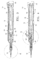
- FIG. 1 is a front, upper left perspective view of a first embodiment of the handpiece of the present invention.
- FIG. 2 is a rear, upper right perspective view of a first embodiment of the handpiece of the present invention.
- FIG. 3 is a cross-sectional view of a first embodiment of the handpiece of the present invention taken along a plane passing through the irrigation channel.
- FIG. 4 is a cross-sectional view of a first embodiment of the handpiece of the present invention taken along a plane passing through the aspiration channel.
- FIG. 5 is an enlarged partial cross-sectional view of a first embodiment of the
handpiece of the present invention taken at
circle 5 in FIG. 4. - FIG. 6 is an enlarged partial cross-sectional view of a first embodiment of the
handpiece of the present invention taken at
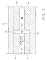
circle 6 in FIG. 3. - FIG. 7 is an enlarged cross-sectional view of a first embodiment of the handpiece
of the present invention taken at
circle 7 in FIGS. 3 and 4. - FIG. 8 is a partial cross-sectional view of a second embodiment of the handpiece of the present invention.
- FIG. 9 is an enlarged partial cross-sectional view of the second embodiment of the
handpiece of the present invention taken at
circle 9 in FIG. 8. - FIG. 10 is an enlarged partial cross-sectional view of the pumping chamber used in
the second embodiment of the handpiece of the present invention taken at
circle 10 in FIG. 9. - FIG. 11 is a partial cross-sectional view of a third embodiment of the handpiece of the present invention.
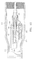
- FIG. 12 is an enlarged partial cross-sectional view of the distal end of the third
embodiment of the handpiece of the present invention taken at
circle 12 in FIG. 11. - FIG. 13 is an enlarged partial cross-sectional view of the pumping chamber used in the third embodiment of the handpiece of the present invention shown in FIGS. 11 and 12.
- FIG. 14 is a block diagram of a control system that can be used with the handpiece of the present invention.
-
-
Handpiece 10 of the present invention generally includeshandpiece body 12 andoperative tip 16.Body 12 generally includesexternal irrigation tube 18 and aspiration fitting 20.Body 12 is similar in construction to well-known in the art phacoemulsification handpieces and may be made from plastic, titanium or stainless steel. As best seen in FIG. 6,operative tip 16 includes tip/cap sleeve 26,needle 28 andtube 30.Sleeve 26 may be any suitable commercially available phacoemulsification tip/cap sleeve orsleeve 26 may be incorporated into other tubes as a multi-lumen tube.Needle 28 may be any commercially available hollow phacoemulsification cutting tip, such as the TURBOSONICS tip available from Alcon Laboratories, Inc., Fort Worth, Texas.Tube 30 may be any suitably sized tube to fit withinneedle 28, for example 29 gauge hypodermic needle tubing. - As best seen in FIG. 5,
tube 30 is free on the distal end and connected to boiling or pumpingchamber 42 on the proximal end.Tube 30 and pumpingchamber 42 may be sealed fluid tight by any suitable means having a relatively high melting point, such as a silicone gasket, glass frit or silver solder. Fitting 44 holdstube 30 withinbore 48 ofaspiration horn 46.Bore 48 communicates with fitting 20, which is journaled intohorn 46 and sealed with O-ring seal 50 to form an aspiration pathway throughhorn 46 and out fitting 20.Horn 46 is held withinbody 12 by O-ring seal 56 to formirrigation tube 52 which communicates withirrigation tube 18 atport 54. - As best seen in FIG. 7, in a first embodiment of the present invention, pumping
chamber 42 contains a relativelylarge pumping reservoir 43 that is sealed on both ends byelectrodes electrodes reservoir 43 throughtube 34 andcheck valve 53,check valves 53 being well-known in the art. Electrical current (preferably Radio Frequency Alternating Current or RFAC) is delivered to and acrosselectrodes chamber 42 through tube 30 (check valve 53 prevents the expanding fluid from entering tube 34). The expanding gas bubble pushes the surgical fluid intube 30 downstream of pumpingchamber 42 forward. Subsequent pulses of electrical current form sequential gas bubbles that move surgical fluid downtube 30. The size and pressure of the fluid pulse obtained by pumpingchamber 42 can be varied by varying the length, timing and/or power of the electrical pulse sent toelectrodes reservoir 43. In addition, the surgical fluid may be preheated prior to enteringpumping chamber 42. Preheating the surgical fluid will decrease the power required by pumpingchamber 42 and/or increase the speed at which pressure pulses can be generated. - As best seen in FIGS. 8-10, in a second embodiment of the present invention,
handpiece 110 generally includesbody 112, havingpower supply cable 113, irrigation/aspiration lines 115, pumpingchamber supply line 117.Distal end 111 ofhandpiece 110 contains pumpingchamber 142 having areservoir 143 formed betweenelectrodes Electrodes body 112 by insulatinglayer 159 such asanodized layer 159 formed onelectrodes Anodized layer 159 is less conductive than untreated aluminum and thus, acts as an electrical insulator.Electrodes electrical terminals Layer 159 may be formed by any suitable insulating or anodization technique, well-known in the art, andelectrodes electrical terminals electrodes terminals wires reservoir 143 throughsupply line 117 andcheck valve 153. Extending distally from pumpingchamber 142 isouter tube 165 that coaxially surrounds aspiration orinner tube 167.Tubes tube 30.Tube 167 is of slightly smaller diameter thantube 165, thereby forming an annular passage orgap 169 betweentube 165 andtube 167.Annular gap 169 fluidly communicates withreservoir 143. - In use, surgical fluid enters
reservoir 143 throughsupply line 117 andcheck valve 153. Electrical current is delivered to and acrosselectrodes chamber 142 throughannular gap 169. The expanding gas bubble pushes forward the surgical fluid inannular gap 169 downstream of pumpingchamber 142. Subsequent pulses of electrical current form sequential gas bubbles that move or propel the surgical fluid downannular gap 169. - One skilled in the art will recognize that the numbering in FIGS. 8-10 is identical to the numbering in FIGS. 1-7 except for the addition of "100" in FIGS. 8-10.
- As best seen in FIGS. 11-13, in a third embodiment of the present invention,
handpiece 210 generally includesbody 212, havingpower supply cable 213, irrigation/aspiration lines 215, pumpingchamber supply line 217.Distal end 211 ofhandpiece 210 contains pumpingchamber 242 having areservoir 243 formed betweenelectrodes Electrodes body 212 byanodized layer 259 formed onelectrodes Anodized layer 259 is less conductive than untreated aluminum and thus, acts as an electrical insulator.Electrodes electrical terminals Layer 259 may be formed by any suitable anodization technique, well-known in the art, andelectrodes electrical terminals electrodes terminals wires reservoir 243 thoughsupply line 217 andcheck valve 253. Extending distally from pumpingchamber 242 isouter tube 265 that coaxially surrounds aspiration orinner tube 267.Tubes tube 30.Tube 267 is of slightly smaller diameter thantube 265, thereby forming an annular passage orgap 269 betweentube 265 andtube 267.Annular gap 269 fluidly communicates withreservoir 243. - In use, surgical fluid enters
reservoir 243 throughsupply line 217 andcheck valve 253. Electrical current is delivered to and acrosselectrodes electrode 247. As the surgical fluid boils, it expands rapidly out of pumpingchamber 242 throughannular gap 269. The expanding gas bubble pushes forward the surgical fluid inannular gap 269 downstream of pumpingchamber 242. Subsequent pulses of electrical current form sequential gas bubbles that move or propel the surgical fluid downannular gap 269. - One skilled in the art will recognize that the numbering in FIGS. 11-13 is identical to the numbering in FIGS. 1-7 except for the addition of "200" in FIGS. 11-13.
- While several embodiments of the handpiece of the present invention are disclosed, any handpiece producing adequate pressure pulse force, temperature, rise time and frequency may also be used. For example, any handpiece producing a pressure pulse force of between 0.02 grams and 20.0 grams, with a rise time of between 1 gram/second and 20,000 grams/second and a frequency of between 1 Hz and 200 Hz may be used, with between 10 Hz and 100 Hz being most preferred. The pressure pulse force and frequency will vary with the hardness of the material being removed. For example, the inventors have found that a lower frequency with a higher pulse force is most efficient at debulking and removing the relatively hard nuclear material, with a higher frequency and lower pulse force being useful in removing softer epinuclear and cortical material. Infusion pressure, aspiration flow rate and vacuum limit are similar to current phacoemulsification techniques.
- As seen in FIG. 14, one embodiment of
control system 300 for use inoperating handpiece 310 includescontrol module 347, powergain RF amplifier 312 andfunction generator 314. Power is supplied toRF amplifier 312 byDC power supply 316, which preferably is an isolated DC power supply operating at several hundred volts, but typically ±200 volts.Control module 347 may be any suitable microprocessor, micro controller, computer or digital logic controller and may receive input fromoperator input device 318.Function generator 314 provides the electric wave form toamplifier 312 and typically operates at around 450 kHz or above to help minimize corrosion. - In use,
control module 347 receives input fromsurgical console 320.Console 320 may be any commercially available surgical control console such as the LEGACY® SERIES TWENTY THOUSAND® surgical system available from Alcon Laboratories, Inc., Fort Worth, Texas.Console 320 is connected to handpiece 310 throughirrigation line 322 andaspiration line 324, and the flow throughlines footswitch 326. Irrigation and aspiration flow rate information inhandpiece 310 is provided to controlmodule 347 byconsole 320 viainterface 328, which may be connected to the ultrasound handpiece control port onconsole 320 or to any other output port.Control module 347 uses footswitch 326 information provided byconsole 320 and operator input frominput device 318 to generate twocontrol signals Signal 332 is used to operatepinch valve 334, which controls the surgical fluid flowing fromfluid source 336 tohandpiece 310. Fluid fromfluid source 336 is heated in the manner described herein.Signal 330 is used to controlfunction generator 314. Based onsignal 330,function generator 314 provides a wave form at the operator selected frequency and amplitude determined by the position offootswitch 326 toRF amplifier 312 which is amplified to advance the powered wave form output to handpiece 310 to create heated, pressurized pulses of surgical fluid. - Any of a number of methods can be employed to limit the amount of heat introduced into the eye. For example, the pulse train duty cycle of the heated solution can be varied as a function of the pulse frequency so that the total amount of heated solution introduced into the eye does not vary with the pulse frequency. Alternatively, the aspiration flow rate can be varied as a function of pulse frequency so that as pulse frequency increases aspiration flow rate increases proportionally.
- This description is given for purposes of illustration and explanation. It will be apparent to those skilled in the relevant art that changes and modifications may be made to the invention described above without departing from its scope . For example, it will be recognized by those skilled in the art that the present invention may be combined with ultrasonic and/or rotating cutting tips to enhance performance.
Claims (5)
- A liquefracture handpiece for injecting a heated surgical fluid to liquefy the lens tissue of an eye, comprising:a) a body (12,112,212) having an irrigation lumen (30,34);b) a pumping chamber (42,142,242) mounted within the body, fluidly connected to the irrigation lumen, the pumping chamber being adapted to boil a small volume of the fluid so as to propel fluid downstream of the pumping chamber in said lumen, said pumping chamber being formed by a pair of electrodes (45,47,145,147,245,247) that allow electrical current to flow across the electrodes when a surgical fluid is contained within the pumping chamber, such that the pumping chamber is capable of producing a fluid pulse characterized by;i) a pressure pulse force of between 0.000196 Newtons (0.02 grams) and 0.196 Newtons (20 grams),ii) a pressure pulse rise time rate of between 0.01 Newtons/second (1 gramf/second) and 196 Newtons/second (20,000 gramf/second), andiii) a pressure pulse frequency of between 10 Hz and 100Hz.
- The handpiece of claim 1, wherein the pumping chamber defines an enlarged pumping reservoir (43,143,243) in a gap between said electrodes (45,47,145,147,245,247).
- The handpiece of claim 2, in which a check valve (53,153,253) is arranged upstream of said pumping reservoir (43,143,243).
- The handpiece of any of claims 1 to 3, wherein the size and pressure of the fluid pulse obtained by the pumping chamber (42,142,242) can be varied by varying the length, timing and/or power of an electrical pulse sent to the electrodes (45,47,145,147,245,247).
- The handpiece of any of claims 1 to 4, wherein the forward one (45) of the pair of electrodes (45,47) defines a countersink (100).
Applications Claiming Priority (3)
| Application Number | Priority Date | Filing Date | Title |
|---|---|---|---|
| US09/690,259 US6398759B1 (en) | 1998-06-04 | 2000-10-17 | Liquefracture handpiece tip |
| US690259 | 2000-10-17 | ||
| EP01203702A EP1199054B1 (en) | 2000-10-17 | 2001-09-28 | Liquefracture handpiece |
Related Parent Applications (1)
| Application Number | Title | Priority Date | Filing Date |
|---|---|---|---|
| EP01203702A Division EP1199054B1 (en) | 2000-10-17 | 2001-09-28 | Liquefracture handpiece |
Publications (2)
| Publication Number | Publication Date |
|---|---|
| EP1314409A2 true EP1314409A2 (en) | 2003-05-28 |
| EP1314409A3 EP1314409A3 (en) | 2003-07-16 |
Family
ID=24771756
Family Applications (2)
| Application Number | Title | Priority Date | Filing Date |
|---|---|---|---|
| EP01203702A Expired - Lifetime EP1199054B1 (en) | 2000-10-17 | 2001-09-28 | Liquefracture handpiece |
| EP03003909A Ceased EP1314409A3 (en) | 2000-10-17 | 2001-09-28 | Liquefracture handpiece |
Family Applications Before (1)
| Application Number | Title | Priority Date | Filing Date |
|---|---|---|---|
| EP01203702A Expired - Lifetime EP1199054B1 (en) | 2000-10-17 | 2001-09-28 | Liquefracture handpiece |
Country Status (14)
| Country | Link |
|---|---|
| US (1) | US6398759B1 (en) |
| EP (2) | EP1199054B1 (en) |
| JP (1) | JP4091282B2 (en) |
| AR (1) | AR030590A1 (en) |
| AT (1) | ATE267570T1 (en) |
| AU (1) | AU774275B2 (en) |
| BR (1) | BR0104581B1 (en) |
| CA (1) | CA2358266A1 (en) |
| DE (1) | DE60103474T2 (en) |
| DK (1) | DK1199054T3 (en) |
| ES (1) | ES2217088T3 (en) |
| IL (1) | IL145206A (en) |
| MX (1) | MXPA01009580A (en) |
| PT (1) | PT1199054E (en) |
Families Citing this family (89)
| Publication number | Priority date | Publication date | Assignee | Title |
|---|---|---|---|---|
| US8016823B2 (en) | 2003-01-18 | 2011-09-13 | Tsunami Medtech, Llc | Medical instrument and method of use |
| US7892229B2 (en) | 2003-01-18 | 2011-02-22 | Tsunami Medtech, Llc | Medical instruments and techniques for treating pulmonary disorders |
| US7549987B2 (en) | 2000-12-09 | 2009-06-23 | Tsunami Medtech, Llc | Thermotherapy device |
| US9433457B2 (en) | 2000-12-09 | 2016-09-06 | Tsunami Medtech, Llc | Medical instruments and techniques for thermally-mediated therapies |
| US8444636B2 (en) | 2001-12-07 | 2013-05-21 | Tsunami Medtech, Llc | Medical instrument and method of use |
| US20040030349A1 (en) * | 2002-08-08 | 2004-02-12 | Mikhail Boukhny | Liquefaction handpiece tip |
| US8579892B2 (en) | 2003-10-07 | 2013-11-12 | Tsunami Medtech, Llc | Medical system and method of use |
| US7276060B2 (en) * | 2004-02-26 | 2007-10-02 | Alcon, Inc. | Surgical handpiece tip |
| US7857794B2 (en) | 2004-06-14 | 2010-12-28 | Alcon, Inc. | Handpiece tip |
| US20060058823A1 (en) * | 2004-09-14 | 2006-03-16 | Dimalanta Ramon C | Handpiece pumping chamber |
| BRPI0518437A2 (en) | 2004-11-16 | 2008-11-18 | Brian Cran | lung treatment device and method |
| US20060184091A1 (en) * | 2005-02-14 | 2006-08-17 | Alcon, Inc. | Liquefaction handpiece |
| US8403951B2 (en) * | 2005-03-08 | 2013-03-26 | Novartis Ag | Phacoemulsification tip |
| US7758585B2 (en) * | 2005-03-16 | 2010-07-20 | Alcon, Inc. | Pumping chamber for a liquefaction handpiece |
| US7967799B2 (en) * | 2005-03-16 | 2011-06-28 | Alcon, Inc. | Liquefaction handpiece tip |
| US20060212037A1 (en) * | 2005-03-16 | 2006-09-21 | Alcon, Inc. | Pumping chamber for a liquefaction handpiece |
| US20070032785A1 (en) * | 2005-08-03 | 2007-02-08 | Jennifer Diederich | Tissue evacuation device |
| US9814519B2 (en) * | 2006-04-20 | 2017-11-14 | Boston Scientific Scimed, Inc. | Ablation probe with ribbed insulated sheath |
| US8287484B2 (en) * | 2006-05-02 | 2012-10-16 | Abbott Medical Optics Inc. | Multi-purpose phacoemulsification needle |
| US20070260173A1 (en) * | 2006-05-05 | 2007-11-08 | Alcon, Inc. | Irrigation/aspiration tip |
| US7993323B2 (en) | 2006-11-13 | 2011-08-09 | Uptake Medical Corp. | High pressure and high temperature vapor catheters and systems |
| US8206349B2 (en) * | 2007-03-01 | 2012-06-26 | Medtronic Xomed, Inc. | Systems and methods for biofilm removal, including a biofilm removal endoscope for use therewith |
| US7967775B2 (en) | 2007-01-09 | 2011-06-28 | Alcon, Inc. | Irrigation/aspiration tip |
| US20090032121A1 (en) * | 2007-07-31 | 2009-02-05 | Chon James Y | Check Valve |
| US7849875B2 (en) * | 2007-07-31 | 2010-12-14 | Alcon, Inc. | Check valve |
| JP5115088B2 (en) * | 2007-08-10 | 2013-01-09 | セイコーエプソン株式会社 | Surgical tool |
| US8221401B2 (en) | 2007-08-23 | 2012-07-17 | Aegea Medical, Inc. | Uterine therapy device and method |
| CN101401755B (en) * | 2007-09-28 | 2013-01-23 | 株式会社尼德克 | Head for ultrasonic operation and knife head for ultrasonic operation |
| US9924992B2 (en) | 2008-02-20 | 2018-03-27 | Tsunami Medtech, Llc | Medical system and method of use |
| DE102008025233A1 (en) | 2008-05-27 | 2009-12-03 | Erbe Elektromedizin Gmbh | Water jet surgical instrument for resection of tumor tissue in gastrointestinal tract, has jet-forming device arranged relative to nozzle such that fluid jet is adjusted by device with respect to expansion angle and/or discharge energy |
| US8721632B2 (en) | 2008-09-09 | 2014-05-13 | Tsunami Medtech, Llc | Methods for delivering energy into a target tissue of a body |
| US8579888B2 (en) | 2008-06-17 | 2013-11-12 | Tsunami Medtech, Llc | Medical probes for the treatment of blood vessels |
| US8568422B2 (en) * | 2008-09-01 | 2013-10-29 | Nigel Morlet | Cutting needle tip for surgical instrument |
| US8291933B2 (en) * | 2008-09-25 | 2012-10-23 | Novartis Ag | Spring-less check valve for a handpiece |
| US20100094270A1 (en) | 2008-10-06 | 2010-04-15 | Sharma Virender K | Method and Apparatus for Tissue Ablation |
| US10695126B2 (en) | 2008-10-06 | 2020-06-30 | Santa Anna Tech Llc | Catheter with a double balloon structure to generate and apply a heated ablative zone to tissue |
| US9561068B2 (en) | 2008-10-06 | 2017-02-07 | Virender K. Sharma | Method and apparatus for tissue ablation |
| US9561066B2 (en) | 2008-10-06 | 2017-02-07 | Virender K. Sharma | Method and apparatus for tissue ablation |
| US10064697B2 (en) | 2008-10-06 | 2018-09-04 | Santa Anna Tech Llc | Vapor based ablation system for treating various indications |
| AU2009313324A1 (en) | 2008-11-06 | 2010-05-14 | Nxthera, Inc. | Systems and methods for treatment of BPH |
| NZ592912A (en) | 2008-11-06 | 2013-08-30 | Nxthera Inc | Systems and methods for treatment of prostatic tissue |
| US9351871B2 (en) | 2008-11-12 | 2016-05-31 | Alcon Research, Ltd. | Distal plastic end infusion/aspiration tip |
| US11284931B2 (en) | 2009-02-03 | 2022-03-29 | Tsunami Medtech, Llc | Medical systems and methods for ablating and absorbing tissue |
| US9833277B2 (en) | 2009-04-27 | 2017-12-05 | Nxthera, Inc. | Systems and methods for prostate treatment |
| US8876751B2 (en) * | 2009-08-06 | 2014-11-04 | Alcon Research, Ltd. | Phacoemulsification handpiece pressure booster |
| US8900223B2 (en) | 2009-11-06 | 2014-12-02 | Tsunami Medtech, Llc | Tissue ablation systems and methods of use |
| US8568396B2 (en) * | 2009-12-10 | 2013-10-29 | Alcon Research, Ltd. | Flooded liquefaction hand piece engine |
| US9161801B2 (en) | 2009-12-30 | 2015-10-20 | Tsunami Medtech, Llc | Medical system and method of use |
| US8632530B2 (en) | 2010-03-25 | 2014-01-21 | Nxthera, Inc. | Systems and methods for prostate treatment |
| JP5887336B2 (en) | 2010-03-29 | 2016-03-16 | モーレット,ナイジェル | Improved needle tip for surgical instruments |
| US8689439B2 (en) | 2010-08-06 | 2014-04-08 | Abbott Laboratories | Method for forming a tube for use with a pump delivery system |
| US9943353B2 (en) | 2013-03-15 | 2018-04-17 | Tsunami Medtech, Llc | Medical system and method of use |
| US8377000B2 (en) | 2010-10-01 | 2013-02-19 | Abbott Laboratories | Enteral feeding apparatus having a feeding set |
| US8377001B2 (en) | 2010-10-01 | 2013-02-19 | Abbott Laboratories | Feeding set for a peristaltic pump system |
| WO2012064864A1 (en) | 2010-11-09 | 2012-05-18 | Aegea Medical Inc. | Positioning method and apparatus for delivering vapor to the uterus |
| US8784361B2 (en) | 2010-12-07 | 2014-07-22 | Alcon Research, Ltd. | Combined coaxial and bimanual irrigation/aspiration apparatus |
| WO2013016772A1 (en) | 2011-08-03 | 2013-02-07 | Nigel Morlet | Grooved needle tip for surgical instrument |
| DK2755614T3 (en) | 2011-09-13 | 2017-12-04 | Nxthera Inc | PROSTATE TREATMENT SYSTEMS |
| US9211373B2 (en) | 2011-09-23 | 2015-12-15 | Medtronic Ps Medical, Inc. | Irrigation system and clip for a surgical instrument |
| CN104135960B (en) | 2011-10-07 | 2017-06-06 | 埃杰亚医疗公司 | A kind of uterine therapy device |
| US9433725B2 (en) | 2011-12-23 | 2016-09-06 | Alcon Research, Ltd. | Combined coaxial and bimanual irrigation/aspiration apparatus |
| US10335222B2 (en) | 2012-04-03 | 2019-07-02 | Nxthera, Inc. | Induction coil vapor generator |
| US9320648B2 (en) | 2012-10-04 | 2016-04-26 | Autocam Medical Devices, Llc | Ophthalmic surgical instrument with pre-set tip-to-shell orientation |
| EP3964151A3 (en) | 2013-01-17 | 2022-03-30 | Virender K. Sharma | Apparatus for tissue ablation |
| CA2905508A1 (en) | 2013-03-14 | 2014-09-25 | Nxthera, Inc. | Systems and methods for treating prostate cancer |
| KR102240262B1 (en) | 2013-06-06 | 2021-04-14 | 알콘 인코포레이티드 | Transformer irrigation/aspiration device |
| AU2014240225A1 (en) | 2013-10-01 | 2015-04-16 | Uptake Medical Technology Inc. | Preferential volume reduction of diseased segments of a heterogeneous lobe |
| US9968395B2 (en) | 2013-12-10 | 2018-05-15 | Nxthera, Inc. | Systems and methods for treating the prostate |
| CN108635041B (en) | 2013-12-10 | 2021-04-13 | 恩克斯特拉公司 | Steam ablation system |
| WO2015179662A1 (en) | 2014-05-22 | 2015-11-26 | Aegea Medical Inc. | Integrity testing method and apparatus for delivering vapor to the uterus |
| US9993290B2 (en) | 2014-05-22 | 2018-06-12 | Aegea Medical Inc. | Systems and methods for performing endometrial ablation |
| US10485604B2 (en) | 2014-12-02 | 2019-11-26 | Uptake Medical Technology Inc. | Vapor treatment of lung nodules and tumors |
| US10342593B2 (en) | 2015-01-29 | 2019-07-09 | Nxthera, Inc. | Vapor ablation systems and methods |
| US10531906B2 (en) | 2015-02-02 | 2020-01-14 | Uptake Medical Technology Inc. | Medical vapor generator |
| BR112017024245A2 (en) | 2015-05-13 | 2018-07-17 | Nxthera, Inc. | "method for treating overactive bladder, and steam dispensing system". |
| EP3416551B1 (en) | 2016-02-19 | 2022-10-12 | Aegea Medical Inc. | Apparatus for determining the integrity of a bodily cavity |
| US11331140B2 (en) | 2016-05-19 | 2022-05-17 | Aqua Heart, Inc. | Heated vapor ablation systems and methods for treating cardiac conditions |
| CN110177508B (en) | 2016-12-21 | 2022-10-28 | 波士顿科学医学有限公司 | Steam ablation system and method |
| US10751107B2 (en) | 2017-01-06 | 2020-08-25 | Boston Scientific Scimed, Inc. | Transperineal vapor ablation systems and methods |
| US11129673B2 (en) | 2017-05-05 | 2021-09-28 | Uptake Medical Technology Inc. | Extra-airway vapor ablation for treating airway constriction in patients with asthma and COPD |
| US11344364B2 (en) | 2017-09-07 | 2022-05-31 | Uptake Medical Technology Inc. | Screening method for a target nerve to ablate for the treatment of inflammatory lung disease |
| US11350988B2 (en) | 2017-09-11 | 2022-06-07 | Uptake Medical Technology Inc. | Bronchoscopic multimodality lung tumor treatment |
| USD845467S1 (en) | 2017-09-17 | 2019-04-09 | Uptake Medical Technology Inc. | Hand-piece for medical ablation catheter |
| US11419658B2 (en) | 2017-11-06 | 2022-08-23 | Uptake Medical Technology Inc. | Method for treating emphysema with condensable thermal vapor |
| US11490946B2 (en) | 2017-12-13 | 2022-11-08 | Uptake Medical Technology Inc. | Vapor ablation handpiece |
| US11806066B2 (en) | 2018-06-01 | 2023-11-07 | Santa Anna Tech Llc | Multi-stage vapor-based ablation treatment methods and vapor generation and delivery systems |
| JP7445670B2 (en) | 2019-01-15 | 2024-03-07 | ストライカー・ユーロピアン・オペレーションズ・リミテッド | Ultrasonic Surgical Irrigation Sleeve and Related Assemblies |
| US11653927B2 (en) | 2019-02-18 | 2023-05-23 | Uptake Medical Technology Inc. | Vapor ablation treatment of obstructive lung disease |
| CN115045843B (en) * | 2022-07-05 | 2023-04-21 | 安徽省留香特种船舶有限责任公司 | Auxiliary starting mechanism and mixed delivery pump |
Citations (8)
| Publication number | Priority date | Publication date | Assignee | Title |
|---|---|---|---|---|
| US3589363A (en) | 1967-07-25 | 1971-06-29 | Cavitron Corp | Material removal apparatus and method employing high frequency vibrations |
| US4223676A (en) | 1977-12-19 | 1980-09-23 | Cavitron Corporation | Ultrasonic aspirator |
| US4246902A (en) | 1978-03-10 | 1981-01-27 | Miguel Martinez | Surgical cutting instrument |
| US4493694A (en) | 1980-10-17 | 1985-01-15 | Cooper Lasersonics, Inc. | Surgical pre-aspirator |
| US4515583A (en) | 1983-10-17 | 1985-05-07 | Coopervision, Inc. | Operative elliptical probe for ultrasonic surgical instrument and method of its use |
| US4589415A (en) | 1984-08-31 | 1986-05-20 | Haaga John R | Method and system for fragmenting kidney stones |
| US4609368A (en) | 1984-08-22 | 1986-09-02 | Dotson Robert S Jun | Pneumatic ultrasonic surgical handpiece |
| US4869715A (en) | 1988-04-21 | 1989-09-26 | Sherburne Fred S | Ultrasonic cone and method of construction |
Family Cites Families (92)
| Publication number | Priority date | Publication date | Assignee | Title |
|---|---|---|---|---|
| US1493450A (en) | 1923-05-05 | 1924-05-06 | Richardson Elizabeth | Saline heating apparatus |
| US3606878A (en) | 1968-10-04 | 1971-09-21 | Howard B Kellogg Jr | Needle instrument for extracting biopsy sections |
| US3757768A (en) | 1972-04-07 | 1973-09-11 | Medical Evaluation Devices And | Manipulable spring guide-catheter and tube for intravenous feeding |
| US3818913A (en) | 1972-08-30 | 1974-06-25 | M Wallach | Surgical apparatus for removal of tissue |
| GB1445488A (en) * | 1974-06-21 | 1976-08-11 | Wallach M | Surgical apparatus for removal of tissue |
| US3930505A (en) | 1974-06-24 | 1976-01-06 | Hydro Pulse Corporation | Surgical apparatus for removal of tissue |
| US4024866A (en) | 1974-12-02 | 1977-05-24 | Hydro Pulse Corporation | Surgical apparatus for removal of tissue |
| US3994297A (en) | 1974-12-09 | 1976-11-30 | Kopf J David | Ophthalmic instrument |
| US4169984A (en) | 1976-11-30 | 1979-10-02 | Contract Systems Associates, Inc. | Ultrasonic probe |
| US4265618A (en) | 1977-09-09 | 1981-05-05 | Solar Energy Technology, Inc. | Electrically heated endodontic syringe for injecting thermoplastic material into a root canal cavity |
| US4210146A (en) | 1978-06-01 | 1980-07-01 | Anton Banko | Surgical instrument with flexible blade |
| US4249899A (en) | 1979-02-14 | 1981-02-10 | A-Dec, Inc. | Warm water dental syringe |
| US4301802A (en) | 1980-03-17 | 1981-11-24 | Stanley Poler | Cauterizing tool for ophthalmological surgery |
| US4517977A (en) | 1981-07-24 | 1985-05-21 | Unisearch Limited | Co-axial tube surgical infusion/suction cutter tip |
| US4473077A (en) | 1982-05-28 | 1984-09-25 | United States Surgical Corporation | Surgical stapler apparatus with flexible shaft |
| JPS59200644A (en) | 1983-04-27 | 1984-11-14 | オリンパス光学工業株式会社 | Surgical incision instrument |
| US4577629A (en) | 1983-10-28 | 1986-03-25 | Coopervision, Inc. | Surgical cutting instrument for ophthalmic surgery |
| JPS61501067A (en) | 1984-01-30 | 1986-05-29 | シユレ−ゲル・ハンス−ヨアキム | Living eye lens capsule anterior wall drilling device |
| US4570632A (en) | 1984-03-16 | 1986-02-18 | Woods Randall L | Cystotome for eye surgery and method of opening lens capsule |
| US4634420A (en) | 1984-10-31 | 1987-01-06 | United Sonics Incorporated | Apparatus and method for removing tissue mass from an organism |
| US4662869A (en) | 1984-11-19 | 1987-05-05 | Wright Kenneth W | Precision intraocular apparatus |
| US4922902A (en) | 1986-05-19 | 1990-05-08 | Valleylab, Inc. | Method for removing cellular material with endoscopic ultrasonic aspirator |
| EP0232458A3 (en) | 1985-09-26 | 1988-12-14 | Alcon Instrumentation, Inc. | Multifunctional apparatus for driving powered surgical instruments |
| US4674502A (en) | 1985-09-27 | 1987-06-23 | Coopervision, Inc. | Intraocular surgical instrument |
| US4696298A (en) | 1985-11-19 | 1987-09-29 | Storz Instrument Company | Vitrectomy cutting mechanism |
| US4634419A (en) | 1985-12-13 | 1987-01-06 | Cooper Lasersonics, Inc. | Angulated ultrasonic surgical handpieces and method for their production |
| US4989588A (en) | 1986-03-10 | 1991-02-05 | Olympus Optical Co., Ltd. | Medical treatment device utilizing ultrasonic wave |
| CH670391A5 (en) | 1986-07-29 | 1989-06-15 | Sarcem Sa | |
| US4753234A (en) | 1986-11-03 | 1988-06-28 | Miguel Martinez | Surgical cutting instrument having a offset probe for ophthalmic surgery |
| SU1572614A1 (en) | 1987-04-24 | 1990-06-23 | Межотраслевой научно-технический комплекс "Микрохирургия глаза" | Device for removing lenticular masses |
| US4911161A (en) | 1987-04-29 | 1990-03-27 | Noetix, Inc. | Capsulectomy cutting apparatus |
| SE458821B (en) | 1987-09-04 | 1989-05-16 | Swedemed Ab | ULTRASOUND KNIFE |
| US4986827A (en) | 1987-11-05 | 1991-01-22 | Nestle S.A. | Surgical cutting instrument with reciprocating inner cutter |
| US4909249A (en) | 1987-11-05 | 1990-03-20 | The Cooper Companies, Inc. | Surgical cutting instrument |
| US4935006A (en) * | 1987-11-12 | 1990-06-19 | Hasson Harrith M | Suction and irrigation device with right angle and oblique openings |
| US4989583A (en) | 1988-10-21 | 1991-02-05 | Nestle S.A. | Ultrasonic cutting tip assembly |
| US4921482A (en) | 1989-01-09 | 1990-05-01 | Hammerslag Julius G | Steerable angioplasty device |
| US5037391A (en) | 1989-01-09 | 1991-08-06 | Pilot Cardiovascular Systems, Inc. | Steerable angioplasty device |
| US4998916A (en) | 1989-01-09 | 1991-03-12 | Hammerslag Julius G | Steerable medical device |
| US5203772A (en) | 1989-01-09 | 1993-04-20 | Pilot Cardiovascular Systems, Inc. | Steerable medical device |
| US5108368A (en) | 1990-01-04 | 1992-04-28 | Pilot Cardiovascular System, Inc. | Steerable medical device |
| US5372587A (en) | 1989-01-09 | 1994-12-13 | Pilot Cariovascular Systems, Inc. | Steerable medical device |
| US5308324A (en) | 1989-01-09 | 1994-05-03 | Pilot Cardiovascular Systems, Inc. | Steerable medical device |
| US5154694A (en) | 1989-06-06 | 1992-10-13 | Kelman Charles D | Tissue scraper device for medical use |
| US5019035A (en) | 1989-06-07 | 1991-05-28 | Alcon Surgical, Inc. | Cutting assembly for surgical cutting instrument |
| US5226910A (en) | 1989-07-05 | 1993-07-13 | Kabushiki Kaisha Topcon | Surgical cutter |
| US5106364A (en) | 1989-07-07 | 1992-04-21 | Kabushiki Kaisha Topcon | Surgical cutter |
| US5163433A (en) * | 1989-11-01 | 1992-11-17 | Olympus Optical Co., Ltd. | Ultrasound type treatment apparatus |
| US5223676A (en) | 1989-11-27 | 1993-06-29 | The Furukawa Electric Co., Ltd. | Composite circuit board having means to suppress heat diffusion and manufacturing method of the same |
| US5624392A (en) | 1990-05-11 | 1997-04-29 | Saab; Mark A. | Heat transfer catheters and methods of making and using same |
| US5250065A (en) | 1990-09-11 | 1993-10-05 | Mectra Labs, Inc. | Disposable lavage tip assembly |
| US5261883A (en) | 1990-10-26 | 1993-11-16 | Alcon Surgical, Inc. | Portable apparatus for controlling fluid flow to a surgical site |
| US5084012A (en) | 1991-03-22 | 1992-01-28 | Kelman Charles D | Apparatus and method for irrigation and aspiration of interior regions of the human eye |
| US5242449A (en) | 1991-04-23 | 1993-09-07 | Allergan, Inc. | Ophthalmic instrument |
| US5364405A (en) | 1991-04-23 | 1994-11-15 | Allergan, Inc. | Ophthalmic instrument with curved suction conduit and internal ultrasound needle |
| US5285795A (en) | 1991-09-12 | 1994-02-15 | Surgical Dynamics, Inc. | Percutaneous discectomy system having a bendable discectomy probe and a steerable cannula |
| US5275607A (en) | 1991-09-23 | 1994-01-04 | Visionary Medical, Inc. | Intraocular surgical scissors |
| US6210402B1 (en) * | 1995-11-22 | 2001-04-03 | Arthrocare Corporation | Methods for electrosurgical dermatological treatment |
| US6063079A (en) * | 1995-06-07 | 2000-05-16 | Arthrocare Corporation | Methods for electrosurgical treatment of turbinates |
| US5217465A (en) | 1992-02-28 | 1993-06-08 | Alcon Surgical, Inc. | Flexible and steerable aspiration tip for microsurgery |
| US5261923A (en) | 1992-04-23 | 1993-11-16 | Soares Christopher J | Method and apparatus for continuous circular capsulorehexis |
| US5308673A (en) | 1992-05-07 | 1994-05-03 | Minnesota Mining And Manufacturing Company | Stitchbonded absorbent articles and method of making same |
| US5322504A (en) | 1992-05-07 | 1994-06-21 | United States Surgical Corporation | Method and apparatus for tissue excision and removal by fluid jet |
| US5284472A (en) * | 1992-10-30 | 1994-02-08 | Allergan, Inc. | Vitreous cutter |
| US5423330A (en) | 1993-03-10 | 1995-06-13 | The University Of Miami | Capsule suction punch instrument and method of use |
| US5378234A (en) | 1993-03-15 | 1995-01-03 | Pilot Cardiovascular Systems, Inc. | Coil polymer composite |
| US5766153A (en) | 1993-05-10 | 1998-06-16 | Arthrocare Corporation | Methods and apparatus for surgical cutting |
| CA2127637C (en) | 1993-07-26 | 2006-01-03 | Scott Bair | Fluid jet surgical cutting tool |
| US5865790A (en) | 1993-07-26 | 1999-02-02 | Surgijet, Inc. | Method and apparatus for thermal phacoemulsification by fluid throttling |
| US5554155A (en) | 1994-06-03 | 1996-09-10 | Johns Hopkins University | Fiber optic pick manipulator |
| EP0778757B1 (en) * | 1994-09-02 | 2003-07-16 | Oversby Pty. Ltd. | Grooved phaco-emulsification needle |
| US5591184A (en) | 1994-10-13 | 1997-01-07 | Sentinel Medical, Inc. | Fluid jet surgical cutting instrument |
| US5616120A (en) | 1995-02-06 | 1997-04-01 | Andrew; Mark S. | Method and apparatus for lenticular liquefaction and aspiration |
| US5653692A (en) | 1995-09-07 | 1997-08-05 | Innerdyne Medical, Inc. | Method and system for direct heating of fluid solution in a hollow body organ |
| US6228078B1 (en) * | 1995-11-22 | 2001-05-08 | Arthrocare Corporation | Methods for electrosurgical dermatological treatment |
| US5624393A (en) | 1996-01-03 | 1997-04-29 | Diamond; Eric L. | Irrigation system for surgical instruments |
| US5669923A (en) | 1996-01-24 | 1997-09-23 | Gordon; Mark G. | Anterior capsulotomy device and procedure |
| US6283975B1 (en) * | 1996-07-10 | 2001-09-04 | Allergan Sales, Inc. | IOL insertion apparatus and method for making and using same |
| AUPO178796A0 (en) * | 1996-08-22 | 1996-09-12 | Oversby Pty Ltd | Intraocular irrigation/aspiration device |
| US5885243A (en) * | 1996-12-11 | 1999-03-23 | Alcon Laboratories, Inc. | Liquefaction handpiece |
| US5766194A (en) | 1996-12-23 | 1998-06-16 | Georgia Skin And Cancer Clinic, Pc | Surgical apparatus for tissue removal |
| US5879347A (en) | 1997-04-25 | 1999-03-09 | Gynecare, Inc. | Apparatus for controlled thermal treatment of tissue |
| US6179843B1 (en) * | 1997-06-28 | 2001-01-30 | Harold H. Weiler | Device for insertion of foldable intraocular lenses |
| US6139571A (en) | 1997-07-09 | 2000-10-31 | Fuller Research Corporation | Heated fluid surgical instrument |
| US6113606A (en) * | 1997-10-06 | 2000-09-05 | Dykes; Ronald E. | Incision guide for intra-ocular surgery |
| US6283974B1 (en) * | 1997-11-14 | 2001-09-04 | Aaron James Alexander | Surgical tip for phacoemulsification |
| US6146380A (en) | 1998-01-09 | 2000-11-14 | Radionics, Inc. | Bent tip electrical surgical probe |
| US6039715A (en) | 1998-05-11 | 2000-03-21 | Mackool; Richard J. | Angulated phacoemulsification needle whose outer surface converges and inner channel narrows |
| CA2269263A1 (en) * | 1998-06-04 | 1999-12-04 | Alcon Laboratories, Inc. | Control system for a liquefaction handpiece |
| US5997499A (en) | 1998-06-04 | 1999-12-07 | Alcon Laboratories, Inc. | Tip for a liquefaction handpiece |
| US6179805B1 (en) * | 1998-06-04 | 2001-01-30 | Alcon Laboratories, Inc. | Liquefracture handpiece |
| US6248111B1 (en) * | 1999-08-06 | 2001-06-19 | Allergan Sales, Inc. | IOL insertion apparatus and methods for using same |
-
2000
- 2000-10-17 US US09/690,259 patent/US6398759B1/en not_active Expired - Lifetime
-
2001
- 2001-08-21 AU AU63579/01A patent/AU774275B2/en not_active Ceased
- 2001-08-30 IL IL145206A patent/IL145206A/en not_active IP Right Cessation
- 2001-08-31 AR ARP010104166A patent/AR030590A1/en active IP Right Grant
- 2001-09-24 MX MXPA01009580A patent/MXPA01009580A/en active IP Right Grant
- 2001-09-28 DK DK01203702T patent/DK1199054T3/en active
- 2001-09-28 ES ES01203702T patent/ES2217088T3/en not_active Expired - Lifetime
- 2001-09-28 PT PT01203702T patent/PT1199054E/en unknown
- 2001-09-28 DE DE60103474T patent/DE60103474T2/en not_active Expired - Lifetime
- 2001-09-28 EP EP01203702A patent/EP1199054B1/en not_active Expired - Lifetime
- 2001-09-28 EP EP03003909A patent/EP1314409A3/en not_active Ceased
- 2001-09-28 JP JP2001300325A patent/JP4091282B2/en not_active Expired - Fee Related
- 2001-09-28 AT AT01203702T patent/ATE267570T1/en active
- 2001-10-04 CA CA002358266A patent/CA2358266A1/en not_active Abandoned
- 2001-10-17 BR BRPI0104581-4A patent/BR0104581B1/en not_active IP Right Cessation
Patent Citations (8)
| Publication number | Priority date | Publication date | Assignee | Title |
|---|---|---|---|---|
| US3589363A (en) | 1967-07-25 | 1971-06-29 | Cavitron Corp | Material removal apparatus and method employing high frequency vibrations |
| US4223676A (en) | 1977-12-19 | 1980-09-23 | Cavitron Corporation | Ultrasonic aspirator |
| US4246902A (en) | 1978-03-10 | 1981-01-27 | Miguel Martinez | Surgical cutting instrument |
| US4493694A (en) | 1980-10-17 | 1985-01-15 | Cooper Lasersonics, Inc. | Surgical pre-aspirator |
| US4515583A (en) | 1983-10-17 | 1985-05-07 | Coopervision, Inc. | Operative elliptical probe for ultrasonic surgical instrument and method of its use |
| US4609368A (en) | 1984-08-22 | 1986-09-02 | Dotson Robert S Jun | Pneumatic ultrasonic surgical handpiece |
| US4589415A (en) | 1984-08-31 | 1986-05-20 | Haaga John R | Method and system for fragmenting kidney stones |
| US4869715A (en) | 1988-04-21 | 1989-09-26 | Sherburne Fred S | Ultrasonic cone and method of construction |
Also Published As
| Publication number | Publication date |
|---|---|
| EP1199054B1 (en) | 2004-05-26 |
| BR0104581B1 (en) | 2012-01-24 |
| AU774275B2 (en) | 2004-06-24 |
| IL145206A (en) | 2006-12-10 |
| JP2002153500A (en) | 2002-05-28 |
| JP4091282B2 (en) | 2008-05-28 |
| AU6357901A (en) | 2002-04-18 |
| IL145206A0 (en) | 2002-06-30 |
| CA2358266A1 (en) | 2002-04-17 |
| AR030590A1 (en) | 2003-08-27 |
| DE60103474T2 (en) | 2005-06-16 |
| EP1199054A1 (en) | 2002-04-24 |
| US6398759B1 (en) | 2002-06-04 |
| EP1314409A3 (en) | 2003-07-16 |
| BR0104581A (en) | 2002-09-24 |
| DE60103474D1 (en) | 2004-07-01 |
| MXPA01009580A (en) | 2002-04-24 |
| DK1199054T3 (en) | 2004-09-27 |
| PT1199054E (en) | 2004-09-30 |
| ATE267570T1 (en) | 2004-06-15 |
| ES2217088T3 (en) | 2004-11-01 |
Similar Documents
| Publication | Publication Date | Title |
|---|---|---|
| US6206848B1 (en) | Liquefracture handpiece | |
| EP1199054B1 (en) | Liquefracture handpiece | |
| CA2382533C (en) | Liquefracture handpiece | |
| US6676628B2 (en) | Pumping chamber for a liquefracture handpiece | |
| US6589201B1 (en) | Liquefracture handpiece tip | |
| US6579270B2 (en) | Liquefracture handpiece tip | |
| US5989212A (en) | Pumping chamber for a liquefaction handpiece having a countersink electrode | |
| US6860868B1 (en) | Surgical handpiece | |
| US6315755B1 (en) | Method of controlling a liquefracture handpiece | |
| EP0962204A1 (en) | Control system for a liquefaction handpiece |
Legal Events
| Date | Code | Title | Description |
|---|---|---|---|
| PUAI | Public reference made under article 153(3) epc to a published international application that has entered the european phase |
Free format text: ORIGINAL CODE: 0009012 |
|
| 17P | Request for examination filed |
Effective date: 20030221 |
|
| AC | Divisional application: reference to earlier application |
Ref document number: 1199054 Country of ref document: EP Kind code of ref document: P |
|
| AK | Designated contracting states |
Designated state(s): AT BE CH CY DE DK ES FI FR GB GR IE IT LI LU MC NL PT SE TR |
|
| AX | Request for extension of the european patent |
Extension state: AL LT LV MK RO |
|
| PUAL | Search report despatched |
Free format text: ORIGINAL CODE: 0009013 |
|
| AK | Designated contracting states |
Designated state(s): AT BE CH CY DE DK ES FI FR GB GR IE IT LI LU MC NL PT SE TR |
|
| AX | Request for extension of the european patent |
Extension state: AL LT LV MK RO |
|
| 17Q | First examination report despatched |
Effective date: 20030910 |
|
| AKX | Designation fees paid |
Designated state(s): AT BE CH CY DE DK ES FI FR GB GR IE IT LI LU MC NL PT SE TR |
|
| STAA | Information on the status of an ep patent application or granted ep patent |
Free format text: STATUS: THE APPLICATION HAS BEEN REFUSED |
|
| 18R | Application refused |
Effective date: 20040611 |