BACKGROUND OF THE INVENTION
Field of the Invention
This invention relates to packet transmission apparatuses
and packet transmission processing methods, and more particularly,
to packet transmission apparatuses and packet transmission
processing methods that enable priority control and bandwidth
control for packets.
Description of the Background Art
In recent years, distribution of moving images or bi-directional
communications of video via the Internet has become
prevalent. Real time communications such as the distribution of
moving images and bi-directional communications of video are
sensitive to packet delays and delay jitter between the
transmitting end and the receiving end. Thus, it is necessary
to perform traffic priority control in order to carry out real
time communications via networks such as the Internet. An example
of traffic priority control is Diffserv (Differentiated Service)
described in RFC 2475 of the IETF (Internet Engineering Task
Force) . In Diffserv, packets are classified by MFC (Multi Field
Classifier) when they enter a network, and a DSCP (Differentiated
Service Code Point) is set in a header of each classified packet.
Then, each packet is transferred over the network based on the
forwarding behavior associated with the DSCP.
FIG. 17 is a schematic diagram illustrating the header
format of IPv4 (Internet Protocol Version 4), and FIG. 18 is a
schematic diagram illustrating the header format of IPv6
(Internet Protocol Version 6). The DSCP redefines the TOS field
shown in FIG. 17, and the traffic class field shown in FIG. 18
(see the hatched portions shown in both figures).
FIG. 19 is a schematic diagram illustrating the structure
of the DSCP. In FIG. 19, the DSCP contains 8 bits, among which
the first 6 bits are used to represent a PHB (Per Hop Behavior),
i.e., a forwarding operation, and the other 2 bits are CU
(Currently Unused), i.e., undefined. PHBs are classified into
the following three classes: a BE (Best Effort) class (000000),
an EF (Expedited Forwarding) class (101110), and an AF (Assured
Forwarding) class. Generally, the PHBs classified in the BE class
are used for uncontrolled services; the PHBs classified in the
EF classes for services which require smaller packet delays and
delay jitter (for example, virtual leased line services) ; and the
PHBs classified in the AF classes for services which guarantee
a minimum bandwidth through statistical multiplexing. In the AF
class, four classes and three levels of discard priorities are
currently defined, and the order of IP packets within the same
AF class is guaranteed. FIG. 20 is a table showing values of a
recommended AF-class PHB. As shown in the row direction of FIG.
20, priorities are classified into four classes, among which class
1 has the highest priority. Similarly, the column direction of
FIG. 20 represents three levels of discard priorities. Packets
having discard priority 1 are most unlikely to be discarded.
According to Diffserv as described above, a packet switch
can process a given packet with a higher level of priority by
setting a DSCP so as to give priority to the forwarding of the
real time traffic.
Furthermore, IEEE (Institute of Electrical and Electronics
Engineers) 802. 1Q/p describes definitions of packets that need
to be treated with priority in a datalink layer. FIG. 21 is a
schematic diagram illustrating the structures of an Ethernet
frame and a tag control information field thereof as defined under
IEEE 802. 1Q/p. In FIG. 21, the Ethernet frame includes a VLAN
tag, in which a tag control information (TCI) field is included.
The most significant 3 bits of this field are used for representing
a priority level, thereby enabling the Ethernet frame to have one
of eight different levels of priorities.
Each packet assigned with a priority as described above is
generally forwarded through the network in accordance with PQ
(Priority Queuing). Specifically, according to PQ, a number of
queues corresponding to different levels of priority are provided
in a packet switch. Each packet which arrives at the packet switch
is stored in a queue corresponding to its priority level. Then,
according to a predetermined timing, the packet switch selects
the highest priority queue that includes a packet therein, and
fetches the packet therefrom so as to be sent over the network.
Furthermore, when traffic streams from a plurality of users
are multiplexed to one link, an assured bandwidth which is
available to each user is set. To ensure that the above-described
assured bandwidth is actually available to each user, bandwidth
control is required. In performing bandwidth control, WRR
(Weighted Round Robin) or WFQ (Weighted Fair Queuing) are
generally used. WRR is a round-robin service scheme in which a
queue is provided to each session; a weighting parameter
proportionate to the required bandwidth is assigned to the session
queue; and a plurality of session queues are sequentially selected
based on their weighting parameters. WRR has an advantage in
terms of fairness because it is based on a round-robin service.
On the other hand, WFQ is a bit-by-bit round-robin service scheme
in which each received packet is assigned with a tag indicating
a time to lapse before completion of the service such that packets
having smaller tags are outputted first. WFQ has an advantage
in terms of fairness and bandwidth utilization.
Furthermore, besides the priority control and bandwidth
control described above, EP 1 058 424 A2 discloses a bandwidth
monitoring device for effectively utilizing remaining bandwidth.
The disclosed bandwidth monitoring device is installed in a router
accommodated in a network. In the bandwidth monitoring device,
a monitoring result determination section determines whether the
bandwidth of a priority packet is narrower than the contracted
bandwidth or not. When it is determined that the bandwidth of
the priority packet is narrower than the contracted bandwidth,
a DSCP determination section transmits a non-priority packet as
a priority packet, thus utilizing the remaining bandwidth for
transmission of non-priority packets. As a result, it is possible
to effectively utilize the contracted bandwidth.
However, in accordance with the conventional bandwidth
monitoring device, the DSCP determination section may set a value
representing a priority packet in the priority field of a
non-priority packet. Therefore, a bandwidth monitoring device
installed in any subsequent router in the network cannot determine
whether the received priority packet has always been a priority
packet, or it has been converted into a priority packet by the
router by which the packet was transmitted. That is, each packet
may lose its original priority. If traffic congestion occurs in
the subsequent router, the router cannot perform priority control
based on the original priority of each packet. Specifically, when
a packet that was originally a non-priority packet is transmitted
as a priority packet, another packet that was originally a
priority packet may have a delayed arrival at the receiving end,
or delay jitter may result, thereby causing degradation in
transmission quality.
SUMMARY OF THE INVENTION
Therefore, an object of the present invention is to provide
a packet transmission apparatus which performs priority control
with excellent transmission quality while assuring a contracted
bandwidth.
In order to attain the object mentioned above, a first
aspect of the present invention is directed to a packet
transmission apparatus for performing a predetermined process on
packets transferred over a plurality of input links, and
outputting the packets to an output link, comprising: an
identifier assigning section for, after receiving a packet
transferred over each input link, assigning one of first to third
identifiers to the received packet, wherein the first identifier
indicates that the packet has a relatively high priority and does
not exceed an assured bandwidth determined with a predetermined
method, the second identifier indicates that the packet has a
relatively low priority and does not exceed the assured bandwidth,
and the third identifier at least indicates that the packet
exceeds the assured bandwidth, the packet transmission apparatus
further comprising: a packet transmitting section for performing
a necessary process on the packet assigned with one of the first
to third identifiers by the identifier assigning section, and
outputting the processed packet to the output link.
These and other objects, features, aspects and advantages
of the present invention will become more apparent from the
following detailed description of the present invention when
taken in conjunction with the accompanying drawings.
BRIEF DESCRIPTION OF THE DRAWINGS
FIG. 1 is a schematic diagram illustrating an exemplary
structure of a network system 1 for apartment buildings according
to a first embodiment of the present invention;
FIG. 2 is a block diagram showing the structure of each home
GW 22 shown in FIG. 1;
FIG. 3 is a schematic diagram for illustrating a token
bucket meter method used in a bandwidth monitoring section 213
shown in FIG. 2;
FIG. 4 is a flowchart illustrating a process performed by
an identifier assigning section 214 shown in FIG. 2;
FIG. 5 is a block diagram illustrating the structure of each
intra-building GW 3 shown in FIG. 1;
FIG. 6 is a block diagram illustrating the structure of each
inter-building GW 5 shown in FIG. 1;
FIG. 7 is a block diagram illustrating an exemplary
structure of a network system 11 for apartment buildings according
to a second embodiment of the present invention;
FIG. 8 is a block diagram illustrating the detailed
structure of a home GW 122 shown in FIG. 7;
FIG. 9 is a flowchart illustrating a process performed by
an identifier assigning section 14 shown in FIG. 8;
FIG. 10 is a block diagram illustrating the structure of
each inter-building GW 13 shown in FIG. 7;
FIG. 11 is a graph representing a discard probability of
packets Pe according to RIO (Red with In and Out);
FIG. 12 is a block diagram illustrating the structure of
each inter-building GW 15 shown in FIG. 7;
FIG. 13 is a schematic diagram illustrating an exemplary
structure of a network system 31 for apartment buildings according
to a third embodiment of the present embodiment;
FIG. 14 is a block diagram illustrating the detailed
structure of a home GW 322 shown in FIG. 13;
FIG. 15 is a schematic diagram illustrating an exemplary
structure of a conversion table 35 used by a packet transmitting
section 34 shown in FIG. 14;
FIG. 16 is a block diagram illustrating the detailed
structure of an L2 switch 33 shown in FIG. 13;
FIG. 17 is a schematic diagram illustrating a header format
of IPv4 (Internet Protocol Version 4);
FIG. 18 is a schematic diagram illustrating a header format
of IPv6 (Internet Protocol Version 6);
FIG. 19 is a schematic diagram illustrating the structure
of a DSCP (Differentiated Service Code Point);
FIG. 20 is a table showing values of a recommended AF
(Assured Forwarding)-class PHB (Per Hop Behavior); and
FIG. 21 is a schematic diagram illustrating the structures
of an Ethernet frame and a tag control information field thereof
as defined under IEEE (Institute of Electrical and Electronics
Engineers) 802. 1Q/p.
DESCRIPTION OF THE PREFERRED EMBODIMENTS
(first embodiment)
FIG. 1 is a schematic diagram illustrating an exemplary
structure of a network system 1 for apartment buildings according
to a first embodiment of the present invention. The network
system shown in FIG. 1 is typically installed in apartment
buildings, and includes a plurality of user-privately-owned
networks 2, at least one intra-building gateway (hereinafter
referred to as "intra-building GW") 3, a plurality of
interconnection links 4 for connecting the user-privately-owned
networks 2 and the intra-building GW 3, and at least one
inter-building gateway (hereinafter referred to as "inter-building
GW") 5. Each user-privately-owned network 2 is
typically installed in one of the apartments comprised in an
apartment building, and includes at least one terminal 21 (two such
terminals are shown in FIG. 1), at least one home gateway
(hereinafter referred to as "home GW") 22, and a plurality of
interconnection links 23. In accordance with a communications
protocol such as the Internet protocol, the home GW 22 carries
out communications with each terminal 21 accommodated in the same
user-privately-owned network 2 via the interconnection links 23.
The intra-building GW 3 is connected with the respective home GWs
22 installed in the same apartment building via the plurality of
interconnection links 4, and carries out communications with the
home GWs 22 in accordance with the aforementioned communications
protocol. The inter-building GW 5 is connected with each
intra-building GW 3 installed in the same apartment building via
a shared link 6, and carries out communications with the
intra-building GW 3 in accordance with the aforementioned
communications protocol. Furthermore, the inter-building GW 5
is connected with an external network 7 such as the Internet via
a shared link 8 for sending packets defined under the
aforementioned communications protocol, and receiving packets
which have been transferred over the external network 7. Thus,
the home GWs 22 share an uplink bandwidth (i.e., a bandwidth for
uplink) of the shared link 6 and an uplink bandwidth of the shared
link 8 among themselves. Note that a downlink bandwidth (i.e.,
a bandwidth for downlink) thereof is of no particular importance
to the present embodiment, and therefore the description thereof
is omitted.
In FIG. 1, it is assumed that the number of home GWs 22
accommodated in the network system 1 is four, and the bandwidth
BW of the shared link 6 is 100 Mbps. It is further assumed that
the shared link 6 is used by the home GWs 22 on an impartial basis.
Based on these assumptions, the assured bandwidth ABa of each home
GW 22 is 25 Mbps (=100 Mbps/4). As such, the assured bandwidth
ABa of each home GW 22 is so set that the sum total of the bandwidth
ABa of home GWs 22 is equal to or smaller than the bandwidth BW
of the shared link 6.
Next, the structure of the component elements of the network
system 1 will be described in detail. FIG. 2 is a block diagram
showing the structure of each GW 22 shown in FIG. 1. In FIG. 2,
the home GW 22 includes a packet transmission apparatus 24, which
comprises a packet receiving section 25, a routing section 26,
a transmission control section 27, and a packet transmitting
section 28. The packet receiving section 25 receives a packet
Pa which has been transferred from the terminals 21 accommodated
in the same user-privately-owned network 2 via the
interconnection links 23 (which are exemplary of the "input links"
recited in the claims). The packet receiving section 25 passes
the received packet Pa to the routing section 26.
The routing section 26 performs routing in accordance with
a routing table previously stored therein for changing a
destination IP address (see FIGS. 17 and 18) of the packet Pa
received from the packet receiving section 25. The routing
section 26 passes the modified packet Pa to the transmission
control section 27 as a packet Pb.
The transmission control section 27 performs transmission
control for each received packet Pb. In order to perform
transmission control, as shown in FIG. 2, the transmission control
27 includes a packet classification section 29, a priority queue
210, a non-priority queue 211, a scheduling section 212, a
bandwidth monitoring section 213, and an identifier assigning
section 214.
The packet classification section 29 receives packets Pb
from the routing section 26. After receiving a packet Pb, the
packet classification section 29 performs a packet classification
process on the currently-received packet Pb to add the packet to
either the priority queue 210 or the non-priority queue 211.
Several examples of a packet classification process are next
described.
In a first example, some of the terminals 21 accommodated
in the user-privately-owned network 2 may be previously
determined to send real time data. As used herein, real time data
is data which needs to be processed in real time, and may typically
be video data or audio data. Furthermore, in each packet Pa which
is assembled in a terminal 21, the packet's IP address is described
as a source IP address (see FIGS. 17 and 18). Under such
circumstances, the IP addresses of any terminals 21 sending real
time data are registered in the packet classification section 29.
When the source IP address of a received packet Pb coincides with
any pre-registered IP address, the packet classification section
29 adds the currently-received packet Pb to the priority queue
210. On the other hand, when the source IP address of the received
packet Pb does not coincide with any pre-registered IP address,
the packet classification section 29 adds the currently-received
packet Pb to the non-priority queue 211.
In a second example, each terminal 21 may have a plurality
of ports in order to enable communications with a plurality of
other terminals. Furthermore, a terminal 21 may use only a
predetermined port to output real time data. Under such
circumstances, a combination of an IP address of a terminal 21
outputting real time data and a number assigned to its dedicated
port for real time data transmission is registered in the packet
classification section 29. When the combination of a source IP
address and a port number of the received packet Pb coincide with
the registered IP address and port number, the packet
classification section 29 adds the currently-received packet Pb
to the priority queue 210. On the other hand, when a source IP
address and a port number of the received Pb does not coincide
with the registered combination of an IP address and a port number,
the packet classification section 29 adds the currently-received
packet Pb to the non-priority queue 211.
In a third example, the terminals 21 may assemble a packet
Pa whose payload is composed of real time data. Generally, for
real time communications which are sensitive with respect to
packet delays and delay jitter, a transport protocol called a UDP
(User Datagram Protocol), which does not perform congestion
control and flow control, is used. Alternatively, for non-real
time data communications, a protocol called a TCP (Transmission
Control Protocol), which performs congestion control and flow
control to guarantee reliable communications, is often used.
When real time communications are carried out based on the UDP
in accordance with IPv4, a UDP protocol number is described in
the protocol field (see FIG. 17) of the packet Pa. The transport
protocol number as such is registered in the packet classification
section 29. When it is determined that a transport protocol
number of the received packet Pb coincides with a registered
transport number, the packet classification section 29 adds the
currently-received packet Pb to the priority queue 210. On the
other hand, when it is determined that a transport protocol number
of the received packet Pb does not coincide with the registered
transport number, the packet classification section 29 adds the
currently-received packet Pb to the non-priority queue 211.
Alternatively, when real time communications are carried out
using on the UDP in accordance with IPv6, a transport protocol
number is described in the next header field (see FIG. 18) of the
packet Pa. Thus, even when real time communications are carried
out in accordance with IPv6, the packet classification section
29 can perform packet classification as in the case of conforming
to Ipv4. Furthermore, the packet classification section 29 can
also classify packets Pb forwarded in accordance with IPv6 by
referring to the flow field (see FIG. 18).
In a fourth example, the terminals 21 may describe a DSCP
value representing any of a plurality of PHBs (see FIG. 20) in
a packet Pa for outputting. As described in the section entitled
"Description of the Background Art", PHBs represent different
classes. Among these classes, for example, an EF class requires
reduced delay times, i.e., real time processing. Classes
requiring such real time processing may be registered in the
packet classification section 29. When a DSCP value of the
received packet Pb coincides with a registered class, the packet
classification section 29 adds the currently-received packet Pb
to the priority queue 210. On the other hand, when a PHB of the
received packet Pb does not coincide with the registered class,
the currently-received packet Pb is added to the non-priority
queue 211.
In a fifth example, the packet classification section 29
can measure a bit rate (i.e., currently used bandwidth) of an
inputted packet Pb by using a method such as a token bucket method,
which will be described further below. When a measured traffic
flow of the packet Pb has a constant bit rate (hereinafter referred
to as "CBR"), the packet classification section 29 adds the
currently-received packet Pb to the priority queue 210. On the
other hand, when a measured traffic flow of the packet Pb does
not have a CBR, the currently-received packet Pb is added to the
non-priority queue 211.
According to each method described above, packets Pb to be
forwarded with priority, e.g., real time data, are added to the
priority queue 210, and packets Pb that are not required to be
forwarded with priority are added to the non-priority queue 211.
For convenience of description, packets Pb which are added to the
priority queue 210 will be referred to as "priority packets PPb",
and packets which are added to the non-priority queue 211 will
be referred to as "non-priority packets NPb".
The scheduling section 212 performs a process in accordance
with PQ (Priority Queuing) according to a predetermined timing.
When the process is performed, the scheduling section 212 first
determines whether the priority queue 210 includes any priority
packets PPb or not. When the priority queue includes a priority
packet PPb, the scheduling section 212 extracts one priority
packet PPb from the priority queue 210. The scheduling section
212 passes priority information PI to the identifier assigning
section 214, and passes the extracted priority packet PPb to the
bandwidth monitoring section 213. As used herein, the priority
information PI is information indicating that a priority packet
PPb has been extracted from the priority queue 210, i.e.,
information indicating that the extracted packet has a high
priority.
Furthermore, when the priority queue 210 includes no
priority packets PPb, the scheduling section 212 determines
whether the non-priority queue 211 includes any non-priority
packets NPb or not. When the non-priority queue 211 includes a
non-priority packet NPb, the scheduling section 212 extracts one
non-priority packet NPb from the non-priority queue 211. The
scheduling section 212 passes non-priority information NPI to the
identifier assigning section 214, and passes the extracted
non-priority packet NPb to the bandwidth monitoring section 213.
As used herein, the non-priority information NPI is information
indicating that a non-priority packet NPb has been extracted from
the non-priority queue 211, i.e., information indicating that the
extracted packet has a low priority.
Note that, when no priority packets PPb are included in the
priority queue 210 and no non-priority packets NPb are included
in the non-priority queue 211, the scheduling section 212 waits
for a reoccurrence of the predetermined timing.
The bandwidth monitoring section 213 determines whether a
packet Pb (either a priority packet PPb or a non-priority packet
NPb) received from the scheduling section 212 can be forwarded
within the above-described assured bandwidth ABa or not.
Furthermore, when it is determined that the received packet Pb
can be forwarded within the assured bandwidth ABa, the bandwidth
monitoring section 213 generates in-assured band information IB
indicating that the received packet Pb can be forwarded within
the assured bandwidth ABa, and passes the in-assured band
information IB to the identifier assigning section 214. On the
other hand, when it is determined that the received packet Pb
cannot be forwarded within the assured bandwidth ABa, the
bandwidth monitoring section 213 generates out-of-assured
bandwidth information OB indicating that the received packet Pb
cannot be forwarded within the assured bandwidth ABa, and passes
the out-of-assured bandwidth information OB to the identifier
assigning section 214.
To perform the above-described determination process, the
bandwidth monitoring section 213 uses either priority information
PI or non-priority information NPI, which is received from the
scheduling section 212 at substantially the same time that the
packet PPb or NPb is received, and employs the token bucket meter
method. FIG. 3 is a schematic diagram illustrating the token
bucket meter method. In FIG. 3, the token bucket meter method
is a version of a so-called token bucket algorithm extended so
that a single token bucket 215 is shared in both the priority queue
210 and the non-priority queue 211. Tokens are accumulated in
the token bucket 215 at a rate corresponding to the assured
bandwidth ABa, no more than to a level corresponding to the depth
BD of the token bucket 215, which is predetermined. Furthermore,
a threshold value TH that is smaller than the depth BD is set in
the token bucket 215 so as to allow the priority packets PPb to
obtain tokens with a higher priority than the non-priority packet
NPb.
When receiving the priority information PI from the
scheduling section 212, the bandwidth monitoring section 213
determines whether an amount of tokens corresponding to a packet
length of a substantially concurrently-received priority packet
PPb has been accumulated in the token bucket 215 or not. When
it is determined that a sufficient amount of tokens corresponding
to the packet length of the priority packet PPb has been
accumulated, the bandwidth monitoring section 213 obtains the
amount of tokens corresponding to the packet length from the token
bucket 215, and accordingly reduces the amount of tokens in the
token bucket 215. Furthermore, in this case, the bandwidth
monitoring section 213 generates in-assured bandwidth
information IB. Thereafter, the bandwidth monitoring section
213 passes the generated in-assured bandwidth information IB and
the currently-received priority packet PPb to the identifier
assigning section 214. On the other hand, when it is determined
that an amount of tokens corresponding to the packet length of
the priority packet PPb has not been accumulated, the bandwidth
monitoring section 213 generates out-of-assured bandwidth
information OB without obtaining tokens. Thereafter, the
bandwidth monitoring section 213 passes the generated out-of-assured
bandwidth information OB and the currently-received
priority packet PPb to the identifier assigning section 214.
Furthermore, when the non-priority information NPI is
received from the scheduling section 212, the bandwidth
monitoring section 213 first determines whether tokens have been
accumulated in the token bucket 215 to a level that is equal to
or greater than the threshold value TH or not. Only when it is
determined that tokens have been accumulated in the token bucket
215 to a level that is equal to or greater than the threshold value
TH, does the bandwidth monitoring section 213 determine whether
an amount of tokens corresponding to the packet length of a
substantially concurrently-received non-priority packet NPb has
been accumulated in the token bucket 215 or not. When it is
determined that a sufficient amount of tokens corresponding to
the packet length of the non-priority packet NPb has been
accumulated, the bandwidth monitoring section 213 obtains the
amount of tokens corresponding to the packet length from the token
bucket 215, and accordingly reduces the amount of tokens in the
token bucket 215. Furthermore, the bandwidth monitoring section
213 generates in-assured bandwidth information IB. Thereafter,
the bandwidth monitoring section 213 passes the generated in-assured
bandwidth information IB and the currently-received
non-priority packet NPb to the identifier assigning section 214.
On the other hand, when it is determined that tokens have not been
accumulated to a level that is equal to or greater than the
threshold value TH, or an amount of tokens corresponding to the
packet length has not been accumulated, the bandwidth monitoring
section 213 generates out-of-assured bandwidth information OB
without obtaining tokens. Thereafter, the bandwidth monitoring
section 213 passes the generated out-of-assured bandwidth
information OB and the currently-received non-priority packet NPb
to the identifier assigning section 214.
As described above, by setting a threshold value TH in the
token bucket 215, the probability of generating in-assured
bandwidth information IB becomes higher than the probability of
generating out-of-assured bandwidth information OB. Thus, it is
possible to forward each priority packet PPb to the receiving end
with smaller packet delays and smaller delay jitter, as will be
described in detail further below.
The identifier assigning section 214 receives either
priority information PI or non-priority information NPI from the
scheduling section 212. Furthermore, the identifier assigning
section 214 receives, at substantially the same time that the
priority information PI is received, a combination of the priority
packet PPb and either the in-assured bandwidth information IB or
the out-of-assured bandwidth information OB from the bandwidth
monitoring section 213. Furthermore, the identifier assigning
section 214 receives, at substantially the same time that the
non-priority information NPI is received, a combination of the
non-priority packet NPb and either the in-assured bandwidth
information IB or the out-of-assured bandwidth information OB
from the bandwidth monitoring section 213.
After receiving the combination of data as described above,
the identifier assigning section 214 performs an identifier
assigning process to assign one of the following identifiers: a
first priority identifier (hereinafter referred to as "AF11"),
a second priority identifier (hereinafter referred to as "AF21"),
and a third priority identifier (hereinafter referred to as
"AF31") to the currently-received packet Pb. FIG. 4 is a
flowchart illustrating the process performed by the identifier
assigning section 214. Referring to FIG. 4, the identifier
assigning section 214 first determines whether the currently-received
information is priority information PI or non-priority
information NPI (step S01).
When it is determined at step S01 that the received
information is priority information PI, the identifier assigning
section 214 determines whether the received priority information
PI is in-assured bandwidth information IB or out-of-assured
bandwidth information OB (step S02).
When it is determined at step S02 that the received priority
information PI is in-assured bandwidth information IB, the
identifier assigning section 214 assigns AF11 to the
currently-received priority packet PPb (step S03). AF11 is an
identifier indicating that the received priority packet has a high
priority and can be forwarded within the assured bandwidth ABa;
in other words, the identifier AF11 is a combination of priority
information PI and in-assured bandwidth information IB.
Furthermore, AF11 is preferably described in the type of service
field (see FIG. 17) when a priority packet PPb is forwarded in
accordance with IPv4, and preferably described in the traffic
class field (see FIG. 18) when a priority packet PPb is forwarded
in accordance with IPv6. More preferably, the DSCP value of AF11
(i.e., the most significant 6 bits of the type of service and
traffic class fields) is "001010".
When it is determined at step S02 that the received priority
information PI is out-of-assured bandwidth information OB, the
identifier assigning section 214 assigns AF31 to the received
priority packet PPb (step S04). Thus, AF31 is an identifier
indicating that the received priority packet cannot be forwarded
within the assured bandwidth ABa; in other words, AF31 is an
identifier at least including out-of-assured bandwidth
information OB. Furthermore, as is the case with AF11, AF31 is
preferably described in either the type of service or traffic
class field. The DSCP value of AF31 is preferably "011010".
On the other hand, when it is determined at step S01 that
the received information is non-priority information NPI, the
identifier assigning section 214 determines whether the received
priority information NPI is in-assured bandwidth information IB
or out-of-assured bandwidth information OB similarly to step S02
(step S05).
When it is determined at step S05 that the received
non-priority information NPI is in-assured bandwidth information
IB, the identifier assigning section 214 assigns the above-described
AF21 to the received non-priority packet NPb (step S06).
Thus, AF21 is an identifier indicating that the received priority
packet has a low priority but can be forwarded within the assured
bandwidth ABa; in other words, the identifier AF21 is a
combination of non-priority information NPI and in-assured
bandwidth information IB. Furthermore, as is the case with AF11,
AF21 is preferably described in either the type of service or
traffic class field. The DSCP value of AF21 is preferably
"010010".
On the other hand, when it is determined at step S05 that
the received non-priority information NPI is out-of-assured
bandwidth information OB, the identifier assigning section 214
assigns AF31 to the received non-priority packet NPb (step S07).
After the received packet has been processed in one of steps
S03, S04, S06, and S07, the identifier assigning section 214
passes the priority packet PPb or the non-priority packet NPb that
has been processed therein to the packet transmitting section 28
as a packet Pc (step S08). After passing the packet Pc to the
packet transmitting section 28, the identifier assigning section
214 waits until receiving another combination of information.
The packet transmitting section 28 performs a necessary
process on the received packet Pc, and outputs the processed
packet Pc as a packet Pd to the interconnection link 4 (which is
exemplary of the "output link" recited in the claims). The
outputted packet Pd is transferred over the interconnection link
4 and received by the intra-building GW 3.
FIG. 5 is a block diagram illustrating the structure of each
intra-building GW 3 shown in FIG. 1. In FIG. 5, the intra-building
GW 3 includes a packet transmission apparatus 216. The packet
transmission apparatus 216 differs from the packet transmission
apparatus 24 only in that a transmission control section 217 is
provided instead of a transmission control section 27. Therefore,
any component elements in FIG. 5 that function in similar manners
to their counterparts in FIG. 2 are denoted by like numerals, with
the descriptions thereof simplified.
Referring to FIG. 5, a packet receiving section 25 receives
packets Pd which has been transferred over the interconnection
link 4 (which is exemplary of the "first link" recited in the
claims), and passes the received packets Pd to a routing section
26. The routing section 26 changes the destination IP address
of each packet Pd transferred from the packet receiving section
25, and passes the processed packets Pd to the transmission
control section 217 as packets Pe.
The transmission control section 217 performs transmission
control for each received packet Pe. In order to perform the
transmission control, as shown in FIG. 5, the transmission control
section 217 includes a packet classification section 218, a
priority queue 219, a non-priority queue 220, an out-of-bandwidth
queue 221, and a scheduling section 222.
The packet classification section 218 receives the packets
Pe from the routing section 26, and performs a packet
classification process on the received packets Pe. In performing
the packet classification process, the packet classification
section 218 first determines which one of the identifiers AF11,
AF21, and AF31 has been assigned to each received packet Pe. After
this determination is made, the packet classification section 218
adds any packet assigned with AF11 to the priority queue 219 as
a priority packet PPe, any packet assigned with AF21 to the
non-priority queue 220 as a non-priority packet NPe, and any
packet assigned with AF31 to the out-of-bandwidth queue 221 as
an out-of-bandwidth packet OPe, respectively.
The scheduling section 222 starts operating in accordance
with PQ (Priority Queuing) according to a predetermined timing.
In this operation, the scheduling section 222 gives the highest
priority to extracting each priority packet PPe from the priority
queue 219, and passes the extracted packet PPe to the packet
transmitting section 28 as a packet Pf. Furthermore, the
scheduling section 222 gives a higher priority to extracting each
no-priority packet NPe from the non-priority queue 220 than to
extracting each out-of-bandwidth packet OPe from the out-of-bandwidth
queue 221, and passes the extracted packet NPe to the
packet transmitting section 28 as a packet Pf. When neither the
priority queue 219 nor the non-priority queue 220 includes packets,
the scheduling section 222 extracts each out-of-bandwidth packet
OPe, if any, from the out-of-bandwidth queue 221, and passes the
extracted packet OPe to the packet transmitting section 28 as a
packet Pf. When no packet is included in the priority queue 219,
the non-priority queue 220, and the out-of-bandwidth queue 221,
the scheduling section 222 waits for a reoccurrence of the
predetermined timing.
As stated above, at each home GW 22 accommodated in the
network system 1, one of the identifiers AF11, AF21, and AF31 is
assigned to each inputted packet Pa while taking into
consideration the assured bandwidth ABa of each home GW 22.
Therefore, the total traffic associated with packets PPe and NPe
inputted respectively into the propriety queue 219 and the
non-priority queue 220 of the intra-building GW 3 is not greater
than the bandwidth BW of the shared link 6. Thus, packets PPe
and NPe are prevented from staying stagnantly at least in the
priority queue 219 and the non-priority queue 220, respectively.
As a result, packets classified as priority packets PPb in the
home GW 22 are forwarded with a minimum delay to the receiving
end. Furthermore, it is possible to minimize delay jitter of the
priority packets PPb.
The packet transmitting section 28 performs a necessary
process on each received packet Pf, and outputs the processed
packet Pf as a packet Pg to the shared link 6 (which is exemplary
of the "second link" recited in the claims) . The outputted packet
Pg is transferred over the shared link 6, and received by the
inter-building GW 5 (see FIG. 1).
FIG. 6 is a block diagram illustrating the structure of each
inter-building GW 5 shown in FIG. 1. In FIG. 6, the inter-building
GW 5 includes a packet transmission apparatus 223. The packet
transmission apparatus 223 differs from the packet transmission
apparatus 216 only in that a transmission control section 224 is
provided instead of a transmission control section 217.
Therefore, any component elements in FIG. 6 that function in
similar manners to their counterparts in FIG. 5 are denoted by
like numerals, with the descriptions thereof simplified.
Referring to FIG. 6, a packet receiving section 25 receives
the packets Pg transferred over the shared link 6 (which is
exemplary of the "input link" recited in the claims), and passes
each received packet Pg to a routing section 26. The routing
section 26 changes the destination IP address of each packet Pg
transferred from the packet receiving section 25, and passes each
processed packet Pg to the transmission control section 224 as
a packet Ph.
The transmission control section 224 performs transmission
control for each received packet Ph. The transmission control
section 224 differs from the transmission control section 217
shown in FIG. 5 only in that a front end packet classification
section 225, a bandwidth monitoring section 213, and an identifier
assigning section 214 are further provided. Therefore, any
component elements of the transmission control section 224 shown
in FIG. 6 that function in similar manners to their counterparts
of the transmission control section 217 shown in FIG. 5 are denoted
by like numerals, with the descriptions thereof simplified.
Furthermore, the bandwidth monitoring section 213 and the
identifier assigning section 214 shown in FIG. 6, which function
in similar manners to their counterparts of the home GW 22 shown
in FIG. 2, are denoted by like numerals, with the descriptions
thereof simplified.
After receiving a packet Ph from the routing section 26,
the front end packet classification section 225 performs a packet
classification process. In the following description, the
packet classification process performed by the front end packet
classification section 225 is referred to as a "first packet
classification process" so as to be distinguished from the packet
classification process performed by a packet classification
section 218. In performing the first packet classification
process, the front end packet classification section 225
determines which one of the identifiers AF11, AF21, and AF31 has
been assigned to the received packet Ph. After this determination
is made, the front end packet classification section 225 passes
each packet assigned with AF11 to the bandwidth monitoring section
213 as a priority packet PPh. Furthermore, when it is determined
that the received packet has been assigned with AF11, the front
end packet classification section 225 generates priority
information PI as described above, and passes the generated
priority information PI to both the bandwidth monitoring section
213 and the identifier assigning section 214.
The front end packet classification section 225 passes each
packet assigned with AF21 to the bandwidth monitoring section 213
as a non-priority packet NPh. Furthermore, when it is determined
that the received packet has been assigned with AF21, the front
end packet classification section 225 generates non-priority
information NPI as described above, and passes the generated
non-priority information NPI to both the bandwidth monitoring
section 213 and the identifier assigning section 214.
The front end packet classification section 225 passes each
packet assigned with AF31 to the packet classification section
218 as an out-of-bandwidth packet OPh.
The bandwidth monitoring section 213 determines whether
either the priority packet PPh or the non-priority packet NPh
received from the front end packet classification section 225 can
be forwarded within the assured bandwidth ABb of the inter-building
GW 5 or not. When it is determined that the received
packet can be forwarded within the assured bandwidth ABb, the
bandwidth monitoring section 213 generates in-assured bandwidth
information IB as described above, and passes the generated
in-assured bandwidth information IB and either the currently-received
priority packet PPh or non-priority packet NPh to the
identifier assigning section 214. When it is determined that the
received packet cannot be forwarded within the assured bandwidth
ABb, the bandwidth monitoring section 213 generates out-of-assured
bandwidth information OB as described above, and passes
the generated out-of-assured bandwidth information OB and either
the currently-received priority packet PPh or non-priority packet
NPh to the identifier assigning section 214.
The identifier assigning section 214 receives either the
priority information PI or the non-priority information NPI from
the front end packet classification section 225. At
substantially the same time that the priority information PI is
received, the identifier assigning section 214 receives a
combination of the priority packet PPh and either the in-assured
bandwidth information IB or the out-of-assured bandwidth
information OB from the bandwidth monitoring section 213.
Alternatively, at substantially the same time that the non-priority
information NPI is received, the identifier assigning
section 214 receives a combination of the non-priority packet NPb
and either the in-assured bandwidth information IB or the
out-of-assured bandwidth information OB from the bandwidth
monitoring section 213. After receiving the combination of
information described above, the identifier assigning section 214
performs an identifier assigning process shown in FIG. 4, and
passes in step S08 either the processed priority packet PPh or
non-priority packet NPh to the packet classification section 218
as a packet Pi.
The packet classification section 218 receives the out-of-bandwidth
packet OPh from the front end packet classification
section 225 or the packet Pi from the identifier assigning section
214. After receiving either the out-of-bandwidth packet OPh or
the packet Pi, the packet classification section 218 performs a
packet classification process. First, the packet classification
section 218 determines which one of the identifiers AF11, AF21,
and AF31 has been assigned to the received out-of-bandwidth packet
OPh or packet Pi. After this determination is made, the packet
classification section 218 adds each packet assigned with AF11
to a priority queue 219 as a priority packet PPj, each packet
assigned with AF21 to a non-priority queue 220 as a non-priority
packet NPj, and each packet assigned with AF31 to an out-of-bandwidth
queue 221 as an out-of-bandwidth packet OPj,
respectively.
In the same manner as described above, the scheduling
section 222 starts operating in accordance with PQ (Priority
Queuing) according to a predetermined timing for passing one of
the priority packet PPj, the non-priority packet NPj, and the
out-of-bandwidth packet OPj to a packet transmitting section 28
as a packet Pk. The packet transmitting section 28 performs a
necessary process on the received packet Pk, and outputs the
processed packet Pk as a packet Pm to the shared link 8 (which
is exemplary of the "output link" recited in the claims). The
packet Pm is transmitted via the external network 7 to the
receiving end (not shown).
As described above, the conventional bandwidth monitoring
device rewrites header information. As a result, another device
(router) on the network cannot determine the original priority
of each received packet. However, according to the present
embodiment, both information about priority of each received
packet and information indicating whether the packet can be
forwarded within the assured bandwidth or not are mapped to DSCP
values, in the form of identifiers AF11, AF21, and AF31, thereby
enabling each device on a network to determine the original
priority of each received packet. Thus, if congestion occurs when
packets are outputted from the inter-building GW 5 to the shared
link 8 during communications from the user-privately-owned
network 2 to the external network 7, it is possible to realize
priority control using the original priority of each packet.
For example, assume that, in FIG. 1, one of the terminals
21 outputs a high-priority packet Pa at 10 Mbps to the external
network 7, and that another terminal of the terminals 21 outputs
a low-priority packet Pa at 20 Mbps to the external network 7 at
substantially the same time that the high-priority packet Pa is
outputted. It is further assumed that the assured bandwidth of
the intra-building GW 3 is 25 Mbps, and that the assured bandwidth
of the inter-building GW 5 is 20 Mbps. Under these assumptions,
the high-priority packet Pa is assigned with AF11 in the home GW
22. Packets Pa assigned with AF11 are processed with priority
in the transmission control section 217 of the intra-building GW
3, thereby being outputted as packets Pg to the shared link 6 with
small delay jitter. That is, the high-priority packet Pg is
transferred over the shared link 6 at about 10 Mbps. Furthermore,
the high-priority packet Pg is assigned with AF11 in the
inter-building GW 5 because the assured bandwidth of the
inter-building GW 5 is 20 Mbps. Packets Pg assigned with AF11
are processed with priority in the transmission control section
221 of the inter-building GW 5, thereby being outputted as packets
Pm to the shared link 8 with small delay jitter. That is, the
high-priority packet Pm is transferred over the shared link 8 at
about 10 Mbps.
On the other hand, the low-priority packet Pa is assigned
with AF21 in the home GW 22. Furthermore, the low-priority packet
Pa is not processed with priority in the transmission control
section 21 of the intra-building GW 3, and outputted as a packet
Pg. The assured bandwidth of the intra-building GW 3 is 25 Mbps.
Therefore, the low-priority packets Pg are also transferred over
the shared link 6 at about 15 Mbps. However, the low-priority
packets Pg are assigned with either AF21 or AF31 in the
inter-building GW 5 because the assured bandwidth of the
inter-building GW 5 is 20 Mbps. Each packet Pg assigned with AF21
is not processed with priority in the transmission control section
221 of the inter-building GW 5, and outputted to the shared link
8 as packets Pm. That is, the packets Pm assigned with AF21 is
forwarded within the remaining bandwidth, i.e., at about 10 Mbps.
Furthermore, each packet Pg assigned with AF31 is last processed
in the transmission control section 221 of the inter-building GW
5, and outputted to the shared link 8 as a packet Pm. That is,
the packets Pm assigned with AF31 are forwarded at about 10 Mbps,
similarly to that assigned with AF21. Thus, although the assured
bandwidth is reduced by 5 Mbps from the shared link 6 to the shared
link 8, an identifier assigning process unique to the present
embodiment allows the packets Pa that have originally had a high
priority to be processed with priority both in the intra-building
GW 3 and the inter-building GW 5.
Next, a network system in which the intra-building GW 3 and
the inter-building GW 5 shown in FIG. 1 are replaced respectively
with two conventional bandwidth monitoring devices will be
described. Herein, the bandwidth monitoring device replacing
the intra-building GW 3 is referred to as a "first bandwidth
monitoring device", and the bandwidth monitoring device replacing
the inter-building GW 5 is referred to as a "second bandwidth
monitoring device". Note that the other component elements of
the network system are similar to those shown in FIG. 1. Again,
it is also assumed that one of the terminals 21 outputs a
high-priority packet Pa at 10 Mbps to the external network 7, and
that another terminal of terminals 21 outputs a low-priority
packet Pa at 20 Mbps to an external network 7 at substantially
the same time that the high-priority packet Pa is outputted. It
is further assumed that the assured bandwidth of the first
bandwidth monitoring device is 25 Mbps, and that the assured
bandwidth of the second bandwidth monitoring device is 20 Mbps.
The assured bandwidth of the packets transferred over the shared
link 8 is reduced by 5 Mbps from that of the packet transferred
over the shared link 6. Thus, in the second bandwidth monitoring
device, a packet that cannot be forwarded as a high-priority
packet due to the reduced bandwidth is re-marked into a low-priority
packet. In performing this process, the conventional
bandwidth monitoring device cannot determine whether the packet
required to be re-marked has always been a low-priority packet
or high-priority packet. Thus, the packet that was originally
a high-priority packet may be re-marked into a low-priority packet
in the conventional bandwidth monitoring device so that the packet
loses the information that it has originally been a high priority
packet. As a result, as described in the section entitled
"Description of the Background Art", if traffic congestion occurs
in a device (router) that will subsequently receive such a packet,
it is impossible to perform priority control based on the original
priority.
(second embodiment)
FIG. 7 is a block diagram illustrating an exemplary
structure of a network system 11 for apartment buildings according
to a second embodiment of the present invention. In FIG. 7, the
network system 11 differs from the network system 1 of FIG. 1 only
in that a user-privately-owned network 12, an intra-building GW
13, and an inter-building GW 15 are provided instead of a
user-privately-owned network 2, an intra-building GW 3, and an
inter-building GW 5. Therefore, any component elements in FIG.
7 that function in similar manners to their counterparts in FIG.
1 are denoted by like numerals, with the descriptions thereof
omitted. Furthermore, the user-privately-owned networks 12 and
2 differ from each other in that a home GW 122 is provided in the
user-privately-owned network 12 as opposed to the home GW 22 of
the user-privately-owned network 2, although both have a
plurality of terminals 21 in common.
Next, the components of the network system 11 will be
described in detail. FIG. 8 is a block diagram illustrating the
detailed structure of the home GW 122 shown in FIG. 7. In FIG.
8, the home GW 122 differs from the home GW 22 of FIG. 2 only in
that an identifier assigning section 14 is provided instead of
an identifier assigning section 214. Therefore, any component
elements in FIG. 8 that function in similar manners to their
counterparts in FIG. 2 are denoted by like numerals, with the
descriptions thereof omitted.
The identifier assigning section 14 receives, similarly to
the identifier assigning section 214, either priority information
PI or non-priority information NPI from a scheduling section 212.
Furthermore, the identifier assigning section 14 receives a
combination of a priority packet PPb and either in-assured
bandwidth information IB or out-of-assured bandwidth information
OB from a bandwidth monitoring section 213 at substantially the
same time that the priority information PI is received.
Furthermore, the identifier assigning section 14 receives a
combination of a non-priority packet NPb and either in-assured
bandwidth information IB or out-of-assured bandwidth information
OB from the bandwidth monitoring section 213 at substantially the
same time that the non-priority information NPI is received.
After receiving such a combination of information, the
identifier assigning section 14 performs an identifier assigning
process to determine an identifier to be assigned to each received
packet from among four identifiers, i.e., the above-described
first to third identifiers (AF11, AF21, and AF31) and a fourth
identifier (hereinafter referred to as "AF22"). FIG. 9 is a
flowchart illustrating a process performed by the identifier
assigning section 14 shown in FIG. 8. FIG. 9 differs from FIG.
4 only in that FIG. 9 includes step S11 instead of step S07.
Therefore, any steps in FIG. 9 that function in similar manners
to their counterparts in FIG. 4 are denoted by like step numbers,
with the descriptions thereof omitted.
When it is determined at step S05 that the received
information is out-of-assured bandwidth information OB, the
identifier assigning section 14 assigns AF22 to the received
non-priority packet NPb (step S11). AF22 is an identifier
assigned to a packet which has been determined to have a low
priority and to be unable to be forwarded within the assured
bandwidth ABa; in other words, the identifier 22 is a combination
of non-priority information NPI and out-of-assured bandwidth
information OB. Furthermore, as is the case with AF11, for
example, AF21 is preferably described in either the type of
service field (see FIG. 17) or the traffic class field (see FIG.
18). More preferably, the DSCP value of AF22 is "010100".
Note that, in the first embodiment, AF31 is assigned to any
priority packet PPb and non-priority packet NPb when the
identifier assigning section 214 has determined that the received
information is out-of-assured bandwidth information OB, this
being the case with both steps S02 and S05. In other words, AF31
is assigned to any packet PPb or packet NPb that cannot be forwarded
within the assured bandwidth ABa in the first embodiment. However,
in the present embodiment, AF22 instead of AF31 is assigned when
the identifier assigning section 214 receives non-priority
information NPI as determined at step S01 and out-of-assured
bandwidth information OB as determined at step S05. Thus, AF31
is an identifier assigned to a priority packet PPb that has a high
priority and cannot be forwarded within the assured bandwidth ABa;
in other words, the identifier 31 is a combination of priority
information PI and out-of-assured bandwidth information OB.
After one of steps S03, S04, S06, and S11, the identifier
assigning section 14 passes either the processed priority packet
PPb or non-priority packet NPb to a packet transmitting section
28 as a packet Pc (step S08). Thereafter, the identifier
assigning section 14 waits until receiving another combination
of information.
The packet transmitting section 28 performs a necessary
process on the received packet Pc, and outputs the processed
packet Pc as a packet Pd to the interconnection link 4. The
outputted packet Pd is transferred over the interconnection link
4, and received by the intra-building GW 13.
FIG. 10 is a block diagram illustrating the structure of
each intra-building GW 13 shown in FIG. 7. In FIG. 10, the
intra-building GW 13 differs from the intra-building GW 3 of FIG.
5 only in that a packet classification section 16 is provided
instead of a packet classification section 218. Therefore, any
component elements in FIG. 10 that function in similar manners
to their counterparts in FIG. 5 are denoted by like numerals, with
the descriptions thereof omitted.
After receiving the packet Pe from the routing section 26,
the packet classification section 16 performs a packet
classification process on the received packet Pe. The packet
classification section 16 determines which one of the identifiers
AF11, AF21, AF22, and AF31 has been assigned to the received packet
Pe. After this determination is made, the packet classification
section 16 adds any packet Pe assigned with AF11 to the priority
queue 219 as a priority packet PPe and any packet Pe assigned with
AF31 to the out-of-bandwidth queue 221 as an out-of-bandwidth
packet OPe, respectively. At this point, the packet
classification section 16 performs the same process that
performed by the packet classification section 218.
However, when either AF21 or AF22 is assigned to the
received packet Pe, the packet classification section 16 performs
a process different from that performed by the packet
classification section 218. Specifically, as shown in a dotted
circle of FIG. 10, the packet classification section 16 has two
reference values RVa and RVb for the non-priority queue 220. The
reference value RVa represents a length of the non-priority queue
220, which is used as a discarding criterion for determining
whether a packet Pe assigned with AF21 is to be discarded or not.
The reference value RVb is smaller than the reference value RVa,
and represents a length of the non-priority queue 220, which is
used as a discarding criterion for determining whether a packet
Pe assigned with AF22 is to be discarded or not. When any packet
Pe assigned with AF21 is received, the packet classification
section 16 determines whether the amount of packets Pe in the
non-priority queue 220 has exceeded the reference value RVa or
not. When it is determined that the amount of packets Pe in the
non-priority queue 220 has exceeded the reference value RVa, the
packet classification section 16 discards the currently-received
packet Pe. When it is determined that the amount of packets Pe
in the non-priority queue 220 has not exceeded the reference value
RVa, the packet classification section 16 adds the currently-received
packet Pe to the non-priority queue 220 as a non-priority
packet NPe.
Furthermore, when any packet Pe assigned with AF22 is
received, the packet classification section 16 determines whether
the amount of packets Pe in the non-priority queue 220 has exceeded
the reference value RVb or not. When it is determined that the
amount of packets Pe in the non-priority queue 220 has exceeded
the reference value RVb, the packet classification section 16
discards the currently-received packet Pe. When it is determined
that the amount of packets Pe in the non-priority queue 220 has
not exceeded the reference value RVb, the packet classification
section 16 adds the currently-received packet Pe to the non-priority
queue 220 as a non-priority packet NPe.
Thus, those packets assigned with AF22 are more likely to
be discarded than those assigned with AF21. That is, non-priority
packets NPb assigned with non-priority information NPI and
in-assured bandwidth information IB at the home GW 122 are
protected in the intra-building GW 13. Now, it is assumed that
the traffic of packets Pc assigned with priority information PI
at the home GW 122 has a CBR flow. In this case, the traffic of
any packets Pc assigned with non-priority information NPI
includes a TCP flow. Each packet Pc comprising the TCP flow has
either AF21 or AF22 assigned thereto, and therefore is added to
the non-priority queue 220. Thus, the TCP flow invariably enters
the non-priority queue 220, so that packets are prevented from
arriving at the receiving end in a non-consecutive order. For
example, assume that the packets Pc composing the TCP flow may
be added to the priority queue 219 as well as to the non-priority
queue 220; in this case, the packets added to the priority queue
219 would be extracted earlier than the packets added to the
non-priority queue 220 under the priority control. As a result,
these packets would arrive at the receiving end in a non-consecutive
order. Under RENO, which is a commonly used version
of TCP implementation, when three or more packets arrive at the
receiving end in such a non-consecutive order, the congestion
control function of the TCP is activated to reduce the packet
transmission volume. Thus, the throughput of the TCP flow may
be extremely decreased. In the present embodiment, the
above-described reversal in the order of packet arrival does not
occur. Thus, it is possible to prevent a decrease in the TCP flow
throughput.
Next, a variant of the packet classification process
performed by the packet classification section 16 is described.
In this variant packet classification process, any packet
assigned with AF11 is added to the priority queue 219 as a priority
packet PPe, any packet assigned with either AF21 or AF22 is added
to the non-priority queue 220 as a non-priority packet NPe, and
any packet assigned with AF31 is added to the out-of-bandwidth
queue 221 as an out-of-bandwidth packet OPe as is the case with
the above-described packet classification process.
In this variant, however, AF21 and AF22 are associated with
different discard priorities, such that the discard priority for
AF21 is lower than that for AF22. When a packet Pe assigned with
either AF21 or AF22 is received, the packet classification section
16 determines any packet Pe assigned with AF21 to be an in-profile
packet, and any packet Pe assigned with AF22 to be an out-of-profile
packet in accordance with a RIO (RED with In and Out)
queuing algorithm. When an average queue length of the non-priority
queue 220 becomes too long, the packet classification
section 16 discards the out-of-profile packets Pe with a higher
priority than the in-profile packets Pe.
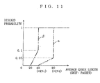
FIG. 11 is a graph representing a packet discard probability
according to RIO. In FIG. 11, curve α represents a discard
probability of in-profile packets Pe, and curve β represents a
discard probability of out-of-profile packets Pe. More
specifically, as represented with curve α, the discard
probability of in-profile packets Pe remains at 0 until the
average queue length of the non-priority queue 220 reaches a
relatively small reference value RVc. After the average queue
length has reached the reference value RVc, the discard
probability continues to rise at a constant rate until the average
queue length reaches a reference value RVd that is greater than
the reference value RVc. Once the average queue length exceeds
the reference value RVd, any additional in-profile packets Pe are
discarded. On the other hand, as shown in FIG. 11, any out-of-profile
packets Pe are discarded at smaller average queue
lengths than the in-profile packets Pe since a higher discard
priority is given to AF22.
Thus, also in this variant packet classification process,
assuming that a traffic of packets Pc assigned with priority
information PI by the home GW 122 has a CBR flow using a UDP, a
traffic of packets Pc assigned with non-priority information NPI
will include a TCP flow, i.e., a flow using a TCP. Any packets
Pc composing the TCP flow are assigned with either AF21 or AF22,
and therefore are added to the non-priority queue 220. Thus,
since the TCP flow is added to the non-priority queue 220, packets
are prevented from arriving at the receiving end in a non-consecutive
order. As a result, as in the case described above,
the packets Pc are forwarded in the proper (consecutive) order.
Furthermore, a combination of the discard control according to
RIO and the TCP flow control ensures that any packet Pe composing
even a TCP flow is protected (i.e., not likely to be discarded)
so long as they are in-profile packets, i. e., packets Pe assigned
with AF21.
FIG. 12 is a block diagram illustrating the structure of
each inter-building GW 15 shown in FIG. 7. In FIG. 12, the
inter-building GW 15 differs from the inter-building GW 5 of FIG.
6 only in that a front end packet classification section 17, an
identifier assigning section 14, and a packet classification
section 16 are provided instead of a front end packet
classification section 225, an identifier assigning section 214,
and a packet classification section 218. Therefore, any
component elements in FIG. 12 that function in similar manners
to their counterparts in FIG. 6 are denoted by like numerals, with
the descriptions thereof omitted. Furthermore, the identifier
assigning section 14 and the packet classification section 16
perform the same processes as their counterparts in the
intra-building GW 13, and therefore descriptions thereof are
omitted.
After receiving a packet Ph from a routing section 26, the
front end packet classification section 17 performs a first packet
classification process. In the first packet classification
process, the packet classification section 17 determines which
one of the identifiers AF11, AF21, AF22, and AF31 has been assigned
to each received packet Ph. After this determination is made,
the front end packet classification section 17 passes any packet
Ph assigned with AF11 to a bandwidth monitoring section 213 as
a priority packet PPh, and passes priority information PI to both
the bandwidth monitoring section 213 and the identifier assigning
section 14 as was the case with the front end packet classification
section 225.
Furthermore, similarly to the front end packet
classification section 225, the front end packet classification
section 17 passes any packet Ph assigned with AF31 to the packet
classification section 16 as out-of-bandwidth packets OPh.
The front end packet classification section 17 differs from
the front end packet classification section 225 in that the front
end packet classification section 17 passes any packet Ph assigned
with either AF21 or AF22 to the bandwidth monitoring section 213
as non-priority packets NPh, and passes non-priority information
NPI to both the bandwidth monitoring section 213 and the
identifier assigning section 14.
As described in the first embodiment, both information
about priority of each received packet and information indicating
whether the packet can be forwarded within the assured bandwidth
or not are mapped onto a DSCP value in the form of identifiers
AF11, AF21, AF22, and AF31, thereby enabling each device on a
network to determine the original priority of each received packet.
Thus, if congestion occurs when packets are outputted from the
inter-building GW 5 to the shared link 8 during communications
from the user-privately-owned network 2 to the external network
7, it is possible to realize priority control using the original
priority of each packet.
(third embodiment)
FIG. 13 is a schematic diagram illustrating an exemplary
structure of a network system 31 for apartment buildings according
to a third embodiment of the present embodiment. In FIG.13, the
network system 31 differs from the network system 1 of FIG. 1 only
in that a user-privately-owned network 32 and a Layer 2 switch
(hereinafter referred to as L2 switch) 33 are provided instead
of a user-privately-owned network 2 and an intra-building GW 3.
Therefore, any component elements in FIG. 13 that function in
similar manners to their counterparts in FIG. 1 are denoted by
like numerals, with the descriptions thereof omitted.
Furthermore, the user-privately-owned networks 32 and 2 differ
from each other in that a home GW 322 is provided in the
user-privately-owned network 32 as opposed to the home GW 22 of
the user-privately-owned network 2, although both have a
plurality of terminals 21 in common.
Next, the components of the network system 31 will be
described in detail. FIG. 14 is a block diagram illustrating the
detailed structure of the home GW 322 shown in FIG. 13. In FIG.
14, the home GW 322 differs from the above described home GW 2
only in that a packet transmitting section 34 is provided instead
of a packet transmitting section 28. Therefore, any component
elements in FIG. 14 that function in similar manners to their
counterparts in FIG. 2 are denoted by like numerals, with the
descriptions thereof omitted.
The packet transmitting section 34 receives a packet Pc from
a transmission control section 27, and assembles an Ethernet frame
as illustrated in FIG. 21 from the received packet Pc in accordance
with IEEE 802. 1Q/p. The assembled Ethernet frame is outputted
as a packet Pn to the interconnection link 4 (which is exemplary
of the "output link" recited in the claims). Note that, although
a packet is generally referred to as a frame in a data link layer,
both the packet and the frame are protocol data units. Thus, in
the present embodiment, "packets" and "frames" are employed with
the same meaning. Furthermore, identifiers AF11 to AF31 assigned
in the transmission control section 27 are the identifiers used
in an IP layer, and therefore it is impossible to use these
identifiers in the data link layer that is lower than the IP layer.
Therefore, the packet transmitting section 34 uses a conversion
table 35 previously stored therein to convert the identifiers AF11
to AF31 uniquely into fifth to seventh priority identifiers,
respectively, which are used in the data link layer (priorities
as defined under IEEE 802. 1p). FIG. 15 is a schematic diagram
illustrating an exemplary structure of the conversion table 35.
The conversion table 35 illustrated in FIG. 15 dictates that AF11
is converted into the fifth priority identifier 0x7; AF21 is
converted into the sixth priority identifier 0x5; and AF31 is
converted into the seventh priority identifier 0x3. The packet
transmitting section 34 assembles an Ethernet frame by setting
one of the aforementioned fifth to seventh priority identifiers
in the priority field as defined under IEEE 802. 1Q/p, and outputs
the Ethernet frame as a packet Pn. The outputted packet Pn is
transferred over the interconnection link 4, and received by the
L2 switch 33.
FIG. 16 is a block diagram illustrating the detailed
structure of the L2 switch 33 shown in FIG. 13. In FIG. 13, the
L2 switch 33 includes a packet transmission apparatus 36, which
comprises a packet receiving section 37, a switching section 38,
a transmission control section 39, and a packet transmitting
section 310.
Referring to FIG. 16, the packet receiving section 37
receives the packet Pn transferred over the interconnection link
4 (which is exemplary of the "first link" recited in the claims),
and passes the received packet Pn to the switching section 38.
The switching section 38 changes a destination IP address (see
FIG. 21) of the packet Pn passed from the packet receiving section
37, and passes the processed packet Pn to the transmission control
section 39 as a packet Pr.
The transmission control section 39 performs transmission
control for each received packet Pr. In order to perform this
transmission control as shown in FIG. 16, the transmission control
section 39 includes a packet classification section 311, a
priority queue 312, a non-priority queue 313, an out-of-bandwidth
queue 314, and a scheduling section 315.
The packet classification section 311 receives the packet
Pr from the switching section 38, and performs the same packet
classification process as that performed by the packet
classification section 218. The packet classification section
311 determines which one of the identifiers 0x7, 0x5, and 0x3 has
been assigned to each received packet Pr. After this determination
is made, the packet classification section 311 adds any packet
assigned with 0x7 to the priority queue 312 as a priority packet
PPr, any packet assigned with 0x5 to the non-priority queue 313
as a non-priority packet NPr, and any packet assigned with 0x3
to the out-of-bandwidth queue 314 as an out-of-bandwidth packet
OPr.
The scheduling section 315 starts operating according
to a predetermined timing, similarly to the scheduling section
222, in accordance with PQ (Priority Queuing) to pass one of a
priority packet PPr, a non-priority packet NPr, and an out-of-bandwidth
packet OPr extracted from the priority queue 312,
the non-priority queue 313, and the out-of-bandwidth queue 314,
respectively, as a packet Ps to the packet transmitting section
310. The scheduling section 315 performs a process which is
similarly derivable from that performed at the scheduling section
222, and therefore the descriptions thereof are omitted.
As described in the first embodiment, with the above
described process, packets PPr and NPr are prevented from
stagnantly staying in the priority queue 312 and the non-priority
queue 313, respectively. As a result, any packets classified as
a priority packet PPb at the home GW 322 are forwarded with a
minimum delay to the receiving end. Furthermore, it is possible
to minimize delay jitter of the priority packets PPb.
The packet transmitting section 310 receives the packet Ps,
and disassembles the received packet Ps in accordance with an IP
into a packet Pg of a format shown in either FIG. 17 or FIG. 18,
and outputs the packet Pg to the shared link 6 (which is exemplary
of the "second link" recited in the claims) . The outputted packet
Pg is transferred over the shared link 6, and received by the
inter-building GW 5.
As described above, according to the present embodiment,
the first to third identifiers in the IP layer are each mapped
onto the fifth to seventh priorities in the data link layer (i.e.,
lower layer). Thus, it is possible to realize priority control
in the data link layer.
In the third embodiment, the packet transmitting section
34 converts AF11, AF21, and AF31 into 0x7, 0x5, and 0x3,
respectively. However, the present invention is not limited to
these three types of priority. Four types of identifiers, i.e.,
AF11, AF21, AF22, and AF31 may be mapped onto four priorities of
the data link layer, or any greater number of identifiers may be
mapped onto a corresponding number of priorities in the data link
layer.
While the invention has been described in detail, the
foregoing description is in all aspects illustrative and not
restrictive. It is understood that numerous other modifications
and variations can be devised without departing from the scope
of the invention.