EP1306663A2 - A method of operating an automatic sample testing machine - Google Patents
A method of operating an automatic sample testing machine Download PDFInfo
- Publication number
- EP1306663A2 EP1306663A2 EP03075139A EP03075139A EP1306663A2 EP 1306663 A2 EP1306663 A2 EP 1306663A2 EP 03075139 A EP03075139 A EP 03075139A EP 03075139 A EP03075139 A EP 03075139A EP 1306663 A2 EP1306663 A2 EP 1306663A2
- Authority
- EP
- European Patent Office
- Prior art keywords
- card
- cards
- station
- sample
- machine
- Prior art date
- Legal status (The legal status is an assumption and is not a legal conclusion. Google has not performed a legal analysis and makes no representation as to the accuracy of the status listed.)
- Granted
Links
Images


Classifications
-
- G—PHYSICS
- G01—MEASURING; TESTING
- G01N—INVESTIGATING OR ANALYSING MATERIALS BY DETERMINING THEIR CHEMICAL OR PHYSICAL PROPERTIES
- G01N21/00—Investigating or analysing materials by the use of optical means, i.e. using sub-millimetre waves, infrared, visible or ultraviolet light
- G01N21/62—Systems in which the material investigated is excited whereby it emits light or causes a change in wavelength of the incident light
- G01N21/63—Systems in which the material investigated is excited whereby it emits light or causes a change in wavelength of the incident light optically excited
- G01N21/64—Fluorescence; Phosphorescence
- G01N21/645—Specially adapted constructive features of fluorimeters
- G01N21/6452—Individual samples arranged in a regular 2D-array, e.g. multiwell plates
-
- G—PHYSICS
- G01—MEASURING; TESTING
- G01N—INVESTIGATING OR ANALYSING MATERIALS BY DETERMINING THEIR CHEMICAL OR PHYSICAL PROPERTIES
- G01N1/00—Sampling; Preparing specimens for investigation
-
- G—PHYSICS
- G01—MEASURING; TESTING
- G01N—INVESTIGATING OR ANALYSING MATERIALS BY DETERMINING THEIR CHEMICAL OR PHYSICAL PROPERTIES
- G01N21/00—Investigating or analysing materials by the use of optical means, i.e. using sub-millimetre waves, infrared, visible or ultraviolet light
- G01N21/01—Arrangements or apparatus for facilitating the optical investigation
- G01N21/13—Moving of cuvettes or solid samples to or from the investigating station
-
- G—PHYSICS
- G01—MEASURING; TESTING
- G01N—INVESTIGATING OR ANALYSING MATERIALS BY DETERMINING THEIR CHEMICAL OR PHYSICAL PROPERTIES
- G01N21/00—Investigating or analysing materials by the use of optical means, i.e. using sub-millimetre waves, infrared, visible or ultraviolet light
- G01N21/17—Systems in which incident light is modified in accordance with the properties of the material investigated
- G01N21/25—Colour; Spectral properties, i.e. comparison of effect of material on the light at two or more different wavelengths or wavelength bands
- G01N21/27—Colour; Spectral properties, i.e. comparison of effect of material on the light at two or more different wavelengths or wavelength bands using photo-electric detection ; circuits for computing concentration
- G01N21/274—Calibration, base line adjustment, drift correction
- G01N21/276—Calibration, base line adjustment, drift correction with alternation of sample and standard in optical path
-
- G—PHYSICS
- G01—MEASURING; TESTING
- G01N—INVESTIGATING OR ANALYSING MATERIALS BY DETERMINING THEIR CHEMICAL OR PHYSICAL PROPERTIES
- G01N21/00—Investigating or analysing materials by the use of optical means, i.e. using sub-millimetre waves, infrared, visible or ultraviolet light
- G01N21/62—Systems in which the material investigated is excited whereby it emits light or causes a change in wavelength of the incident light
- G01N21/63—Systems in which the material investigated is excited whereby it emits light or causes a change in wavelength of the incident light optically excited
- G01N21/64—Fluorescence; Phosphorescence
- G01N21/645—Specially adapted constructive features of fluorimeters
-
- G—PHYSICS
- G01—MEASURING; TESTING
- G01N—INVESTIGATING OR ANALYSING MATERIALS BY DETERMINING THEIR CHEMICAL OR PHYSICAL PROPERTIES
- G01N35/00—Automatic analysis not limited to methods or materials provided for in any single one of groups G01N1/00 - G01N33/00; Handling materials therefor
- G01N35/00029—Automatic analysis not limited to methods or materials provided for in any single one of groups G01N1/00 - G01N33/00; Handling materials therefor provided with flat sample substrates, e.g. slides
- G01N2035/00039—Transport arrangements specific to flat sample substrates, e.g. pusher blade
- G01N2035/00049—Transport arrangements specific to flat sample substrates, e.g. pusher blade for loading/unloading a carousel
-
- G—PHYSICS
- G01—MEASURING; TESTING
- G01N—INVESTIGATING OR ANALYSING MATERIALS BY DETERMINING THEIR CHEMICAL OR PHYSICAL PROPERTIES
- G01N35/00—Automatic analysis not limited to methods or materials provided for in any single one of groups G01N1/00 - G01N33/00; Handling materials therefor
- G01N35/00029—Automatic analysis not limited to methods or materials provided for in any single one of groups G01N1/00 - G01N33/00; Handling materials therefor provided with flat sample substrates, e.g. slides
- G01N2035/00099—Characterised by type of test elements
- G01N2035/00148—Test cards, e.g. Biomerieux or McDonnel multiwell test cards
Landscapes
- Physics & Mathematics (AREA)
- Health & Medical Sciences (AREA)
- Pathology (AREA)
- Life Sciences & Earth Sciences (AREA)
- Chemical & Material Sciences (AREA)
- Analytical Chemistry (AREA)
- Biochemistry (AREA)
- General Health & Medical Sciences (AREA)
- General Physics & Mathematics (AREA)
- Immunology (AREA)
- Nuclear Medicine, Radiotherapy & Molecular Imaging (AREA)
- Engineering & Computer Science (AREA)
- Mathematical Physics (AREA)
- Theoretical Computer Science (AREA)
- Spectroscopy & Molecular Physics (AREA)
- Automatic Analysis And Handling Materials Therefor (AREA)
- Investigating, Analyzing Materials By Fluorescence Or Luminescence (AREA)
- Investigating Or Analysing Materials By Optical Means (AREA)
- Investigating Or Analysing Materials By The Use Of Chemical Reactions (AREA)
- Sampling And Sample Adjustment (AREA)
- Investigating Or Analysing Biological Materials (AREA)
- Apparatus Associated With Microorganisms And Enzymes (AREA)
Abstract
Description
- This invention relates to machines and systems for automatically loading a test sample card having one or more reagent-filled sample wells with fluid samples (e.g., samples containing microbiological agents), and for conducting optical analysis of the samples after reaction with the reagents. The invention is particularly suitable for use in biological, blood or chemical analysis machines, as well as immunochemistry and nucleic acid probe assay machines.
- Biological samples can be reacted and subjected to chemical or optical analysis using various techniques, including transmittance and/or fluorescence optical analysis. The purpose of the analysis may be to identify an unknown biological agent or target in the sample, to determine the concentration of a substance in the sample, or determine whether the biological agent is susceptible to certain antibiotics, as well as the concentration of antibiotics that would be effective in treating an infection caused by the agent.
- A technique has been developed for conducting optical analysis of biological samples that involves the use of a sealed test sample card containing a plurality of small sample wells. Typically, during manufacture of the cards, e.g. for microbiological analysis, the wells are filled with either various types of growth media for various biological agents, or also various concentrations of different antibiotics. The cards have an intemal fluid passageway structure for allowing fluid to enter the wells of the card through a transfer tube port. An L-shaped integral transfer tube extends outwardly from the transfer tube port. The prior art method involved the manual insertion of one end of the transfer tube into the card and the other end into a test tube, and then the manual placement of the card with attached transfer tube and test tube into a vacuum filling sealing machine, such as the Vitek® Filler Sealer. The filling and sealing machine generates a vacuum, causing the fluid in the test tube to be drawn into the wells of the sample card. After the wells of the card are loaded with the sample, the cards are manually inserted into a slot in a sealer module in the machine, where the transfer tube is cut and melted, sealing the interior of the card. The cards are then manually removed from the filler/sealer module and loaded into a reading and incubating machine, such as the VITEK® Reader. The reading and incubating machine incubates the cards at a desired temperature. An optical reader is provided for conducting transmittance testing of the wells of the card. Basically, the cards are stacked in columns in the reading machine, and an optical system moves up and down the column of cards, pulling the cards into the transmittance optics one at a time, reading the cards, and placing the cards back in the column of cards. The VITEK® Reader is described generally in the Charles et al. patent, U.S. No. 4,188,280.
- This arrangement has limitations, in that two machines, a filler/sealer and a reader, are required to process and analyze the cards. Furthermore, additional time and labor are required to conduct the complete analysis of the card.
- Combining the several functions of biological sample processing and optical reading into a single automatic sample processing and reading machine poses substantial challenges. One particularly difficult challenge is to provide a way of conducting the vacuum loading of the cards, and to provide a way for moving the loaded sample card to incubation and optical reading stations. Another challenge is to design a transport, system for moving the sample cards and receptacles about the machine to the various stations.
- The present inventive automated sample testing machine achieves these goals by providing a machine that performs dilution for susceptibility testing, fills the cards with the samples at a vacuum station, and seals the card by cutting the transfer tube, and conducts incubation and optical transmittance and fluorescence analysis of the cards, all automatically. The machine is capable of conducting susceptibility and identification testing of a sample placed in a single test tube in one test run. The machine provides for rapid, automatic identification and susceptibility testing of the sample. In a preferred form of the invention, a number of different test samples are tested in one test run, and moved in a sample tray or "boat" around the machine among the various stations. The tray receives a cassette that contains a plurality of test tubes and associated test sample cards. The machine provides for novel pipetting and diluting stations, permitting fluids to be added to the test tubes or transferred from one test tube to another.
- The machine further has a unique test sample positioning system that moves the tray (with test tubes and cards) about the machine over a base pan. The design of the positioning system is such that it permits essentially a custom configuration of stations above the base pan. Expansion of the machine to include additional carousels and reading stations can be readily accomplished.
- A machine is provided for automatically testing a fluid sample delivered to reagent-filled wells of a test sample card. The machine has a loading station and a sample tray moveable within the machine from the loading station to various stations, where operations are performed on the test sample and the test sample card. The samples are placed in fluid communication with the test sample cards when the samples and cards are loaded into the tray.
- The machine includes a vacuum station having a vacuum chamber moveable relative to the tray between upper and lower positions. When the vacuum chamber is lowered to its lower position, the vacuum chamber cooperates with a peripheral horizontal surface in the tray to make a sealing engagement with the tray. The vacuum station has a vacuum source for supplying vacuum to the chamber and valves for controlling the drawing of vacuum and releasing the vacuum. The fluid samples are loaded in the cards when the vacuum is released from the vacuum chamber.
- In one aspect of the invention, novel vacuum loading techniques are provided for the vacuum station in order to prevent air bubbles from entering the wells of the card. These techniques include maintaining a predetermined rate of change of pressure in the vacuum pressure as vacuum in drawn, and maintaining the vacuum level at a threshold or set point for a short period of time in order to properly fill the card. After the vacuum loading process is completed, the tray is then advanced to a sealing station, where a hot cutting wire is used to cut off the transfer tube for the card and seal the interior of the card from the atmosphere.
- The machine also has an incubation station for incubating the card. A test sample positioning system is provided for moving the tray from the loading station to the vacuum station and from the vacuum station to the incubation station. The cards are unloaded automatically from the tray in to the incubation station. An optical reading station is provided for reading the cards during incubation of the cards in the incubation station. A test sample card transport station is provided for transporting the test sample card from the incubation station to the optical reading station where the optical reading station conducts optical analysis of the sample loaded into the test sample card.
- In a preferred form of the invention, a diluting station is provided for selectively adding diluent to the receptacles or test tubes in the tray. A pipetting station is also provided for transferring fluid samples from one receptacle to another. The diluting and pipetting stations are preferably placed close to each other, so as to permit simultaneous pipetting and diluting operations to be performed on the receptacles in the tray.
- In another aspect of the invention, the sample cards and receptacles are loaded onto a cassette, and the cassette placed in the tray in the machine. A stand-alone information system is provided for associating fluid or test sample and test card information with the cassette. A machine-readable memory storage device is applied to the cassette. A machine-readable indicator is applied to the sample cards and is identified with each of the test sample cards. An information loading station reads the machine-readable indicators for a plurality of the sample cards when they are loaded in the cassette, and stores information regarding the test sample cards onto the machine-readable memory storage device. As the cassette is moved within the automated sample testing machine, it passes by an information retrieving station which retrieves information stored in the machine-readable memory storage device.
- In a preferred embodiment, the information loading station has a memory, a human interface for transferring testing information input from a user of the system into the memory, a reader for the machine readable indicator, and a software program responsive to the human interface for associating in the memory testing information from the user with the machine-readable indicator applied to the test sample card.
- Presently preferred embodiments of the invention are depicted in the drawings, wherein like reference numerals refer to like elements in the various views, and wherein:
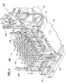
- Figure 1 is a perspective view of a preferred automatic biological sample testing machine in accordance with the invention. The card disposal station and machine cover panels are removed in order to more clearly show the other features of the machine.
- Figure 1A is a block diagram of the all of the principal stations in the machine of Figure 1.
- Figure 2 is a perspective view of the machine of Figure 1, with the diluting and pipetting stations removed to better illustrate the vacuum station of the machine, and with the stacking disposal station included to show its relationship to the sample card transport station and optical systems.
- Figure 3 is an end view of the machine, partially in section, as seen from the right-hand side of the machine looking toward the center mount.
- Figure 4 is a detailed perspective view of the vacuum chamber of the vacuum station of Figure 2 engaging the top surface of the boat, as it would be when the fluid samples are loaded into the cards.
- Figure 5 is a detailed perspective view of the cut and seal station, showing the hot cutting wire cutting through the transfer tubes for the cards when the boat is advanced past the hot cutting wire, thereby sealing the interior of the cards.
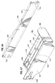
- Figure 6 is a detailed perspective view of the test sample positioning system of Figures 1 and 2.
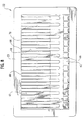
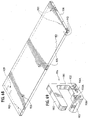
- Figure 7 is a detailed perspective view of the boat and cassette of Figures 1-3.
- Figure 8 is a plan view of the cassette and boat of Figure 7 in an assembled condition.
- Figure 9 is a side view of the cassette and boat of Figure 7.
- Figure 10 is a sectional view of the cassette and boat of Figure 9 along the lines 10-10.
- Figure 11 is a side view of the cassette and boat of Figure 7, as seen from the opposite side of Figure 9, showing the apertures in the cassette that receive touch memory buttons that store information as to the cards carried by the cassette.
- Figure 12 is a bottom plan view of the boat of Figures 1 and 7-11.
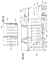
- Figure 13 is a plan view of the base pan of Figure 6.
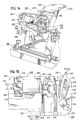
- Figure 14 is a more detailed perspective view of the diluting and pipetting stations of Figure 1.
- Figure 15 is an elevational view of the diluting and pipetting stations of Figure 14.
- Figure 16 is a side view of the diluting station of Figure 15.
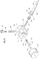
- Figure 17 is an exploded view of the solenoid and shot tube assembly of Figure 14;
- Figure 18 is an isolated view of the diluting station of Figure 14, partially in section, showing the shot tube and thimble valve in greater detail.
- Figure 19 is an isolated, sectional view of the thimble valve of Figure 18.
- Figure 20 is an isolated, sectional view of the shot tube and thimble valve of Figure 18, showing the relationship of the plunger relative to the thimble valve when the valve is in a closed condition relative to the fluid intake port;
- Figure 21 is an isolated, sectional view of the shot tube and thimble valve of Figure 18, showing the relationship of the plunger relative to the thimble valve when the valve is in an open condition relative to the fluid intake port.
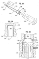
- Figure 22 is an end view of the pipetting hopper system showing the movement of a horizontal slide between two positions, controlling the ability of pipettes to be removed from the housing via a slot in the housing.
- Figure 23 is an exploded view of the pipette hopper system of Figure 22.
- Figure 23A is a more detailed exploded view of the rotatable drum of Figure 23, showing
the couplings that couple the
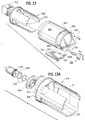
motor 312 to thedrum 340. - Figure 24 is a perspective view of the pipetting hopper system of Figure 1 when the pipette housing is rotated to a pipette fill position, with the cover swung open to permit the housing to be filled with pipettes.
- Figure 25 is an elevational view of the
pipetting station 300 with the tubular tapered transfer pin assembly rotated to fluid withdrawal position where the straw can be lowered into a receptacle. - Figure 26 is a side view of the tubular tapered transfer pin assembly as seen from the
straw hopper 304 in Figure 25. - Figure 27 is a top plan view of the tubular tapered transfer pin assembly along the lines 27-27 of Figure 26.
- Figure 28 is a detailed view, partially in section, of a portion of the pipette hopper system of Figure 25, showing the insertion of the tapered tubular transfer pin into a pipette to make a friction fit with the pipette, permitting the pipette to be removed from the pipette housing.
- Figure 29 is a schematic diagram of the vacuum station of Figure 3.
- Figure 30 is a graph of showing the change in vacuum inside the vacuum chamber of Figure 29 as a function of time during the loading of the cards.
- Figure 31 is an elevational view of a preferred sample card transport system for the machine of Figures 1 and 2.
- Figure 32 is a side view of the sample card transport station of Figure 31, looking in the direction of the carousel and incubation station of Figures 1 and 2.
- Figure 33 is a sectional view of the carnage and slide assembly of Figures 31, which permits the drive subassembly to move relative to the bulkhead.
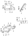
- Figure 34 is a perspective view of a push mechanism that pushes the cards out of the slots in the carousel of FIG. 2 into the sample card transport system of Figure 31.
- Figure 35 is a perspective view of the push mechanism as seen from the rear of the bulkhead.
- Figure 36 is an elevational view of the movement of the card out of the sample card transport station into the stacking disposal station.
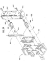
- Figure 37 is a perspective view of the fluorescence optical substation of the optical reading system of Figures 1 and 2, with the reflector assembly in an open position to better illustrate the optical head.
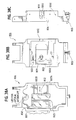
- Figure 38A is a plan view of the front of the reflector assembly of Figure 37.
- Figure 38B is a plan view of the rear of the reflector assembly of Figure 37.
- Figure 38C is a side view of the reflector assembly of Figure 37.
- Figure 39 is an exploded view of the flash lamp cassette of Figure 37.
- Figure 40 is a sectional view of the fluorescence optical substation of Figure 37.
- Figure 40A is a graph of the reflectance as a function of wavelength for the UV cold mirror of Figure 40.
- Figure 40B is a graph of the filter transmittance as a function of wavelength for the 365 nM bandpass filter of Figure 40.
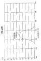
- Figure 41 is a cross section of the solid standard of Figure 40.
- Figure 42 is a graph of the excitation and emission spectra of the solid standard of Figure 40.
- Figure 43 is a front view of the optical head of Figure 37, showing the optical interrupt channel and the six channels for reading six wells of the card.
- Figure 44 is a rear view of the optical head of Figure 37.
- Figure 45A is a top view of the lens assembly holder of Figure 37.
- Figure 45B is a rear view of the lens assembly holder.
- Figure 45C is a side view of the lens assembly holder.
- Figure 45D is an end view of the lens assembly holder.
- Figure 46 is a schematic diagram showing the relationship of the flash lamp of Figure 39 and the optical channels of the optical head of Figure 40.
- Figure 47A is a rear view of the optical interface block of Figure 37, showing the detector board mounted to the optical interface block.
- Figure 47B is a front view of the optical interface block of Figure 47A, showing the placement of the bandpass filters in front of the optical channels.
- Figure 48A is a front view of the detector board of Figure 40, showing the photodiode detectors that are placed behind the six channels of the optical interface block.
- Figure 48B is a rear view of the detector board of Figure 48A.
- Figure 49 is a block diagram of a preferred peak detector board for the fluorescence substation of Figure 37.
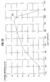
- Figure 50 is a graph of the responsivity as a function of incident radiation wavelength of the photadiode detectors of Figure 48A.
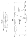
- Figure 51 is a graph of the filter transmittance as a function of wavelength for the 445 nM bandpass filter of Figure 40.
- Figure 52 is a graph of the reflectance (and transmittance) as a function of wavelength for the beam splitter of Figure 40.
- Figure 53 is a detailed elevational view of the transmittance substation of Figure 3.
- Figure 54 is a perspective view of one of the three LED transmittance emission sources of Figure 53.
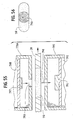
- Figure 55 is a sectional view of the transmittance substation of Figure 53, showing the relationship between the LED transmittance light source, sample well, and photodiode detector.
- Figure 56 is an elevational view of the sample well and LED output for the transmittance substation of Figure 55.
- Figure 57 is an isolated, perspective view of the stacking disposal station of Figure 2.
- Figure 58 is another perspective view of the stacking disposal station of Figure 57, with the
latch and pressure plate removed in order to better illustrate the card slot and snap
element 910A. - Figure 59 is a perspective view of the stacking disposal station of Figures 57 and 58, as seen from below, showing the pair of guide rails along which the pressure plate is slid.
- Figure 60 is another perspective view of the stacking disposal system of Figure 57, as seen from below and the opposite side shown in Figure 57.
- Figure 61 is another perspective view of the stacking disposal system of Figure 60 as seen from below and behind the left or front support plate of Figure 57.
- Figure 62 is a fragmentary, top plan view of the stacking disposal system of Figures 57-61, showing the insertion of a card into the card slot and the push plate pushing the card over the snap elements to join the other cards stacked in the region between the rear surface of the snap elements and the pressure plate.
- Figure 63 is an elevational view of a preferred test sample card for use with the stacking disposal system and overall sample testing machine.
- Figure 64 is an elevational view, partially in section, showing the loading of the cards into
the card slot by the sample
card transport system 700 of Figure 1. - Figure 65 is an isolated, perspective view of the front support of Figure 57.
- Figure 66 is an isolated, perspective view of the bottom vertical support of Figure 61.
- Figure 67 is an isolated, perspective view of the magazine of Figure 60.
- Figure 68 is an isolated, perspective view of the horizontal support of Figure 60.
- Figure 69 is an perspective view of the pressure plate of Figure 57.
- Figure 70 is a side view, partially in section, of the pressure plate of Figure 69.
- Figure 71 is an end view of the pressure plate of Figure 69.
- Figure 72 is an isolated, perspective view of the push plate of Figure 57.
- Figure 73 is a perspective view of the push slide from the push plate drive assembly of Figure 61.
- Figure 74 is a front elevational view of the push slide of Figure 61.
- Figure 75 is a side view of the push slide of Figure74.
- Figure 76 is a perspective view of the push rack of the push plate drive assembly of Figure 61.
- Figure 77 is a perspective view of a stand-alone data input station that loads information
from bar codes placed across the top of the
cards 28 onto a pair of touch memory buttons. - Figure 78 is a illustration of a portion of the center mount and base pan of Figure 1, showing the placement of a touch memory button reading station along the side of the center mount. The two contacts of the reading station touching the two touch memory buttons on the side of the cassette as the boat and cassette are moved past the station.
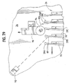
- Figure 79 is a side view of a portion of the cards and cassette as they pass by the card separation device and the bar codes on the cards are red by a bar code reading station.
-
- Figure 1 is a perspective view of a biological
sample testing machine 20 that conducts analysis of test sample filledcards 28 according to a preferred embodiment of the invention. The machine has a set of removable cover panels covering the machine and presenting an aesthetically pleasing appearance and allowing user access to system components that are not shown in order to better illustrate the functional aspects of the machine. In Figure 1, a stacking card disposal station for thecards 28 has been removed in order to illustrate the other components of the machine. Thecard disposal station 900 is shown in Figure 2. Figure 3 is an end view of the machine, partially in section, showing the position of thetest sample cards 28 as they are processed in several of the stations in themachine 20. Figure 1A is a block diagram of themachine 20 as a whole, showing the layout of the stations and the path of a boat and cassette assembly and test sample cards through the machine in a preferred embodiment of the invention. - Referring now primarily to Figures 1, 1A and 3, the biological
sample testing machine 20 includes a biological testsample positioning system 100, consisting of four independent motor-driven paddles, which pulls a sample tray 22 (referred to herein as a "boat") incorporating acassette 26 across abase pan 24 around themachine 20 to several discrete stations, where various operations are performed on the cards and receptacles in thecassette 26. Prior to the start of the procedure, a technician loads acassette 26 with a plurality oftest cards 28 and receptacles such astest tubes 30 containing biological or control samples to be tested. Eachtest card 28 has an L-shapedtransfer tube 32 protruding therefrom for permitting the fluids containing biological samples to be drawn from thetest tubes 30 into the reagent-filled wells of thetest cards 28. The technician places the loadedcassette 26 into theboat 22 at a loading station for the machine, such as the front, right hand comer of thebase pan 24 shown in Figure 1. The combinedboat 22 and loadedcassette 26 are then moved as a unit over the surface of thebase pan 24 about themachine 20 by the testsample positioning system 100. - In a typical microbiological testing scenario, described below for purposes of illustration but not limitation, the
test cards 28 come in two varieties: (1) identification cards, in which particular different growth media are placed in each of the wells of thecard 28 when the cards are manufactured, and (2) susceptibility cards, in which different concentrations of different antibiotics are also placed in each of the wells of thecard 28. The identification cards are used to identify the particular unknown biological agent, i.e., microorganism, present in the sample. The susceptibility cards are used to determine the susceptibility of the biological agent to various concentrations of antibiotics or other drugs. In the test procedure described below, identification and susceptibility tests can be performed on a single sample in one cycle of operation of the machine 20 (i.e., one test run). To accomplish this, thecassette 26 is loaded such that atest tube 30A containing a biological sample, connected via atransfer tube 32 to anidentification card 28A, is placed adjacent to anempty test tube 30B connected via atransfer tube 32 to asusceptibility card 28B. - The
cards 28 preferably contain bar codes as well as other identifying indicia on the card for reading by a bar code reader built into themachine 20. The bar codes are unique to each card, and identify card information such as card type, expiration date, and serial number, and are used to correlate test data and/or results from the cards with the patient and the biological sample. In addition, the entire boat or cassette may have sample information for all of the cards loaded in the cassette stored on one or more memory devices affixed to thecassette 26, such as a memory button or "touch button" available from Dallas Semiconductor Corp., 4401 S. Beltwood Parkway, Dallas Texas. - In the representative example shown in Figure 1, seven or eight of the
test tubes 30 in theboat 22 contain biological samples, and are in fluid communication withidentification cards 28A by the straw-like transfer tube 32. The biologicalsample test tube 30A and its associatedidentification card 28A can be thought of as a set. The biological sample test tubes and identification cards are typically arranged in an alternating pattern in thecassette 26. Each biologicalsample test tube 30A andidentification card 28A set is adjacent to anempty test tube 30B placed in communication with a susceptibility card 288 via atransfer tube 32. It will be appreciated that the cards and associated test tubes could be ordered in any order in thecassette 26 depending on the particular testing requirements for the samples. For example, the cards could be arranged as follows: identification (ID), susceptibility (SU), ID, ID, ID, SU, SU, ID, SU .... Further examples would be all identification cards and all susceptibility cards. - The test
sample positioning system 100 operates to move theboat 22 andcassette 26 over thebase pan 24 first to a dilutingstation 200. The diluting station contains arotating shot tube 202, by which a predetermined volume of diluent (such as saline solution) is added to the empty susceptibility test tubes in thecassette 26,e.g. test tube 30B. Other types of fluids may be added to the test tubes by a rotating shot tube, such as reagents, thus dilutingstation 200 is not limited to just adding a diluent to the test tubes. As the leading edge of theboat 22 is moved to the left during this process, it passes under apipetting station 300. Thepipetting station 300 includes a mechanism that automatically removes apipette 302 from a source ofpipettes 304, lowers thepipette 302 into the biologicalsample test tube 30A, and removes with vacuum a predetermined volume of biological fluid from the biologicalsample test tube 30A using thepipette 302. - The test
sample positioning system 100 then moves theboat 22 to the left by an amount equal to the separation distance betweenadjacent test tubes pipetting station 300 then lowers thepipette 302 containing the biological fluid from the biologicalsample test tube 30A into the adjacentsusceptibility test tube 30B (having already received a quantity of diluent from the diluting station 200), expels the fluid into thetest tube 30B, and drops thepipette 302 into thesusceptibility test tube 308. The process of movement of theboat 22 by the testsample positioning system 100, adding diluent to thesusceptibility test tubes 30B at the dilutingstation 200, and transferring of biological samples from the biologicalsample test tubes 30A to the adjacentsusceptibility test tubes 30B at thepipetting station 300, continues until all of the identification and/or susceptibility test tubes sets (if any) in theboat 22 have been so processed. By virtue of the close spacing of thepipetting station 300 and the dilutingstation 200, simultaneous diluting and pipetting operations can be performed on multiple test tubes in asingle boat 22. After the last pipetting operation has been performed, the testsample positioning system 100 then moves theboat 22 all the way to the left-hand edge of thebase pan 24. - It will be understood by persons skilled in the art that the
cassette 26 may be loaded entirely with biological samples in thetest tubes 30 andidentification cards 28, such as the case where a batch of biological samples are to be tested to identify the contents of the samples. In this example, the diluting and pipetting operations are not necessary. However, in other types of sample testing, other diluents or reagents or fluids may be added to or withdrawn from the test tubes. In the example of where no diluting or pipetting operations are performed (e.g., where the pipetting and diluting operations were performed off-line), thecassette 26 is loaded with test tubes and cards, and thepositioning system 100 would simply move theboat 22 and loadedcassette 26 directly past the dilutingstation 200 and thepipetting station 300 without stopping, all the way to the left hand edge of thebase pan 24. - Once at the left hand edge of the
base pan 24, the testsample positioning system 100 operates to move theboat 22 along the left hand edge to avacuum station 400. Thevacuum station 400 is seen better in Figure 2, which is a perspective view of themachine 20 with the dilutingstation 200 and thepipetting station 300 removed, and in Figures 4, 5 and 29. At thevacuum station 400, avacuum chamber 402 is lowered onto theboat 22 such that the bottom surface of thevacuum chamber 402 sealingly engages the topperipheral surface 23 of theboat 22. The vacuum chamber hashoses 406, 408 (Figure 4) that are in communication with a conventional vacuum source for the machine (not shown in Figure 4). Vacuum is applied to thechamber 402 under microprocessor control, causing air in the interior of thetest sample cards 28 to evacuate out of their associated test tubes and to be withdrawn from thechamber 402. The vacuum cycle is precisely managed to optimize filling by using a closed loop servo system to regulate the rate of change of vacuum and the timing of the complete vacuum cycle. After a predetermined period, thechamber 402 is vented to atmosphere under microprocessor control. The venting of the cards causes the fluid in thetest tubes 30 to be drawn into thecards 28, filling the wells in thecards 28. After thechamber 402 is vented, the chamber is raised up by a vacuumchamber drive mechanism 410 so as to permit the boat to be moved to the other stations of themachine 20. - The test
sample positioning system 100 then operates to advance theboat 22 to the right across the rear of thebase pan 24 to a cut andseal station 500, located behind thecenter mount 34 in Figures 1 and 2. Referring to Figures 4 and 5, the cut andseal station 500 consists of ahot cutting wire 506 and attachedsupport plate 504, and a drive mechanism 502 (e.g., stepper motor, drive belt and lead screw) that lowers the cutting wire andsupport plate 504 to the same elevation as the top portion of thetransfer tubes 32 adjacent to where thetransfer tubes 32 enter thetest cards 28. As theboat 22 is advanced past the cut andseal station 500, thetransfer tubes 32 are forced past thehot cutting wire 506. By virtue of the assistance of fore and aft constraints placed on the movement of thecards 28 by the walls of thecassette 26, and the lateral constraints on the movement of thecard 28 by the cassette and wall structures of themachine 20, the hot cutting wire cuts thetransfer tubes 32 by melting of the transfer tube material as theboat 22 is slowly advanced past thehot cutting wire 506. A small stub of transfer tube material is left on the exterior of thecard 28. The stub seals the interior of thecard 28 from the atmosphere (except, in certain types of cards, for possible diffusion of gasses such as oxygen through oxygen permeable tape covering the sample wells). When the boat is advanced past thestation 500, thewire 506 is raised up to its upper position. - Referring to Figures 1 and 3, the test
sample positioning system 100 then advances theboat 22 across the rear of thebase pan 24 behind thecenter mount 34 to acarousel incubation station 600. A reciprocating rack andpinion driver 610 is mounted to thecenter mount 34 opposite aslot 602 in the machine that pushes the cards off thecassette 26 one at a time through theslot 602 into acarousel 604. Thecarousel 604 is housed in an enclosure that is maintained at an appropriate incubation temperature. The enclosure is partially broken away in Figures 1 and 2 in order to show thecarousel 604. Thecarousel 604 is rotated by adrive system 612 in synchronism with the movement of theboat 22 over the rear of thebase pan 24 by the testsample positioning system 100, so as to place the next slot in thecarousel 604 in line with theslot 602 opposite the next card in thecassette 26. If the carousel is only going to be partially loaded with cards, the operating system of the machine may control thecarousel 604 rotation to load the cards into non-adjacent slots to equally distribute the cards in the carousel in order to balance out the weight distribution in thecarousel 604. For example, where the carousel has 60 slots and only 30 cards are to be processed, the cards could be loaded into every other slot. - Additional incubation capacity required for processing a larger number of cards at one time can be provided by adding an additional incubation station(s) to the rear of the basepan, and adjusting the dimension of the base pan and drive system components as necessary. Additional optics stations may be provided for additional carousels. For example, if the
carousel 604 has sixty slots and each cassette holds 15 cards, four boats can be processed at once. If a second carousel is added, up to 120 cards could be processed at once. Of course, different capacities could be provided for thecassette 26 and thecarousel 604. - After all of the
cards 28 have been loaded into the slots of thecarousel 604, theboat 22 is advanced along the right hand edge of thebase pan 24 back to its starting position (shown in Figures 1 and 2) or to an exit position for removal of the cassette 26 (containing the test tubes, pipettes 302, if any, and transfer tubes remnants) and receipt of a new cassette. Alternatively, theboat 22 could be moved to an exit station located, for example, in the rear or right hand side of thebase pan 24. - As the
cards 28 are being incubated in theincubation station 600, the cards are periodically, sequentially pushed out of the slots of thecarousel 604 at the top of thecarousel 604, one at a time, by a reciprocating rack andpinion driver 620 and an associated stepper motor. Thecards 28 are moved by an optical scannercard transport station 700 past a fluorescence andtransmittance optics station 800 having atransmittance substation 802 and afluorescence substation 804. The wells of thecard 28 are selectively subject to sets of transmittance and/or fluorescence optical testing according to the analysis needed to be performed by the transmittance andfluorescence optics station 800. The transmittance andfluorescence optics station 800 includes detectors and processing circuitry to generate transmittance and fluorescence data for the wells in thecards 28, and to report the data to a central processing unit for themachine 20. If the test is not complete, thetransport station 700 moves thecard 28 back into its slot in thecarousel 604 for more incubation and additional reading. - Typically, each card will be read every 15 minutes as the carousel makes one revolution. Typical incubation times for the
cards 28 are on the order of two to eighteen hours, consisting of roughly four transmittance and/or fluorescence data sets per hour, each data set consisting of multiple readings, for each of the wells in thecard 28 subject to the optical analysis requirements. - After the testing is complete, the cards are moved by the optical
scanner transport system 700 into acard output station 900 shown in Figure 2 and Figure 3. Thecard output station 900 consists of a detachable tray ormagazine 902 and associated support structure that is positioned to the side of theoptical station 800 at approximately the same elevation as theoptical station 800. Thestation 900 has apressure slide 914 that is moveable within themagazine 902 and a constant force spring biasing the pressure slide towards the front of the magazine. The cards are stacked in the magazine between thepressure slide 914 and oppositely opposed resilient snap elements integrally formed in the sides of themagazine 902. The technician removes themagazine 902 from themachine 20 as needed or when the magazine is full of cards, empties the cards into a suitable biohazard disposal unit, and replaces themagazine 902 back into themachine 20. - An automated microbiological testing system or
machine 20 for testing fluids containing microbiological samples contained inopen receptacles 30 is thus described. Thesystem 20 is for use in conjunction withtest sample cards 28 having a plurality of sample wells, the test sample cards comprising susceptibility cards and identification cards. The system comprises a base pan, atray 22 for carrying thereceptacles 30 and test cards across thebase pan 24, a dilutingstation 200 for adding a predetermined volume of fluid to at least one of saidreceptacles 30, and apipetting station 300 for transferring test samples from one of the receptacles in thetray 22 to another of thereceptacles 30B in thetray 22. Avacuum station tray 22 and cooperating with the peripheral edge of thetray 23 to form a vacuum enclosure around thereceptacles 30 andcards 28. The vacuum station further comprises a vacuum source for loading the fluid samples into the wells of thecards 28. A sealingstation 500 is provided for sealing the cards after loading of thecards 28. Anincubation station 600 is provided for incubating thecards 28, and areading system cards 28. Apositioning system 100 moves thetray 22 over thebase pan 24 from thevacuum station 400 to theincubation station 600 and has adriver 610 loading the cards from thetray 22 into theincubation station 600. Adrive system 700 is proved for moving the cards from theincubation station 700 to the readingstation - The automated
sample testing machine 20 thus performs a method for conducting identification and susceptibility testing of a biological agent in a fluid sample, the fluid sample containing the biological agent is placed in a first open receptacle ortest tube 30A. The method comprises the steps of: - placing the
first receptacle 30A in a sample holder orcassette 26 with the fluid sample placed in fluid communication via the L-shaped transfer tube with an identificationtest sample card 28A received by saidsample holder 26; - placing a second
open receptacle 30B in thesample holder 26, the secondopen receptacle 30B in fluid communication with a susceptibility test sample card 288 received by thesample holder 26; - placing the
sample holder 26 with the first andsecond receptacles test sample cards sample testing machine 20; - thereafter, within said machine,
- adding a predetermined volume of diluent to the
second receptacle 30B (via the diluting station 200); - transferring a portion of the fluid sample from the
first receptacle 30A to thesecond receptacle 30B (via the pipetting station 300); - loading the identification and susceptibility cards with fluids from the first and
second receptacles vacuum station 400; and subsequently - conducting optical analysis at
stations 802 and/or 804 of the identification andsusceptibility cards -
- It is of significant advantage in the above method that the steps of adding a predetermined volume of a diluent to the
receptacle 30B, transferring a portion of the fluid fromreceptacle 30A toreceptacle 30B, vacuum loading and conducting optical analysis of the identification and susceptibility cards are performed automatically within the automatedsample testing machine 30 without any human intervention. - In the preferred embodiment of the invention, the
boat 22 is not rotated during its cycle of movement around the machine, and hence the general orientation of theboat 22 is unchanged. Since the boat is moved along four sides of a rectangle in the preferred embodiment, theboat 22 is preferably given a rectangular shape with four sides, each side having a complimentary surface for engaging one of the fourpaddles 38A-D in the drive system 100 (see Figure 6). - The
boat 22 andcassette 26 are shown in several views in Figures 7-12. The boat and cassette are separate units in the preferred embodiment, with theboat 22 typically remaining in themachine 20 after processing of the cards in the cassette 26 (except for removal for cleaning). Thecassette 26 is loaded withcards 28 andtest tubes 30 off line, and, following data entry functions described later, the loaded cassette is placed in theboat 22 in themachine 20 by a technician at the start of the entire processing procedure. In an alternative embodiment, the boat and cassette could be an integral unitary sample holder that is removed from themachine 20 for loading with cards and test tubes, and placed into the loading station of the machine for subsequent processing. - Referring to Figures 7-12, the
boat 22 has apaddle engaging surface 60A which is slanted at an angle relative to theside wall 81 of theboat 22. Thisplanar surface 60A is engaged with a complimentary planar angled surface of the head of thepaddle 38A as the paddle slides the boat over the front side of thebase pan 24. A second angled engaging surface 60AA is provided, which allows thepaddle 38A (Figure 6) to engage a second surface on theboat 22. This second engaging surface 60AA reduces the collar travel on theshaft 42A needed to move theboat 22 to the extreme front left comer of thebase pan 24. Thepaddle 38A may be rotated out of engagement withsurface 60A, moved down theshaft 42A to a position adjacent to surface 60AA, and rotated back into engagement with surface 60AA. - The right hand side of the
boat 22 has asurface 60D that is engaged by the paddle 38D when the paddle 38D moves the boat along the right hand side of thebase pan 24. Similar engaging surfaces are provided on the rear and left hand sides of theboat 22. - The
cassette 26 has a plurality ofslots 61 for sample cards 28 (Figure 1), each of which is adjacent to a testtube holding slot 62 securely retaining a test tube. Atang 64 or other suitable resilient member extends inwardly in the testtube holding slot 62 and prevents the test tubes from moving in theslot 62. Thecard slots 61 are separated from each other by awall 70. Theslots 61 are given a dimension so as to permit a slight amount of fore and aft movement of the sample cards betweenadjacent walls 70. Thewalls 70 extend only about a third of the way up thecards 28, permitting fore and aft rocking motion of the cards by the separation device 94 (see Figures 3, 79), allowing a bar code reader to read bar codes placed at the top of the cards. - The
cards 28 rest on thefloor 66 of theslots 61. Anopen side 68 in the slots permits the cards to be slid out of thecassette 26 into the incubation station 600 (Figure 1). - Referring to Figure 7, the
boat 22 has aflat floor 74 which contains any spills from the test tubes. Thefloor 74 is given a shape so as to snugly receive thecassette 26 when thecassette 26 is loaded into theboat 22. - The
boat 22 has a substantially flat topplanar surface 23 that is supported by a plurality of reinforcingribs 76 along the sides and bottom of theboat 22. Thesurface 23 sealingly engages the bottom surface of the vacuum chamber 402 (Figure 2). Theribs 76 help theboat 22 bear the compressive forces placed on the peripheral sealingsurface 23 of theboat 22 by thechamber 402. - Referring to Figure 11, a pair of
apertures 78 are provided in the rear of thecassette 26 which receive touch memory storage buttons (not shown). The touch buttons identify the contents of thecards 28 loaded into thecassette 26. This information is then read bytouch button readers 85 mounted to thecenter mount 34 of the machine 20 (see Figure 3). Preferably, a stand-alone cassette identification station is provided for themachine 20. The station has a computer terminal and touch button contacts. The contacts load information as to the cards for the cassette into two touch buttons placed in thetouch button apertures 78. - Referring now in particular to Figures 6 and 13, the test
sample positioning system 100 will be described in detail. Thesystem 100 is shown in a perspective view in Figure 6 with all of the stations mounted to thecenter mount 34 and theincubation station 600 removed in order to more clearly illustrate the components of thepositioning system 100. - The
system 100 has abase pan 24 mounted to atable support structure 18, across which theboat 22 is pulled from station to station in themachine 22. Thebase pan 24 in the preferred embodiment is of rectangular shape having four sides at right angles to each other: a front side, a left hand side (LHS), a rear side, and a right hand side (RHS). The four sides allow theboat 22 to be moved clockwise in a loop about the machine back to its starting position at a loading station (shown in Figures 1-2) after all of the operations on thesample card 28 have been completed. However, the inventive principles of the test sample positioning system are applicable to other geometries for abase pan 24. Additionally, the paddles and motors are capable of moving theboat 22 in a counter-clockwise direction. - The
boat 22 has four downwardly depending feet 72 (Figures 9 and 10) at its four corners which fit in a pattern of tracksections comprising grooves 36 formed between a set of raisedridges 37 and a raisedrim 39 extending around the perimeter of thebase pan 24. Thegrooves 36 help prevent any rotation of theboat 22 as theboat 22 is pulled over thebase pan 24. - When the
boat 22 is initially located at the loading station, as shown in Figure 13, the left front LF and right front RF feet of theboat 22 are positioned ingroove 36A, the right rear (RR)foot 72 is ingroove 36D, with the RF foot at the intersection ofgrooves slots 35 are provided in the raisedridges 37 so as to permit the feet of theboat 22 to move through theridges 36 as theboat 22 is moved about thebase pan 24. For example, slot 35D permits the right rear RR foot to move past raised ridge 37D, and slot 35B permits the left rear LR foot to move past the ridge 378 into thegroove 36B. Thecenter mount 34 has acomer 33 that is preferably given a sharp contour, as shown, so as to prevent the boat from undergoing rotation as it is slid along the left hand side of the base pan. - In order to move the
boat 22 clockwise about the base pan, four independent drive systems are provided for moving theboat 22. Each drive system moves theboat 22 in one direction along one of the four sides of thebase pan 24. Referring now in particular to Figure 6, a first drive system is provided for moving theboat 22 along the front edge of thebase pan 24, and consists of arotatable shaft 42A having a square cross section, acollar 40A slideably mounted on theshaft 42A, adrive belt 44A mounted to the collar for sliding thecollar 40A along theshaft 42A, astepper drive motor 48A driving abelt 50A, apulley 52A for moving thedrive belt 44A back and forth along the front edge of the base pan, and asecond pulley 46A for thedrive belt 44A. Apaddle 38A is mounted to thecollar 40A, and is provided for engaging one or more complimentary surfaces (e.g. surface 60A) on the side of theboat 22. When thedrive motor 48A is operative to move thebelt 44A such that thecollar 40A is moved to the left along theshaft 42A, thepaddle 38A pulls theboat 22 to the left across thebase pan 24. - A shaft rotate
motor 54A is also provided with an associated belt and pulley (not shown) for rotation of theshaft 42A by an angle of 90 degrees. When the shaft rotatemotor 54A rotates theshaft 42A such that the head of thepaddle 38A is in a horizontal position in the direction of theboat 22, thepaddle 38A is in a position to engage a complimentary surface on the side of theboat 22 so as to pull theboat 22 as thepaddle 38A andcollar 40A are moved along theshaft 42A. When the boat has reached the end of its travel along the front edge of thebase pan 24, the shaft rotate motor 54 rotates theshaft 42Apaddle 38A is rotated upwards and away from the side of theboat 22, thereby disengaging thepaddle 38A from theboat 22. - Each of the other three drive systems in the
sample positioning system 100 is functionally equivalent to the drive system described above for the front edge of thebase pan 24, and each is composed of like components. For example, the left hand side LHS drive system has ashaft 42B,collar 40B with attachedpaddle 38B,drive belt motor 48B,shaft rotation motor 54B etc. Like components for the rear edge of the base pan include arotatable shaft 42C,belt drive motor 48C, etc. Similarly, right hand side (RHS) drive system has a rotatable shaft 42D,collar 40D and attached paddle 38D, etc. - The diluting
station 200 of Figure 1 is shown in more detail in Figures 14-16. Figure 14 is a perspective view of the diluting andpipetting stations station 200. - Referring to Figures 14-16, the diluting
station 200 can be thought of as a system for dispensing a controlled volume of fluid into a receptacle such as a test tube. Thestation 200 has a source ofdiluent fluid 204, such as a flexible bag of saline solution, that rests on a suitableinclined shelf 203. Arotating shot tube 202 having a predetermined volume receives the fluid from thesource 204 via a conduit ortube 206. Afilter 208 is placed in theconduit 206, and serves to prevent contaminants from entering theline 206. - A
solenoid 220 is provided for controlling the opening of a thimble valve placed within theopen end 201 of theshot tube 202. The thimble valve controls the flow of the fluid from theconduit 206 into theshot tube 202. Since the source offluids 204 is placed above theshot tube 202, the fluid fills theshot tube 202 by gravity flow. theshot tube 202 is mounted to thesolenoid 220 housing. Thesolenoid 220 and attached shot tube rotates relative to thebulkhead 214 by means of a motor 219 (Figure 16) having a drive belt and pulley (not shown). Themotor 219 is placed directly behind thesolenoid 202 on the back side of thebulkhead 214. - When the
shot tube 202 is rotated to a generally upward orientation (i.e., the tip of the shot tube is elevated with respect to theend 201 of the shot tube), such as that shown in Figures 14-16, the shot tube can be filled with fluid such that the shot tube is automatically primed as it is filled. The upward orientation of theshot tube 202 permits air within the shot tube to be eliminated from theshot tube 202 as the fluid enters theend 201 of the shot tube and works its way up to the tip of theshot tube 202. Anoptical sensor 218 mounted to abracket 216 is provided for detecting when the diluent fills the shot tube up to the fill zone adjacent to the tip of theshot tube 202. - When the shot tube is filled, the
motor 219 behind thebulkhead 214 rotates thesolenoid 220 and shottube 202 in the direction of the arrow 222 (Figure 15) to a second position, wherein the tip portion of theshot tube 202 is oriented downward towards a test tube in the boat 22 (Figure 1). Asecond conduit 210 is provided which is in communication with a source ofcompressed air 217 mounted behind thebulkhead 214. Afilter 212 is provided in theconduit 210, and prevents contaminants from entering theline 210. Theconduit 210 is fitted over an exhaust tube in theshot tube 202 in the vicinity of the thimble valve. When theshot tube 202 is in the second downward position, compressed air is injected into the shot tube in a stream to exhaust the diluent from theshot tube 202 into the test tube 308 (Figure 1). - Referring now to Figure 17, the
solenoid 220 and shottube 202 are shown in an exploded view. Thesolenoid 220, when energized, actuates acam slide 256 placed within theaperture 225 along thesolenoid axis 221. Thesolenoid 220 has acam spring 258 that biases thecam slide 236 to a valve closed position, towards the left in Figure 17. A rubber 0-ring 223 seats onto thehead 253 of thecam slide 256. Thecam slide 256 has acam surface 258 which cooperates with acam surface 259 on aplunger 224 so as to translate cam slide motion alongaxis 221 intoorthogonal plunger 224 motion along the shot tube axis S. Theplunger 224 is moved into and out of engagement with thethimble valve 226 as described below, and opens thevalve 226 when the plunger is moved to an extended position by thecam slide 256. This arrangement permits the solenoid to be mounted at a right angle to theshot tube 202, decreasing the amount of space between the pipetting and diluting stations and enabling simultaneous pipetting and diluting operations to performed on different test tubes in the boat. - The solenoid assembly of Figure 17 further includes a shot tube opening 266 that receives the
shot tube 202 andthimble valve 226 when theshot tube 202 is in an assembled condition. Theshot tube 202 has anexhaust tube 230 connected to theexhaust conduit 210 and afill tube 228 connected to thediluent conduit 206. Arelease pin 260, aspring 262 and arelease pin cap 264 are provided to permit the user to engage and disengage theshot tube 202 and thimble valve from the rest of the assembly, such as when the user replaces thesaline bag 204 and shottube 202. Therelease pin 260 mounts to the top of thehousing 221 through an aperture and recessedregion 261 in thehousing 221. When therelease pin cap 264 is rotated, thespring 262 lifts therelease pin 264 out of engagement with theend 201 of theshot tube 202, permitting theshot tube 202 to be removed from thehousing 221. - Referring now to Figure 18, the
shot tube 202,solenoid 220 andoptical sensor 218 are shown isolated from themachine 20, with theshot tube 202 andthimble valve 226 shown in section. Thesolenoid 220 includes avalve plunger 224 that is disposed within the interior of thethimble valve 226. Referring to Figure 19, thethimble valve 226 is shown isolated in a sectional view. Thethimble valve 226 is a thimble-shaped member made of a resilient material such as silicone. Thevalve 226 has awall portion 244 and afront sealing rib 240 that sealingly engages the interior of the shot tube in a compression fit to seal off thefill tube 228 connected to thesource 204 of diluent. Thethimble valve 226 has anannular body portion 242 that defines rear sealingribs 248 that fit into complementary recessed regions in the interior of theshot tube 202 adjacent to theend 201 of theshot tube 202, and constrain thethimble valve 226 in theopen end 201 of theshot tube 202. Thebody portion 242 defines acentral chamber 246 for receiving theplunger 224. - Figure 20 shows the position of the
plunger 224,thimble valve 226, filltube 228 and shottube 202 when thethimble valve 226 is in a closed condition. Thefront sealing rib 240 seals off thefill tube 228, preventing fluid from entering the interior region orchamber 254 of theshot tube 202. Figure 21 shows the position of theplunger 224 andthimble valve 226 when theplunger 224 is pushed by thesolenoid 220 against thewall 244 to an extended position. Theplunger 224 pushes against thewall 244 to extend and stretch thethimble valve 226 in a manner to cause thefront sealing rib 240 to move away from the interior surface of theshot tube 202 towards the interior 254 of theshot tube 202, permitting fluid to flow from thefill tube port 250 around and past therib 240 into theinterior 254 of theshot tube 202. - Referring to Figures 18-21, when the
tube 202 is filled with diluent up to the shot tubeoptical sensor zone 232, theplunger 224 retracts to the position shown in Figure 20, shutting off the flow of fluid. Preferably, the opticalsensor fill zone 232 is given a tapered shape as shown so as to define a small volume for the diluent, permitting filling of the shot tube with precision. The tapered opticalsensor fill zone 232 and resulting small volume allows only a very small volume of fluid to travel beyond theoptical sensor 218 during the closing of thethimble valve 336. Theshot tube 202 is then rotated to a downward vertical position above the susceptibility test tube, whereupon compressed air is supplied viaconduit 210 andexhaust tube 230 to anexhaust port 252 and into the interior of theshot tube 202. The stream of compressed air forces the fluid in the interior region out thetip 234 of theshot tube 202. - From Figures 20-21, it can be seen that in its relaxed, normal position, the
thimble valve 226 is closed. The retraction of theplunger 224 from thewall 244 of thethimble valve 226 to close the valve helps prevent any pressure surges or "water hammer" effect to be generated in the filled shottube 202, as would be the case if the thimble valve were to be designed to be pushed to an extended position to close theport 250. If pressure surges were to cause diluent to eject out of thetip 234 of theshot tube 202, contamination of the shot tube could potentially result. Hence, a design of athimble valve 226 that is retracted to close the valve, preventing pressure surges, is a preferred design. - In a preferred form of the invention, the
saline bag 204,conduit 206 and shottube 202 are combined and installed in themachine 20 as a replaceable, disposable fluid delivery unit. When thesaline bag 204 is empty, the user simply replaces thesaline bag 204, shot tube 202 (including thimble valve 226) andconduit 206 as a single unit, avoiding any problems with contamination or disinfection of theshot tube 202. Theconduit 210 may or may not be part of the fluid delivery unit, and, if not, it would fit over theexhaust tube 230 when theshot tube 202 andsaline bag 204 are mounted in themachine 22. - Referring again to Figures 14-16, in a preferred embodiment the
solenoid 220 is oriented relative to theshot tube 202 in a manner to save space and allow theshot tube 202 andsolenoid 220 to be placed as close as possible to thepipetting station 300. The axis of the shot tube is perpendicular to the axis ofmovement 221 of the solenoid (into the page in Figure 15). Thecam slide 256 in thesolenoid 220 translates motion in the direction of the axis 221 (Figure 16) into plunger motion in the direction of the thimble valve and shottube 202 along the axis S of theshot tube 202. This is shown in Figure 17. - Thus, a
system 200 for dispensing a controlled volume of fluid into a receptacle such as a test tube has been described, comprising a source of said fluid (such as a diluent stored in a flexible bag 204), ashot tube 202 comprising atip portion 230, a hollow body, and a fluid entrance port, and aconduit 206 for conducting said fluid from saidsource 204 to the fluid port of theshot tube 202. Amotor 219 rotates the shot tube from a first or fill position,
wherein the tip portion of theshot tube 202 is oriented at an incline above horizontal relative to the hollow body during filling of the shot tube, to a second or dispensing position, wherein the tip portion is oriented downward towards the receptacle during dispensing of the fluid. A valve controls the flow of the fluid into the hollow body of theshot tube 202. By virtue of the above arrangements, air within theshot tube 202 may be eliminated from the shot tube through theelevated tip portion 230 during the filling of the shot tube, resulting in an effective priming of the shot tube and a loading of the shot tube with a precise amount of the fluid. - The
pipetting station 300 is shown in Figures 14 and 15 in an overall aspect. Thestation 300 includes apipette hopper 304 and dispensing assembly shown in an end view in Figure 22 and an exploded view in Figure 13. - Referring to Figures 14, 15 and 22-24 in particular, the
station 300 includes a generally cylindrical housing orhopper 304 that contains a plurality ofhollow pipette straws 320. As seen in Figure 22, thehousing 304 has a horizontally disposed strawwithdrawal opening slot 350 at the bottom of thehousing 304. Thehousing 304 is mounted to ablock 306 which is rotatable relative to abulkhead 310 by apin 308 secured to thebulkhead 310, so as to permit thehousing 304 to rotate upwards from the orientation shown in Figure 1 to the orientation shown in Figure 24. The housing includes aclear plastic cover 305 which prevents thestraws 320 from falling out of thehousing 304. Theplastic cover 305 is mounted to thehousing 304 via ascrew 303 and a mounting hole 307 (Figure 23) in thehousing 304. As shown in Figure 24, theplastic cover 305 swings out from a position covering thehousing 304 opening so as to permit a technician to refill thehousing 304 withstraws 320. - When the
housing 304 is in the normal, horizontal position in Figures 1 and 22, theslot 350 is positioned immediately above ahorizontal slide member 314. Referring to Figure 22, thehorizontal slide 314 has asolenoid 336 that is mounted to the back side of thebulkhead 310 for moving the slide between extended and retracted positions. Thesolenoid 336 could be mounted to the front of the bulkhead in a different configuration if desired. The movement of theslide 314 is accomplished by moving ashaft 338 that theslide 314 is mounted to back and forth. Theslide 314 is slid along guides 337. - A stepping motor 312 (Figures 15 and 23) mounted to the rear wall of the
drum 340 is provided to sweep arotatable drum 340 having three equidistantly spacedfingers 342 about the interior surface of thehousing 304. In a preferred embodiment, each of thefingers 340 define a sweep angle α of approximately 60 degrees. As best seen in Figure 22, as thefingers 342 sweep along the interior surface of thehousing 304, one of the fingers sweeps astraw 320 in thehousing 304 into theslot 350. Thefingers 342 stop their movement such that a portion of thefinger 342 covers theslot 350, with a straw positioned below the finger in the slot, as shown in Figure 22. When thehorizontal slide 314 is in the position 314' shown in dashed lines in Figure 22, thetop surface 354 of theend portion 356 of theslide 314 is positioned below theslot 350 in contact with abottom housing surface 352, preventing astraw 320 from falling out of thehousing 304 through theslot 350. As shown best in Figure 22, the sides of theslot 350, thefinger 342 and theslide 314 all cooperate to firmly retain thestraw 320 in the slot, permitting the taperedtubular transfer pin 330 to be inserted into the end of thestraw 320. - Referring to Figure 22, the
housing 304 is made from a low friction material. Preferably, thehousing 304 is constructed such that the inside diameter of thehousing 304 is less than the length of the housing, so as to maintain thestraws 320 in a condition oriented parallel to the length of thehousing 304, so that they can be readily swept into theslot 350. - Referring now in particular to Figure 23A, the
drum 340 is shown in greater detail. Adrive lug 348 is rotated by themotor 312 of Figure 23. Thedrive lug 348 has pair ofcircumferential recesses 348. A pair of drive 0-rings 346 fit over therecesses 349. Thedrive lug 348 fits into agrip sleeve 344 by means of a set of three inwardly projectingpoints 345, which securely grip the 0-rings 346. Thegrip sleeve 344 in tum is securely mounted to thecentral aperture 341 in the rear wall of thedrum 340. When thelug 348 is rotated by themotor 312, thedrum 340 is rotated about the motor and drum axis M. The grip sleeve and 0-ring construction of Figure 23A reduces noise and vibration. - While the
slide 314 is in the extended position 314' and the straw is trapped in theslot 350 as shown in Figure 22, a tapered tubular transfer pin 330 (Figures 15, 23) is moved from a retracted position in atransfer pin assembly 316 into an extended position directly into thestraw 320 in theslot 350, so as to frictionally engage the tip of thestraw 320. At this point, thehorizontal slide 314 retracts towards thebulkhead 310. Thetransfer pin 330 now is rotated by a motor 360 (Figures 24-26) to a vertical position as shown in Figure 1, permitting thestraw 320 to be moved through theslot 350 out of thehousing 304. As soon as thestraw 320 is rotated out of theslot 350, theslide 314 is moved back to the position 314' shown in dashed lines in Figure 22, and themotor 312 is operated to sweep anotherstraw 320 into theslot 350. - The tapered
tubular transfer pin 330 with attachedstraw 302, now in a vertical orientation directly above one of the test tubes in thecassette 26, is lowered so that the end of the straw 302 (Figure 1) is immersed sufficiently into the fluid in one of the test tubes (e.g. test tube 30A), such as a test tube containing a biological or control fluid sample. Vacuum is applied to thetubular transfer pin 330 and attachedstraw 302 for a predetermined period of time, drawing a precise and controlled volume of fluid into thestraw 302. Thetubular transfer pin 330 and attached straw (with fluid) is raised up so as to clear the top of the test tube. The boat and test tube are advanced by thepositioning system 100 by an amount equal to the separation distance of adjacent test tubes. Thetubular transfer pin 330 andstraw 302 are lowered into thesusceptibility test tube 30B, whereupon the vacuum applied to thetransfer pin 330 is released, causing the fluid contents of thestraw 302 to fall into thesusceptibility test tube 30B. At this point, thetubular transfer pin 330 is moved to a position wholly within the tubular transfer pin housing so as to eject thestraw 302, dropping the straw into the susceptibility test tube. Thetransfer pin assembly 316 is then raised back to the elevation of thehopper 304, rotated into a horizontal position, and the process repeats. - Referring to Figures 25-27, the
transfer pin assembly 316 and associated motor and vacuum system for thetransfer pin 330 are illustrated in greater detail. Referring to Figure 25 in particular, amotor 322 is mounted behind the bulkhead and includes adrive belt 324 that turns apulley 326 and a threadedshaft 362, referred to in the art as an ACME thread or lead screw. Atransfer pin plate 361 is mounted to the threaded shaft via a pair ofcollars 364. Depending on the direction that themotor 322 rotates theshaft 362, theplate 361 and attachedtransfer pin assembly 316 is slid either up or down the twopillars 359 between an upper position, in which thetransfer pin 330 is at the same elevation as thestraw withdrawal slot 350 in thehousing 304, and a lower position in which thestraw 302 is in a position to withdraw fluid from a receptacle placed below thetransfer pin assembly 316. - A
second motor 360 having adrive belt 363 andpulley 365 is mounted to the rear of thetransfer pin plate 361, and is provided for rotation of the entiretransfer pin assembly 316 in the direction of the arrow of Figure 25 between a first position, in which thetransfer pin 330 is oriented in the direction of thestraw withdrawal slot 350, to a second position, in which thestraw 302 is oriented vertically downward in the position shown in Figures 1 and 25. - Referring to Figure 26, the
transfer pin assembly 316 is illustrated in a side view as seen from thepipette housing 304. The transfer pin assembly has atransfer pin housing 331 which defines atransfer pin aperture 368. The tapered tubular transfer pin 330 (Figure 27) reciprocates between a retracted position in the housing (shown in Figures 26 and 27), and an extended position shown in Figure 25 at which it engages a straw in thestraw withdrawal slot 350 as shown in Figure 28. A transferpin actuation solenoid 370 is mounted to the rear of thetransfer pin assembly 316 to move the tubulartapered transfer pin 330 between the retracted and extended positions. A source ofvacuum 366 is mounted adjacent to thetransfer pin housing 331, and provides vacuum to the end of thetransfer pin 330 via atube 372. A vacuum pressure transducer P is provided which monitors the vacuum generated by thesource 366 to ensure that a straw is attached to the taperedtubular transfer pin 330, that fluid is withdrawn into the straw, and that a sufficient volume of liquid is transferred. This pressure transducer P is positioned at the end of asecondary vacuum line 373 in communication with the vacuum source. A suitable pressure transducer P is the Motorola model MPX 5010D sensor. - When the
transfer pin 330 andstraw 302 are rotated from a horizontal position to the vertical position shown in Figure 25, thestraw 302 is rotated out of theslot 350 in thehousing 304. Themotor 322 then operates to lower thetransfer pin assembly 316 to the appropriate level such that thestraw 302 is immersed in thetest tube 30A. After withdrawal of the fluid from thetest tube 30A, themotor 322 raises thetransfer pin assembly 316 up such thatstraw 302 clears the top of thetest tube 30A, and then lowers theassembly 316 intotest tube 30B aftertest tube 30B is placed below thestraw 302. To remove thestraw 302, thetransfer tube 330 is retracted into thetransfer tube housing 331. The diameter of thestraw 302 is slightly larger than the diameter of thetransfer pin aperture 368, forcing thestraw 302 off of thetransfer pin 330 as thetransfer pin 330 with completely withdrawn into thetransfer pin housing 331 in the position shown in Figure 27. In this embodiment, thestraw 302 falls intotest tube 30B. The transfer pin assembly is then rotated back into a horizontal position and raised to the level of thestraw withdrawal slot 350 in thehousing 304, and the process is repeated for the next set of test tubes. - From the above description, it will be appreciated that there has been described a method of automatically dispensing straws comprising the steps of placing the straws in a
cylindrical housing 304 having an interior surface, the cylindrical housing defining astraw withdrawal slot 350 therein, sweeping the straws around the periphery of the interior region of the housing and sweeping a straw into thestraw withdrawal slot 350, placing an obstruction (e.g., the horizontal slide 314) in front of thestraw withdrawal slot 350 during a time period in which the straw is not to be removed from thecylindrical housing 350, and removing theobstruction 314 from in front of thestraw removal slot 350 during a time period in which a straw is to be removed from said cylindrical housing. The transfer pin engages the straw when it is retained in thestraw withdrawal slot 350 by theobstruction 314, and rotates the straw out of theslot 350 into a position for pipetting when theobstruction 314 has bee removed from the slot. It will be appreciated that an alternative to the rotational removal of the straw from the slot may be accomplished by a linear retracting motion of the transfer pin. - There has also been described a system for removing liquid from a
receptacle 30, comprising ahousing 304 containing a plurality of hollow straws and defining a straw withdrawal opening 350, a tapered,tubular transfer pin 330 having a tip portion, a source of vacuum connected to said transfer pin, and a drive mechanism for saidtransfer pin 330. The drive mechanism comprises asolenoid 370 means for moving the transfer pin along a first axis towards and away from the straw withdrawal opening 350, the tip portion of thepin 330 engaging a straw disposed in the straw withdrawal opening 350 when thetransfer pin 330 is moved towards the straw withdrawal opening 330, ameans 360 for rotating the transfer pin and straw in an assembled condition to a vertical orientation above thereceptacle 30; and ameans 322 for lowering the transfer pin and straw such that the straw is placed into contact with the liquid in the receptacle and for raising the transfer pin so as to withdraw fluid from thereceptacle 330 when vacuum is applied to thetransfer pin 330. - At the
vacuum station 400 of Figure 1, the vacuum loading of thecards 28 with fluid samples from the test tubes takes place. The vacuum created in thevacuum chamber 402 is controlled in a manner to prevent the formation of bubbles in the wells of thecards 28. Such bubbles can interfere in the accuracy of the reading of the wells by the optical stations. The preferredvacuum loading station 400 is shown schematically in Figure 29. - The
vacuum filing station 400 consists of the following components: - A vacuum pump 420 (Gast PIN: SAA-V110-NB, 115 VAC, 50/60 Hz, 29.5 inch Hg max. Vacuum: 1.75 cfm open flow).
- A proportional vacuum control valve 422 (Honeywell/Skinner P/N: BP2EV0006, 12-24 VDC, 0-5 VDC Control. 0.078 inch diameter orifice).
- A 4-way direct acting solenoid valve 424 (Humphrey P/N: 420, 24 VDC, 60 scfm @ 1100 PSIG inlet pressure, 24 VDC, .250 inch diameter orifice).
- An air filter 426 (Norgren P/N: F39-222EOTA, 4 scfm @ 100 PSIG inlet pressure, 0.01 micron filtration).
- An absolute pressure transducer 428 (Dara Instruments P/N: XCA415AN, Range: 0-15 PSIA, 5 VDC Excitation, 0.25-4.25 V F.S.O., +/-0.5% of F.S.O. Combined Linearity & Hysteresis, +/-0.3% of F.S.O. Repeatability).
- A standard sample preparation node (SPN) printed
circuit board 430. -
Vacuum tubing 432, 0.250 inch inside diameter. - The
drive system 410 for thestation 400 includes a steppingmotor 438 and associatedbelts 440 and threadedshafts 442 that raise and lower thevacuum chamber 402. Anoptical encoder 434 and optical interrupt 436 sense when thevacuum chamber 402 is at its upper and lower positions, respectively. - When the
vacuum pump 420 is turned on, it pulls free air through the filter/muffler 444 attached to the 4-way solenoid valve 424. To fill thecard 28 in theboat 22, the following sequence occurs: Thevacuum chamber 402 is lowered onto theboat 22 with thesample cards 28. The proportional andvacuum control valve 422 is opened 100%. The 4-way solenoid valve 424 is energized and air is pumped out of thevacuum chamber 402 through theair filter 426 and the 4-way solenoid valve 424. Theabsolute pressure transducer 428 gauges thevacuum chamber 402 pressure decrease and sends a proportional continuously changing voltage output to theSPN Board 430. The continuously changing voltage is sampled by theSPN Board 430 at regular intervals and the rate of change is compared to the programmed rate to pump down the vacuum chamber. - If the rate of change is too fast, the
proportional valve 422 is sent a higher control voltage to open wider, if possible, and increase the size of the air leak into thevacuum line 406. If the rate of changes is too slow, theproportional valve 422 is sent a lower control voltage to close down, if possible, and decrease the size of the air leak into thevacuum line 406. The control of the rate of change of pressure insures that vacuum is not drawn too quickly, which can cause splashing and bubbles in thetest tubes 30. This can cause air bubbles to enter thecard 28 when the chamber is vented, interfering with the optical analysis of the card. - The
absolute pressure transducer 428 continues to gauge thevacuum chamber 402 pressure and send the proportional pressure voltage to theSPN Board 430 while the 4-way solenoid valve 424 is de-energized. Thevacuum pump 420 is turned off, and theproportional valve 422 is closed completely for five seconds when the vacuum target (or set point) pressure of 0.90 PSIA is reached. This is to prevent the possibility of the pressure in the vacuum chamber from varying up and down enough to allow sample fluid to be transported in and out of thetest card 28 during the five second dwell period. - The
absolute pressure transducer 428 continues to gauge thevacuum chamber 402 pressure and send the proportional pressure voltage to theSPN board 430, while theproportional valve 422 is opened gradually at the end of the five second vacuum dwell period until the programmed pressure increase rate of change is achieved. - The continuously changing voltage from the
pressure transducer 428 is sampled by theSPN Board 430 at regular intervals and the rate of change to return to atmospheric pressure is compared to the predetermined programmed rate. If the rate of change is too fast, theproportional valve 422 is sent a lower control voltage to close down, if possible, and decrease the size of the air leak into thevacuum line 406. If the rate of change is too slow, theproportional valve 422 is sent a higher control voltage to open wider, if possible, and increase the size of the air leak into thevacuum line 406. This steady controlled venting permits fluid samples to be drawn into thesample cards 28 in a manner to reduce the risk of bubbles forming in the wells of thecard 28, and to insure complete filling of thecard 28. - The
proportional valve 422 is opened 100% at the complete return to atmospheric pressure and held open while thevacuum chamber 402 is raised from theboat 22. This is to prevent a residual vacuum from occurring in thechamber 402 and lifting theboat 22 within thechamber 402. The proportion valve is closed and the system is ready to repeat the cycle. - The vacuum generation, dwell, and venting cycle is illustrated in graphical form in Figure 30. Note the linear draw down
curve 450 of about -0.54 ± 0.07 PSIA per second, the 5second dwell period 452 at 0.90 PSIA, and the linearvent rate curve 454 of about + 0.45 ± 0.07 PSIA per second. - For the illustrated embodiment, it is assumed the relative pressure between the
test card 28 and the surrounding atmospheric media inside thevacuum chamber 402 to be 0 PSI. In reality, there should be a very small pressure difference inside thetest card 28 versus outside thetest card 28 in the vacuum chamber throughout the filling cycle. If, however, one considers the pressure changes inside versus outside the vacuum chamber, then the following cycle information applies to the illustrated embodiment: Initial: local atmospheric pressure (varies with local barometric pressure). Start filling cycle: -.53 +/-0.07 PSI/sec (23-30 seconds pump down). Vacuum dwell: Approx. 5 seconds. Return to atmospheric pressure: +.53 +/-0.07 PSI/sec (23-30 seconds return). A return to atmospheric rates faster than this can causes some test card fills to be incomplete. End: Local Atmospheric Pressure (same as initial). - Thus, a method is for loading a test sample card with a fluid sample, comprising the steps of placing the
test sample card 28 in fluid communication with said fluid sample in thetest tube 30, placing thetest sample card 28 and fluid sample in thetest tube 30 within avacuum chamber 402, and lowering the pressure in thevacuum chamber 402 at a substantially constant and predetermined rate to a set point vacuum level, the rate (e.g., as shown in Figure 30) selected so as to not cause air bubbles to form in the fluid sample as air is removed from the card during the vacuum level. The vacuum is maintained at the set point level for a predetermined length of time (as shown in Figure 30), and released at a predetermined rate in a manner so as to avoid air bubbles from forming in the fluid sample in the card. - The steps of lowering, maintaining and releasing said vacuum are performed in a
vacuum station 400 of the automated sample testing machine, the machine having asample tray 22 moveable within the machine from a loading station (e.g., at the front, right comer of the base pan) to saidvacuum station 400. - The
vacuum station 400 has avacuum control valve 422 in communication with thevacuum chamber 402 operative to insure that the rate of lowering the pressure in the vacuum chamber occurs at the predetermined rate, such as shown in Figure 30. - In another aspect, a
vacuum loading system 400 fortest sample cards 28 placed in fluid communication with a fluid test sample stored in anopen receptacle 30 has been described, comprising avacuum chamber 402 in communication with a source of vacuum, the chamber having a lower peripheral sealing surface at the bottom periphery of thechamber 402, atray 22 for containing thecards 28 and fluid test samples in thetest tubes 30 and having aperipheral surface 23 for sealingly engaging the lower peripheral sealing surface of thevacuum chamber 402, and apositioning system 100 for moving thetray 22 from a loading station to thevacuum chamber 402. Adrive system 410 or means for raising and lowering thevacuum chamber 402 is provided so as to permit thetray 22 to be moved underneath thechamber 402, and to permit thetray 22 to be moved from thevacuum chamber 402 to theincubation station 600. When thechamber 402 is in the lower position its lower edge engages theperipheral surface 23 of thetray 22, enabling vacuum to be generated within thechamber 402. - Once the card is filled with sample in the
vacuum chamber 402, thecassette 26 is moved through a transfer tube cutting and sealingstation 500, best seen in Figures 1, 4, and 5. A formednichrome wire 506 is heated to a precise temperature for cutting through thetransfer tubes 30 using a microprocessor-controlled constant current source (not shown). - The
cassette 26 is moved past thehot wire 506 at a slow speed to allow the wire to cut and seal thetransfer tubes 30 close to thecard 28, forming an external transfer stub. The remainder of thetransfer tube 30 remnant is left in the test tube for disposal, as shown in the extreme right hand side of theboat 22 in Figure 5. - The
hot cutting wire 506 is mounted to amechanism including plates 504 that are raised and lowered by a stepper motor/pulley/drive belt drive assembly 502 (Figure 1), allowing thewire 506 to be moved out of the way to allow un-cut transfer tubes to be moved past the cutting and sealingstation 500. This function can be used to batch load multiple cassettes or for error recovery purposes. - The cutting and sealing
station 500, in cooperation with the testsample positioning system 100, enables multiple transfer tubes to be cut essentially at once as theboat 22 is advanced past thehot cutting wire 506. Control of the cutting of thetransfer tube 32 to produce a reliable seal is accomplished by using a constant current source to control the heat output of thehot cutting wire 506, and controlling the speed at which theboat 22 andcassette 26 is moved past thewire 506. Since the electrical properties of thewire 506 are predetermined, and by holding the current constant and controlling the speed at which the wire passes through the plastic transfer tube 30 (i.e., the speed ofmotor 48C), thestation 500 can simply and precisely control the cutting and sealing of thetransfer tube 32. This heat control design is very simple and does not need temperature calibration. Thewire 506 heats up very quickly, so the wire does not have to be left on all the time. This feature offers safety and energy conservation advantages. - In the prior art cutting and sealing station of the Vitek® sealer, a block of metal is provided with a cartridge heater embedded with a thermocouple connected to a conventional temperature control. This is a fairly expensive, bulky device that needs calibration, cuts only one straw at a time, and requires a long, constantly "ON" heating time. In contrast, the present inventive sealing
station 500 is much smaller, more reliable, and less expensive to manufacture. Rather than controlling temperature, as in the prior art, thestation 500 controls the power with a constant current source applied to the cutting/sealing wire 506 to control heat. Heat is a function of the square of the current since power (P) = I2R. Typically, the setting for the constant current source is set at the factory once and would not have to be adjusted in the field after installation in the field.. - After the
cards 28 have been loaded with sample and sealed, they are inserted into thecarousel 600 and incubated. Periodically, the cards are removed from the slots in the carousel and moved to optical reading stations for reading and returned to the carousel or sent to a stacking disposal system. The mechanism responsible for moving the cards between the carousel and the optical station and stacking disposal system is the samplecard transport station 700, shown in Figure 1 and in greater detail in Figure 31. - Referring now to Figure 31, the sample
card transport station 700 for the optical scanners is shown in an elevational view. Thestation 700 includes adrive assembly 702 having acover plate 704 which is mounted to a bulkhead orsupport 706. Theoptical reader system 800 in the preferred embodiment consists of atransmittance substation 802 and afluorescence substation 804 mounted to thebulkhead 706, the outlines of which are shown in Figure 31. Thesample card 28 is moved from the top of thecarousel 604 by thedrive assembly 702 through theoptical reader system 800 and back to thecarousel 604 if thecard 28 needs further incubation and additional reading. If the card has been sufficiently incubated (based on the analysis of data from the optical reader system 800), thecard 28 is moved to a card reject tray 902 (Figures 2 and 3) to the left of theoptical system 800. - The
drive assembly 702 consists of astepper motor 708, shown in dashed lines, positioned behind a mountingbracket 709. Themotor 708 drives a timingpulley 711 that moves an endless, substantially inelastic,drive belt 710 having teeth 710' over a series ofrollers 712. Thebelt 710 is supported at the top of thecover plate 704 by a set ofrollers 712. The path of the belt through the rollers. 712 is shown in dashed lines in Figure 31. It can be seen that thebelt 710 passes across the top of thecover plate 704 and beneath the optics in theoptical substations drive belt 710 engages the bottom edge of thecard 28 along the top of thecover plate 704. Asuitable drive belt 710 can be obtained from the Gates Rubber Co., of Denver, Colorado, U.S.A. - A
ledge 718 mounted to thebulkhead 706 is provided above thebelt 710 and theoptical reading system 800. The ledge has aslot 720 which receives the upper edge of thecard 28. Theledge 718 andslot 720 defines a card travel direction. When thecard 28 is pushed out of thecarousel 604, thecard 28 is snugly positioned in the space between theslot 720 and thebelt 710. Theentire drive assembly 702, includingcover plate 704,stepper motor 708 anddrive belt 710, is movable relative to thesupport bulkhead 706. To permit the relative movement, a set of carriage andslide assemblies 716 are provided, one of which is shown in more detail in Figure 33. As seen in Figure 33, each carriage andslide assembly 716 includes aslide 730 mounted to thebulkhead 706 by abolt 734. Thecarriage 726 is mounted to thecover plate 704 by a set of fourscrews 724. Thecarriage 726 slides relative to theslide member 730 by means ofball bearings 728 which slide along agroove 732. In the preferred embodiment, two of the carriage andslide assemblies 716 are provided, one on each side of thecover plate 704. - The
entire drive assembly 702 is biased upwards towards theledge 718 by biasingsprings 714. The springs have atop end 713 engaging a pin mounted to thebulkhead 706, and abottom end 715 engaging a pin mounted to thecover plate 704. Threesprings 714 in all are preferred, and are placed at the center and sides of thecover plate 704. Thesprings 714 each have a spring constant K of 16.5 lbs/in., for a total of 49.5 lbs/in for the three springs. The purpose of thesprings 714 is to constantly maintain the proper upward pressure on thecard 28 by thebelt 710, such as in the case of some tolerance variation in the height of the cards. Thedrive belt 710 must provide enough upward force so as to permit the belt to engage the bottom of thecard 28 and move the card along theslot 720, but not too much to cause binding by the drive motor or too little force, which would cause the belt to slip relative to the bottom of the card. By maintaining the proper upward force on the card, such that belt travel is directly translated into card travel, precise movement by thestepper motor 708 results is precise movement of thecard 28 relative to theoptical system 800. This precise movement is discussed in greater detail in conjunction with the operation of thetransmittance substation 802. - Referring to Figure 32, the
drive assembly 702 andbulkhead 706 are shown in a side view, looking towards thecarousel 604 andincubation station 600 of Figure 1. Therollers 712 at the top of thecover plate 704 form a slot, as shown, which helps support the bottom edge of thecard 28. Thecard 28 is snugly positioned between thebelt 710 and theslot 720 in theledge 718. The upward force on thecard 28 by thesprings 714 causes thebelt 710 to grip the bottom edge of thecard 28, such that thecard 28 is slid along theledge 718 by thedrive belt 710 without any significant slippage between thebelt 710 and thecard 28. To facilitate the sliding motion, theslot 720 is made from a low friction material such as Delrin or given a low friction coating. The bottom edge of thecard 28 can be provided with a knurled texture surface such as parallel raised ridges to better enable thebelt 710 to grip thecard 28 as thebelt 710 moves backward and forwards over therollers 712. - Referring to Figures 34 and 35, in order to place the card into the sample
card transport system 700, apush mechanism 648 is provided to push thecard 28 out of thecarousel 604. Figure 34 is a perspective view of thecarousel 604 showing thepush mechanism 648 mounted to the front of thecarousel bulkhead 652, and Figure 35 shows themechanism 648 as seen from the rear of thebulkhead 652. Thepush mechanism 648 includes analignment block 654 mounted to thebulkhead 652 and adriver 656 that reciprocates back and forth relative to theblock 654. Amotor 648 having agear 662 is mounted behind thebulkhead 652. The teeth of thegear 662 cooperate with a set ofteeth 658 on thedriver 656, such that rotation of thegear 662 backwards and forwards causes thedriver 658 to move in the direction shown by the arrow 664 (Figure 35) in the space between alower slot 666 and an upper slot 668 in theblock 654. The end of thedriver 656 is positioned in alignment with thetop slot 614 in thecarousel 604. When thedriver 656 is operated by themotor 648 such that thedriver 656 is pushed into theslot 614, thecard 28 within theslot 614 is pushed out of the slot into the space between theledge 718 and thedrive belt 710. (The construction and operation of the reciprocating cam mechanism that loads thecards 28 into the carousel from thecassette 26 is essentially the same as that for the push mechanism 648). An optical detector 650 (Figure 34) is provided directly above theslot 614 so as to control the rotation of thecarousel 604 such thatslot 614 is properly positioned adjacent thedriver 656 andledge 718. - The
push assembly 648 slides thecard 28 out of theslot 614 at the top of thecarousel 604 and places thecard 28 at the extreme right hand edge of thedrive assembly 702 adjacent to the extreme upperright drive roller 712A. Thestepper motor 708 is operated in a forward direction (rotating the timing pulling 711 in a counter-clockwise direction), causing thedrive belt 710 to move to the left and move thecard 28 to the left towards thetransmittance substation 802. - When the leading edge of the
card 28 reaches thetransmittance substation 802, an optical interrupt LED in the transmittance substation transmits radiation through an optical interrupt aperture 112 (Figure 31) at the base of thecard 28. An optical interrupt detector senses the radiation and sends a signal to the control system to cause themotor 708 to stop. When themotor 708 stops, the first column ofwells 110 in thecard 28 are positioned directly opposite a set of eight transmittance LEDs in thetransmittance substation 802, which conduct transmittance testing of the column of wells in thecard 28. - After an initial illumination of the LEDs, the
motor 708 is operated to rapidly move thebelt 710 in a series of small steps, such that the transmittance optics illuminates the individual wells at a series of positions across the width of the wells. This precise movement of thecards 28 achieves a large set of data for thewells 110. The transmittance testing at multiple positions across thewells 110 will likely include a detection of any air pockets or debris in the wells, enabling the data processing system to detect and possibly reject an abnormal transmittance measurement. - Where fluorescence testing is called for, after all of the wells of the
card 28 have been subject to the transmittance testing bytransmittance substation 802, themotor 708 andbelt 710 slides thecard 28 to thefluorescence substation 804, wherein fluorescence testing of thewells 110 takes place. - Depending on the test status, the
card 28 is then either returned to thecarousel 604 by moving themotor 708 andbelt 710 in the reverse direction, or else themotor 708 andbelt 710 are operated to move the card all the way to the left hand edge of thedrive assembly 702 to place thecard 28 in thecard disposal mechanism 900. - Thus, a method has been described for transporting a
sample card 28 having first and second (top and bottom) edges from aincubation station 600 to areading station 800 in asample testing machine 20, comprising the steps of: - placing the
sample card 28 in a snug space defined by (1) aslot 719 in aledge 718, theslot 719 receiving said top edge of the card and defining a card travel direction, and (2) adrive belt 710 positioned parallel to theslot 719 and supporting the bottom edge of thecard 28; - biasing (with the springs 714) the
drive belt 710 towards ledge so as to maintain pressure between the drive belt, card and slot; - moving the drive belt in the card travel direction so as to slide the card through the
slot 719 to theoptical station 800 without substantial slippage of thecard 28 relative to thebelt 710, thereby permitting precise movement of the card relative to the optical system due to the belt's precise movement by the timingpulley 711 andstepper motor 708. -
- Referring now to Figures 2, 3, 31 and 36, the
card disposal mechanism 900 has atray 902 in which the cards are stacked as they exit the samplecard transport system 700. Theledge 718 is provided with aslant portion 719 at the extreme left-hand end of theledge 718. When thecard 28 is moved past the end of thecover plate 704 onto thetray 902, the upperright hand shoulder 114 of thecard 28 is placed into contact with theslant portion 719. Thetray 902 is slightly lower than the elevation of thebelt 710 at the top of thecover plate 704, assisting the placement of theupper shoulder 114 against theslant 719. A resultant force F (Figure 36) is imparted to thecard 28 by thedrive belt 710 andslant portion 719, causing thecard 28 to snap out of thedrive assembly 702 into thecard reject tray 902. - Referring now to Figure 37, the
fluorescence optics substation 804 is shown in a perspective view isolated from themachine 20. Thesubstation 804 includes aselective reflector assembly 806 mounted via ahinge 808 to anoptical head 810. Theoptical head 810 has a plurality ofsurface apertures 812 defining six optical channels between a fluorescence illumination source and the middle six wells in a column ofwells 100 in thecard 28. The placement and number of the optical channels depends on the lamp size (or number) and the geometry of the sample wells in thecard 28. The illumination source is placed within aflashlamp cassette 816. An LED and detector cooperate with the optical interruptaperture 112 along the base of thecard 28 to precisely position the card in the space between the front surface apertures and the reflector assembly. - When the
hinge 808 is in a closed condition, theselective reflector assembly 806 is positioned parallel to theapertures 812. Thecard 28 is moved back and forth in the space defined by thefront surface apertures 812 and thereflector assembly 806. - The
selective reflector assembly 806 has astepper motor 801 which moves anoptical shuttle 803 back and forth. Areflector 852 and asolid reference 850 are mounted to theoptical shuttle 803. The purpose of the reflector and solid reference are described in more detail below. - Referring to Figure 38A, the front of the
selective reflector assembly 806 is shown isolated from the rest of thestation 804 in a plan view. Theoptical shuttle 803 travels back and forth along a pair ofguides shuttle 803 is in a position such that thereflector 852 is placed directly opposite theapertures 812 of theoptical head 810. Whenever a calibration of the detectors in theoptical head 810 is performed, themotor 801 moves theshuttle 803 such that thesolid reference 850 is placed in the optical path opposite theapertures 812. The selective reflector assembly housing includes a housing for an LED for the optical interruptaperture 112 for thecard 28. Aspring clamp 805 is provided to secure the selective reflector assembly to thehead 110 when theassembly 806 is in a closed condition. - Figure 38B shows the rear of the
selective reflector assembly 806. Theselective reflector assembly 806 is shown in a side view in Figure 38C. Behind theshuttle 803, awell 1000 is provided for a shaft (not shown) from thestepper motor 801. The stepper motor shaft passes through thegap 1002 in the well and is secured to apiece 809 extending upwardly from the rear surface of theoptical shuttle 803. A cover plate (not shown) covers the well 1000 by mounting to the screw holes 1001. The back and forth motion of the shaft of thestepper motor 801 causes theshuttle 803 to slide back and forth along theguides - Referring again to Figure 37, the removeable
flash lamp cassette 816 holds an elongate xenon linear flash lamp, which serves as a fluorescence illumination source for the fluorophores placed in thewells 110 of thecard 28. Theflash lamp cassette 816 is connected to a highvoltage power supply 820. Theflashlamp 824 has a high current capacity connection allowing field replacement of the lamp. This is unique for this lamp type due to the high pulse currents generated during the flash (over 350 amps). - A
peak detector 814 and electronics module is mounted behind theoptical head 810. Theflash lamp cassette 816 includes ainterface block 854 and alamp holder 856 which are shown in further detail in Figure 39. - Referring now to Figure 40, the
fluorescence optics substation 804 is shown in a sectional view perpendicular to the axis of theflash lamp 824 and the six photodiode detectors. Theflash lamp cassette 816 houses thexenon lamp 824, which is mounted at the focus of an elongate cylindrical parabolic reflectingmirror 822. The flash lamp radiation R is reflected off of acold mirror 826 onto a 365nM filter 828, which filters the radiation R to pass radiation at the excitation wavelength of the fluorophores. Filter specifications for thecold mirror 826 and thefilter 828 are shown in Figures 40A and 40B, respectively. After passing through thefilter 828, the radiation R reflects off adichromatic beam splitter 830 along itsoptical path 833 and out of theapertures 812 and into thecard wells 110. Any radiation passing through thewells 110 is reflected off thereflector 852 in theselective reflector assembly 806 and reflected back into thewells 110. The radiation excites the fluorophores in the well 110, causing the fluorophore to briefly to emit radiation. The emission radiation is shown as a dashed line in Figure 40. The emission radiation passes through thedichromatic beam splitter 830, through a focusinglens 836 andband pass filter 838 onto aphotodiode detector 840. There are six photodiode detectors in all for the six optical channels. - The use of a
selective reflector 852 enhances the signal-to-noise ratio and minimizes optical cross-talk by doubling the optical path. Further, when thecard 28 is positioned for reading by the fluorescence station by means of the optical interrupt, the wells in the card are oriented to promote optical separation of the wells to minimize optical cross-talk and maximize the fluorescence signal. Thecard 28 material is preferably opaque to minimize cross-talk, and preferably white to maximize the fluorescence signal. - The
dichromatic beam splitter 830 is highly reflective to radiation at the excitation wavelength of the fluorophores, reflecting approximately 95% of the radiation into thewell 110. However, thedichromatic beam splitter 830 is highly transmissive to radiation at the emission wavelength of the fluorophores, passing most of the radiation from the fluorophore along the sameoptical path 833 onto thedetectors 840. - Approximately 5% of the radiation from the
lamp 824 that is not reflected off thedichromatic beam splitter 830 is transmitted along anoptical path 834 to amirror 832. Themirror 832 reflects the radiation through a focusinglens 836A and aband pass filter 846 to areference photodiode detector 844. Thereference detector 844 is used by thepeak detector circuit 814 to compute the ratio of the signal detected by thedetectors 840 divided by the signal detected byreference detector 844. The output of thelamp 824 may vary over time, however the ratio of the output of thechannel detector 840 divided by the output of thereference detector 844 remains constant, i.e., independent of changes in lamp output over time. In addition to compensating for changes in lamp intensity, thereference channel 844 can also be used to determine if thelamp 824 is providing sufficient light for proper operation of the fluorescence optical system. By monitoring the lamp output at thereference detector 844; the system can automatically determine when thelamp 824 needs to be changed. - Still referring to Figure 40, the
reflector assembly 806 also includes asolid reference 850 which emits radiation at the fluorophore emission wavelength when thereference 850 is moved into theoptical path 833. The construction of a preferred solid reference is shown in Figure 41. Preferably, thesolid reference 850 is a phosphorescent Europium source 555 sandwiched betweenglass plates 853 and having a 450nM filter 851 placed over the front surface of the glass. - Referring to Figure 42, the typical excitation and emission of Europium is shown as a function of wavelength. Note from the
excitation curve 895 that Europium responds to excitation radiation between 200 and about 375 nM. Thus, Europium excites at the wavelength that illuminates the fluorophores in thewells 110, i.e., about 365 nM. TheEuropium emission spectra 896 has a peak between about 455 and 460 nM, which substantially overlaps with the emission wavelength of the fluorophores in thewells 110 of thecard 28. Thus, when thesolid reference 850 is placed in theoptical path 833 and theflash lamp 824 is flashed, thesolid reference 850 emits radiation at an emission wavelength similar to that of the fluorophores in thewells 110 of thecard 28. Thesolid reference 850 is thus used to compensate calibration of the output of thedetectors 840, as described below. It will be appreciated that other kinds of solid references could be used besides the Europium solid reference of Figure 41. The choice of emission wavelength depends on the type of fluorophore that is used in the wells. - Referring now to Figure 39, the
flash lamp cassette 816 is shown in an exploded view. Theflash lamp cassette 816 includes alamp holder 856 which receives theparabolic reflector 822 for theflash lamp 824. Theflash lamp 824 is mounted in a pair ofadjustment pieces 858 and secured in place by mountingscrews 864. Theadjustment pieces 858 receive a pair adjustment springs 860 and adjustment screws 862. The adjustment screws 862 pass through apertures in theinterface block 854 and seat in theadjustment pieces 858. By loosening and tightening the adjustment screws 862, the tilt of theflash lamp 824 relative to the cylindricalparabolic reflector 822 is adjusted so as to make the long axis of thelamp 824 lie at the focus of the cylindricalparabolic reflector 822. Theinterface block 854 includes anaperture 857 for allowing radiation from theflash lamp 824 to pass out of theinterface block 854 and off the cold mirror 826 (Figure 40) and towards thedichromatic beam splitter 830 andsample wells 110. - The
optical head 810 is shown in Figures 43 and 44. Figure 43 is a plan view of the face of theoptical head 810 as seen from thecard 28 as it passes thefluorescence substation 804. Thehead 810 includes ahead plate 866 within which theapertures 812 and an optical interruptaperture 811 are positioned. A photodetector is placed behind the optical interrupt aperture and is used in combination with the optical interruptaperture 112 of thecard 28 to determine when thecard 28 is precisely positioned within thefluorescence substation 804. Referring now to Figure 44, the rear of thehead plate 866 is shown. Thecold mirror 826 anddichromatic beam splitter 830 are placed within theoptical head plate 866 and extend lengthwise across a set of sixchannels 837 positioned parallel in alignment with the middle six wells of a column of wells in thecard 28. Of course, persons of skill in the art will recognize that the optical head may provide one channel for every well in the column of wells, including the wells at the extremes of the columns. - Referring now to Figures 45A-45D, the
lenses lens holder piece 848. Thelens holder 848 is shown in top plan view in Figure 45A, a bottom plan view in Figure 45B, a side view in Figure 45C, and an end view in Figure 45D. Thelens holder 848 includes apeak portion 849 which fits behind the dichromatic beam splitter 830 (see Figures 40 and 44). Thelenses 836 are placed at the base ofcurved walls 839, which cooperate with thechannels 837 of Figure 44 to form an optical pathway between thelenses 836 and thedetectors walls 839 prevent crosstalk between adjacent channels by blocking light from adjacent channels. - The relationship of the
flash lamp 824 to the six optical channels is shown in Figure 46. Theflash lamp 824 is of sufficient length such that the space between the anode and cathode of thelamp 824 is greater than or equal to the distance between the sixapertures 812 in the optical head. Figure 45 also shows the relative placement of the optical interrupt 811 and thereference channel 874 relative to the sixapertures 812. Theflash lamp 824 has a trigger wire 825 wrapped around the surface of thelamp 824 that causes the lamp to flash. Asuitable flash lamp 824 can be obtained from ILC Technology Inc. of Sunnyvale California, part no. L7752. - Referring now to Figures 47A and 47B, the fluorescence
optical system 804 includes anoptical interface block 868 which mounts behind theoptical head 810 and thelens holder 848. Theoptical interface block 868 has anopen region 870 to allow radiation from the lamp 824 (Figure 40) to pass through theblock 868 and off thecold mirror 826. The rear of theblock 868 is shown in Figure 47A, and includes six channels orpassages 872 for the radiation from the six wells in the card, and a reference channel orpassage 874 for theradiation 834 from the lamp 824 (see Figure 40). Thephotodiode detector board 842 mounts on the rear of theblock 868, as shown in dashed lines in Figure 47A. Referring to Figure 47B, the front of theblock 868 includes a set of mountingpins 878 to mount thelens holder 848 to theblock 868. The 445 nMbandpass filter 838 of Figure 40 is secured in theblock 868, as is the 365 nMbandpass filter 846 for thereference channel 874. - Referring now to Figure 48A, the
photodiode detector board 842 is shown in a plan view. The sixphotodiode detectors 840 are placed directly over the sixchannels 872 when theboard 842 is mounted to the rear of theblock 868 as shown in Figure 40 and 47A. An optical interruptdetector 882 is provided to detect when light from an optical interrupt LED passes through the optical interruptaperture 112 of the card 48, indicating proper alignment of thecard 28 in thefluorescence substation 804. - Referring to Figure 48B, the backside of the
detector board 842 has conventional circuit traces 880 that receive the output of thephotodiode detectors peak detector 814 electronics. - Referring now to Figure 49, the
peak detector 814 of Figure 37 is shown in a block diagram form. On the right-hand side of the illustration, the six optical channels CH1, CH2, CH3, CH4, CH5, CH6 represent the inputs from the six photodiode detectors. These signals are input into a set of six detectors and fixedgain amplifiers 884 that convert the current from the photodiode to a voltage signal. The reference channel input signal is supplied to a detector andamplifier 884A. The output of the detectors and fixed gain amplifiers are input into a set ofvariable gain amplifiers 886. Similarly, the output of thedetector amplifier 884A is input to avariable gain amplifier 886A. Thevariable gain amplifiers electronic peak detectors 888. - The
peak detectors 888 are all basically the same as the peak detector described in the standard textbook, The Art of Electronics, by Horowitz and Hill, atpage 218, Figure 4.40. The standard circuit is modified slightly in that a transconductance amplifier is used as the first stage amplifier, instead of a standard operational amplifier. This device is a voltage-in, current-out amplifier that allows thecircuit 888 to operate very fast with a minimum of signal distortion. - The output of the
peak detectors 888 is buffered by a buffer amplifier and supplied to a multichannel input Analog to Digital (A-D)converter 890. The output of thepeak detector 888A from the reference channel is similarly buffered and supplied to areference input 892 in theA-D converter 890. Adata bus 894 is provided which sends the output of theA-D converter 890 to a microprocessor-based controller board (not shown) which conducts the processing of the signals from the six channels and the reference photodetector. In particular, the controller board takes the ratio of the output of the six channels CH1 to CH6 divided by the output of the reference channel, to thereby compute a relative fluorescence measurements which is independent of the output of thelamp 824. - Once the
card 28 is positioned in the fluorescence substation, thelamp 824 is flashed at a 25 Hz rate a number of times, such as ten times. After each flash, theA-D converter 890 computes the ratio of each channel to the reference and the controller board reads the results. After 10 flashes, the results are averaged for each channel. This process in conducted in parallel for each of the six channels. - The
data bus 894 also supplies control signals to thepeak detectors 888 and thevariable gain amplifiers 886. In the calibration of the detectors, the controller board adjusts thevariable gain amplifiers 886 so as to provide an output signal for each channel that matches the output signal when an initial calibration of the detectors was made. For example, at the time of the installation of the machine, the channels are calibrated with a card having wells filled with a control solution, and an initial reading of the detectors is stored in a memory. - The response curve for the
detectors 840 is shown in Figure 50. Theresponse curve 897 has a typical spectral response (A/W) of between 0.2 and 0.35 in the 400 to 500 nM region of interest. The characteristics of the 445 nM pass filter 838 (Figure 40) are shown in Figure 51. Thetransmittance curve 898 has a maximum of 50% transmittance at 445 nM. The transmittance curve drops off sharply below 440 nM and higher than 450 nM, preventing stray radiation from impinging on thephotodiode detectors 840. - The reflectance specifications of the
dichromatic beam splitter 830 of Figure 40 is shown in Figure 52. The reflectance curve 899 shows a reflectance of 95% and a transmittance of 5% at the fiashlamp output wavelength of 365 nM. The reflectance curve drops sharply above 380 nM to a low of about 6.5% reflectance and 93.5% transmittance at the emission frequency of the fluorophores, about 445 - 450 nM. Thus, it can be seen from Figure 52 that thedichromatic beam splitter 830 is highly reflective to excitation radiation from theflash lamp 824, but highly transmissive to emission radiation from the fluorophore in thecard wells 110 and thesolid reference 850. - From the above, it can be seen that a method for conducting fluorescence analysis of a plurality of samples stored in a plurality of wells of a test sample card has been described. The
wells 110 are arranged in a column of wells and containing a fluorophore emitting radiation at a emission wavelength. The method comprises the steps of: - positioning the column of wells adjacent to a linear flash lamp 824 (i.e, in the optical path) emitting radiation at an excitation wavelength;
- flashing the
lamp 824 so as to illuminate simultaneously the wells with the radiation at the excitation wavelength, the radiation traveling along the optical path; - transmitting a portion of the radiation from the flash lamp to a
reference photodetector 844, the reference photodetector responsively generating an output signal; - receiving at a plurality of
detectors 840 radiation from the wells at the emission wavelength along the optical path, the detectors responsively generating detector output signals; and - comparing the ratio of the
detector 840 output signals to thereference 844 output signal to thereby determine the fluorescence of the fluorophore in the well independent of the output of the lamp. In a preferred embodiment, thelamp 824 is operated to flash a number of flashes (e.g. 10) in rapid succession so as to generate a substantial set of data points to generate fluorescence data for the wells. -
- Referring now to Figure 53, a
preferred transmittance substation 802 is shown in an elevational view. Thesubstation 802 has up to three transmittanceoptical sources 770A, 7708 and 770C, each of which comprise eight LED sources (one for each well in a column of wells) and an optical interrupt LED source. Theoptical sources 770A-C are separated from each other by a separation distance D equal to the separation distance between the columns ofwells 110 in thecard 28. Threesources 770A-C are provided so as to enable transmittance testing at three different sets of wavelengths. Thesource 770A is shown in perspective view in Figure 54, and has eightLEDS 797 which are separated from each other by a distance L equal to the distance betweenadjacent wells 110 in the column direction of thecard 28. The optical interruptLED 789 shines light throughout the optical interrupt 112 along the base of thecard 28. A set of three columns of transmittance detectors are placed behind the threesources 770A-C to collect radiation from theLEDs - Referring now to Figure 55, the
transmittance source 770A and its associateddetector 791 are shown in a sectional view, taken along the lines 55-55 in Figure 53. TheLED source 797 is mounted to asubstrate 798 in a well known manner and transmits light 790 through theaperture 793 to the sample well 110. The radiation falls on thephotodiode detector 791, which is also mounted to asubstrate 792 in a well known manner. Thedetector 791 is mounted in ahousing 795 that extends vertically directly opposite thedetector 770A. The relationship between thebeam 790 and the well 110 dimension is shown in Figure 56 for one of the transmission measurements, it being appreciated that the well length is longer then the beam size, enabling transmission measurements to be taken at multiple places in the well as the card is moved past the transmittance station. The construction oflight source 770A anddetector 795 is the same for the other two sources and detectors in thetransmittance station 802. - To perform transmittance analysis of the
entire well 110, thecard 28 is moved rapidly in a series of small increments relative to thesource 770A, for example in ten or fourteen positions, and multiple illuminations of the well 110 are taken at each position. A presently preferred transmittance illumination test is fourteen equidistant positions across the entire width of the well 110, and ten illumination events at each of the fourteen positions. This test can be performed at up to three different transmittance wavelengths for every well, resulting in a large set of transmittance data. - Referring to Figure 53, as the
card 28 is moved out of thecarousel 604, the first column 110' in the card is moved to the source 770C having LEDs of a first wavelength, whereby the fourteen movement steps and ten illumination events per step are performed. Thecard 28 is then advanced such that column 110' is positioned opposite the source 7708 having LEDs of a second wavelength. Thesource 770B illuminates the first column 110' while the source 770C illuminates the second column. Thecard 28 is then moved such that the column 110' is positioned opposite thesource 770A having LEDs of a third wavelength, and now sources 770A-C all operate in concert to illuminate three columns of the wells simultaneously. Thecard 28 is advanced to the left such that all columns are subject to transmittance illumination at the three sets of wavelengths. A column of LEDS could contain up to eight different wavelengths in one column if desired. When the last column has been illuminated bysource 770A, thecard 28 is moved to thefluorescence substation 804 for fluorescence testing. - Of course, the operation of the
transport system 700 andtransmittance substation 802 could be controlled such that thecard 28 is moved throughout thestation 802 from left to right instead of right to left. Further, a lesser or even greater number of transmittance sources 770 could be used if desired. - Referring to Figure 57, the stacking test sample
card disposal station 900 is shown isolated from themachine 20 in a perspective view, as seen from above and in the same perspective as in Figure 2. Figures 58-61 show thestation 900 in various additional perspective views, both above and below the elevation of themagazine 902, in order to better illustrate the various components of thestation 900. - Referring to these figures, and in particular to Figure 57, the
station 900 has a left orfront support 904, a right orrear support 906, and a removable magazine orcard tray 902 which is placed between the front andrear supports magazine 902 is manually removable from the front andrear supports magazine 902 has abottom surface 903,side portions end portion 909 adjacent to therear support 906. When installed in thestation 900, the magazine rests on ahorizontal support 936, as best seen in Figures 60 and 61. - When a card is ready to be stacked in the station, it enters the
station 900 at acard entrance slot 901. Apush plate 908 is provided opposite the front end of themagazine 902 on the other side of thecard entrance slot 901. Thepush plate 908 reciprocates back and forth within thecard entrance slot 901 between a retracted position, shown in Figure 57, and an extended position. When thepush plate 908 is in the retracted position, acard 28 may be inserted into theslot 901 from the sample card transport station 700 (Figures 2 and 31). - A pair of
resilient snap elements sides magazine 902 adjacent to thecard entrance slot 901. When thepush plate 908 is moved to its extended position, thecard 28 in thecard entrance slot 901 is pushed by the push plate past the snaps 910 and stacked upright between apressure plate 914 and the snaps 910. If there are already cards loaded in themagazine 902, the card is stacked in the stack of cards located between the snaps 910 and apressure plate 914, as shown in Figure 62 and described in greater detail below. - The
pressure plate 914 has acard contact portion 915 that is positioned above the bottom of themagazine 902 at approximately the elevation of the middle portion of the cards. Thepressure plate 914 is movable along a pair of pressure slides (or guide rails) 916 and 918 (Figure 59), such that thepressure plate 914 is moved towards the rear 909 of themagazine 902 as additional cards are stacked in themagazine 902. - A pair of
magazine retainers 912 are mounted to a horizontal support member 936 (Figures 59, 61, 65). When themagazine 902 is mounted to thestation 900 as shown in Figure 57, theretainers 912 securely maintain themagazine 902 between the front andrear supports magazine 902 has ahandle portion 940 in theside 907 which allows the user to grasp themagazine 902 and slide it over theretainers 912 to thereby lift themagazine 902 out of thestation 900 for disposal of the cards stacked in themagazine 902. Thehandle 940 is located at the lowermost portion of themagazine side 907 so as to prevent accidental contact with one of thecards 28 during the magazine removal operation. - Referring to the right hand side of Figure 57, a pair of
nuts 926 are provided to secure the pressure slides 916 and 918 against therear support 906. Anoptical sensor 924 is mounted to therear support 906, adjacent to and below theend 909 of thetray 902. Thesensor 924 detects when thepressure plate 914 is positioned all the way at the rear of themagazine 902, indicating afull magazine 902. - Referring now to the left-hand side of Figure 57, a
stepper motor 950 is mounted behind thefront support 904. Themotor 950 moves thepush plate 908 back and forth between the extended and a retracted positions relative to thecard entrance 901 as described above. Thepush plate 908 has an angledcard slide surface 919 which facilitates the insertion of the card into theslot 901. Alatch 930 is mounted by abracket 934 to thefront support 904. Thelatch 930 has acard slide surface 931A which assists the card to easily enter thecard entrance slot 901, causing thelatch 930 to pivot about the pivot pin 932 (Figure 61). The weight of thelatch 930 causes a secondcard contact surface 931B to push thecard 28 into theslot 901, using a wedging effect to ensure that thecard 28 is free of the testcard transport station 700 and is all the way into the stackingdisposal station 900. - Referring now to Figure 58, the stacking
disposal station 900 is illustrated in a perspective view with thepressure plate 914 and latch 930 of Figure 57 removed. Thesnap 910A has a slantedsurface 911 and arear surface 913. When thepush plate 908 pushes the card against thesnap 910A, the card engages the slantedsurface 911 and forces theresilient snap 910A to flex outwardly such that the card is pushed past thesnap element 910A, at which point theresilient snap 910A retums back into the position shown in Figure 58. In this position, the card is pushed against therear surface 913 of thesnap 910A by the pressure plate 914 (Figure 57). The structure and operation of thesnap element 910B is the same as that just described for thesnap element 910A. - Referring now to Figure 59, the stacking
disposal station 900 is shown in a perspective view slightly below and towards thesupport 906 of thestation 900. Thetray retainers 912 are mounted to thehorizontal support member 936 which supports themagazine 902. Thehorizontal support member 936 is mounted to the front andrear support members support member 938 is provided to support the mass of thehorizontal support member 936 and themagazine 902. - The
pressure plate 914 is mounted to thedevice 900 by a pair of pressure slides 916 and 918 which extend transversely underneath themagazine 902. The pressure slides 916 and 918 are received by complimentary apertures in thepressure plate 914. Aconstant force spring 920 comprising a metal coil is provided with a first end fixed relative to theleft support 904 and a second end which is received in a pocket in thepressure slide 914. As themagazine 902 is loaded with cards one by one, thepressure plate 914 is moved stepwise towards the right towards the rear 909 of thetray 902. However, theconstant force spring 920 continually biases thepressure plate 914 forward towards the snaps 910 with a force independent of the position of thepressure plate 914 within the magazine 902 (and thus independent of the number of cards loaded in the magazine). - Referring now to Figure 60 the
station 900 is shown again from below and slightly to the side of thestation 900, on the opposite side shown in Figure 57. Thepressure plate 914 has aflag element 922 extending outwardly from its rear surface. When themagazine 902 is fully loaded, thepressure plate 914 has been moved to end of themagazine 902, and the presence of theflag 922 adjacent to therear support 906 is detected by anoptical detector 924. As best shown in Figure 61, theoptical detector 924 is placed in therear support 906. - Referring to Figure 61, the
pressure plate 914 has acard contact surface 915 which pushes against the central portion of the card inserted into thecard slot 901. Figure 61 also shows the drive assembly for thepush plate 908. The pushplate stepper motor 950 is mounted to apush slide bracket 952. Themotor 950 has apinion gear 951 having a set of teeth that engage complimentary teeth on the upper edge of apush rack 954. Thepush rack 954 is mounted to the rear of thepush plate 908 viascrews 956 and slides back and forth on thepush slide 952. The operation of themotor 950,pinion gear 951 andpush rack 954 causes thepush plate 908 to move back and forth in thecard entrance slot 901 between a retracted position shown in Figure 61 and an extended position, in which thepush plate 908 pushes a card past theresilient snap elements - Figure 62 is a top plan view of the front portion of the
magazine 902, illustrating the stacking operation in greater detail. When thetest sample card 28 is loaded into thecard slot 901, it is located In a position 28' shown in dashed lines in Figure 62. Themotor 950 causes thepush plate 908 to move to its extended position, pushing thecard 28 against the slantedsurface 911 of theresilient snap elements card 28 against theother cards 28 " that had been positioned between the snap elements 910 and thepressure plate 914. The force of themotor 950 pushes thepressure plate 914 towards the rear of themagazine 902. After thecard 28 has been loaded into themagazine 902, themotor 950 operates to retract thepush plate 908 thereby permitting anothercard 28 to be loaded into thecard slot 901. - The
card 28 for the illustrated embodiment is shown in an elevational view in Figure 63. Thecard 28 has a plurality ofsample wells 110 which are subject to the optical analysis in the readingstation 800. Aslanted shoulder 114 is provided on the upper edge of thecard 28. The loading of thecard 28 into thecard entrance slot 901 is shown in Figure 64, which is a sectional view of thestation 900 along the lines 64-64 of Figure 62. As described above, the samplecard transport station 700 has a stepper motor that drives adrive belt 710 along a series ofrollers 712 mounted to acover plate 704. Thecard 28 is snugly positioned between thedrive belt 710 and aledge 718 mounted to a bulkhead. Theledge 719 has an internal card slot that receives the top edge of thecard 28. The card slot has aslant portion 719 at the extreme left-hand end of theledge 718. When thecard 28 is moved past the end of thecover plate 704 onto thetray 902, theslanted shoulder 114 of thecard 28 is placed into contact with theslant portion 719. Thetray 902 is slightly lower than the elevation of thebelt 710 at the top of thecover plate 704, assisting the placement of theupper shoulder 114 against theslant 719. A resultant pinching force F is imparted to thecard 28 by thedrive belt 710 andslant portion 719 in the direction of themagazine 902, causing thecard 28 to snap out of thedrive assembly 700 into theslot 901. - Referring now to Figure 65, the left or
front support 904 of Figure 57 is shown isolated in a perspective view. Theleft support 904 includes a pair of throughholes guides pressure plate 914. A pair of mounting holes 943A are provided for thevertical support member 938 shown in Figures 59 and 66. A pair of mountingholes 927 are provided to secure thehorizontal support member 936. Thesupport 904 has aledge 970 which supports the far left hand edge of themagazine 902. Thetapered portions 975 on the side of thesupport 904 assist in the easy insertion of themagazine 902 into thestation 900. Thesupport 904 has awall portion 971 which defines an opening for thepush plate 908. - The
magazine 902 is shown isolated in a perspective view in Figure 67. The location of thelarge snap 910B on theleft hand side 907 of themagazine 902 is set so it does not interfere with the stub of thetransfer tube 32 that may be present on the exterior surface of thecard 28. Thesnap elements bottom surface 903 of themagazine 902 has a pair of raisedridge elements card 28 slightly above thebottom surface 903 of themagazine 902. The magazine is designed to hold a small amount of fluid if a card were to leak. Preferably, themagazine 902 is made out of polycarbonate. This material can withstand high temperatures, can be autoclaved, and has excellent flexural properties for thesnap elements snap - Referring now to Figure 66, the
vertical support 938 is shown isolated. Thesupport 938 has a pair of holes 943 that receive mounting screws for mounting thesupport 938 to theleft support 904. Theholes 941 are provided for mounting thesupport 908 to therear support 906. Theholes 939 are for fastening thesupport 938 to thehorizontal support 936. The horizontal support is shown isolated in Figure 68, and includes a set of threerecesses 935 for a fastener attaching thevertical support 938 to thehorizontal support 936. The horizontal support has a set ofholes 929 that receive screws for mounting thehorizontal support 936 to the left orfront support 904, and a set ofholes 931 for mounting thesupport 936 to therear support 936. Theholes 913 receives the screws for themagazine retainers 912 of Figure 57. - Referring now to Figure 60 and 69, the
constant force spring 920 is installed in thepocket 920A in thepressure plate 914, thus eliminating an axle for thespring 920. Thespring 920 is located such that it helps prevent binding of thepressure plate 914 by providing a moment in the opposite direction of the moment caused by a card pressing against thecard contact surface 915 of thepressure plate 914. Ahole 916A in thepressure plate 914 for theguide 916 is provided so that the parallel alignment of the twoguide rails slides assembly 900 so that they are away from the user. - Referring to Figures 69-71, the
pressure plate 914 has acard contact arm 982 having acard contact surface 915, aslide collar 983 receiving the pressureslide guide rail 918 in theaperture 918A, and anintegral body portion 981 connecting theslide collar 983 to thecard contact arm 982. When thepressure plate 914 is installed, thecard contact portion 982 is located above the bottom portion of thetray 902, with thebody portion 981 extending on the outside of themagazine 902 adjacent to theside portion 905. When themagazine 902 is inserted in thestation 900, theside 905 of themagazine 902 slips undemeath thecard contact arm 982. - A force analysis of the slide and pressure plate assembly of the Figures 59 and 70 dictates that, for the
pressure plate 914 to move towards the rear of thetray 902 and not bind, the force imparted by thepush plate 908 onto thecard contact surface 915, Fa, must be greater than the frictional forces applied to thepressure plate 914 at points d and e. The frictional forces at d and e are supplied by the moment created around point C, the center of thecollar 983. The length L of the surface within thecollar portion 983 that bears on theslide rod 918 is chosen to be sufficiently long such that the frictional force between thecollar portion 983 and theslides 916 is always less than the force applied by thepush plate 908 onto thecards 28. This prevents binding of thepressure plate 914. The clearance fit between thepressure plate 914 and pressure slides 916 and 918 is an ANSI preferred hole basis metric clearance fit, no. H8/f7. In a preferred embodiment, thepressure plate 914 material is chosen to be White Acetron GP having a coefficient of friction of 0.25. Theplate 914 has a height H between the center of theaperture 918A and the center of thecard contact surface 915 of 59 mm, and the length L must be greater than 14.75 mm, and preferably is 21.4 mm. The ratio of thecollar 983 length (distance from d to e) to the distance H between the slide rail and card contact arm is chosen such that the force of friction between thecollar 983 andrail 918 will always be less than the force applied by thepush plate 908, thereby preventing thepressure plate 914 from binding. - The
guides pressure plate 914 is selected of a light color material to help determine whether cleaning is necessary. - The
push plate 908 is shown isolated in a perspective view in Figure 72. The push plate is provided with upper and lowercard contact surfaces card 28. Thepush plate 908 is made from a light-colored dimensionally stable plastic with a coefficient of friction, such as White Acetron GP. The upper and lowerslanted surfaces 919 facilitate the easy insertion of acard 28 into thecard slot 901 shown in Figure 57. Extending outwardly from the back side of thepush plate 908, a horizontally extending securingmember 917 is provided for mounting the push plate from thepush rack 954, as shown in Figure 61. Preferably, thepush rack 954 is also made from White Acetron GP. - Referring to Figures 61 and 73, the
push slide 952 has acentral opening 953 which receives thepush plate motor 950. A set of 3 slotted motor mount holes 963 are provided in thepush slide 952. The slotted mountingholes 963 allow adjustments to themotor 950 position so that thegear 951 of themotor 950 will not make noise. Thepush slide 952 also contains an opticalsensor mounting aperture 964 which receives an optical sensor (not shown) to detect when thepush plate 908 is in a retracted position. Thepush slide 952 also has a C-shapedpush rack slide 960 which defines anopening 962 receiving thepush rack 954. Ahorizontal support surface 966 is provided to support the aft end of thepush rack 954 as it is slid back and forth by themotor 950 within the C-shapedslide 960. Thepush slide 952 is shown in an elevational view in Figure 74. Thepush slide 952 is shown in a side view in Figure 75. Referring to Figure 72, aflag element 921 extends horizontally from the rear surface of thepush plate 908. When the push plate is in its retracted position, theflag element 921 is detected by the optical sensor installed in theaperture 964 of thepush slide 952. - Referring to Figure 76, the
push rack 954 has a set of teeth which are engaged by thepinion gear 951 of themotor 950. A set of mountingholes 958 are provided to secure thepush rack 954 to the mountingmember 917 on the push plate 908 (Figure 72). - In the preferred embodiment, the firmware code of the
station 900 is designed to count the number of steps that thestepper motor 950 takes to move thepush plate 908 from its retracted positions to its extended position, and count the number of steps to retract thepush plate 908 back to its retracted position. This counting process serves the function of detecting an obstruction in the card slot. For example, the firmware code may count one hundred fourty steps to move thepush plate 908 to its extended position. When thepush plate 908 is retracted to its retracted position, the program counts the number of steps to move thepush plate 908 back until the sensor detects theflag 919 on the rear of thepush plate 908. The code then compares the number of steps out to the number of steps in. If they do not match, the cycle is repeated, with the assumption that there must be a jam if the number of steps do not match. If the number of steps do not match after ten cycles then the procedure is aborted and the user notified of the jammed condition. Preferably, the gear size for themotor 950 is selected to maximize the motor speed while minimizing the push plate speed, thereby providing a relatively high number of counts. The electronics that controls themotor 950 uses a chopper driver to provide the necessary torque. - Referring to Figure 77, in a preferred embodiment a stand-alone
cassette identification station 80 is provided to facilitate the processing of thecards 28 by themachine 20. Thestation 80 consists of a computer terminal having a monitor 84 and attachedkeyboard 86 andbar code reader 88. A conventional host CPU and memory are contained in thestation 80, which are not shown. The host CPU runs a menu-driven software program that prompts a technician to enter patient or sample information that is to be associated with each of thecards 28. Thestation 80 has a data port allowing it to communicate with themachine 20 or another computer. - The
station 80 receives patient and sample data from the technician via a bar code scanner and/orkeyboard 86, stores the information in its memory, and associates that information with thebar code 89 that is applied to the top of thetest sample cards 28. Thestation 80 can have abar code reader 88 that reads thebar codes 89 applied to thecards 28. After the cards have been read, the user is prompted to scan or enter the patient or other information that is associated with thecards 28.Bar code cards 83 may be provided with the most commonly entered data to minimize the typing in of information. After eachcard 28 has been read and the information associated with it loaded into the computer at thestation 80, the technician loads thecard 28 into acassette 26. - The base portion of the
station 80 below the screen 84 is given a molded contour so as to snugly receive thecassette 26 and position thecassette 26 as shown, such that the two touch buttons mounted on the rear of thecassette 26 are placed into touching contact with the touch buttondata writing terminals 82 for thestation 80. After all thecards 28 have been loaded into the cassette, the information associated with all the cards is loaded onto the touch buttons via theterminals 82. Thecassette 26 is now ready to be loaded into aboat 22 in themachine 20. - Referring to Figure 78, the touch buttons are read at an information retrieval station in the machine comprising touch
button reader terminals 85 attached to the side of thecenter mount 34. As theboat 22 is moved along thebase pan 24, the touch buttons come into contact with thereader terminals 85. The data from the touch buttons is passed vialeads 87 to a central processing unit for themachine 20, which associates the data with the optical data from theoptics station 800. - Referring to Figures 3 and 79, the
machine 20 further includes a barcode reading station 90 to read thebar codes 89 applied to thecards 28. The bar codes are read by abar code reader 90 mounted to a bar codereader support structure 92 affixed to thecenter mount 34. The bar codes are applied to thecards 28 in a location such that when thecards 28 are loaded in thecassette 26, the bar codes are along the "top" of thecard 28, where they can be more easily read. - As the
boat 22 andcassette 26 are advanced to the left along the front of themachine 22, they pass underneath acard separation device 94 consisting ofwheel 94 mounted to asupport piece 96. Thesupport piece 96 is mounted via apin 98 to a bulkhead attached to thecenter mount 34. Thesupport piece 96 is allowed to pivot about thepin 98 as shown by the arrow in Figure 79, permitting thewheel 94 to ride up and over the cards as thecards 28 pass underneath thewheel 94. In the process of riding up and over thecards 28, thewheel 94 rocks or pushes the cards into a slanted position as shown in Figure 79, where they can be more easily read by abar code reader 90. Referring to Figure 79 in particular, ascard 28C passes under thewheel 94, the wheel pushes thecard 28C in its slot to the slanted orientation shown. Thewheel 94 rides up and over the top of the card and performs the same operation on the next card 28D, pushing card 28D in to the position 28E shown in dashed lines. Thewall 70 height and distance betweenadjacent walls 70 in thecassette 26 is chosen so as to permit enough rocking motion for thecards 28, but not so much so as to create too much play in the positioning of thecards 28 in thecassette 26. - The
bar code reader 90 station is positioned along the front side of the machine between the loading station and the dilutingstation 200. In this position, the reading station is able to check the validity of the test prior to filling the card with the sample. This allows the test sample to be saved in the event of an operator or instrument error. - Thus, an identification system for a
card 28 processed by asample testing machine 20 is provided, with thecard 28 having a machine-readable indicator (e.g., bar code 89) applied thereto, comprising acassette 26 containing a plurality of thecards 28, areader 90 for the machine-readable indicator 89 placed in themachine 20, and acard separation device 94 in themachine 20 for separating the cards from each other as thecassette 26 is moved relative to thecard separation device 94, with thecard separation device 94 assisting thereader 90 to remotely read the machinereadable indicator 89 applied to the card. - The
card separation device 94 comprises a body positioned at approximately the elevation of the top portion of thecards 28 when the cards are loaded in the cassette and thecassette 26 is placed inside and moved relative to thedevice 94 in the machine. Thecard separation device 94 pushes the cards to a slanted position in the card slots of thecassette 26 as the card separation device and cassette/card combination move relative to each other, the slanted position facilitating the remote reading of thecards 28 by thecard reader 90. - The
card separation wheel 94 is pivotably mounted to the machine permitting thewheel 94 to move up and down in a vertical direction with respect to thecards 28, so as to assist thecards 28 to pass below the wheel as thecassette 26 is advanced past thewheel 94. - Further, an identification system for a
sample testing machine 20 is provided comprising a a machine-readable indicator 89 identified with each of thetest sample cards 28, a machine-readable memory storage device (e.g., touch buttons) applied to saidcassette 26 carrying the cards in themachine 20, aninformation loading station 80 reading the machine-readable indicators 89 for a plurality of test sample cards to be loaded into thecassette 26 storing information regarding the test sample cards onto the machine-readable memory (e.g. touch button) and aninformation retrieving station 85 in the sample testing machine retrieving information stored in the machine-readable memory storage device. - While the foregoing discussion and illustrations for the
machine 20 have described in detail of the construction and operation of themachine 20, it will be understood that the machine per se has a user friendly and attractive panel covering for aesthetic and safety purposes. A user interface connected to the machine's host CPU is preferably included on the front panel, and includes a LCD (liquid crystal display) screen and touch pad for presenting instrument status information to the operator. It is also used for things such as start tests, request information, and perform instrument diagnostics. - As will be appreciated from the foregoing, certain embodiments of the present invention may be summarised as follows:
- 1. A machine for automatically testing a sample delivered to a reagent-filled test
card, said machine having a loading station and a tray moveable within said machine for
receiving said samples and said test sample cards, said samples placed in fluid communication
with said test cards in said tray, the machine comprising:
- a vacuum station for loading said sample into said card;
- an incubation station for incubating said card;
- an optical reading station for reading said card;
- a test sample positioning system for moving said card from said loading station to said vacuum station, from said vacuum station to said incubation station, and for moving said test sample cards from said tray into said incubation station; and
- a test card transport station for transporting said test card from said incubation station to said optical reading station, said optical reading station conducting optical analysis of said sample loaded into said card.
- 2. The machine of 1, wherein said sample is carried by an open receptacle in said tray, and wherein said machine further comprises a fluid addition station supplying a predetermined volume of fluid to said receptacle.
- 3. The machine of 2, wherein said fluid addition station adds a diluent to said receptacle.
- 4. The machine of 2, wherein said fluid addition station adds a reagent to said receptacle.
- 5. The machine of 1, wherein said tray carries a plurality of samples supplied in a plurality of open receptacles, and wherein said machine further comprises a pipetting station for automatically transferring fluid from one receptacle to another receptacle in said tray.
- 6. The machine of 5, wherein said pipetting station transfers said fluid with a disposable straw, and wherein said pipetting station has a hopper for storing said straws and means for automatically removing said straws one at a time from said hopper.
- 7. The machine of 5, wherein said machine further comprises a diluting station adding a predetermined quantity of diluent to at least one of said receptacles containing said samples.
- 8. The machine of 1, wherein said vacuum station comprises a vacuum chamber moveable relative to said tray between upper and lower positions, said chamber cooperating with said tray to make a sealing engagement with said tray in said lower position, said vacuum station having means for supplying a vacuum to said chamber and releasing said vacuum to atmosphere, thereby loading said sample into said card;
- 9. An automated microbiological testing system for testing fluids containing
microbiological samples contained in open receptacles, said system for use in conjunction with
test sample cards having a plurality of sample wells, said test sample cards comprising
susceptibility cards and identification cards, the system comprising:
- a base pan;
- a tray for carrying said receptacles and said cards across said base pan;
- a diluting station for adding a predetermined volume of fluid to at least one of said receptacles;
- a pipetting station for transferring test samples from one of said receptacles in said tray to another of said receptacles on said tray;
- a vacuum station moveable with respect to said tray and cooperating with said tray to form a vacuum enclosure around said receptacles and said cards, said vacuum station further comprising a vacuum source for loading said fluid samples into said wells of said cards;
- an incubation station for incubating said cards;
- a reading station for conducting optical analysis of said wells in said cards;
- a positioning system for moving said tray over said base pan from said vacuum station to said incubation station and for loading said cards from said tray into said incubation station; and
- means for moving said cards from said incubation station to said reading station.
- 10. The system of 9, wherein said diluting system adds a diluent to a first
receptacle in fluid communication with a susceptibility card in said tray;
said pipetting station withdraws a fluid containing a microbiological sample from a second receptacle in said tray, said second receptacle in fluid communication with an identification card, and
said pipetting station transfers said fluid containing said microbiological sample to said first receptacle;
said vacuum station operative to load said identification card and said susceptibility card with the said fluids in said first and second receptacles and said optical system operative to read said susceptibility and identification cards whereby identification and susceptibility analysis may be obtained of said microbiological sample automatically. - 11. The system of 9, further comprising a stacking disposal station having a tray removable from said machine receiving said cards after reading of said cards by said optical system and means for maintaining said cards in a stacked condition in said magazine.
- 12. The machine of 1 or 9, further comprising a sealing station for sealing said card after loading of said card.
- 13. An identification system for a sample testing machine, said sample testing machine for
testing a plurality of test sample cards carried by a cassette for said test sample cards, said
cassette loaded into said sample testing machine, comprising:
- a machine-readable indicator identified with each of said test sample cards;
- a machine-readable memory storage device applied to said cassette;
- an information loading station for reading said machine-readable indicators for said plurality of said test sample cards and storing information for said test sample cards onto said machine-readable memory; and
- an information retrieving station in said sample testing machine for retrieving information stored in said machine-readable memory storage device.
- 14. The identification system of 13, wherein said information loading station further comprises a memory, a user interface for transferring testing information input from a user of the system into said memory, a reader for said machine readable indicator, and a software program responsive to said user interface for associating in said memory said testing information from said user with said machine-readable indicator applied to said sample testing card.
- 15. The identification system of 13, wherein said machine readable memory storage device comprises at least one touch memory button.
- 16. The identification system of 13, further comprising a reader for said machine-readable indicator placed in said machine for reading said machine-readable indicators as said test sample cards are moved within said machine.
- 17. An identification system for a card processed by a sample testing machine, said card
having a machine-readable indicator applied thereto, comprising:
- a cassette means for containing a plurality of said cards;
- a reader for said machine-readable indicator placed in said machine; and
- a card separation device in said machine for separating said cards from each other as said cassette means is moved relative to said card separation device, said card separation device assisting said reader to remotely read said machine readable indicator applied to said card.
- 18. The identification system of 17, wherein said cassette means comprises a plurality
of card slots separated from each other by a wall portion and said cards have a top portion and
are placed in said card slots in said cassette means,
wherein said card separation device comprises a body positioned at approximately the elevation of said top portion of said cards, said separation device pushing said cards to a slanted position in said card slots as said card separation device is moved relative to said cards, said slanted position facilitating the remote reading of said cards by said card reader. - 19. A method for loading a test sample card with a fluid sample, comprising the steps of:
- placing said test sample card in fluid communication with said fluid sample,
- placing said test sample card and fluid sample within a vacuum chamber,
- lowering the pressure in said vacuum chamber at a substantially constant and predetermined rate to a set point vacuum level, said rate selected so as to not cause air bubbles to form in said fluid sample as air is removed from said card;
- maintaining said vacuum at said set point level for a predetermined length of time;
- releasing said vacuum at a predetermined rate.
- 20. The method of 19, wherein said steps of lowering, maintaining and releasing said
vacuum are performed in a vacuum station in an automated sample testing machine;
said machine having a sample tray moveable within said machine from a loading station to said vacuum station. - 21. The method of 20, wherein said machine further comprises a vacuum control valve in communication with said vacuum station, said control valve operative to insure that said rate of lowering the pressure in the vacuum chamber occurs at said predetermined rate.
- 22. In a sample testing machine having a loading station, an incubation station, a reading
station and a vacuum loading station for test sample cards placed in fluid communication with
a fluid test sample stored in an open receptacle, comprising:
- a vacuum chamber in communication with a source of vacuum, said chamber having a lower peripheral sealing surface;
- a tray for containing said cards and said fluid test samples and having a peripheral surface for sealingly engaging said lower peripheral sealing surface;
- a positioning system for moving said tray from said loading station to said vacuum chamber;
- means for raising and lowering said vacuum chamber so as to permit said tray to be moved underneath said chamber, and to permit said tray to be moved from said vacuum chamber to said incubation station, said chamber in said lower position engaging said peripheral surface tray, enabling vacuum to be generated within said chamber.
- 23. Biological sample processing apparatus, comprising:
- a tray carrying a plurality of receptacles;
- a diluting station, said diluting station comprising a source of fluid, a rotatable shot tube defining a predetermined volume, and a conduit conveying said fluid from said source to said shot tube;
- said shot tube rotating from a first position during filling of said shot tube to a second position for dispensing said fluid into at least one of said receptacles carried by said tray;
- a pipetting station, said pipetting station comprising a source of straws and a means for removing one of said straws from said source of straws and for inserting said straw into one of said receptacles and withdrawing fluid from said receptacle;
- the diluting and pipetting stations characterized by permitting at least one of said receptacles in said tray to receive said diluent and permitting transfer of fluid from one of said receptacles in said tray to another of said receptacles in said tray as said tray is moved past said diluting and pipetting stations.
- 24. The apparatus of 23, wherein said pipetting and diluting stations are closely positioned relative to each other so as to permit simultaneous diluting and pipetting operations to be performed on multiple receptacles of said tray.
- 25. A cutting and sealing station for sealing test sample cards, each of said test sample cards
having a transfer tube for conducting fluid samples into said cards, said cutting and sealing
station installed in an automatic biological sample testing machine having a positioning system
for moving a tray containing a plurality of test sample cards horizontally about said machine,
the cutting and sealing station comprising:
- a hot cutting wire;
- said hot cutting wire cooperating with said test sample positioning system to cut said transfer tube and seal said test sample cards when said positioning system operates to move said tray with said test sample cards past said hot cutting wire.
- 26. The station of 25, wherein said station further comprises a drive means for moving
said hot cutting wire relative to said tray from a retracted position to a cutting position;
said drive means and hot cutting wire cooperating with said test sample positioning system to cut said transfer tube and seal said test sample cards when said drive means moves said hot cutting wire to said cutting position and said test sample positioning system operative to move said tray with said test sample cards past said hot cutting wire. - 27. The station of 25 or 26, wherein the temperature of said hot cutting wire is controlled by a constant current source.
- 28. In an automated sample testing machine, a method for conducting identification and
susceptibility testing of a biological agent in a fluid sample, said fluid sample containing said
biological agent placed in a first open receptacle, comprising the steps of:
- a) placing said first receptacle in a sample holder with said fluid sample placed in fluid communication with an identification test sample card received by said sample holder;
- b) placing a second open receptacle in said sample holder, said second open receptacle in fluid communication with a susceptibility test sample card received by said sample holder;
- c) placing said sample holder with said first and second receptacles and identification and susceptibility test sample cards into said automated sample testing machine; thereafter, within said machine,
- d) adding a predetermined volume of diluent to said second receptacle;
- e) transferring a portion of said fluid sample from said first receptacle to said second receptacle;
- f) loading said identification and susceptibility cards with fluids from said first and second receptacles, respectively; and
- g) conducting optical analysis of said identification and susceptibility cards.
- 29. The method of 28, wherein said test sample cards are in fluid communication with
said receptacles via transfer tubes extending outwardly from said test sample cards, and
wherein the method further comprising the steps of cutting said transfer tubes after said step of sample loading to thereby substantially seal said test sample cards. - 30. The method of 28, wherein said method further comprises the step of incubating said identification cards after said step of loading and before said step of conducting optical analysis.
- 31. A test sample positioning system, comprising:
- a base pan having first, second, third and fourth side regions, said base pan further comprising first, second, third and fourth track sections located in said first, second, third and fourth side regions, respectively;
- a sample holder for containing at least one test sample placed on and moved about said base pan, said sample holder comprising a base member and a plurality of feet protruding therefrom;
- a drive system for moving said sample holder along said first, second, third and fourth sides of said base pan such that said feet of said sample holder travel in said track sections, thereby maintaining alignment of said sample holder with respect to said base pan as said drive system moves said sample holder about said base pan.
- 32. The system of 31, wherein said drive system comprises:
- a first drive means engageable with said sample holder for moving said sample holder along a first direction along said base pan;
- a second drive means engageable with said sample holder for moving said sample holder along a second direction along said base pan;
- a third drive means engageable with said sample holder for moving said sample holder along a third direction along said base pan; and
- a fourth drive means engageable with said sample holder for moving said sample holder along a fourth direction along said base pan;
- said first, second, third and fourth drive means independently operable so as to move said sample holder about said base pan sequentially along said first, second, third and fourth sides regions.
- 33. The system of 32, wherein at least one of said first, second, third and fourth drive
means comprises:
- a shaft;
- a paddle movably mounted to said shaft, said paddle engaging said sample holder; and
- a motor assembly for moving said paddle relative to said shaft, whereby said paddle moves said sample holder across said base pan as said motor assembly moves said paddle relative to said shaft;
- said shaft rotatable relative to said base pan so as to permit said paddle to rotate between an engagement position with respect to said sample holder and a disengagement position with respect to said sample holder, thereby permitting said paddle to be selectively engageable with said sample holder.
- 34. A sample holder system for use in a sample testing machine, the sample holder system comprising:
- a sample tray moveable within said sample testing machine having a top surface; and
- a cassette having a plurality of slots for receiving a plurality of test sample cards and means for receiving a plurality of test tubes associated with said test sample cards, said cassette received by said sample tray within said machine and removable from said sample tray and said machine to thereby permit loading of said cassette with said test sample cards and said test tubes extemal of said machine.
- 35. The sample holder system of 34, wherein said machine comprises a vacuum station including a vacuum chamber housing moveable between upper and lower positions, said top surface of said sample tray comprising a substantially flat, horizontal surface extending around the periphery of said sample tray for supporting said vacuum chamber housing in sealing engagement with said sample holder when said vacuum chamber housing is moved to said lower position.
- 36. A system for dispensing a controlled volume of fluid into a receptacle, comprising:
- a source of said fluid;
- a shot tube comprising a tip portion, a hollow body, and a fluid port;
- a conduit for conducting said fluid from said source to said fluid port of said shot tube;
- means for rotating said shot tube from a first position, wherein said tip portion is oriented at an incline above horizontal relative to said hollow body during filling of said shot tube, to a second position, wherein said tip portion is oriented downward towards said receptacle during dispensing of said fluid, and
- a valve for controlling the flow of said fluid into said hollow body of said shot tube;
whereby air within said shot tube may be eliminated from said shot tube during filling of said shot tube with said fluid. - 37. The system of 36, wherein said shot tube further comprises an exhaust port, and wherein said system further comprises a means for supplying a stream of compressed air to said shot tube when said shot tube is rotated to said second position, thereby enhancing the expulsion of said fluid from said shot tube into said receptacle.
- 38. The system of 37, wherein said valve comprises a thimble valve placed inside said shot tube and a means for opening and closing said thimble valve.
- 39. The system of 38, wherein said thimble valve further comprises a wall portion and an annular portion disposed adjacent to said body of said shot tube and forming a central chamber, and wherein said means for opening and closing of said valve comprises a valve plunger disposed within said chamber and a means for displacing said valve plunger between extended and retracted positions, said valve plunger contacting and extending said wall portion within said shot tube when said valve plunger is displaced into said extended position, thereby urging said annular portion away from said body of said shot tube to allow said fluid to enter said shot tube.
- 40. The system of 36, further comprising an optical sensor mounted adjacent to said shot tube at a location such that when said shot tube is in said first position, said tip portion of said shot tube is disposed adjacent to said optical sensor.
- 41. A shot tube for containing a controlled volume of fluid, comprising:
- an elongate hollow body defining an interior region having a predetermined volume, said body having a first end and a second end, said second end defining a hollow tip portion; a fluid port for conducting fluid from a source of fluid to said interior region; and
- a thimble valve positioned within said interior region adjacent said first end, said thimble valve cooperating with said fluid port to control the intake of fluid into said interior region.
- 42. The shot tube of 41, wherein said thimble valve comprises a flexible body having a wall portion and an annular portion forming a central chamber, said annular portion further comprising at least one annular rib sealingly engaging said interior portion of said shot tube adjacent to said first end of said shot tube.
- 43. A replaceable, disposable fluid delivery unit comprising:
- a reservoir filled with a fluid;
- a shot tube for containing a predetermined volume of said fluid, said shot tube further comprising a fluid intake port;
- a conduit linking said reservoir with said shot tube; and
- a thimble valve disposed within said shot tube for controlling the flow of said fluid through said port.
- 44. The shot tube of 43, wherein said shot tube comprises a tip portion and an fill zone adjacent to said top portion, said fill zone comprising a tapering of said elongate hollow body so as to provide a reduced volume of fluid, so that a small amount of fluid is added to said fill zone during the time of the closing of said thimble valve.
- 45. A system for removing liquid from a receptacle, comprising:
- a housing containing a plurality of hollow straws and defining a straw withdrawal opening;
- a tapered, tubular transfer pin having a tip portion;
- a source of vacuum connected to said transfer pin;
- a drive mechanism for said transfer pin, said drive mechanism comprising:
- means for moving said transfer pin along a first axis towards and away from said straw withdrawal opening, said tip portion engaging a straw disposed in said straw withdrawal opening when said-transfer pin is moved towards said straw withdrawal opening;
- means for rotating said transfer pin and straw in an assembled condition to a vertical orientation above said receptacle; and
- means for lowering said transfer pin and straw such that said straw is placed into contact with said liquid in said receptacle and for raising said transfer pin so as to withdraw fluid from said receptacle when vacuum is applied to said transfer pin.
- 46. The system of 45, wherein said housing comprises a cylindrical housing for containing a
plurality of said straws, said cylindrical housing having an opening defining a straw withdrawal slot, and
wherein said system further comprises:
- a concentric rotatable drum placed within said cylindrical housing, said rotatable drum comprising a plurality of fingers for sweeping straws within said cylindrical housing into said straw withdrawal slot; and
- a horizontal slide disposed adjacent said slot, said slide movable from a first position enabling said straws to be withdrawn from said cylindrical housing to a second position preventing said straws from being withdrawn from said straw withdrawal slot.
- 47. The system of 15, wherein said system further comprises a tapered pin housing having a pin aperture, wherein said tapered pin is movable relative to said tapered pin housing and pin aperture from extended and retracted positions, said pin housing having a diameter less than the diameter of said straws so as cause said straw to become disengaged from said tapered pin upon retraction of said pin within said pin housing.
- 48. Apparatus for dispensing straws, comprising:
- a cylindrical housing for containing a plurality of said straws, said cylindrical housing having an opening defining a straw withdrawal slot;
- a concentric rotatable drum placed within said cylindrical housing, said rotatable drum comprising a plurality of inwardly disposed members for sweeping straws placed within said cylindrical housing into said straw withdrawal slot; and
- a slide disposed adjacent said slot, said slide movable from a first position enabling said straws to be withdrawn from said cylindrical housing to a second position preventing said straws from being withdrawn from said straw withdrawal slot.
- 49. The system of 48, wherein said housing defines an open end and a closed end, and wherein said system further comprises a clear cover covering said open end for maintaining said straws within said housing and permitting visual inspection of the quantity of straws within said housing.
- 50. A method of automatically dispensing straws comprising the steps of:
- placing said straws in a cylindrical housing having an interior surface, said cylindrical housing defining a straw withdrawal slot therein;
- sweeping said straws into said straw withdrawal slot;
- placing an obstruction in front of said straw withdrawal slot during a time period in which a straw is not to be removed from said cylindrical housing, and
- removing said obstruction from in front of said straw removal slot during a time period in which a straw is to be removed from said cylindrical housing.
- 51. The method of 50, wherein said cylindrical housing is horizontally disposed and wherein said straw withdrawal slot is placed at a bottom region of said cylindrical housing.
- 52. The method of 50, wherein said step of placing and removing said obstruction comprises the step of positioning a retractable slide adjacent to said straw withdrawal slot and moving said slide relative to said housing so as to cause a portion of said slide to obstruct and move clear of said straw withdrawal slot.
- 53. A transport system for moving a test sample card having a plurality of sample wells and
first and second edges relative to an optical system for reading said sample wells, comprising:
- a ledge means for maintaining alignment of said card relative to said optical system, said ledge means defining a card slot receiving said first edge of said card, said card slot defining a card travel direction;
- a drive assembly for said card, said drive assembly comprising:
- a) a drive belt movable relative to said ledge means in a direction parallel to said card travel direction, said drive belt engaging said second edge of said card to move said card relative to said optical system, said drive belt supported by at least one roller;
- b) means for driving said belt;
- c) spring means for biasing said drive assembly towards said ledge means so as to maintain pressure between said card, said ledge means and said belt;
- d) said drive belt sliding said card relative to said ledge means in said card travel direction without substantial slippage between said drive belt and said second edge of said card, thereby permitting said means for driving said belt to move said card relative to said optical system with substantial precision.
- 54. The system of 53, wherein said ledge means further comprises a surface defining said card slot, said surface characterized by a low coefficient of friction.
- 55. The system of 53, wherein said optical system comprises a transmittance optical system and wherein said motor is operative to move said card in a plurality of discrete steps in said card travel direction so as to enable a plurality of transmittance measurements at different locations of said wells in said card.
- 56. The system of 53, wherein transport system is installed in a machine including an
incubation station for incubating said cards, said incubation station having a card removal
opening, and wherein:
- said motor and drive belt are operable between forward and reverse directions, permitting said cards to be moved out of said card removal opening in a first direction into a reading position relative to said optical system and in a second direction opposite to said first direction out of said reading position back into said card removal opening thereby permitting said cards to be moved back and forth from said incubation station to said optical system.
- 57. The system of 56, wherein said optical system further comprises a transmittance optical substation and a fluorescence optical substation, said drive assembly moving said card through both said transmittance optical substation and said fluorescence optical substation.
- 58. The system of 53, wherein said ledge means comprises an elongate member extending transversely adjacent to said optical system and defining said card slot, and wherein said drive assembly further comprises a set of rollers supporting said drive belt transversely in a position parallel to said elongate member, said rollers defining a supporting surface for supporting said second edge of said card, said card positioned in and moved along said supporting surface and said card slot as said drive belt moves said card relative to said optical system.
- 59. In a sample testing machine having an incubation station for storing and incubating a
sample card having at least one sample well, a sample card transport system for automatically
moving said sample card from said incubation station to an optical station for reading said
sample card, comprising:
- a means for ejecting said sample card from said incubation station;
- a drive system receiving cards from said incubation station ejected by said ejecting means and comprising means for moving said card from said incubation station in a linear fashion to said optical station wherein said optical station is operative to read said sample well;
- said drive system comprising a motor and drive belt operative in a forward direction to move said sample card from said incubation station to said optical station, and in a reverse direction to move said sample card from said optical station back to said incubation station.
- 60. The system of 59, further comprising a card reject station disposed adjacent to said optical system, wherein said motor and drive belt are operable in a forward direction to transport said card from said optical station to said card reject station upon the completion of the reading of said sample card.
- 61. The system of 59, wherein said optical system comprises a transmittance optical system and wherein said motor and drive belt are operative to move said card in a plurality of discrete steps in said forward or said reverse direction so as to enable a plurality of transmittance measurements at different locations of said wells in said card.
- 62. The system of 61, wherein said card defines first and second edges, and wherein
said system further comprises:
- a ledge extending transversely above said optical system and maintaining alignment of said card relative to said optical system, said ledge defining a card slot and a card travel direction, said card slot receiving said first edge of said card;
- said drive belt movable relative to said ledge in a direction parallel to said card travel direction, said drive belt engaging said second edge of said card to move said card relative to said optical system; and
- a plurality of rollers supporting said drive belt.
- 63. The system of 62, further comprising:
- spring means for biasing said rollers and said drive belt towards said ledge means so as to maintain pressure between said first and second card edges, said ledge and said belt;
- said drive belt sliding said card relative to said ledge in said card travel direction without substantial slippage between said drive belt and said second edge of said card, thereby permitting said motor to move said card relative to said optical system with substantial precision.
- 64. An automatic sample testing system for conducting optical analysis of a test sample card,
comprising, in combination:
- a fluoresce optical station and a transmittance optical station; and
- a car transport system for moving said test sample card through at least one of said transmittance station and said fluorescence optical station to conduct optical analysis of said card.
- 65. A method for transporting a sample card having first and second edges from a incubation
station to a reading station in a sample testing machine, comprising the steps of:
- placing said sample card in a snug space defined by (1) a slot in a ledge, said slot receiving said first edge of said card and defining a card travel direction, and (2) a drive belt positioned parallel to said slot and supporting said second edge of said card;
- ' biasing said drive belt towards said ledge so as to maintain pressure between said drive belt, said card and said slot;
- moving said drive belt in said card travel direction so as to slide said card through said slot to said optical station without substantial slippage of said card relative to said belt, permitting precise movement of said card relative to said optical system.
- 66. The method of 65, wherein said card includes at least one column of sample wells,
and said reading system comprises a transmittance optical station; and
wherein the method further comprises the step of moving said drive belt in a plurality of discrete steps so as to move said column of sample wells past said transmittance optical station in a plurality of discrete positions, said transmittance optical station operative to take at least one transmittance measurement of said column of sample wells at each of said discrete steps. -
Claims (3)
- A method for conducting identification and susceptibility testing of biological agent in a fluid sample in an automated sample testing machine, the said fluid sample containing the said biological agent placed in a first open receptacle, wherein in that the method comprises:(a) placing the said first receptacle (30A) in a sample holder (22) with the said fluid sample placed in fluid communication with an identification test sample card received by the said sample holder;(b) placing a second open receptacle (30) in the said sample holder, the said second open receptacle being in fluid communication with a susceptibility test sample card received by the said sample holder;(c) placing the said sample holder (22) with the said first and second receptacles (30A, 30B) and identification and susceptibility test sample cards (28) into the said automated sample testing machine;
thereafter, within the said machine,(d) adding a predetermined volume of diluent to the said second receptacle (30B);(e) transferring a portion of the said fluid sample from the said first receptacle (30A) to the said second receptacle (30B);(f) loading the said identification and susceptibility cards (28) with fluids from the said first and second receptacles (30A, 30B), respectively; and(g) conducting optical analysis of the said identification and susceptibility cards (28). - A method according to claim 1 further comprising incubating the said identification cards after loading and before conducting optical analysis.
- A method as claimed in claim 1 or 2, wherein the said test sample cards (28) are in fluid communication with the said receptacles (30) via transfer tubes extending outwardly from the said test sample cards, and wherein the method further comprises cutting the said transfer tubes (32) after sample loading thereby substantially to seal the said test sample cards.
Applications Claiming Priority (11)
| Application Number | Priority Date | Filing Date | Title |
|---|---|---|---|
| US08/604,475 US5674454A (en) | 1996-02-21 | 1996-02-21 | Stacking disposal system for test sample cards or other similarly shaped objects |
| US604472 | 1996-02-21 | ||
| US604475 | 1996-02-21 | ||
| US604725 | 1996-02-21 | ||
| US08/604,672 US5762873A (en) | 1996-02-21 | 1996-02-21 | Automatic sample testing machine |
| US08/604,725 US5736102A (en) | 1996-02-21 | 1996-02-21 | Test sample positioning system |
| US604672 | 1996-02-21 | ||
| US08/604,472 US5670375A (en) | 1996-02-21 | 1996-02-21 | Sample card transport method for biological sample testing machine |
| US08/604,461 US5697409A (en) | 1996-02-21 | 1996-02-21 | Diluting and pipetting stations for sample testing machine |
| EP97301109A EP0802413B1 (en) | 1996-02-21 | 1997-02-20 | Automatic sample testing machine |
| US604461 | 2000-06-27 |
Related Parent Applications (1)
| Application Number | Title | Priority Date | Filing Date |
|---|---|---|---|
| EP97301109A Division EP0802413B1 (en) | 1996-02-21 | 1997-02-20 | Automatic sample testing machine |
Publications (3)
| Publication Number | Publication Date |
|---|---|
| EP1306663A2 true EP1306663A2 (en) | 2003-05-02 |
| EP1306663A3 EP1306663A3 (en) | 2004-08-11 |
| EP1306663B1 EP1306663B1 (en) | 2006-02-01 |
Family
ID=27541976
Family Applications (2)
| Application Number | Title | Priority Date | Filing Date |
|---|---|---|---|
| EP03075139A Expired - Lifetime EP1306663B1 (en) | 1996-02-21 | 1997-02-20 | A method of operating an automatic sample testing machine |
| EP97301109A Expired - Lifetime EP0802413B1 (en) | 1996-02-21 | 1997-02-20 | Automatic sample testing machine |
Family Applications After (1)
| Application Number | Title | Priority Date | Filing Date |
|---|---|---|---|
| EP97301109A Expired - Lifetime EP0802413B1 (en) | 1996-02-21 | 1997-02-20 | Automatic sample testing machine |
Country Status (9)
| Country | Link |
|---|---|
| EP (2) | EP1306663B1 (en) |
| JP (12) | JP3469735B2 (en) |
| KR (1) | KR100229705B1 (en) |
| AU (2) | AU715627B2 (en) |
| CA (7) | CA2321983C (en) |
| DE (2) | DE69723345T2 (en) |
| ES (2) | ES2258695T3 (en) |
| IL (6) | IL120217A (en) |
| MX (1) | MX9701311A (en) |
Cited By (1)
| Publication number | Priority date | Publication date | Assignee | Title |
|---|---|---|---|---|
| US8306600B2 (en) | 2008-07-21 | 2012-11-06 | Carl Zeiss Meditec Ag | Filter set for observing fluorescence radiation in biological tissue |
Families Citing this family (74)
| Publication number | Priority date | Publication date | Assignee | Title |
|---|---|---|---|---|
| US6156565A (en) * | 1996-02-21 | 2000-12-05 | Biomerieux, Inc. | Incubation station for test sample cards |
| US6337490B1 (en) * | 1998-08-06 | 2002-01-08 | Kyoto Daiichi Kagaku Co., Ltd. | Test piece analyzing apparatus having an excessive portion removal |
| EP0994355A1 (en) * | 1998-09-23 | 2000-04-19 | Randox Laboratories Ltd. | Assay device processing instrument |
| US6649128B1 (en) | 1998-09-23 | 2003-11-18 | Randox Laboratories Ltd | Assay device processing instrument |
| US20050279949A1 (en) | 1999-05-17 | 2005-12-22 | Applera Corporation | Temperature control for light-emitting diode stabilization |
| US6692700B2 (en) | 2001-02-14 | 2004-02-17 | Handylab, Inc. | Heat-reduction methods and systems related to microfluidic devices |
| US7829025B2 (en) | 2001-03-28 | 2010-11-09 | Venture Lending & Leasing Iv, Inc. | Systems and methods for thermal actuation of microfluidic devices |
| US7010391B2 (en) | 2001-03-28 | 2006-03-07 | Handylab, Inc. | Methods and systems for control of microfluidic devices |
| US6852287B2 (en) | 2001-09-12 | 2005-02-08 | Handylab, Inc. | Microfluidic devices having a reduced number of input and output connections |
| US8895311B1 (en) | 2001-03-28 | 2014-11-25 | Handylab, Inc. | Methods and systems for control of general purpose microfluidic devices |
| US6670617B2 (en) * | 2001-06-28 | 2003-12-30 | Ondeo Nalco Company | Mirror fluorometer |
| US20030124539A1 (en) * | 2001-12-21 | 2003-07-03 | Affymetrix, Inc. A Corporation Organized Under The Laws Of The State Of Delaware | High throughput resequencing and variation detection using high density microarrays |
| WO2003098279A2 (en) * | 2002-05-17 | 2003-11-27 | Applera Corporation | Optical instrument includung excitation source |
| WO2005011867A2 (en) | 2003-07-31 | 2005-02-10 | Handylab, Inc. | Processing particle-containing samples |
| US7601300B2 (en) * | 2003-10-28 | 2009-10-13 | BIOMéRIEUX, INC. | Compact, integrated system for processing test samples |
| FR2862387B1 (en) * | 2003-11-18 | 2006-06-09 | C2 Diagnostics | SYRINGE BLOCK FOR A LIQUID ANALYSIS AUTOMATE, IN PARTICULAR FOR BLOOD ANALYSIS |
| US7588733B2 (en) * | 2003-12-04 | 2009-09-15 | Idexx Laboratories, Inc. | Retaining clip for reagent test slides |
| US8852862B2 (en) | 2004-05-03 | 2014-10-07 | Handylab, Inc. | Method for processing polynucleotide-containing samples |
| US10900066B2 (en) | 2006-03-24 | 2021-01-26 | Handylab, Inc. | Microfluidic system for amplifying and detecting polynucleotides in parallel |
| US11806718B2 (en) | 2006-03-24 | 2023-11-07 | Handylab, Inc. | Fluorescence detector for microfluidic diagnostic system |
| US7998708B2 (en) * | 2006-03-24 | 2011-08-16 | Handylab, Inc. | Microfluidic system for amplifying and detecting polynucleotides in parallel |
| US8883490B2 (en) | 2006-03-24 | 2014-11-11 | Handylab, Inc. | Fluorescence detector for microfluidic diagnostic system |
| WO2007112114A2 (en) | 2006-03-24 | 2007-10-04 | Handylab, Inc. | Integrated system for processing microfluidic samples, and method of using same |
| US7449153B2 (en) * | 2006-07-21 | 2008-11-11 | Cytyc Corporation | Tray for slide processing |
| EP2091647A2 (en) | 2006-11-14 | 2009-08-26 | Handylab, Inc. | Microfluidic system for amplifying and detecting polynucleotides in parallel |
| US8287820B2 (en) | 2007-07-13 | 2012-10-16 | Handylab, Inc. | Automated pipetting apparatus having a combined liquid pump and pipette head system |
| US8324372B2 (en) | 2007-07-13 | 2012-12-04 | Handylab, Inc. | Polynucleotide capture materials, and methods of using same |
| US8105783B2 (en) | 2007-07-13 | 2012-01-31 | Handylab, Inc. | Microfluidic cartridge |
| US9618139B2 (en) | 2007-07-13 | 2017-04-11 | Handylab, Inc. | Integrated heater and magnetic separator |
| US8182763B2 (en) | 2007-07-13 | 2012-05-22 | Handylab, Inc. | Rack for sample tubes and reagent holders |
| US9186677B2 (en) | 2007-07-13 | 2015-11-17 | Handylab, Inc. | Integrated apparatus for performing nucleic acid extraction and diagnostic testing on multiple biological samples |
| US8133671B2 (en) | 2007-07-13 | 2012-03-13 | Handylab, Inc. | Integrated apparatus for performing nucleic acid extraction and diagnostic testing on multiple biological samples |
| USD787087S1 (en) | 2008-07-14 | 2017-05-16 | Handylab, Inc. | Housing |
| US11235323B2 (en) | 2008-08-27 | 2022-02-01 | Life Technologies Corporation | Apparatus for and method of processing biological samples |
| WO2010025302A2 (en) | 2008-08-27 | 2010-03-04 | Life Technologies Corporation | Apparatus for and method of processing biological samples |
| GB2473868A (en) * | 2009-09-28 | 2011-03-30 | Invitrogen Dynal As | Apparatus and method of automated processing of biological samples |
| DE102010033825B9 (en) * | 2010-08-09 | 2024-04-18 | Carl Zeiss Meditec Ag | Fluorescence observation system and filter set |
| DE102011016138A1 (en) * | 2011-03-30 | 2012-10-04 | Karl Storz Gmbh & Co. Kg | Device for fluorescence diagnosis |
| WO2012142516A1 (en) | 2011-04-15 | 2012-10-18 | Becton, Dickinson And Company | Scanning real-time microfluidic thermo-cycler and methods for synchronized thermocycling and scanning optical detection |
| USD692162S1 (en) | 2011-09-30 | 2013-10-22 | Becton, Dickinson And Company | Single piece reagent holder |
| ES2825905T3 (en) | 2011-09-30 | 2021-05-17 | Becton Dickinson Co | Unified test strip |
| WO2013067202A1 (en) | 2011-11-04 | 2013-05-10 | Handylab, Inc. | Polynucleotide sample preparation device |
| CN107881219B (en) | 2012-02-03 | 2021-09-10 | 贝克顿·迪金森公司 | External file for molecular diagnostic test assignment and compatibility determination between tests |
| JP5797870B2 (en) | 2012-04-23 | 2015-10-21 | シーメンス・ヘルスケア・ダイアグノスティックス・インコーポレーテッドSiemens Healthcare Diagnostics Inc. | Biological assay sample analyzer |
| JP5995631B2 (en) * | 2012-09-28 | 2016-09-21 | シスメックス株式会社 | Specimen conveying apparatus, specimen inspection system, and specimen conveying method |
| JP6178161B2 (en) * | 2013-08-21 | 2017-08-09 | 株式会社日立ハイテクノロジーズ | Flow cell fixing device and nucleic acid analyzer |
| CN104101527B (en) * | 2014-07-25 | 2017-03-29 | 安徽省一一通信息科技有限公司 | A kind of sample treatment of automaied sample processing system |
| USD814653S1 (en) | 2014-08-07 | 2018-04-03 | Becton, Dickinson And Company | Sample tube holder and components thereof |
| CA2970258C (en) | 2015-02-27 | 2022-06-21 | Ventana Medical Systems, Inc. | Assay reaction controller magazine |
| CN104655605B (en) * | 2015-03-11 | 2017-03-15 | 厦门为正生物科技股份有限公司 | Detection liquid intelligent detection device and its method based on detection card |
| FR3035716B1 (en) | 2015-04-30 | 2019-06-21 | Biomerieux | MACHINE AND METHOD FOR AUTOMATED IN VITRO DETECTION OF ANALYTES USING CHROMATIC SPECTRAL DECOMPOSITION OF AN OPTICAL RESPONSE |
| ES2560110B1 (en) * | 2015-06-26 | 2016-09-09 | Grifols, S.A. | Apparatus for automatic analysis of immunohematology on gel cards |
| CN105067806B (en) * | 2015-08-03 | 2017-01-04 | 瑞莱生物科技(江苏)有限公司 | A kind of full-automatic Immunofluorescence test device |
| EP3136108B1 (en) * | 2015-08-26 | 2020-12-23 | F. Hoffmann-La Roche AG | Device for loading an automated analysis system |
| KR102180846B1 (en) | 2016-03-03 | 2020-11-19 | 주식회사 엘지화학 | Negative electrode for lithium secondary battery, and lithium secondary battery comprising the same |
| CA3021813A1 (en) | 2016-04-22 | 2017-10-26 | SeLux Diagnostics, Inc. | Performing antimicrobial susceptibility testing and related systems and methods |
| EP3239718B1 (en) * | 2016-04-27 | 2020-10-14 | Roche Diagniostics GmbH | Analyzer and method for loading a rack into a rack slot of an analyzer |
| CN111413341A (en) * | 2016-08-29 | 2020-07-14 | 爱威科技股份有限公司 | Sample detection system |
| JP6899667B2 (en) * | 2016-11-30 | 2021-07-07 | シスメックス株式会社 | Sample transfer device, sample measurement device, sample transfer method and retainer |
| US10948507B2 (en) | 2016-11-30 | 2021-03-16 | Sysmex Corporation | Specimen transport apparatus, specimen measurement apparatus, specimen transport method, and holder |
| WO2018186823A1 (en) * | 2017-04-03 | 2018-10-11 | Hewlett-Packard Development Company, L.P. | Biological fluid dilution devices |
| WO2019050734A1 (en) | 2017-09-05 | 2019-03-14 | Hologic, Inc. | Waste evacuation apparatus for an automated specimen preparation system |
| CN107907697B (en) * | 2017-11-10 | 2020-02-07 | 深圳市金准生物医学工程有限公司 | Automatic card withdrawing mechanism and single-channel fluorescence immunoassay analyzer |
| CN110967496B (en) * | 2018-09-29 | 2023-11-10 | 深圳市帝迈生物技术有限公司 | sample analyzer |
| CN110106072B (en) * | 2019-04-25 | 2022-05-13 | 珠海迪尔生物工程股份有限公司 | Sample adding device and method for microbial sample test card |
| WO2020234617A1 (en) | 2019-05-22 | 2020-11-26 | Biomerieux | Methods and systems for manufacturing a production assay reactor |
| TWI735371B (en) * | 2020-11-04 | 2021-08-01 | 致茂電子股份有限公司 | Fluorescence detection system |
| CN112964637A (en) * | 2021-02-03 | 2021-06-15 | 深圳市康立生物医疗有限公司 | Automatic detection method of immunoassay integrated system |
| CN113075176B (en) * | 2021-03-17 | 2022-11-01 | 西安医学院 | Tumor marker multi-analysis device |
| CN114113574B (en) * | 2022-01-26 | 2022-04-19 | 山东康华生物医疗科技股份有限公司 | Compact integrated multichannel fluorescence immunoassay quantitative analyzer core |
| CN114509575B (en) * | 2022-04-19 | 2022-06-14 | 天津德祥生物技术有限公司 | Microfluidic detection device |
| CN114755432B (en) * | 2022-06-13 | 2022-09-16 | 北京华益精点生物技术有限公司 | Multi-channel fluorescence immunochromatographic assay system and method |
| WO2024005455A1 (en) * | 2022-06-28 | 2024-01-04 | 주식회사 씨젠 | Automated sample pooling system and sample pooling method using same |
| CN116853801B (en) * | 2023-09-01 | 2023-12-08 | 常州孟腾智能装备有限公司 | Unlocking mechanism for battery cell tray and conveying line thereof |
Citations (4)
| Publication number | Priority date | Publication date | Assignee | Title |
|---|---|---|---|---|
| US4118280A (en) * | 1976-05-03 | 1978-10-03 | Mcdonnell Douglas Corporation | Automated microbial analyzer |
| WO1993003383A1 (en) * | 1991-07-26 | 1993-02-18 | E.I. Du Pont De Nemours And Company | Multi-linear automatic apparatus for processing immunoassays |
| WO1994001780A2 (en) * | 1992-07-01 | 1994-01-20 | Pb Diagnostic Systems, Inc. | Assay module transport apparatus for use in an automated analytical instrument |
| US5340747A (en) * | 1992-03-09 | 1994-08-23 | Difco Laboratories, Inc. | Diagnostic microbiological testing apparatus and method |
Family Cites Families (25)
| Publication number | Priority date | Publication date | Assignee | Title |
|---|---|---|---|---|
| US3476515A (en) * | 1966-04-26 | 1969-11-04 | Du Pont | Analytical test pack and process for analysis |
| US3712794A (en) * | 1971-01-26 | 1973-01-23 | Farr Devices Inc | Laboratory pipette and diluter device |
| NL176841C (en) * | 1975-03-04 | 1985-06-17 | Philips Nv | TRANSPORTATION DEVICE FOR TEST SAMPLE CARRERS, AND THESE CARRIERS. |
| US4038030A (en) * | 1975-04-10 | 1977-07-26 | American Hospital Supply Corporation | Profile analysis pack and method |
| US4342407A (en) * | 1975-07-11 | 1982-08-03 | Dynatech Laboratories, Incorporated | Liquid dispensing apparatus |
| US4448534A (en) * | 1978-03-30 | 1984-05-15 | American Hospital Corporation | Antibiotic susceptibility testing |
| US4236825A (en) * | 1978-08-01 | 1980-12-02 | Gilford Instrument Laboratories, Inc. | Automatic monochromatic light absorbance measurement analyzer |
| FR2571147B1 (en) * | 1984-10-01 | 1986-11-14 | Commissariat Energie Atomique | PROGRAMMABLE AUTOMATON FOR DEPOSITING IN A PRECISE POSITION ON AN ANALYSIS MEDIUM OF A TINY PRECISE QUANTITY OF LIQUID |
| US4710352A (en) * | 1985-09-20 | 1987-12-01 | Eastman Kodak Company | Simplified test element advancing mechanism having positive engagement with element |
| DE3539372A1 (en) * | 1985-11-06 | 1987-05-14 | Meier Geb Konnerth Elinore | Apparatus having at least one conveying track for feeding small machine elements |
| US4750837A (en) * | 1986-04-11 | 1988-06-14 | Sclavo Inc. | Fluorometer with reference light source |
| JPS62247260A (en) * | 1986-04-19 | 1987-10-28 | Fuji Photo Film Co Ltd | Slide loader for analysis |
| CA1289856C (en) * | 1986-09-11 | 1991-10-01 | Ei Mochida | Chemical reaction apparatus |
| US5053198A (en) * | 1989-02-14 | 1991-10-01 | Eastman Kodak Company | Used test element collection apparatus and method |
| US5163582A (en) * | 1991-04-30 | 1992-11-17 | Andronic Devices Ltd. | Apparatus and method for aliquotting blood serum or blood plasma |
| JPH04348258A (en) * | 1991-05-27 | 1992-12-03 | Kowa Co | Multi-channel optical measuring device |
| US5364598A (en) * | 1991-07-30 | 1994-11-15 | T-Systems, Inc. | System for sampling fluid |
| US5376313A (en) * | 1992-03-27 | 1994-12-27 | Abbott Laboratories | Injection molding a plastic assay cuvette having low birefringence |
| US5260030A (en) * | 1992-06-03 | 1993-11-09 | Bio-Plas, Inc. | Calibrated pipette tip and method |
| JPH06102151A (en) * | 1992-09-18 | 1994-04-15 | Mitsubishi Yuka B C L:Kk | Dispensing device |
| JP2812625B2 (en) * | 1992-10-19 | 1998-10-22 | 株式会社日立製作所 | Liquid sample automatic analyzer |
| US5374395A (en) * | 1993-10-14 | 1994-12-20 | Amoco Corporation | Diagnostics instrument |
| EP0663589A1 (en) * | 1994-01-13 | 1995-07-19 | EBNER ELECTRONIC GESELLSCHAFT m.b.H. | Method and device for identifying samples, particularly milk samples, drawn from supplied quantities of liquid and filled into sample containers |
| US5690893A (en) * | 1994-06-10 | 1997-11-25 | Hitachi, Ltd. | Analyzer having sensor with memory device |
| JPH08271527A (en) * | 1995-03-30 | 1996-10-18 | S R L:Kk | Specimen carrying rack |
-
1997
- 1997-02-06 AU AU12572/97A patent/AU715627B2/en not_active Ceased
- 1997-02-12 CA CA002321983A patent/CA2321983C/en not_active Expired - Lifetime
- 1997-02-12 CA CA2704326A patent/CA2704326C/en not_active Expired - Lifetime
- 1997-02-12 CA CA2580503A patent/CA2580503C/en not_active Expired - Lifetime
- 1997-02-12 CA CA002322141A patent/CA2322141A1/en not_active Abandoned
- 1997-02-12 CA CA002197406A patent/CA2197406C/en not_active Expired - Lifetime
- 1997-02-12 CA CA002322144A patent/CA2322144C/en not_active Expired - Lifetime
- 1997-02-12 CA CA002322002A patent/CA2322002C/en not_active Expired - Fee Related
- 1997-02-13 IL IL12021797A patent/IL120217A/en not_active IP Right Cessation
- 1997-02-20 EP EP03075139A patent/EP1306663B1/en not_active Expired - Lifetime
- 1997-02-20 EP EP97301109A patent/EP0802413B1/en not_active Expired - Lifetime
- 1997-02-20 MX MX9701311A patent/MX9701311A/en unknown
- 1997-02-20 DE DE69723345T patent/DE69723345T2/en not_active Expired - Lifetime
- 1997-02-20 DE DE69735174T patent/DE69735174T2/en not_active Expired - Lifetime
- 1997-02-20 ES ES03075139T patent/ES2258695T3/en not_active Expired - Lifetime
- 1997-02-20 ES ES97301109T patent/ES2202541T3/en not_active Expired - Lifetime
- 1997-02-21 JP JP03819097A patent/JP3469735B2/en not_active Expired - Lifetime
- 1997-02-21 KR KR1019970005313A patent/KR100229705B1/en not_active IP Right Cessation
-
1999
- 1999-09-23 IL IL13205799A patent/IL132057A0/en unknown
- 1999-09-23 IL IL13205699A patent/IL132056A0/en unknown
- 1999-09-23 IL IL13205599A patent/IL132055A0/en unknown
- 1999-09-23 IL IL13205399A patent/IL132053A0/en unknown
- 1999-09-23 IL IL13205499A patent/IL132054A0/en unknown
- 1999-10-26 AU AU56103/99A patent/AU734865B2/en not_active Ceased
-
2002
- 2002-09-18 JP JP2002272177A patent/JP3965344B2/en not_active Expired - Lifetime
- 2002-09-18 JP JP2002272150A patent/JP4002492B2/en not_active Expired - Lifetime
- 2002-09-18 JP JP2002272123A patent/JP2003149250A/en active Pending
- 2002-09-18 JP JP2002272212A patent/JP3965345B2/en not_active Expired - Lifetime
- 2002-09-19 JP JP2002273343A patent/JP3997135B2/en not_active Expired - Lifetime
- 2002-09-19 JP JP2002273432A patent/JP2003177135A/en active Pending
- 2002-09-19 JP JP2002273266A patent/JP3965347B2/en not_active Expired - Lifetime
- 2002-09-19 JP JP2002273555A patent/JP3947074B2/en not_active Expired - Lifetime
- 2002-09-19 JP JP2002273053A patent/JP3947073B2/en not_active Expired - Lifetime
- 2002-09-19 JP JP2002273883A patent/JP4031966B2/en not_active Expired - Lifetime
- 2002-09-19 JP JP2002272891A patent/JP3947072B2/en not_active Expired - Lifetime
Patent Citations (4)
| Publication number | Priority date | Publication date | Assignee | Title |
|---|---|---|---|---|
| US4118280A (en) * | 1976-05-03 | 1978-10-03 | Mcdonnell Douglas Corporation | Automated microbial analyzer |
| WO1993003383A1 (en) * | 1991-07-26 | 1993-02-18 | E.I. Du Pont De Nemours And Company | Multi-linear automatic apparatus for processing immunoassays |
| US5340747A (en) * | 1992-03-09 | 1994-08-23 | Difco Laboratories, Inc. | Diagnostic microbiological testing apparatus and method |
| WO1994001780A2 (en) * | 1992-07-01 | 1994-01-20 | Pb Diagnostic Systems, Inc. | Assay module transport apparatus for use in an automated analytical instrument |
Cited By (1)
| Publication number | Priority date | Publication date | Assignee | Title |
|---|---|---|---|---|
| US8306600B2 (en) | 2008-07-21 | 2012-11-06 | Carl Zeiss Meditec Ag | Filter set for observing fluorescence radiation in biological tissue |
Also Published As
Similar Documents
| Publication | Publication Date | Title |
|---|---|---|
| EP1306663B1 (en) | A method of operating an automatic sample testing machine | |
| AU728774B2 (en) | Automatic sample testing | |
| AU728808B2 (en) | Automatic sample testing | |
| AU728330B2 (en) | Automatic sample testing | |
| JP4032076B2 (en) | Automatic fluid dispensing device | |
| IL132055A (en) | Automatic sample testing machine |
Legal Events
| Date | Code | Title | Description |
|---|---|---|---|
| PUAI | Public reference made under article 153(3) epc to a published international application that has entered the european phase |
Free format text: ORIGINAL CODE: 0009012 |
|
| 17P | Request for examination filed |
Effective date: 20030212 |
|
| AC | Divisional application: reference to earlier application |
Ref document number: 0802413 Country of ref document: EP Kind code of ref document: P |
|
| AK | Designated contracting states |
Designated state(s): BE CH DE ES FR GB IT LI |
|
| PUAL | Search report despatched |
Free format text: ORIGINAL CODE: 0009013 |
|
| AK | Designated contracting states |
Kind code of ref document: A3 Designated state(s): BE CH DE ES FR GB IT LI |
|
| RIC1 | Information provided on ipc code assigned before grant |
Ipc: 7G 01N 35/00 B Ipc: 7G 01N 35/02 A Ipc: 7G 01N 21/64 B |
|
| AKX | Designation fees paid |
Designated state(s): BE CH DE ES FR GB IT LI |
|
| 17Q | First examination report despatched |
Effective date: 20050504 |
|
| GRAP | Despatch of communication of intention to grant a patent |
Free format text: ORIGINAL CODE: EPIDOSNIGR1 |
|
| GRAS | Grant fee paid |
Free format text: ORIGINAL CODE: EPIDOSNIGR3 |
|
| GRAA | (expected) grant |
Free format text: ORIGINAL CODE: 0009210 |
|
| AC | Divisional application: reference to earlier application |
Ref document number: 0802413 Country of ref document: EP Kind code of ref document: P |
|
| AK | Designated contracting states |
Kind code of ref document: B1 Designated state(s): BE CH DE ES FR GB IT LI |
|
| REG | Reference to a national code |
Ref country code: GB Ref legal event code: FG4D |
|
| REG | Reference to a national code |
Ref country code: CH Ref legal event code: EP |
|
| REF | Corresponds to: |
Ref document number: 69735174 Country of ref document: DE Date of ref document: 20060413 Kind code of ref document: P |
|
| REG | Reference to a national code |
Ref country code: CH Ref legal event code: NV Representative=s name: KIRKER & CIE SA |
|
| REG | Reference to a national code |
Ref country code: ES Ref legal event code: FG2A Ref document number: 2258695 Country of ref document: ES Kind code of ref document: T3 |
|
| ET | Fr: translation filed | ||
| PLBE | No opposition filed within time limit |
Free format text: ORIGINAL CODE: 0009261 |
|
| STAA | Information on the status of an ep patent application or granted ep patent |
Free format text: STATUS: NO OPPOSITION FILED WITHIN TIME LIMIT |
|
| 26N | No opposition filed |
Effective date: 20061103 |
|
| REG | Reference to a national code |
Ref country code: FR Ref legal event code: PLFP Year of fee payment: 20 |
|
| PGFP | Annual fee paid to national office [announced via postgrant information from national office to epo] |
Ref country code: DE Payment date: 20160226 Year of fee payment: 20 Ref country code: CH Payment date: 20160226 Year of fee payment: 20 Ref country code: IT Payment date: 20160223 Year of fee payment: 20 Ref country code: ES Payment date: 20160226 Year of fee payment: 20 |
|
| PGFP | Annual fee paid to national office [announced via postgrant information from national office to epo] |
Ref country code: FR Payment date: 20160217 Year of fee payment: 20 Ref country code: BE Payment date: 20160226 Year of fee payment: 20 Ref country code: GB Payment date: 20160226 Year of fee payment: 20 |
|
| REG | Reference to a national code |
Ref country code: DE Ref legal event code: R071 Ref document number: 69735174 Country of ref document: DE |
|
| REG | Reference to a national code |
Ref country code: CH Ref legal event code: PL |
|
| REG | Reference to a national code |
Ref country code: GB Ref legal event code: PE20 Expiry date: 20170219 |
|
| REG | Reference to a national code |
Ref country code: ES Ref legal event code: FD2A Effective date: 20170526 |
|
| PG25 | Lapsed in a contracting state [announced via postgrant information from national office to epo] |
Ref country code: GB Free format text: LAPSE BECAUSE OF EXPIRATION OF PROTECTION Effective date: 20170219 |
|
| PG25 | Lapsed in a contracting state [announced via postgrant information from national office to epo] |
Ref country code: ES Free format text: LAPSE BECAUSE OF EXPIRATION OF PROTECTION Effective date: 20170221 |