EP1306060A1 - System for carrying out surgery biopsy and ablation of a tumor or other physical anomaly - Google Patents
System for carrying out surgery biopsy and ablation of a tumor or other physical anomaly Download PDFInfo
- Publication number
- EP1306060A1 EP1306060A1 EP03001438A EP03001438A EP1306060A1 EP 1306060 A1 EP1306060 A1 EP 1306060A1 EP 03001438 A EP03001438 A EP 03001438A EP 03001438 A EP03001438 A EP 03001438A EP 1306060 A1 EP1306060 A1 EP 1306060A1
- Authority
- EP
- European Patent Office
- Prior art keywords
- tumor
- breast
- transducers
- location
- instrument
- Prior art date
- Legal status (The legal status is an assumption and is not a legal conclusion. Google has not performed a legal analysis and makes no representation as to the accuracy of the status listed.)
- Granted
Links
Images

Classifications
-
- A—HUMAN NECESSITIES
- A61—MEDICAL OR VETERINARY SCIENCE; HYGIENE
- A61B—DIAGNOSIS; SURGERY; IDENTIFICATION
- A61B5/00—Measuring for diagnostic purposes; Identification of persons
- A61B5/24—Detecting, measuring or recording bioelectric or biomagnetic signals of the body or parts thereof
- A61B5/25—Bioelectric electrodes therefor
- A61B5/279—Bioelectric electrodes therefor specially adapted for particular uses
- A61B5/28—Bioelectric electrodes therefor specially adapted for particular uses for electrocardiography [ECG]
- A61B5/283—Invasive
- A61B5/287—Holders for multiple electrodes, e.g. electrode catheters for electrophysiological study [EPS]
-
- A—HUMAN NECESSITIES
- A61—MEDICAL OR VETERINARY SCIENCE; HYGIENE
- A61B—DIAGNOSIS; SURGERY; IDENTIFICATION
- A61B34/00—Computer-aided surgery; Manipulators or robots specially adapted for use in surgery
- A61B34/20—Surgical navigation systems; Devices for tracking or guiding surgical instruments, e.g. for frameless stereotaxis
-
- A—HUMAN NECESSITIES
- A61—MEDICAL OR VETERINARY SCIENCE; HYGIENE
- A61B—DIAGNOSIS; SURGERY; IDENTIFICATION
- A61B5/00—Measuring for diagnostic purposes; Identification of persons
- A61B5/06—Devices, other than using radiation, for detecting or locating foreign bodies ; determining position of probes within or on the body of the patient
-
- A—HUMAN NECESSITIES
- A61—MEDICAL OR VETERINARY SCIENCE; HYGIENE
- A61B—DIAGNOSIS; SURGERY; IDENTIFICATION
- A61B8/00—Diagnosis using ultrasonic, sonic or infrasonic waves
- A61B8/08—Detecting organic movements or changes, e.g. tumours, cysts, swellings
- A61B8/0833—Detecting organic movements or changes, e.g. tumours, cysts, swellings involving detecting or locating foreign bodies or organic structures
-
- A—HUMAN NECESSITIES
- A61—MEDICAL OR VETERINARY SCIENCE; HYGIENE
- A61B—DIAGNOSIS; SURGERY; IDENTIFICATION
- A61B8/00—Diagnosis using ultrasonic, sonic or infrasonic waves
- A61B8/42—Details of probe positioning or probe attachment to the patient
- A61B8/4245—Details of probe positioning or probe attachment to the patient involving determining the position of the probe, e.g. with respect to an external reference frame or to the patient
-
- A—HUMAN NECESSITIES
- A61—MEDICAL OR VETERINARY SCIENCE; HYGIENE
- A61B—DIAGNOSIS; SURGERY; IDENTIFICATION
- A61B8/00—Diagnosis using ultrasonic, sonic or infrasonic waves
- A61B8/48—Diagnostic techniques
- A61B8/483—Diagnostic techniques involving the acquisition of a 3D volume of data
-
- A—HUMAN NECESSITIES
- A61—MEDICAL OR VETERINARY SCIENCE; HYGIENE
- A61B—DIAGNOSIS; SURGERY; IDENTIFICATION
- A61B90/00—Instruments, implements or accessories specially adapted for surgery or diagnosis and not covered by any of the groups A61B1/00 - A61B50/00, e.g. for luxation treatment or for protecting wound edges
- A61B90/10—Instruments, implements or accessories specially adapted for surgery or diagnosis and not covered by any of the groups A61B1/00 - A61B50/00, e.g. for luxation treatment or for protecting wound edges for stereotaxic surgery, e.g. frame-based stereotaxis
- A61B90/14—Fixators for body parts, e.g. skull clamps; Constructional details of fixators, e.g. pins
- A61B90/17—Fixators for body parts, e.g. skull clamps; Constructional details of fixators, e.g. pins for soft tissue, e.g. breast-holding devices
-
- A—HUMAN NECESSITIES
- A61—MEDICAL OR VETERINARY SCIENCE; HYGIENE
- A61B—DIAGNOSIS; SURGERY; IDENTIFICATION
- A61B90/00—Instruments, implements or accessories specially adapted for surgery or diagnosis and not covered by any of the groups A61B1/00 - A61B50/00, e.g. for luxation treatment or for protecting wound edges
- A61B90/36—Image-producing devices or illumination devices not otherwise provided for
-
- A—HUMAN NECESSITIES
- A61—MEDICAL OR VETERINARY SCIENCE; HYGIENE
- A61M—DEVICES FOR INTRODUCING MEDIA INTO, OR ONTO, THE BODY; DEVICES FOR TRANSDUCING BODY MEDIA OR FOR TAKING MEDIA FROM THE BODY; DEVICES FOR PRODUCING OR ENDING SLEEP OR STUPOR
- A61M25/00—Catheters; Hollow probes
- A61M25/01—Introducing, guiding, advancing, emplacing or holding catheters
- A61M25/0105—Steering means as part of the catheter or advancing means; Markers for positioning
-
- G—PHYSICS
- G01—MEASURING; TESTING
- G01H—MEASUREMENT OF MECHANICAL VIBRATIONS OR ULTRASONIC, SONIC OR INFRASONIC WAVES
- G01H3/00—Measuring characteristics of vibrations by using a detector in a fluid
-
- G—PHYSICS
- G01—MEASURING; TESTING
- G01H—MEASUREMENT OF MECHANICAL VIBRATIONS OR ULTRASONIC, SONIC OR INFRASONIC WAVES
- G01H5/00—Measuring propagation velocity of ultrasonic, sonic or infrasonic waves, e.g. of pressure waves
-
- G—PHYSICS
- G01—MEASURING; TESTING
- G01S—RADIO DIRECTION-FINDING; RADIO NAVIGATION; DETERMINING DISTANCE OR VELOCITY BY USE OF RADIO WAVES; LOCATING OR PRESENCE-DETECTING BY USE OF THE REFLECTION OR RERADIATION OF RADIO WAVES; ANALOGOUS ARRANGEMENTS USING OTHER WAVES
- G01S11/00—Systems for determining distance or velocity not using reflection or reradiation
- G01S11/14—Systems for determining distance or velocity not using reflection or reradiation using ultrasonic, sonic, or infrasonic waves
-
- G—PHYSICS
- G01—MEASURING; TESTING
- G01S—RADIO DIRECTION-FINDING; RADIO NAVIGATION; DETERMINING DISTANCE OR VELOCITY BY USE OF RADIO WAVES; LOCATING OR PRESENCE-DETECTING BY USE OF THE REFLECTION OR RERADIATION OF RADIO WAVES; ANALOGOUS ARRANGEMENTS USING OTHER WAVES
- G01S15/00—Systems using the reflection or reradiation of acoustic waves, e.g. sonar systems
- G01S15/66—Sonar tracking systems
-
- G—PHYSICS
- G01—MEASURING; TESTING
- G01S—RADIO DIRECTION-FINDING; RADIO NAVIGATION; DETERMINING DISTANCE OR VELOCITY BY USE OF RADIO WAVES; LOCATING OR PRESENCE-DETECTING BY USE OF THE REFLECTION OR RERADIATION OF RADIO WAVES; ANALOGOUS ARRANGEMENTS USING OTHER WAVES
- G01S15/00—Systems using the reflection or reradiation of acoustic waves, e.g. sonar systems
- G01S15/87—Combinations of sonar systems
- G01S15/876—Combination of several spaced transmitters or receivers of known location for determining the position of a transponder or a reflector
-
- G—PHYSICS
- G01—MEASURING; TESTING
- G01S—RADIO DIRECTION-FINDING; RADIO NAVIGATION; DETERMINING DISTANCE OR VELOCITY BY USE OF RADIO WAVES; LOCATING OR PRESENCE-DETECTING BY USE OF THE REFLECTION OR RERADIATION OF RADIO WAVES; ANALOGOUS ARRANGEMENTS USING OTHER WAVES
- G01S15/00—Systems using the reflection or reradiation of acoustic waves, e.g. sonar systems
- G01S15/88—Sonar systems specially adapted for specific applications
-
- G—PHYSICS
- G01—MEASURING; TESTING
- G01S—RADIO DIRECTION-FINDING; RADIO NAVIGATION; DETERMINING DISTANCE OR VELOCITY BY USE OF RADIO WAVES; LOCATING OR PRESENCE-DETECTING BY USE OF THE REFLECTION OR RERADIATION OF RADIO WAVES; ANALOGOUS ARRANGEMENTS USING OTHER WAVES
- G01S5/00—Position-fixing by co-ordinating two or more direction or position line determinations; Position-fixing by co-ordinating two or more distance determinations
- G01S5/18—Position-fixing by co-ordinating two or more direction or position line determinations; Position-fixing by co-ordinating two or more distance determinations using ultrasonic, sonic, or infrasonic waves
-
- G—PHYSICS
- G01—MEASURING; TESTING
- G01S—RADIO DIRECTION-FINDING; RADIO NAVIGATION; DETERMINING DISTANCE OR VELOCITY BY USE OF RADIO WAVES; LOCATING OR PRESENCE-DETECTING BY USE OF THE REFLECTION OR RERADIATION OF RADIO WAVES; ANALOGOUS ARRANGEMENTS USING OTHER WAVES
- G01S7/00—Details of systems according to groups G01S13/00, G01S15/00, G01S17/00
- G01S7/52—Details of systems according to groups G01S13/00, G01S15/00, G01S17/00 of systems according to group G01S15/00
- G01S7/52017—Details of systems according to groups G01S13/00, G01S15/00, G01S17/00 of systems according to group G01S15/00 particularly adapted to short-range imaging
- G01S7/52053—Display arrangements
- G01S7/52057—Cathode ray tube displays
- G01S7/5206—Two-dimensional coordinated display of distance and direction; B-scan display
-
- G—PHYSICS
- G01—MEASURING; TESTING
- G01S—RADIO DIRECTION-FINDING; RADIO NAVIGATION; DETERMINING DISTANCE OR VELOCITY BY USE OF RADIO WAVES; LOCATING OR PRESENCE-DETECTING BY USE OF THE REFLECTION OR RERADIATION OF RADIO WAVES; ANALOGOUS ARRANGEMENTS USING OTHER WAVES
- G01S7/00—Details of systems according to groups G01S13/00, G01S15/00, G01S17/00
- G01S7/52—Details of systems according to groups G01S13/00, G01S15/00, G01S17/00 of systems according to group G01S15/00
- G01S7/52017—Details of systems according to groups G01S13/00, G01S15/00, G01S17/00 of systems according to group G01S15/00 particularly adapted to short-range imaging
- G01S7/52053—Display arrangements
- G01S7/52057—Cathode ray tube displays
- G01S7/52074—Composite displays, e.g. split-screen displays; Combination of multiple images or of images and alphanumeric tabular information
-
- G—PHYSICS
- G01—MEASURING; TESTING
- G01S—RADIO DIRECTION-FINDING; RADIO NAVIGATION; DETERMINING DISTANCE OR VELOCITY BY USE OF RADIO WAVES; LOCATING OR PRESENCE-DETECTING BY USE OF THE REFLECTION OR RERADIATION OF RADIO WAVES; ANALOGOUS ARRANGEMENTS USING OTHER WAVES
- G01S7/00—Details of systems according to groups G01S13/00, G01S15/00, G01S17/00
- G01S7/52—Details of systems according to groups G01S13/00, G01S15/00, G01S17/00 of systems according to group G01S15/00
- G01S7/56—Display arrangements
- G01S7/62—Cathode-ray tube displays
- G01S7/6245—Stereoscopic displays; Three-dimensional displays; Pseudo-three dimensional displays
-
- A—HUMAN NECESSITIES
- A61—MEDICAL OR VETERINARY SCIENCE; HYGIENE
- A61B—DIAGNOSIS; SURGERY; IDENTIFICATION
- A61B17/00—Surgical instruments, devices or methods, e.g. tourniquets
- A61B17/34—Trocars; Puncturing needles
- A61B17/3403—Needle locating or guiding means
-
- A—HUMAN NECESSITIES
- A61—MEDICAL OR VETERINARY SCIENCE; HYGIENE
- A61B—DIAGNOSIS; SURGERY; IDENTIFICATION
- A61B18/00—Surgical instruments, devices or methods for transferring non-mechanical forms of energy to or from the body
- A61B18/04—Surgical instruments, devices or methods for transferring non-mechanical forms of energy to or from the body by heating
- A61B18/12—Surgical instruments, devices or methods for transferring non-mechanical forms of energy to or from the body by heating by passing a current through the tissue to be heated, e.g. high-frequency current
- A61B18/14—Probes or electrodes therefor
-
- A—HUMAN NECESSITIES
- A61—MEDICAL OR VETERINARY SCIENCE; HYGIENE
- A61B—DIAGNOSIS; SURGERY; IDENTIFICATION
- A61B34/00—Computer-aided surgery; Manipulators or robots specially adapted for use in surgery
- A61B34/10—Computer-aided planning, simulation or modelling of surgical operations
- A61B2034/107—Visualisation of planned trajectories or target regions
-
- A—HUMAN NECESSITIES
- A61—MEDICAL OR VETERINARY SCIENCE; HYGIENE
- A61B—DIAGNOSIS; SURGERY; IDENTIFICATION
- A61B34/00—Computer-aided surgery; Manipulators or robots specially adapted for use in surgery
- A61B34/20—Surgical navigation systems; Devices for tracking or guiding surgical instruments, e.g. for frameless stereotaxis
- A61B2034/2046—Tracking techniques
- A61B2034/2051—Electromagnetic tracking systems
-
- A—HUMAN NECESSITIES
- A61—MEDICAL OR VETERINARY SCIENCE; HYGIENE
- A61B—DIAGNOSIS; SURGERY; IDENTIFICATION
- A61B34/00—Computer-aided surgery; Manipulators or robots specially adapted for use in surgery
- A61B34/20—Surgical navigation systems; Devices for tracking or guiding surgical instruments, e.g. for frameless stereotaxis
- A61B2034/2046—Tracking techniques
- A61B2034/2063—Acoustic tracking systems, e.g. using ultrasound
-
- A—HUMAN NECESSITIES
- A61—MEDICAL OR VETERINARY SCIENCE; HYGIENE
- A61B—DIAGNOSIS; SURGERY; IDENTIFICATION
- A61B34/00—Computer-aided surgery; Manipulators or robots specially adapted for use in surgery
- A61B34/20—Surgical navigation systems; Devices for tracking or guiding surgical instruments, e.g. for frameless stereotaxis
- A61B2034/2072—Reference field transducer attached to an instrument or patient
-
- A—HUMAN NECESSITIES
- A61—MEDICAL OR VETERINARY SCIENCE; HYGIENE
- A61B—DIAGNOSIS; SURGERY; IDENTIFICATION
- A61B90/00—Instruments, implements or accessories specially adapted for surgery or diagnosis and not covered by any of the groups A61B1/00 - A61B50/00, e.g. for luxation treatment or for protecting wound edges
- A61B90/36—Image-producing devices or illumination devices not otherwise provided for
- A61B2090/363—Use of fiducial points
-
- A—HUMAN NECESSITIES
- A61—MEDICAL OR VETERINARY SCIENCE; HYGIENE
- A61B—DIAGNOSIS; SURGERY; IDENTIFICATION
- A61B90/00—Instruments, implements or accessories specially adapted for surgery or diagnosis and not covered by any of the groups A61B1/00 - A61B50/00, e.g. for luxation treatment or for protecting wound edges
- A61B90/36—Image-producing devices or illumination devices not otherwise provided for
- A61B90/37—Surgical systems with images on a monitor during operation
- A61B2090/378—Surgical systems with images on a monitor during operation using ultrasound
-
- A—HUMAN NECESSITIES
- A61—MEDICAL OR VETERINARY SCIENCE; HYGIENE
- A61B—DIAGNOSIS; SURGERY; IDENTIFICATION
- A61B90/00—Instruments, implements or accessories specially adapted for surgery or diagnosis and not covered by any of the groups A61B1/00 - A61B50/00, e.g. for luxation treatment or for protecting wound edges
- A61B90/39—Markers, e.g. radio-opaque or breast lesions markers
- A61B2090/3904—Markers, e.g. radio-opaque or breast lesions markers specially adapted for marking specified tissue
- A61B2090/3908—Soft tissue, e.g. breast tissue
-
- A—HUMAN NECESSITIES
- A61—MEDICAL OR VETERINARY SCIENCE; HYGIENE
- A61B—DIAGNOSIS; SURGERY; IDENTIFICATION
- A61B90/00—Instruments, implements or accessories specially adapted for surgery or diagnosis and not covered by any of the groups A61B1/00 - A61B50/00, e.g. for luxation treatment or for protecting wound edges
- A61B90/39—Markers, e.g. radio-opaque or breast lesions markers
- A61B2090/3925—Markers, e.g. radio-opaque or breast lesions markers ultrasonic
- A61B2090/3929—Active markers
-
- A—HUMAN NECESSITIES
- A61—MEDICAL OR VETERINARY SCIENCE; HYGIENE
- A61B—DIAGNOSIS; SURGERY; IDENTIFICATION
- A61B90/00—Instruments, implements or accessories specially adapted for surgery or diagnosis and not covered by any of the groups A61B1/00 - A61B50/00, e.g. for luxation treatment or for protecting wound edges
- A61B90/39—Markers, e.g. radio-opaque or breast lesions markers
- A61B2090/3954—Markers, e.g. radio-opaque or breast lesions markers magnetic, e.g. NMR or MRI
- A61B2090/3958—Markers, e.g. radio-opaque or breast lesions markers magnetic, e.g. NMR or MRI emitting a signal
-
- A—HUMAN NECESSITIES
- A61—MEDICAL OR VETERINARY SCIENCE; HYGIENE
- A61B—DIAGNOSIS; SURGERY; IDENTIFICATION
- A61B2560/00—Constructional details of operational features of apparatus; Accessories for medical measuring apparatus
- A61B2560/04—Constructional details of apparatus
- A61B2560/0443—Modular apparatus
- A61B2560/045—Modular apparatus with a separable interface unit, e.g. for communication
-
- A—HUMAN NECESSITIES
- A61—MEDICAL OR VETERINARY SCIENCE; HYGIENE
- A61B—DIAGNOSIS; SURGERY; IDENTIFICATION
- A61B2562/00—Details of sensors; Constructional details of sensor housings or probes; Accessories for sensors
- A61B2562/04—Arrangements of multiple sensors of the same type
- A61B2562/043—Arrangements of multiple sensors of the same type in a linear array
-
- A—HUMAN NECESSITIES
- A61—MEDICAL OR VETERINARY SCIENCE; HYGIENE
- A61B—DIAGNOSIS; SURGERY; IDENTIFICATION
- A61B5/00—Measuring for diagnostic purposes; Identification of persons
- A61B5/45—For evaluating or diagnosing the musculoskeletal system or teeth
- A61B5/4519—Muscles
-
- A—HUMAN NECESSITIES
- A61—MEDICAL OR VETERINARY SCIENCE; HYGIENE
- A61B—DIAGNOSIS; SURGERY; IDENTIFICATION
- A61B5/00—Measuring for diagnostic purposes; Identification of persons
- A61B5/45—For evaluating or diagnosing the musculoskeletal system or teeth
- A61B5/4528—Joints
-
- A—HUMAN NECESSITIES
- A61—MEDICAL OR VETERINARY SCIENCE; HYGIENE
- A61B—DIAGNOSIS; SURGERY; IDENTIFICATION
- A61B8/00—Diagnosis using ultrasonic, sonic or infrasonic waves
- A61B8/12—Diagnosis using ultrasonic, sonic or infrasonic waves in body cavities or body tracts, e.g. by using catheters
-
- A—HUMAN NECESSITIES
- A61—MEDICAL OR VETERINARY SCIENCE; HYGIENE
- A61B—DIAGNOSIS; SURGERY; IDENTIFICATION
- A61B8/00—Diagnosis using ultrasonic, sonic or infrasonic waves
- A61B8/42—Details of probe positioning or probe attachment to the patient
- A61B8/4209—Details of probe positioning or probe attachment to the patient by using holders, e.g. positioning frames
- A61B8/4236—Details of probe positioning or probe attachment to the patient by using holders, e.g. positioning frames characterised by adhesive patches
-
- A—HUMAN NECESSITIES
- A61—MEDICAL OR VETERINARY SCIENCE; HYGIENE
- A61B—DIAGNOSIS; SURGERY; IDENTIFICATION
- A61B90/00—Instruments, implements or accessories specially adapted for surgery or diagnosis and not covered by any of the groups A61B1/00 - A61B50/00, e.g. for luxation treatment or for protecting wound edges
- A61B90/10—Instruments, implements or accessories specially adapted for surgery or diagnosis and not covered by any of the groups A61B1/00 - A61B50/00, e.g. for luxation treatment or for protecting wound edges for stereotaxic surgery, e.g. frame-based stereotaxis
- A61B90/11—Instruments, implements or accessories specially adapted for surgery or diagnosis and not covered by any of the groups A61B1/00 - A61B50/00, e.g. for luxation treatment or for protecting wound edges for stereotaxic surgery, e.g. frame-based stereotaxis with guides for needles or instruments, e.g. arcuate slides or ball joints
-
- A—HUMAN NECESSITIES
- A61—MEDICAL OR VETERINARY SCIENCE; HYGIENE
- A61B—DIAGNOSIS; SURGERY; IDENTIFICATION
- A61B90/00—Instruments, implements or accessories specially adapted for surgery or diagnosis and not covered by any of the groups A61B1/00 - A61B50/00, e.g. for luxation treatment or for protecting wound edges
- A61B90/39—Markers, e.g. radio-opaque or breast lesions markers
-
- A—HUMAN NECESSITIES
- A61—MEDICAL OR VETERINARY SCIENCE; HYGIENE
- A61M—DEVICES FOR INTRODUCING MEDIA INTO, OR ONTO, THE BODY; DEVICES FOR TRANSDUCING BODY MEDIA OR FOR TAKING MEDIA FROM THE BODY; DEVICES FOR PRODUCING OR ENDING SLEEP OR STUPOR
- A61M25/00—Catheters; Hollow probes
- A61M25/01—Introducing, guiding, advancing, emplacing or holding catheters
- A61M25/0105—Steering means as part of the catheter or advancing means; Markers for positioning
- A61M2025/0166—Sensors, electrodes or the like for guiding the catheter to a target zone, e.g. image guided or magnetically guided
-
- G—PHYSICS
- G01—MEASURING; TESTING
- G01S—RADIO DIRECTION-FINDING; RADIO NAVIGATION; DETERMINING DISTANCE OR VELOCITY BY USE OF RADIO WAVES; LOCATING OR PRESENCE-DETECTING BY USE OF THE REFLECTION OR RERADIATION OF RADIO WAVES; ANALOGOUS ARRANGEMENTS USING OTHER WAVES
- G01S15/00—Systems using the reflection or reradiation of acoustic waves, e.g. sonar systems
- G01S15/02—Systems using the reflection or reradiation of acoustic waves, e.g. sonar systems using reflection of acoustic waves
- G01S15/06—Systems determining the position data of a target
- G01S15/08—Systems for measuring distance only
- G01S15/10—Systems for measuring distance only using transmission of interrupted, pulse-modulated waves
- G01S15/101—Particularities of the measurement of distance
-
- G—PHYSICS
- G01—MEASURING; TESTING
- G01S—RADIO DIRECTION-FINDING; RADIO NAVIGATION; DETERMINING DISTANCE OR VELOCITY BY USE OF RADIO WAVES; LOCATING OR PRESENCE-DETECTING BY USE OF THE REFLECTION OR RERADIATION OF RADIO WAVES; ANALOGOUS ARRANGEMENTS USING OTHER WAVES
- G01S15/00—Systems using the reflection or reradiation of acoustic waves, e.g. sonar systems
- G01S15/86—Combinations of sonar systems with lidar systems; Combinations of sonar systems with systems not using wave reflection
-
- G—PHYSICS
- G01—MEASURING; TESTING
- G01S—RADIO DIRECTION-FINDING; RADIO NAVIGATION; DETERMINING DISTANCE OR VELOCITY BY USE OF RADIO WAVES; LOCATING OR PRESENCE-DETECTING BY USE OF THE REFLECTION OR RERADIATION OF RADIO WAVES; ANALOGOUS ARRANGEMENTS USING OTHER WAVES
- G01S15/00—Systems using the reflection or reradiation of acoustic waves, e.g. sonar systems
- G01S15/88—Sonar systems specially adapted for specific applications
- G01S15/89—Sonar systems specially adapted for specific applications for mapping or imaging
- G01S15/8906—Short-range imaging systems; Acoustic microscope systems using pulse-echo techniques
- G01S15/899—Combination of imaging systems with ancillary equipment
-
- G—PHYSICS
- G01—MEASURING; TESTING
- G01S—RADIO DIRECTION-FINDING; RADIO NAVIGATION; DETERMINING DISTANCE OR VELOCITY BY USE OF RADIO WAVES; LOCATING OR PRESENCE-DETECTING BY USE OF THE REFLECTION OR RERADIATION OF RADIO WAVES; ANALOGOUS ARRANGEMENTS USING OTHER WAVES
- G01S15/00—Systems using the reflection or reradiation of acoustic waves, e.g. sonar systems
- G01S15/88—Sonar systems specially adapted for specific applications
- G01S15/89—Sonar systems specially adapted for specific applications for mapping or imaging
- G01S15/8906—Short-range imaging systems; Acoustic microscope systems using pulse-echo techniques
- G01S15/8993—Three dimensional imaging systems
-
- G—PHYSICS
- G01—MEASURING; TESTING
- G01S—RADIO DIRECTION-FINDING; RADIO NAVIGATION; DETERMINING DISTANCE OR VELOCITY BY USE OF RADIO WAVES; LOCATING OR PRESENCE-DETECTING BY USE OF THE REFLECTION OR RERADIATION OF RADIO WAVES; ANALOGOUS ARRANGEMENTS USING OTHER WAVES
- G01S7/00—Details of systems according to groups G01S13/00, G01S15/00, G01S17/00
- G01S7/52—Details of systems according to groups G01S13/00, G01S15/00, G01S17/00 of systems according to group G01S15/00
- G01S7/52003—Techniques for enhancing spatial resolution of targets
-
- G—PHYSICS
- G01—MEASURING; TESTING
- G01S—RADIO DIRECTION-FINDING; RADIO NAVIGATION; DETERMINING DISTANCE OR VELOCITY BY USE OF RADIO WAVES; LOCATING OR PRESENCE-DETECTING BY USE OF THE REFLECTION OR RERADIATION OF RADIO WAVES; ANALOGOUS ARRANGEMENTS USING OTHER WAVES
- G01S7/00—Details of systems according to groups G01S13/00, G01S15/00, G01S17/00
- G01S7/52—Details of systems according to groups G01S13/00, G01S15/00, G01S17/00 of systems according to group G01S15/00
- G01S7/52017—Details of systems according to groups G01S13/00, G01S15/00, G01S17/00 of systems according to group G01S15/00 particularly adapted to short-range imaging
- G01S7/52079—Constructional features
-
- Y—GENERAL TAGGING OF NEW TECHNOLOGICAL DEVELOPMENTS; GENERAL TAGGING OF CROSS-SECTIONAL TECHNOLOGIES SPANNING OVER SEVERAL SECTIONS OF THE IPC; TECHNICAL SUBJECTS COVERED BY FORMER USPC CROSS-REFERENCE ART COLLECTIONS [XRACs] AND DIGESTS
- Y02—TECHNOLOGIES OR APPLICATIONS FOR MITIGATION OR ADAPTATION AGAINST CLIMATE CHANGE
- Y02A—TECHNOLOGIES FOR ADAPTATION TO CLIMATE CHANGE
- Y02A90/00—Technologies having an indirect contribution to adaptation to climate change
- Y02A90/10—Information and communication technologies [ICT] supporting adaptation to climate change, e.g. for weather forecasting or climate simulation
Definitions
- the present invention relates generally to a system for carrying out a surgical procedure on a bodily structure (e.g., breast, liver, pancreas, kidney, uterus or other solid organ), and more particularly to a system for tracking an instrument within a bodily structure, marking the location of a tumor, and biopsying or destroying the tumor.
- a bodily structure e.g., breast, liver, pancreas, kidney, uterus or other solid organ
- Breast biopsies are currently performed using a device known as a Core Biopsy System.
- the Core Biopsy system first obtains a stereo-mammogram from a patient's breast, while the breast is immobilized by being compressed between two plates, and uses these two images to calculate the 3-D coordinates of the suspected tumor.
- a needle is then fired into the breast and a biopsy is taken of the suspected tumor. If the biopsy is positive, then the patient is scheduled for tumor removal surgery. It should be noted that before the biopsy procedure is commenced, the tumor needs to be manually identified by a radiologist.
- the surgical procedure generally proceeds in the following manner.
- a patient undergoes multi-plane mammography, a radiologist examines the film, and then inserts a wire into the breast so that it punctures the tumor.
- This procedure is visualized using repetitive x-ray imaging. More recently, the stereotactic breast imaging system has been used to localize the tumor more precisely and assist in the insertion of the wire.
- the patient is then sent to the operating room, and the breast is prepared for surgery by the application of a topical sterilant. The surgeon then cuts the breast open, following the wire until the lesion is found and excised.
- This publication discloses a stereotaxy system and method, with particular application to breast surgery.
- the patient is examined with magnetic resonance or other imaging device to generate a 3-D image representation for display on a monitor.
- magnetic resonance visible marker which are affixed to the exoskeleton material adjacent the soft tissue, a wand with emitter and receivers, and a coordinate system relationship processor, the relationship is determined between a coordinate system of the patient and a coordinate system of the image displayed on a monitor.
- a trajectory for a biopsy, resection, or the like is planned using a stereotaxy guide, which is fixed to a patient support structure. Emitters on the guide are activated to generate a corresponding human-readable trajectory display through the image displayed on the monitor. An appropriate trajectory and depth is selected from the human-readable trajectory display, and a medical instrument is inserted along the guide to perform the medical procedure.
- stereotactic breast surgery is the large difference between the position and shape of the breast during mammography and surgery.
- images taken during mammography become unusable for stereotactic positioning during the surgical procedure.
- stereotactic surgery can be done with the breast compressed, and the patient lying on the stereotactic table, this is not desirable.
- the ideal way to do this surgery is with the patient on her back, as is done routinely.
- the present invention overcomes these and other drawbacks of prior art systems and provides a system having significantly improved accuracy and providing greater comfort to the patient.
- a sonomicrometer consists of a pair of piezoelectric transducers (i.e., one transducer acts as a transmitter while the other transducer acts as a receiver). The transducers are implanted into a medium, and connected to electronic circuitry. To measure the distance between the transducers, the transmitter is electrically energized to produce ultrasound. The resulting sound wave then propagates through the medium until it is detected by the receiver.
- the transmitter typically takes the form of a piezoelectric crystal that is energized by a high voltage spike, or impulse function lasting under a microsecond. This causes the piezoelectric crystal to oscillate at its own characteristic resonant frequency.
- the envelope of the transmitter signal decays rapidly with time, usually producing a train of six or more cycles that propagate away from the transmitter through the aqueous medium. The sound energy also attenuates with every interface that it encounters.
- the receiver also typically takes the form of a piezoelectric crystal (with similar characteristics to the transmitter piezoelectric crystal) that detects the sound energy produced by the transmitter and begins to vibrate in response thereto. This vibration produces an electronic signal in the order of millivolts, that can be amplified by appropriate receiver circuitry.
- the propagation velocity of ultrasound in an aqueous medium is well documented.
- the distance traveled by a pulse of ultrasound can therefore be measured simply by recording the time delay between the instant the sound is transmitted and when it is received. Three-dimensional coordinates can be determined from the distance measurement.
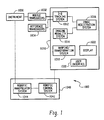
- FIG. 1 shows a three-dimensional (3-D) tracking and imaging system 1000 for use in connection with the procedure of the present invention.
- 3-D tracking and imaging system 1000 is generally comprised of a computer system 1010, mobile transducers 1032, reference transducers 1034, an instrument 1030 and an optional robotics subsystem 1040.
- Computer system 1010 is generally comprised of a 3-D tracking system 1012, an imaging modality system 1014, an image registration system 1016, a warping and geometry transformation system 1018 ("warp system"), a user interface 1020 and a display 1022.
- 3-D tracking system 1012 may take the form of a sound-based system or an electromagnetic-based system. Both time of flight and phase relationships may be used to determine distance.
- 3-D tracking system 1012 takes the form of the 3-D ultrasound tracking system described in U.S. Patent No. 5,515,853 and PCT Application No. WO96/31753, both of which are incorporated herein by reference.
- Instrument 1030 may take the form of a catheter, a probe (e.g., a cryoprobe), a sensor, a needle, a scalpel, a forceps or other device or instrument used in a surgical or diagnostic procedure.
- Mobile transducers 1032 and reference transducers 1034 may take the form of an ultrasonic transducer or an electronic transducer. However, for purpose of illustrating a preferred embodiment of the present invention, transducers 1032 and 1034 will take the form of ultrasonic transducers (i.e., piezoelectric crystals).
- a plurality of mobile transducers 1032 are fitted to instrument 1030.
- One or more reference transducers 1034 provide a reference position relative to mobile transducers 1032.
- reference transducers 1034 may be located to provide an internal reference frame inside a patient's body or on the surface of a patient body to provide an external reference frame.
- reference transducers 1034 may be transmitters, transceivers or receivers that can generate ultrasound or electromagnetic radiation, that can be detected by mobile transducers 1032.
- 3-D tracking system 1012 transforms the multiple distance measurements between all of the transducers 1032, 1034 into XYZ coordinates relative to a referenced axis, as described in detail above. It should be appreciated that the reference frame provided by reference transducers 1034 must be self-determining, that is, if the reference frame becomes distorted, this distortion needs to be detected by reference transducers 1034. Detection is typically done by using transceivers that can determine the distance between any combination of two transducers, and hence their relative spacial coordinates in 3-D space.
- the position of the transducers is obtained in 3-D from the images acquired of the bodily structure (e.g., tissue or organ) that show "dots" where the transducers are located, and also from the transducers themselves when they are in the bodily structure. If there is some discrepancy in the distances between all combinations of transducers, then the bodily structure must have deformed (i.e., "warped") after the images were acquired.
- a mathematical coordinate transformation can be used to specify exactly how to correct the image set and account for the warping.
- the distance between any combination of two transducers is determined by having each transducer send a signal to all other transducers. In this way, all the distances between the transducers are known. From these distances, XYZ coordinates can be calculated, in reference to some transducer as the origin.
- Imaging modality system 1014 acquires 2-D, 3-D or 4-D image data sets from an imaging source, such as fluoroscopy, an MRI (magnetic resonance imaging), CT (computerized tomography) or 2-D or 3-D ultrasound device, to provide a "template" through or against which the shape, position and movement of instrument 1030 being tracked can be displayed.
- the template typically takes the form of an image of the environment surrounding the instrument (e.g., a bodily structure). It should be noted that if multiple (3-D) volumes are acquired at different time intervals, a 4-D image is obtained (i.e., 3-D image changing over time).
- Image registration system 1016 registers the position of instrument 1030 within the spatial coordinates of the image data set provided by imaging modality system 1014.
- the position of instrument 1030 is provided by the 3-D tracking system 1012.
- Image registration system 1016 will provide a display of instrument 1030 at its proper 3-D location inside the bodily structure and orientation relative to the bodily structure itself. It should be appreciated that registration system 1016 may be user assisted, or completely automated if image processing algorithms are implemented to automatically detect the spacial locations of the transducers (typically the reference transducers) in the image data set.
- Warp system 1018 is a software-based system that transforms or "warps" the image data sets by the appropriate values to correspond to a deformation that has occurred in the reference frame between the time that the image data set were acquired and the time that the procedure is to be implemented during surgery. Accordingly, warp system 1018 is typically comprised of a matrix transformation routine that maps the deformed geometry onto the original image data set, and distorts it appropriately.
- User interface 1020 enables a user to interact with computer system 1010, including programming computer system 1010 to perform a desired function. For example, a particular view for display can be selected. Instruments 1030 (e.g., probes or catheters) can be activated using user interface 1020. Display 1022 displays to the user registered images provided by image registration system 1016.
- Instruments 1030 e.g., probes or catheters
- Display 1022 displays to the user registered images provided by image registration system 1016.
- Optional robotics system 1040 is generally comprised of a robotics control system 1042 and a robotic manipulator system 1044.
- Robotics control system 1042 controls robotic manipulator system 1044 to follow a programmed path that can be appropriately changed, based on shifting, warping or changes in the shape of a bodily structure at the time of surgery.
- Robotic manipulator system 1044 physically moves instrument 1030 as instructed by robotic control system 1042.
- the above-described 3-D tracking and imaging system 1000 can be used to provide both stereotactic localization during biopsy and surgery that is more interdetive than existing stereotaxy table systems, and tagging of a tumor so that it can subsequently be localized during conventional surgery. It should be appreciated that while the present invention is described with reference to the biopsy and ablation of a tumor, it is also suitable for use in connection with other physical anomalies.
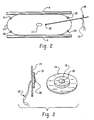
- FIG. 2 Tagging of a tumor located in a breast will now be described with reference to Fig. 2.
- a plurality of external reference transducers 20 are affixed to the surface of breast 10.
- Reference transducers 20 provide a stereotactic external reference frame for the interactive 3-D display of the movement of probe 40 during insertion of internal transducer 30, as will be described below.
- Tumor 12 is tagged by inserting internal ultrasonic transducer 30 into tumor 12 during conventional mammography, wherein breast 10 is placed under compression by the use of compression plates 8.
- Transducer 30 takes the place of the localizer needle that is presently inserted into the tumor according to prior art methods.
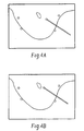
- Reference transducers 20 may take the form of individual stick-on elements, or part of an adhesive strip.
- Fig. 3 shows an exemplary embodiment of an arrangement for affixing reference transducer 20 using an adhesive.
- Reference transducer 20 is supported by an adhesive patch 24.
- a matching gel 26 is applied to the adhesive patch 24 and reference transducer 20 is arranged therein. Gel 26 provides acoustic coupling. Electrical leads 22 of reference transducer 20 exit through an opening in adhesive patch 24.
- reference transducers 20 will appear on the two mammograms obtained from at two slightly different angles, and can be used to generate fiducial markers for the stereographic determination of 3-D coordinates of tumor 12, relative to these markers.
- the motion of probe 40 can also be referenced against these bi- plane mammograms using transducer 30. Accordingly, a user can track the motion of probe 40 both in a 3-D viewing environment, as well as against the original radiograms, during the deposition of transducer 30, which will act as a "homing beacon" for the tumor during subsequent biopsy or surgery.
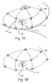
- the progression of an instrument through a breast is shown against mammograms in Figs. 4A and 4B.
- transducer 30 Once transducer 30 has been deposited in tumor 12, and probe 40 removed from the breast 10, the patient can comfortably walk around, since electrical leads 32 connected to transducer 30 are very flexible, and can be taped to the patient's skin. It should be appreciated that transducer 30 can reliably denote the location of tumor 12 during subsequent surgery since it remains lodged in tumor 12 by means of small barbs that deploy during insertion.
- the foregoing approach is a significant improvement over conventional stereotaxy. Since a tremendous change occurs in the shape of the breast between mammography and surgery, the tumor may be in a completely different location than previously perceived during mammography. As a result, any stercotactic registration of external breast shape with the internal breast images is lost. However, since the tumor is tagged with transducer 30, its location can always be determined during subsequent procedures.
- Transducers 20 and 30 are connected to the 3-D tracking and imaging system described above. It should be appreciated that transducers 20 and 30 enable the tracking of additional transducers that may be inserted into the breast during subsequent surgery.
- Fig. 5A shows breast 10 having tumor 12 tagged with internal transducer 30.
- the attachment of external reference transducers 20 and the presence of internal transducer 30 in tumor 12 enables the generation of a 3-D viewing environment within which tumor 12 can be localized relative to breast 10 (Fig. 5B).
- This means of visualizing the spatial location of tumor 12 relative to the outside of breast 10 is important in planning the tumor removal surgery.
- the conventional technique is to simply follow a previously inserted wire into the breast. This is not desirable since it may not be the most cosmetically desirable path to take.
- a surgeon can decide from which direction to begin incisions.
- a secondary probe 50 can be touched into the wound to determine if the trajectory should be modified.
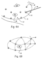
- Fig 6A shows probe 50 touching breast 10.
- probe 50 has a transducer 52 arranged on its tip.
- a 3-D display as shown in Fig. 6B can be generated.
- transducer 52 mounted to probe 50 comes into contact with the tissue, it will appear in the 3-D display and can be localized relative to transducer 30 (i.e.,"homing beacon"). Accordingly, the 3-D display allows the surgical path to be visualized and corrected, as necessary. Because the external reference frame formed by reference transducers 20 is affixed to the externat surface of breast 10, it does not matter if the breast tissue deforms following mammogram imaging.
- transducer 30 will always be shown relative to the new configuration of transducers 20 affixed to the external surface of breast 10. Moreover, since external reference transducers 20 communicate with each other, they will set up a new, changing coordinate frame regardless to what extent the breast tissue is manipulated. In each case, the relative position of transducer 30 is displayed within this coordinate system.
- the present invention may also be used to locate an instrument at a tumor site, according to another embodiment of the present invention.
- Fig. 7 shows a liver 60 having a tumor 14.
- a 3-dimensional reference frame of liver 60 is established by attaching a plurality of reference transducers 90 to the external surface of liver 60.
- transducers 90 may be attached under laparoscopic guidance.
- the location of tumor 14 is determined using guided 2-dimensional ultrasound 110, which generates a 2-D ultrasound imaging plane 112.
- a 2-D ultrasound imaging plane is displayed within the 3-D reference frame to form a 3-D scene.
- the user places a cursor mark in the 3-D scene to identify the center of tumor 14.
- the 3-D tracking and imaging system determines the 3-D coordinates of tumor 14 within the 3-D scene, relative to the 3-D reference frame established by transducers 90. It should be appreciated that since transducers 90 are fixed to liver 60, the location of tumor 14 remains fixed relative to the 3-D reference frame, even as liver 60 itself is manipulated causing deformation of liver 60.
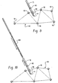
- a cryoprobe 100 (or other instrument) is located at tumor 14.
- an ultrasonically locatable sheath attachment 70 is inserted into liver 60 and positioned such that its end corresponds to the location of tumor 14.
- Sheath attachment 70 preferably takes the form of a hollow rigid sleeve or tube having transducers 80 mounted thereto.
- a preferred sheath attachment 70 is described in detail in US-A-5868673, incorporated herein by reference.
- Transducers 80 allow the position of sheath attachment 70 to be tracked using the 3-D tracking and imaging system, described above.
- cryoprobe 100 is inserted into sheath attachment 70, such that it stops at the mouth of the sheath. Accordingly, cryoprobe 100 does not require physical modifications to be located at the site of tumor 14.
- sheath attachment 70 is pulled back along the shaft of cryoprobe 100. Thereafter, cryoprobe 100 is energized to ablate tumor 14 in a well known manner.
- the foregoing procedure can be performed by inserting a trackable blunt guide instrument having ultrasonic transducers mounted thereto and locating the guide instrument at the site of the tumor.
- a tube or sleeve is placed at the site of the tumor by placing the tube over the guide instrument.
- the guide instrument is removed, leaving just the sleeve.
- a cryoprobe (or other instrument) is then inserted through the sleeve, thus locating the cryoprobe at the site of the tumor.
Abstract
Description
- The present application is a continuation-in-part (CIP) of co-pending International Application No. PCT/CA96/00194, filed March 26, 1996, which is a continuation-in-part (CIP) of U.S. Application Serial No. 08/411,959, filed March 28, 1995, now U.S. Patent No. 5,515,853. The contents of both applications are incorporated herein by reference.
- The present invention relates generally to a system for carrying out a surgical procedure on a bodily structure (e.g., breast, liver, pancreas, kidney, uterus or other solid organ), and more particularly to a system for tracking an instrument within a bodily structure, marking the location of a tumor, and biopsying or destroying the tumor.
- Breast biopsies are currently performed using a device known as a Core Biopsy System. The Core Biopsy system first obtains a stereo-mammogram from a patient's breast, while the breast is immobilized by being compressed between two plates, and uses these two images to calculate the 3-D coordinates of the suspected tumor. A needle is then fired into the breast and a biopsy is taken of the suspected tumor. If the biopsy is positive, then the patient is scheduled for tumor removal surgery. It should be noted that before the biopsy procedure is commenced, the tumor needs to be manually identified by a radiologist.
- The surgical procedure generally proceeds in the following manner. A patient undergoes multi-plane mammography, a radiologist examines the film, and then inserts a wire into the breast so that it punctures the tumor. This procedure is visualized using repetitive x-ray imaging. More recently, the stereotactic breast imaging system has been used to localize the tumor more precisely and assist in the insertion of the wire. The patient is then sent to the operating room, and the breast is prepared for surgery by the application of a topical sterilant. The surgeon then cuts the breast open, following the wire until the lesion is found and excised.
- One of the undesirable factors of the foregoing procedure is the presence of a long wire through the breast for many hours at a time while awaiting surgery. This is highly traumatic for the patient and undesirable. Secondly, during surgery, the surgeon must follow the wire into the breast. Since this may not be the optimal trajectory, the surgeon would ideally like to plan the entry pathway independent of the wire, or eliminate the wire altogether. This can be done only if the location of the lesion within the breast can be identified using a system that takes into account the inherent deformability of the breast tissue. It should be appreciated that the problem associated with the deformability of breast tissue applies equally to other easily deformable bodily structures such as the liver. Another approach to stereotactic surgery is described in European patent publication no. EP 0 728 446 A1. This publication discloses a stereotaxy system and method, with particular application to breast surgery. The patient is examined with magnetic resonance or other imaging device to generate a 3-D image representation for display on a monitor. Using magnetic resonance visible marker, which are affixed to the exoskeleton material adjacent the soft tissue, a wand with emitter and receivers, and a coordinate system relationship processor, the relationship is determined between a coordinate system of the patient and a coordinate system of the image displayed on a monitor. A trajectory for a biopsy, resection, or the like is planned using a stereotaxy guide, which is fixed to a patient support structure. Emitters on the guide are activated to generate a corresponding human-readable trajectory display through the image displayed on the monitor. An appropriate trajectory and depth is selected from the human-readable trajectory display, and a medical instrument is inserted along the guide to perform the medical procedure.
- The current problem limiting use of stereotactic breast surgery is the large difference between the position and shape of the breast during mammography and surgery. In this regard, images taken during mammography become unusable for stereotactic positioning during the surgical procedure. While stereotactic surgery can be done with the breast compressed, and the patient lying on the stereotactic table, this is not desirable. The ideal way to do this surgery is with the patient on her back, as is done routinely.
- The present invention overcomes these and other drawbacks of prior art systems and provides a system having significantly improved accuracy and providing greater comfort to the patient.
- It is still another object of the present invention to provide a system for performing surgery, wherein a constant 3-D reference frame is established.
- It is still another object of the present invention to provide a system for performing surgery, wherein deformation of the subject bodily structure docs not alter a 3-D frame of reference.
- It is yet another object of the present invention to provide a system for performing breast surgery in which there is greatly reduced potential for disfiguring or altering the shape of the breast.
- It is yet another object of the present invention to provide a system for performing surgery of the liver, or other internal organ, in which there is more accurate locating of a tumor.
- It is yet another object of the present invention to provide a system for performing surgery of the liver, or other organ, in which there is a need for more accurate locating of a surgical instrument.
- Still other objects and advantages of the invention will become apparent to those skilled in the art upon a reading and understanding of the following detailed description, accompanying drawings and appended claims.
- The invention may take physical form in certain parts and arrangements of parts, a preferred embodiment and method of which will be described in detail in this specification and illustrated in the accompanying drawings which form a part hereof, and wherein:
- Fig. 1 shows a 3-dimensional tracking and imaging system according to a preferred embodiment of the present invention.
- Fig. 2 shows a breast having a reference transducer deposited therein while the breast is under compression;
- Fig. 3 shows a transducer arrangement according to a preferred embodiment of the present invention;
- Figs. 4A and 4B illustrates the progression of a probe through a breast shown against the original stereo mammograms;
- Fig. 5A shows reference transducers and a "homing beacon" transducer located on a breast;
- Fig. 5B shows the scene of Fig. 5A, as shown in 3-D on a display unit;
- Fig. 6A shows a probe having a transducer in contact with the breast shown in Fig. 4A;
- Fig. 6B shows the scene of Fig. 6A, as shown in 3-D on a display unit;
- Fig. 7 shows a liver having a plurality of reference transducers applied thereto;
- Fig. 8 illustrates a procedure for generating a 3-D scene including a 2-D ultrasound image of the liver shown in Fig. 7.
- Fig. 9 shows insertion of a locatable tube into the liver shown in Fig. 7; and
- Fig. 10 shows the insertion of a cryoprobe into a trackable sleeve located at the site of a tumor.
-
- It is known that using the time-of-flight principle of high frequency sound waves, it is possible to accurately measure distances within an aqueous medium, such as inside the body of a living being during a surgical procedure. High frequency sound, or ultrasound, is defined as vibrational energy that ranges in frequency from 100 kHz to 10 MHz. The device used to obtain three-dimensional measurements using sound waves is known as a sonomicrometer. Typically, a sonomicrometer consists of a pair of piezoelectric transducers (i.e., one transducer acts as a transmitter while the other transducer acts as a receiver). The transducers are implanted into a medium, and connected to electronic circuitry. To measure the distance between the transducers, the transmitter is electrically energized to produce ultrasound. The resulting sound wave then propagates through the medium until it is detected by the receiver.
- The transmitter typically takes the form of a piezoelectric crystal that is energized by a high voltage spike, or impulse function lasting under a microsecond. This causes the piezoelectric crystal to oscillate at its own characteristic resonant frequency. The envelope of the transmitter signal decays rapidly with time, usually producing a train of six or more cycles that propagate away from the transmitter through the aqueous medium. The sound energy also attenuates with every interface that it encounters.
- The receiver also typically takes the form of a piezoelectric crystal (with similar characteristics to the transmitter piezoelectric crystal) that detects the sound energy produced by the transmitter and begins to vibrate in response thereto. This vibration produces an electronic signal in the order of millivolts, that can be amplified by appropriate receiver circuitry.
- The propagation velocity of ultrasound in an aqueous medium is well documented. The distance traveled by a pulse of ultrasound can therefore be measured simply by recording the time delay between the instant the sound is transmitted and when it is received. Three-dimensional coordinates can be determined from the distance measurement.
- Referring now to the drawings wherein the showings are for the purposes of illustrating a preferred embodiment of the invention only and not for purposes of limiting same, Fig. 1 shows a three-dimensional (3-D) tracking and
imaging system 1000 for use in connection with the procedure of the present invention. 3-D tracking andimaging system 1000 is generally comprised of acomputer system 1010,mobile transducers 1032,reference transducers 1034, aninstrument 1030 and anoptional robotics subsystem 1040. -
Computer system 1010 is generally comprised of a 3-D tracking system 1012, animaging modality system 1014, animage registration system 1016, a warping and geometry transformation system 1018 ("warp system"), auser interface 1020 and adisplay 1022. It should be appreciated that 3-D tracking system 1012 may take the form of a sound-based system or an electromagnetic-based system. Both time of flight and phase relationships may be used to determine distance. Preferably, 3-D tracking system 1012 takes the form of the 3-D ultrasound tracking system described in U.S. Patent No. 5,515,853 and PCT Application No. WO96/31753, both of which are incorporated herein by reference. -
Instrument 1030 may take the form of a catheter, a probe (e.g., a cryoprobe), a sensor, a needle, a scalpel, a forceps or other device or instrument used in a surgical or diagnostic procedure.Mobile transducers 1032 andreference transducers 1034 may take the form of an ultrasonic transducer or an electronic transducer. However, for purpose of illustrating a preferred embodiment of the present invention,transducers - A plurality of
mobile transducers 1032 are fitted toinstrument 1030. One ormore reference transducers 1034 provide a reference position relative tomobile transducers 1032. In this respect,reference transducers 1034 may be located to provide an internal reference frame inside a patient's body or on the surface of a patient body to provide an external reference frame. - As indicated above,
reference transducers 1034 may be transmitters, transceivers or receivers that can generate ultrasound or electromagnetic radiation, that can be detected bymobile transducers 1032. - 3-
D tracking system 1012 transforms the multiple distance measurements between all of thetransducers reference transducers 1034 must be self-determining, that is, if the reference frame becomes distorted, this distortion needs to be detected byreference transducers 1034. Detection is typically done by using transceivers that can determine the distance between any combination of two transducers, and hence their relative spacial coordinates in 3-D space. In this regard, the position of the transducers is obtained in 3-D from the images acquired of the bodily structure (e.g., tissue or organ) that show "dots" where the transducers are located, and also from the transducers themselves when they are in the bodily structure. If there is some discrepancy in the distances between all combinations of transducers, then the bodily structure must have deformed (i.e., "warped") after the images were acquired. A mathematical coordinate transformation can be used to specify exactly how to correct the image set and account for the warping. The distance between any combination of two transducers is determined by having each transducer send a signal to all other transducers. In this way, all the distances between the transducers are known. From these distances, XYZ coordinates can be calculated, in reference to some transducer as the origin. -
Imaging modality system 1014 acquires 2-D, 3-D or 4-D image data sets from an imaging source, such as fluoroscopy, an MRI (magnetic resonance imaging), CT (computerized tomography) or 2-D or 3-D ultrasound device, to provide a "template" through or against which the shape, position and movement ofinstrument 1030 being tracked can be displayed. The template typically takes the form of an image of the environment surrounding the instrument (e.g., a bodily structure). It should be noted that if multiple (3-D) volumes are acquired at different time intervals, a 4-D image is obtained (i.e., 3-D image changing over time). -
Image registration system 1016 registers the position ofinstrument 1030 within the spatial coordinates of the image data set provided byimaging modality system 1014. The position ofinstrument 1030 is provided by the 3-D tracking system 1012.Image registration system 1016 will provide a display ofinstrument 1030 at its proper 3-D location inside the bodily structure and orientation relative to the bodily structure itself. It should be appreciated thatregistration system 1016 may be user assisted, or completely automated if image processing algorithms are implemented to automatically detect the spacial locations of the transducers (typically the reference transducers) in the image data set. -
Warp system 1018 is a software-based system that transforms or "warps" the image data sets by the appropriate values to correspond to a deformation that has occurred in the reference frame between the time that the image data set were acquired and the time that the procedure is to be implemented during surgery. Accordingly,warp system 1018 is typically comprised of a matrix transformation routine that maps the deformed geometry onto the original image data set, and distorts it appropriately. -
User interface 1020 enables a user to interact withcomputer system 1010, includingprogramming computer system 1010 to perform a desired function. For example, a particular view for display can be selected. Instruments 1030 (e.g., probes or catheters) can be activated usinguser interface 1020.Display 1022 displays to the user registered images provided byimage registration system 1016. -
Optional robotics system 1040 is generally comprised of arobotics control system 1042 and arobotic manipulator system 1044.Robotics control system 1042 controlsrobotic manipulator system 1044 to follow a programmed path that can be appropriately changed, based on shifting, warping or changes in the shape of a bodily structure at the time of surgery.Robotic manipulator system 1044 physically movesinstrument 1030 as instructed byrobotic control system 1042. - The above-described 3-D tracking and
imaging system 1000 can be used to provide both stereotactic localization during biopsy and surgery that is more interdetive than existing stereotaxy table systems, and tagging of a tumor so that it can subsequently be localized during conventional surgery. It should be appreciated that while the present invention is described with reference to the biopsy and ablation of a tumor, it is also suitable for use in connection with other physical anomalies. - Tagging of a tumor located in a breast will now be described with reference to Fig. 2. A plurality of
external reference transducers 20 are affixed to the surface ofbreast 10.Reference transducers 20 provide a stereotactic external reference frame for the interactive 3-D display of the movement ofprobe 40 during insertion ofinternal transducer 30, as will be described below.Tumor 12 is tagged by inserting internalultrasonic transducer 30 intotumor 12 during conventional mammography, whereinbreast 10 is placed under compression by the use ofcompression plates 8.Transducer 30 takes the place of the localizer needle that is presently inserted into the tumor according to prior art methods. -
Reference transducers 20 may take the form of individual stick-on elements, or part of an adhesive strip. Fig. 3 shows an exemplary embodiment of an arrangement for affixingreference transducer 20 using an adhesive.Reference transducer 20 is supported by anadhesive patch 24. A matchinggel 26 is applied to theadhesive patch 24 andreference transducer 20 is arranged therein.Gel 26 provides acoustic coupling. Electrical leads 22 ofreference transducer 20 exit through an opening inadhesive patch 24. - It should be appreciated that
reference transducers 20 will appear on the two mammograms obtained from at two slightly different angles, and can be used to generate fiducial markers for the stereographic determination of 3-D coordinates oftumor 12, relative to these markers. Moreover, the motion ofprobe 40 can also be referenced against these bi- planemammograms using transducer 30. Accordingly, a user can track the motion ofprobe 40 both in a 3-D viewing environment, as well as against the original radiograms, during the deposition oftransducer 30, which will act as a "homing beacon" for the tumor during subsequent biopsy or surgery. The progression of an instrument through a breast is shown against mammograms in Figs. 4A and 4B. - Once
transducer 30 has been deposited intumor 12, and probe 40 removed from thebreast 10, the patient can comfortably walk around, since electrical leads 32 connected totransducer 30 are very flexible, and can be taped to the patient's skin. It should be appreciated thattransducer 30 can reliably denote the location oftumor 12 during subsequent surgery since it remains lodged intumor 12 by means of small barbs that deploy during insertion. - The foregoing approach is a significant improvement over conventional stereotaxy. Since a tremendous change occurs in the shape of the breast between mammography and surgery, the tumor may be in a completely different location than previously perceived during mammography. As a result, any stercotactic registration of external breast shape with the internal breast images is lost. However, since the tumor is tagged with
transducer 30, its location can always be determined during subsequent procedures. - After the foregoing procedure, the patient goes to the operating room, the breast is prepared for surgery, and new adhesive, with ultrasonic transducers imbedded therein, are attached to the skin.
Transducers transducers - Fig. 5A shows
breast 10 havingtumor 12 tagged withinternal transducer 30. The attachment ofexternal reference transducers 20 and the presence ofinternal transducer 30 intumor 12 enables the generation of a 3-D viewing environment within whichtumor 12 can be localized relative to breast 10 (Fig. 5B). This means of visualizing the spatial location oftumor 12 relative to the outside ofbreast 10 is important in planning the tumor removal surgery. The conventional technique is to simply follow a previously inserted wire into the breast. This is not desirable since it may not be the most cosmetically desirable path to take. By analyzing a 3-D display, such as shown in Fig 5B, a surgeon can decide from which direction to begin incisions. - As the incisions are made, a
secondary probe 50 can be touched into the wound to determine if the trajectory should be modified. Fig 6A showsprobe 50 touchingbreast 10. It should be noted thatprobe 50 has atransducer 52 arranged on its tip. Accordingly, a 3-D display as shown in Fig. 6B can be generated. Oncetransducer 52 mounted to probe 50 comes into contact with the tissue, it will appear in the 3-D display and can be localized relative to transducer 30 (i.e.,"homing beacon"). Accordingly, the 3-D display allows the surgical path to be visualized and corrected, as necessary. Because the external reference frame formed byreference transducers 20 is affixed to the externat surface ofbreast 10, it does not matter if the breast tissue deforms following mammogram imaging. In this regard,transducer 30 will always be shown relative to the new configuration oftransducers 20 affixed to the external surface ofbreast 10. Moreover, sinceexternal reference transducers 20 communicate with each other, they will set up a new, changing coordinate frame regardless to what extent the breast tissue is manipulated. In each case, the relative position oftransducer 30 is displayed within this coordinate system. - The foregoing approach provides numerous advantages and overcomes the current limitations of stereotactic surgery that is based on a fixed coordinate system. With regard to clinical advantages, breast surgery can be done much less invasively. When developed further, it may be possible to remove tumors in a much less invasive way, by inserting small catheters that ablate, suction or in some other way destroy the tumor without having to open up the breast for visual inspection. This will greatly reduce the potential for disfiguring or altering the shape of the breast. Another important clinical advantage is the increased precision of the localization of the tumor, enabling more precise surgery. The theoretical precision of the 3-D tracking system described above is 20 um. In practice, the 3-D spatial precision is less than 1 mm, and due to geometrical transformation errors, this may rise to 2 nun. This is apparently still better than the precision currently available using the wire insertion technique or conventional stereotactic tables. Such increased precision will improve the success rate of tumor excision, without the need for larger, more radical lumpectomies. Yet another clinical advantage is that the foregoing procedure can be readily applied to both biopsies, open surgery or fully closed, minimally invasive surgery. It provides a real-time, user assisted means of approaching tumors inside the breast and is much less costly than conventional stereotactic equipment.
- The present invention may also be used to locate an instrument at a tumor site, according to another embodiment of the present invention. Fig. 7 shows a
liver 60 having atumor 14. A 3-dimensional reference frame ofliver 60 is established by attaching a plurality ofreference transducers 90 to the external surface ofliver 60. In this regard,transducers 90 may be attached under laparoscopic guidance. Next, the location oftumor 14 is determined using guided 2-dimensional ultrasound 110, which generates a 2-Dultrasound imaging plane 112. A 2-D ultrasound imaging plane is displayed within the 3-D reference frame to form a 3-D scene. Whentumor 14 is transected byultrasound imaging plane 112, the user places a cursor mark in the 3-D scene to identify the center oftumor 14. The 3-D tracking and imaging system determines the 3-D coordinates oftumor 14 within the 3-D scene, relative to the 3-D reference frame established bytransducers 90. It should be appreciated that sincetransducers 90 are fixed toliver 60, the location oftumor 14 remains fixed relative to the 3-D reference frame, even asliver 60 itself is manipulated causing deformation ofliver 60. - Referring now to Figs. 9 and 10 a cryoprobe 100 (or other instrument) is located at
tumor 14. In this respect, an ultrasonicallylocatable sheath attachment 70 is inserted intoliver 60 and positioned such that its end corresponds to the location oftumor 14.Sheath attachment 70 preferably takes the form of a hollow rigid sleeve ortube having transducers 80 mounted thereto. Apreferred sheath attachment 70 is described in detail in US-A-5868673, incorporated herein by reference.Transducers 80 allow the position ofsheath attachment 70 to be tracked using the 3-D tracking and imaging system, described above. - Once
sheath attachment 70 has been located at the site oftumor 14,cryoprobe 100 is inserted intosheath attachment 70, such that it stops at the mouth of the sheath. Accordingly,cryoprobe 100 does not require physical modifications to be located at the site oftumor 14. Next,sheath attachment 70 is pulled back along the shaft ofcryoprobe 100. Thereafter,cryoprobe 100 is energized to ablatetumor 14 in a well known manner. - Alternatively, the foregoing procedure can be performed by inserting a trackable blunt guide instrument having ultrasonic transducers mounted thereto and locating the guide instrument at the site of the tumor. Next, a tube or sleeve is placed at the site of the tumor by placing the tube over the guide instrument. Then, the guide instrument is removed, leaving just the sleeve. A cryoprobe (or other instrument) is then inserted through the sleeve, thus locating the cryoprobe at the site of the tumor.
- The invention has been described with reference to a preferred embodiment. Obviously, modifications and alterations will occur to others upon a reading and understanding of this specification. It is intended that all such modifications and alterations be included insofar as they come within the scope of the appended claims or the equivalents thereof. Further particular and preferred aspects of the invention are set out in the accompanying independent and dependent clauses. Features of the dependent clauses may be combined with those of the independent clauses and independent claims as appropriate and in combinations other than those explicitly set out in the clauses and claims.
- 1. A system for carrying out surgery on a tumor in a bodily structure for
the purpose of biopsy or ablation, comprising a plurality of reference transducer
means (20) located at fixed positions on the bodily structure to provide a reference
frame (1012); means for obtaining a template image of a bodily structure (1014);
registration means (1016) for registering the reference frame with the template image
to obtain a 3-dimensional scene; and display means (1022) for displaying the 3-dimensional
scene of the bodily structure, characterized by:
- first instrument means (40) for fixing the location of a beacon transducer means (30) at the site of a tumor to identify the location of the tumor; and
- second instrument means (1030) for performing a surgical procedure at the site of the tumor, wherein the second instrument means has a transducer means (1032) for indicating the position of the second instrument means relative to the reference frame and the location of the beacon transducer means.
- 2. A system according to clause 1, wherein said fixed positions are on the surface of a breast.
- 3. A system according to clause 1, wherein said fixed positions are on the external surface of a solid organ.
- 4. A system according to
clause 1, 2 or 3, wherein said template image is a mammogram. - 5. A system according to
clause 1, 2 or 3, wherein said template image is a radiological image. - 6. A system according to any one of the preceding clauses, wherein said first instrument means includes means for separating said beacon transducer means from said first instrument means.
- 7. A system according to any one of the preceding clauses, wherein each
of said plurality of reference transducer means (20) comprises:
- a transducer device; and
- support means (24) for supporting the transducer device, said support means including an adhesive for affixing the transducer device to the fixed position on the bodily structure and a gel (26) for acoustic coupling.
- 8. A system according to clause 7, wherein said transducer device includes a piezoelectric material.
-
Claims (5)
- A system for carrying out surgery on an anomaly in a bodily structure for the purpose of biopsy or ablation, comprising a plurality of reference transducer means (90) mounted at fixed positions on a bodily structure to provide a reference frame (1012); means for obtaining a template image of the bodily structure (1014); registration means (1016) for registering the reference frame with the template image to obtain a 3-dimensional scene;
trackable sleeve means (70) locatable at the location of an associated anomaly to identify a location of the associated anomaly;
display means (1022) adapted for displaying the position of a trackable sleeve means within the 3-dimensional scene to locate the sleeve means at the location of the associated anomaly; and
first instrument means (100) adapted for performing a surgical procedure at the location of the associated anomaly, the first instrument means located at the location of the associated anomaly by positioning the first instrument means within the sleeve means. - A system according to claim 1, wherein said fixed positions are located on an external surface of a solid organ.
- A system according to claim 1 or 2, wherein said template image is a 2-dimensional ultrasound image.
- A system according to any preceding claim, wherein said system further comprises means for displaying a reference mark in the 3-dimensional scene at the location of the associated anomaly to facilitate locating the trackable sleeve means at the location of the associated anomaly.
- A system according to any preceding claim, wherein said first instrument means is a cryoprobe.
Applications Claiming Priority (3)
| Application Number | Priority Date | Filing Date | Title |
|---|---|---|---|
| US815141 | 1997-03-11 | ||
| US08/815,141 US5868673A (en) | 1995-03-28 | 1997-03-11 | System for carrying out surgery, biopsy and ablation of a tumor or other physical anomaly |
| EP98917521A EP0998238B1 (en) | 1997-03-11 | 1998-03-11 | System for carrying out surgery, biopsy and ablation of a tumor or other physical anomaly |
Related Parent Applications (1)
| Application Number | Title | Priority Date | Filing Date |
|---|---|---|---|
| EP98917521A Division EP0998238B1 (en) | 1997-03-11 | 1998-03-11 | System for carrying out surgery, biopsy and ablation of a tumor or other physical anomaly |
Publications (2)
| Publication Number | Publication Date |
|---|---|
| EP1306060A1 true EP1306060A1 (en) | 2003-05-02 |
| EP1306060B1 EP1306060B1 (en) | 2005-11-16 |
Family
ID=25216983
Family Applications (2)
| Application Number | Title | Priority Date | Filing Date |
|---|---|---|---|
| EP98917521A Expired - Lifetime EP0998238B1 (en) | 1997-03-11 | 1998-03-11 | System for carrying out surgery, biopsy and ablation of a tumor or other physical anomaly |
| EP03001438A Expired - Lifetime EP1306060B1 (en) | 1997-03-11 | 1998-03-11 | System for carrying out surgery biopsy and ablation of a tumor or other physical anomaly |
Family Applications Before (1)
| Application Number | Title | Priority Date | Filing Date |
|---|---|---|---|
| EP98917521A Expired - Lifetime EP0998238B1 (en) | 1997-03-11 | 1998-03-11 | System for carrying out surgery, biopsy and ablation of a tumor or other physical anomaly |
Country Status (8)
| Country | Link |
|---|---|
| US (1) | US5868673A (en) |
| EP (2) | EP0998238B1 (en) |
| JP (1) | JP3415164B2 (en) |
| AT (2) | ATE251424T1 (en) |
| AU (1) | AU7072898A (en) |
| DE (2) | DE69832425T2 (en) |
| ES (1) | ES2256598T3 (en) |
| WO (1) | WO1998040026A1 (en) |
Cited By (1)
| Publication number | Priority date | Publication date | Assignee | Title |
|---|---|---|---|---|
| WO2022215075A1 (en) * | 2021-04-08 | 2022-10-13 | Mazor Robotics Ltd. | Tracking soft tissue changes intraoperatively |
Families Citing this family (280)
| Publication number | Priority date | Publication date | Assignee | Title |
|---|---|---|---|---|
| US6983179B2 (en) | 1993-07-20 | 2006-01-03 | Biosense, Inc. | Method for mapping a heart using catheters having ultrasonic position sensors |
| US6285898B1 (en) | 1993-07-20 | 2001-09-04 | Biosense, Inc. | Cardiac electromechanics |
| US5868673A (en) | 1995-03-28 | 1999-02-09 | Sonometrics Corporation | System for carrying out surgery, biopsy and ablation of a tumor or other physical anomaly |
| US6246898B1 (en) * | 1995-03-28 | 2001-06-12 | Sonometrics Corporation | Method for carrying out a medical procedure using a three-dimensional tracking and imaging system |
| US6256529B1 (en) | 1995-07-26 | 2001-07-03 | Burdette Medical Systems, Inc. | Virtual reality 3D visualization for surgical procedures |
| US6915149B2 (en) | 1996-01-08 | 2005-07-05 | Biosense, Inc. | Method of pacing a heart using implantable device |
| JP2001505071A (en) * | 1996-03-27 | 2001-04-17 | メドネティックス・アクチエンゲゼルシヤフト | Apparatus and method for position measurement |
| US5799055A (en) * | 1996-05-15 | 1998-08-25 | Northwestern University | Apparatus and method for planning a stereotactic surgical procedure using coordinated fluoroscopy |
| USRE40176E1 (en) * | 1996-05-15 | 2008-03-25 | Northwestern University | Apparatus and method for planning a stereotactic surgical procedure using coordinated fluoroscopy |
| US6167296A (en) * | 1996-06-28 | 2000-12-26 | The Board Of Trustees Of The Leland Stanford Junior University | Method for volumetric image navigation |
| AU735196B2 (en) * | 1997-01-03 | 2001-07-05 | Biosense, Inc. | Conformal catheter |
| US6314310B1 (en) * | 1997-02-14 | 2001-11-06 | Biosense, Inc. | X-ray guided surgical location system with extended mapping volume |
| US6731966B1 (en) * | 1997-03-04 | 2004-05-04 | Zachary S. Spigelman | Systems and methods for targeting a lesion |
| US6490474B1 (en) * | 1997-08-01 | 2002-12-03 | Cardiac Pathways Corporation | System and method for electrode localization using ultrasound |
| US6027451A (en) | 1997-09-26 | 2000-02-22 | Ep Technologies, Inc. | Method and apparatus for fixing the anatomical orientation of a displayed ultrasound generated image |
| US6259941B1 (en) * | 1997-10-20 | 2001-07-10 | Irvine Biomedical, Inc. | Intravascular ultrasound locating system |
| US6246899B1 (en) * | 1997-10-20 | 2001-06-12 | Irvine Biomedical, Inc. | Ultrasound locating system having ablation capabilities |
| US6233477B1 (en) * | 1997-10-20 | 2001-05-15 | Irvine Biomedical, Inc. | Catheter system having controllable ultrasound locating means |
| US6129670A (en) * | 1997-11-24 | 2000-10-10 | Burdette Medical Systems | Real time brachytherapy spatial registration and visualization system |
| CA2333583C (en) * | 1997-11-24 | 2005-11-08 | Everette C. Burdette | Real time brachytherapy spatial registration and visualization system |
| US20030036746A1 (en) * | 2001-08-16 | 2003-02-20 | Avi Penner | Devices for intrabody delivery of molecules and systems and methods utilizing same |
| US6175760B1 (en) * | 1998-02-17 | 2001-01-16 | University Of Iowa Research Foundation | Lesion localizer for nuclear medicine |
| US6360116B1 (en) | 1998-02-27 | 2002-03-19 | Varian Medical Systems, Inc. | Brachytherapy system for prostate cancer treatment with computer implemented systems and processes to facilitate pre-operative planning and post-operative evaluations |
| US6327490B1 (en) | 1998-02-27 | 2001-12-04 | Varian Medical Systems, Inc. | Brachytherapy system for prostate cancer treatment with computer implemented systems and processes to facilitate pre-implantation planning and post-implantation evaluations with storage of multiple plan variations for a single patient |
| GB2335744A (en) * | 1998-03-27 | 1999-09-29 | Intravascular Res Ltd | Medical ultrasonic imaging |
| US6363940B1 (en) | 1998-05-14 | 2002-04-02 | Calypso Medical Technologies, Inc. | System and method for bracketing and removing tissue |
| US6129669A (en) * | 1998-05-22 | 2000-10-10 | Scimed Life Systems, Inc. | Systems and methods for assessing stability of an ablation electrode in contact with heart tissue |
| US6950689B1 (en) * | 1998-08-03 | 2005-09-27 | Boston Scientific Scimed, Inc. | Dynamically alterable three-dimensional graphical model of a body region |
| US7517348B2 (en) * | 1998-09-03 | 2009-04-14 | Rubicor Medical, Inc. | Devices and methods for performing procedures on a breast |
| US6214018B1 (en) | 1998-11-04 | 2001-04-10 | Trex Medical Corporation | Method and apparatus for removing tissue from a region of interest using stereotactic radiographic guidance |
| US6122542A (en) * | 1998-11-25 | 2000-09-19 | Rubicor Medical, Inc. | Breast stabilization devices and imaging and interventional methods using the same |
| US7174201B2 (en) * | 1999-03-11 | 2007-02-06 | Biosense, Inc. | Position sensing system with integral location pad and position display |
| US7575550B1 (en) | 1999-03-11 | 2009-08-18 | Biosense, Inc. | Position sensing based on ultrasound emission |
| US7558616B2 (en) * | 1999-03-11 | 2009-07-07 | Biosense, Inc. | Guidance of invasive medical procedures using implantable tags |
| US7549960B2 (en) * | 1999-03-11 | 2009-06-23 | Biosense, Inc. | Implantable and insertable passive tags |
| US7590441B2 (en) * | 1999-03-11 | 2009-09-15 | Biosense, Inc. | Invasive medical device with position sensing and display |
| US6144875A (en) * | 1999-03-16 | 2000-11-07 | Accuray Incorporated | Apparatus and method for compensating for respiratory and patient motion during treatment |
| AU5561400A (en) * | 1999-07-02 | 2001-01-22 | Ultra-Guide Ltd. | Apparatus and methods for medical interventions |
| US6574498B1 (en) | 1999-09-16 | 2003-06-03 | Super Dimension Ltd. | Linking of an intra-body tracking system to external reference coordinates |
| DE19956814B4 (en) * | 1999-11-25 | 2004-07-15 | Brainlab Ag | Shape detection of treatment devices |
| US6515657B1 (en) | 2000-02-11 | 2003-02-04 | Claudio I. Zanelli | Ultrasonic imager |
| EP1274360A1 (en) * | 2000-04-10 | 2003-01-15 | 2C3D S.A. | Medical device for positioning data on intraoperative images |
| US6351660B1 (en) * | 2000-04-18 | 2002-02-26 | Litton Systems, Inc. | Enhanced visualization of in-vivo breast biopsy location for medical documentation |
| US20030135102A1 (en) * | 2000-05-18 | 2003-07-17 | Burdette Everette C. | Method and system for registration and guidance of intravascular treatment |
| US6494844B1 (en) * | 2000-06-21 | 2002-12-17 | Sanarus Medical, Inc. | Device for biopsy and treatment of breast tumors |
| JP2004505748A (en) * | 2000-08-23 | 2004-02-26 | ミクロニックス ピーティーワイ リミテッド | Catheter position display device and use thereof |
| US7024248B2 (en) * | 2000-10-16 | 2006-04-04 | Remon Medical Technologies Ltd | Systems and methods for communicating with implantable devices |
| US6540694B1 (en) | 2000-10-16 | 2003-04-01 | Sanarus Medical, Inc. | Device for biopsy tumors |
| JP4108473B2 (en) * | 2000-10-16 | 2008-06-25 | サナルス・メディカル・インコーポレイテッド | Tumor biopsy device |
| DE10194616D2 (en) * | 2000-10-23 | 2003-10-02 | Deutsches Krebsforsch | Method and device for navigation during medical interventions or for the fixation of a non-osseous structure |
| AU2002215822A1 (en) * | 2000-10-23 | 2002-05-06 | Deutsches Krebsforschungszentrum Stiftung Des Offentlichen Rechts | Method, device and navigation aid for navigation during medical interventions |
| EP2130511A1 (en) * | 2000-11-17 | 2009-12-09 | Calypso Medical, Inc | System for locating and defining a target location within a human body |
| US7594917B2 (en) | 2001-03-13 | 2009-09-29 | Ethicon, Inc. | Method and apparatus for fixing a graft in a bone tunnel |
| US6517546B2 (en) * | 2001-03-13 | 2003-02-11 | Gregory R. Whittaker | Method and apparatus for fixing a graft in a bone tunnel |
| US7195642B2 (en) | 2001-03-13 | 2007-03-27 | Mckernan Daniel J | Method and apparatus for fixing a graft in a bone tunnel |
| US20020193685A1 (en) * | 2001-06-08 | 2002-12-19 | Calypso Medical, Inc. | Guided Radiation Therapy System |
| US20030026758A1 (en) * | 2001-07-27 | 2003-02-06 | Baker Gregg S. | Method and device for monitoring real-time position of an area targeted by a radiosurgery system |
| US7135978B2 (en) * | 2001-09-14 | 2006-11-14 | Calypso Medical Technologies, Inc. | Miniature resonating marker assembly |
| JP2005503227A (en) * | 2001-09-27 | 2005-02-03 | ガリル メディカル リミテッド | Apparatus and method for cryosurgical treatment of breast tumors |
| AU2002337596A1 (en) * | 2001-09-27 | 2003-04-07 | Galil Medical Ltd. | Cryoplasty apparatus and method |
| WO2003032837A1 (en) * | 2001-10-12 | 2003-04-24 | University Of Florida | Computer controlled guidance of a biopsy needle |
| US20030093007A1 (en) * | 2001-10-17 | 2003-05-15 | The Government Of The U.S.A., As Represented By The Secretary, Department Of Health And Human Serv | Biopsy apparatus with radio frequency cauterization and methods for its use |
| FR2831743B1 (en) * | 2001-10-25 | 2004-01-30 | Cit Alcatel | IS-IS FAULT TOLERANT ROUTING SYSTEM AND CORRESPONDING METHOD |
| US7438685B2 (en) | 2001-11-05 | 2008-10-21 | Computerized Medical Systems, Inc. | Apparatus and method for registration, guidance and targeting of external beam radiation therapy |
| US6785572B2 (en) * | 2001-11-21 | 2004-08-31 | Koninklijke Philips Electronics, N.V. | Tactile feedback and display in a CT image guided robotic system for interventional procedures |
| US6812842B2 (en) | 2001-12-20 | 2004-11-02 | Calypso Medical Technologies, Inc. | System for excitation of a leadless miniature marker |
| US6822570B2 (en) | 2001-12-20 | 2004-11-23 | Calypso Medical Technologies, Inc. | System for spatially adjustable excitation of leadless miniature marker |
| US6838990B2 (en) | 2001-12-20 | 2005-01-04 | Calypso Medical Technologies, Inc. | System for excitation leadless miniature marker |
| US6780179B2 (en) * | 2002-05-22 | 2004-08-24 | Rubicor Medical, Inc. | Methods and systems for in situ tissue marking and orientation stabilization |
| US7187800B2 (en) * | 2002-08-02 | 2007-03-06 | Computerized Medical Systems, Inc. | Method and apparatus for image segmentation using Jensen-Shannon divergence and Jensen-Renyi divergence |
| WO2004019799A2 (en) * | 2002-08-29 | 2004-03-11 | Computerized Medical Systems, Inc. | Methods and systems for localizing of a medical imaging probe and of a biopsy needle |
| US7926491B2 (en) * | 2002-12-31 | 2011-04-19 | Calypso Medical Technologies, Inc. | Method and apparatus for sensing field strength signals to estimate location of a wireless implantable marker |
| US7289839B2 (en) * | 2002-12-30 | 2007-10-30 | Calypso Medical Technologies, Inc. | Implantable marker with a leadless signal transmitter compatible for use in magnetic resonance devices |
| US9248003B2 (en) * | 2002-12-30 | 2016-02-02 | Varian Medical Systems, Inc. | Receiver used in marker localization sensing system and tunable to marker frequency |
| US6889833B2 (en) * | 2002-12-30 | 2005-05-10 | Calypso Medical Technologies, Inc. | Packaged systems for implanting markers in a patient and methods for manufacturing and using such systems |
| US7247160B2 (en) * | 2002-12-30 | 2007-07-24 | Calypso Medical Technologies, Inc. | Apparatuses and methods for percutaneously implanting objects in patients |
| US7912529B2 (en) * | 2002-12-30 | 2011-03-22 | Calypso Medical Technologies, Inc. | Panel-type sensor/source array assembly |
| US8055323B2 (en) * | 2003-08-05 | 2011-11-08 | Imquant, Inc. | Stereotactic system and method for defining a tumor treatment region |
| US7343030B2 (en) * | 2003-08-05 | 2008-03-11 | Imquant, Inc. | Dynamic tumor treatment system |
| US8150495B2 (en) | 2003-08-11 | 2012-04-03 | Veran Medical Technologies, Inc. | Bodily sealants and methods and apparatus for image-guided delivery of same |
| US7398116B2 (en) * | 2003-08-11 | 2008-07-08 | Veran Medical Technologies, Inc. | Methods, apparatuses, and systems useful in conducting image guided interventions |
| US7001341B2 (en) * | 2003-08-13 | 2006-02-21 | Scimed Life Systems, Inc. | Marking biopsy sites |
| US6923801B2 (en) * | 2003-09-11 | 2005-08-02 | Endocare, Inc. | Ablation device placement spacer |
| US7970452B2 (en) * | 2003-09-30 | 2011-06-28 | Hologic, Inc. | Open architecture imaging apparatus and coil system for magnetic resonance imaging |
| US20080077005A1 (en) * | 2004-08-12 | 2008-03-27 | Piron Cameron A | System and Method for Multimodality Breast Imaging |
| US7379769B2 (en) * | 2003-09-30 | 2008-05-27 | Sunnybrook Health Sciences Center | Hybrid imaging method to monitor medical device delivery and patient support for use in the method |
| US7908690B2 (en) * | 2003-09-30 | 2011-03-22 | Sentinelle Medical, Inc. | Supine patient support for medical imaging |
| US7275547B2 (en) * | 2003-10-08 | 2007-10-02 | Boston Scientific Scimed, Inc. | Method and system for determining the location of a medical probe using a reference transducer array |
| US8196589B2 (en) * | 2003-12-24 | 2012-06-12 | Calypso Medical Technologies, Inc. | Implantable marker with wireless signal transmitter |
| US20050154279A1 (en) * | 2003-12-31 | 2005-07-14 | Wenguang Li | System and method for registering an image with a representation of a probe |
| US20050154284A1 (en) * | 2003-12-31 | 2005-07-14 | Wright J. N. | Method and system for calibration of a marker localization sensing array |
| US7684849B2 (en) * | 2003-12-31 | 2010-03-23 | Calypso Medical Technologies, Inc. | Marker localization sensing system synchronized with radiation source |
| US20050154282A1 (en) * | 2003-12-31 | 2005-07-14 | Wenguang Li | System and method for registering an image with a representation of a probe |
| US20050154280A1 (en) * | 2003-12-31 | 2005-07-14 | Wright J. N. | Receiver used in marker localization sensing system |
| US7966058B2 (en) * | 2003-12-31 | 2011-06-21 | General Electric Company | System and method for registering an image with a representation of a probe |
| US20050154286A1 (en) * | 2004-01-02 | 2005-07-14 | Neason Curtis G. | System and method for receiving and displaying information pertaining to a patient |
| US20050154285A1 (en) * | 2004-01-02 | 2005-07-14 | Neason Curtis G. | System and method for receiving and displaying information pertaining to a patient |
| US9623208B2 (en) * | 2004-01-12 | 2017-04-18 | Varian Medical Systems, Inc. | Instruments with location markers and methods for tracking instruments through anatomical passageways |
| EP1711119A1 (en) * | 2004-01-23 | 2006-10-18 | Traxyz Medical, Inc. | Methods and apparatus for performing procedures on target locations in the body |
| US20060036162A1 (en) * | 2004-02-02 | 2006-02-16 | Ramin Shahidi | Method and apparatus for guiding a medical instrument to a subsurface target site in a patient |
| US7402140B2 (en) * | 2004-02-12 | 2008-07-22 | Sanarus Medical, Inc. | Rotational core biopsy device with liquid cryogen adhesion probe |
| US20050182319A1 (en) * | 2004-02-17 | 2005-08-18 | Glossop Neil D. | Method and apparatus for registration, verification, and referencing of internal organs |
| US7311714B1 (en) * | 2004-03-02 | 2007-12-25 | Wascher Thomas M | Marking catheter for placement using frameless stereotaxy and use thereof |
| US20050209524A1 (en) * | 2004-03-10 | 2005-09-22 | General Electric Company | System and method for receiving and storing information pertaining to a patient |
| US20050228251A1 (en) * | 2004-03-30 | 2005-10-13 | General Electric Company | System and method for displaying a three-dimensional image of an organ or structure inside the body |
| US20050222509A1 (en) * | 2004-04-02 | 2005-10-06 | General Electric Company | Electrophysiology system and method |
| US20050228252A1 (en) * | 2004-04-02 | 2005-10-13 | General Electric Company | Electrophysiology system and method |
| WO2005111942A1 (en) * | 2004-05-17 | 2005-11-24 | Koninklijke Philips Electronics N.V. | A medical imaging system for mapping a structure in a patient's body |
| US20050261571A1 (en) * | 2004-05-21 | 2005-11-24 | Willis Nathaniel P | 3-D ultrasound navigation during radio-frequency ablation |
| US10195464B2 (en) | 2004-06-24 | 2019-02-05 | Varian Medical Systems, Inc. | Systems and methods for treating a lung of a patient using guided radiation therapy or surgery |
| US7899513B2 (en) * | 2004-07-23 | 2011-03-01 | Calypso Medical Technologies, Inc. | Modular software system for guided radiation therapy |
| EP1778086A4 (en) * | 2004-07-23 | 2009-03-18 | Calypso Med Technologies Inc | Systems and methods for real time tracking of targets in radiation therapy and other medical applications |
| WO2006012631A2 (en) | 2004-07-23 | 2006-02-02 | Calypso Medical Technologies, Inc. | Integrated radiation therapy systems and methods for treating a target in a patient |
| US8095203B2 (en) * | 2004-07-23 | 2012-01-10 | Varian Medical Systems, Inc. | Data processing for real-time tracking of a target in radiation therapy |
| US9586059B2 (en) * | 2004-07-23 | 2017-03-07 | Varian Medical Systems, Inc. | User interface for guided radiation therapy |
| EP1771223A4 (en) * | 2004-07-23 | 2009-04-22 | Calypso Med Technologies Inc | Apparatuses and methods for percutaneously implanting objects in patients |
| US8437449B2 (en) | 2004-07-23 | 2013-05-07 | Varian Medical Systems, Inc. | Dynamic/adaptive treatment planning for radiation therapy |
| WO2007017847A1 (en) * | 2005-08-11 | 2007-02-15 | Navotek Medical Ltd. | Medical treatment system and method using radioactivity based position sensor |
| US8271093B2 (en) | 2004-09-17 | 2012-09-18 | Cardiac Pacemakers, Inc. | Systems and methods for deriving relative physiologic measurements using a backend computing system |
| US20060089626A1 (en) * | 2004-10-22 | 2006-04-27 | Vlegele James W | Surgical device guide for use with an imaging system |
| US7833221B2 (en) * | 2004-10-22 | 2010-11-16 | Ethicon Endo-Surgery, Inc. | System and method for treatment of tissue using the tissue as a fiducial |
| US7452357B2 (en) * | 2004-10-22 | 2008-11-18 | Ethicon Endo-Surgery, Inc. | System and method for planning treatment of tissue |
| WO2006057786A1 (en) * | 2004-11-05 | 2006-06-01 | The Government Of The United States Of America As Represented By The Secretary, Department Of Health And Human Services | Access system |
| US7751868B2 (en) * | 2004-11-12 | 2010-07-06 | Philips Electronics Ltd | Integrated skin-mounted multifunction device for use in image-guided surgery |
| US7805269B2 (en) * | 2004-11-12 | 2010-09-28 | Philips Electronics Ltd | Device and method for ensuring the accuracy of a tracking device in a volume |
| US7813808B1 (en) | 2004-11-24 | 2010-10-12 | Remon Medical Technologies Ltd | Implanted sensor system with optimized operational and sensing parameters |
| JP5122743B2 (en) * | 2004-12-20 | 2013-01-16 | ゼネラル・エレクトリック・カンパニイ | System for aligning 3D images within an interventional system |
| US7976518B2 (en) | 2005-01-13 | 2011-07-12 | Corpak Medsystems, Inc. | Tubing assembly and signal generator placement control device and method for use with catheter guidance systems |
| US8611983B2 (en) * | 2005-01-18 | 2013-12-17 | Philips Electronics Ltd | Method and apparatus for guiding an instrument to a target in the lung |
| US20060229641A1 (en) * | 2005-01-28 | 2006-10-12 | Rajiv Gupta | Guidance and insertion system |
| WO2006089426A1 (en) * | 2005-02-28 | 2006-08-31 | Robarts Research Institute | System and method for performing a biopsy of a target volume and a computing device for planning the same |
| US7942873B2 (en) * | 2005-03-25 | 2011-05-17 | Angiodynamics, Inc. | Cavity ablation apparatus and method |
| JP4766902B2 (en) * | 2005-03-31 | 2011-09-07 | オリンパスメディカルシステムズ株式会社 | Surgery support device |
| DE602006019117D1 (en) | 2005-06-21 | 2011-02-03 | Us Government | DEVICE AND METHOD FOR A TRACKABLE ULTRASOUND |
| WO2007002079A2 (en) * | 2005-06-21 | 2007-01-04 | Traxtal Inc. | System, method and apparatus for navigated therapy and diagnosis |
| US20070055173A1 (en) * | 2005-08-23 | 2007-03-08 | Sanarus Medical, Inc. | Rotational core biopsy device with liquid cryogen adhesion probe |
| US8784336B2 (en) | 2005-08-24 | 2014-07-22 | C. R. Bard, Inc. | Stylet apparatuses and methods of manufacture |
| US7742815B2 (en) * | 2005-09-09 | 2010-06-22 | Cardiac Pacemakers, Inc. | Using implanted sensors for feedback control of implanted medical devices |
| WO2007033206A2 (en) | 2005-09-13 | 2007-03-22 | Veran Medical Technologies, Inc. | Apparatus and method for image guided accuracy verification |
| US20070066881A1 (en) * | 2005-09-13 | 2007-03-22 | Edwards Jerome R | Apparatus and method for image guided accuracy verification |
| US9283053B2 (en) | 2005-09-19 | 2016-03-15 | Varian Medical Systems, Inc. | Apparatus and methods for implanting objects, such as bronchoscopically implanting markers in the lung of patients |
| WO2007061890A2 (en) | 2005-11-17 | 2007-05-31 | Calypso Medical Technologies, Inc. | Apparatus and methods for using an electromagnetic transponder in orthopedic procedures |
| EP1973461A2 (en) * | 2005-12-16 | 2008-10-01 | Galil Medical Ltd | Apparatus and method for thermal ablation of uterine fibroids |
| JP5738507B2 (en) * | 2006-01-19 | 2015-06-24 | 東芝メディカルシステムズ株式会社 | Ultrasonic probe trajectory expression device and ultrasonic diagnostic device |
| US9084556B2 (en) * | 2006-01-19 | 2015-07-21 | Toshiba Medical Systems Corporation | Apparatus for indicating locus of an ultrasonic probe, ultrasonic diagnostic apparatus |
| US7955268B2 (en) * | 2006-07-21 | 2011-06-07 | Cardiac Pacemakers, Inc. | Multiple sensor deployment |
| US8565853B2 (en) | 2006-08-11 | 2013-10-22 | DePuy Synthes Products, LLC | Simulated bone or tissue manipulation |
| US20080140061A1 (en) * | 2006-09-08 | 2008-06-12 | Arbel Medical Ltd. | Method And Device For Combined Treatment |
| US8197494B2 (en) | 2006-09-08 | 2012-06-12 | Corpak Medsystems, Inc. | Medical device position guidance system with wireless connectivity between a noninvasive device and an invasive device |
| US20080086051A1 (en) * | 2006-09-20 | 2008-04-10 | Ethicon Endo-Surgery, Inc. | System, storage medium for a computer program, and method for displaying medical images |
| US20080077440A1 (en) * | 2006-09-26 | 2008-03-27 | Remon Medical Technologies, Ltd | Drug dispenser responsive to physiological parameters |
| US7794407B2 (en) | 2006-10-23 | 2010-09-14 | Bard Access Systems, Inc. | Method of locating the tip of a central venous catheter |
| US8388546B2 (en) | 2006-10-23 | 2013-03-05 | Bard Access Systems, Inc. | Method of locating the tip of a central venous catheter |
| US20080208181A1 (en) * | 2007-01-19 | 2008-08-28 | Arbel Medical Ltd. | Thermally Insulated Needles For Dermatological Applications |
| US8155728B2 (en) * | 2007-08-22 | 2012-04-10 | Ethicon Endo-Surgery, Inc. | Medical system, method, and storage medium concerning a natural orifice transluminal medical procedure |
| US20080319307A1 (en) * | 2007-06-19 | 2008-12-25 | Ethicon Endo-Surgery, Inc. | Method for medical imaging using fluorescent nanoparticles |
| US8457718B2 (en) * | 2007-03-21 | 2013-06-04 | Ethicon Endo-Surgery, Inc. | Recognizing a real world fiducial in a patient image data |
| US20080221434A1 (en) * | 2007-03-09 | 2008-09-11 | Voegele James W | Displaying an internal image of a body lumen of a patient |
| US20080234544A1 (en) * | 2007-03-20 | 2008-09-25 | Ethicon Endo-Sugery, Inc. | Displaying images interior and exterior to a body lumen of a patient |
| US8081810B2 (en) * | 2007-03-22 | 2011-12-20 | Ethicon Endo-Surgery, Inc. | Recognizing a real world fiducial in image data of a patient |
| EP1987774A1 (en) * | 2007-05-03 | 2008-11-05 | BrainLAB AG | Measurement of sonographic acoustic velocity using a marker device |
| WO2008154145A1 (en) * | 2007-06-14 | 2008-12-18 | Cardiac Pacemakers, Inc. | Intracorporeal pressure measurement devices and methods |
| US20100162730A1 (en) * | 2007-06-14 | 2010-07-01 | Arbel Medical Ltd. | Siphon for delivery of liquid cryogen from dewar flask |
| US20090003528A1 (en) | 2007-06-19 | 2009-01-01 | Sankaralingam Ramraj | Target location by tracking of imaging device |
| US9883818B2 (en) | 2007-06-19 | 2018-02-06 | Accuray Incorporated | Fiducial localization |
| DE102008026635B4 (en) * | 2007-06-26 | 2010-10-28 | Erbe Elektromedizin Gmbh | Kryobiopsiesonde |
| US20100324546A1 (en) * | 2007-07-09 | 2010-12-23 | Alexander Levin | Cryosheath |
| WO2009066292A1 (en) * | 2007-11-21 | 2009-05-28 | Arbel Medical Ltd. | Pumping unit for delivery of liquid medium from a vessel |
| US8290569B2 (en) | 2007-11-23 | 2012-10-16 | Hologic, Inc. | Open architecture tabletop patient support and coil system |
| US10449330B2 (en) | 2007-11-26 | 2019-10-22 | C. R. Bard, Inc. | Magnetic element-equipped needle assemblies |
| US10524691B2 (en) | 2007-11-26 | 2020-01-07 | C. R. Bard, Inc. | Needle assembly including an aligned magnetic element |
| US10751509B2 (en) | 2007-11-26 | 2020-08-25 | C. R. Bard, Inc. | Iconic representations for guidance of an indwelling medical device |
| ES2832713T3 (en) | 2007-11-26 | 2021-06-11 | Bard Inc C R | Integrated system for intravascular catheter placement |
| US9521961B2 (en) | 2007-11-26 | 2016-12-20 | C. R. Bard, Inc. | Systems and methods for guiding a medical instrument |
| US9649048B2 (en) * | 2007-11-26 | 2017-05-16 | C. R. Bard, Inc. | Systems and methods for breaching a sterile field for intravascular placement of a catheter |
| US8781555B2 (en) | 2007-11-26 | 2014-07-15 | C. R. Bard, Inc. | System for placement of a catheter including a signal-generating stylet |
| US8849382B2 (en) | 2007-11-26 | 2014-09-30 | C. R. Bard, Inc. | Apparatus and display methods relating to intravascular placement of a catheter |
| WO2009090647A2 (en) * | 2008-01-15 | 2009-07-23 | Arbel Medical Ltd. | Cryosurgical instrument insulating system |
| US20090287089A1 (en) * | 2008-01-31 | 2009-11-19 | The University Of Vermont And State Agriculture College | Methods, devices and apparatus for imaging for reconstructing a 3-D image of an area of interest |
| US8478382B2 (en) | 2008-02-11 | 2013-07-02 | C. R. Bard, Inc. | Systems and methods for positioning a catheter |
| EP2242538B1 (en) * | 2008-02-11 | 2016-04-06 | Cardiac Pacemakers, Inc. | Methods of monitoring hemodynamic status for ryhthm discrimination within the heart |
| WO2009102640A1 (en) * | 2008-02-12 | 2009-08-20 | Cardiac Pacemakers, Inc. | Systems and methods for controlling wireless signal transfers between ultrasound-enabled medical devices |
| WO2009122273A2 (en) | 2008-04-03 | 2009-10-08 | Superdimension, Ltd. | Magnetic interference detection system and method |
| EP2303168A1 (en) | 2008-04-16 | 2011-04-06 | Arbel Medical Ltd. | Cryosurgical instrument with enhanced heat exchange |
| US8473032B2 (en) | 2008-06-03 | 2013-06-25 | Superdimension, Ltd. | Feature-based registration method |
| WO2009149409A1 (en) | 2008-06-05 | 2009-12-10 | Calypso Medical Technologies, Inc. | Motion compensation for medical imaging and associated systems and methods |
| US8218847B2 (en) | 2008-06-06 | 2012-07-10 | Superdimension, Ltd. | Hybrid registration method |
| US9901714B2 (en) | 2008-08-22 | 2018-02-27 | C. R. Bard, Inc. | Catheter assembly including ECG sensor and magnetic assemblies |
| US8845627B2 (en) | 2008-08-22 | 2014-09-30 | Boston Scientific Scimed, Inc. | Regulating pressure to lower temperature in a cryotherapy balloon catheter |
| US8200313B1 (en) * | 2008-10-01 | 2012-06-12 | Bioquantetics, Inc. | Application of image-based dynamic ultrasound spectrography in assisting three dimensional intra-body navigation of diagnostic and therapeutic devices |
| US8437833B2 (en) | 2008-10-07 | 2013-05-07 | Bard Access Systems, Inc. | Percutaneous magnetic gastrostomy |
| US8591423B2 (en) * | 2008-10-10 | 2013-11-26 | Cardiac Pacemakers, Inc. | Systems and methods for determining cardiac output using pulmonary artery pressure measurements |
| US20100281917A1 (en) * | 2008-11-05 | 2010-11-11 | Alexander Levin | Apparatus and Method for Condensing Contaminants for a Cryogenic System |
| WO2010059291A1 (en) * | 2008-11-19 | 2010-05-27 | Cardiac Pacemakers, Inc. | Assessment of pulmonary vascular resistance via pulmonary artery pressure |
| US8942342B2 (en) | 2008-12-29 | 2015-01-27 | Analogic Corporation | Multi-modality image acquisition |
| US9943704B1 (en) | 2009-01-21 | 2018-04-17 | Varian Medical Systems, Inc. | Method and system for fiducials contained in removable device for radiation therapy |
| US7967814B2 (en) | 2009-02-05 | 2011-06-28 | Icecure Medical Ltd. | Cryoprobe with vibrating mechanism |
| WO2010105158A1 (en) * | 2009-03-12 | 2010-09-16 | Icecure Medical Ltd. | Combined cryotherapy and brachytherapy device and method |
| US20100305439A1 (en) * | 2009-05-27 | 2010-12-02 | Eyal Shai | Device and Method for Three-Dimensional Guidance and Three-Dimensional Monitoring of Cryoablation |
| US9532724B2 (en) | 2009-06-12 | 2017-01-03 | Bard Access Systems, Inc. | Apparatus and method for catheter navigation using endovascular energy mapping |
| CN102802514B (en) | 2009-06-12 | 2015-12-02 | 巴德阿克塞斯系统股份有限公司 | Catheter tip positioning equipment |
| US9445734B2 (en) | 2009-06-12 | 2016-09-20 | Bard Access Systems, Inc. | Devices and methods for endovascular electrography |
| US20100324378A1 (en) * | 2009-06-17 | 2010-12-23 | Tran Binh C | Physiologic signal monitoring using ultrasound signals from implanted devices |
| EP2445413B1 (en) * | 2009-06-23 | 2020-02-12 | Invivo Corporation | Variable angle guide holder for a biopsy guide plug |
| AU2010300677B2 (en) | 2009-09-29 | 2014-09-04 | C.R. Bard, Inc. | Stylets for use with apparatus for intravascular placement of a catheter |
| US11103213B2 (en) * | 2009-10-08 | 2021-08-31 | C. R. Bard, Inc. | Spacers for use with an ultrasound probe |
| US10639008B2 (en) | 2009-10-08 | 2020-05-05 | C. R. Bard, Inc. | Support and cover structures for an ultrasound probe head |
| US8376938B2 (en) * | 2009-11-20 | 2013-02-19 | Ethicon Endo-Surgery, Inc. | Discrete flexion head for single port device |
| US8500633B2 (en) * | 2009-12-11 | 2013-08-06 | Ethicon Endo-Surgery, Inc. | Methods and devices for providing surgical access through tissue to a surgical site |
| US8460186B2 (en) * | 2009-12-11 | 2013-06-11 | Ethicon Endo-Surgery, Inc. | Methods and devices for providing access through tissue to a surgical site |
| US8231570B2 (en) * | 2009-12-11 | 2012-07-31 | Ethicon Endo-Surgery, Inc. | Inverted conical expandable retractor |
| US8282546B2 (en) * | 2009-12-11 | 2012-10-09 | Ethicon Endo-Surgery, Inc. | Inverted conical expandable retractor with coil spring |
| US8517932B2 (en) * | 2009-12-11 | 2013-08-27 | Ethicon Endo-Surgery, Inc. | Methods and devices for providing access through tissue to a surgical site |
| US8444557B2 (en) * | 2009-12-11 | 2013-05-21 | Ethicon Endo-Surgery, Inc. | Methods and devices for providing access through tissue to a surgical site |
| US8414483B2 (en) * | 2009-12-11 | 2013-04-09 | Ethicon Endo-Surgery, Inc. | Methods and devices for providing access into a body cavity |
| US8353873B2 (en) * | 2009-12-11 | 2013-01-15 | Ethicon Endo-Surgery, Inc. | Methods and devices for providing access through tissue to a surgical site |
| US8357088B2 (en) * | 2009-12-11 | 2013-01-22 | Ethicon Endo-Surgery, Inc. | Methods and devices for providing access into a body cavity |
| US8435174B2 (en) * | 2009-12-11 | 2013-05-07 | Ethicon Endo-Surgery, Inc. | Methods and devices for accessing a body cavity |
| WO2011085034A1 (en) * | 2010-01-06 | 2011-07-14 | Civco Medical Instruments Co., Inc. | Active marker device for use in electromagnetic tracking system |
| CN102821679B (en) | 2010-02-02 | 2016-04-27 | C·R·巴德股份有限公司 | For the apparatus and method that catheter navigation and end are located |
| US7967815B1 (en) | 2010-03-25 | 2011-06-28 | Icecure Medical Ltd. | Cryosurgical instrument with enhanced heat transfer |
| US8535240B2 (en) | 2010-03-30 | 2013-09-17 | Siteselect Medical Technologies, Inc. | Tissue excision device with a retracting stylet blade |
| JP2013530028A (en) | 2010-05-04 | 2013-07-25 | パスファインダー セラピューティクス,インコーポレイテッド | System and method for abdominal surface matching using pseudo features |
| US7938822B1 (en) | 2010-05-12 | 2011-05-10 | Icecure Medical Ltd. | Heating and cooling of cryosurgical instrument using a single cryogen |
| EP4122385A1 (en) | 2010-05-28 | 2023-01-25 | C. R. Bard, Inc. | Insertion guidance system for needles and medical components |
| EP2912999B1 (en) | 2010-05-28 | 2022-06-29 | C. R. Bard, Inc. | Apparatus for use with needle insertion guidance system |
| US8080005B1 (en) | 2010-06-10 | 2011-12-20 | Icecure Medical Ltd. | Closed loop cryosurgical pressure and flow regulated system |
| EP2605693B1 (en) | 2010-08-20 | 2019-11-06 | Veran Medical Technologies, Inc. | Apparatus for four dimensional soft tissue navigation |
| KR101856267B1 (en) | 2010-08-20 | 2018-05-09 | 씨. 알. 바드, 인크. | Reconfirmation of ecg-assisted catheter tip placement |
| CN103347454B (en) | 2010-10-01 | 2016-10-12 | 瓦里安医疗系统公司 | For delivering implant, such as through delivery catheter and the method for bronchoscope implantable marker thing in lung |
| US8603078B2 (en) | 2010-10-13 | 2013-12-10 | Ethicon Endo-Surgery, Inc. | Methods and devices for guiding and supporting surgical instruments |
| WO2012058461A1 (en) | 2010-10-29 | 2012-05-03 | C.R.Bard, Inc. | Bioimpedance-assisted placement of a medical device |
| EP2640267A1 (en) | 2010-11-16 | 2013-09-25 | Analogic Corporation | Multi-modality image acquisition |
| US9913596B2 (en) | 2010-11-25 | 2018-03-13 | Invivo Corporation | Systems and methods for MRI guided trans-orifice and transperineal intervention apparatus with adjustable biopsy needle insertion |
| US10918307B2 (en) * | 2011-09-13 | 2021-02-16 | St. Jude Medical, Atrial Fibrillation Division, Inc. | Catheter navigation using impedance and magnetic field measurements |
| US10362963B2 (en) | 2011-04-14 | 2019-07-30 | St. Jude Medical, Atrial Fibrillation Division, Inc. | Correction of shift and drift in impedance-based medical device navigation using magnetic field information |
| US9901303B2 (en) | 2011-04-14 | 2018-02-27 | St. Jude Medical, Atrial Fibrillation Division, Inc. | System and method for registration of multiple navigation systems to a common coordinate frame |
| EP2729073A4 (en) | 2011-07-06 | 2015-03-11 | Bard Inc C R | Needle length determination and calibration for insertion guidance system |
| USD699359S1 (en) | 2011-08-09 | 2014-02-11 | C. R. Bard, Inc. | Ultrasound probe head |
| USD724745S1 (en) | 2011-08-09 | 2015-03-17 | C. R. Bard, Inc. | Cap for an ultrasound probe |
| US8617176B2 (en) | 2011-08-24 | 2013-12-31 | Depuy Mitek, Llc | Cross pinning guide devices and methods |
| US9028441B2 (en) | 2011-09-08 | 2015-05-12 | Corpak Medsystems, Inc. | Apparatus and method used with guidance system for feeding and suctioning |
| US9211107B2 (en) | 2011-11-07 | 2015-12-15 | C. R. Bard, Inc. | Ruggedized ultrasound hydrogel insert |
| EP2816966B1 (en) | 2012-02-22 | 2023-10-25 | Veran Medical Technologies, Inc. | Steerable surgical catheter comprising a biopsy device at the distal end portion thereof |
| US10758209B2 (en) | 2012-03-09 | 2020-09-01 | The Johns Hopkins University | Photoacoustic tracking and registration in interventional ultrasound |
| WO2013188833A2 (en) | 2012-06-15 | 2013-12-19 | C.R. Bard, Inc. | Apparatus and methods for detection of a removable cap on an ultrasound probe |
| CN102920509A (en) * | 2012-10-30 | 2013-02-13 | 华南理工大学 | Real-time wireless surgical navigation device based on ultrasonic |
| EP2973217B1 (en) | 2013-03-15 | 2023-10-25 | Hologic, Inc. | System and method for reviewing and analyzing cytological specimens |
| US11304621B2 (en) * | 2013-07-09 | 2022-04-19 | Biosense Webster (Israel) Ltd. | Radiation-free position calibration of a fluoroscope |
| WO2015030157A1 (en) * | 2013-08-29 | 2015-03-05 | 国立大学法人京都大学 | Surgery support system and surgery support device |
| EP3073910B1 (en) | 2014-02-06 | 2020-07-15 | C.R. Bard, Inc. | Systems for guidance and placement of an intravascular device |
| US20150305650A1 (en) | 2014-04-23 | 2015-10-29 | Mark Hunter | Apparatuses and methods for endobronchial navigation to and confirmation of the location of a target tissue and percutaneous interception of the target tissue |
| US20150305612A1 (en) | 2014-04-23 | 2015-10-29 | Mark Hunter | Apparatuses and methods for registering a real-time image feed from an imaging device to a steerable catheter |
| US10043284B2 (en) | 2014-05-07 | 2018-08-07 | Varian Medical Systems, Inc. | Systems and methods for real-time tumor tracking |
| US9919165B2 (en) | 2014-05-07 | 2018-03-20 | Varian Medical Systems, Inc. | Systems and methods for fiducial to plan association |
| EP2944283B1 (en) | 2014-05-14 | 2018-08-15 | Stryker European Holdings I, LLC | Navigation system for tracking the position of a work target |
| US10973584B2 (en) | 2015-01-19 | 2021-04-13 | Bard Access Systems, Inc. | Device and method for vascular access |
| US10806346B2 (en) | 2015-02-09 | 2020-10-20 | The Johns Hopkins University | Photoacoustic tracking and registration in interventional ultrasound |
| US10349890B2 (en) | 2015-06-26 | 2019-07-16 | C. R. Bard, Inc. | Connector interface for ECG-based catheter positioning system |
| EP3319539B1 (en) * | 2015-07-06 | 2021-04-21 | Hermes Innovations, LLC | Surgical system |
| JP6987040B2 (en) | 2015-08-28 | 2021-12-22 | コーニンクレッカ フィリップス エヌ ヴェKoninklijke Philips N.V. | Methods and devices for determining motor relationships |
| WO2017086789A1 (en) | 2015-11-20 | 2017-05-26 | Stichting Het Nederlands Kanker Instituut-Antoni van Leeuwenhoek Ziekenhuis | Method and system of providing visual information about a location of a tumour under a body surface of a human or animal body, computer program, and computer program product |
| US11000207B2 (en) | 2016-01-29 | 2021-05-11 | C. R. Bard, Inc. | Multiple coil system for tracking a medical device |
| US10517505B2 (en) | 2016-10-28 | 2019-12-31 | Covidien Lp | Systems, methods, and computer-readable media for optimizing an electromagnetic navigation system |
| US10722311B2 (en) | 2016-10-28 | 2020-07-28 | Covidien Lp | System and method for identifying a location and/or an orientation of an electromagnetic sensor based on a map |
| US10792106B2 (en) | 2016-10-28 | 2020-10-06 | Covidien Lp | System for calibrating an electromagnetic navigation system |
| US10615500B2 (en) | 2016-10-28 | 2020-04-07 | Covidien Lp | System and method for designing electromagnetic navigation antenna assemblies |
| US10638952B2 (en) | 2016-10-28 | 2020-05-05 | Covidien Lp | Methods, systems, and computer-readable media for calibrating an electromagnetic navigation system |
| US10446931B2 (en) | 2016-10-28 | 2019-10-15 | Covidien Lp | Electromagnetic navigation antenna assembly and electromagnetic navigation system including the same |
| US10751126B2 (en) | 2016-10-28 | 2020-08-25 | Covidien Lp | System and method for generating a map for electromagnetic navigation |
| US10418705B2 (en) | 2016-10-28 | 2019-09-17 | Covidien Lp | Electromagnetic navigation antenna assembly and electromagnetic navigation system including the same |
| US10980509B2 (en) * | 2017-05-11 | 2021-04-20 | Siemens Medical Solutions Usa, Inc. | Deformable registration of preoperative volumes and intraoperative ultrasound images from a tracked transducer |
| EP3629980A4 (en) | 2017-05-25 | 2021-03-10 | Covidien LP | Robotic surgical system with automated guidance |
| DE102018215475A1 (en) * | 2018-09-12 | 2020-03-12 | B. Braun Melsungen Ag | Method for determining the position of a medical invasive component and medical system for executing such a method |
| CN109091229A (en) * | 2018-09-13 | 2018-12-28 | 上海逸动医学科技有限公司 | The flexible positioning device and air navigation aid to navigate suitable for robotic surgery under X-ray |
| CN109009438B (en) * | 2018-09-13 | 2021-06-01 | 上海逸动医学科技有限公司 | Flexible noninvasive positioning device and application and system thereof in intraoperative surgical path planning |
| EP3852622A1 (en) | 2018-10-16 | 2021-07-28 | Bard Access Systems, Inc. | Safety-equipped connection systems and methods thereof for establishing electrical connections |
| WO2020226693A1 (en) | 2019-05-03 | 2020-11-12 | Neil Glossop | Systems, methods, and devices for registering and tracking organs during interventional procedures |
| US11633224B2 (en) | 2020-02-10 | 2023-04-25 | Icecure Medical Ltd. | Cryogen pump |
| CN111700678A (en) * | 2020-06-23 | 2020-09-25 | 南京诺源医疗器械有限公司 | Control method of microwave ablation treatment dosage for liver tumor |
Citations (8)
| Publication number | Priority date | Publication date | Assignee | Title |
|---|---|---|---|---|
| US4706681A (en) * | 1984-07-26 | 1987-11-17 | Telectronics N.V. | Cardiac ultrasonically marked leads and method for used same |
| US5260985A (en) * | 1992-08-14 | 1993-11-09 | Mosby Richard A | Conforming localization/biopsy grid and control apparatus |
| US5309913A (en) * | 1992-11-30 | 1994-05-10 | The Cleveland Clinic Foundation | Frameless stereotaxy system |
| WO1996000037A1 (en) * | 1994-06-23 | 1996-01-04 | Uros Corporation | Surgical instrument with ultrasound pulse generator |
| WO1996008208A1 (en) * | 1994-09-16 | 1996-03-21 | Biopsys Medical, Inc. | Methods and devices for defining and marking tissue |
| US5515853A (en) | 1995-03-28 | 1996-05-14 | Sonometrics Corporation | Three-dimensional digital ultrasound tracking system |
| EP0728446A1 (en) | 1995-01-26 | 1996-08-28 | The Cleveland Clinic Foundation | Stereotaxy systems |
| US5868673A (en) | 1995-03-28 | 1999-02-09 | Sonometrics Corporation | System for carrying out surgery, biopsy and ablation of a tumor or other physical anomaly |
Family Cites Families (67)
| Publication number | Priority date | Publication date | Assignee | Title |
|---|---|---|---|---|
| US4173228A (en) * | 1977-05-16 | 1979-11-06 | Applied Medical Devices | Catheter locating device |
| US4304239A (en) * | 1980-03-07 | 1981-12-08 | The Kendall Company | Esophageal probe with balloon electrode |
| US4431005A (en) * | 1981-05-07 | 1984-02-14 | Mccormick Laboratories, Inc. | Method of and apparatus for determining very accurately the position of a device inside biological tissue |
| US4444195A (en) * | 1981-11-02 | 1984-04-24 | Cordis Corporation | Cardiac lead having multiple ring electrodes |
| US4499493A (en) * | 1983-02-22 | 1985-02-12 | The Board Of Trustees Of The Leland Stanford Junior University | Multiple measurement noise reducing system using artifact edge identification and selective signal processing |
| US4613866A (en) * | 1983-05-13 | 1986-09-23 | Mcdonnell Douglas Corporation | Three dimensional digitizer with electromagnetic coupling |
| US4812976A (en) * | 1983-07-22 | 1989-03-14 | Lundy Research Laboratories, Inc. | Method and apparatus for characterizing the unknown state of a physical system |
| US4522212A (en) * | 1983-11-14 | 1985-06-11 | Mansfield Scientific, Inc. | Endocardial electrode |
| DE3581545D1 (en) * | 1984-02-21 | 1991-03-07 | Travenol Gmbh | METHOD AND DEVICE FOR MEASURING THE LOCATION OF SEVERAL MEASURING POINTS WITH THE AID OF ULTRASOUND IMPULSES. |
| US4573473A (en) * | 1984-04-13 | 1986-03-04 | Cordis Corporation | Cardiac mapping probe |
| US4697595A (en) * | 1984-07-24 | 1987-10-06 | Telectronics N.V. | Ultrasonically marked cardiac catheters |
| US4628937A (en) * | 1984-08-02 | 1986-12-16 | Cordis Corporation | Mapping electrode assembly |
| US4649924A (en) * | 1984-08-14 | 1987-03-17 | Consiglio Nazionale Delle Ricerche | Method for the detection of intracardiac electrical potential fields |
| US4699147A (en) * | 1985-09-25 | 1987-10-13 | Cordis Corporation | Intraventricular multielectrode cardial mapping probe and method for using same |
| US4821731A (en) * | 1986-04-25 | 1989-04-18 | Intra-Sonix, Inc. | Acoustic image system and method |
| US4945305A (en) * | 1986-10-09 | 1990-07-31 | Ascension Technology Corporation | Device for quantitatively measuring the relative position and orientation of two bodies in the presence of metals utilizing direct current magnetic fields |
| US4940064A (en) * | 1986-11-14 | 1990-07-10 | Desai Jawahar M | Catheter for mapping and ablation and method therefor |
| US4922912A (en) * | 1987-10-21 | 1990-05-08 | Hideto Watanabe | MAP catheter |
| FR2622098B1 (en) * | 1987-10-27 | 1990-03-16 | Glace Christian | METHOD AND AZIMUTAL PROBE FOR LOCATING THE EMERGENCY POINT OF VENTRICULAR TACHYCARDIES |
| US4777955A (en) * | 1987-11-02 | 1988-10-18 | Cordis Corporation | Left ventricle mapping probe |
| US4932414A (en) * | 1987-11-02 | 1990-06-12 | Cornell Research Foundation, Inc. | System of therapeutic ultrasound and real-time ultrasonic scanning |
| GB2212267B (en) * | 1987-11-11 | 1992-07-29 | Circulation Res Ltd | Methods and apparatus for the examination and treatment of internal organs |
| US4899750A (en) * | 1988-04-19 | 1990-02-13 | Siemens-Pacesetter, Inc. | Lead impedance scanning system for pacemakers |
| US5000190A (en) * | 1988-06-22 | 1991-03-19 | The Cleveland Clinic Foundation | Continuous cardiac output by impedance measurements in the heart |
| US5054496A (en) * | 1988-07-15 | 1991-10-08 | China-Japan Friendship Hospital | Method and apparatus for recording and analyzing body surface electrocardiographic peak maps |
| US5025786A (en) * | 1988-07-21 | 1991-06-25 | Siegel Sharon B | Intracardiac catheter and method for detecting and diagnosing myocardial ischemia |
| CA1292572C (en) * | 1988-10-25 | 1991-11-26 | Fernando C. Lebron | Cardiac mapping system simulator |
| DE3904914A1 (en) * | 1989-02-17 | 1990-08-23 | Wolfgang Brunner | Method and device for error reduction in the measurement of three-dimensional movement of measurement points, by means of ultrasound signals |
| US5016173A (en) * | 1989-04-13 | 1991-05-14 | Vanguard Imaging Ltd. | Apparatus and method for monitoring visually accessible surfaces of the body |
| US5056517A (en) * | 1989-07-24 | 1991-10-15 | Consiglio Nazionale Delle Ricerche | Biomagnetically localizable multipurpose catheter and method for magnetocardiographic guided intracardiac mapping, biopsy and ablation of cardiac arrhythmias |
| US5104393A (en) * | 1989-08-30 | 1992-04-14 | Angelase, Inc. | Catheter |
| US5220924A (en) * | 1989-09-28 | 1993-06-22 | Frazin Leon J | Doppler-guided retrograde catheterization using transducer equipped guide wire |
| EP0419729A1 (en) * | 1989-09-29 | 1991-04-03 | Siemens Aktiengesellschaft | Position finding of a catheter by means of non-ionising fields |
| US5012814A (en) * | 1989-11-09 | 1991-05-07 | Instromedix, Inc. | Implantable-defibrillator pulse detection-triggered ECG monitoring method and apparatus |
| US5154501A (en) * | 1990-10-19 | 1992-10-13 | Angelase, Inc. | Process for identification of an active site of ventricular tachycardia and for electrode attachment of an endocardial defibrilator |
| US5172699A (en) * | 1990-10-19 | 1992-12-22 | Angelase, Inc. | Process of identification of a ventricular tachycardia (VT) active site and an ablation catheter system |
| US5054492A (en) * | 1990-12-17 | 1991-10-08 | Cardiovascular Imaging Systems, Inc. | Ultrasonic imaging catheter having rotational image correlation |
| US5662111A (en) * | 1991-01-28 | 1997-09-02 | Cosman; Eric R. | Process of stereotactic optical navigation |
| US5156151A (en) * | 1991-02-15 | 1992-10-20 | Cardiac Pathways Corporation | Endocardial mapping and ablation system and catheter probe |
| JP2994062B2 (en) * | 1991-03-12 | 1999-12-27 | フクダ電子株式会社 | Puncture needle for ultrasonic diagnostic equipment |
| US5161536A (en) * | 1991-03-22 | 1992-11-10 | Catheter Technology | Ultrasonic position indicating apparatus and methods |
| DE4119150A1 (en) * | 1991-06-11 | 1992-12-17 | Brunner Wolfgang | Gait analyser for measuring human body movement - uses ultrasonic transmitters and receivers activated at different times, arranged on two sides of human body |
| US5251645A (en) * | 1991-06-26 | 1993-10-12 | Massachusetts Institute Of Technology | Adaptive nulling hyperthermia array |
| US5246016A (en) * | 1991-11-08 | 1993-09-21 | Baxter International Inc. | Transport catheter and multiple probe analysis method |
| US5222501A (en) * | 1992-01-31 | 1993-06-29 | Duke University | Methods for the diagnosis and ablation treatment of ventricular tachycardia |
| US5389101A (en) * | 1992-04-21 | 1995-02-14 | University Of Utah | Apparatus and method for photogrammetric surgical localization |
| US5295484A (en) * | 1992-05-19 | 1994-03-22 | Arizona Board Of Regents For And On Behalf Of The University Of Arizona | Apparatus and method for intra-cardiac ablation of arrhythmias |
| US5341807A (en) * | 1992-06-30 | 1994-08-30 | American Cardiac Ablation Co., Inc. | Ablation catheter positioning system |
| US5469847A (en) * | 1992-09-09 | 1995-11-28 | Izi Corporation | Radiographic multi-modality skin markers |
| US5297549A (en) * | 1992-09-23 | 1994-03-29 | Endocardial Therapeutics, Inc. | Endocardial mapping system |
| US5550726A (en) * | 1992-10-08 | 1996-08-27 | Ushio U-Tech Inc. | Automatic control system for lighting projector |
| US5357956A (en) * | 1992-11-13 | 1994-10-25 | American Cardiac Ablation Co., Inc. | Apparatus and method for monitoring endocardial signal during ablation |
| US5517990A (en) * | 1992-11-30 | 1996-05-21 | The Cleveland Clinic Foundation | Stereotaxy wand and tool guide |
| AU6666894A (en) * | 1993-04-22 | 1994-11-08 | Pixsys, Inc. | System for locating relative positions of objects |
| US5433202A (en) * | 1993-06-07 | 1995-07-18 | Westinghouse Electric Corporation | High resolution and high contrast ultrasound mammography system with heart monitor and boundary array scanner providing electronic scanning |
| US5391199A (en) * | 1993-07-20 | 1995-02-21 | Biosense, Inc. | Apparatus and method for treating cardiac arrhythmias |
| US5558091A (en) * | 1993-10-06 | 1996-09-24 | Biosense, Inc. | Magnetic determination of position and orientation |
| WO1995013758A1 (en) * | 1993-11-15 | 1995-05-26 | Urso Paul Steven D | Surgical procedures |
| JP3482690B2 (en) * | 1994-05-31 | 2003-12-22 | 株式会社島津製作所 | Surgical instrument position display device |
| CA2197986C (en) * | 1994-08-19 | 2008-03-18 | Shlomo Ben-Haim | Medical diagnosis, treatment and imaging systems |
| NO943696D0 (en) * | 1994-10-04 | 1994-10-04 | Vingmed Sound As | Method of ultrasound imaging |
| DE4442608C1 (en) * | 1994-11-30 | 1996-08-08 | Siemens Ag | Stereotactic additional device for carrying out biopsy guided by pattern |
| US5499989A (en) * | 1994-12-22 | 1996-03-19 | Labash; Stephen S. | Breast biopsy apparatus and method of use |
| US5730129A (en) * | 1995-04-03 | 1998-03-24 | General Electric Company | Imaging of interventional devices in a non-stationary subject |
| US5577502A (en) * | 1995-04-03 | 1996-11-26 | General Electric Company | Imaging of interventional devices during medical procedures |
| US5673697A (en) * | 1996-04-24 | 1997-10-07 | Raytheon Company | High-resolution three, dimensional ultrasound imaging device |
| US5782765A (en) * | 1996-04-25 | 1998-07-21 | Medtronic, Inc. | Medical positioning system |
-
1997
- 1997-03-11 US US08/815,141 patent/US5868673A/en not_active Expired - Fee Related
-
1998
- 1998-03-11 EP EP98917521A patent/EP0998238B1/en not_active Expired - Lifetime
- 1998-03-11 JP JP53939298A patent/JP3415164B2/en not_active Expired - Fee Related
- 1998-03-11 WO PCT/IB1998/000731 patent/WO1998040026A1/en active IP Right Grant
- 1998-03-11 EP EP03001438A patent/EP1306060B1/en not_active Expired - Lifetime
- 1998-03-11 AT AT98917521T patent/ATE251424T1/en not_active IP Right Cessation
- 1998-03-11 AT AT03001438T patent/ATE309757T1/en not_active IP Right Cessation
- 1998-03-11 DE DE69832425T patent/DE69832425T2/en not_active Expired - Lifetime
- 1998-03-11 ES ES03001438T patent/ES2256598T3/en not_active Expired - Lifetime
- 1998-03-11 AU AU70728/98A patent/AU7072898A/en not_active Abandoned
- 1998-03-11 DE DE69818828T patent/DE69818828T2/en not_active Expired - Lifetime
Patent Citations (9)
| Publication number | Priority date | Publication date | Assignee | Title |
|---|---|---|---|---|
| US4706681A (en) * | 1984-07-26 | 1987-11-17 | Telectronics N.V. | Cardiac ultrasonically marked leads and method for used same |
| US5260985A (en) * | 1992-08-14 | 1993-11-09 | Mosby Richard A | Conforming localization/biopsy grid and control apparatus |
| US5309913A (en) * | 1992-11-30 | 1994-05-10 | The Cleveland Clinic Foundation | Frameless stereotaxy system |
| WO1996000037A1 (en) * | 1994-06-23 | 1996-01-04 | Uros Corporation | Surgical instrument with ultrasound pulse generator |
| WO1996008208A1 (en) * | 1994-09-16 | 1996-03-21 | Biopsys Medical, Inc. | Methods and devices for defining and marking tissue |
| EP0728446A1 (en) | 1995-01-26 | 1996-08-28 | The Cleveland Clinic Foundation | Stereotaxy systems |
| US5515853A (en) | 1995-03-28 | 1996-05-14 | Sonometrics Corporation | Three-dimensional digital ultrasound tracking system |
| WO1996031753A2 (en) | 1995-03-28 | 1996-10-10 | Sonometrics Corporation | Three-dimensional digital ultrasound tracking system |
| US5868673A (en) | 1995-03-28 | 1999-02-09 | Sonometrics Corporation | System for carrying out surgery, biopsy and ablation of a tumor or other physical anomaly |
Cited By (1)
| Publication number | Priority date | Publication date | Assignee | Title |
|---|---|---|---|---|
| WO2022215075A1 (en) * | 2021-04-08 | 2022-10-13 | Mazor Robotics Ltd. | Tracking soft tissue changes intraoperatively |
Also Published As
| Publication number | Publication date |
|---|---|
| DE69832425D1 (en) | 2005-12-22 |
| DE69832425T2 (en) | 2006-07-27 |
| EP1306060B1 (en) | 2005-11-16 |
| DE69818828T2 (en) | 2004-07-29 |
| US5868673A (en) | 1999-02-09 |
| EP0998238A1 (en) | 2000-05-10 |
| JP3415164B2 (en) | 2003-06-09 |
| ATE309757T1 (en) | 2005-12-15 |
| WO1998040026A1 (en) | 1998-09-17 |
| ES2256598T3 (en) | 2006-07-16 |
| JP2000512189A (en) | 2000-09-19 |
| EP0998238B1 (en) | 2003-10-08 |
| DE69818828D1 (en) | 2003-11-13 |
| AU7072898A (en) | 1998-09-29 |
| ATE251424T1 (en) | 2003-10-15 |
Similar Documents
| Publication | Publication Date | Title |
|---|---|---|
| EP1306060B1 (en) | System for carrying out surgery biopsy and ablation of a tumor or other physical anomaly | |
| US6019724A (en) | Method for ultrasound guidance during clinical procedures | |
| US8989844B2 (en) | Imaging system for following a surgical tool in an operation field | |
| US5394875A (en) | Automatic ultrasonic localization of targets implanted in a portion of the anatomy | |
| CA2642481C (en) | System utilizing radio frequency signals for tracking and improving navigation of slender instruments during insertion into the body | |
| JP4443672B2 (en) | Ultrasonic diagnostic equipment | |
| US5309913A (en) | Frameless stereotaxy system | |
| CN1764849B (en) | Guidance of invasive medical devices by wide view three dimensional ultrasonic imaging | |
| US5797849A (en) | Method for carrying out a medical procedure using a three-dimensional tracking and imaging system | |
| EP0728446B1 (en) | Stereotaxy systems | |
| WO1996025882A1 (en) | Method for ultrasound guidance during clinical procedures | |
| US20120071757A1 (en) | Ultrasound Registration | |
| US20030231789A1 (en) | Computer generated representation of the imaging pattern of an imaging device | |
| US20050261591A1 (en) | Image guided interventions with interstitial or transmission ultrasound | |
| US20040106869A1 (en) | Ultrasound tracking device, system and method for intrabody guiding procedures | |
| JP2008535560A (en) | 3D imaging for guided interventional medical devices in body volume | |
| WO2005092198A1 (en) | System for guiding a medical instrument in a patient body | |
| US20090287089A1 (en) | Methods, devices and apparatus for imaging for reconstructing a 3-D image of an area of interest | |
| WO2015003895A1 (en) | Imaging apparatus for biopsy or brachytherapy | |
| WO2019243896A2 (en) | Apparatus, system, and method for increasing object visibility | |
| Lange et al. | Development of navigation systems for image-guided laparoscopic tumor resections in liver surgery | |
| WO2005117710A2 (en) | Image guided interventions with interstitial or transmission ultrasound | |
| KR20110078279A (en) | Fiducial marker for multi medical imaging systems |
Legal Events
| Date | Code | Title | Description |
|---|---|---|---|
| PUAI | Public reference made under article 153(3) epc to a published international application that has entered the european phase |
Free format text: ORIGINAL CODE: 0009012 |
|
| 17P | Request for examination filed |
Effective date: 20030204 |
|
| AC | Divisional application: reference to earlier application |
Ref document number: 0998238 Country of ref document: EP Kind code of ref document: P |
|
| AK | Designated contracting states |
Designated state(s): AT BE CH DE DK ES FI FR GB GR IE IT LI LU MC NL PT SE |
|
| RIN1 | Information on inventor provided before grant (corrected) |
Inventor name: VESELY, IVAN |
|
| AKX | Designation fees paid |
Designated state(s): AT BE CH DE DK ES FI FR GB GR IE IT LI LU MC NL PT SE |
|
| 17Q | First examination report despatched |
Effective date: 20040318 |
|
| GRAP | Despatch of communication of intention to grant a patent |
Free format text: ORIGINAL CODE: EPIDOSNIGR1 |
|
| GRAS | Grant fee paid |
Free format text: ORIGINAL CODE: EPIDOSNIGR3 |
|
| GRAA | (expected) grant |
Free format text: ORIGINAL CODE: 0009210 |
|
| AC | Divisional application: reference to earlier application |
Ref document number: 0998238 Country of ref document: EP Kind code of ref document: P |
|
| AK | Designated contracting states |
Kind code of ref document: B1 Designated state(s): AT BE CH DE DK ES FI FR GB GR IE IT LI LU MC NL PT SE |
|
| PG25 | Lapsed in a contracting state [announced via postgrant information from national office to epo] |
Ref country code: CH Free format text: LAPSE BECAUSE OF FAILURE TO SUBMIT A TRANSLATION OF THE DESCRIPTION OR TO PAY THE FEE WITHIN THE PRESCRIBED TIME-LIMIT Effective date: 20051116 Ref country code: LI Free format text: LAPSE BECAUSE OF FAILURE TO SUBMIT A TRANSLATION OF THE DESCRIPTION OR TO PAY THE FEE WITHIN THE PRESCRIBED TIME-LIMIT Effective date: 20051116 Ref country code: AT Free format text: LAPSE BECAUSE OF FAILURE TO SUBMIT A TRANSLATION OF THE DESCRIPTION OR TO PAY THE FEE WITHIN THE PRESCRIBED TIME-LIMIT Effective date: 20051116 Ref country code: FI Free format text: LAPSE BECAUSE OF FAILURE TO SUBMIT A TRANSLATION OF THE DESCRIPTION OR TO PAY THE FEE WITHIN THE PRESCRIBED TIME-LIMIT Effective date: 20051116 |
|
| REG | Reference to a national code |
Ref country code: GB Ref legal event code: FG4D |
|
| REG | Reference to a national code |
Ref country code: CH Ref legal event code: EP |
|
| REG | Reference to a national code |
Ref country code: IE Ref legal event code: FG4D |
|
| REF | Corresponds to: |
Ref document number: 69832425 Country of ref document: DE Date of ref document: 20051222 Kind code of ref document: P |
|
| PG25 | Lapsed in a contracting state [announced via postgrant information from national office to epo] |
Ref country code: DK Free format text: LAPSE BECAUSE OF FAILURE TO SUBMIT A TRANSLATION OF THE DESCRIPTION OR TO PAY THE FEE WITHIN THE PRESCRIBED TIME-LIMIT Effective date: 20060216 Ref country code: GR Free format text: LAPSE BECAUSE OF FAILURE TO SUBMIT A TRANSLATION OF THE DESCRIPTION OR TO PAY THE FEE WITHIN THE PRESCRIBED TIME-LIMIT Effective date: 20060216 Ref country code: SE Free format text: LAPSE BECAUSE OF FAILURE TO SUBMIT A TRANSLATION OF THE DESCRIPTION OR TO PAY THE FEE WITHIN THE PRESCRIBED TIME-LIMIT Effective date: 20060216 |
|
| PG25 | Lapsed in a contracting state [announced via postgrant information from national office to epo] |
Ref country code: LU Free format text: LAPSE BECAUSE OF NON-PAYMENT OF DUE FEES Effective date: 20060331 Ref country code: MC Free format text: LAPSE BECAUSE OF NON-PAYMENT OF DUE FEES Effective date: 20060331 |
|
| PG25 | Lapsed in a contracting state [announced via postgrant information from national office to epo] |
Ref country code: PT Free format text: LAPSE BECAUSE OF FAILURE TO SUBMIT A TRANSLATION OF THE DESCRIPTION OR TO PAY THE FEE WITHIN THE PRESCRIBED TIME-LIMIT Effective date: 20060417 |
|
| ET | Fr: translation filed | ||
| REG | Reference to a national code |
Ref country code: CH Ref legal event code: PL |
|
| REG | Reference to a national code |
Ref country code: ES Ref legal event code: FG2A Ref document number: 2256598 Country of ref document: ES Kind code of ref document: T3 |
|
| PLBE | No opposition filed within time limit |
Free format text: ORIGINAL CODE: 0009261 |
|
| STAA | Information on the status of an ep patent application or granted ep patent |
Free format text: STATUS: NO OPPOSITION FILED WITHIN TIME LIMIT |
|
| 26N | No opposition filed |
Effective date: 20060817 |
|
| PGFP | Annual fee paid to national office [announced via postgrant information from national office to epo] |
Ref country code: IE Payment date: 20110304 Year of fee payment: 14 |
|
| PGFP | Annual fee paid to national office [announced via postgrant information from national office to epo] |
Ref country code: IT Payment date: 20110312 Year of fee payment: 14 |
|
| PGFP | Annual fee paid to national office [announced via postgrant information from national office to epo] |
Ref country code: GB Payment date: 20110317 Year of fee payment: 14 Ref country code: BE Payment date: 20110314 Year of fee payment: 14 Ref country code: DE Payment date: 20110318 Year of fee payment: 14 Ref country code: FR Payment date: 20110408 Year of fee payment: 14 Ref country code: ES Payment date: 20110309 Year of fee payment: 14 |
|
| PGFP | Annual fee paid to national office [announced via postgrant information from national office to epo] |
Ref country code: NL Payment date: 20110404 Year of fee payment: 14 |
|
| BERE | Be: lapsed |
Owner name: *SONOMETRICS CORP. Effective date: 20120331 |
|
| REG | Reference to a national code |
Ref country code: NL Ref legal event code: V1 Effective date: 20121001 |
|
| GBPC | Gb: european patent ceased through non-payment of renewal fee |
Effective date: 20120311 |
|
| REG | Reference to a national code |
Ref country code: FR Ref legal event code: ST Effective date: 20121130 |
|
| REG | Reference to a national code |
Ref country code: IE Ref legal event code: MM4A |
|
| PG25 | Lapsed in a contracting state [announced via postgrant information from national office to epo] |
Ref country code: IE Free format text: LAPSE BECAUSE OF NON-PAYMENT OF DUE FEES Effective date: 20120311 Ref country code: BE Free format text: LAPSE BECAUSE OF NON-PAYMENT OF DUE FEES Effective date: 20120331 Ref country code: GB Free format text: LAPSE BECAUSE OF NON-PAYMENT OF DUE FEES Effective date: 20120311 Ref country code: FR Free format text: LAPSE BECAUSE OF NON-PAYMENT OF DUE FEES Effective date: 20120402 |
|
| REG | Reference to a national code |
Ref country code: DE Ref legal event code: R119 Ref document number: 69832425 Country of ref document: DE Effective date: 20121002 |
|
| PG25 | Lapsed in a contracting state [announced via postgrant information from national office to epo] |
Ref country code: IT Free format text: LAPSE BECAUSE OF NON-PAYMENT OF DUE FEES Effective date: 20120311 |
|
| PG25 | Lapsed in a contracting state [announced via postgrant information from national office to epo] |
Ref country code: NL Free format text: LAPSE BECAUSE OF NON-PAYMENT OF DUE FEES Effective date: 20121001 |
|
| REG | Reference to a national code |
Ref country code: ES Ref legal event code: FD2A Effective date: 20130710 |
|
| PG25 | Lapsed in a contracting state [announced via postgrant information from national office to epo] |
Ref country code: ES Free format text: LAPSE BECAUSE OF NON-PAYMENT OF DUE FEES Effective date: 20120312 |
|
| PG25 | Lapsed in a contracting state [announced via postgrant information from national office to epo] |
Ref country code: DE Free format text: LAPSE BECAUSE OF NON-PAYMENT OF DUE FEES Effective date: 20121002 |