EP1306047A2 - Endoscope - Google Patents
Endoscope Download PDFInfo
- Publication number
- EP1306047A2 EP1306047A2 EP02256282A EP02256282A EP1306047A2 EP 1306047 A2 EP1306047 A2 EP 1306047A2 EP 02256282 A EP02256282 A EP 02256282A EP 02256282 A EP02256282 A EP 02256282A EP 1306047 A2 EP1306047 A2 EP 1306047A2
- Authority
- EP
- European Patent Office
- Prior art keywords
- light
- light guide
- plug
- intensity distribution
- lens
- Prior art date
- Legal status (The legal status is an assumption and is not a legal conclusion. Google has not performed a legal analysis and makes no representation as to the accuracy of the status listed.)
- Withdrawn
Links
Images

Classifications
-
- A—HUMAN NECESSITIES
- A61—MEDICAL OR VETERINARY SCIENCE; HYGIENE
- A61B—DIAGNOSIS; SURGERY; IDENTIFICATION
- A61B1/00—Instruments for performing medical examinations of the interior of cavities or tubes of the body by visual or photographical inspection, e.g. endoscopes; Illuminating arrangements therefor
- A61B1/00112—Connection or coupling means
- A61B1/00121—Connectors, fasteners and adapters, e.g. on the endoscope handle
- A61B1/00126—Connectors, fasteners and adapters, e.g. on the endoscope handle optical, e.g. for light supply cables
-
- A—HUMAN NECESSITIES
- A61—MEDICAL OR VETERINARY SCIENCE; HYGIENE
- A61B—DIAGNOSIS; SURGERY; IDENTIFICATION
- A61B1/00—Instruments for performing medical examinations of the interior of cavities or tubes of the body by visual or photographical inspection, e.g. endoscopes; Illuminating arrangements therefor
- A61B1/06—Instruments for performing medical examinations of the interior of cavities or tubes of the body by visual or photographical inspection, e.g. endoscopes; Illuminating arrangements therefor with illuminating arrangements
- A61B1/0661—Endoscope light sources
- A61B1/0669—Endoscope light sources at proximal end of an endoscope
-
- A—HUMAN NECESSITIES
- A61—MEDICAL OR VETERINARY SCIENCE; HYGIENE
- A61B—DIAGNOSIS; SURGERY; IDENTIFICATION
- A61B1/00—Instruments for performing medical examinations of the interior of cavities or tubes of the body by visual or photographical inspection, e.g. endoscopes; Illuminating arrangements therefor
- A61B1/06—Instruments for performing medical examinations of the interior of cavities or tubes of the body by visual or photographical inspection, e.g. endoscopes; Illuminating arrangements therefor with illuminating arrangements
- A61B1/07—Instruments for performing medical examinations of the interior of cavities or tubes of the body by visual or photographical inspection, e.g. endoscopes; Illuminating arrangements therefor with illuminating arrangements using light-conductive means, e.g. optical fibres
-
- G—PHYSICS
- G02—OPTICS
- G02B—OPTICAL ELEMENTS, SYSTEMS OR APPARATUS
- G02B6/00—Light guides; Structural details of arrangements comprising light guides and other optical elements, e.g. couplings
- G02B6/24—Coupling light guides
- G02B6/42—Coupling light guides with opto-electronic elements
- G02B6/4298—Coupling light guides with opto-electronic elements coupling with non-coherent light sources and/or radiation detectors, e.g. lamps, incandescent bulbs, scintillation chambers
-
- G—PHYSICS
- G02—OPTICS
- G02B—OPTICAL ELEMENTS, SYSTEMS OR APPARATUS
- G02B6/00—Light guides; Structural details of arrangements comprising light guides and other optical elements, e.g. couplings
- G02B6/24—Coupling light guides
- G02B6/26—Optical coupling means
- G02B6/32—Optical coupling means having lens focusing means positioned between opposed fibre ends
-
- G—PHYSICS
- G02—OPTICS
- G02B—OPTICAL ELEMENTS, SYSTEMS OR APPARATUS
- G02B6/00—Light guides; Structural details of arrangements comprising light guides and other optical elements, e.g. couplings
- G02B6/24—Coupling light guides
- G02B6/36—Mechanical coupling means
- G02B6/38—Mechanical coupling means having fibre to fibre mating means
- G02B6/3807—Dismountable connectors, i.e. comprising plugs
- G02B6/381—Dismountable connectors, i.e. comprising plugs of the ferrule type, e.g. fibre ends embedded in ferrules, connecting a pair of fibres
- G02B6/3814—Dismountable connectors, i.e. comprising plugs of the ferrule type, e.g. fibre ends embedded in ferrules, connecting a pair of fibres with cooling or heat dissipation means
-
- G—PHYSICS
- G02—OPTICS
- G02B—OPTICAL ELEMENTS, SYSTEMS OR APPARATUS
- G02B6/00—Light guides; Structural details of arrangements comprising light guides and other optical elements, e.g. couplings
- G02B6/24—Coupling light guides
- G02B6/42—Coupling light guides with opto-electronic elements
- G02B6/4296—Coupling light guides with opto-electronic elements coupling with sources of high radiant energy, e.g. high power lasers, high temperature light sources
Landscapes
- Health & Medical Sciences (AREA)
- Life Sciences & Earth Sciences (AREA)
- Surgery (AREA)
- Physics & Mathematics (AREA)
- Optics & Photonics (AREA)
- Engineering & Computer Science (AREA)
- Veterinary Medicine (AREA)
- Pathology (AREA)
- Radiology & Medical Imaging (AREA)
- Biophysics (AREA)
- Nuclear Medicine, Radiotherapy & Molecular Imaging (AREA)
- Biomedical Technology (AREA)
- Heart & Thoracic Surgery (AREA)
- Medical Informatics (AREA)
- Molecular Biology (AREA)
- Animal Behavior & Ethology (AREA)
- General Health & Medical Sciences (AREA)
- Public Health (AREA)
- General Physics & Mathematics (AREA)
- Endoscopes (AREA)
- Instruments For Viewing The Inside Of Hollow Bodies (AREA)
- Optical Couplings Of Light Guides (AREA)
Abstract
Description
- This invention relates to an endoscope device in which an endoscope and a light source device for supplying an illumination light to this endoscope are separatably connected together.
- In general, an endoscope and a light source device are separately formed. The endoscope is provided with a light guide plug in which an incident end portion of a light guide is received. At the time of use, this light guide plug is inserted for connection into a light guide connector of the light source device. And the light source device is turned on. Then, within the light source device, an illumination light coming from a light source is converged through a condenser lens and made incident to an incident end face of the light guide. This incident light is guided by the light guide and emitted from an outgoing end of the light guide facing a tip of an insertion portion of the endoscope so as to illuminate an object to be observed.
- Recently, endoscopes have been demanded to be made very fine at the insertion portion. In such endoscopes, the number of optical fibers which can be received as a light guide is limited and the incident end face is very small in diameter. In order to make the light, which was converged through the condenser lens, incident to this very small incident end face, not only the condensing accuracy of the condenser lens but also the positioning accuracy of both the condenser lens and the light guide and in addition, the connecting accuracy between the light guide connector and the light guide plug are required to be set to a high level. Accordingly, the manufacturing cost is increased. Moreover, the user side is compelled to do work for maintaining such accuracy. Thus, convenient efficiency is lowered.
- The present invention has been proposed in order to solve the above-mentioned problems.
- A main features of the present invention resides in an endoscope device comprising (A) a light source device including a light source, a condenser lens for converging an illumination light coming from the light source and a light guide connector; and (B) an endoscope including a light guide plug which can be inserted into and removed from the light guide connector and a light guide whose incident end is received in the light guide plug; the light source device being provided with a light intensity distribution transforming element and the light guide plug of the endoscope being provided with a light arresting element. The light intensity distribution transforming element transforms intensity distribution of a converging flux of light coming from the condenser lens such that the intensity distribution is lowered at a central area and raised at a peripheral area. The light arresting element arrests the light coming from the light intensity distribution transforming element and makes incidence of such arrested light to an incident end face of the light guide in a state that the light guide plug is inserted in the light guide connector. Owing to the foregoing feature, even if the light guide plug is not correctly positioned with respect to the light guide connector of the light source device, a light having a sufficient intensity can be made incident to the light guide. Accordingly, the user can perform the inserting operation of the light guide plug with ease and the convenient efficiency of the endoscope device can be enhanced extensively.
- It is preferred that the light guide connector includes a plug insertion hole for the light guide plug and a transforming element receiving hole continuous with the condenser lens side of the plug insertion hole, and the light intensity distribution transforming element is received in the transforming element receiving hole. Owing to the foregoing feature, the light intensity distribution transforming element and the light arresting element can surely be placed in proximate and facing relation with each other and the illumination light coming from the light source can surely be made incident to the light guide.
- Preferably, the light intensity distribution transforming element and the light arresting element are lenses, such as ball lenses or the like, which are lower in condensing degree of light than the condenser lens. Owing to the foregoing feature, the manufacturing cost can be decreased.
-
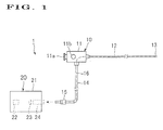
- FIG. 1 is a diagram schematically showing a general construction of an endoscope device according to one embodiment of the present invention;
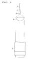
- FIG. 2 is a sectional view showing an essential part of the above endoscope device;
- FIG. 3 is a view showing an optical system of the endoscope device and an optical path passing therethrough; and
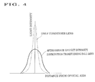
- FIG. 4 is a graph in which an intensity distribution of a flux of light at the focus of a ball lens for transforming a light intensity distribution is indicated by a solid line and an intensity distribution at the focus of a condenser lens in absence of the ball lens is indicated by an imaginary line.
-
- One embodiment of the present invention will now be described with reference to the accompanying drawings.
- FIG. 1 shows an
endoscope device 1. Theendoscope device 1 includes anendoscope 10 and alight source device 20 for supplying an illumination light to theendoscope 10. - The
light source device 20 includes ahousing 21. Received in thehousing 21 are alight source 22, acondenser lens 23 and alight guide connector 24. Thosecomponents 22 through 24 received in thehousing 21 are linearly arranged along an optical axis of the illumination light coming from thelight source 22. A diaphragm 25 (see FIG. 2) is provided between thecondenser lens 23 and thelight guide connector 24. Since thelight guide connector 24 includes an essential part of the present invention, it will be described in more detail later. - The
endoscope 10 includes amain body portion 11, aflexible insertion portion 12 extending from themain body portion 11 and atip component portion 13 disposed at a tip of thisinsertion portion 12. Theinsertion portion 12 and thetip component portion 13 are widthwise finely designed so that they can be inserted into a blood vessel, for example. - The
main body portion 11 is provided with an observingocular portion 11a and acontrol knob 11b for bending the insertion portion. A distal end of alight guide cable 14 is connected to themain body portion 11. Alight guide plug 15 is attached to a basal end of thelight guide cable 14. Thislight guide plug 15 is removably connected to thelight guide connector 24. Since thelight guide plug 15 includes an essential part of the present invention, it will be described in more detail later. - The light guide plug 15, the
light guide cable 14, themain body 11, theinsertion portion 12 and thetip component portion 13 receive therein alight guide 16 which is composed of a flux of optical fibers (or single optical fiber). Thelight guide 16 is adapted to introduce the illumination light coming from thelight source device 20 to an illumination window (not shown) formed in thetip component portion 13. The number of optical fibers, which compose thelight guide 16, limited to small in order to cope with theinsertion portion 12 and thetip component portion 13 which are widthwise finely designed. - Accordingly, an incident end face (basal end face) of the
light guide 16 is size-wise finely designed. In order to surely make incident of the illumination light to the finely designed incident end face, as shown in FIG. 2, a pair ofball lenses 30, 31 (optical elements) is provided on an illumination optical path between thecondenser lens 23 and thelight guide 16. The condensing degree of theball lenses condenser lens 23. The large ball lens 30 (light intensity distribution transforming element) on the side of thecondenser lens 23 is disposed at thelight guide connector 24 and the small ball lens 31 (light arresting element) on the side of thelight guide 16 is disposed at thelight guide plug 15. - The
light guide connector 24 includes a connectormain body 26 attached to thehousing 21 and alens receiving member 27 threadingly engaged with thecondenser lens 23 side of theconnector body 26. Thosecomponents Heat radiation fins components - A
plug insertion hole 26a for thelight guide plug 15 is formed in the connectormain body 26. Alens receiving hole 27a (transforming element receiving hole), which is coaxially continuous with theplug insertion hole 26a, is formed in thelens receiving member 27. The light intensity distribution transformingball lens 30 is received in thislens receiving hole 27a. - The inside diameter of the
lens receiving hole 27a is dimensioned large enough to allow the thermal expansion of theball lens 30. In thelens receiving hole 27a, alens retaining potion 27b (transforming element retaining portion) is provided at an inner peripheral edge on thecondenser lens 23 side, and a coiled spring 32 (transforming element biasing means) is received in an area more on theplug insertion hole 26a side than theball lens 30. This coiledsprings 32 urges theball lens 30 against thelens retaining portion 27b. By this, theball lens 30 is fixed without swaying. - The
light guide plug 15 includes a plugmain body 17 and aplug cap 18 threadingly engaged with an end portion of this plugmain body 17. Aguide receiving hole 17a is formed in the plugmain body 17. An incident end portion of thelight guide 16 is received in thisguide receiving hole 17a. Alens receiving hole 18a (arresting element receiving hole), which is coaxially continuous with theguide receiving hole 17a, is formed in theplug cap 18. The optical arrestingball lens 31 is received in thislens receiving hole 18a. An incident end face of thelight guide 16 is correctly positioned on thisball lens 31. - The inside diameter of the
lens receiving hole 18a is dimensioned large enough to allow the thermal expansion of theball lens 31. Alens retaining portion 18b (arresting element retaining portion) is disposed at an inner periphery on the tip side of thelens receiving hole 18a. A resin-made resilient ring 19 (arresting element biasing means) is sandwiched between theplug cap 18 and a distal end face of the plugmain body 17. Thisresilient ring 19 urges theball lens 31 against thelens retaining portion 18b. By this, theball lens 31 is fixed without swaying. - A
step 17b is formed on an outer periphery of the plugmain body 17 of thelight guide plug 15. Abutment of thestep portion 17b with astep portion 26b formed on an inner periphery of the connectormain body 26 determines a constant insertion depth of the light guide plug 15 into thelight guide connector 24. By this, a certain degree of positioning accuracy of the light guide plug 15 with respect to thelight guide connector 24 is obtained. In that condition, the pair ofball lenses - Operation will now be described.
- As shown in FIG. 3, the
light source 22 emits an illumination light towards thecondenser lens 23 generally in parallel relation. Thecondenser lens 23 converges this light into a converged flux of light. After passing through thecondenser lens 23, the light is reduced in diameter of the flux of light as it progresses. At the same time, the light is increased in intensity at a central area (nearby area of the optical axis) of the flux of light and decreased in intensity at a peripheral area. Presuming that there is no provision of theball lens 30 of thelight guide connector 24 at the tip of thecondenser lens 23, the central area of the flux of light reaches the peak in intensity at the focus of thecondenser lens 23 as indicated by an imaginary line of FIG. 4. And the intensity of light is rapidly decreased, as it is displaced, even if slightly, from the center. - Actually, the converging flux of light is made incident to the
ball lens 30 of thelight guide connector 24 in the vicinity of the focus of thecondenser lens 23. Thisball lens 30 is lower in condensing degree of light than thecondenser lens 23. Because of this reason, after passing through theball lens 30, the flux of light is transformed such that the intensity distribution is lowered at the central area and raised at the peripheral area as indicated by a solid line of FIG. 4. The diameter of the flux of light is maintained generally in the same dimension as the one when it is contracted. - Thereafter, the light travels towards the
ball lens 31 of thelight guide plug 15. Since thisball lens 31 is sufficiently large in diameter compared with the contracted diameter of the flux of light, it can surely arrest generally the entire light even if the position is slightly displaced with respect to theball lens 30 of thelight guide connector 24. That is, it can surely arrest both the central area and the peripheral area of the flux of light. - The
ball lens 31 converges the arrested flux of light towards thelight guide 16. At that time, even if the center, i.e., optical axis, of the flux of light is displaced from the axis of the incident end portion of thelight guide 16 and only the peripheral area of the flux of light is made incident to thelight guide 16, the intensity of the incident light is sufficiently large. This light is guided bylight guide 16 and emitted through an illumination window formed in thetip component portion 13 so as to hit an object to be observed. By this, it can illuminate the object brightly. - As apparent from the foregoing, since there is no inconvenience for the light to illuminate even if the optical axis is slightly displaced from the axis of the
light guide 16, strict positioning accuracy of thelight guide connector 24 with respect to thelight guide plug 15 is not required. As a result, the user can easily perform the insertion operation of thelight guide plug 15, and convenient efficiency of theendoscope device 1 can be enhanced extensively. - Since the
ball lens 30 of thelight guide connector 24 acts to defocus, uneven intensity of light at a light emitting surface of thelight source 22 can be uniformed. Moreover, the shadow of thediaphragm 25 can be removed. - Since the
ball lens 31 of the light guide plug 15 acts to increase the maximum incident angle of the light directing to thelight guide 16, the maximum outgoing angle from the illumination window is also increased and thus, the range of area for the light to illuminate can be increased. - By using the
ball lenses - Since the
plug cap 18 is threadingly engaged with the plugmain body 15, it can easily be removed. By this, the light distribution characteristic and other characteristics of the illumination can be adjusted optionally by replacing theball lens 31 with one which has a wide variety of specifications.. - The present invention is not limited to the above embodiment, and many changes and modifications can be made. For example, instead of the
ball lenses - It is also accepted that the light source and the condenser lens are integrally formed as a light source unit.
Claims (4)
- An endoscope device(1) comprising:CHARACTERIZED in that said light source device(20) being provided with a light intensity distribution transforming element(30) for transforming intensity distribution of a converging flux of light coming from said condenser lens(23) such that the intensity distribution is lowered at a central area and raised at a peripheral area; and(A) a light source device(20) including a light source(22), a condenser lens(23) for converging an illumination light coming from said light source (22) and a light guide connector(24); and(B) an endoscope(10) including a light guide plug(15) which can be inserted into and removed from said light guide connector(24) and a light guide(16) whose incident end is received in said light guide plug(15);
said light guide plug(15) of said endoscope(10) being provided with a light arresting element(31) for arresting the light coming from said light intensity distribution transforming element(30) and making incidence of such arrested light to an incident end face of said light guide(16) in a state that said light guide plug(15) is inserted in said light guide connector(24). - An endoscope device(1) according to claim 1, wherein said light guide connector(24) includes a plug insertion hole(26a) for said light guide plug(15) and a transforming element receiving hole(27a) continuous with the condenser lens(23) side of said plug insertion hole(26a), and said light intensity distribution transforming element(30) is received in said transforming element receiving hole(27a).
- An endoscope device(1) according to claim 1, wherein said light intensity distribution transforming element(30) and said light arresting element(31) are lenses which are lower in condensing degree of light than said condenser lens(23).
- An endoscope device(1) according to claim 1, wherein said light intensity distribution transforming element(30) and said light arresting element(31) are ball lenses.
Applications Claiming Priority (2)
| Application Number | Priority Date | Filing Date | Title |
|---|---|---|---|
| JP2001331087A JP3805661B2 (en) | 2001-10-29 | 2001-10-29 | Endoscope device |
| JP2001331087 | 2001-10-29 |
Publications (2)
| Publication Number | Publication Date |
|---|---|
| EP1306047A2 true EP1306047A2 (en) | 2003-05-02 |
| EP1306047A3 EP1306047A3 (en) | 2004-01-21 |
Family
ID=19146715
Family Applications (1)
| Application Number | Title | Priority Date | Filing Date |
|---|---|---|---|
| EP02256282A Withdrawn EP1306047A3 (en) | 2001-10-29 | 2002-09-11 | Endoscope |
Country Status (3)
| Country | Link |
|---|---|
| US (1) | US20030083549A1 (en) |
| EP (1) | EP1306047A3 (en) |
| JP (1) | JP3805661B2 (en) |
Cited By (1)
| Publication number | Priority date | Publication date | Assignee | Title |
|---|---|---|---|---|
| FR2864438A1 (en) * | 2003-12-31 | 2005-07-01 | Mauna Kea Technologies | Optical head for confocal imaging system, has ball lens, with large numerical aperture, to converge light beam produced by laser source at excitation point in observed sub-surface field of sample, and unit allowing point to scan field |
Families Citing this family (2)
| Publication number | Priority date | Publication date | Assignee | Title |
|---|---|---|---|---|
| JP5178239B2 (en) * | 2008-02-27 | 2013-04-10 | オリンパスメディカルシステムズ株式会社 | Medical system |
| KR101352960B1 (en) * | 2012-03-15 | 2014-01-22 | 한국광기술원 | Lensed fiber optic probe and Optical Coherence Tomography using the same |
Citations (6)
| Publication number | Priority date | Publication date | Assignee | Title |
|---|---|---|---|---|
| US4483585A (en) * | 1981-12-18 | 1984-11-20 | Olympus Optical Co., Ltd. | Illuminating device having optical light guide formed as fibre bundle |
| US4721359A (en) * | 1984-06-08 | 1988-01-26 | Olympus Optical Co., Ltd. | Illuminating optical system for endoscopes |
| US5800343A (en) * | 1994-08-18 | 1998-09-01 | Fuji Photo Optical Co., Ltd. | Endoscope light guide connector allowing adjustment of the angle of incident light rays |
| JPH10295640A (en) * | 1997-04-22 | 1998-11-10 | Asahi Optical Co Ltd | Lighting system for endoscope |
| US5924978A (en) * | 1995-08-04 | 1999-07-20 | Asahi Kogaku Kogyo Kabushiki Kaisha | Portable endoscope system with a bayonet switching mechanism. |
| WO2000001984A1 (en) * | 1998-07-02 | 2000-01-13 | Ccs Inc. | Lighting device for surface inspection |
Family Cites Families (12)
| Publication number | Priority date | Publication date | Assignee | Title |
|---|---|---|---|---|
| US4222375A (en) * | 1978-03-10 | 1980-09-16 | Miguel Martinez | In vivo illumination system utilizing a cannula with a conical opening allowing a snap-fit with a conical lens and an aperture for flow of fluids and utilizing a housing with a spherical lens for focusing light onto fiber optics |
| JPS60123818A (en) * | 1983-12-08 | 1985-07-02 | Olympus Optical Co Ltd | Optical transmitter |
| US4953937A (en) * | 1988-05-17 | 1990-09-04 | Olympus Optical Co., Ltd. | Illumination optical system |
| US5170454A (en) * | 1989-04-13 | 1992-12-08 | Kabushiki Kaisha Machida Seisakusho | Optical connector for endoscope |
| JPH03118509A (en) * | 1989-10-02 | 1991-05-21 | Olympus Optical Co Ltd | Light source optical system for endoscope |
| JP2591523Y2 (en) * | 1990-10-31 | 1999-03-03 | 株式会社町田製作所 | Connector device for illumination light of endoscope |
| US5754719A (en) * | 1996-11-22 | 1998-05-19 | Cogent Light Technologies, Inc. | Method for coupling light from single fiberoptic to a multi-fiber bundle with enhanced field uniformity and better coupling efficiency |
| JP3865489B2 (en) * | 1997-11-27 | 2007-01-10 | 株式会社町田製作所 | Rigid endoscope |
| JP2000287915A (en) * | 1999-04-08 | 2000-10-17 | Machida Endscope Co Ltd | Guide tube device for surgery |
| US6464633B1 (en) * | 1999-08-23 | 2002-10-15 | Olympus Optical Co., Ltd. | Light source device for endoscope using DMD |
| JP4454078B2 (en) * | 1999-10-08 | 2010-04-21 | 株式会社町田製作所 | Endoscope bending tube and method of manufacturing the same |
| JP4203635B2 (en) * | 1999-10-21 | 2009-01-07 | パナソニック株式会社 | Laser processing apparatus and laser processing method |
-
2001
- 2001-10-29 JP JP2001331087A patent/JP3805661B2/en not_active Expired - Lifetime
-
2002
- 2002-09-11 EP EP02256282A patent/EP1306047A3/en not_active Withdrawn
- 2002-10-10 US US10/268,851 patent/US20030083549A1/en not_active Abandoned
Patent Citations (6)
| Publication number | Priority date | Publication date | Assignee | Title |
|---|---|---|---|---|
| US4483585A (en) * | 1981-12-18 | 1984-11-20 | Olympus Optical Co., Ltd. | Illuminating device having optical light guide formed as fibre bundle |
| US4721359A (en) * | 1984-06-08 | 1988-01-26 | Olympus Optical Co., Ltd. | Illuminating optical system for endoscopes |
| US5800343A (en) * | 1994-08-18 | 1998-09-01 | Fuji Photo Optical Co., Ltd. | Endoscope light guide connector allowing adjustment of the angle of incident light rays |
| US5924978A (en) * | 1995-08-04 | 1999-07-20 | Asahi Kogaku Kogyo Kabushiki Kaisha | Portable endoscope system with a bayonet switching mechanism. |
| JPH10295640A (en) * | 1997-04-22 | 1998-11-10 | Asahi Optical Co Ltd | Lighting system for endoscope |
| WO2000001984A1 (en) * | 1998-07-02 | 2000-01-13 | Ccs Inc. | Lighting device for surface inspection |
Non-Patent Citations (1)
| Title |
|---|
| PATENT ABSTRACTS OF JAPAN vol. 1999, no. 02, 26 February 1999 (1999-02-26) -& JP 10 295640 A (ASAHI OPTICAL CO LTD), 10 November 1998 (1998-11-10) * |
Cited By (1)
| Publication number | Priority date | Publication date | Assignee | Title |
|---|---|---|---|---|
| FR2864438A1 (en) * | 2003-12-31 | 2005-07-01 | Mauna Kea Technologies | Optical head for confocal imaging system, has ball lens, with large numerical aperture, to converge light beam produced by laser source at excitation point in observed sub-surface field of sample, and unit allowing point to scan field |
Also Published As
| Publication number | Publication date |
|---|---|
| JP3805661B2 (en) | 2006-08-02 |
| JP2003126033A (en) | 2003-05-07 |
| US20030083549A1 (en) | 2003-05-01 |
| EP1306047A3 (en) | 2004-01-21 |
Similar Documents
| Publication | Publication Date | Title |
|---|---|---|
| US5042891A (en) | Active device mount assembly with interface mount for push-pull coupling type optical fiber connectors | |
| US4615333A (en) | Rigid endoscope of oblique window type | |
| US6554767B2 (en) | Endoscopic optical adapter freely attachable to and detachable from endoscope | |
| JP4976406B2 (en) | Surgical wide-angle lighting system | |
| US20030216618A1 (en) | Endoscopic light source connector | |
| EP2473128B1 (en) | Illumination device for use in an ophthalmic surgical apparatus | |
| JP2003523539A (en) | Snap-on connector system for coupling light from illuminator to optical fiber | |
| EP3108804A1 (en) | Optical fibre connector device, and endoscope system | |
| US6120161A (en) | Video headlight and cable | |
| US5800343A (en) | Endoscope light guide connector allowing adjustment of the angle of incident light rays | |
| US11452437B2 (en) | Light source apparatus for endoscope, endoscope, and endoscope system | |
| JPS61141351A (en) | Detachable connection mechanism between optical fiber and laser radiation apparatus | |
| EP1306047A2 (en) | Endoscope | |
| WO2015111540A1 (en) | Light source system for endoscope | |
| US5624438A (en) | Retinal wide-angle illuminator for eye surgery | |
| US5196964A (en) | Magnifier | |
| RU2678962C1 (en) | Optical connector, cable and optical communication device | |
| US6374025B1 (en) | Lightguide connector joint in an endoscopic system | |
| US20150241687A1 (en) | Light source device for endoscope system | |
| JP4679198B2 (en) | Endoscope | |
| US10492690B2 (en) | Tip for laser handpiece | |
| US7695202B1 (en) | Visual laser diode to fiber coupling system | |
| US6257741B1 (en) | Lamp assembly for a light source | |
| JP3585653B2 (en) | Illumination light transmission system adapter for endoscope device | |
| JP4040155B2 (en) | Endoscope light source device |
Legal Events
| Date | Code | Title | Description |
|---|---|---|---|
| PUAI | Public reference made under article 153(3) epc to a published international application that has entered the european phase |
Free format text: ORIGINAL CODE: 0009012 |
|
| AK | Designated contracting states |
Designated state(s): AT BE BG CH CY CZ DE DK EE ES FI FR GB GR IE IT LI LU MC NL PT SE SK TR |
|
| AX | Request for extension of the european patent |
Extension state: AL LT LV MK RO SI |
|
| PUAL | Search report despatched |
Free format text: ORIGINAL CODE: 0009013 |
|
| AK | Designated contracting states |
Kind code of ref document: A3 Designated state(s): AT BE BG CH CY CZ DE DK EE ES FI FR GB GR IE IT LI LU MC NL PT SE SK TR |
|
| AX | Request for extension of the european patent |
Extension state: AL LT LV MK RO SI |
|
| AKX | Designation fees paid | ||
| REG | Reference to a national code |
Ref country code: DE Ref legal event code: 8566 |
|
| STAA | Information on the status of an ep patent application or granted ep patent |
Free format text: STATUS: THE APPLICATION IS DEEMED TO BE WITHDRAWN |
|
| 18D | Application deemed to be withdrawn |
Effective date: 20040722 |