EP1302545A2 - Enzyme Biosensor - Google Patents
Enzyme Biosensor Download PDFInfo
- Publication number
- EP1302545A2 EP1302545A2 EP02022418A EP02022418A EP1302545A2 EP 1302545 A2 EP1302545 A2 EP 1302545A2 EP 02022418 A EP02022418 A EP 02022418A EP 02022418 A EP02022418 A EP 02022418A EP 1302545 A2 EP1302545 A2 EP 1302545A2
- Authority
- EP
- European Patent Office
- Prior art keywords
- biosensor
- substrate
- cover
- microstructures
- channel
- Prior art date
- Legal status (The legal status is an assumption and is not a legal conclusion. Google has not performed a legal analysis and makes no representation as to the accuracy of the status listed.)
- Granted
Links
Images


Classifications
-
- C—CHEMISTRY; METALLURGY
- C12—BIOCHEMISTRY; BEER; SPIRITS; WINE; VINEGAR; MICROBIOLOGY; ENZYMOLOGY; MUTATION OR GENETIC ENGINEERING
- C12Q—MEASURING OR TESTING PROCESSES INVOLVING ENZYMES, NUCLEIC ACIDS OR MICROORGANISMS; COMPOSITIONS OR TEST PAPERS THEREFOR; PROCESSES OF PREPARING SUCH COMPOSITIONS; CONDITION-RESPONSIVE CONTROL IN MICROBIOLOGICAL OR ENZYMOLOGICAL PROCESSES
- C12Q1/00—Measuring or testing processes involving enzymes, nucleic acids or microorganisms; Compositions therefor; Processes of preparing such compositions
- C12Q1/001—Enzyme electrodes
- C12Q1/004—Enzyme electrodes mediator-assisted
-
- G—PHYSICS
- G01—MEASURING; TESTING
- G01N—INVESTIGATING OR ANALYSING MATERIALS BY DETERMINING THEIR CHEMICAL OR PHYSICAL PROPERTIES
- G01N27/00—Investigating or analysing materials by the use of electric, electrochemical, or magnetic means
- G01N27/26—Investigating or analysing materials by the use of electric, electrochemical, or magnetic means by investigating electrochemical variables; by using electrolysis or electrophoresis
- G01N27/28—Electrolytic cell components
- G01N27/30—Electrodes, e.g. test electrodes; Half-cells
- G01N27/327—Biochemical electrodes, e.g. electrical or mechanical details for in vitro measurements
- G01N27/3271—Amperometric enzyme electrodes for analytes in body fluids, e.g. glucose in blood
- G01N27/3272—Test elements therefor, i.e. disposable laminated substrates with electrodes, reagent and channels
-
- Y—GENERAL TAGGING OF NEW TECHNOLOGICAL DEVELOPMENTS; GENERAL TAGGING OF CROSS-SECTIONAL TECHNOLOGIES SPANNING OVER SEVERAL SECTIONS OF THE IPC; TECHNICAL SUBJECTS COVERED BY FORMER USPC CROSS-REFERENCE ART COLLECTIONS [XRACs] AND DIGESTS
- Y10—TECHNICAL SUBJECTS COVERED BY FORMER USPC
- Y10T—TECHNICAL SUBJECTS COVERED BY FORMER US CLASSIFICATION
- Y10T29/00—Metal working
- Y10T29/49—Method of mechanical manufacture
- Y10T29/49002—Electrical device making
Definitions
- the present invention is directed to physical structures and methods for controlling the flow of small volumes of liquids through a biosensor. More particularly, the present invention is directed to such physical structures that define a capillary channel and microstructures.
- Electrochemical biosensors are known. They have been used to determine the concentration of various analytes from biological samples, particularly from blood. Electrochemical biosensors are described in U.S. Patent Nos. 5,413,690; 5,762,770; 5,798,031; and 5,997,817 the disclosure of each of which is expressly incorporated herein by reference.
- a biosensor comprising a substrate and a cover extending across at least a portion of the substrate.
- the cover includes a first surface facing the substrate and a second surface. At least a portion of the first surface is removed to define a capillary channel.
- the capillary channel has a surface energy ranging from about 60 mN/m to about 72 mN/m.
- a biosensor comprises a capillary path defined between a substrate and a cover and at least one microstructure positioned in the capillary path.
- the at least one microstructure includes a fixed end coupled to either the substrate or the cover and an opposite free end, wherein the free end is metallic.
- a biosensor comprising a substrate, electrodes positioned on the substrate, a cover extending across at least a portion of the substrate to define a capillary path, and at least one microstructure positioned in the capillary path.
- the at least one microstructure includes a fixed end coupled to the cover and an opposite free end, wherein the free end is metallic.
- a method of forming biosensor comprises the steps of providing a substrate, a reagent for the measurement of at least one analyte, and a cover, the cover including a first surface, exposing the cover to at least one pulse of light of sufficient to ablate the first surface in a pre-determined pattern creating a channel, cleaning the first surface of the cover so that the surface energy of the channel ranges from about 60 mN/m to about 72 mN/m, and placing the first surface of the cover upon the substrate to define a capillary path and the reagent is positioned in the capillary path.
- the present invention relates to a biosensor and method of manufacturing a biosensor that is formed to provide a well-controlled fluid flow and simultaneously reduce the volume of liquid sample required for testing.
- Biosensors can take the form of any number of diagnostic biosensors including, for example, electrochemical and photometric biosensors. Aspects of the invention are presented in Figs. 1-11, which are not drawn to scale and wherein like components in the several views are numbered alike.
- analyte refers to the molecule or compound to be quantitatively determined.
- Non-limiting examples of analytes include carbohydrates, proteins, such as hormones and other secreted proteins, enzymes, and cell surface proteins; glycoproteins; peptides; small molecules; polysaccharides; antibodies (including monoclonal or polyclonal Ab); nucleic acids; drugs; toxins; viruses of virus particles; portions of a cell wall; and other compounds processing epitopes.
- the analyte of interest preferably comprises glucose.
- Biosensor 10 has an electrode-support substrate 12, an electrical conductor 14 positioned on the substrate 12 that is disrupted to define electrodes 16, 18, and a cover substrate 20 positioned on substrate 12.
- Biosensor 10 is in the form of a disposable test strip. It is appreciated however, that biosensor 10 can assume any number of forms and shapes in accordance with this disclosure.
- Biosensor 10 is preferably produced from rolls of material however, it is understood that biosensor 10 can be constructed from individual sheets in accordance with this disclosure. Thus, when biosensors 10 are produced from rolls, the selection of materials necessitates the use of materials that are sufficiently flexible for roll processing, but which are still rigid enough to give a useful stiffness to finished biosensor 10.
- the electrode-support substrate 12 includes a first surface 22 and a second surface 24.
- substrate 12 has opposite first and second ends 26, 28 and opposite edges 30, 32 extending between the first and second ends 26, 28.
- Substrate 12 is generally rectangular in shape, it is appreciated however, that support 12 may be formed in a variety of shapes and sizes in accordance with this disclosure.
- Substrate 12 may be constructed from a wide variety of insulative materials. Non-limiting examples of insulative materials that provide desirable electrical and structural properties include glass, ceramics, vinyl polymers, polyimides, polyesters, and styrenics.
- substrate 12 is a flexible polymer, such as a polyester or polyimide.
- a non-limiting example of a suitable material is 5 mil (125 ⁇ m) thick KALADEX®, a polyethylene naphthalate film commercially available from E.I. DuPont de Nemours, Wilmington, Delaware, which is coated with gold by: ROWO Coatings, Herbolzheim, Germany.
- Electrodes 16, 18 are created or isolated from conductor 14 on first surface 22 of electrode-support substrate 12. Electrodes 16, 18 are isolated from conductor 14 by gaps 66. See Fig. 4. It is also appreciated that electrodes 16, 18 can be formed from multiple layers of same or different electrically conductive materials.
- Non-limiting examples of a suitable electrical conductor 14 include aluminum, carbon (such as graphite), cobalt, copper, gallium, gold, indium, iridium, iron, lead, magnesium, mercury (as an amalgam), nickel, niobium, osmium, palladium, platinum, rhenium, rhodium, selenium, silicon (such as highly doped polycrystalline silicon), silver, tantalum, tin, titanium, tungsten, uranium, vanadium, zinc, zirconium, mixtures thereof, and alloys, oxides, or metallic compounds of these elements.
- electrical conductor 14 is selected from the following materials: gold, platinum, palladium, iridium, or alloys of these metals, since such noble metals and their alloys are unreactive in biological systems. Most preferably, electrical conductor 14 is gold.
- Electrodes 16, 18 are isolated from the rest of the electrical conductor 14 by laser ablation. Techniques for forming electrodes on a surface using laser ablation are known. See, for example, U.S. Patent Application Serial No. 09/411,940 (published as WO 01/25775), titled “Laser Defined Features for Patterned Laminates and Electrodes", the disclosure of which is expressly incorporated herein by reference.
- electrodes 16, 18 are created by removing the electrical conductor 14 from an area extending around the electrodes to form a gap of exposed support substrate 12.
- electrodes 16, 18 are isolated from the rest of the electrically-conductive material on substrate 12 by a gap having a width of about 25 ⁇ m to about 500 ⁇ m, preferably the gap has a width of about 100 ⁇ m to about 200 ⁇ m.
- electrodes 16, 18 may be created by laser ablation alone on substrate 12.
- electrodes 16, 18 cooperate with one another to define an electrode array 34.
- electrodes 16, 18 each include a contact 36 and a lead 38 extending between the contact 34 and the array 36.
- the leads 38 extending from the array 34 can be formed to have many lengths and extend to a variety of locations on the electrode-support substrate 12. It is appreciated that the configuration of the electrode array, the number of electrodes, as well as the spacing between the electrodes may vary in accordance with this disclosure and that a greater than one array may be formed as will be appreciated by one of skill in the art.
- a recess 40 is formed through the electrical conductor 14 and a portion of the first surface 22 of the support substrate 12 by laser ablation using techniques as described above.
- the recess 40 extends from end 26 of the substrate 12 to the electrode array 34.
- the recess 40 is defined further by walls 44. See Fig. 2B. It is appreciated that the amount of the support substrate 12 that is removed can vary in accordance with the present disclosure. It is also appreciated that substrate 12 of biosensor 10 can be formed without a recess in accordance with the present disclosure.
- the recess 40 includes a plurality of microstructures 42 extending from the first surface 22 of the support substrate 12.
- the microstructures 42 are spaced-apart from one another, on a nearest neighbor basis, by a first distance that is less than the distance necessary to achieve capillary flow of liquid between the microstructures.
- Microstructures 42 are formed as posts that extend away from the substrate through the recess 40. See Fig. 3.
- Each microstructure 42 includes a fixed end 78 coupled to the substrate 12 and an opposite free end 80. Free end 80 exposed in channel 40 is metallic-coated.
- the substrate 12 is also cleaned, removing polymeric debris and other organic material and increasing the surface energy of surfaces of both the surface of the channel 40 and the microstructures 42.
- the microstructures 42 can assume a variety of shapes and sizes in accordance with the present disclosure.
- the recess 40 includes six rows of sixteen microstructures 42. The number and location of microstructures 42 depend upon the size of biosensor 10.
- the recess 40 may in fact be formed without microstructures in accordance with the present disclosure.
- the microstructures 42 may be positioned in a variety of locations in the recess 40. Although not shown, at least some of the microstructures can be joined to the walls 44 (Fig. 1) of the recess 40.
- the cover substrate 20 is coupled to the electrode-support substrate 12 adjacent to the first end 26. See Fig. 1.
- the cover substrate 20 of biosensor 10 includes a first surface 46 facing substrate 12 and an opposite second surface 48. See Fig. 3.
- cover substrate 20 has opposite first and second ends 50, 52 and edges 54, 56 extending between ends 50, 52. Openings 58 extend between first and second surfaces 46, 48 and through any material coating either surface 46, 48.
- openings 58 are offset from array 34. See, Fig. 1. It is appreciated, however, that any number of openings 58 can be located in a number of locations and take on a variety of shapes and sizes in accordance with this disclosure.
- the cover substrate 20 is formed of a flexible polymer and preferably from a polymer such as polyester.
- the first surface 46 of the cover substrate 20 is coated with a metallic material 88 and preferably with a metal such as gold, platinum, palladium, and iridium.
- the cover substrate 20 is 3 mil (75 ⁇ m) Clear PEN film named KALADEX by DuPont and gold coated by: ROWO Coatings, Herbolzheim, Germany.
- the cover substrate 20 is formed to include a capillary channel 60 and secondary capillary recesses 86 spaced-apart from channel 60. See Fig. 5.
- the capillary channel 60 is formed to provide a well-controlled fluid flow and simultaneously reduce the volume of liquid required in biosensor 10. As shown in Fig. 5, the capillary channel 60 extends between first and second ends 50, 52 and is defined by interior borders 64.
- the secondary capillary recesses 86 also extend between first and second ends 50, 52 and are defined by inner and outer borders 90, 92.
- the capillary channel 60 and secondary capillary recesses 86 are formed through at least the material 88 and preferably through a portion of the first surface 46 (Fig. 3) of the cover substrate 20 by laser ablation using techniques as described above. It is appreciated that the amount of the cover substrate 20 that is removed can vary in accordance with the present disclosure.
- the capillary channel 60 includes a plurality of microstructures 62.
- the microstructures 62 are spaced-apart from one another, on a nearest neighbor basis, by a first distance that is less than the distance necessary to achieve capillary flow of liquid between the microstructures.
- the capillary channel 60 illustrated in Fig. 5 includes sixteen rows of sixteen microstructures 62. The number and location of microstructures 62 depend upon the size of biosensor.
- Microstructures 62 shown in Fig. 5 are formed as generally square-shaped posts. It is appreciated, however, that microstructures can have a variety of shapes and sizes, non-limiting examples of which are illustrated in Figs. 6-8 and 11, in accordance with this disclosure.
- Microstructures 62 extend away from the cover substrate 20 into the capillary channel 60. See Fig. 5. Each microstructure 62 includes a fixed end 96 coupled to the cover substrate 20 and an opposite free end 98. The cover substrate 20 is also cleaned, removing polymeric debris and other organic material present and increasing the surface energy of surfaces of both the surface of the channel 60 and the microstructures 42. It is also appreciated that the microstructures 62 may be positioned in a variety of locations in the channel 60 as discussed above with reference to microstructures 42.
- Channel 60 has a height of about 1 ⁇ m to about 60 ⁇ m, preferably 2 ⁇ m to about 30 ⁇ m, and most preferably about 5 ⁇ m to about 15 ⁇ m.
- the width of channel 60 between interior borders 64 is about 1 mm to about 4 mm, preferably 1.5 mm to about 3.0 mm, most preferably about 2.0 mm to about 2.5 mm.
- the channel 60 and the recess 40 cooperate to define a capillary path. It is appreciated that when the substrate 12 does not include the recess 40, the channel 60 itself will define the capillary path.
- the capillary path is illustratively straight, the capillary path may be curved and/or include turns.
- each sealed portion 82 has an interior border that lies in general alignment with secondary capillary recesses 86 and an exterior border.
- the exterior border of each sealed portion 82 lies in general alignment with a respective edge 54, 56 of the electrode-support substrate 12.
- the cover substrate 20 is coupled to the support substrate 12 by a liquid adhesive.
- a liquid adhesive is EPO-TEK OH100-4 commercially available from Epoxy Technology, Billerica, MA.
- a heated tool is applied on the area where bonding is to take place to promote fast curing.
- the cover substrate 20 may be coupled to the support substrate 12 using a wide variety of commercially available adhesives as well as heat sealing, or ultrasonic methods of joining the cover substrate 20 and support substrate 12 together in accordance with this disclosure.
- a reagent 68 is positioned on the array 36.
- the reagent 68 provides electrochemical probes for specific analytes. It is appreciated, however, that reagent 68 can also be formed for use in a photometric biosensor.
- biosensor is a photometric biosensor, other aspects of the biosensor construction will change to accommodate photometric measurements. Such a construction is well known in the art.
- the choice of the specific reagent 68 depends on the specific analyte or analytes to be measured, and are well known to those of ordinary skill in the art.
- An example of a reagent that may be used in biosensor 10 of the present invention is a reagent for measuring glucose from a whole blood sample.
- a non-limiting example of a reagent for measurement of glucose in a human blood sample contains 62.2 mg polyethylene oxide (mean molecular weight of 100-900 kilo Daltons), 3.3 mg NATROSOL 244M, 41.5 mg AVICEL RC-591 F, 89.4 mg monobasic potassium phosphate, 157.9 mg dibasic potassium phosphate, 437.3 mg potassium ferricyanide, 46.0 mg sodium succinate, 148.0 mg trehalose, 2.6 mg TRITON X-100 surfactant, and 2,000 to 9,000 units of enzyme activity per gram of reagent.
- the enzyme is prepared as an enzyme solution from 12.5 mg coenzyme PQQ and 1.21 million units of the apoenzyme of quinoprotein glucose dehydrogenase. This reagent is further described in U.S. Patent No. 5,997,817, the disclosure of which is expressly incorporated herein by reference.
- Non-limiting examples of enzymes and mediators that may be used in measuring particular analytes in biosensor 10 are listed below in Table 1.
- Analyte Enzymes Mediator Additional Mediator (Oxidized Form) Glucose Glucose Dehydrogenase Ferricyanide and Diaphorase Glucose Glucose-Dehydrogenase Ferricyanide (Quinoprotein) Cholesterol Cholesterol Esterase and Ferricyanide 2,6-Dimethyl-1,4- Cholesterol Oxidase Benzoquinone 2,5-Dichloro-1,4- Benzoquinone or Phenazine Ethosulfate HDL Cholesterol Esterase Ferricyanide 2,6-Dimethyl-1,4- Cholesterol and Cholesterol Oxidase Benzoquinone 2,5-Dichloro-1,4- Benzoquinone or Phenazine Ethosulfate Triglycerides Lipoprotein Lipase, Ferr
- At least one additional enzyme is used as a reaction catalyst.
- some of the examples shown in Table 1 may utilize an additional mediator, which facilitates electron transfer to the oxidized form of the mediator.
- the additional mediator may be provided to the reagent in lesser amount than the oxidized form of the mediator.
- a plurality of biosensors 10 are typically packaged in a vial, usually with a stopper formed to seal the vial. It is appreciated, however, that biosensors 10 may be packaged individually, or biosensors can be folded upon one another, rolled in a coil, stacked in a cassette magazine, or packed in blister packaging.
- Biosensor 10 is used in conjunction with the following:
- the meter will normally be adapted to apply an algorithm to the current measurement, whereby an analyte concentration is provided and visually displayed. Improvements in such power source, meter, and biosensor system are the subject of commonly assigned U.S. Pat. No. 4,963,814, issued Oct. 16, 1990; U.S. Pat. No. 4,999,632, issued Mar. 12, 1991; U.S. Pat. No. 4,999,582, issued Mar. 12, 1991; U.S. Pat. No. 5,243,516, issued Sep. 7, 1993; U.S. Pat. No. 5,352,351, issued Oct. 4, 1994; U.S. Pat. No. 5,366,609, issued Nov. 22, 1994; White et al., U.S. Pat. No. 5,405,511, issued Apr. 11, 1995; and White et al., U.S. Pat. No. 5,438,271, issued Aug. 1, 1995, the disclosures of each of which are expressly hereby incorporated by reference.
- fluid samples may be analyzed.
- human body fluids such as whole blood, plasma, sera, lymph, bile, urine, semen, cerebrospinal fluid, spinal fluid, lacrimal fluid and stool specimens as well as other biological fluids readily apparent to one skilled in the art may be measured.
- Fluid preparations of tissues can also be assayed, along with foods, fermentation products and environmental substances, which potentially contain environmental contaminants.
- whole blood is assayed with this invention.
- biosensor 10 is manufactured by feeding a roll of metallized electrode support material through guide rolls 70 into a first ablation station 72 as shown by arrow 74.
- a laser system capable of ablating support 12 is known to those of ordinary skill in the art. Non-limiting examples of which include excimer lasers, with the pattern of ablation controlled by mirrors, lenses, and masks.
- a non-limiting example of such a custom fit system is the LPX-300 or LPX-200 both commercially available from LPKF Laser Electronic GmbH, of Garbsen, Germany, equipped with a 248 nm wavelength excimer laser. It is appreciated that higher wavelength UV lasers can, however, be used in accordance with this disclosure.
- the metallic layer of the metallized film is ablated in a pre-determined pattern, to form a ribbon of isolated electrode sets on the electrode support material.
- 90 mJ/cm 2 energy is applied to ablate electrodes 16, 18 isolated by gaps 66 in 50 nm thick gold conductor 14, 90 mJ/cm 2 energy is applied. It is appreciated, however, that the amount of energy required may vary from material to material, metal to metal, or thickness to thickness.
- the ribbon is then passed through more guide rolls, with a tension loop and through an optional inspection system where both optical and electrical inspection can be made. The system is used for quality control in order to check for defects.
- the ribbon is fed, as shown by arrow 76 into a second laser ablation station 100.
- Station 100 is similar to station 72.
- the first surface 22 of the support substrate 12 is ablated in a pre-determined pattern, to form the recess 40 extending about the microstructures 42.
- multi-pulses of the laser light are applied. In preferred embodiments, three to five pulses of laser light (90 mJ/cm 2 in each pulse) are applied. It is appreciated the depth of ablation into the surface 22 can vary. Moreover, it is appreciated that the number of pulses applied will very depending upon the polymer and the depth of ablation.
- the number of pulses will increase (a non-limiting example of which is 25 pulses) and as the hardness of polymer decreases, the number of pulses necessary to ablate the surface 22 decreases.
- any seed layer or other metallic layer such as Chromium or Titanium or any other metal is used for any purpose, and then gold is put down on top of the seed layer or other metallic layer, the total thickness of all composite metals is still preferred to be 50 nm. It is appreciated, however, if the total thickness is higher, a higher energy laser will be needed.
- the ablated material that is in either roll form or that has been cut into cards is fed as shown by arrow 101 to a microwave plasma machine 111, a custom-fit equipment, which is commercially available from TePla AG, Kircheim, Germany.
- the ablated material is cleaned by the microwave plasma machine to remove polymeric debris and other organic material and to increase the hydrophilicity of the channel 40 and microstructures 42.
- the surface energy of recess 42 as well as the surface 14 before treatment with the plasma machine is approximately 41mN/m.
- the surface energy after the treatment is approximately 72 mN/m.
- the metallized film is fed as shown by arrow 103 into a reagent dispensing station 104.
- Reagents that have been compounded are fed, as shown by arrow 106, into the dispensing station 104 where it is applied in a liquid form in multiple shots to the array 34.
- the reagent can be applied by multi or single dose by a custom fit precision dispensing station available from Fluilogic Systems Oy, Espoo, Finland.
- Reagent application techniques are well known to one of ordinary skill in the art as described in U.S. Patent No. 5,762,770, the disclosure of which is expressly incorporated herein by reference. It is appreciated that reagents may be applied to the array 34 in a liquid or other form and dried or semi-dried onto the array 34 in accordance with this disclosure.
- a roll of metallized film through guide rolls 108 into a third ablation station 110 as shown by arrow 112.
- the station 110 is similar to station 72. It is appreciated that although three laser ablation stations are illustrated and described, that greater or fewer than three stations may be used in accordance with the disclosure.
- the metallized film and first surface 46 of the material is ablated in a pre-determined pattern, to form the capillary channel 60 extending about microstructures 62 and secondary capillary recesses 86.
- multi-pulses of the laser light are applied to ablate channel 60 and recesses 86 in 50 nm thick gold conductor 14 and 4 micrometers into the surface 46.
- three to five pulses of laser light are applied. It is appreciated the depth of ablation into the surface 46 can vary. Moreover, it is appreciated that the number of pulses applied will very depending upon the polymer and the depth of ablation. For example, as the hardness of the polymer increases the number of pulses will increase (a non-limiting example of which is 25 pulses) and as the hardness of polymer decreases, the number of pulses necessary to ablate the surface 46 decreases. If any seed layer or other metallic layer such as Chromium or Titanium or any other metal is used for any purpose, and then gold is put down on top of the seed layer or other metallic layer, the total thickness of all composite metals is still preferred to be 50 nm. It is appreciated, however, if the total thickness is higher, a higher energy laser will be needed.
- the ablated material that is in either roll form or that has been cut into cards is fed as shown by arrow 105 to the microwave plasma machine 111.
- a second plasma machine could also be used in accordance with this invention. Cleaning with the plasma machine 111 results in the removal of polymeric debris and other organic materials and increased surface energy, making the surfaces very hydrophilic, which helps increase the blood flow rate and fluid spreading.
- the surface energy of the capillary channel 60 as well as the surface 46 before treatment with the plasma machine is approximately 41mN/m.
- the surface energy after the treatment is approximately 72 mN/m.
- the film Upon leaving the microwave plasma machine 111, the film is then fed as shown by arrow 114 into a sensor lamination and cut/pack station 116. At the same time, the reagent-coated film is fed, as shown by arrow 118 into the station 116.
- the cover support material is punched to form openings 58.
- the first surface 46 of the cover support material is then applied to the electrode-support substrate material over the electrode arrays 34.
- a liquid adhesive is dispensed, as shown by arrow 120 through openings 58 of the cover substrate material in the station 116.
- a heated tool is applied on the area where bonding is to take place to promote fast curing of the adhesive between isolated gold surfaces 46 and 14.
- the resulting assembled material is cut to form individual biosensors 10, which are sorted and packed into vials, each closed with a stopper, to give packaged biosensor strips as shown by arrow 122.
- a user of biosensor 10 places a finger having a blood collection incision against ends 26, 50 adjacent to openings of recess 40 and channel 60. See, Fig. 3.
- Capillary forces pull a liquid sample flowing from the incision through the capillary channel 60 across the reagent 68 and the array 36.
- the liquid sample dissolves the reagent 68 and engages the array 36 where the electrochemical reaction takes place.
- a power source e.g., a battery
- a potential difference between the electrodes 16, 18.
- the current measuring meter measures the diffusion-limited current generated by the oxidation of the reduced form of the mediator at the surface of the working electrode as described above.
- the measured current may be accurately correlated to the concentration of the analyte in sample when the following requirements are satisfied:
- a cover substrate 220 is provided in accordance with the present disclosure.
- Cover substrate 220 is shown in Fig. 6 and is suitable for use with the electrode-support substrate 12.
- the cover substrate 220 is coupled to the electrode-support substrate 12 adjacent to the first end 26.
- the cover substrate 220 is formed of a flexible polymer coated with a metallic material similar to cover substrate 20.
- the cover substrate 220 is formed to include a capillary channel 260 and secondary capillary recesses 86 spaced-apart from channel 260. Like channel 60 in cover 20, the capillary channel 260 is also formed to provide a well controlled fluid flow and simultaneously reduce the volume of liquid required when it cooperates with support substrate 12 in a biosensor.
- the capillary channel 260 and secondary capillary recesses 86 are formed through at least the material 88 and preferably through a portion of the first surface 46 of the cover substrate 220 by laser ablation using techniques as described above. It is appreciated that the amount of the cover substrate 220 that is removed can vary in accordance with the present disclosure.
- the capillary channel 260 includes a plurality of microstructures 262.
- the microstructures 262 are spaced-apart from one another, on a nearest neighbor basis, by a first distance that is less than the distance necessary to achieve capillary flow of liquid between the microstructures. It is appreciated that the capillary channel 260 can include greater or fewer than the illustrated microstructures in accordance with this disclosure.
- Microstructures 262 are formed as generally round-shaped posts. It is appreciated, however, that microstructures can have a variety of shapes and sizes in accordance with this disclosure.
- the cover substrate 220 is also cleaned, as described above with reference to cover 20, increasing the surface energy of surfaces of both the surface of the channel 40 and the microstructures 42.
- a cover substrate 320 is provided in accordance with the present disclosure.
- Cover substrate 320 is shown in Fig. 7 and is suitable for use with the electrode-support substrate 12.
- the cover substrate 320 is coupled to the electrode-support substrate 12 adjacent to the first end 26.
- the cover substrate 320 is formed of a flexible polymer coated with a metallic material similar to cover substrate 20.
- the cover substrate 320 is formed to include a capillary channel 360 and secondary capillary recesses 86 spaced-apart from channel 360. Like channel 60 in cover 20, the capillary channel 360 is also formed to provide a well controlled fluid flow and simultaneously reduce the volume of liquid required when it cooperates with support substrate 12 in a biosensor.
- the capillary channel 360 and secondary capillary recesses 86 are formed through at least the material 88 and preferably through a portion of the first surface 46 of the cover substrate 320 by laser ablation using techniques as described above. It is appreciated that the amount of the cover substrate 320 that is removed can vary in accordance with the present disclosure. Further, the cover substrate 320 is also cleaned, as described above with reference to cover 20, increasing the surface energy of the surface of the channel 360.
- a cover substrate 420 is provided in accordance with the present disclosure.
- Cover substrate 420 is shown in Fig. 8 and is suitable for use with the electrode-support substrate 12.
- the cover substrate 420 is coupled to the electrode-support substrate 12 adjacent to the first end 26.
- the cover substrate 420 is formed of a flexible polymer coated with a metallic material similar to cover substrate 20.
- the cover substrate 420 is formed to include a capillary channel 460 and secondary capillary recesses 86 spaced-apart from channel 460. Like channel 60 in cover 20, the capillary channel 460 is also formed to provide a well controlled fluid flow and simultaneously reduce the volume of liquid required when it cooperates with support substrate 12 in a biosensor.
- the capillary channel 460 and secondary capillary recesses 86 are formed through at least the material 88 and preferably through a portion of the first surface 46 of the cover substrate 420 by laser ablation using techniques as described above. It is appreciated that the amount of the cover substrate 420 that is removed can vary in accordance with the present disclosure.
- the capillary channel 460 includes a plurality of microstructures 462.
- the microstructures 462 are spaced-apart from one another, on a nearest neighbor basis, by a first distance that is less than the distance necessary to achieve capillary flow of liquid between the microstructures.
- the capillary channel 460 includes five rows of microstructures 462. It is appreciated that the capillary channel 460 can include greater or fewer than the illustrated microstructures in accordance with this disclosure.
- Microstructures 462 are formed as generally bar-shaped posts. It is appreciated, however, that microstructures can have a variety of shapes and sizes in accordance with this disclosure.
- the cover substrate 420 is also cleaned, as described above with reference to cover 20, increasing the surface energy of surfaces of both the surface of the channel 460 and the microstructures 462.
- biosensor 510 is formed to include an electrode-support substrate 512.
- Substrate 512 is formed in a similar manner to substrate 12, except that the electrode array 34 is spaced-apart from first end 26 and a recess 540 including microstructures 42 extends between end 26 and array 34.
- the recess is formed through the electrical conductor 14 and a portion of the first surface 22 of the support substrate 512 by laser ablation using techniques as described above. It is appreciated that the amount of the support substrate 512 that is removed can vary in accordance with the present disclosure. It is also appreciated that substrate 512 of biosensor 510 can be formed without a recess in accordance with the present disclosure. It is also appreciated that the microstructures 42 can assume a variety of shapes and sizes in accordance with the present disclosure.
- the cover substrate 520 is coupled to the electrode-support substrate 12 adjacent to the first end 26. See Fig. 10.
- the cover substrate 520 is formed of materials similar to the cover substrate 20 as described above.
- the cover substrate 520 is formed to include a capillary channel 560 and secondary capillary recesses 86 spaced-apart from channel 560.
- the capillary channel 560 is formed to provide a well-controlled fluid flow and simultaneously reduce the volume of liquid required in biosensor 510.
- the capillary channel 560 extends between first and second ends 50, 52 and is defined by interior borders 64.
- the capillary channel 560 and secondary capillary recesses 86 are formed through at least the material 88 and preferably through a portion of the first surface of the cover substrate 20 by laser ablation using techniques as described above. It is appreciated that the amount of the cover substrate 520 that is removed can vary in accordance with the present invention.
- the capillary channel 560 includes microstructures 62 that are formed as described above with reference to biosensor 10. It is appreciated that the microstructures 62 can assume a variety of shapes and sizes the number and location of microstructures 62 depend upon the size of biosensor in accordance with the present disclosure.
- the cover substrate 520 is formed to include an inlet 522 that extends between first and second surfaces 46, 48 in the capillary channel 560.
- the inlet 522 is offset from the array 34. See, Fig. 10. It is appreciated, however, that inlet 522 can be located in a number of locations in the channel 560 in accordance with this disclosure, a non-limiting example of which includes the inlet 522 intersecting end 50 of cover substrate 520.
- Biosensor 510 is manufactured in a manner similar to biosensor 10 as described above. Recess 540 of the biosensor 510 is formed in the second laser ablation station 100 by ablating the first surface 22 in a pre-defined pattern to form the recess 540 extending between end 26 and the array 36. The hydrophilicity of the channel 540 and microstructures 42 are increased due to cleaning by a plasma machine 111 as described above with reference to biosensor 10.
- Capillary channel 560 is formed in the cover substrate material in the third ablation station 110 as described above with reference to biosensor 10.
- the ablated material is cleaned by the plasma machine 111 to remove polymeric debris and other organic materials and increasing the hydrophilicity of the channel 560 and microstructures 62.
- the film is then fed into the sensor lamination and cut/pack station 116 where openings 58 and inlet 522 are punched.
- biosensor 10 As described above with reference to biosensor 10, a liquid adhesive is dispensed, through openings 58 of the cover substrate material and a heated tool is applied on the area where bonding is to take place to promote fast curing of the adhesive. The resulting assembled material is cut to form individual biosensors 510, which are sorted and packed into vials, each closed with a stopper, to give packaged biosensor strips.
- the biosensor 510 is used in a manner similar to biosensor 10 as described above.
Abstract
Description
- The present invention is directed to physical structures and methods for controlling the flow of small volumes of liquids through a biosensor. More particularly, the present invention is directed to such physical structures that define a capillary channel and microstructures.
- Electrochemical biosensors are known. They have been used to determine the concentration of various analytes from biological samples, particularly from blood. Electrochemical biosensors are described in U.S. Patent Nos. 5,413,690; 5,762,770; 5,798,031; and 5,997,817 the disclosure of each of which is expressly incorporated herein by reference.
- According to the present invention a biosensor is provided. The biosensor comprises a substrate and a cover extending across at least a portion of the substrate. The cover includes a first surface facing the substrate and a second surface. At least a portion of the first surface is removed to define a capillary channel. The capillary channel has a surface energy ranging from about 60 mN/m to about 72 mN/m.
- According to another aspect of the invention a biosensor is provided. That biosensor comprises a capillary path defined between a substrate and a cover and at least one microstructure positioned in the capillary path. The at least one microstructure includes a fixed end coupled to either the substrate or the cover and an opposite free end, wherein the free end is metallic.
- According to still another aspect of the present invention a biosensor is provided. The biosensor comprises a substrate, electrodes positioned on the substrate, a cover extending across at least a portion of the substrate to define a capillary path, and at least one microstructure positioned in the capillary path. The at least one microstructure includes a fixed end coupled to the cover and an opposite free end, wherein the free end is metallic.
- According to still another aspect of the invention a method of forming biosensor is provided. The method comprises the steps of providing a substrate, a reagent for the measurement of at least one analyte, and a cover, the cover including a first surface, exposing the cover to at least one pulse of light of sufficient to ablate the first surface in a pre-determined pattern creating a channel, cleaning the first surface of the cover so that the surface energy of the channel ranges from about 60 mN/m to about 72 mN/m, and placing the first surface of the cover upon the substrate to define a capillary path and the reagent is positioned in the capillary path.
- Additional features of the invention will become apparent to those skilled in the art upon consideration of the following detailed description of the preferred embodiment exemplifying the best mode of carrying out the invention as presently perceived.
- The detailed description particularly refers to the accompanying figures in which:
- Fig. 1 is a perspective view of a biosensor in accordance with the present invention.
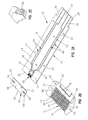
- Fig. 2A is an exploded perspective view of the biosensor of Fig. 1.
- Fig. 2B is an enlarged view of the biosensor of Fig. 2A showing the biosensor including a recess with a plurality of microstructures extending from a first surface of an electrode support substrate.
- Fig. 2 C is an enlarged view of the biosensor of Fig. 1 with portions broken away showing a reagent positioned on an electrode array.
- Fig. 3 is a view taken along lines 3-3 of Fig. 1.
- Fig. 4 is a view taken along lines 4-4 of Fig. 1.
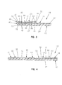
- Fig. 5 is a bottom perspective view of a cover in accordance with one aspect of the invention showing the cover including a channel and plurality of square-shaped posts formed in the channel.
- Fig. 6 is a bottom perspective view of a cover in accordance with another aspect of the invention showing the cover including a channel and plurality of round posts formed in the channel.
- Fig. 7 is a bottom perspective view of a cover in accordance with another aspect of the invention showing the cover including a channel and two spaced-apart bar-shaped posts formed in the channel.
- Fig. 8 is a bottom perspective view of a cover in accordance with another aspect of the invention showing the cover including a channel and plurality of bar-shaped posts formed in the channel.
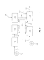
- Fig. 9 is a diagrammatic view of a manufacturing method in accordance with the present invention.
- Fig. 10 is a perspective view of a biosensor in accordance with the present invention.
- Fig. 11 is a bottom perspective view of the cover of the biosensor of Fig. 10.
-
- The present invention relates to a biosensor and method of manufacturing a biosensor that is formed to provide a well-controlled fluid flow and simultaneously reduce the volume of liquid sample required for testing. Biosensors can take the form of any number of diagnostic biosensors including, for example, electrochemical and photometric biosensors. Aspects of the invention are presented in Figs. 1-11, which are not drawn to scale and wherein like components in the several views are numbered alike.
- A
biosensor 10 for testing for biologically significant analytes of an applied biological fluid is shown in Figs. 1-5. The term analyte, as used herein, refers to the molecule or compound to be quantitatively determined. Non-limiting examples of analytes include carbohydrates, proteins, such as hormones and other secreted proteins, enzymes, and cell surface proteins; glycoproteins; peptides; small molecules; polysaccharides; antibodies (including monoclonal or polyclonal Ab); nucleic acids; drugs; toxins; viruses of virus particles; portions of a cell wall; and other compounds processing epitopes. The analyte of interest preferably comprises glucose. -
Biosensor 10 has an electrode-support substrate 12, anelectrical conductor 14 positioned on thesubstrate 12 that is disrupted to defineelectrodes cover substrate 20 positioned onsubstrate 12.Biosensor 10 is in the form of a disposable test strip. It is appreciated however, thatbiosensor 10 can assume any number of forms and shapes in accordance with this disclosure.Biosensor 10 is preferably produced from rolls of material however, it is understood thatbiosensor 10 can be constructed from individual sheets in accordance with this disclosure. Thus, whenbiosensors 10 are produced from rolls, the selection of materials necessitates the use of materials that are sufficiently flexible for roll processing, but which are still rigid enough to give a useful stiffness to finishedbiosensor 10. - Referring to Fig. 1, the electrode-
support substrate 12 includes afirst surface 22 and asecond surface 24. In addition,substrate 12 has opposite first andsecond ends opposite edges second ends Substrate 12 is generally rectangular in shape, it is appreciated however, thatsupport 12 may be formed in a variety of shapes and sizes in accordance with this disclosure.Substrate 12 may be constructed from a wide variety of insulative materials. Non-limiting examples of insulative materials that provide desirable electrical and structural properties include glass, ceramics, vinyl polymers, polyimides, polyesters, and styrenics. Preferably,substrate 12 is a flexible polymer, such as a polyester or polyimide. A non-limiting example of a suitable material is 5 mil (125 µm) thick KALADEX®, a polyethylene naphthalate film commercially available from E.I. DuPont de Nemours, Wilmington, Delaware, which is coated with gold by: ROWO Coatings, Herbolzheim, Germany. -
Electrodes conductor 14 onfirst surface 22 of electrode-support substrate 12.Electrodes conductor 14 bygaps 66. See Fig. 4. It is also appreciated thatelectrodes electrical conductor 14 include aluminum, carbon (such as graphite), cobalt, copper, gallium, gold, indium, iridium, iron, lead, magnesium, mercury (as an amalgam), nickel, niobium, osmium, palladium, platinum, rhenium, rhodium, selenium, silicon (such as highly doped polycrystalline silicon), silver, tantalum, tin, titanium, tungsten, uranium, vanadium, zinc, zirconium, mixtures thereof, and alloys, oxides, or metallic compounds of these elements. Preferably,electrical conductor 14 is selected from the following materials: gold, platinum, palladium, iridium, or alloys of these metals, since such noble metals and their alloys are unreactive in biological systems. Most preferably,electrical conductor 14 is gold. -
Electrodes electrical conductor 14 by laser ablation. Techniques for forming electrodes on a surface using laser ablation are known. See, for example, U.S. Patent Application Serial No. 09/411,940 (published as WO 01/25775), titled "Laser Defined Features for Patterned Laminates and Electrodes", the disclosure of which is expressly incorporated herein by reference. Preferably,electrodes electrical conductor 14 from an area extending around the electrodes to form a gap of exposedsupport substrate 12. Therefore,electrodes substrate 12 by a gap having a width of about 25 µm to about 500 µm, preferably the gap has a width of about 100 µm to about 200 µm. Alternatively, it is appreciated thatelectrodes substrate 12. - It is appreciated that while laser ablation is the preferred method for forming
electrodes - As shown in Fig. 2A,
electrodes electrode array 34. In addition,electrodes contact 36 and a lead 38 extending between thecontact 34 and thearray 36. It is appreciated that theleads 38 extending from thearray 34 can be formed to have many lengths and extend to a variety of locations on the electrode-support substrate 12. It is appreciated that the configuration of the electrode array, the number of electrodes, as well as the spacing between the electrodes may vary in accordance with this disclosure and that a greater than one array may be formed as will be appreciated by one of skill in the art. - Referring now to Figs. 2A and 2B, a
recess 40 is formed through theelectrical conductor 14 and a portion of thefirst surface 22 of thesupport substrate 12 by laser ablation using techniques as described above. Therecess 40 extends fromend 26 of thesubstrate 12 to theelectrode array 34. Therecess 40 is defined further bywalls 44. See Fig. 2B. It is appreciated that the amount of thesupport substrate 12 that is removed can vary in accordance with the present disclosure. It is also appreciated thatsubstrate 12 ofbiosensor 10 can be formed without a recess in accordance with the present disclosure. - As best shown in Fig. 2B, the
recess 40 includes a plurality ofmicrostructures 42 extending from thefirst surface 22 of thesupport substrate 12. Themicrostructures 42 are spaced-apart from one another, on a nearest neighbor basis, by a first distance that is less than the distance necessary to achieve capillary flow of liquid between the microstructures.Microstructures 42 are formed as posts that extend away from the substrate through therecess 40. See Fig. 3. Eachmicrostructure 42 includes afixed end 78 coupled to thesubstrate 12 and an oppositefree end 80.Free end 80 exposed inchannel 40 is metallic-coated. Thesubstrate 12 is also cleaned, removing polymeric debris and other organic material and increasing the surface energy of surfaces of both the surface of thechannel 40 and themicrostructures 42. - It is appreciated that the
microstructures 42 can assume a variety of shapes and sizes in accordance with the present disclosure. Illustratively, therecess 40 includes six rows of sixteenmicrostructures 42. The number and location ofmicrostructures 42 depend upon the size ofbiosensor 10. Therecess 40 may in fact be formed without microstructures in accordance with the present disclosure. In addition, it is also appreciated that themicrostructures 42 may be positioned in a variety of locations in therecess 40. Although not shown, at least some of the microstructures can be joined to the walls 44 (Fig. 1) of therecess 40. - The
cover substrate 20 is coupled to the electrode-support substrate 12 adjacent to thefirst end 26. See Fig. 1. Thecover substrate 20 ofbiosensor 10 includes afirst surface 46 facingsubstrate 12 and an oppositesecond surface 48. See Fig. 3. In addition,cover substrate 20 has opposite first and second ends 50, 52 andedges Openings 58 extend between first andsecond surfaces surface cover substrate 20 is coupled to thesupport substrate 12,openings 58 are offset fromarray 34. See, Fig. 1. It is appreciated, however, that any number ofopenings 58 can be located in a number of locations and take on a variety of shapes and sizes in accordance with this disclosure. - The
cover substrate 20 is formed of a flexible polymer and preferably from a polymer such as polyester. Referring now to Fig. 3, in preferred embodiments, thefirst surface 46 of thecover substrate 20 is coated with ametallic material 88 and preferably with a metal such as gold, platinum, palladium, and iridium. Preferably, thecover substrate 20 is 3 mil (75 µm) Clear PEN film named KALADEX by DuPont and gold coated by: ROWO Coatings, Herbolzheim, Germany. - The
cover substrate 20 is formed to include acapillary channel 60 and secondary capillary recesses 86 spaced-apart fromchannel 60. See Fig. 5. Thecapillary channel 60 is formed to provide a well-controlled fluid flow and simultaneously reduce the volume of liquid required inbiosensor 10. As shown in Fig. 5, thecapillary channel 60 extends between first and second ends 50, 52 and is defined byinterior borders 64. The secondary capillary recesses 86 also extend between first and second ends 50, 52 and are defined by inner andouter borders capillary channel 60 and secondary capillary recesses 86 are formed through at least the material 88 and preferably through a portion of the first surface 46 (Fig. 3) of thecover substrate 20 by laser ablation using techniques as described above. It is appreciated that the amount of thecover substrate 20 that is removed can vary in accordance with the present disclosure. - As shown in Fig. 5, the
capillary channel 60 includes a plurality ofmicrostructures 62. Themicrostructures 62 are spaced-apart from one another, on a nearest neighbor basis, by a first distance that is less than the distance necessary to achieve capillary flow of liquid between the microstructures. Thecapillary channel 60 illustrated in Fig. 5 includes sixteen rows of sixteenmicrostructures 62. The number and location ofmicrostructures 62 depend upon the size of biosensor.Microstructures 62 shown in Fig. 5 are formed as generally square-shaped posts. It is appreciated, however, that microstructures can have a variety of shapes and sizes, non-limiting examples of which are illustrated in Figs. 6-8 and 11, in accordance with this disclosure. -
Microstructures 62 extend away from thecover substrate 20 into thecapillary channel 60. See Fig. 5. Eachmicrostructure 62 includes afixed end 96 coupled to thecover substrate 20 and an oppositefree end 98. Thecover substrate 20 is also cleaned, removing polymeric debris and other organic material present and increasing the surface energy of surfaces of both the surface of thechannel 60 and themicrostructures 42. It is also appreciated that themicrostructures 62 may be positioned in a variety of locations in thechannel 60 as discussed above with reference tomicrostructures 42. - Once the
cover substrate 20 is coupled to thesupport substrate 12, thechannel 60 is aligned withrecess 40.Channel 60 has a height of about 1 µm to about 60µm, preferably 2µm to about 30µm, and most preferably about 5µm to about 15µm. In addition, the width ofchannel 60 betweeninterior borders 64 is about 1 mm to about 4 mm, preferably 1.5 mm to about 3.0 mm, most preferably about 2.0 mm to about 2.5 mm. Thechannel 60 and therecess 40 cooperate to define a capillary path. It is appreciated that when thesubstrate 12 does not include therecess 40, thechannel 60 itself will define the capillary path. Moreover, it is appreciated that while the capillary path is illustratively straight, the capillary path may be curved and/or include turns. - The
cover substrate 20 is coupled to the electrode-support substrate 12 with an adhesive to create sealedportions 82 spaced-apart from thearray 34 and an unsealedportion 84 extending between ends 50, 52 and across at least a portion of thearray 34. See Figs. 1 and 5. Referring now to Fig. 5, each sealedportion 82 has an interior border that lies in general alignment with secondary capillary recesses 86 and an exterior border. The exterior border of each sealedportion 82 lies in general alignment with arespective edge support substrate 12. Although the sealedportions 82 are not distinguishable to the user, it is appreciated that thecover substrate 20 can be at least partially transparent, exposing therecess 40 to the user when a colored fluid such as blood flows it. In addition, it is appreciated that the shape and size of thecover substrate 20 can vary in accordance with this disclosure. - The
cover substrate 20 is coupled to thesupport substrate 12 by a liquid adhesive. A non-limiting example of such an adhesive is EPO-TEK OH100-4 commercially available from Epoxy Technology, Billerica, MA. Preferably, a heated tool is applied on the area where bonding is to take place to promote fast curing. It is appreciated that thecover substrate 20 may be coupled to thesupport substrate 12 using a wide variety of commercially available adhesives as well as heat sealing, or ultrasonic methods of joining thecover substrate 20 andsupport substrate 12 together in accordance with this disclosure. - Referring now to Fig. 2C, a
reagent 68 is positioned on thearray 36. When the biosensor is an electrochemical biosensor, thereagent 68 provides electrochemical probes for specific analytes. It is appreciated, however, thatreagent 68 can also be formed for use in a photometric biosensor. When, however, biosensor is a photometric biosensor, other aspects of the biosensor construction will change to accommodate photometric measurements. Such a construction is well known in the art. The choice of thespecific reagent 68 depends on the specific analyte or analytes to be measured, and are well known to those of ordinary skill in the art. An example of a reagent that may be used inbiosensor 10 of the present invention is a reagent for measuring glucose from a whole blood sample. A non-limiting example of a reagent for measurement of glucose in a human blood sample contains 62.2 mg polyethylene oxide (mean molecular weight of 100-900 kilo Daltons), 3.3 mg NATROSOL 244M, 41.5 mg AVICEL RC-591 F, 89.4 mg monobasic potassium phosphate, 157.9 mg dibasic potassium phosphate, 437.3 mg potassium ferricyanide, 46.0 mg sodium succinate, 148.0 mg trehalose, 2.6 mg TRITON X-100 surfactant, and 2,000 to 9,000 units of enzyme activity per gram of reagent. The enzyme is prepared as an enzyme solution from 12.5 mg coenzyme PQQ and 1.21 million units of the apoenzyme of quinoprotein glucose dehydrogenase. This reagent is further described in U.S. Patent No. 5,997,817, the disclosure of which is expressly incorporated herein by reference. - Non-limiting examples of enzymes and mediators that may be used in measuring particular analytes in
biosensor 10 are listed below in Table 1.Analyte Enzymes Mediator Additional Mediator (Oxidized Form) Glucose Glucose Dehydrogenase Ferricyanide and Diaphorase Glucose Glucose-Dehydrogenase Ferricyanide (Quinoprotein) Cholesterol Cholesterol Esterase and Ferricyanide 2,6-Dimethyl-1,4- Cholesterol Oxidase Benzoquinone 2,5-Dichloro-1,4- Benzoquinone or Phenazine Ethosulfate HDL Cholesterol Esterase Ferricyanide 2,6-Dimethyl-1,4- Cholesterol and Cholesterol Oxidase Benzoquinone 2,5-Dichloro-1,4- Benzoquinone or Phenazine Ethosulfate Triglycerides Lipoprotein Lipase, Ferricyanide or Phenazine Methosulfate Glycerol Kinase, and Phenazine Glycerol-3-Phosphate Ethosulfate Oxidase Lactate Lactate Oxidase Ferricyanide 2,6-Dichloro-1,4- Benzoquinone Lactate Lactate Dehydrogenase Ferricyanide and Diaphorase Phenazine Ethosulfate, or Phenazine Methosulfate Lactate Diaphorase Ferricyanide Phenazine Ethosulfate, or Dehydrogenase Phenazine Methosulfate Pyruvate Pyruvate Oxidase Ferricyanide Alcohol Alcohol Oxidase Phenylenediamine Bilirubin Bilirubin Oxidase 1-Methoxy- Phenazine Methosulfate Uric Acid Uricase Ferricyanide - In some of the examples shown in Table 1, at least one additional enzyme is used as a reaction catalyst. Also, some of the examples shown in Table 1 may utilize an additional mediator, which facilitates electron transfer to the oxidized form of the mediator. The additional mediator may be provided to the reagent in lesser amount than the oxidized form of the mediator. While the above assays are described, it is contemplated that current, charge, impedance, conductance, potential, or other electrochemically indicated property of the sample might be accurately correlated to the concentration of the analyte in the sample with
biosensor 10 in accordance with this disclosure. - A plurality of
biosensors 10 are typically packaged in a vial, usually with a stopper formed to seal the vial. It is appreciated, however, thatbiosensors 10 may be packaged individually, or biosensors can be folded upon one another, rolled in a coil, stacked in a cassette magazine, or packed in blister packaging. -
Biosensor 10 is used in conjunction with the following: - 1. a power source in electrical connection with
contacts 36 and capable of supplying an electrical potential difference betweenelectrodes - 2. a meter in electrical connection with
contacts 36 and capable of measuring the diffusion limited current produced by oxidation of the reduced form of the mediator with the above-stated electrical potential difference is applied. -
- The meter will normally be adapted to apply an algorithm to the current measurement, whereby an analyte concentration is provided and visually displayed. Improvements in such power source, meter, and biosensor system are the subject of commonly assigned U.S. Pat. No. 4,963,814, issued Oct. 16, 1990; U.S. Pat. No. 4,999,632, issued Mar. 12, 1991; U.S. Pat. No. 4,999,582, issued Mar. 12, 1991; U.S. Pat. No. 5,243,516, issued Sep. 7, 1993; U.S. Pat. No. 5,352,351, issued Oct. 4, 1994; U.S. Pat. No. 5,366,609, issued Nov. 22, 1994; White et al., U.S. Pat. No. 5,405,511, issued Apr. 11, 1995; and White et al., U.S. Pat. No. 5,438,271, issued Aug. 1, 1995, the disclosures of each of which are expressly hereby incorporated by reference.
- Many fluid samples may be analyzed. For example, human body fluids such as whole blood, plasma, sera, lymph, bile, urine, semen, cerebrospinal fluid, spinal fluid, lacrimal fluid and stool specimens as well as other biological fluids readily apparent to one skilled in the art may be measured. Fluid preparations of tissues can also be assayed, along with foods, fermentation products and environmental substances, which potentially contain environmental contaminants. Preferably, whole blood is assayed with this invention.
- As shown in Fig. 9,
biosensor 10 is manufactured by feeding a roll of metallized electrode support material through guide rolls 70 into afirst ablation station 72 as shown byarrow 74. A laser system capable of ablatingsupport 12 is known to those of ordinary skill in the art. Non-limiting examples of which include excimer lasers, with the pattern of ablation controlled by mirrors, lenses, and masks. A non-limiting example of such a custom fit system is the LPX-300 or LPX-200 both commercially available from LPKF Laser Electronic GmbH, of Garbsen, Germany, equipped with a 248 nm wavelength excimer laser. It is appreciated that higher wavelength UV lasers can, however, be used in accordance with this disclosure. - In the first
laser ablation station 72, the metallic layer of the metallized film is ablated in a pre-determined pattern, to form a ribbon of isolated electrode sets on the electrode support material. To ablateelectrodes gaps 66 in 50 nmthick gold conductor - Next, the ribbon is fed, as shown by
arrow 76 into a secondlaser ablation station 100.Station 100 is similar tostation 72. In thesecond station 100, thefirst surface 22 of thesupport substrate 12 is ablated in a pre-determined pattern, to form therecess 40 extending about themicrostructures 42. To ablate therecess 40 in 50 nmthick gold conductor surface 22, multi-pulses of the laser light are applied. In preferred embodiments, three to five pulses of laser light (90 mJ/cm2 in each pulse) are applied. It is appreciated the depth of ablation into thesurface 22 can vary. Moreover, it is appreciated that the number of pulses applied will very depending upon the polymer and the depth of ablation. For example, as the hardness of the polymer increases the number of pulses will increase (a non-limiting example of which is 25 pulses) and as the hardness of polymer decreases, the number of pulses necessary to ablate thesurface 22 decreases. If any seed layer or other metallic layer such as Chromium or Titanium or any other metal is used for any purpose, and then gold is put down on top of the seed layer or other metallic layer, the total thickness of all composite metals is still preferred to be 50 nm. It is appreciated, however, if the total thickness is higher, a higher energy laser will be needed. - Upon leaving the second
laser ablation station 100, the ablated material that is in either roll form or that has been cut into cards is fed as shown byarrow 101 to a microwave plasma machine 111, a custom-fit equipment, which is commercially available from TePla AG, Kircheim, Germany. The ablated material is cleaned by the microwave plasma machine to remove polymeric debris and other organic material and to increase the hydrophilicity of thechannel 40 andmicrostructures 42. Non-limiting parameters of a plasma machine are as follows: pressure = 0.44 mbar; gas = Oxygen; Microwave power= 300 watt; time = about 30 to about 60 seconds. Cleaning with the microwave plasma machine results in increased surface energy as well as the removal or loose particles, making the surfaces very hydrophilic, which helps increase the blood flow rate and fluid spreading. For example, the surface energy ofrecess 42 as well as thesurface 14 before treatment with the plasma machine is approximately 41mN/m. The surface energy after the treatment is approximately 72 mN/m. - Upon leaving the microwave plasma machine 111, the metallized film is fed as shown by
arrow 103 into areagent dispensing station 104. Reagents that have been compounded are fed, as shown byarrow 106, into the dispensingstation 104 where it is applied in a liquid form in multiple shots to thearray 34. It is appreciated, however, that the reagent can be applied by multi or single dose by a custom fit precision dispensing station available from Fluilogic Systems Oy, Espoo, Finland. Reagent application techniques are well known to one of ordinary skill in the art as described in U.S. Patent No. 5,762,770, the disclosure of which is expressly incorporated herein by reference. It is appreciated that reagents may be applied to thearray 34 in a liquid or other form and dried or semi-dried onto thearray 34 in accordance with this disclosure. - In a separate process, a roll of metallized film through guide rolls 108 into a
third ablation station 110 as shown byarrow 112. Thestation 110 is similar tostation 72. It is appreciated that although three laser ablation stations are illustrated and described, that greater or fewer than three stations may be used in accordance with the disclosure. In thethird station 110, the metallized film andfirst surface 46 of the material is ablated in a pre-determined pattern, to form thecapillary channel 60 extending aboutmicrostructures 62 and secondary capillary recesses 86. To ablatechannel 60 and recesses 86 in 50 nmthick gold conductor surface 46, multi-pulses of the laser light are applied. In preferred embodiments, three to five pulses of laser light (90 mJ/cm2 in each pulse) are applied. It is appreciated the depth of ablation into thesurface 46 can vary. Moreover, it is appreciated that the number of pulses applied will very depending upon the polymer and the depth of ablation. For example, as the hardness of the polymer increases the number of pulses will increase (a non-limiting example of which is 25 pulses) and as the hardness of polymer decreases, the number of pulses necessary to ablate thesurface 46 decreases. If any seed layer or other metallic layer such as Chromium or Titanium or any other metal is used for any purpose, and then gold is put down on top of the seed layer or other metallic layer, the total thickness of all composite metals is still preferred to be 50 nm. It is appreciated, however, if the total thickness is higher, a higher energy laser will be needed. - Upon leaving the third
laser ablation station 110, the ablated material that is in either roll form or that has been cut into cards is fed as shown byarrow 105 to the microwave plasma machine 111. It is appreciated, however, that a second plasma machine could also be used in accordance with this invention. Cleaning with the plasma machine 111 results in the removal of polymeric debris and other organic materials and increased surface energy, making the surfaces very hydrophilic, which helps increase the blood flow rate and fluid spreading. For example, the surface energy of thecapillary channel 60 as well as thesurface 46 before treatment with the plasma machine is approximately 41mN/m. The surface energy after the treatment is approximately 72 mN/m. - Upon leaving the microwave plasma machine 111, the film is then fed as shown by arrow 114 into a sensor lamination and cut/
pack station 116. At the same time, the reagent-coated film is fed, as shown by arrow 118 into thestation 116. The cover support material is punched to formopenings 58. Thefirst surface 46 of the cover support material is then applied to the electrode-support substrate material over theelectrode arrays 34. Next, a liquid adhesive is dispensed, as shown byarrow 120 throughopenings 58 of the cover substrate material in thestation 116. A heated tool is applied on the area where bonding is to take place to promote fast curing of the adhesive between isolated gold surfaces 46 and 14. - The resulting assembled material is cut to form
individual biosensors 10, which are sorted and packed into vials, each closed with a stopper, to give packaged biosensor strips as shown byarrow 122. - In use, for example, a user of
biosensor 10 places a finger having a blood collection incision against ends 26, 50 adjacent to openings ofrecess 40 andchannel 60. See, Fig. 3. Capillary forces pull a liquid sample flowing from the incision through thecapillary channel 60 across thereagent 68 and thearray 36. The liquid sample dissolves thereagent 68 and engages thearray 36 where the electrochemical reaction takes place. - The user then inserts the
biosensor 10 into a meter (not shown) where an electrical connection is made between theelectrode contacts 36 and a meter contact (not shown) in the meter. It is appreciated that thebiosensor 10 also may be inserted into the meter at any number of times including prior to the sample flowing into the openingchannel 60. Once the reaction is complete, a power source (e.g., a battery) applies a potential difference between theelectrodes - The measured current may be accurately correlated to the concentration of the analyte in sample when the following requirements are satisfied:
- 1. The rate of oxidation of the reduced form of the mediator is governed by the rate of diffusion of the reduced form of the mediator to the surface of the working electrode.
- 2. The current produced is limited by the oxidation of reduced form of the mediator at the surface of the working electrode.
-
- In another aspect of the invention, a
cover substrate 220 is provided in accordance with the present disclosure.Cover substrate 220 is shown in Fig. 6 and is suitable for use with the electrode-support substrate 12. Thecover substrate 220 is coupled to the electrode-support substrate 12 adjacent to thefirst end 26. Thecover substrate 220 is formed of a flexible polymer coated with a metallic material similar to coversubstrate 20. - The
cover substrate 220 is formed to include acapillary channel 260 and secondary capillary recesses 86 spaced-apart fromchannel 260. Likechannel 60 incover 20, thecapillary channel 260 is also formed to provide a well controlled fluid flow and simultaneously reduce the volume of liquid required when it cooperates withsupport substrate 12 in a biosensor. Thecapillary channel 260 and secondary capillary recesses 86 are formed through at least the material 88 and preferably through a portion of thefirst surface 46 of thecover substrate 220 by laser ablation using techniques as described above. It is appreciated that the amount of thecover substrate 220 that is removed can vary in accordance with the present disclosure. - As shown in Fig. 6, the
capillary channel 260 includes a plurality ofmicrostructures 262. Themicrostructures 262 are spaced-apart from one another, on a nearest neighbor basis, by a first distance that is less than the distance necessary to achieve capillary flow of liquid between the microstructures. It is appreciated that thecapillary channel 260 can include greater or fewer than the illustrated microstructures in accordance with this disclosure.Microstructures 262 are formed as generally round-shaped posts. It is appreciated, however, that microstructures can have a variety of shapes and sizes in accordance with this disclosure. In addition, thecover substrate 220 is also cleaned, as described above with reference to cover 20, increasing the surface energy of surfaces of both the surface of thechannel 40 and themicrostructures 42. - In another aspect of the invention, a
cover substrate 320 is provided in accordance with the present disclosure.Cover substrate 320 is shown in Fig. 7 and is suitable for use with the electrode-support substrate 12. Thecover substrate 320 is coupled to the electrode-support substrate 12 adjacent to thefirst end 26. Thecover substrate 320 is formed of a flexible polymer coated with a metallic material similar to coversubstrate 20. - The
cover substrate 320 is formed to include acapillary channel 360 and secondary capillary recesses 86 spaced-apart fromchannel 360. Likechannel 60 incover 20, thecapillary channel 360 is also formed to provide a well controlled fluid flow and simultaneously reduce the volume of liquid required when it cooperates withsupport substrate 12 in a biosensor. Thecapillary channel 360 and secondary capillary recesses 86 are formed through at least the material 88 and preferably through a portion of thefirst surface 46 of thecover substrate 320 by laser ablation using techniques as described above. It is appreciated that the amount of thecover substrate 320 that is removed can vary in accordance with the present disclosure. Further, thecover substrate 320 is also cleaned, as described above with reference to cover 20, increasing the surface energy of the surface of thechannel 360. - In another aspect of the invention, a
cover substrate 420 is provided in accordance with the present disclosure.Cover substrate 420 is shown in Fig. 8 and is suitable for use with the electrode-support substrate 12. Thecover substrate 420 is coupled to the electrode-support substrate 12 adjacent to thefirst end 26. Thecover substrate 420 is formed of a flexible polymer coated with a metallic material similar to coversubstrate 20. - The
cover substrate 420 is formed to include acapillary channel 460 and secondary capillary recesses 86 spaced-apart fromchannel 460. Likechannel 60 incover 20, thecapillary channel 460 is also formed to provide a well controlled fluid flow and simultaneously reduce the volume of liquid required when it cooperates withsupport substrate 12 in a biosensor. Thecapillary channel 460 and secondary capillary recesses 86 are formed through at least the material 88 and preferably through a portion of thefirst surface 46 of thecover substrate 420 by laser ablation using techniques as described above. It is appreciated that the amount of thecover substrate 420 that is removed can vary in accordance with the present disclosure. - As shown in Fig. 8, the
capillary channel 460 includes a plurality ofmicrostructures 462. Themicrostructures 462 are spaced-apart from one another, on a nearest neighbor basis, by a first distance that is less than the distance necessary to achieve capillary flow of liquid between the microstructures. Illustratively, thecapillary channel 460 includes five rows ofmicrostructures 462. It is appreciated that thecapillary channel 460 can include greater or fewer than the illustrated microstructures in accordance with this disclosure.Microstructures 462 are formed as generally bar-shaped posts. It is appreciated, however, that microstructures can have a variety of shapes and sizes in accordance with this disclosure. Further, thecover substrate 420 is also cleaned, as described above with reference to cover 20, increasing the surface energy of surfaces of both the surface of thechannel 460 and themicrostructures 462. - As shown in Fig. 10,
biosensor 510 is formed to include an electrode-support substrate 512. Substrate 512 is formed in a similar manner tosubstrate 12, except that theelectrode array 34 is spaced-apart fromfirst end 26 and arecess 540 includingmicrostructures 42 extends betweenend 26 andarray 34. The recess is formed through theelectrical conductor 14 and a portion of thefirst surface 22 of the support substrate 512 by laser ablation using techniques as described above. It is appreciated that the amount of the support substrate 512 that is removed can vary in accordance with the present disclosure. It is also appreciated that substrate 512 ofbiosensor 510 can be formed without a recess in accordance with the present disclosure. It is also appreciated that themicrostructures 42 can assume a variety of shapes and sizes in accordance with the present disclosure. - The
cover substrate 520 is coupled to the electrode-support substrate 12 adjacent to thefirst end 26. See Fig. 10. Thecover substrate 520 is formed of materials similar to thecover substrate 20 as described above. Referring now to Fig. 11, thecover substrate 520 is formed to include acapillary channel 560 and secondary capillary recesses 86 spaced-apart fromchannel 560. Thecapillary channel 560 is formed to provide a well-controlled fluid flow and simultaneously reduce the volume of liquid required inbiosensor 510. Thecapillary channel 560 extends between first and second ends 50, 52 and is defined byinterior borders 64. Thecapillary channel 560 and secondary capillary recesses 86 are formed through at least the material 88 and preferably through a portion of the first surface of thecover substrate 20 by laser ablation using techniques as described above. It is appreciated that the amount of thecover substrate 520 that is removed can vary in accordance with the present invention. - As shown in Fig. 11, the
capillary channel 560 includesmicrostructures 62 that are formed as described above with reference tobiosensor 10. It is appreciated that themicrostructures 62 can assume a variety of shapes and sizes the number and location ofmicrostructures 62 depend upon the size of biosensor in accordance with the present disclosure. - In addition, the
cover substrate 520 is formed to include aninlet 522 that extends between first andsecond surfaces capillary channel 560. When thecover substrate 520 is coupled to the support substrate 512, theinlet 522 is offset from thearray 34. See, Fig. 10. It is appreciated, however, thatinlet 522 can be located in a number of locations in thechannel 560 in accordance with this disclosure, a non-limiting example of which includes theinlet 522 intersectingend 50 ofcover substrate 520. -
Biosensor 510 is manufactured in a manner similar tobiosensor 10 as described above. Recess 540 of thebiosensor 510 is formed in the secondlaser ablation station 100 by ablating thefirst surface 22 in a pre-defined pattern to form therecess 540 extending betweenend 26 and thearray 36. The hydrophilicity of thechannel 540 andmicrostructures 42 are increased due to cleaning by a plasma machine 111 as described above with reference tobiosensor 10. -
Capillary channel 560 is formed in the cover substrate material in thethird ablation station 110 as described above with reference tobiosensor 10. The ablated material is cleaned by the plasma machine 111 to remove polymeric debris and other organic materials and increasing the hydrophilicity of thechannel 560 andmicrostructures 62. The film is then fed into the sensor lamination and cut/pack station 116 whereopenings 58 andinlet 522 are punched. - As described above with reference to
biosensor 10, a liquid adhesive is dispensed, throughopenings 58 of the cover substrate material and a heated tool is applied on the area where bonding is to take place to promote fast curing of the adhesive. The resulting assembled material is cut to formindividual biosensors 510, which are sorted and packed into vials, each closed with a stopper, to give packaged biosensor strips. Thebiosensor 510 is used in a manner similar tobiosensor 10 as described above. - Although the invention has been described in detail with reference to a preferred embodiment, variations and modifications exist within the scope and spirit of the invention, as described and defined in the following claims.
Claims (27)
- A biosensor comprising:a substrate, anda cover extending across at least a portion of the substrate, the cover including a first surface facing the substrate and a second surface, at least a portion of the first surface being removed to define a capillary channel, the capillary channel having a surface energy ranging from about 60 mN/m to about 72 mN/m.
- The biosensor of claim 1 wherein the first surface is formed to include at least one microstructure extending into the channel.
- The biosensor of claim 2 wherein at least one of the microstructures has a round post-like shape.
- The biosensor of claim 2 wherein at least one of the microstructures has a generally square post-like shape.
- The biosensor of claim 2 wherein the capillary channel includes opposite ends and at least two of the microstructures include a front side facing one end and a back side facing the opposite end and opposite inner and outer edges that extend between the front and back sides.
- The biosensor of claim 5 wherein the front side and the back side each have a greater dimension than the inner and outer edges.
- The biosensor of claim 1 wherein the first surface includes spaced-apart secondary capillary recesses.
- The biosensor of claim 1 wherein at least a portion of the first surface includes a metallic coating.
- The biosensor of claim 6 wherein the metallic coating is gold.
- A biosensor comprising:a capillary path defined between a substrate and a cover, andat least one microstructure positioned in the capillary path, the at least onemicrostructure including a fixed end coupled to either the substrate or the cover and an opposite free end, wherein the free end is metallic.
- The biosensor of claim 10 wherein the capillary path has a surface energy ranging from about 60 mN/m to about 72 mN/m.
- The biosensor of claim 10 wherein the free end is coated with a metal selected from the group consisting of gold, platinum, palladium, and iridium.
- The biosensor of claim 12 wherein the metal is gold.
- The biosensor of claim 10 wherein at least one of the microstructures has a round post-like shape.
- The biosensor of claim 10 wherein at least one of the microstructures has a generally square post-like shape.
- A biosensor comprising:a substrate,electrodes positioned on the substrate,a cover extending across at least a portion of the substrate to define a capillary path, andat least one microstructure positioned in the capillary path, the at least one microstructure including a fixed end coupled to the cover and an opposite free end, wherein the free end is metallic.
- The biosensor of claim 16 wherein the free end formed of a metal selected from the group consisting of gold, platinum, palladium, and iridium.
- The biosensor of claim 16 wherein the metal is gold.
- The biosensor of claim 16 wherein the microstructures have a surface energy ranging from about 60 mN/m to about 72 mN/m.
- A method of forming biosensor, the method comprising the steps of:providing a substrate, a reagent for the measurement of at least one analyte, and a cover, the cover including a first surface,exposing the cover to at least one pulse of light of sufficient to ablate the first surface in a pre-determined pattern creating a channel,cleaning the first surface of the cover so that the surface energy of the channelranges from about 60 mN/m to about 72 mN/m, andplacing the first surface of the cover upon the substrate to define a capillary path and the reagent is positioned in the capillary path.
- The method of claim 20 wherein the first surface is cleaned by a microwave plasma machine.
- The method of claim 20 wherein the first surface is ablated to create microstructures in the channel.
- The method of claim 20 further comprising the step of forming electrodes on the substrate.
- The method of claim 23 wherein the forming step includes exposing the substrate to at least one pulse of light sufficient to ablate a portion of the substrate about the electrodes.
- The method of claim 23 further comprising the step of exposing the substrate to at least an additional pulse of light sufficient to ablate a portion of the substrate creating at lest one microstructure extending from the substrate.
- The method of claim 23 further comprising the step of cleaning the substrate to increase the surface energy of the substrate.
- The method of claim 20 further comprising the steps of positioning a mask having a pre-defined pattern over the first surface and exposing the mask and the cover to at least one pulse of light sufficient to ablate the exposed surface of the cover creating at least one microstructure extending from the cover.
Applications Claiming Priority (2)
| Application Number | Priority Date | Filing Date | Title |
|---|---|---|---|
| US09/974,434 US6755949B1 (en) | 2001-10-09 | 2001-10-09 | Biosensor |
| US974434 | 2001-10-09 |
Publications (3)
| Publication Number | Publication Date |
|---|---|
| EP1302545A2 true EP1302545A2 (en) | 2003-04-16 |
| EP1302545A3 EP1302545A3 (en) | 2003-11-05 |
| EP1302545B1 EP1302545B1 (en) | 2010-05-19 |
Family
ID=25522030
Family Applications (1)
| Application Number | Title | Priority Date | Filing Date |
|---|---|---|---|
| EP02022418A Expired - Lifetime EP1302545B1 (en) | 2001-10-09 | 2002-10-04 | Enzyme Biosensor |
Country Status (6)
| Country | Link |
|---|---|
| US (1) | US6755949B1 (en) |
| EP (1) | EP1302545B1 (en) |
| JP (1) | JP3694285B2 (en) |
| AT (1) | ATE468405T1 (en) |
| CA (1) | CA2407353C (en) |
| DE (1) | DE60236397D1 (en) |
Cited By (4)
| Publication number | Priority date | Publication date | Assignee | Title |
|---|---|---|---|---|
| WO2004100229A2 (en) * | 2003-05-09 | 2004-11-18 | Iongate Biosciences Gmbh | Biocompatible sensor electrode assembly and method for the production thereof |
| WO2007121121A2 (en) * | 2006-04-11 | 2007-10-25 | Home Diagnostics Inc. | Laminated biosensor and its manufacturing method |
| WO2007148285A2 (en) * | 2006-06-19 | 2007-12-27 | Nova Biomedical Corporation | Capillary flow control in a flow channel |
| DE102006020131B4 (en) * | 2006-05-02 | 2012-04-26 | Jinping Liu | Nano- and microstructured biosensor and process for its preparation |
Families Citing this family (36)
| Publication number | Priority date | Publication date | Assignee | Title |
|---|---|---|---|---|
| WO2004097393A1 (en) * | 2003-04-28 | 2004-11-11 | Matsushita Electric Industrial Co., Ltd. | Filter and biosensor having the same |
| EP1667581A1 (en) * | 2003-09-01 | 2006-06-14 | Inverness Medical Switzerland GmbH | Sampling device with capillary action |
| US7588724B2 (en) | 2004-03-05 | 2009-09-15 | Bayer Healthcare Llc | Mechanical device for mixing a fluid sample with a treatment solution |
| AU2005241523A1 (en) * | 2004-05-04 | 2005-11-17 | Bayer Healthcare Llc | Mechanical cartridge with test strip fluid control features for use in a fluid analyte meter |
| US20070191716A1 (en) * | 2004-09-29 | 2007-08-16 | Daniel Goldberger | Blood monitoring system |
| US20060229531A1 (en) * | 2005-02-01 | 2006-10-12 | Daniel Goldberger | Blood monitoring system |
| CN101137908B (en) * | 2005-03-07 | 2012-07-04 | 可乐丽股份有限公司 | Microchannel array and method for producing the same, and blood measuring method employing it |
| US7922883B2 (en) | 2005-06-08 | 2011-04-12 | Abbott Laboratories | Biosensors and methods of using the same |
| US20070123801A1 (en) * | 2005-11-28 | 2007-05-31 | Daniel Goldberger | Wearable, programmable automated blood testing system |
| US20080200838A1 (en) * | 2005-11-28 | 2008-08-21 | Daniel Goldberger | Wearable, programmable automated blood testing system |
| US7811430B2 (en) * | 2006-02-28 | 2010-10-12 | Abbott Diabetes Care Inc. | Biosensors and methods of making |
| WO2007120149A1 (en) * | 2006-04-18 | 2007-10-25 | Home Diagnostics, Inc. | Biosensors comprising heat sealable spacer materials |
| US8092385B2 (en) * | 2006-05-23 | 2012-01-10 | Intellidx, Inc. | Fluid access interface |
| JP4845594B2 (en) * | 2006-05-29 | 2011-12-28 | 富士通株式会社 | Electrochemical cell and potential application method |
| KR100726339B1 (en) | 2006-06-15 | 2007-06-11 | 한국과학기술원 | A microfluidic chip for particle focusing and separation and its separation method |
| US7771655B2 (en) * | 2006-07-12 | 2010-08-10 | Bayer Healthcare Llc | Mechanical device for mixing a fluid sample with a treatment solution |
| EP1964927A1 (en) | 2007-02-27 | 2008-09-03 | F. Hoffmann-La Roche AG | Quinones as mediators for photometric tests |
| EP2208048A1 (en) * | 2007-11-05 | 2010-07-21 | Koninklijke Philips Electronics N.V. | Biosensor cartridge |
| JP5405916B2 (en) * | 2008-06-24 | 2014-02-05 | パナソニック株式会社 | Biosensor, method for manufacturing the same, and detection system including the same |
| EP2166352A1 (en) * | 2008-09-17 | 2010-03-24 | F.Hoffmann-La Roche Ag | Device and method for determining an analyte in a fluid sample |
| EP2345893B1 (en) | 2008-11-04 | 2016-05-04 | Panasonic Healthcare Holdings Co., Ltd. | Measurement device, measurement method, and program |
| KR101048858B1 (en) * | 2009-02-10 | 2011-07-13 | 주식회사 나노엔텍 | Open groove channel chip |
| US8753290B2 (en) * | 2009-03-27 | 2014-06-17 | Intellectual Inspiration, Llc | Fluid transfer system and method |
| KR101104400B1 (en) * | 2009-06-02 | 2012-01-16 | 주식회사 세라젬메디시스 | Biosensor for measuring biomaterial |
| JP5843754B2 (en) * | 2010-03-09 | 2016-01-13 | アークレイ株式会社 | Electrochemical sensor |
| WO2013045487A1 (en) | 2011-09-28 | 2013-04-04 | F. Hoffmann-La Roche Ag | Azo mediators |
| JP6412027B2 (en) | 2013-03-15 | 2018-10-24 | エフ.ホフマン−ラ ロシュ アーゲーF. Hoffmann−La Roche Aktiengesellschaft | Method for fail-safe electrochemical measurement of analyte and device, apparatus and system incorporating the same |
| CN105247356B (en) | 2013-03-15 | 2017-11-07 | 豪夫迈·罗氏有限公司 | Use the method and the unit and system of merging methods described of the information of the recovery pulse in being measured from electrochemical analyte |
| CA2900572C (en) | 2013-03-15 | 2018-02-13 | F. Hoffmann-La Roche Ag | Methods of detecting high antioxidant levels during electrochemical measurements and failsafing an analyte concentration therefrom as well as devices, apparatuses and systems incorporting the same |
| KR101727447B1 (en) | 2013-03-15 | 2017-04-14 | 에프. 호프만-라 로슈 아게 | Methods of scaling data used to construct biosensor algorithms as well as devices, apparatuses and systems incorporating the same |
| US10265025B2 (en) | 2013-06-25 | 2019-04-23 | Biosense Webster (Israel) Ltd. | Electrocardiogram noise reduction |
| CN105092662B (en) * | 2014-05-20 | 2019-01-22 | 光宏精密股份有限公司 | Electrochemical sensing test piece and its manufacturing method |
| CN105277597B (en) * | 2014-07-17 | 2017-09-15 | 光宏精密股份有限公司 | Electrochemical sensing test piece electric-conductor method to set up |
| US9933386B2 (en) * | 2015-06-29 | 2018-04-03 | Kuang Hong Precision Co., Ltd. | Setting method for conductive object of electrochemical test strip |
| JP2019529935A (en) | 2016-10-05 | 2019-10-17 | エフ ホフマン−ラ ロッシュ アクチェン ゲゼルシャフト | Detection reagents and electrode arrangements for multi-sample diagnostic test elements and methods of using them |
| DE102018133553A1 (en) * | 2018-12-21 | 2020-06-25 | Fraunhofer-Gesellschaft zur Förderung der angewandten Forschung eingetragener Verein | Object with a metal substrate and a channel in the metal substrate and method for its production |
Citations (5)
| Publication number | Priority date | Publication date | Assignee | Title |
|---|---|---|---|---|
| US5413690A (en) | 1993-07-23 | 1995-05-09 | Boehringer Mannheim Corporation | Potentiometric biosensor and the method of its use |
| US5762770A (en) | 1994-02-21 | 1998-06-09 | Boehringer Mannheim Corporation | Electrochemical biosensor test strip |
| US5798031A (en) | 1997-05-12 | 1998-08-25 | Bayer Corporation | Electrochemical biosensor |
| US5997817A (en) | 1997-12-05 | 1999-12-07 | Roche Diagnostics Corporation | Electrochemical biosensor test strip |
| EP1120164A2 (en) | 2000-01-28 | 2001-08-01 | Roche Diagnostics GmbH | Fluid flow control in curved capillary channels |
Family Cites Families (42)
| Publication number | Priority date | Publication date | Assignee | Title |
|---|---|---|---|---|
| US4233029A (en) | 1978-10-25 | 1980-11-11 | Eastman Kodak Company | Liquid transport device and method |
| US4271119A (en) | 1979-07-23 | 1981-06-02 | Eastman Kodak Company | Capillary transport device having connected transport zones |
| US4302313A (en) | 1979-07-23 | 1981-11-24 | Eastman Kodak Company | Electrode-containing device with capillary transport between electrodes |
| US4323536A (en) | 1980-02-06 | 1982-04-06 | Eastman Kodak Company | Multi-analyte test device |
| US4618476A (en) | 1984-02-10 | 1986-10-21 | Eastman Kodak Company | Capillary transport device having speed and meniscus control means |
| US5164598A (en) | 1985-08-05 | 1992-11-17 | Biotrack | Capillary flow device |
| US4948961A (en) | 1985-08-05 | 1990-08-14 | Biotrack, Inc. | Capillary flow device |
| GB8709882D0 (en) | 1987-04-27 | 1987-06-03 | Genetics Int Inc | Membrane configurations |
| US5051237A (en) | 1988-06-23 | 1991-09-24 | P B Diagnostic Systems, Inc. | Liquid transport system |
| US5620863A (en) | 1989-08-28 | 1997-04-15 | Lifescan, Inc. | Blood glucose strip having reduced side reactions |
| AU640162B2 (en) | 1989-08-28 | 1993-08-19 | Lifescan, Inc. | Blood separation and analyte detection techniques |
| US5243516A (en) | 1989-12-15 | 1993-09-07 | Boehringer Mannheim Corporation | Biosensing instrument and method |
| US4999632A (en) | 1989-12-15 | 1991-03-12 | Boehringer Mannheim Corporation | Analog to digital conversion with noise reduction |
| US4963814A (en) | 1989-12-15 | 1990-10-16 | Boehringer Mannheim Corporation | Regulated bifurcated power supply |
| US4999582A (en) | 1989-12-15 | 1991-03-12 | Boehringer Mannheim Corp. | Biosensor electrode excitation circuit |
| US5119116A (en) | 1990-07-31 | 1992-06-02 | Xerox Corporation | Thermal ink jet channel with non-wetting walls and a step structure |
| US6156270A (en) | 1992-05-21 | 2000-12-05 | Biosite Diagnostics, Inc. | Diagnostic devices and apparatus for the controlled movement of reagents without membranes |
| US6019944A (en) | 1992-05-21 | 2000-02-01 | Biosite Diagnostics, Inc. | Diagnostic devices and apparatus for the controlled movement of reagents without membranes |
| US5520244A (en) | 1992-12-16 | 1996-05-28 | Sdl, Inc. | Micropost waste heat removal system |
| GB9309797D0 (en) | 1993-05-12 | 1993-06-23 | Medisense Inc | Electrochemical sensors |
| US5405511A (en) | 1993-06-08 | 1995-04-11 | Boehringer Mannheim Corporation | Biosensing meter with ambient temperature estimation method and system |
| US5366609A (en) | 1993-06-08 | 1994-11-22 | Boehringer Mannheim Corporation | Biosensing meter with pluggable memory key |
| US5427663A (en) | 1993-06-08 | 1995-06-27 | British Technology Group Usa Inc. | Microlithographic array for macromolecule and cell fractionation |
| CA2153883C (en) | 1993-06-08 | 1999-02-09 | Bradley E. White | Biosensing meter which detects proper electrode engagement and distinguishes sample and check strips |
| US5352351A (en) | 1993-06-08 | 1994-10-04 | Boehringer Mannheim Corporation | Biosensing meter with fail/safe procedures to prevent erroneous indications |
| US5637458A (en) | 1994-07-20 | 1997-06-10 | Sios, Inc. | Apparatus and method for the detection and assay of organic molecules |
| US5707799A (en) * | 1994-09-30 | 1998-01-13 | Abbott Laboratories | Devices and methods utilizing arrays of structures for analyte capture |
| US5753452A (en) | 1996-04-04 | 1998-05-19 | Lifescan, Inc. | Reagent test strip for blood glucose determination |
| AU3386197A (en) | 1996-06-11 | 1998-01-07 | Dilux, Inc. | Multichannel dilution reservoir |
| EP0909385B1 (en) | 1996-06-28 | 2008-09-10 | Caliper Life Sciences, Inc. | Method of transporting fluid samples within a microfluidic channel |
| US6083761A (en) | 1996-12-02 | 2000-07-04 | Glaxo Wellcome Inc. | Method and apparatus for transferring and combining reagents |
| US6156273A (en) | 1997-05-27 | 2000-12-05 | Purdue Research Corporation | Separation columns and methods for manufacturing the improved separation columns |
| US5876675A (en) | 1997-08-05 | 1999-03-02 | Caliper Technologies Corp. | Microfluidic devices and systems |
| US6251343B1 (en) | 1998-02-24 | 2001-06-26 | Caliper Technologies Corp. | Microfluidic devices and systems incorporating cover layers |
| US6270641B1 (en) | 1999-04-26 | 2001-08-07 | Sandia Corporation | Method and apparatus for reducing sample dispersion in turns and junctions of microchannel systems |
| US6287451B1 (en) | 1999-06-02 | 2001-09-11 | Handani Winarta | Disposable sensor and method of making |
| US6258229B1 (en) | 1999-06-02 | 2001-07-10 | Handani Winarta | Disposable sub-microliter volume sensor and method of making |
| US6645359B1 (en) | 2000-10-06 | 2003-11-11 | Roche Diagnostics Corporation | Biosensor |
| US20020139668A1 (en) | 1999-11-03 | 2002-10-03 | Raghbir Singh Bhullar | Embedded metallic deposits |
| US6627057B1 (en) | 1999-12-23 | 2003-09-30 | Roche Diagnostic Corporation | Microsphere containing sensor |
| US6540890B1 (en) | 2000-11-01 | 2003-04-01 | Roche Diagnostics Corporation | Biosensor |
| US6447657B1 (en) | 2000-12-04 | 2002-09-10 | Roche Diagnostics Corporation | Biosensor |
-
2001
- 2001-10-09 US US09/974,434 patent/US6755949B1/en not_active Expired - Lifetime
-
2002
- 2002-10-04 DE DE60236397T patent/DE60236397D1/en not_active Expired - Lifetime
- 2002-10-04 AT AT02022418T patent/ATE468405T1/en not_active IP Right Cessation
- 2002-10-04 EP EP02022418A patent/EP1302545B1/en not_active Expired - Lifetime
- 2002-10-07 JP JP2002293930A patent/JP3694285B2/en not_active Expired - Lifetime
- 2002-10-07 CA CA002407353A patent/CA2407353C/en not_active Expired - Fee Related
Patent Citations (5)
| Publication number | Priority date | Publication date | Assignee | Title |
|---|---|---|---|---|
| US5413690A (en) | 1993-07-23 | 1995-05-09 | Boehringer Mannheim Corporation | Potentiometric biosensor and the method of its use |
| US5762770A (en) | 1994-02-21 | 1998-06-09 | Boehringer Mannheim Corporation | Electrochemical biosensor test strip |
| US5798031A (en) | 1997-05-12 | 1998-08-25 | Bayer Corporation | Electrochemical biosensor |
| US5997817A (en) | 1997-12-05 | 1999-12-07 | Roche Diagnostics Corporation | Electrochemical biosensor test strip |
| EP1120164A2 (en) | 2000-01-28 | 2001-08-01 | Roche Diagnostics GmbH | Fluid flow control in curved capillary channels |
Cited By (9)
| Publication number | Priority date | Publication date | Assignee | Title |
|---|---|---|---|---|
| WO2004100229A2 (en) * | 2003-05-09 | 2004-11-18 | Iongate Biosciences Gmbh | Biocompatible sensor electrode assembly and method for the production thereof |
| WO2004100229A3 (en) * | 2003-05-09 | 2005-01-13 | Iongate Biosciences Gmbh | Biocompatible sensor electrode assembly and method for the production thereof |
| WO2007121121A2 (en) * | 2006-04-11 | 2007-10-25 | Home Diagnostics Inc. | Laminated biosensor and its manufacturing method |
| WO2007121121A3 (en) * | 2006-04-11 | 2008-02-21 | Home Diagnostics Inc | Laminated biosensor and its manufacturing method |
| US8128981B2 (en) | 2006-04-11 | 2012-03-06 | Nipro Diagnostics, Inc. | Biosensor manufacturing method |
| EP2008087B1 (en) * | 2006-04-11 | 2020-06-03 | Nipro Diagnostics, Inc. | Laminated biosensor manufacturing method |
| DE102006020131B4 (en) * | 2006-05-02 | 2012-04-26 | Jinping Liu | Nano- and microstructured biosensor and process for its preparation |
| WO2007148285A2 (en) * | 2006-06-19 | 2007-12-27 | Nova Biomedical Corporation | Capillary flow control in a flow channel |
| WO2007148285A3 (en) * | 2006-06-19 | 2008-02-21 | Nova Biomedical Corp | Capillary flow control in a flow channel |
Also Published As
| Publication number | Publication date |
|---|---|
| CA2407353A1 (en) | 2003-04-09 |
| EP1302545A3 (en) | 2003-11-05 |
| US20040108206A1 (en) | 2004-06-10 |
| CA2407353C (en) | 2006-04-18 |
| US6755949B1 (en) | 2004-06-29 |
| JP3694285B2 (en) | 2005-09-14 |
| JP2003207475A (en) | 2003-07-25 |
| ATE468405T1 (en) | 2010-06-15 |
| EP1302545B1 (en) | 2010-05-19 |
| DE60236397D1 (en) | 2010-07-01 |
Similar Documents
| Publication | Publication Date | Title |
|---|---|---|
| US6755949B1 (en) | Biosensor | |
| EP1260589B1 (en) | Biosensor | |
| US6911621B2 (en) | Biosensor | |
| CA2357968C (en) | Biosensor | |
| US6866758B2 (en) | Biosensor | |
| US6814843B1 (en) | Biosensor | |
| EP1211321B1 (en) | Biosensor | |
| EP1288653B1 (en) | Biosensor with a bar code | |
| US7479211B2 (en) | Biosensor | |
| CA2547681C (en) | Biosensor |
Legal Events
| Date | Code | Title | Description |
|---|---|---|---|
| PUAI | Public reference made under article 153(3) epc to a published international application that has entered the european phase |
Free format text: ORIGINAL CODE: 0009012 |
|
| AK | Designated contracting states |
Designated state(s): AT BE BG CH CY CZ DE DK EE ES FI FR GB GR IE IT LI LU MC NL PT SE SK TR |
|
| AX | Request for extension of the european patent |
Extension state: AL LT LV MK RO SI |
|
| PUAL | Search report despatched |
Free format text: ORIGINAL CODE: 0009013 |
|
| AK | Designated contracting states |
Kind code of ref document: A3 Designated state(s): AT BE BG CH CY CZ DE DK EE ES FI FR GB GR IE IT LI LU MC NL PT SE SK TR |
|
| AX | Request for extension of the european patent |
Extension state: AL LT LV MK RO SI |
|
| RIC1 | Information provided on ipc code assigned before grant |
Ipc: 7B 01L 3/00 B Ipc: 7C 12Q 1/00 A Ipc: 7G 01N 33/543 B |
|
| 17P | Request for examination filed |
Effective date: 20040506 |
|
| AKX | Designation fees paid |
Designated state(s): AT BE BG CH CY CZ DE DK EE ES FI FR GB GR IE IT LI LU MC NL PT SE SK TR |
|
| 17Q | First examination report despatched |
Effective date: 20051004 |
|
| GRAP | Despatch of communication of intention to grant a patent |
Free format text: ORIGINAL CODE: EPIDOSNIGR1 |
|
| GRAS | Grant fee paid |
Free format text: ORIGINAL CODE: EPIDOSNIGR3 |
|
| GRAA | (expected) grant |
Free format text: ORIGINAL CODE: 0009210 |
|
| AK | Designated contracting states |
Kind code of ref document: B1 Designated state(s): AT BE BG CH CY CZ DE DK EE ES FI FR GB GR IE IT LI LU MC NL PT SE SK TR |
|
| REG | Reference to a national code |
Ref country code: GB Ref legal event code: FG4D |
|
| REG | Reference to a national code |
Ref country code: CH Ref legal event code: EP |
|
| REG | Reference to a national code |
Ref country code: IE Ref legal event code: FG4D |
|
| REF | Corresponds to: |
Ref document number: 60236397 Country of ref document: DE Date of ref document: 20100701 Kind code of ref document: P |
|
| REG | Reference to a national code |
Ref country code: NL Ref legal event code: VDEP Effective date: 20100519 |
|
| PG25 | Lapsed in a contracting state [announced via postgrant information from national office to epo] |
Ref country code: SE Free format text: LAPSE BECAUSE OF FAILURE TO SUBMIT A TRANSLATION OF THE DESCRIPTION OR TO PAY THE FEE WITHIN THE PRESCRIBED TIME-LIMIT Effective date: 20100519 Ref country code: ES Free format text: LAPSE BECAUSE OF FAILURE TO SUBMIT A TRANSLATION OF THE DESCRIPTION OR TO PAY THE FEE WITHIN THE PRESCRIBED TIME-LIMIT Effective date: 20100830 |
|
| PG25 | Lapsed in a contracting state [announced via postgrant information from national office to epo] |
Ref country code: FI Free format text: LAPSE BECAUSE OF FAILURE TO SUBMIT A TRANSLATION OF THE DESCRIPTION OR TO PAY THE FEE WITHIN THE PRESCRIBED TIME-LIMIT Effective date: 20100519 Ref country code: AT Free format text: LAPSE BECAUSE OF FAILURE TO SUBMIT A TRANSLATION OF THE DESCRIPTION OR TO PAY THE FEE WITHIN THE PRESCRIBED TIME-LIMIT Effective date: 20100519 |
|
| PG25 | Lapsed in a contracting state [announced via postgrant information from national office to epo] |
Ref country code: CY Free format text: LAPSE BECAUSE OF FAILURE TO SUBMIT A TRANSLATION OF THE DESCRIPTION OR TO PAY THE FEE WITHIN THE PRESCRIBED TIME-LIMIT Effective date: 20100519 Ref country code: GR Free format text: LAPSE BECAUSE OF FAILURE TO SUBMIT A TRANSLATION OF THE DESCRIPTION OR TO PAY THE FEE WITHIN THE PRESCRIBED TIME-LIMIT Effective date: 20100820 |
|
| PG25 | Lapsed in a contracting state [announced via postgrant information from national office to epo] |
Ref country code: NL Free format text: LAPSE BECAUSE OF FAILURE TO SUBMIT A TRANSLATION OF THE DESCRIPTION OR TO PAY THE FEE WITHIN THE PRESCRIBED TIME-LIMIT Effective date: 20100519 Ref country code: DK Free format text: LAPSE BECAUSE OF FAILURE TO SUBMIT A TRANSLATION OF THE DESCRIPTION OR TO PAY THE FEE WITHIN THE PRESCRIBED TIME-LIMIT Effective date: 20100519 Ref country code: PT Free format text: LAPSE BECAUSE OF FAILURE TO SUBMIT A TRANSLATION OF THE DESCRIPTION OR TO PAY THE FEE WITHIN THE PRESCRIBED TIME-LIMIT Effective date: 20100920 Ref country code: EE Free format text: LAPSE BECAUSE OF FAILURE TO SUBMIT A TRANSLATION OF THE DESCRIPTION OR TO PAY THE FEE WITHIN THE PRESCRIBED TIME-LIMIT Effective date: 20100519 |
|
| PG25 | Lapsed in a contracting state [announced via postgrant information from national office to epo] |
Ref country code: CZ Free format text: LAPSE BECAUSE OF FAILURE TO SUBMIT A TRANSLATION OF THE DESCRIPTION OR TO PAY THE FEE WITHIN THE PRESCRIBED TIME-LIMIT Effective date: 20100519 Ref country code: SK Free format text: LAPSE BECAUSE OF FAILURE TO SUBMIT A TRANSLATION OF THE DESCRIPTION OR TO PAY THE FEE WITHIN THE PRESCRIBED TIME-LIMIT Effective date: 20100519 Ref country code: BE Free format text: LAPSE BECAUSE OF FAILURE TO SUBMIT A TRANSLATION OF THE DESCRIPTION OR TO PAY THE FEE WITHIN THE PRESCRIBED TIME-LIMIT Effective date: 20100519 |
|
| PLBE | No opposition filed within time limit |
Free format text: ORIGINAL CODE: 0009261 |
|
| STAA | Information on the status of an ep patent application or granted ep patent |
Free format text: STATUS: NO OPPOSITION FILED WITHIN TIME LIMIT |
|
| PG25 | Lapsed in a contracting state [announced via postgrant information from national office to epo] |
Ref country code: IT Free format text: LAPSE BECAUSE OF FAILURE TO SUBMIT A TRANSLATION OF THE DESCRIPTION OR TO PAY THE FEE WITHIN THE PRESCRIBED TIME-LIMIT Effective date: 20100519 |
|
| 26N | No opposition filed |
Effective date: 20110222 |
|
| PG25 | Lapsed in a contracting state [announced via postgrant information from national office to epo] |
Ref country code: MC Free format text: LAPSE BECAUSE OF NON-PAYMENT OF DUE FEES Effective date: 20101031 |
|
| REG | Reference to a national code |
Ref country code: CH Ref legal event code: PL |
|
| REG | Reference to a national code |
Ref country code: DE Ref legal event code: R097 Ref document number: 60236397 Country of ref document: DE Effective date: 20110221 |
|
| GBPC | Gb: european patent ceased through non-payment of renewal fee |
Effective date: 20101004 |
|
| PG25 | Lapsed in a contracting state [announced via postgrant information from national office to epo] |
Ref country code: CH Free format text: LAPSE BECAUSE OF NON-PAYMENT OF DUE FEES Effective date: 20101031 Ref country code: LI Free format text: LAPSE BECAUSE OF NON-PAYMENT OF DUE FEES Effective date: 20101031 Ref country code: FR Free format text: LAPSE BECAUSE OF NON-PAYMENT OF DUE FEES Effective date: 20101102 |
|
| REG | Reference to a national code |
Ref country code: FR Ref legal event code: ST Effective date: 20110630 |
|
| PG25 | Lapsed in a contracting state [announced via postgrant information from national office to epo] |
Ref country code: GB Free format text: LAPSE BECAUSE OF NON-PAYMENT OF DUE FEES Effective date: 20101004 |
|
| PG25 | Lapsed in a contracting state [announced via postgrant information from national office to epo] |
Ref country code: IE Free format text: LAPSE BECAUSE OF NON-PAYMENT OF DUE FEES Effective date: 20101004 |
|
| PG25 | Lapsed in a contracting state [announced via postgrant information from national office to epo] |
Ref country code: LU Free format text: LAPSE BECAUSE OF NON-PAYMENT OF DUE FEES Effective date: 20101004 Ref country code: BG Free format text: LAPSE BECAUSE OF FAILURE TO SUBMIT A TRANSLATION OF THE DESCRIPTION OR TO PAY THE FEE WITHIN THE PRESCRIBED TIME-LIMIT Effective date: 20100519 |
|
| PG25 | Lapsed in a contracting state [announced via postgrant information from national office to epo] |
Ref country code: TR Free format text: LAPSE BECAUSE OF FAILURE TO SUBMIT A TRANSLATION OF THE DESCRIPTION OR TO PAY THE FEE WITHIN THE PRESCRIBED TIME-LIMIT Effective date: 20100519 |
|
| PG25 | Lapsed in a contracting state [announced via postgrant information from national office to epo] |
Ref country code: BG Free format text: LAPSE BECAUSE OF FAILURE TO SUBMIT A TRANSLATION OF THE DESCRIPTION OR TO PAY THE FEE WITHIN THE PRESCRIBED TIME-LIMIT Effective date: 20100819 |
|
| PGFP | Annual fee paid to national office [announced via postgrant information from national office to epo] |
Ref country code: DE Payment date: 20151030 Year of fee payment: 14 |
|
| REG | Reference to a national code |
Ref country code: DE Ref legal event code: R081 Ref document number: 60236397 Country of ref document: DE Owner name: ROCHE DIABETES CARE GMBH, DE Free format text: FORMER OWNER: ROCHE DIAGNOSTICS GMBH, 68305 MANNHEIM, DE |
|
| REG | Reference to a national code |
Ref country code: DE Ref legal event code: R119 Ref document number: 60236397 Country of ref document: DE |
|
| PG25 | Lapsed in a contracting state [announced via postgrant information from national office to epo] |
Ref country code: DE Free format text: LAPSE BECAUSE OF NON-PAYMENT OF DUE FEES Effective date: 20170503 |