EP1298470A2 - Optical connector system - Google Patents
Optical connector system Download PDFInfo
- Publication number
- EP1298470A2 EP1298470A2 EP02020809A EP02020809A EP1298470A2 EP 1298470 A2 EP1298470 A2 EP 1298470A2 EP 02020809 A EP02020809 A EP 02020809A EP 02020809 A EP02020809 A EP 02020809A EP 1298470 A2 EP1298470 A2 EP 1298470A2
- Authority
- EP
- European Patent Office
- Prior art keywords
- optical connector
- panel
- shield cover
- adapter
- connector system
- Prior art date
- Legal status (The legal status is an assumption and is not a legal conclusion. Google has not performed a legal analysis and makes no representation as to the accuracy of the status listed.)
- Granted
Links
- 230000003287 optical effect Effects 0.000 title claims abstract description 40
- 238000005452 bending Methods 0.000 abstract description 5
- 238000000034 method Methods 0.000 description 6
- 238000003780 insertion Methods 0.000 description 2
- 230000037431 insertion Effects 0.000 description 2
- 238000004519 manufacturing process Methods 0.000 description 2
- 239000002184 metal Substances 0.000 description 2
- 230000002093 peripheral effect Effects 0.000 description 2
- 238000004891 communication Methods 0.000 description 1
- 230000000694 effects Effects 0.000 description 1
- 210000000887 face Anatomy 0.000 description 1
- 238000012986 modification Methods 0.000 description 1
- 230000004048 modification Effects 0.000 description 1
Images


Classifications
-
- G—PHYSICS
- G02—OPTICS
- G02B—OPTICAL ELEMENTS, SYSTEMS OR APPARATUS
- G02B6/00—Light guides; Structural details of arrangements comprising light guides and other optical elements, e.g. couplings
- G02B6/24—Coupling light guides
- G02B6/36—Mechanical coupling means
- G02B6/38—Mechanical coupling means having fibre to fibre mating means
- G02B6/3807—Dismountable connectors, i.e. comprising plugs
- G02B6/381—Dismountable connectors, i.e. comprising plugs of the ferrule type, e.g. fibre ends embedded in ferrules, connecting a pair of fibres
- G02B6/3825—Dismountable connectors, i.e. comprising plugs of the ferrule type, e.g. fibre ends embedded in ferrules, connecting a pair of fibres with an intermediate part, e.g. adapter, receptacle, linking two plugs
-
- G—PHYSICS
- G02—OPTICS
- G02B—OPTICAL ELEMENTS, SYSTEMS OR APPARATUS
- G02B6/00—Light guides; Structural details of arrangements comprising light guides and other optical elements, e.g. couplings
- G02B6/24—Coupling light guides
- G02B6/36—Mechanical coupling means
- G02B6/38—Mechanical coupling means having fibre to fibre mating means
- G02B6/3807—Dismountable connectors, i.e. comprising plugs
- G02B6/3897—Connectors fixed to housings, casing, frames or circuit boards
Definitions
- the present invention relates to an optical connector system, especially to a shield structure of an optical connector system provided in a panel, being inclined with respect to the vertical direction.
- An optical connector has been used in the optical communication system for connecting optical cables or an oplical cable and other optical device for plugging and unplugging.
- the optical connector is provided on an outer panel of an exchanger, being inclined with respect to the vertical direction so that a laser beam of high output does not enter operator's eyes during the connection work of the optical connector.
- Such an optical connector is described in Japanese Kokai No. 2001-147269.
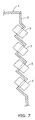
- Fig. 7 an outer panel 2 of equipment 1 is bent and a plurality of, or four in the drawing, adapters 3 of the optical connectors are fixed to the outer panel 2, being inclined downwardly.
- an optical connector 11 according to an embodiment, of the invention comprises an adapter 13 provided through a panel 12 such that the adapter 13 is inclined in the vertical direction, and a plug 14 detachably attached to the adapter 13.
- the adapter 13 is of the tandem type and comprises a pair of adapter bodies 15 and 15' made of a plastic and having the same shape, and two cylindrical adjusting sleeves 16.
- Engaging projections 41 and 41' are provided on sides of the adapter bodies 15 and 15', respectively.
- a pair of first, cantilever engaging terminals 17 or 17' having engaging holes 17A or 17'A at the top and base portions thereof and second cantilever engaging terminals 18 or 18' having engaging projections 18 or 18'A at the top and base portions thereof are provided on the opposite sides of the adapter bodies 15 or 15', respectively.
- the first and second adapter bodies 15 and 15' are joined by the engagement between the engaging holes 17A or 17'A and the engaging projections 18A or 18'A.
- the adjusting sleeves 16 are movably held in sleeve accommodating slots 28 provided in the adapter 15 and 15'.
- Plug engaging cavities 19 are provided in two tiers at the end of each of the adapter bodies 15 and 15'.
- a shield cover 20 made of a metal is provided outside the adapter 13.
- the shield cover 20 has a shape of stepped rectangular parallelepiped and is provided on an outside wall surface of the two connected adapters 13 to shield them integrally.
- Panel fixing members 21 are provided on opposite sides of the shield cover 20 such that the panel fixing members 21 are inclined at a predetermined angle, for example 45°, with respect to the insertion direction of the plug 14.
- Each panel fixing member 21 comprises a panel receiving piece 22 bent outwardly at substantially right angles and a cantilever spring 23 bent slightly outwardly. Accordingly, the adapter 13 and the shield cover 20 are attached to the panel 12 in the inclined condition when the panel 12 is held between the panel receiving piece 22 and the cantilever spring 23.
- Engaging holes 42 and 42' are provided in opposite sides of the shield cover 20 at positions corresponding to the engaging projections 41 and 41' so that the adapter bodies 15 and 15' are held in the shield cover 20 by the engagement between the engaging holes 42 and projection 41.
- each shield cover 20 accommodates two tandem adapters 13 and each adapter 13 is engaged with the plug 14.
- the plug 14 is a twin core plug and comprises two ferules 25 to accommodate an end of a core wire (not shown) of an optical cable 24 and two housings 26 to movably accommodate the ferules 25.
- each of the ferules 25 of the plugs 14 and 14' is aligned and held in the adjusting sleeves 16, and abuts against each other.
- the plugs 14 and 14' are connected to each other through the adapter 13. Since the adapter 13 is installed to the panel 12 on the slant, no that light enters operator's eyes during the connection work of the plugs 14 and 14', thus protecting the operator's eyes. Since a plurality of the adapters 13 are integrally connected with each other, the assembling density is increased, and since the panel 12 does not require the complicated process, such as bending work, the manufacturing of the panel 12 is easy.
- the adapter 13 is attached to the panel 12 by the panel receiving piece 22 and the cantilever spring 23 of the shield cover 20.
- the shield cover 20 may be attached to the panel 14 by a screw, a fixing member other than the shield cover 20 may be employed, or the adapter 13 itself may have a fixing member, such as a screw, to be directly installed to the panel 12.
- the shield cover 20 integrally coves the two adapters 13, however, the shield cover 20 is made to cover each individual adapter 13 as shown in Fig. 3.
- a connecting member 43 and a connecting recess (not shown) engageable with the connecting member 43 are provided on an upper and lower surfaces of the shield cover 20.
- Three or more of the adapters 13 may be integrally shielded by the shield cover 20.
- the adapter 13 may not be of the tandem type.
- the shield cover 20 may be provided on end surfaces 27 of the adapter 13 as well as the peripheral wall surface of the adapter 13.
- the Shape of the shield cover 20 is not limited to the stepped rectangular parallelepiped, but any shape may be employed, which permits the adapter 13 to be installed to the panel 12 at an inclined position with respect to the vertical direction.
- a shield cover 31 is made of a metal and comprises a wedge-shaped adapter receiving cavity 32 for accommodating the adapter 31 and a panel fixing member 33 provided on the lower end of the adapter receiving cavity 32.
- the adapter receiving cavity 32 comprises triangular side surfaces 34, a rectangular upper surface 35, and an end surface 36 corresponding to side surfaces, an upper surface, and an end surface of the adapter 13, respectively.
- the end surface 36 has a pair of openings 37 corresponding to the plug engaging cavities 19.
- the side surfaces 34 have engaging projections 44 to engage with engaging holes 41 so that the adapter 13 is held by the shield cover 31.
- the panel fixing member 33 comprises a predetermined number, or two in the drawings, of projections 38 each having a round hole 39. Accordingly, the adapter 13 and the shield cover 31 are attached to the panel 12, being inclined with respect to the vertical direction by applying screws 40 into the panel 12 through the round holes 39.
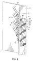
- Fig. 5 four shield covers 31 are connected to each other.
- Fig. 6 the connected shield covers 31 are fixed to the panel 12, and the tandem adapter 13 is inserted into each shield cover 31.
- the plug engaging cavity 19 faces to the panel 12 downwardly on the slant, no light enters operator's eyes, thus protecting the operator's eyes during the assembly work.
- a plurality of the adapters 13 are integrally connected with each other, the assembling density is increased, and since the panel 12 does not require the complicated process, such an bending work, the manufacturing of the panel 12 is made simple.
- the adapter 13 is attached to the panel 12 by tightening the screws through the round holes 39.
- the shield cover 20 may be attached to the panel 14 by a screw, a fixing member other than the shield cover 20 may be employed, or the adapter 13 itself may have a filing member, such as a screw, to be directly installed to the panel 12.
- the shield cover 31 may shield only the peripheral wall surface of the adapter 13 without having the end surface 36.
- the Shape of the shield cover 20 is not limited to the wedge-shape but any shape may be employed, which permits the adapter 13 to be installed to the panel 12 at an inclined position with respect to the vertical direction. A plurality of the shield covers 31 may be integrally made instead of being connected.
- shielding may be provided for a connector that comprises the plug 14' provided inside the panel 12 and fixed to the adapter 13 and a connector section provided outside the panel 12, into or from which the plug 14 is inserted or removed.
- the adapter fixed to the panel is shielded by the shield cover, excellent shield effect is achieved. Since the adapter is inclined with respect to the panel, light does not enter operator's eyes upon insertion and removal of the plug, thus protecting the operator's eyes. Since the connected adapters are installed to the panel, the assembling work is easy and the assembling density is increased. In addition, since the adapter does not require a complicated process, such as bending work, to be fixed to the panel, the process for the panel is simplified.
Abstract
Description
- The present invention relates to an optical connector system, especially to a shield structure of an optical connector system provided in a panel, being inclined with respect to the vertical direction.
- An optical connector has been used in the optical communication system for connecting optical cables or an oplical cable and other optical device for plugging and unplugging. The optical connector is provided on an outer panel of an exchanger, being inclined with respect to the vertical direction so that a laser beam of high output does not enter operator's eyes during the connection work of the optical connector.
- Such an optical connector is described in Japanese Kokai No. 2001-147269. In Fig. 7, an
outer panel 2 of equipment 1 is bent and a plurality of, or four in the drawing,adapters 3 of the optical connectors are fixed to theouter panel 2, being inclined downwardly. - However, in the conventional optical connector, parts of the
outer panel 2, to which theadapters 3 are fixed, are bent, and, therefore, it is difficult to provide the shield of the oplical connector. Also, since theadapters 3 are fixed to the bent parts of theouter panel 2, a space is required between theadapters 3 for fixing theadapters 3, making it difficult to increase the assembling density. In addition, theadapters 3 are fixed to theouter panel 2 individually and the outer panel is required to be bent, the assembling work needs long time. - Accordingly, it is an object of the present invention to provide an optical connector system, which makes the shielding easy, increases the assembling density, and simplifies the fixing and bending works.
- The above object is achieved by the invention as claimed in claim 1.
- Embodiments of the invention will now be described by way of example with respect to the accompanying drawings in which:
- Fig. 1 is an exploded perspective view of a shield structure for an optical connector according to an embodiment of the present invention.
- Fig. 2 is a perspective view of the shield structure.
- Figs. 3 is an exploded perspective view of a shield structure for an optical connector according to a modification to the embodiment of the present invention.
- Figs. 4 and 5 are exploded perspective views of a shield structure for an optical connector according to another embodiment of the present invention.
- Fig. 6 is a perspective view of the shield structure.
- Fig. 7 is a schematic sectional view of a shield structure for an optical connector according to the prior art.
-
- In Figs. 1 and 2, an
optical connector 11 according to an embodiment, of the invention comprises anadapter 13 provided through apanel 12 such that theadapter 13 is inclined in the vertical direction, and aplug 14 detachably attached to theadapter 13. - The
adapter 13 is of the tandem type and comprises a pair ofadapter bodies 15 and 15' made of a plastic and having the same shape, and twocylindrical adjusting sleeves 16.Engaging projections adapter bodies 15 and 15', respectively. A pair of first,cantilever engaging terminals 17 or 17' having engagingholes 17A or 17'A at the top and base portions thereof and secondcantilever engaging terminals 18 or 18' havingengaging projections 18 or 18'A at the top and base portions thereof are provided on the opposite sides of theadapter bodies 15 or 15', respectively. The first andsecond adapter bodies 15 and 15' are joined by the engagement between theengaging holes 17A or 17'A and theengaging projections 18A or 18'A. The adjustingsleeves 16 are movably held in sleeve accommodatingslots 28 provided in theadapter 15 and 15'. Plugengaging cavities 19 are provided in two tiers at the end of each of theadapter bodies 15 and 15'. - A
shield cover 20 made of a metal is provided outside theadapter 13. Theshield cover 20 has a shape of stepped rectangular parallelepiped and is provided on an outside wall surface of the two connectedadapters 13 to shield them integrally.Panel fixing members 21 are provided on opposite sides of theshield cover 20 such that thepanel fixing members 21 are inclined at a predetermined angle, for example 45°, with respect to the insertion direction of theplug 14. Eachpanel fixing member 21 comprises apanel receiving piece 22 bent outwardly at substantially right angles and acantilever spring 23 bent slightly outwardly. Accordingly, theadapter 13 and theshield cover 20 are attached to thepanel 12 in the inclined condition when thepanel 12 is held between thepanel receiving piece 22 and thecantilever spring 23. Engagingholes 42 and 42' are provided in opposite sides of theshield cover 20 at positions corresponding to theengaging projections adapter bodies 15 and 15' are held in theshield cover 20 by the engagement between theengaging holes 42 andprojection 41. - In Fig. 2, two
shield covers 20 are connected in tires and attached to thepanel 12. Eachshield cover 20 accommodates twotandem adapters 13 and eachadapter 13 is engaged with theplug 14. Theplug 14 is a twin core plug and comprises twoferules 25 to accommodate an end of a core wire (not shown) of anoptical cable 24 and twohousings 26 to movably accommodate theferules 25. - When the
plugs 14 are upwardly inserted into theplug engaging cavities 19 outside thepanel 12 and the plugs 14' are downwardly inserted into the plug engaging cavities 19' inside thepanel 12, each of theferules 25 of theplugs 14 and 14' is aligned and held in the adjustingsleeves 16, and abuts against each other. Thus, theplugs 14 and 14' are connected to each other through theadapter 13. Since theadapter 13 is installed to thepanel 12 on the slant, no that light enters operator's eyes during the connection work of theplugs 14 and 14', thus protecting the operator's eyes. Since a plurality of theadapters 13 are integrally connected with each other, the assembling density is increased, and since thepanel 12 does not require the complicated process, such as bending work, the manufacturing of thepanel 12 is easy. - As described above, the
adapter 13 is attached to thepanel 12 by thepanel receiving piece 22 and thecantilever spring 23 of theshield cover 20. However, other method may be used. For example, theshield cover 20 may be attached to thepanel 14 by a screw, a fixing member other than theshield cover 20 may be employed, or theadapter 13 itself may have a fixing member, such as a screw, to be directly installed to thepanel 12. - Also, in the above embodiment, the
shield cover 20 integrally coves the twoadapters 13, however, theshield cover 20 is made to cover eachindividual adapter 13 as shown in Fig. 3. In this case, it is preferable that a connectingmember 43 and a connecting recess (not shown) engageable with the connectingmember 43 are provided on an upper and lower surfaces of theshield cover 20. Three or more of theadapters 13 may be integrally shielded by theshield cover 20. Theadapter 13 may not be of the tandem type. - The
shield cover 20 may be provided onend surfaces 27 of theadapter 13 as well as the peripheral wall surface of theadapter 13. The Shape of theshield cover 20 is not limited to the stepped rectangular parallelepiped, but any shape may be employed, which permits theadapter 13 to be installed to thepanel 12 at an inclined position with respect to the vertical direction. - In the second embodiment shown in Figs. 4-6, the same reference numbers are used for the same elements as those of the first embodiment in Figs. 1 and 2.
- A
shield cover 31 is made of a metal and comprises a wedge-shapedadapter receiving cavity 32 for accommodating theadapter 31 and apanel fixing member 33 provided on the lower end of theadapter receiving cavity 32. Theadapter receiving cavity 32 comprisestriangular side surfaces 34, a rectangularupper surface 35, and anend surface 36 corresponding to side surfaces, an upper surface, and an end surface of theadapter 13, respectively. Theend surface 36 has a pair ofopenings 37 corresponding to theplug engaging cavities 19. Theside surfaces 34 haveengaging projections 44 to engage withengaging holes 41 so that theadapter 13 is held by theshield cover 31. Thepanel fixing member 33 comprises a predetermined number, or two in the drawings, ofprojections 38 each having around hole 39. Accordingly, theadapter 13 and theshield cover 31 are attached to thepanel 12, being inclined with respect to the vertical direction by applyingscrews 40 into thepanel 12 through theround holes 39. - In Fig. 5, four
shield covers 31 are connected to each other. In Fig. 6, the connectedshield covers 31 are fixed to thepanel 12, and thetandem adapter 13 is inserted into eachshield cover 31. In Fig. 5, since theplug engaging cavity 19 faces to thepanel 12 downwardly on the slant, no light enters operator's eyes, thus protecting the operator's eyes during the assembly work. Since a plurality of theadapters 13 are integrally connected with each other, the assembling density is increased, and since thepanel 12 does not require the complicated process, such an bending work, the manufacturing of thepanel 12 is made simple. - As described above, the
adapter 13 is attached to thepanel 12 by tightening the screws through theround holes 39. However, other method may be used. For example, theshield cover 20 may be attached to thepanel 14 by a screw, a fixing member other than theshield cover 20 may be employed, or theadapter 13 itself may have a filing member, such as a screw, to be directly installed to thepanel 12. - The
shield cover 31 may shield only the peripheral wall surface of theadapter 13 without having theend surface 36. The Shape of theshield cover 20 is not limited to the wedge-shape but any shape may be employed, which permits theadapter 13 to be installed to thepanel 12 at an inclined position with respect to the vertical direction.
A plurality of the shield covers 31 may be integrally made instead of being connected. - Instead of shielding the
adapter 13, shielding may be provided for a connector that comprises the plug 14' provided inside thepanel 12 and fixed to theadapter 13 and a connector section provided outside thepanel 12, into or from which theplug 14 is inserted or removed. - According to the present invention, since the adapter fixed to the panel is shielded by the shield cover, excellent shield effect is achieved. Since the adapter is inclined with respect to the panel, light does not enter operator's eyes upon insertion and removal of the plug, thus protecting the operator's eyes. Since the connected adapters are installed to the panel, the assembling work is easy and the assembling density is increased. In addition, since the adapter does not require a complicated process, such as bending work, to be fixed to the panel, the process for the panel is simplified.
Claims (9)
- An optical connector system, comprising;at least one optical connector provided through a panel and inclined with respect to a vertical direction; anda shield cover provided outside said oplical connector.
- The optical connector system according to claim 1, wherein said optical connector is fixed to said panel by said shield cover.
- The optical connector system according to claim 1, wherein a plurality of said optical connectors are connected with each other in a shape of step and said shield cover integrally shields said connected oplical connectors.
- The optical connector system according to claim 2, wherein said plurality of oplical connectors are connected with each other in a shape of step and said shield cover integrally shields said connected optical connectors.
- The optical connector system according to one of claims 1-4, wherein said shield cover is provided such that it goes through said panel with said optical connector.
- The optical connector system according to claim 1 or 2, wherein said shield cover has a shape of stepped rectangular parallelepiped and is provided on at least an outside wall surface of said optical connector.
- The optical connector system according to claim 1. or 2, wherein said shield cover is provided on at least an outside wall surface of one side of said optical connector, said one side projecting from said panel.
- The optical connector system according to claim 6, wherein said shield cover is further provided on an end surface of said optical connector.
- The oplical connector according to claim 7, wherein said shield cover is further provided on an end surface of said optical connector.
Applications Claiming Priority (2)
| Application Number | Priority Date | Filing Date | Title |
|---|---|---|---|
| JP2001281247A JP3921063B2 (en) | 2001-09-17 | 2001-09-17 | Optical connector shield structure |
| JP2001281247 | 2001-09-17 |
Publications (3)
| Publication Number | Publication Date |
|---|---|
| EP1298470A2 true EP1298470A2 (en) | 2003-04-02 |
| EP1298470A3 EP1298470A3 (en) | 2004-05-19 |
| EP1298470B1 EP1298470B1 (en) | 2008-07-16 |
Family
ID=19105107
Family Applications (1)
| Application Number | Title | Priority Date | Filing Date |
|---|---|---|---|
| EP02020809A Expired - Fee Related EP1298470B1 (en) | 2001-09-17 | 2002-09-17 | Optical connector system |
Country Status (4)
| Country | Link |
|---|---|
| US (1) | US6840681B2 (en) |
| EP (1) | EP1298470B1 (en) |
| JP (1) | JP3921063B2 (en) |
| DE (1) | DE60227627D1 (en) |
Cited By (1)
| Publication number | Priority date | Publication date | Assignee | Title |
|---|---|---|---|---|
| WO2009120523A1 (en) * | 2008-03-28 | 2009-10-01 | Adc Telecommunications, Inc. | Adapter plate with angled openings and method of manufacture |
Families Citing this family (6)
| Publication number | Priority date | Publication date | Assignee | Title |
|---|---|---|---|---|
| WO2004052066A1 (en) * | 2002-11-29 | 2004-06-17 | Fujitsu Limited | Unit mounted on electronic device and connection mechanism of transmission line of the electronic device |
| US7136555B2 (en) * | 2004-05-27 | 2006-11-14 | Corning Cable Systems Llc | Distribution cable having articulated optical connection nodes |
| US20070265583A1 (en) * | 2006-05-10 | 2007-11-15 | General Electric Company | Catheter input device |
| JP2008046592A (en) * | 2007-03-06 | 2008-02-28 | Sanwa Denki Kogyo Co Ltd | Optical connector interconnection adaptor |
| US7867022B2 (en) * | 2009-04-08 | 2011-01-11 | Tyco Electronics Corporation | Brackets and receptacle assemblies with angled ports |
| JP5973745B2 (en) * | 2011-03-31 | 2016-08-23 | 住友電気工業株式会社 | Optical transceiver |
Citations (5)
| Publication number | Priority date | Publication date | Assignee | Title |
|---|---|---|---|---|
| US5708742A (en) * | 1996-06-18 | 1998-01-13 | Northern Telecom Limited | Combinations of printed circuit boards and face plates |
| EP0927899A1 (en) * | 1998-01-05 | 1999-07-07 | Molex Incorporated | Fiber optic termination system including a fiber optic connector assembly and method of fabricating same |
| US6066001A (en) * | 1998-11-30 | 2000-05-23 | 3Com Corporation | Coupler for minimizing EMI emissions |
| US6160946A (en) * | 1998-07-27 | 2000-12-12 | Adc Telecommunications, Inc. | Outside plant fiber distribution apparatus and method |
| WO2001040839A1 (en) * | 1999-12-01 | 2001-06-07 | 3M Innovative Properties Company | Optical fiber connector systems |
Family Cites Families (8)
| Publication number | Priority date | Publication date | Assignee | Title |
|---|---|---|---|---|
| US5121454A (en) * | 1989-11-24 | 1992-06-09 | Nippon Telegraph And Telephone Corporation | Optical connector |
| US5142606A (en) * | 1990-01-22 | 1992-08-25 | Porta Systems Corp. | Optical fiber cable distribution frame and support |
| EP0463749A3 (en) * | 1990-06-04 | 1993-02-24 | Bicc Public Limited Company | Termination system of optical fibres |
| US5601451A (en) * | 1994-03-28 | 1997-02-11 | Amphenol Corporation | Combination connector |
| US6601995B1 (en) * | 2000-06-02 | 2003-08-05 | Cisco Technology, Inc | Optical connector with flexible shielding cover |
| JP2002365487A (en) * | 2001-01-18 | 2002-12-18 | Auto Network Gijutsu Kenkyusho:Kk | Optical connector and shielding case for optical connector |
| JP2002221644A (en) * | 2001-01-26 | 2002-08-09 | Auto Network Gijutsu Kenkyusho:Kk | Optical connector and structure of mounting part of optical connector |
| US6621974B1 (en) * | 2001-11-28 | 2003-09-16 | Max Chu | Fiber converter box |
-
2001
- 2001-09-17 JP JP2001281247A patent/JP3921063B2/en not_active Expired - Fee Related
-
2002
- 2002-09-16 US US10/243,922 patent/US6840681B2/en not_active Expired - Fee Related
- 2002-09-17 DE DE60227627T patent/DE60227627D1/en not_active Expired - Fee Related
- 2002-09-17 EP EP02020809A patent/EP1298470B1/en not_active Expired - Fee Related
Patent Citations (5)
| Publication number | Priority date | Publication date | Assignee | Title |
|---|---|---|---|---|
| US5708742A (en) * | 1996-06-18 | 1998-01-13 | Northern Telecom Limited | Combinations of printed circuit boards and face plates |
| EP0927899A1 (en) * | 1998-01-05 | 1999-07-07 | Molex Incorporated | Fiber optic termination system including a fiber optic connector assembly and method of fabricating same |
| US6160946A (en) * | 1998-07-27 | 2000-12-12 | Adc Telecommunications, Inc. | Outside plant fiber distribution apparatus and method |
| US6066001A (en) * | 1998-11-30 | 2000-05-23 | 3Com Corporation | Coupler for minimizing EMI emissions |
| WO2001040839A1 (en) * | 1999-12-01 | 2001-06-07 | 3M Innovative Properties Company | Optical fiber connector systems |
Cited By (3)
| Publication number | Priority date | Publication date | Assignee | Title |
|---|---|---|---|---|
| WO2009120523A1 (en) * | 2008-03-28 | 2009-10-01 | Adc Telecommunications, Inc. | Adapter plate with angled openings and method of manufacture |
| US7978951B2 (en) | 2008-03-28 | 2011-07-12 | Adc Telecommunications, Inc. | Bulkhead with angled openings and method |
| US8494330B2 (en) | 2008-03-28 | 2013-07-23 | Adc Telecommunications, Inc. | Bulkhead with angled openings and method |
Also Published As
| Publication number | Publication date |
|---|---|
| EP1298470B1 (en) | 2008-07-16 |
| US20030053760A1 (en) | 2003-03-20 |
| DE60227627D1 (en) | 2008-08-28 |
| US6840681B2 (en) | 2005-01-11 |
| EP1298470A3 (en) | 2004-05-19 |
| JP2003090932A (en) | 2003-03-28 |
| JP3921063B2 (en) | 2007-05-30 |
Similar Documents
| Publication | Publication Date | Title |
|---|---|---|
| US10495817B2 (en) | Connector system with physical security feature | |
| CA2282055C (en) | Arrangement for integrating a rectangular fiber optic connector into a cylindrical connector | |
| CN102087392B (en) | Fiber optic splitter module | |
| US6398422B1 (en) | Dual-function dust cover | |
| KR100248970B1 (en) | Adapter assembly for fiber optic connectors | |
| JPH087308B2 (en) | Fiber Optic Duplex Connector Assembly | |
| HU216984B (en) | Fiber optic connector | |
| KR20040104689A (en) | Hybrid plug connector | |
| US6741783B2 (en) | Optical cable adapter or connector | |
| US6751392B1 (en) | Cable management system for connector assemblies | |
| US8807843B2 (en) | Connector system with physical security feature | |
| US6840681B2 (en) | Tandem type optical connector | |
| EP1310812B1 (en) | Optical connector system | |
| EP1256828A2 (en) | Connector device and connector | |
| JP2002116350A (en) | Adaptor or receptacle for optical cable | |
| US6575639B2 (en) | Optical adapter | |
| US20050058401A1 (en) | Keyed adapter and connector | |
| JPH04104111A (en) | Optical connector |
Legal Events
| Date | Code | Title | Description |
|---|---|---|---|
| PUAI | Public reference made under article 153(3) epc to a published international application that has entered the european phase |
Free format text: ORIGINAL CODE: 0009012 |
|
| AK | Designated contracting states |
Designated state(s): AT BE BG CH CY CZ DE DK EE ES FI FR GB GR IE IT LI LU MC NL PT SE SK TR Kind code of ref document: A2 Designated state(s): AT BE BG CH CY CZ DE DK EE ES FI FR GB GR IE IT LI LU MC NL PT SE SK TR |
|
| AX | Request for extension of the european patent |
Extension state: AL LT LV MK RO SI |
|
| PUAL | Search report despatched |
Free format text: ORIGINAL CODE: 0009013 |
|
| AK | Designated contracting states |
Kind code of ref document: A3 Designated state(s): AT BE BG CH CY CZ DE DK EE ES FI FR GB GR IE IT LI LU MC NL PT SE SK TR |
|
| AX | Request for extension of the european patent |
Extension state: AL LT LV MK RO SI |
|
| 17P | Request for examination filed |
Effective date: 20040812 |
|
| AKX | Designation fees paid |
Designated state(s): DE FR GB IT |
|
| 17Q | First examination report despatched |
Effective date: 20050407 |
|
| 17Q | First examination report despatched |
Effective date: 20050407 |
|
| GRAP | Despatch of communication of intention to grant a patent |
Free format text: ORIGINAL CODE: EPIDOSNIGR1 |
|
| GRAS | Grant fee paid |
Free format text: ORIGINAL CODE: EPIDOSNIGR3 |
|
| GRAA | (expected) grant |
Free format text: ORIGINAL CODE: 0009210 |
|
| AK | Designated contracting states |
Kind code of ref document: B1 Designated state(s): DE FR GB IT |
|
| REG | Reference to a national code |
Ref country code: GB Ref legal event code: FG4D |
|
| REF | Corresponds to: |
Ref document number: 60227627 Country of ref document: DE Date of ref document: 20080828 Kind code of ref document: P |
|
| PGFP | Annual fee paid to national office [announced via postgrant information from national office to epo] |
Ref country code: DE Payment date: 20080930 Year of fee payment: 7 |
|
| PLBE | No opposition filed within time limit |
Free format text: ORIGINAL CODE: 0009261 |
|
| STAA | Information on the status of an ep patent application or granted ep patent |
Free format text: STATUS: NO OPPOSITION FILED WITHIN TIME LIMIT |
|
| 26N | No opposition filed |
Effective date: 20090417 |
|
| GBPC | Gb: european patent ceased through non-payment of renewal fee |
Effective date: 20081016 |
|
| PG25 | Lapsed in a contracting state [announced via postgrant information from national office to epo] |
Ref country code: GB Free format text: LAPSE BECAUSE OF NON-PAYMENT OF DUE FEES Effective date: 20081016 |
|
| PG25 | Lapsed in a contracting state [announced via postgrant information from national office to epo] |
Ref country code: DE Free format text: LAPSE BECAUSE OF NON-PAYMENT OF DUE FEES Effective date: 20100401 |
|
| PGFP | Annual fee paid to national office [announced via postgrant information from national office to epo] |
Ref country code: FR Payment date: 20130910 Year of fee payment: 12 |
|
| PGFP | Annual fee paid to national office [announced via postgrant information from national office to epo] |
Ref country code: IT Payment date: 20130910 Year of fee payment: 12 |
|
| REG | Reference to a national code |
Ref country code: FR Ref legal event code: ST Effective date: 20150529 |
|
| PG25 | Lapsed in a contracting state [announced via postgrant information from national office to epo] |
Ref country code: IT Free format text: LAPSE BECAUSE OF NON-PAYMENT OF DUE FEES Effective date: 20140917 Ref country code: FR Free format text: LAPSE BECAUSE OF NON-PAYMENT OF DUE FEES Effective date: 20140930 |