EP1297965B1 - Media cartridge with printed circuit board for use in a printing system - Google Patents
Media cartridge with printed circuit board for use in a printing system Download PDFInfo
- Publication number
- EP1297965B1 EP1297965B1 EP02256285A EP02256285A EP1297965B1 EP 1297965 B1 EP1297965 B1 EP 1297965B1 EP 02256285 A EP02256285 A EP 02256285A EP 02256285 A EP02256285 A EP 02256285A EP 1297965 B1 EP1297965 B1 EP 1297965B1
- Authority
- EP
- European Patent Office
- Prior art keywords
- media
- media cartridge
- printed circuit
- circuit board
- printing machine
- Prior art date
- Legal status (The legal status is an assumption and is not a legal conclusion. Google has not performed a legal analysis and makes no representation as to the accuracy of the status listed.)
- Expired - Fee Related
Links
Images


Classifications
-
- H—ELECTRICITY
- H05—ELECTRIC TECHNIQUES NOT OTHERWISE PROVIDED FOR
- H05K—PRINTED CIRCUITS; CASINGS OR CONSTRUCTIONAL DETAILS OF ELECTRIC APPARATUS; MANUFACTURE OF ASSEMBLAGES OF ELECTRICAL COMPONENTS
- H05K1/00—Printed circuits
- H05K1/02—Details
- H05K1/0266—Marks, test patterns or identification means
-
- B—PERFORMING OPERATIONS; TRANSPORTING
- B41—PRINTING; LINING MACHINES; TYPEWRITERS; STAMPS
- B41J—TYPEWRITERS; SELECTIVE PRINTING MECHANISMS, i.e. MECHANISMS PRINTING OTHERWISE THAN FROM A FORME; CORRECTION OF TYPOGRAPHICAL ERRORS
- B41J11/00—Devices or arrangements of selective printing mechanisms, e.g. ink-jet printers or thermal printers, for supporting or handling copy material in sheet or web form
- B41J11/009—Detecting type of paper, e.g. by automatic reading of a code that is printed on a paper package or on a paper roll or by sensing the grade of translucency of the paper
-
- B—PERFORMING OPERATIONS; TRANSPORTING
- B41—PRINTING; LINING MACHINES; TYPEWRITERS; STAMPS
- B41J—TYPEWRITERS; SELECTIVE PRINTING MECHANISMS, i.e. MECHANISMS PRINTING OTHERWISE THAN FROM A FORME; CORRECTION OF TYPOGRAPHICAL ERRORS
- B41J15/00—Devices or arrangements of selective printing mechanisms, e.g. ink-jet printers or thermal printers, specially adapted for supporting or handling copy material in continuous form, e.g. webs
- B41J15/04—Supporting, feeding, or guiding devices; Mountings for web rolls or spindles
- B41J15/044—Cassettes or cartridges containing continuous copy material, tape, for setting into printing devices
-
- B—PERFORMING OPERATIONS; TRANSPORTING
- B41—PRINTING; LINING MACHINES; TYPEWRITERS; STAMPS
- B41J—TYPEWRITERS; SELECTIVE PRINTING MECHANISMS, i.e. MECHANISMS PRINTING OTHERWISE THAN FROM A FORME; CORRECTION OF TYPOGRAPHICAL ERRORS
- B41J17/00—Mechanisms for manipulating page-width impression-transfer material, e.g. carbon paper
- B41J17/36—Alarms, indicators, or feed-disabling devices responsible to material breakage or exhaustion
-
- H—ELECTRICITY
- H05—ELECTRIC TECHNIQUES NOT OTHERWISE PROVIDED FOR
- H05K—PRINTED CIRCUITS; CASINGS OR CONSTRUCTIONAL DETAILS OF ELECTRIC APPARATUS; MANUFACTURE OF ASSEMBLAGES OF ELECTRICAL COMPONENTS
- H05K1/00—Printed circuits
- H05K1/02—Details
- H05K1/0286—Programmable, customizable or modifiable circuits
- H05K1/029—Programmable, customizable or modifiable circuits having a programmable lay-out, i.e. adapted for choosing between a few possibilities
-
- H—ELECTRICITY
- H05—ELECTRIC TECHNIQUES NOT OTHERWISE PROVIDED FOR
- H05K—PRINTED CIRCUITS; CASINGS OR CONSTRUCTIONAL DETAILS OF ELECTRIC APPARATUS; MANUFACTURE OF ASSEMBLAGES OF ELECTRICAL COMPONENTS
- H05K1/00—Printed circuits
- H05K1/02—Details
- H05K1/0286—Programmable, customizable or modifiable circuits
- H05K1/0293—Individual printed conductors which are adapted for modification, e.g. fusable or breakable conductors, printed switches
-
- H—ELECTRICITY
- H05—ELECTRIC TECHNIQUES NOT OTHERWISE PROVIDED FOR
- H05K—PRINTED CIRCUITS; CASINGS OR CONSTRUCTIONAL DETAILS OF ELECTRIC APPARATUS; MANUFACTURE OF ASSEMBLAGES OF ELECTRICAL COMPONENTS
- H05K2201/00—Indexing scheme relating to printed circuits covered by H05K1/00
- H05K2201/10—Details of components or other objects attached to or integrated in a printed circuit board
- H05K2201/10007—Types of components
- H05K2201/10181—Fuse
-
- H—ELECTRICITY
- H05—ELECTRIC TECHNIQUES NOT OTHERWISE PROVIDED FOR
- H05K—PRINTED CIRCUITS; CASINGS OR CONSTRUCTIONAL DETAILS OF ELECTRIC APPARATUS; MANUFACTURE OF ASSEMBLAGES OF ELECTRICAL COMPONENTS
- H05K2203/00—Indexing scheme relating to apparatus or processes for manufacturing printed circuits covered by H05K3/00
- H05K2203/17—Post-manufacturing processes
- H05K2203/175—Configurations of connections suitable for easy deletion, e.g. modifiable circuits or temporary conductors for electroplating; Processes for deleting connections
Definitions
- This invention pertains to the field of printing systems. More specifically, this invention pertains to the field of media cartridges for printers, such as label roll printers.
- Label roll printers are utilized in order to create customized labels for home or office purposes.
- the growing demand for customized labels in recent years has increased the use of these printers.
- label roll printer systems have been comprised of a media cartridge and a printing machine.
- the media cartridge may contain a media source, such as a roll of labels, and some sort of a media support assembly.
- the printing machine is often comprised of a housing, a processing unit with an operating system, and a printing mechanism.
- EP0927639 discloses a printing apparatus and printing method utilising a fuse pattern mounted on the side of the cartridge for information writing.
- EP0927639 discloses a printing apparatus and printing method utilising a fuse pattern mounted on the side of the cartridge for information writing.
- these prior art printing systems enable their printing machines to recognize a number of different types of media cartridges as explained above, most do not create an individual identification parameter, such as a serial number, for identifying each media cartridge regardless of its media type.
- the present invention is a printing system comprising of a media cartridge as defined in claim 1 and a printing machine as defined in claim 2.
- the media cartridge is preferably comprised of a media source and a printed circuit board having a plurality of conductive traces with fusible links that form a circuit pattern on first and second slides of the printed circuit board.
- the fusible links encode information about the media cartridge.
- the fusible links may encode a media type number that contains information about the type of media source used in the media cartridge.
- the fusible links may encode a serial number specific to the media cartridge that enables it to be individually identified by the printing machine.
- the printing machine is preferably comprised of a housing, a processing unit and a printing mechanism connected to the housing, a media cartridge interface connecting the printing machine to the media cartridge, and a look-up table.
- the look-up table may be comprised of the media type number for each media cartridge that has been attached to the printing machine.
- the look-up table may be comprised of the individual serial numbers for each of these media cartridges.
- the look-up table may also keep track of the amount of media used within individual media cartridges. Also, the look-up table may keep track of user settings associated with an individual media cartridge.
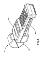
- FIG. 1 shows an exemplary printing system 8 of the present invention.
- the printing system 8 preferably comprises a media cartridge 10 that is inserted into a housing 152 of a printing machine 150.
- a label roll is shown in FIG. 1 as the media source for the media cartridge 10, it should be understood that any type of media source, including media sources other than label rolls (e.g., label sheets, photograph paper, etc.), may be used with the printing system of the present invention.
- a label roll printer is shown in FIG. 1 as the printing machine 150, it should also be understood that any type of printing machine, including printing machines other than label roll printers (e.g., laser printers, photograph printers, etc.), may be used with the printing system of the present invention.
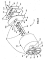
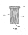
- FIG. 2 illustrates an exploded view of an exemplary embodiment of the media cartridge 10.
- the media cartridge 10 comprises a printed circuit board assembly 20, a media support assembly 70, a media source 130, and a pair of fasteners 140.
- the printed circuit board assembly 20 comprises a printed circuit board 30 and a printed circuit board cover 50.
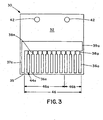
- FIG. 3 shows an example of the printed circuit board 30 in greater detail.
- the printed circuit board 30 has a first side 32, a second side 34 (see FIG. 4 ), a connection edge 35, and a pair of fastener holes 42.
- the first side 32 of the printed circuit board 30 preferably has a plurality of conductive traces 36a with fusible links 38a that are connected together to form a circuit pattern 44a. It should be understood that while twelve conductive traces 36a are shown in the printed circuit board 30 of FIG. 3 , more or less conductive traces 36a may be used with the printed circuit board of the present invention, depending on consumer and/or manufacturing preferences. As shown in FIG.
- the fusible links 38a are also connected together by a common conductive trace 39a, which in turn is also connected to a common conductive trace 37a.
- the plurality of conductive traces 36a and the common conductive trace 37a are all in communication with the connection edge 35 of the printed circuit board 30.
- the circuit pattern 44a (and its plurality of conductive traces 36a and fusible links 38a) preferably has an encoding for one or more parameters 46 associated with the media cartridge 10 that includes the corresponding printed circuit board 30, as shown in FIG. 3 .
- each conductive trace 36a of the circuit pattern 44a preferably represents a bit integer (i.e., 1 or 0), and the collection of conductive traces 36a represent a binary number, which in turn may be translated into a numerical value for the parameter 46.
- the circuit pattern may include an encoding for a single parameter 46, or alternatively, may include an encoding for two or more parameters, such as a media type number 46a and a serial number 46b.
- the media type number 46a may be encoded via eight conductive traces 36a (i.e., an eight bit number) of the circuit pattern 44a, while the serial number 46b may be encoded via the remaining four conductive traces 36a (i.e., a four bit number) of the circuit pattern 44a.
- the media type number 46a and the serial number 46b may be comprised of any length bit number depending on the number of conductive traces used in the relative circuit pattern.
- the media type number 46a (or 46a') is used to describe the media source 130 used in the media cartridge 10.
- the media source 130 is comprised of a roll of labels, so the media type number 46a may encode a numerical value that identifies the type of label contained in the media source 130.
- the serial number 46b (or 46b') is preferably used to identify a particular media cartridge 10 independent of its media type. In other words, such a serial number could make a specific media cartridge 10 individually recognizable to the printing machine 150.
- the printing machine is preferably capable of "remembering" a media cartridge and its characteristics (e.g., amount of labels remaining) even if it has been removed and later reinserted into the printing machine.
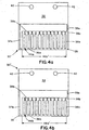
- FIGS. 4a-4b An exemplary embodiment of a printed circuit board 30' for use with the media cartridge 10 of the present invention is shown in FIGS. 4a-4b .
- the printed circuit board 30' is identical to the printed circuit board 30 described above and shown in FIG. 3 , except that both the first and second sides 32, 34 of the printed circuit board 30' have circuit patterns 44a, 44b, with the circuit patterns 44a, 44b of the printed circuit board 30' both including an encoding for media cartridge parameters, such as a media type number 46a' and a serial number 46b'.
- the second side 34 is preferably, but not necessarily, identical to the first side 32, except that its parameter 46b' may be used for different purpose (i.e., a serial number) than the parameter 46a' (i.e., a media type number).
- corresponding components of the second side 34 have been referenced with a "b" in FIG. 4b , instead of the "a" used in FIG. 4a .
- the conductive traces 36a and the fusible links 38a of the first side 32 of the printed circuit board have been referenced as the conductive traces 36b and the fusible links 38b for the second side 34 of the printed circuit board.
- the "a” and “b” components in FIGS. 4a and 4b are preferably identical (except for the parameters 46a' and 46b') unless otherwise stated to the contrary herein.
- the circuit pattern 44a of the first side 32 of the printed circuit board 30' may include an encoding for a twelve bit media type number 46a'
- the circuit pattern 44b of the second side 34 of the printed circuit board 30' may include an encoding for a twelve bit serial number 46b'.
- FIG. 5 details the electrical interconnections of one possible circuit pattern for a printed circuit board of the present invention, regardless of which embodiment is employed for the printed circuit board. For exemplary purposes, however, only the circuit pattern 44a of FIG. 4a is shown in FIG. 5 and will described herein. It should be understood that the same electrical interconnections may be applied to the circuit patterns 44a, 44b (or portions thereof) of FIGS. 3 and 4b .
- the circuit pattern 44a on the first side 32 may be formed by blowing open or breaking one or more of the fusible links 38a.
- the fusible links may be blown or broken in the following manner. First, a high voltage may be applied to one or more of the conductive traces 36a while grounding the common conductive trace 37a. As a result, a large current may pass through one or more of the fusible links 38a connected to the conductive traces 36a that had the voltage applied to them. This large current then blows or breaks the one or more fusible links 38a it passes through, preventing any future current from passing through those one or more fusible links 38a.
- the one or more fusible links 38a through which the high current passed will now be part of an open circuit.
- the fusible links 38a may be blown or broken by the printed circuit board manufacturer or by the printing system that incorporates the printed circuit board, as discussed in more detail below.
- each conductive trace (Conductive traces A-L) is labeled with a numerical value corresponding to its bit position within the binary number encoded in the circuit pattern 44a.
- Conductive trace A is assigned a numerical value of "1" (i.e., 2 0 )
- Conductive trace B is assigned a numerical value of "2" (i.e., 2 1 )
- Conductive trace C is assigned a numerical value of "4" (i.e., 2 2 ), and so on, with the number of possible combinations of encoded numerical values for the circuit pattern being directly proportional to the number of conductive traces 36a (e.g., Conductive traces A-L).
- there are 2 N possible combinations of encoded numerical values for the circuit pattern where "N" is the number of conductive traces 36a used to form the circuit pattern.
- the circuit pattern 44a may encode a bit pattern (not shown).
- This bit pattern comprises a string of logical low and high values.
- the blown or broken (i.e., open circuit) fusible links 38a correspond to logical high values (i.e., a binary "1")
- the non-blown or unbroken (i.e., closed circuit) fusible links 38a correspond to logical low values (i.e., a binary "0").
- each circuit pattern 44a, 44b may encode more or less data, or different data altogether, and that this description is merely illustrating an exemplary embodiment of this invention. Also, unlike the exemplary embodiment shown in FIG. 4a-4b , in other alternate embodiments, only one side or a portion thereof may have a circuit pattern. Furthermore, in alternate embodiments, it is also possible that both sides or portions thereof may have a substantially similar circuit pattern.
- the printed circuit board cover 50 which houses the printed circuit board 30 comprises a first side 54, a second side 56, and a third side 58 all preferably connected together and extending from a base 52.
- the printed circuit board cover 50 also includes an opening 60 between the first and third sides 54, 58, and a fastener connection area 62 with a pair of connection holes 63.
- the connection holes 63 are preferably aligned with the fastener holes 42 of the printed circuit board 30 (or 30').
- the fasteners 140 align and connect the printed circuit board cover 50 to the printed circuit board 30 (or 30').
- the design shown in FIG. 2 for the printed circuit board cover 50 is merely exemplary, and alternate designs for covers that protect the printed circuit board 30 may be utilized.
- the printed circuit board cover 50 is preferably made from a polymer plastic such as polypropylene, polyurethane, or polyvinyl chloride, other suitable materials may be used for the printed circuit board 50, depending on consumer and/or manufacturing preferences.
- the media support assembly 70 is preferably (but not necessarily) comprised of a media support 80, a fixed support plate 90, and an adjustable support plate 110.
- the media support 80 is comprised of an outer surface 82, a first end 84, a second end 86, and a male fastener connection area 88.
- the male fastener connection area 88 is located at the first end 84 of the media support 80, but may be located elsewhere in alternate embodiments, such as between the first end 84 and the second end 86.
- the fixed support plate 90 is preferably comprised of a first side 92, a second side 94, a female fastener connection area 96, and a fingerplate 102 (see FIG. 6 ).
- the fingerplate 102 is preferably connected to the second side 94 of the fixed support plate 90.
- the fingerplate 102 provides a convenient place to grasp the fixed support plate 90.
- the female fastener connection area 96 is present on both the first side 92 and the second side 94 of the fixed support plate 90. As best shown in FIG.
- the female fastener connection area 96 preferably contains a recessed portion 96a for receiving the male fastener connection area 88 of the media support 80, and a pair of support holes 96b aligned with the fastener holes 42 and the connection holes 63 for receiving the fasteners 140. Consequently, the male fastener connection area 88 may be mated with the recessed portion 96a of the female fastener connection area 96 to connect the media support 80 and the fixed support plate 90, and the fasteners 140 may be passed through the connection, fastener, and support holes 63, 42, 96b to connect the printer circuit board cover 50, the printed circuit board 30, the fixed support plate 90, and the media support 80 together.
- the adjustable support plate 110 is comprised of a first side 112, a second side 114, a central bore 116, a central bore inner surface 118, a first finger tab 120, and a second finger tab 122.
- the first finger tab 120 and the second finger tab 122 are preferably connected to the first side 112 of the adjustable support plate 110.
- the first finger tab 120 and the second finger tab 122 serve as a convenient place to grasp the adjustable support plate 110.
- the central bore 116 passes through the adjustable support plate 110 from the first side 112 to the second side 114.
- the central bore inner surface 118 preferably has dimensions corresponding to the outer surface 82 of the media support 80.
- the central bore inner surface 118 can be removably mounted on the outer surface 82 of the media support 80 near its second end 86 to removably connect the adjustable support plate 110 to the media support 80 (and thus the fixed support plate 90).
- the material used for all of the components in the media support assembly 70 is preferably a polymer plastic, such as polypropylene, polyurethane, or polyvinyl chloride.
- a polymer plastic such as polypropylene, polyurethane, or polyvinyl chloride.
- the printed circuit board cover 50 it should be understood that other suitable materials may be used for such components, depending on consumer and/or manufacturing preferences.
- the media source 130 is preferably comprised of a central bore 132, and a central bore inner surface 134.
- the central bore inner surface 134 preferably has dimensions larger than the outer surface 82 of the media support 80.
- the central bore inner surface 134 can be removably mounted on the outer surface 82 of the media support 80.
- the media source 130 is a roll of labels, but different types of media may be used in alternate embodiments of the present invention.
- the media source 130 may be a stack of papers or photographs, or a roll of another type of printable media.
- the media support 80 may be more in the form of a tray for holding and supporting media, as opposed to the rod-like configuration shown in FIG. 2 .
- FIG. 2 also shows a pair of fasteners 140, more specifically a first fastener 142 and a second fastener 144, which have been referred to above.
- the fasteners may be metal screws. It should be understood, however, that other types of fasteners, such as nails, bolts, rivets, tabs, and snap-fit components, may be used with the media cartridge of the present invention, depending on consumer and/or manufacturing preferences.
- the exemplary printing machine 150 comprises a processing unit 168 that is connected to and in communication with a printing mechanism 154, a media cartridge interface 160, a memory unit 178, and a user interface 198.
- the processing unit 168 is further comprised of an automated programming mechanism 170
- the memory unit 178 is further comprised of a look-up table 180 and a counter 197.
- the printing mechanism 154 is the mechanical mechanism by which the printing machine 150 prints.
- the printing mechanism is a thermal printing mechanism.
- a thermal printing mechanism is generally comprised of a fixed linear array of heating elements designed to make direct contact with thermally sensitive media. It should be understood, however, that alternate embodiments are also possible, and the printing mechanism 154 may, for example, be a dot matrix printing mechanism or a laser printing mechanism.
- U.S. Patent Nos. 3,965,330 and 3,947,854 U.S. Patent Nos. 3,965,330 and 3,947,854 .
- the media cartridge interface 160 is comprised of a first end 162, a second end 164, and a wire band 166 connecting the first and second ends 162, 164.
- the first end 162 of the media cartridge interface 160 is designed to connect to the connection edge 35 of the printed circuit board 30 through the opening 60 in the printed circuit board cover 50.
- the media cartridge interface 160 preferably contacts, and is capable of reading the encoding of, the circuit pattern 44a and its plurality of conductive traces 36a.
- the second end 164 of the media cartridge interface 160 is designed to connect to the processing unit 168 on the printing machine 160. Therefore, the media cartridge interface 160 connects the printed circuit board 30 to the printing machine 150. While a wire band 166 is shown in the exemplary embodiment of FIG. 8 , however, it should be understood that the wire band is not necessary, and the second end 164 of the media cartridge interface may be mounted directly to, and formed integral with, the housing of the printing machine.
- the media cartridge interface 160 is a simple off-the-shelf card edge connector, but any device known to form an interface with printed circuit boards may be used.
- any device known to form an interface with printed circuit boards may be used.
- U.S. Patents Nos. 6,254,435 and 6,174,184 which pertain to card edge connectors.
- U.S. Patents Nos. 6,254,435 and 6,174,184 are examples of card edge connectors.
- the processing unit 168 of the printing machine 150 is a microprocessor running a proprietary operating system. Generally, computational processes that take place within the printing machine 150 take place in the processing unit 168. Furthermore, the processing unit 168 connects to and controls the printing mechanism 154, the media cartridge interface 160, the memory unit 178, and the user interface 198. In this exemplary embodiment, the parameters 46 of the printed circuit board 30, such as the media type number 46a and/or the serial number 46b, are received at the printing machine 150 by the processing unit 168 via the media cartridge interface 160. It should be understood that the preceding description of the processing unit is only exemplary, and one of ordinary skill in the art would be able to contemplate other alternate embodiments without departing from the scope and spirit of the present invention.
- the processing unit 168 is further comprised of an automated programming mechanism 170, which may be used to fuse program the printed circuit board 30.
- the automated programming mechanism 170 is a device that sends a high current across the media cartridge interface 160 through one of more of the conductive traces 36a and/or the conductive traces 36b in order to blow or break one or more of the fusible links 38a and/or fusible links 38b, respectively. Fusible links 38a and/or fusible links 38b are sized to require a small amount of current to melt or vaporize the link. The method of operation of such a device as the automated programming mechanism 170 has been explained earlier when discussing the printed circuit board 30.
- FIG. 7 also shows the exemplary memory unit 178.
- the memory unit 178 is preferably a non-volatile memory device such that memory values will not be lost when the printing machine is powered off.
- the memory unit 178 is electronically connected to the processing unit 168, and is also physically contained in the housing 152 of the printing machine 150.
- a look-up table 180 may be stored in the memory unit 178.
- the look-up table 180 is a first-in-first-out (FIFO) storage table that is comprised of a set of row entries 182, as shown in FIG. 9 .
- FIFO first-in-first-out
- each row entry in the set of row entries 182 is comprised of one column entry from each of the following column arrays: an index array 184, a media type number array 186, a serial number array 188, a starting media amount array 190, and a remaining media amount array 192.
- an index array 184 an index array 184
- a media type number array 186 an index array 184
- a serial number array 188 an index array 184
- a starting media amount array 190 a remaining media amount array 192.
- a remaining media amount array 192 To simplify the analysis of the look-up table 180, one can examine a sample row entry 194 in light of each exemplary column array in closer detail.
- the index array 184 keeps track of the number of entries in the look-up table 180.
- the processing unit 168 is the unit that updates and modifies the index array 184.
- the corresponding value in the index array 184 is "6.” Therefore, in this exemplary embodiment, the sample row entry 194 is the sixth row entry in the set of row entries 182.
- Each entry in the media type number array 186 identifies the type of media source 130 present in a media cartridge 10 that has been loaded into the printing machine 150.
- each entry in this array is a media type number 46a (or 46a') that was sent from the printed circuit board 30 to the look-up table 180 via the media cartridge interface 160 and the processing unit 168.
- FIG. 9 shows that the media type number 46a corresponding to the sample row entry 194 is "10.” This value of "10" may be used to indicate that the media source 130 of the media cartridge 10 inserted into the printing machine is a roll of 2 inch by 4 inch shipping labels.
- the processing unit 168 can also utilize the media type number 46a to customize the printing process for the type of media source in the media cartridge.
- Each element in the serial number array 188 individually identifies a particular media cartridge 10 to which the printing machine 150 has been connected.
- Each element in the serial number array 188 is a serial number 46b (or 46b') sent from the printed circuit board 30 to the look-up table 180 via the media cartridge interface 160 and the processing unit 168.
- FIG. 9 shows that the serial number 46a corresponding to the sample row entry 194 is "3424.” This value of "3424" may be used by the printing machine to recall information, such as how much media is left, about a media cartridge that was removed and later reinserted.
- the starting media amount array 190 stores the value of the amount of media that is present in an unused, new media cartridge 10. In this exemplary embodiment, this value is already stored within the memory unit 168. However, it is possible in alternate embodiments that this value is obtained in another manner. For example, an entry in the starting media amount array 190 may be obtained from the printed circuit board 30 as a parameter 46a or a parameter 46b. In FIG. 9 , the exemplary value in the starting media amount array 190 corresponding to the sample row entry 194 is "100.” Thus, a media source of the label roll type "10" may initially include one hundred labels on its roll.
- Each entry in the remaining media amount array 192 tracks the amount of media remaining in a specific media cartridge 10. Initially, each element in the remaining media amount array 192 is given the value of the corresponding entry in the starting media amount array 190. Then, as media is printed and used from the media cartridge 10, the value of the entry in the remaining media amount array 192 that corresponds to the media cartridge 10 is decremented. In the exemplary embodiment of the printing machine shown in FIG. 7 , this decrementation is achieved by a counter 197. The value of the entry in the remaining media amount array 192 is passed to the counter 197, where it is decremented as media is used, and then passed back to the remaining media amount array 192. As an illustration of this process, FIG.
- the printing machine may also include a user interface 198 connected to and in communication with the processing unit 168.
- the user interface 198 is preferably a display, such as a Liquid Crystal Display (LCD), that shows to the user of the printing machine the amount of media remaining in the media cartridge (i.e., the entries from the remaining media amount array 192 of the look-up table 180), the media type number 46a, and/or the serial number 46b, as well as possible error and warning messages. Values for these amounts and numbers may be acquired from the look-up table 180 via the processing unit 168.
- LCD Liquid Crystal Display
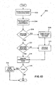
- FIG. 10 is a flowchart diagramming an exemplary method of operation 200 of the exemplary printing system 8.
- the connection edge 35 of the printed circuit board 30 is connected to the media cartridge interface 160 of the printing machine 150.
- the processing unit 168 of the printing machine 150 reads one or more parameters 46 (e.g., the media type number 46a, 46a' and/or the serial number 46b, 46b') that is encoded by circuit pattern 44a and/or circuit pattern 44b on the printed circuit board 30 (or 30').
- parameters 46 e.g., the media type number 46a, 46a' and/or the serial number 46b, 46b'
- a parameter is in a reset state if it has not been previously set or programmed by the manufacturer of the printed circuit board of the media cartridge. If a parameter, such as a serial number, is in the reset state, then in step 208 the parameter (e.g., the serial number) must be programmed into the printed circuit board by the printing machine. This may be accomplished with fuse programming via the automated programming mechanism 170 described above. Once the parameter has been programmed into the printed circuit board, the new parameter (e.g., the serial number) is added as an entry in the appropriate location of the look-up table 180 in step 210.
- step 212 a determination is made as to whether or not the printed circuit board's parameters, such as the printed circuit board's serial number, has already been stored or logged into the look-up table. If the parameters have not yet been entered into the look-up table, then they are added to appropriate entries in the look-up table in step 210 (described above).
- step 214 the look-up table entry corresponding to the printed circuit board's parameters is selected for printing with the respective media cartridge. The selected look-up table entry may then be updated as printing proceeds.
- step 216 the processing unit 168 determines if the printing mechanism 154 is printing. If the printing mechanism 154 is printing, the process goes to step 218, and the entry for the remaining media array 192 corresponding to the attached printed circuit board and the media cartridge is modified and updated by decrementing a counter corresponding to the amount of media that is being printed and used. After the printing has been completed and the look-up table has been updated with the modified remaining media amount (or if there was no printing to begin with), the method 200 ends.
- the printing system of the present invention has many advantages over the prior art printing systems.
- the printing system of the present invention uses media cartridges with printed circuit boards that are inexpensive to manufacture, especially when compared to memory chips and mechanical switches.
- these printed circuit boards are easy and inexpensive to program with fuse programming, but they are capable of storing relatively large parameter numbers without requiring a large amount of space and components.
- the printed circuit boards of the present invention are reliable and resistant to electrostatic damage, as well as wear and tear, and may be used with standard, off-the-shelf hardware (as opposed to the custom fittings and housings required for mechanical switches).
- the inexpensive, yet large parameter capacity of these printed circuit boards enables the printing system of the present invention to utilize a much more detailed, in-depth, and feature rich look-up table for customizing printing projects and better regulating replacements of media cartridges.
- the printing machine of the present invention is capable of recognizing a wide variety of different types of media cartridges, as well as recognizing a large number of different media cartridges of the same type (and recalling information about them).
Description
- This invention pertains to the field of printing systems. More specifically, this invention pertains to the field of media cartridges for printers, such as label roll printers.
- Label roll printers are utilized in order to create customized labels for home or office purposes. Thus, the growing demand for customized labels in recent years has increased the use of these printers. Typically, label roll printer systems have been comprised of a media cartridge and a printing machine. The media cartridge may contain a media source, such as a roll of labels, and some sort of a media support assembly. The printing machine is often comprised of a housing, a processing unit with an operating system, and a printing mechanism.
- There have been some enhancements made in the prior art on this standard printer design. Prior art designs of media cartridges have included memory chips with custom interfacing contacts, and an electronic connection to their printing machines. The memory chips contain data about the type of media source that is contained within their media cartridges, and this data is sent electronically to the corresponding printing machines. The printing systems of the prior art that use such memory chips, however, have several drawbacks. First, the cost of such memory chips is often very high, greatly increasing the price of their corresponding media cartridges. Also, memory chips are often susceptible to electrostatic discharge. Thus, other appliances near the printers that create electrostatic discharge, or common everyday static electricity, may permanently damage the memory chips and render them useless. In addition, the use of solder joints in many memory chips also makes them susceptible to failure due to faulty solder connections.
- Instead of memory chips, other prior art printer system designs have used features that activate mechanical switches on their media cartridges to encode the types of media sources that are used. These prior art media cartridges using mechanical switches are also plagued by a variety of problems. First, mechanical switches are often very expensive and require custom fittings and housings. Therefore, the use of mechanical switches may significantly increase the cost of the printing system, and make it less appealing to consumers. Second, as products age, their mechanical moving parts are often susceptible to failure due to wear and tear. Thus, the mechanical switches utilized with these media cartridges are likely to fail as time passes. Finally, prior art designs have only been able to utilize a few mechanical switches per media cartridge. Since the amount of data mechanical switches can encode is proportional to the number of switches present, these media cartridge designs can only encode a very limited amount of data. Therefore, the mechanical switches may only enable the printing machine to distinguish between a few media types.
- Another disadvantage common to most of the prior art printing systems is that their printing machines are unable to recognize individual media cartridges.
EP0927639 discloses a printing apparatus and printing method utilising a fuse pattern mounted on the side of the cartridge for information writing. In other words, although these prior art printing systems enable their printing machines to recognize a number of different types of media cartridges as explained above, most do not create an individual identification parameter, such as a serial number, for identifying each media cartridge regardless of its media type. - Accordingly, it is desirable to have a media cartridge (e.e., label roll) for printing systems (e.g., label roll printers) that overcomes the above deficiencies associated with the prior art.
The present invention is a printing system comprising of a media cartridge as defined inclaim 1 and a printing machine as defined inclaim 2. The media cartridge is preferably comprised of a media source and a printed circuit board having a plurality of conductive traces with fusible links that form a circuit pattern on first and second slides of the printed circuit board. The fusible links encode information about the media cartridge. The fusible links may encode a media type number that contains information about the type of media source used in the media cartridge. In addition, or alternatively, the fusible links may encode a serial number specific to the media cartridge that enables it to be individually identified by the printing machine. - The printing machine is preferably comprised of a housing, a processing unit and a printing mechanism connected to the housing, a media cartridge interface connecting the printing machine to the media cartridge, and a look-up table. The look-up table may be comprised of the media type number for each media cartridge that has been attached to the printing machine. In addition, or alternatively, the look-up table may be comprised of the individual serial numbers for each of these media cartridges. The look-up table may also keep track of the amount of media used within individual media cartridges. Also, the look-up table may keep track of user settings associated with an individual media cartridge.
- Embodiments of the invention will now be described, by way of example, with reference to the drawings, of which:
-
FIG. 1 is a perspective view of an exemplary embodiment of a printing system. -
FIG. 2 is an exploded view of an exemplary embodiment of a media cartridge for use in the printing system ofFIG. 1 . -
FIG. 3 is a side view of an exemplary embodiment of a printed circuit board not forming part of the invention for use in the media cartridge ofFIG. 2 . -
FIGS. 4a-4b are side views of an exemplary embodiment of a printed circuit board according to the invention for use in the media cartridge ofFIG. 2 . -
FIG. 5 is a side view of an exemplary embodiment of the details of the electrical interconnections of one possible circuit pattern. -
FIG. 6 is a side view of an exemplary embodiment of a fixed support plate for use in the media cartridge ofFIG. 2 . -
FIG. 7 is a block diagram overview of the operation of the printing system ofFIG. 1 . -
FIG. 8 is a top view of an exemplary embodiment of a media cartridge interface for use in the printing system ofFIG. 1 . -
FIG. 9 is a block diagram of an exemplary embodiment of a look-up table for use in the operation of the printing system ofFIG. 1 , as shown inFIG. 7 . -
FIG. 10 is a flow chart of an exemplary method of the printing system ofFIG. 1 . - Turning now to the drawings,
FIG. 1 shows anexemplary printing system 8 of the present invention. Theprinting system 8 preferably comprises amedia cartridge 10 that is inserted into ahousing 152 of aprinting machine 150. While a label roll is shown inFIG. 1 as the media source for themedia cartridge 10, it should be understood that any type of media source, including media sources other than label rolls (e.g., label sheets, photograph paper, etc.), may be used with the printing system of the present invention. Similarly, while a label roll printer is shown inFIG. 1 as theprinting machine 150, it should also be understood that any type of printing machine, including printing machines other than label roll printers (e.g., laser printers, photograph printers, etc.), may be used with the printing system of the present invention. -
FIG. 2 illustrates an exploded view of an exemplary embodiment of themedia cartridge 10. Themedia cartridge 10 comprises a printedcircuit board assembly 20, amedia support assembly 70, amedia source 130, and a pair offasteners 140. The printedcircuit board assembly 20 comprises aprinted circuit board 30 and a printedcircuit board cover 50. -
FIG. 3 shows an example of the printedcircuit board 30 in greater detail. The printedcircuit board 30 has afirst side 32, a second side 34 (seeFIG. 4 ), aconnection edge 35, and a pair offastener holes 42. Thefirst side 32 of the printedcircuit board 30 preferably has a plurality ofconductive traces 36a withfusible links 38a that are connected together to form acircuit pattern 44a. It should be understood that while twelveconductive traces 36a are shown in the printedcircuit board 30 ofFIG. 3 , more or lessconductive traces 36a may be used with the printed circuit board of the present invention, depending on consumer and/or manufacturing preferences. As shown inFIG. 3 , thefusible links 38a are also connected together by a commonconductive trace 39a, which in turn is also connected to a commonconductive trace 37a. Preferably, the plurality ofconductive traces 36a and the commonconductive trace 37a are all in communication with theconnection edge 35 of the printedcircuit board 30. - The
circuit pattern 44a (and its plurality ofconductive traces 36a andfusible links 38a) preferably has an encoding for one ormore parameters 46 associated with themedia cartridge 10 that includes the correspondingprinted circuit board 30, as shown inFIG. 3 . As discussed in more detail below, eachconductive trace 36a of thecircuit pattern 44a preferably represents a bit integer (i.e., 1 or 0), and the collection ofconductive traces 36a represent a binary number, which in turn may be translated into a numerical value for theparameter 46. As shown inFIG. 3 , the circuit pattern may include an encoding for asingle parameter 46, or alternatively, may include an encoding for two or more parameters, such as amedia type number 46a and aserial number 46b. In one example, themedia type number 46a may be encoded via eightconductive traces 36a (i.e., an eight bit number) of thecircuit pattern 44a, while theserial number 46b may be encoded via the remaining fourconductive traces 36a (i.e., a four bit number) of thecircuit pattern 44a. Of course, it should be understood that any combination ofconductive traces 36a may be used to represent these parameters, and the present invention should not be limited to the exemplary embodiment shown and described in the present application. In other words, themedia type number 46a and theserial number 46b may be comprised of any length bit number depending on the number of conductive traces used in the relative circuit pattern. - Preferably, the
media type number 46a (or 46a') is used to describe themedia source 130 used in themedia cartridge 10. In the present example, themedia source 130 is comprised of a roll of labels, so themedia type number 46a may encode a numerical value that identifies the type of label contained in themedia source 130. Similarly, theserial number 46b (or 46b') is preferably used to identify aparticular media cartridge 10 independent of its media type. In other words, such a serial number could make aspecific media cartridge 10 individually recognizable to theprinting machine 150. As a result, the printing machine is preferably capable of "remembering" a media cartridge and its characteristics (e.g., amount of labels remaining) even if it has been removed and later reinserted into the printing machine. - An exemplary embodiment of a printed circuit board 30' for use with the
media cartridge 10 of the present invention is shown inFIGS. 4a-4b . The printed circuit board 30' is identical to the printedcircuit board 30 described above and shown inFIG. 3 , except that both the first andsecond sides circuit patterns circuit patterns media type number 46a' and aserial number 46b'. Similarly, thesecond side 34 is preferably, but not necessarily, identical to thefirst side 32, except that itsparameter 46b' may be used for different purpose (i.e., a serial number) than theparameter 46a' (i.e., a media type number). For ease of reference, corresponding components of thesecond side 34 have been referenced with a "b" inFIG. 4b , instead of the "a" used inFIG. 4a . As an example, theconductive traces 36a and thefusible links 38a of thefirst side 32 of the printed circuit board have been referenced as the conductive traces 36b and thefusible links 38b for thesecond side 34 of the printed circuit board. It should be understood that the "a" and "b" components inFIGS. 4a and 4b are preferably identical (except for theparameters 46a' and 46b') unless otherwise stated to the contrary herein. - As a result of this exemplary embodiment, the
circuit pattern 44a of thefirst side 32 of the printed circuit board 30' may include an encoding for a twelve bitmedia type number 46a', and thecircuit pattern 44b of thesecond side 34 of the printed circuit board 30' may include an encoding for a twelve bitserial number 46b'. Once again, however, it should be understood that any combination of thecircuit patterns parameters 46a', 46b' (and/or any other parameters). -
FIG. 5 details the electrical interconnections of one possible circuit pattern for a printed circuit board of the present invention, regardless of which embodiment is employed for the printed circuit board. For exemplary purposes, however, only thecircuit pattern 44a ofFIG. 4a is shown inFIG. 5 and will described herein. It should be understood that the same electrical interconnections may be applied to thecircuit patterns FIGS. 3 and4b . - As shown in
FIG. 5 , thecircuit pattern 44a on thefirst side 32 may be formed by blowing open or breaking one or more of thefusible links 38a. The fusible links may be blown or broken in the following manner. First, a high voltage may be applied to one or more of theconductive traces 36a while grounding the commonconductive trace 37a. As a result, a large current may pass through one or more of thefusible links 38a connected to theconductive traces 36a that had the voltage applied to them. This large current then blows or breaks the one or morefusible links 38a it passes through, preventing any future current from passing through those one or morefusible links 38a. In other words, the one or morefusible links 38a through which the high current passed will now be part of an open circuit. It should be understood that thefusible links 38a may be blown or broken by the printed circuit board manufacturer or by the printing system that incorporates the printed circuit board, as discussed in more detail below. - In the exemplary embodiment shown in
FIG. 5 , the plurality ofconductive traces 36a are referenced as "Conductive trace A" through "Conductive trace L," and thefusible links 38a directly attached to Conductive trace A, Conductive trace D, and Conductive trace F have been blown or broken (represented by an "X"). As shown inFIG. 5 , each conductive trace (Conductive traces A-L) is labeled with a numerical value corresponding to its bit position within the binary number encoded in thecircuit pattern 44a. For example, Conductive trace A is assigned a numerical value of "1" (i.e., 20), Conductive trace B is assigned a numerical value of "2" (i.e., 21), Conductive trace C is assigned a numerical value of "4" (i.e., 22), and so on, with the number of possible combinations of encoded numerical values for the circuit pattern being directly proportional to the number ofconductive traces 36a (e.g., Conductive traces A-L). In other words, there are 2N possible combinations of encoded numerical values for the circuit pattern, where "N" is the number ofconductive traces 36a used to form the circuit pattern. In the exemplary embodiment shown inFIG. 5 , there would be "4096" (i.e., 212) possible combinations, since there are twelveconductive traces 36a in thecircuit pattern 44a. - Depending on which
fusible links 38a are blown or broken, thecircuit pattern 44a may encode a bit pattern (not shown). This bit pattern comprises a string of logical low and high values. In the exemplary embodiment shown inFIG. 5 , the blown or broken (i.e., open circuit)fusible links 38a correspond to logical high values (i.e., a binary "1"), and the non-blown or unbroken (i.e., closed circuit)fusible links 38a correspond to logical low values (i.e., a binary "0"). Thus, if Conductive traces A, D, and F are blown or broken, then the resulting binary number would be "000000101001," which also equates to a numerical value of "41" (i.e., 1+8+32 = 41). As explained above, this numerical value could be used to represent amedia type number 46a or aserial number 46b. - For more information on fusible links and fuse programming, one can refer to
U.S. Patent No. 4,879,587 . - It should be understood from the preceding discussion that in alternate embodiments, each
circuit pattern FIG. 4a-4b , in other alternate embodiments, only one side or a portion thereof may have a circuit pattern. Furthermore, in alternate embodiments, it is also possible that both sides or portions thereof may have a substantially similar circuit pattern. - Turning back to
FIG. 2 once again, the printedcircuit board cover 50 which houses the printedcircuit board 30 comprises afirst side 54, asecond side 56, and athird side 58 all preferably connected together and extending from abase 52. The printedcircuit board cover 50 also includes anopening 60 between the first andthird sides fastener connection area 62 with a pair of connection holes 63. In this exemplary embodiment, when assembled, thebase 52, thefirst side 54, thesecond side 56, and thethird side 58 partially enclose the printedcircuit board 30. Also, the connection holes 63 are preferably aligned with the fastener holes 42 of the printed circuit board 30 (or 30'). Therefore, when a pair offasteners 140 are passed through the connection holes 63 and the fastener holes 42, thefasteners 140 align and connect the printedcircuit board cover 50 to the printed circuit board 30 (or 30'). It should be understood that the design shown inFIG. 2 for the printedcircuit board cover 50 is merely exemplary, and alternate designs for covers that protect the printedcircuit board 30 may be utilized. It should also be understood that while the printedcircuit board cover 50 is preferably made from a polymer plastic such as polypropylene, polyurethane, or polyvinyl chloride, other suitable materials may be used for the printedcircuit board 50, depending on consumer and/or manufacturing preferences. - As shown in
FIG. 2 , themedia support assembly 70 is preferably (but not necessarily) comprised of amedia support 80, a fixedsupport plate 90, and anadjustable support plate 110. Themedia support 80 is comprised of anouter surface 82, afirst end 84, asecond end 86, and a malefastener connection area 88. In this exemplary embodiment, the malefastener connection area 88 is located at thefirst end 84 of themedia support 80, but may be located elsewhere in alternate embodiments, such as between thefirst end 84 and thesecond end 86. - As shown in
FIGS. 2 and6 , the fixedsupport plate 90 is preferably comprised of afirst side 92, asecond side 94, a femalefastener connection area 96, and a fingerplate 102 (seeFIG. 6 ). In this exemplary embodiment, thefingerplate 102 is preferably connected to thesecond side 94 of the fixedsupport plate 90. Thefingerplate 102 provides a convenient place to grasp the fixedsupport plate 90. The femalefastener connection area 96 is present on both thefirst side 92 and thesecond side 94 of the fixedsupport plate 90. As best shown inFIG. 2 , the femalefastener connection area 96 preferably contains a recessedportion 96a for receiving the malefastener connection area 88 of themedia support 80, and a pair ofsupport holes 96b aligned with the fastener holes 42 and the connection holes 63 for receiving thefasteners 140. Consequently, the malefastener connection area 88 may be mated with the recessedportion 96a of the femalefastener connection area 96 to connect themedia support 80 and the fixedsupport plate 90, and thefasteners 140 may be passed through the connection, fastener, and support holes 63, 42, 96b to connect the printercircuit board cover 50, the printedcircuit board 30, the fixedsupport plate 90, and themedia support 80 together. - The
adjustable support plate 110 is comprised of afirst side 112, asecond side 114, acentral bore 116, a central boreinner surface 118, afirst finger tab 120, and asecond finger tab 122. Thefirst finger tab 120 and thesecond finger tab 122 are preferably connected to thefirst side 112 of theadjustable support plate 110. Once again, like thefingerplate 102, thefirst finger tab 120 and thesecond finger tab 122 serve as a convenient place to grasp theadjustable support plate 110. Thecentral bore 116 passes through theadjustable support plate 110 from thefirst side 112 to thesecond side 114. The central boreinner surface 118 preferably has dimensions corresponding to theouter surface 82 of themedia support 80. Hence, in this exemplary embodiment, the central boreinner surface 118 can be removably mounted on theouter surface 82 of themedia support 80 near itssecond end 86 to removably connect theadjustable support plate 110 to the media support 80 (and thus the fixed support plate 90). - In this exemplary embodiment, the material used for all of the components in the
media support assembly 70 is preferably a polymer plastic, such as polypropylene, polyurethane, or polyvinyl chloride. Like the printedcircuit board cover 50, however, it should be understood that other suitable materials may be used for such components, depending on consumer and/or manufacturing preferences. - As shown in
FIG. 2 , themedia source 130 is preferably comprised of acentral bore 132, and a central boreinner surface 134. The central boreinner surface 134 preferably has dimensions larger than theouter surface 82 of themedia support 80. Hence, in this exemplary embodiment, the central boreinner surface 134 can be removably mounted on theouter surface 82 of themedia support 80. - In the exemplary embodiment shown in
FIG. 2 , themedia source 130 is a roll of labels, but different types of media may be used in alternate embodiments of the present invention. For example, in alternate embodiments, themedia source 130 may be a stack of papers or photographs, or a roll of another type of printable media. In such alternate embodiments, especially embodiments involving a stack of media, it should be understood that themedia support 80 may be more in the form of a tray for holding and supporting media, as opposed to the rod-like configuration shown inFIG. 2 . -
FIG. 2 also shows a pair offasteners 140, more specifically afirst fastener 142 and asecond fastener 144, which have been referred to above. In one exemplary embodiment, the fasteners may be metal screws. It should be understood, however, that other types of fasteners, such as nails, bolts, rivets, tabs, and snap-fit components, may be used with the media cartridge of the present invention, depending on consumer and/or manufacturing preferences. - Turning now to
FIG. 7 , a block diagram of anexemplary printing machine 150 is shown with electronic communications and connections indicated with arrows. Theexemplary printing machine 150 comprises aprocessing unit 168 that is connected to and in communication with aprinting mechanism 154, amedia cartridge interface 160, amemory unit 178, and auser interface 198. Theprocessing unit 168 is further comprised of anautomated programming mechanism 170, and thememory unit 178 is further comprised of a look-up table 180 and acounter 197. - The
printing mechanism 154 is the mechanical mechanism by which theprinting machine 150 prints. In one exemplary embodiment, the printing mechanism is a thermal printing mechanism. A thermal printing mechanism is generally comprised of a fixed linear array of heating elements designed to make direct contact with thermally sensitive media. It should be understood, however, that alternate embodiments are also possible, and theprinting mechanism 154 may, for example, be a dot matrix printing mechanism or a laser printing mechanism. For more information on thermal printing mechanisms and thermal printers, one can refer toU.S. Patent Nos. 3,965,330 and3,947,854 .U.S. Patent Nos. 3,965,330 and3,947,854 . - An exemplary embodiment of the
media cartridge interface 160 is shown inFIG. 8 . Themedia cartridge interface 160 is comprised of afirst end 162, asecond end 164, and awire band 166 connecting the first and second ends 162, 164. Thefirst end 162 of themedia cartridge interface 160 is designed to connect to theconnection edge 35 of the printedcircuit board 30 through theopening 60 in the printedcircuit board cover 50. When thefirst end 162 of themedia cartridge interface 160 is connected to theconnection edge 35 of the printedcircuit board 30, themedia cartridge interface 160 preferably contacts, and is capable of reading the encoding of, thecircuit pattern 44a and its plurality ofconductive traces 36a. - The
second end 164 of themedia cartridge interface 160 is designed to connect to theprocessing unit 168 on theprinting machine 160. Therefore, themedia cartridge interface 160 connects the printedcircuit board 30 to theprinting machine 150. While awire band 166 is shown in the exemplary embodiment ofFIG. 8 , however, it should be understood that the wire band is not necessary, and thesecond end 164 of the media cartridge interface may be mounted directly to, and formed integral with, the housing of the printing machine. - In one exemplary embodiment, the
media cartridge interface 160 is a simple off-the-shelf card edge connector, but any device known to form an interface with printed circuit boards may be used. For more information on this subject, one can refer toU.S. Patents Nos. 6,254,435 and6,174,184 , which pertain to card edge connectors.U.S. Patents Nos. 6,254,435 and6,174,184 . - In the exemplary embodiment of the
printing machine 150 shown inFIG. 7 , theprocessing unit 168 of theprinting machine 150 is a microprocessor running a proprietary operating system. Generally, computational processes that take place within theprinting machine 150 take place in theprocessing unit 168. Furthermore, theprocessing unit 168 connects to and controls theprinting mechanism 154, themedia cartridge interface 160, thememory unit 178, and theuser interface 198. In this exemplary embodiment, theparameters 46 of the printedcircuit board 30, such as themedia type number 46a and/or theserial number 46b, are received at theprinting machine 150 by theprocessing unit 168 via themedia cartridge interface 160. It should be understood that the preceding description of the processing unit is only exemplary, and one of ordinary skill in the art would be able to contemplate other alternate embodiments without departing from the scope and spirit of the present invention. - The
processing unit 168 is further comprised of anautomated programming mechanism 170, which may be used to fuse program the printedcircuit board 30. In this exemplary embodiment, theautomated programming mechanism 170 is a device that sends a high current across themedia cartridge interface 160 through one of more of theconductive traces 36a and/or theconductive traces 36b in order to blow or break one or more of thefusible links 38a and/orfusible links 38b, respectively.Fusible links 38a and/orfusible links 38b are sized to require a small amount of current to melt or vaporize the link. The method of operation of such a device as theautomated programming mechanism 170 has been explained earlier when discussing the printedcircuit board 30. For more information on fusible links and fusible link programming devices such as theautomated programming mechanism 170, one can refer toU.S. Patent No. 4,879,587 , which has already been incorporated by reference, andU.S. Patent No. 5,025,300 . -
FIG. 7 also shows theexemplary memory unit 178. In this exemplary embodiment, thememory unit 178 is preferably a non-volatile memory device such that memory values will not be lost when the printing machine is powered off. Of course, other memory devices known in the art may also be used with the memory unit of the present invention. Preferably, thememory unit 178 is electronically connected to theprocessing unit 168, and is also physically contained in thehousing 152 of theprinting machine 150. - As shown in
FIG. 7 , a look-up table 180 may be stored in thememory unit 178. Preferably, but not necessarily, the look-up table 180 is a first-in-first-out (FIFO) storage table that is comprised of a set ofrow entries 182, as shown inFIG. 9 . In one exemplary embodiment, there may anywhere up to thirtyrow entries 182 in the look-up table 180, but more or less row entries may be used depending on the memory size and consumer and/or manufacturing preferences. As shown inFIG. 9 , each row entry in the set ofrow entries 182 is comprised of one column entry from each of the following column arrays: anindex array 184, a mediatype number array 186, aserial number array 188, a startingmedia amount array 190, and a remainingmedia amount array 192. To simplify the analysis of the look-up table 180, one can examine asample row entry 194 in light of each exemplary column array in closer detail. - The
index array 184 keeps track of the number of entries in the look-up table 180. Theprocessing unit 168 is the unit that updates and modifies theindex array 184. Forsample row entry 194, the corresponding value in theindex array 184 is "6." Therefore, in this exemplary embodiment, thesample row entry 194 is the sixth row entry in the set ofrow entries 182. - Each entry in the media
type number array 186 identifies the type ofmedia source 130 present in amedia cartridge 10 that has been loaded into theprinting machine 150. Thus, each entry in this array is amedia type number 46a (or 46a') that was sent from the printedcircuit board 30 to the look-up table 180 via themedia cartridge interface 160 and theprocessing unit 168.FIG. 9 shows that themedia type number 46a corresponding to thesample row entry 194 is "10." This value of "10" may be used to indicate that themedia source 130 of themedia cartridge 10 inserted into the printing machine is a roll of 2 inch by 4 inch shipping labels. Theprocessing unit 168 can also utilize themedia type number 46a to customize the printing process for the type of media source in the media cartridge. - Each element in the
serial number array 188 individually identifies aparticular media cartridge 10 to which theprinting machine 150 has been connected. Each element in theserial number array 188 is aserial number 46b (or 46b') sent from the printedcircuit board 30 to the look-up table 180 via themedia cartridge interface 160 and theprocessing unit 168.FIG. 9 shows that theserial number 46a corresponding to thesample row entry 194 is "3424." This value of "3424" may be used by the printing machine to recall information, such as how much media is left, about a media cartridge that was removed and later reinserted. - The starting
media amount array 190 stores the value of the amount of media that is present in an unused,new media cartridge 10. In this exemplary embodiment, this value is already stored within thememory unit 168. However, it is possible in alternate embodiments that this value is obtained in another manner. For example, an entry in the startingmedia amount array 190 may be obtained from the printedcircuit board 30 as aparameter 46a or aparameter 46b. InFIG. 9 , the exemplary value in the startingmedia amount array 190 corresponding to thesample row entry 194 is "100." Thus, a media source of the label roll type "10" may initially include one hundred labels on its roll. - Each entry in the remaining
media amount array 192 tracks the amount of media remaining in aspecific media cartridge 10. Initially, each element in the remainingmedia amount array 192 is given the value of the corresponding entry in the startingmedia amount array 190. Then, as media is printed and used from themedia cartridge 10, the value of the entry in the remainingmedia amount array 192 that corresponds to themedia cartridge 10 is decremented. In the exemplary embodiment of the printing machine shown inFIG. 7 , this decrementation is achieved by acounter 197. The value of the entry in the remainingmedia amount array 192 is passed to thecounter 197, where it is decremented as media is used, and then passed back to the remainingmedia amount array 192. As an illustration of this process,FIG. 9 shows the value in the remainingmedia amount array 192 corresponding to thesample row entry 194 is "15." Hence, this means that eighty-five pieces of media have been printed frommedia cartridge 10 with the serial number of "3424," since there were originally one-hundred and now there are only fifteen left. If nine more pieces of media are printed from the "3424" media cartridge, thecounter 197 would receive the value "15" from the remainingmedia amount array 192, decrement it by "9," and store back the value "6" in the remainingmedia amount array 192 entry corresponding to the "3424" media cartridge. Thus, the remainingmedia amount array 192 holds the correct value of the amount of media remaining onmedia cartridge 10. It should be understood that the decrementation explained above may be achieved in a variety of ways, such as by having each entry in the remainingmedia amount array 192 be a counter itself, without departing from the scope and spirit of the present invention. - Returning to
FIG. 7 , as mentioned above, the printing machine may also include auser interface 198 connected to and in communication with theprocessing unit 168. In this exemplary embodiment, theuser interface 198 is preferably a display, such as a Liquid Crystal Display (LCD), that shows to the user of the printing machine the amount of media remaining in the media cartridge (i.e., the entries from the remainingmedia amount array 192 of the look-up table 180), themedia type number 46a, and/or theserial number 46b, as well as possible error and warning messages. Values for these amounts and numbers may be acquired from the look-up table 180 via theprocessing unit 168. In alternate embodiments, many other embellishments may be added to theuser interface 198, such as creating a user input module that would enable the user to make custom changes to the printing procedure. Thus, it should be understood that a variety of different user interfaces may be used in alternate embodiments of the present invention. - Having examined the structure and connectivity of the elements of the exemplary printing system, an exemplary method of operation of the printing system will now be described.
FIG. 10 is a flowchart diagramming an exemplary method ofoperation 200 of theexemplary printing system 8. In the first step,step 202, theconnection edge 35 of the printedcircuit board 30 is connected to themedia cartridge interface 160 of theprinting machine 150. Next, instep 204, theprocessing unit 168 of theprinting machine 150 reads one or more parameters 46 (e.g., themedia type number serial number circuit pattern 44a and/orcircuit pattern 44b on the printed circuit board 30 (or 30'). - In
step 206, a determination is preferably made by theprocessing unit 168 as to whether a parameter, such as the serial number, is in a reset state. A parameter is in a reset state if it has not been previously set or programmed by the manufacturer of the printed circuit board of the media cartridge. If a parameter, such as a serial number, is in the reset state, then instep 208 the parameter (e.g., the serial number) must be programmed into the printed circuit board by the printing machine. This may be accomplished with fuse programming via theautomated programming mechanism 170 described above. Once the parameter has been programmed into the printed circuit board, the new parameter (e.g., the serial number) is added as an entry in the appropriate location of the look-up table 180 instep 210. - Returning to the decision of
step 206, if there are no parameters in the reset state (i.e., all of the parameters were previously set or programmed by the printed circuit board manufacturer), then themethod 200 continues withstep 212. As shown inFIG. 10 , instep 212, a determination is made as to whether or not the printed circuit board's parameters, such as the printed circuit board's serial number, has already been stored or logged into the look-up table. If the parameters have not yet been entered into the look-up table, then they are added to appropriate entries in the look-up table in step 210 (described above). - As shown in
FIG. 10 , if the printed circuit board's parameters have already been entered into the look-up table, or they have been added to the look-up table pursuant to step 210, then themethod 200 continues withstep 214. Instep 214, the look-up table entry corresponding to the printed circuit board's parameters is selected for printing with the respective media cartridge. The selected look-up table entry may then be updated as printing proceeds. - Finally, in
step 216, theprocessing unit 168 determines if theprinting mechanism 154 is printing. If theprinting mechanism 154 is printing, the process goes to step 218, and the entry for the remainingmedia array 192 corresponding to the attached printed circuit board and the media cartridge is modified and updated by decrementing a counter corresponding to the amount of media that is being printed and used. After the printing has been completed and the look-up table has been updated with the modified remaining media amount (or if there was no printing to begin with), themethod 200 ends. - The printing system of the present invention has many advantages over the prior art printing systems. For example, the printing system of the present invention uses media cartridges with printed circuit boards that are inexpensive to manufacture, especially when compared to memory chips and mechanical switches. In addition, not only are these printed circuit boards easy and inexpensive to program with fuse programming, but they are capable of storing relatively large parameter numbers without requiring a large amount of space and components. Moreover, the printed circuit boards of the present invention are reliable and resistant to electrostatic damage, as well as wear and tear, and may be used with standard, off-the-shelf hardware (as opposed to the custom fittings and housings required for mechanical switches). Indeed, the inexpensive, yet large parameter capacity of these printed circuit boards enables the printing system of the present invention to utilize a much more detailed, in-depth, and feature rich look-up table for customizing printing projects and better regulating replacements of media cartridges. Furthermore, the printing machine of the present invention is capable of recognizing a wide variety of different types of media cartridges, as well as recognizing a large number of different media cartridges of the same type (and recalling information about them).
- It should be understood that a wide variety of changes and modifications may be made to the embodiments of the printing system described above. For instance, the normal functions and/or determinations handled by the processing unit of the printing machine may be distributed to other intelligent components of the printing machine and off-loaded from the main processor. In addition, certain components, functions, and operations of the printing system of the present invention may be accomplished with hardware, software, and/or a combination of the two.
Claims (13)
- A media cartridge (10) for use with a printing machine (150), the media cartridge comprising
a printed circuit board (30) for connecting electronically to a printing machine, characterised by
the printed circuit board having a plurality of conductive traces (36a) with fusible links (38a) connected together in a circuit pattern on first and second sides of the printed circuit board. - A printing machine including a media cartridge as claimed in claim 1, the printing machine comprising:a housing (152);a printing mechanism (154) connected to the housing;a processing unit (168) connected to the housing; anda media cartridge interface (160) characterised bya first end (162) connected to the processing unit and a second end (164) configured for connecting electronically to a printed circuit board of said media cartridge;wherein the printed circuit board has a plurality of conductive traces with fusible links connected together in a circuit pattern on first and second sides of the printed circuit board.
- A printing machine as claimed in claim 2, the printing machine further comprising:a look-up table (180) for storing at least one parameter associated with the media cartridge, the at least one parameter associated with the media cartridge being sent electronically from the printed circuit board of the media cartridge to the look-up table of the printing machine across the media cartridge interface,
- The printing machine of claim 2 or 3, wherein the printing machine further comprises an automated programming mechanism (170) in communication with the printed circuit board, the automated programming mechanism producing an electrical current that passes through and breaks at least one of the fusible links on the printed circuit board to create a further circuit pattern on at least one side of the printed circuit board.
- The media cartridge of claim 1 or the printing machine of any of claims 2 to 4, wherein the circuit pattern on the printed circuit board comprises an encoding of at least one parameter associated with the media cartridge.
- The media cartridge or the printing machine of claim 3 or claim 5, wherein the at least one parameter associated with the media cartridge comprises a serial number (188) identifying the media cartridge.
- The media cartridge of claim 1, wherein the media cartridge further comprises a media support (80) connected to the printed circuit board.
- The media cartridge of claim 7, wherein the media cartridge further comprises a media source (130) mounted on the media support.
- The media cartridge of claim 1 or the printing machine of claim 3, wherein the circuit pattern or at least one parameter associated with the media cartridge comprises a media type number (186) identifying the type of the media source for the media cartridge.
- The media cartridge or printing machine of claim 9, wherein the circuit pattern on at least one side of the printed circuit board comprises an encoding of a serial number identifying the media cartridge.
- The media cartridge of claim 8, wherein the media source further comprises a roll of labels.
- The printing machine of claims 2 or 3, wherein the printing mechanism comprises a thermal printing mechanism.
- A printing system comprising:a printing machine as claimed in claim 2 wherein the media cartridge interface second end is connected electronically to the media cartridge.
Applications Claiming Priority (2)
| Application Number | Priority Date | Filing Date | Title |
|---|---|---|---|
| US957987 | 2001-09-21 | ||
| US09/957,987 US6830391B2 (en) | 2001-09-21 | 2001-09-21 | Media cartridge with printed circuit board for use in a printing system |
Publications (3)
| Publication Number | Publication Date |
|---|---|
| EP1297965A2 EP1297965A2 (en) | 2003-04-02 |
| EP1297965A3 EP1297965A3 (en) | 2003-07-02 |
| EP1297965B1 true EP1297965B1 (en) | 2008-08-13 |
Family
ID=25500452
Family Applications (1)
| Application Number | Title | Priority Date | Filing Date |
|---|---|---|---|
| EP02256285A Expired - Fee Related EP1297965B1 (en) | 2001-09-21 | 2002-09-11 | Media cartridge with printed circuit board for use in a printing system |
Country Status (5)
| Country | Link |
|---|---|
| US (2) | US6830391B2 (en) |
| EP (1) | EP1297965B1 (en) |
| JP (1) | JP2003182131A (en) |
| CN (1) | CN1301861C (en) |
| DE (1) | DE60228181D1 (en) |
Families Citing this family (16)
| Publication number | Priority date | Publication date | Assignee | Title |
|---|---|---|---|---|
| US7663780B2 (en) * | 1999-06-30 | 2010-02-16 | Silverbrook Research Pty Ltd | Cartridge with identifiers |
| GB0230200D0 (en) * | 2002-12-24 | 2003-02-05 | Esselte Nv | Validation of consumables |
| US7111806B2 (en) * | 2004-08-05 | 2006-09-26 | Esselte | Spool for supply of image receiving medium |
| WO2006021021A1 (en) * | 2004-08-26 | 2006-03-02 | Silverbrook Research Pty Ltd | Cartridge with identifiers |
| WO2006049614A1 (en) * | 2004-10-29 | 2006-05-11 | Simplexgrinnell Lp | Method and apparatus for assigning addresses to alarm system devices |
| EP2769850A3 (en) | 2004-11-30 | 2016-04-13 | Panduit Corporation | Market-based labeling systems and method |
| US20080080918A1 (en) * | 2005-03-17 | 2008-04-03 | Panduit Corp. | Hand-held thermal transfer printer for labeling |
| US7703998B2 (en) * | 2006-11-30 | 2010-04-27 | Avery Dennison Retail Information Services Llc | Mounting assembly for printer |
| DE102007036836A1 (en) * | 2007-08-02 | 2009-02-05 | Siemens Ag | Coding device for storage of configuration data of electric device, has conductive strip fuses provided on printed circuit board, where fuses are separated depending upon contents of configuration data |
| KR101198771B1 (en) * | 2008-01-09 | 2012-11-12 | 삼성전자주식회사 | Image forming apparatus and method the same |
| GB2459531B (en) * | 2008-04-29 | 2010-10-13 | Dymo Nv | Label printer |
| US8599424B2 (en) * | 2008-09-04 | 2013-12-03 | Fb Sistemas S.A. | Printer cartridge microchip |
| JP4871946B2 (en) * | 2008-10-31 | 2012-02-08 | 東芝テック株式会社 | Printer |
| BR112012017466A2 (en) * | 2010-01-19 | 2017-09-26 | Printronix Inc | "tape cartridge, and method of operating a printer system" |
| US11123999B2 (en) | 2018-09-03 | 2021-09-21 | Sanford, L.P. | Cassettes and label printers therefor |
| JP7439596B2 (en) * | 2020-03-19 | 2024-02-28 | セイコーエプソン株式会社 | board cartridge |
Family Cites Families (51)
| Publication number | Priority date | Publication date | Assignee | Title |
|---|---|---|---|---|
| US376796A (en) * | 1888-01-24 | Holdback | ||
| US361342A (en) * | 1887-04-19 | Horse-collar | ||
| US373791A (en) * | 1887-11-22 | Tidjj | ||
| US3134254A (en) | 1961-01-24 | 1964-05-26 | Joseph D Richard | Secure locking system |
| US3392558A (en) | 1965-10-23 | 1968-07-16 | Robert A. Hedin | Binary coded electronic lock and key |
| DE2256688B2 (en) | 1972-11-18 | 1976-05-06 | Robert Bosch Gmbh, 7000 Stuttgart | PROCESS FOR SEPARATING CONDUCTOR TRACKS ON INTEGRATED CIRCUITS |
| US4437229A (en) | 1979-12-06 | 1984-03-20 | Western Electric Company, Inc. | Methods of marking and electrically identifying an article |
| JPS624046A (en) | 1985-06-26 | 1987-01-10 | 株式会社 サト− | Unit type thermal lebel printer |
| JP2551410B2 (en) | 1986-06-10 | 1996-11-06 | 株式会社 サト− | Electronic handler bella |
| US5051009A (en) | 1986-07-15 | 1991-09-24 | Monarch Marking Systems, Inc. | Printhead mount & cassette lock in a thermal printer |
| US5024541A (en) | 1987-04-17 | 1991-06-18 | Casio Computer Co., Ltd. | Manually operable sweeping-type printing apparatus |
| DE3718013C1 (en) * | 1987-05-27 | 1988-11-10 | Triumph Adler Ag | Ribbon cassette for electronically controlled typewriters or similar office machines |
| JPS63298869A (en) * | 1987-05-29 | 1988-12-06 | Matsushita Electric Ind Co Ltd | Recording and reproducing device |
| US5056940A (en) | 1988-02-01 | 1991-10-15 | Kroy Inc. | Thermal printing device and tape supply cartridge therefor |
| US5078523A (en) | 1988-03-04 | 1992-01-07 | Varitronic Systems, Inc. | Tape cassette with identifying circuit element for printing machine |
| US5015324A (en) | 1988-06-22 | 1991-05-14 | Monarch Marking Systems, Inc. | Hand-held labeler |
| JPH063839B2 (en) * | 1988-12-16 | 1994-01-12 | 株式会社東芝 | Semiconductor integrated circuit device |
| JPH068194A (en) * | 1991-08-02 | 1994-01-18 | Brother Ind Ltd | Cutter driving device |
| JPH0596804A (en) | 1991-10-14 | 1993-04-20 | Hitachi Ltd | Ink sheet and cassette thereof |
| US5237487A (en) | 1992-03-02 | 1993-08-17 | Ncr Corporation | Transaction terminal having base module and portable module |
| US5363134A (en) * | 1992-05-20 | 1994-11-08 | Hewlett-Packard Corporation | Integrated circuit printhead for an ink jet printer including an integrated identification circuit |
| US5504507A (en) | 1992-10-08 | 1996-04-02 | Xerox Corporation | Electronically readable performance data on a thermal ink jet printhead chip |
| US5318370A (en) | 1992-11-17 | 1994-06-07 | Varitronic Systems, Inc. | Cartridge with data memory system and method regarding same |
| USD361342S (en) | 1993-08-19 | 1995-08-15 | Brother Kogyo Kabushiki Kaisha | Tape cartridge for tape printer |
| US5471163A (en) * | 1993-11-16 | 1995-11-28 | Hewlett-Packard Company | Tab circuit fusible links for disconnection or encoding information |
| US5358798A (en) | 1993-12-06 | 1994-10-25 | Motorola, Inc. | Battery assembly having a thermal fuse |
| US5411339A (en) | 1993-12-09 | 1995-05-02 | Kroy, Inc. | Portable printer and cartridge therefor |
| US5435657A (en) | 1993-12-28 | 1995-07-25 | Smith Corona Corporation | Label printer and tape and ink ribbon cartridge for use therein |
| US5421745A (en) | 1994-01-03 | 1995-06-06 | Motorola, Inc. | Contact array |
| US6042280A (en) | 1995-05-25 | 2000-03-28 | Brother Kogyo Kabushiki Kaisha | Tape label printing device |
| JP3111445B2 (en) | 1995-03-29 | 2000-11-20 | ブラザー工業株式会社 | Tape-shaped label making device |
| JP2976823B2 (en) | 1994-09-28 | 1999-11-10 | ブラザー工業株式会社 | Cassette case and tape case for making printing tape |
| US5472804A (en) | 1994-12-01 | 1995-12-05 | Motorola, Inc. | Battery device with integrated circuit substrate packaging |
| US5699091A (en) * | 1994-12-22 | 1997-12-16 | Hewlett-Packard Company | Replaceable part with integral memory for usage, calibration and other data |
| JP3113532B2 (en) | 1994-12-28 | 2000-12-04 | アルプス電気株式会社 | Tape cassette |
| US6132120A (en) | 1995-03-29 | 2000-10-17 | Brother Kogyo Kabushiki Kaisha | Tape-shaped label printing device |
| USD373791S (en) | 1995-05-16 | 1996-09-17 | Sega Enterprises, Ltd. | Cartridge for video printer |
| US5740066A (en) | 1995-07-03 | 1998-04-14 | Motorola, Inc. | Electrical circuit board and circuit board assembly |
| GB9513532D0 (en) | 1995-07-04 | 1995-09-06 | Esselte Dymo Nv | Printing device construction |
| US5587250A (en) | 1995-09-27 | 1996-12-24 | Motorola, Inc. | Hybrid energy storage system |
| USD376796S (en) | 1995-12-28 | 1996-12-24 | Casio Computer Co., Ltd. | Ribbon cassette for a video game machine with seal printer |
| US5823689A (en) | 1996-03-19 | 1998-10-20 | Varitronic Systems, Inc. | Computer system with bi-directional communication and method |
| US5670266A (en) | 1996-10-28 | 1997-09-23 | Motorola, Inc. | Hybrid energy storage system |
| US5800937A (en) | 1997-05-02 | 1998-09-01 | Motorola, Inc. | Current interrupt device for secondary batteries |
| JP3487576B2 (en) | 1997-12-29 | 2004-01-19 | キヤノン株式会社 | Ink jet recording device |
| US5951177A (en) | 1998-03-02 | 1999-09-14 | Brady Worldwide | Method and apparatus for maintaining ribbon tension |
| US5918989A (en) * | 1998-03-02 | 1999-07-06 | Brady Worldwide, Inc. | Hand held label printer spool |
| US5896080A (en) | 1998-04-10 | 1999-04-20 | Kun-Ming Tsai | Thermal fuse for fixing on a circuit board |
| US6161915A (en) * | 1998-06-19 | 2000-12-19 | Lexmark International, Inc | Identification of thermal inkjet printer cartridges |
| WO2000032406A1 (en) | 1998-12-03 | 2000-06-08 | Sony Corporation | Thermal transfer printer system |
| US6325483B1 (en) * | 2000-07-19 | 2001-12-04 | Hewlett-Packard Company | Techniques for increasing ink-jet pen identification information in an interconnect limited environment |
-
2001
- 2001-09-21 US US09/957,987 patent/US6830391B2/en not_active Expired - Fee Related
-
2002
- 2002-09-11 DE DE60228181T patent/DE60228181D1/en not_active Expired - Fee Related
- 2002-09-11 EP EP02256285A patent/EP1297965B1/en not_active Expired - Fee Related
- 2002-09-19 JP JP2002272810A patent/JP2003182131A/en active Pending
- 2002-09-20 CN CNB021432163A patent/CN1301861C/en not_active Expired - Fee Related
-
2004
- 2004-12-02 US US11/002,397 patent/US7037014B2/en not_active Expired - Fee Related
Also Published As
| Publication number | Publication date |
|---|---|
| DE60228181D1 (en) | 2008-09-25 |
| CN1420021A (en) | 2003-05-28 |
| US20050100383A1 (en) | 2005-05-12 |
| US20030059246A1 (en) | 2003-03-27 |
| US7037014B2 (en) | 2006-05-02 |
| EP1297965A2 (en) | 2003-04-02 |
| CN1301861C (en) | 2007-02-28 |
| EP1297965A3 (en) | 2003-07-02 |
| US6830391B2 (en) | 2004-12-14 |
| JP2003182131A (en) | 2003-07-03 |
Similar Documents
| Publication | Publication Date | Title |
|---|---|---|
| EP1297965B1 (en) | Media cartridge with printed circuit board for use in a printing system | |
| EP0940254B1 (en) | Electrical storage device for a replaceable printing component | |
| JP3811496B2 (en) | State recognition tag | |
| EP0265227B1 (en) | An ic memory cartridge and a method for providing external ic memory cartridges to an electronic device | |
| US5075724A (en) | System for recognizing interchangeable articles | |
| CN101118825B (en) | Fuse system with serviceable connections | |
| EP1622066B1 (en) | Tag, system and method for managing merchandise distribution | |
| CA2635877A1 (en) | Universal smart chip cartridge for multiple printing apparatus | |
| US8397997B2 (en) | Removable media spindle and antenna assembly for printer | |
| US5483889A (en) | Automatic media size detector | |
| US8874402B2 (en) | Physical memory handling for handheld field maintenance tools | |
| US6436516B1 (en) | Information seal | |
| US6083771A (en) | Method and system for manufacturing theft-deterrent computer components | |
| EP0793169A1 (en) | Identification interface | |
| US6601219B2 (en) | Electronic apparatus and manufacturing method for an electronic apparatus | |
| EP0277940A1 (en) | Card or pass in plastic material incorporating an integrated memory circuit. | |
| JP4589673B2 (en) | RFID printer and control method | |
| JP4460469B2 (en) | Parts confirmation method | |
| CN108528073A (en) | Tape printing apparatus | |
| CN209938054U (en) | Label printer with RFID module | |
| JPH0250849A (en) | Apparatus for detecting inferiority of heating circuit of thermal head | |
| CN115275472A (en) | Battery box and electronic price display comprising same | |
| JP2571001B2 (en) | IC package with writing status display mechanism | |
| US8736648B1 (en) | Vinyl tape cartridge life validation | |
| JPH02200474A (en) | Printer |
Legal Events
| Date | Code | Title | Description |
|---|---|---|---|
| PUAI | Public reference made under article 153(3) epc to a published international application that has entered the european phase |
Free format text: ORIGINAL CODE: 0009012 |
|
| AK | Designated contracting states |
Kind code of ref document: A2 Designated state(s): AT BE BG CH CY CZ DE DK EE ES FI FR GB GR IE IT LI LU MC NL PT SE SK TR |
|
| AX | Request for extension of the european patent |
Extension state: AL LT LV MK RO SI |
|
| PUAL | Search report despatched |
Free format text: ORIGINAL CODE: 0009013 |
|
| AK | Designated contracting states |
Designated state(s): AT BE BG CH CY CZ DE DK EE ES FI FR GB GR IE IT LI LU MC NL PT SE SK TR |
|
| AX | Request for extension of the european patent |
Extension state: AL LT LV MK RO SI |
|
| 17P | Request for examination filed |
Effective date: 20031218 |
|
| AKX | Designation fees paid |
Designated state(s): DE FR GB IT |
|
| 17Q | First examination report despatched |
Effective date: 20050718 |
|
| GRAP | Despatch of communication of intention to grant a patent |
Free format text: ORIGINAL CODE: EPIDOSNIGR1 |
|
| GRAS | Grant fee paid |
Free format text: ORIGINAL CODE: EPIDOSNIGR3 |
|
| GRAA | (expected) grant |
Free format text: ORIGINAL CODE: 0009210 |
|
| AK | Designated contracting states |
Kind code of ref document: B1 Designated state(s): DE FR GB IT |
|
| REG | Reference to a national code |
Ref country code: GB Ref legal event code: FG4D |
|
| REF | Corresponds to: |
Ref document number: 60228181 Country of ref document: DE Date of ref document: 20080925 Kind code of ref document: P |
|
| PGFP | Annual fee paid to national office [announced via postgrant information from national office to epo] |
Ref country code: DE Payment date: 20081002 Year of fee payment: 7 |
|
| PGFP | Annual fee paid to national office [announced via postgrant information from national office to epo] |
Ref country code: FR Payment date: 20081014 Year of fee payment: 7 |
|
| PLBE | No opposition filed within time limit |
Free format text: ORIGINAL CODE: 0009261 |
|
| STAA | Information on the status of an ep patent application or granted ep patent |
Free format text: STATUS: NO OPPOSITION FILED WITHIN TIME LIMIT |
|
| PGFP | Annual fee paid to national office [announced via postgrant information from national office to epo] |
Ref country code: GB Payment date: 20081001 Year of fee payment: 7 |
|
| 26N | No opposition filed |
Effective date: 20090514 |
|
| PG25 | Lapsed in a contracting state [announced via postgrant information from national office to epo] |
Ref country code: IT Free format text: LAPSE BECAUSE OF FAILURE TO SUBMIT A TRANSLATION OF THE DESCRIPTION OR TO PAY THE FEE WITHIN THE PRESCRIBED TIME-LIMIT Effective date: 20080813 |
|
| REG | Reference to a national code |
Ref country code: FR Ref legal event code: ST Effective date: 20090731 |
|
| REG | Reference to a national code |
Ref country code: FR Ref legal event code: RN |
|
| REG | Reference to a national code |
Ref country code: FR Ref legal event code: FC |
|
| GBPC | Gb: european patent ceased through non-payment of renewal fee |
Effective date: 20090911 |
|
| PG25 | Lapsed in a contracting state [announced via postgrant information from national office to epo] |
Ref country code: DE Free format text: LAPSE BECAUSE OF NON-PAYMENT OF DUE FEES Effective date: 20100401 |
|
| PG25 | Lapsed in a contracting state [announced via postgrant information from national office to epo] |
Ref country code: GB Free format text: LAPSE BECAUSE OF NON-PAYMENT OF DUE FEES Effective date: 20090911 |
|
| PG25 | Lapsed in a contracting state [announced via postgrant information from national office to epo] |
Ref country code: FR Free format text: LAPSE BECAUSE OF NON-PAYMENT OF DUE FEES Effective date: 20081013 |
|
| REG | Reference to a national code |
Ref country code: FR Ref legal event code: ST Effective date: 20121019 |
|
| PGRI | Patent reinstated in contracting state [announced from national office to epo] |
Ref country code: FR Effective date: 20121004 |
|
| PGRI | Patent reinstated in contracting state [announced from national office to epo] |
Ref country code: FR Effective date: 20121004 |