EP1297787A1 - Intracardiac suture device - Google Patents
Intracardiac suture device Download PDFInfo
- Publication number
- EP1297787A1 EP1297787A1 EP02021781A EP02021781A EP1297787A1 EP 1297787 A1 EP1297787 A1 EP 1297787A1 EP 02021781 A EP02021781 A EP 02021781A EP 02021781 A EP02021781 A EP 02021781A EP 1297787 A1 EP1297787 A1 EP 1297787A1
- Authority
- EP
- European Patent Office
- Prior art keywords
- shaft
- suture needle
- suture
- holding means
- hollow member
- Prior art date
- Legal status (The legal status is an assumption and is not a legal conclusion. Google has not performed a legal analysis and makes no representation as to the accuracy of the status listed.)
- Granted
Links
Images


Classifications
-
- A—HUMAN NECESSITIES
- A61—MEDICAL OR VETERINARY SCIENCE; HYGIENE
- A61B—DIAGNOSIS; SURGERY; IDENTIFICATION
- A61B17/00—Surgical instruments, devices or methods, e.g. tourniquets
- A61B17/04—Surgical instruments, devices or methods, e.g. tourniquets for suturing wounds; Holders or packages for needles or suture materials
- A61B17/0469—Suturing instruments for use in minimally invasive surgery, e.g. endoscopic surgery
-
- A—HUMAN NECESSITIES
- A61—MEDICAL OR VETERINARY SCIENCE; HYGIENE
- A61B—DIAGNOSIS; SURGERY; IDENTIFICATION
- A61B17/00—Surgical instruments, devices or methods, e.g. tourniquets
- A61B17/00234—Surgical instruments, devices or methods, e.g. tourniquets for minimally invasive surgery
- A61B2017/00238—Type of minimally invasive operation
- A61B2017/00243—Type of minimally invasive operation cardiac
-
- A—HUMAN NECESSITIES
- A61—MEDICAL OR VETERINARY SCIENCE; HYGIENE
- A61B—DIAGNOSIS; SURGERY; IDENTIFICATION
- A61B90/00—Instruments, implements or accessories specially adapted for surgery or diagnosis and not covered by any of the groups A61B1/00 - A61B50/00, e.g. for luxation treatment or for protecting wound edges
- A61B90/36—Image-producing devices or illumination devices not otherwise provided for
- A61B90/361—Image-producing devices, e.g. surgical cameras
Definitions
- the present invention relates to an intracardiac suture device for use in treatment of intracardiac defects by suturing the defective portion with a suture needle.
- the heart-lung machine is a device, which performs hemoperfusion instead of the heart of a patient during the stopped period of the pumping action of the heart and acts the breathing function for the lung by prosecution of the gas exchange in the blood.
- the heart-lung machine generally comprises four main components, i.e., a blood pump, an oxygenator, a heat exchanger and a reservoir.
- the heart-lung machines have been used widely as auxiliary measures for extracorporeal circulation in open heart surgery.
- auxiliary measures for supplementary circulation when any bad circulation of the internal organ and/or organization arises from considerable decrease in the pumping action of the heart, or auxiliary measures for gas exchange when the function of the patient's lung is considerably damaged.
- the lung-heart machines are used in membrane oxygenator-assisted extracorporeal circulation (ECMO), and as auxiliary measures for extracorporeal circulation in thoracic aortic aneurysm surgery.
- ECMO membrane oxygenator-assisted extracorporeal circulation
- catheter devices such as “Amplatzer” (brand name), “Angelwing” (brand name) are applied for treatment of atrial septal defects. These devices are designed for uniformly distributed defects as targets. Thus, it is difficult with such devices to treat the intracardiac defects since these defects vary with the individual patient. For these reasons, there is a great demand for any breakthrough for realizing cardiac surgery without use of any artificial heart-lung machine.
- the present invention has been made on the basis of a method of introducing a suture device into the heart of a patient through a sheath after surgically incising the chest region of a patent.
- an intracardiac suture device comprising:
- the second suture needle-holding means comprises a flexible hollow member with an inner diameter slightly larger than an outer diameter of a suture needle, and the hollow member is provided with an enlarged head portion having a proximal end thereof with an outer diameter smaller than the inner diameter of the third shaft, and a distal end with an outer diameter larger than the inner diameter of the third shaft.
- the enlarged head portion includes a portion tapered toward the proximal end thereof.
- the hollow member is provided with plural slits at the distal portion thereof including said enlarged head portion, so that the enlarged head portion is reduced in inner diameter thereof to hold the suture needle when the enlarged head portion is received in the third shaft.
- the third shaft is preferably provided with an annular rib at a distal portion of the lumen thereof so that the enlarged head portion is prevented from movement toward the proximal end thereof when the enlarged head portion is housed in the third shaft.
- the hollow member may be provided at a proximal end thereof with a flange and a coil spring arranged around the hollow member and between the flange and the annular rib, so that the operating rod is automatically moved backward by the restoring force of the coil spring, which has been compressed by forward movement of the operation rod.
- the operating rod may be provided at a proximal end thereof with a handling portion, which is adapted to be moved forward and backward with respect to the handling portion of the third shaft assembly.
- the first suture needle-holding means comprises a flexible hollow member having a needle-holding portion with an inner diameter slightly smaller than the suture needle.
- the hollow member is provided at an end of the first shaft side or a distal end thereof with a needle loading port and at the distal side thereof with plural longitudinally extending slits.
- the first suture needle-holding means comprises a flexible hollow member having a needle-holding portion with an inner diameter slightly smaller than the suture needle and including an enlarged head portion provided at a distal end thereof, a hollow clamping member movably mounted on the hollow member to surround the enlarged head portion, and a coil spring arranged around the hollow member on the proximal end of the hollow member with respect to the clamping member.
- the hollow member is provided at the distal end side thereof with longitudinal slits. The clamping member is adapted to be moved between a first position where it compresses the hollow member, and a second position where it releases the hollow member from compression.
- the intracardiac suture device may be provided with visual monitoring means for monitoring a position of the device in the heart.
- the connector of the first or second shaft assembly may be provided with a side tube for infusion of heparin, a saline solution or the like.
- an intracardiac suture device which comprises:
- the first shaft assembly 1 comprises a first shaft 11 having a lumen 111 passing therethrough from a proximal end thereof to a distal end thereof; a first suture needle-holding means 4 coaxially provided at and spaced from the distal end of the first shaft 11; and a connector 12 with a hemostatic valve provided on the proximal end of the first shaft 11.
- the first shaft 11 is a tubular member made of a metal such as stainless steel, brass, meshed or coiled stainless steel, or a synthetic resin such as fluororesin(e.g., polytetrafluoroethylene), polypropylene, polyethylene, polyamide, polyethylene terephthalate, polyurethane.
- the second shaft assembly 2 (in fact, the second shaft 21) is slidably inserted through the connector 12 provided on the proximal end of the first shaft 11.
- the connector 12 is a tubular member generally made of a synthetic resin such as polypropylene, ABS (acrylonitrile-butadiene-styrene) resin, polyvinyl chloride, polyethylene and polyethylene terephthalate, or a metal such as stainless steel, brass and the like.
- the connector 12 is provided at the proximal end thereof with a port 121 for insertion of the second shaft 21, and in an interior thereof with a hemostatic means (not illustrated in the drawings) for preventing leakage of the blood during operation.
- the first suture needle-holding means 4 may be housed in a gripper holding portion 13, which is formed as an integral part of a tube forming the first shaft 11.
- the tube forming the first shaft 11 is provided at a distal end thereof with the gripper holding portion 13 spaced by a notch 14 formed between the holding portion 13 and the distal end of the first shaft 11.
- the notch 14 has a predetermined length and a depth sufficiently greater than a radius of the first shaft 11.
- the gripper holding portion 13 is closed at the distal end thereof by a closing member 46 to which the first suture needle-holding means 4 is fixed.
- the first suture needle-holding means 4 is arranged in the gripper holding portion 13 such that the distal end thereof is directed to the first shaft 11.
- the first suture needle-holding means (or a first suture needle gripper) 4 may be comprised of, as shown in Fig. 6, a flexible hollow member 41 having a needle-holding portion with an inner diameter slightly smaller than the suture needle 6, and a needle loading port 42 provided on a distal end of said flexible hollow member 41.
- the hollow member 41 is provided with plural slits 411 extending in the longitudinal direction thereof.
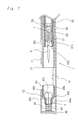
- the first suture needle-holding means 4 may be a suture needle-holding assembly as illustrated in Fig. 7.
- the suture needle-holding assembly 4 comprises a flexible slit hollow member 43 having a needle-holding portion with an inner diameter slightly smaller than the suture needle 6 and including an enlarged head portion 432 provided at a distal end thereof, a hollow clamping member 44 movably mounted on the hollow member 43 to surround the enlarged head portion 432, and a coil spring 45 arranged around the hollow member 43 on the side of the proximal end of the hollow member 43 beyond the clamping member 44.
- the above hollow member 43 is provided at a distal end thereof with an enlarged head portion 432, and fixed at the distal end thereof to a closure member 46.
- the hollow member 43 is provided with plural longitudinal slits 431 at the distal end side of hollow member 43 including the enlarged head portion 432.
- the clamping member 44 is a stepped hollow cylindrical member including a small-sized proximal portion 44a, a large-sized distal portion 44b surrounding the enlarged head portion 432 of the hollow member 43, and a middle portion 44c having an inner diameter tapered from the distal portion to the proximal portion.
- the large-sized distal portion of the clamping member 44 has an inner diameter greater than the outer diameter of the enlarged head portion 432 but slightly smaller than the inner diameter of the gripper holding portion 13, which is then tapered toward the small-sized proximal portion of the clamping member 44.
- the small-sized proximal portion of the clamping member 44 has an inner diameter slightly larger than the outer diameter of the proximal end of the hollow member 43.
- the clamping member 44 is housed in the gripper holding portion 13 together with the hollow member 43.
- the coil spring 45 is located between the closing member 46 and clamping member 44 to force the clamping member 44 toward the distal end of the hollow member 43.
- the clamping member 44 is movable between a first position (or an initial position) where it compresses the hollow member 43, and a second position where it releases the hollow member 43 from compression (i.e., a position where an outer wall of the enlarged head portion 432 is free from contact with an inner wall of the clamping member 44 as the clamping member 44 is moved toward the distal end of the gripper holding portion 13 under compression of the coil spring 45).
- the hollow members 41 and 43 of the fist suture needle-holding means 4 may be made of the material such as metals including stainless steel, brass and the like; and flexible resins including polypropylene, polyethylene, polyamide and the like.
- the needle loading port 42 may be made of materials such as synthetic resins including fluororesin (e.g., polytetrafluoroethylene), polypropylene, polyethylene, polyamide, polyethylene terephthalate, polyurethane and the like.
- the clamping member 44 may be made of the same materials as those used for the hollow members 41 and 43.
- the second shaft assembly 2 comprises a slender second shaft 21 having a lumen 211 passing therethrough from a distal end thereof to a proximal end thereof; and a connector attached to the proximal end of the second shaft 21 and having a hemostatic valve provided therein.
- the second shaft 21 is adapted to be slidably moved toward the first suture needle-holding means 4.
- the second shaft 21 is a slender hollow tubular member and made of the same material as that used for the first shaft 11.
- the lumen 211 extending from the proximal end to the distal end of the second shaft 21 is adapted to receive a third shaft assembly 3 (in fact, a third shaft 31) inserted through the connector 22.
- the connector 22 is a tubular member made of the same material as that of the connector 12, and is provided at a proximal end thereof with a port 221 for loading the third shaft 311 thereinto.
- the connector 22 includes a hemostatic means provided therein (not illustrated in the drawings) for preventing the blood from leakage during operation.
- the third shaft assembly 3 comprises a hollow third shaft 31, and a handling portion 33 attached to a proximal end of the third shaft 31.
- the third shaft 31 is a slender tubular member made of the same material as that of the first shaft 11 and having a lumen 311 passing therethrough from a distal end thereof to a proximal end thereof.
- the third shaft 31 is provided at the proximal end thereof with the handling portion 33 for actuating it back and forth by sliding movement, through which an operating rod 52 of a after-mentioned second suture needle-holding means 51 is inserted movably back and forth.
- the puncture assembly 5 is slidably arranged in the third shaft assembly 3.
- the puncture assembly 5 comprises a slender hollow operating rod 52 having a distal end and a proximal end and provided at the distal end thereof with a second suture needle-holding means 51.
- the second suture needle-holding means 51 is positioned in the distal end of the third shaft 31 and adapted to be put in and out the lumen 311 of the third shaft 31.
- the operating rod 52 is movably arranged in the lumen 311 of the third shaft 31.
- the second suture needle-holding means 51 comprises a flexible hollow member 55 having an inner diameter slightly larger than the diameter of the suture needle 6 and an outer diameter smaller than the inner diameter of the third shaft 31.
- the hollow member 55 is provided at the distal end thereof with an enlarged head portion 552, which is extended from the hollow member 55, reversely tapered toward the distal end thereof and reached to a uniform outer diameter greater than the inner diameter of the third shaft 31.
- the hollow member 55 is provided with plural slits 551 longitudinally extending from the distal end of the enlarged head portion 552 towards the proximal end of hollow member 55.
- the hollow member 55 is fixed at the proximal end thereof to the hollow operating rod 52 slidably arranged in the lumen 311 of the third shaft 31.
- the enlarged head portion 552 is adapted to hold the suture needle 6 therein by reduction of the inner diameter thereof when the enlarged head portion 552 is housed in the third shaft 31.
- the third shaft 31 is preferably provided with an annular rib 312 at the distal portion of the lumen 311 thereof to prevent the enlarged head portion 552 from movement toward the proximal thereof at the time of seating of the enlarged head portion 552 in the third shaft 31.
- the enlarged head portion 552 When the enlarged head portion 552 is pushed out of the lumen of the third shaft 31, the enlarged head portion 552 may be return to the lumen of the third shaft 31 by manually operating the operating rod 52. Alternately, the enlarged head portion 552 may be returned automatically to its original position by providing an auto-return mechanism, which comprises, for example, a flange 553 provided at the proximal end of the hollow member 55, and a coil spring 53 arranged around the hollow member 55 and between the flange 553 and the annular rib 312 so that the coil spring 53 is compressed when the operating rod 52 is pushed forward in the third shaft 31, and then restored by the restoring force of the coil spring 53 to automatically house the enlarged head portion 552 to the lumen 311 of the third shaft 31, as illustrated in Figs. 6 and 7.
- an auto-return mechanism which comprises, for example, a flange 553 provided at the proximal end of the hollow member 55, and a coil spring 53 arranged around the hollow member 55
- the operating rod 52 may be provided at a proximal end thereof with a handling portion 54, which is adapted to be moved forward and backward with respect to the handling portion 33 of the third shaft assembly 3.
- the suture needle 6 is transferred between the first suture needle-holding means 4 and the second suture needle-holding means 51 when the third shaft 31 is moved to the distal end of the second shaft 21 that had been moved beyond the distal end of the first shaft 1 to a position where a suture site is held between the second shaft 21 and the first suture needle-holding means 4.
- the intracardiac suture device of the present invention may be provided with a visual monitoring means such as an endoscope 8, a ultrasound probe (not illustrated in the drawings) or the like, to check the position of the suture device in the heart.
- a visual monitoring means such as an endoscope 8, a ultrasound probe (not illustrated in the drawings) or the like, to check the position of the suture device in the heart.
- the connector 12 of the first shaft assembly 1 or the connector 22 of the second shaft assembly 2 may be provided with a side tube 222 for infusion of heparin, saline for irrigation and the like.
- the hollow member 55 of the second suture needle-holding means 51 may be made of, without being limited to, the same materials as those used for the hollow member 43 of the first suture needle-holding means 4 as the hollow member 55 has the same structure and function as those of the hollow member 43 of the first suture needle-holding means 4.
- closure of defects may be carried out in the manner mentioned below with reference to Figs. 8 to 15.
- the heart is exposed by surgical incision of the chest of a patient and punctured at an appropriate part of the heart (usually, the right auricle).
- a sheath (not illustrated in the drawings) for insertion of an intracardiac suture device is inserted near a suture site through the punctured part.
- the intracardiac suture device as illustrated in Fig. 1 is inserted into the sheath until the distal end thereof reaches to the position near the suture site.
- the suture device is set so as to have a positional relationship as illustrated in Figs. 5 and 6 between the third shaft 31 and the second suture needle-holding means 51.
- the distal end of the suture device is protruded from the sheath to locate the first suture needle-holding means 4 within a defect aperture DA of the heart so that the notch 14 is located in the defect aperture.
- the second shaft assembly 2 is pushed manually over the first shaft assembly 1 to hold a tissue T surrounding the defect aperture DA between the distal end of the second shaft 21 and the gripper holding portion 13. If necessary, this procedure may be carried out with checking out the relationship between the device and the suture site in the heart with the visual means such as the endoscope 8. At that time, the third shaft assembly 3 moves forward along with the second shaft assembly 2 (cf. Fig. 9).
- the first shaft assembly 1 is manually pushed forward over the second shaft assembly 2 as it stands, with the result that the suture needle 6 is moved forward along with the first suture needle-holding means 4, passed through the tissue T, and transferred to the first suture needle-holding means 4 on the opposite side of the second suture needle-holding means 51 with respect to the tissue T, as illustrated in Fig. 12.
- the whole suture device is moved backward to a certain extent and the handling portion 54 of the puncture assembly 5 is taken off while holding the handling portion 33 as it stands. And then the second suture needle holding means 51 is moved backward by the restoring force of the coil spring 53 and the enlarged head portion 552 is pulled in the lumen 311 of the third shaft 31.
- the tissue T is brought out from the notched portion 14 by manipulating the whole of the suture device, as illustrated in Fig. 13. Under the conditions of Fig. 13, the second shaft assembly 2 is pushed manually forward to the position near the distal end of the first shaft assembly 1, which is the same position as that illustrated in Fig.
- the handling portion 33 is moved backward to the handling portion 54 of the puncture assembly 5, so that the enlarged head portion 552 is unsheathed from the third shaft 31 and the hollow member 55 is released from the compression pressure of the third shaft 31.
- the hollow member 55 is returned to the uncompressed condition where the inner diameter of the hollow member 55 is larger than the outer diameter of the suture needle 6.
- the closure of defect is completed by repeating the above procedures several times, and carrying out ligature and cutting of the suture with a special purpose device.
- the use of the intracardiac suture device of the present invention makes it possible to perform a minimally invasive operation for suturing intracardiac defects without use of any artificial heart-lung system.
- the present invention makes it possible to perform intracardiac operations certainly and safely at a lower cost as compared with the conventional operations using any artificial heart-lung system.
- the present invention makes it possible to minimize risk of complications after the operation since the recovery time after operation is reduced to about one day, which is very short as compared with the recovery time of more than one week.
- the present device is easy to operate and contribute to reduce burdens for an operator.
Abstract
Description
- The present invention relates to an intracardiac suture device for use in treatment of intracardiac defects by suturing the defective portion with a suture needle.
- For treatments of intracardiac defects such as atrial septal defect, ventricular septal defect and valvular disease, it is general practice to perform surgical operations with an artificial heart-lung machine (i.e., an extracorporeal circulation system). The heart-lung machine is a device, which performs hemoperfusion instead of the heart of a patient during the stopped period of the pumping action of the heart and acts the breathing function for the lung by prosecution of the gas exchange in the blood. The heart-lung machine generally comprises four main components, i.e., a blood pump, an oxygenator, a heat exchanger and a reservoir. The heart-lung machines have been used widely as auxiliary measures for extracorporeal circulation in open heart surgery. Further, they have also been used as auxiliary measures for supplementary circulation when any bad circulation of the internal organ and/or organization arises from considerable decrease in the pumping action of the heart, or auxiliary measures for gas exchange when the function of the patient's lung is considerably damaged. In addition, the lung-heart machines are used in membrane oxygenator-assisted extracorporeal circulation (ECMO), and as auxiliary measures for extracorporeal circulation in thoracic aortic aneurysm surgery.
- In the first era of cardiac surgery, surgical operations of pulsating hearts have been carried out blindly by the feel and thus the safety has come up as a serious problem before development of an artificial heart-lung machine. In 1953, Dr. Gibbon succeeded in a first cardiac surgery with an artificial heart-lung machine. From that time, the safety of the cardiac surgery has been improved by various improvements in heart-lung machines and development of myocardial depressants. Now, the use of extracorporeal circulation makes it possible to perform the cardiac surgery safely.
- However, even at the present state of the art, the cardiac surgeries with the heart-lung machines are at risk for the following postoperative complications:
- (1) Complication in the brain: Cerebral hypoxemia or cerebral edema resulting from incorrect perfusion. Cerebral infarction due to embolization by of tissue fragments into the blood caused by interfusion of intake-air into extracorporeal circulation in the heart-lung machine or by operation to connect the heart-lung machine to the patient.
- (2) Complication in the lung: hypoxemia or ventilatory insufficiency caused by various inflammentory substances, which are activated by the heart-lung machine.
- (3) Renal dysfunction: Acute renal failure caused by decrease in renal blood flow due to use of the heart-lung machine.
- (4) Blood cell injuries: Blood cell injuries are taken place by performing perfusion of the blood into the artificial, i.e., heart-lung machine. This may cause renal dysfunction, resulting in necessity of blood infusion.
- (5) Postoperative bleeding: Postoperative bleeding may occur by the disorder of the in-vivo hemostatic function caused by the heart-lung machine.
- (6) Aortic dissection: By insertion of an arterial inflow cannula into the aorta, the endothelium of the blood vessel may be injured and induced the acute aortic dissection. This complication is extremely serious condition and death rate of a patient is high.
- (7) Other complications: Postperative infective diseases and multiple organ failure caused by decrease of immunologic reaction.
-
- It is often the case that these complications cause systemic inflammation even if the patient's condition is not severe and the length of postoperative stay in the hospital takes one week at the least. Further, the artificial circulation passages used in operation is of disposable, a high medical cost presents problems for the patients.
- Recently, a tendency to avoid the side effects due to use of the artificial hear-lung is seen in the field of coronary artery bypass, and operations without use of the artificial hear-lung machine have been popularized. In particularly, minimally invasive surgery employing an endoscope is widely used and has become of major interest lately because of low occurence of complications and rapid recovery after operation.
- Even in the field of cardiac surgery, there is an increasing demand for intracardiac surgeries which can be performed without use of any hear-lung machine. It is however, impossible to stop the beat of the heart. Further, it is pointed out that there would be considerable difficulty in use of the endoscope since the blood and beating heart obstructs the view from the endoscope.
- Commercially available catheter devices such as "Amplatzer" (brand name), "Angelwing" (brand name) are applied for treatment of atrial septal defects. These devices are designed for uniformly distributed defects as targets. Thus, it is difficult with such devices to treat the intracardiac defects since these defects vary with the individual patient. For these reasons, there is a great demand for any breakthrough for realizing cardiac surgery without use of any artificial heart-lung machine.
- It is therefore an object of the present invention to provide an intracardiac suture device for performing minimally invasive cardiac surgery on intracardiac defects without use of any artificial heart-lung system.
- The present invention has been made on the basis of a method of introducing a suture device into the heart of a patient through a sheath after surgically incising the chest region of a patent.
- According to the present invention, there is provided an intracardiac suture device, comprising:
- a first shaft assembly comprising a first shaft having a lumen passing therethrough from a proximal end to a distal end thereof, a first suture needle-holding means coaxially provided at and spaced from the distal end of the first shaft, and a connector with a hemostatic valve provided on the proximal end of the first shaft;
- a second shaft assembly comprising a second shaft having a lumen passing therethrough from a proximal end to a distal end thereof and being slidably arranged in the first shaft assembly, and a connector with a hemostatic valve and provided on the proximal end of the second shaft;
- a third shaft assembly comprising a hollow third shaft slidably arranged in the second shaft assembly, and handling portion provided at a proximal end of the third shaft; and
- a puncture assembly comprising a hollow operating rod provided at a proximal end thereof, and a second suture needle-holding means provided at a distal end thereof and removably arranged in the distal end of the third shaft, said hollow operating rod being connected to the proximal end of the second suture needle-holding means and movably arranged in the third shaft assembly; wherein said second shaft is protrusible by sliding-movement from the distal end of the first shaft toward the first suture needle-holding means, and wherein a suture needle is transferable between the first suture needle-holding means and the second suture needle-holding means when the third shaft is slid to the distal end of the second shaft after sliding the second shaft to a position where a suture site is held between the second shaft and the first suture needle-holding means.
-
- In one embodiment of the present invention, the second suture needle-holding means comprises a flexible hollow member with an inner diameter slightly larger than an outer diameter of a suture needle, and the hollow member is provided with an enlarged head portion having a proximal end thereof with an outer diameter smaller than the inner diameter of the third shaft, and a distal end with an outer diameter larger than the inner diameter of the third shaft. The enlarged head portion includes a portion tapered toward the proximal end thereof. The hollow member is provided with plural slits at the distal portion thereof including said enlarged head portion, so that the enlarged head portion is reduced in inner diameter thereof to hold the suture needle when the enlarged head portion is received in the third shaft. In this case, the third shaft is preferably provided with an annular rib at a distal portion of the lumen thereof so that the enlarged head portion is prevented from movement toward the proximal end thereof when the enlarged head portion is housed in the third shaft.
- Further, the hollow member may be provided at a proximal end thereof with a flange and a coil spring arranged around the hollow member and between the flange and the annular rib, so that the operating rod is automatically moved backward by the restoring force of the coil spring, which has been compressed by forward movement of the operation rod.
- In order to improve the operationality of the second suture needle-holding means, the operating rod may be provided at a proximal end thereof with a handling portion, which is adapted to be moved forward and backward with respect to the handling portion of the third shaft assembly.
- In one embodiment of the present invention, the first suture needle-holding means comprises a flexible hollow member having a needle-holding portion with an inner diameter slightly smaller than the suture needle. The hollow member is provided at an end of the first shaft side or a distal end thereof with a needle loading port and at the distal side thereof with plural longitudinally extending slits.
- In another embodiment of the present invention, the first suture needle-holding means comprises a flexible hollow member having a needle-holding portion with an inner diameter slightly smaller than the suture needle and including an enlarged head portion provided at a distal end thereof, a hollow clamping member movably mounted on the hollow member to surround the enlarged head portion, and a coil spring arranged around the hollow member on the proximal end of the hollow member with respect to the clamping member. The hollow member is provided at the distal end side thereof with longitudinal slits. The clamping member is adapted to be moved between a first position where it compresses the hollow member, and a second position where it releases the hollow member from compression.
- The intracardiac suture device may be provided with visual monitoring means for monitoring a position of the device in the heart. Further, the connector of the first or second shaft assembly may be provided with a side tube for infusion of heparin, a saline solution or the like.
- The present invention will be explained below, making reference to the accompanying drawings, which show, by way of example only embodiments thereof.
- Fig. 1 is a plane view illustrating one embodiment of an intracardiac suture device according to the present invention;
- Fig. 2 is a plane view illustrating another embodiment of an intracardiac suture device according to the present invention;
- Fig. 3 is a plane view illustrating another embodiments of an intracardiac suture device according to the present invention;
- Fig. 4 is a sectional view illustrating the suture device of Fig. 1 taken along a line A-A'.
- Fig. 5 is a longitudinal sectional view illustrating the proximal end of the suture device of Fig. 1.
- Fig. 6 is a longitudinal sectional view illustrating the distal end of the suture device of Fig. 1, which includes first and second suture needle holding portions.
- Fig. 7 is a longitudinal sectional view illustrating another embodiment of the distal end of the suture device of Fig. 1, which includes the first suture needle holding portion;
- Figs. 8 to 15 are schematic diagrams illustrating suture operation using the intracardiac suture device of the present invention.
-
- Referring now to Figs. 1 to 7, there is shown an intracardiac suture device according to the present invention, which comprises:
- a first shaft assembly 1 comprising a
first shaft 11 and a first suture needle-holding means 4 provided at a distal end of thefirst shaft 11; - a
second shaft assembly 2 comprising asecond shaft 21 slidably arranged in the first shaft assembly 1; - a
third shaft assembly 3 comprising a hollowthird shaft 31 slidably arranged in thesecond shaft assembly 2 and a handlingportion 33 provided at a proximal end of thethird shaft 31; and - a
puncture assembly 5 provided at a proximal end thereof with a second suture needle-holding means 51, said second suture needle-holding means 51 being removalbly arranged in the distal end of thethird shaft 31;
wherein said -
- As illustrated in Figs. 6 and 7, the first shaft assembly 1 comprises a
first shaft 11 having alumen 111 passing therethrough from a proximal end thereof to a distal end thereof; a first suture needle-holding means 4 coaxially provided at and spaced from the distal end of thefirst shaft 11; and aconnector 12 with a hemostatic valve provided on the proximal end of thefirst shaft 11. - The
first shaft 11 is a tubular member made of a metal such as stainless steel, brass, meshed or coiled stainless steel, or a synthetic resin such as fluororesin(e.g., polytetrafluoroethylene), polypropylene, polyethylene, polyamide, polyethylene terephthalate, polyurethane. Into thelumen 111 passing through thefirst shaft 11 from the distal end thereof to the proximal end thereof, the second shaft assembly 2 (in fact, the second shaft 21) is slidably inserted through theconnector 12 provided on the proximal end of thefirst shaft 11. - The
connector 12 is a tubular member generally made of a synthetic resin such as polypropylene, ABS (acrylonitrile-butadiene-styrene) resin, polyvinyl chloride, polyethylene and polyethylene terephthalate, or a metal such as stainless steel, brass and the like. Theconnector 12 is provided at the proximal end thereof with a port 121 for insertion of thesecond shaft 21, and in an interior thereof with a hemostatic means (not illustrated in the drawings) for preventing leakage of the blood during operation. - The first suture needle-holding
means 4 may be housed in agripper holding portion 13, which is formed as an integral part of a tube forming thefirst shaft 11. In this case, as shown in Figs. 1 to 3, the tube forming thefirst shaft 11 is provided at a distal end thereof with thegripper holding portion 13 spaced by anotch 14 formed between the holdingportion 13 and the distal end of thefirst shaft 11. Thenotch 14 has a predetermined length and a depth sufficiently greater than a radius of thefirst shaft 11. Thegripper holding portion 13 is closed at the distal end thereof by a closingmember 46 to which the first suture needle-holdingmeans 4 is fixed. - The first suture needle-holding
means 4 is arranged in thegripper holding portion 13 such that the distal end thereof is directed to thefirst shaft 11. The first suture needle-holding means (or a first suture needle gripper) 4 may be comprised of, as shown in Fig. 6, a flexiblehollow member 41 having a needle-holding portion with an inner diameter slightly smaller than thesuture needle 6, and aneedle loading port 42 provided on a distal end of said flexiblehollow member 41. Thehollow member 41 is provided withplural slits 411 extending in the longitudinal direction thereof. - Alternatively, the first suture needle-holding
means 4 may be a suture needle-holding assembly as illustrated in Fig. 7. The suture needle-holdingassembly 4 comprises a flexible slithollow member 43 having a needle-holding portion with an inner diameter slightly smaller than thesuture needle 6 and including anenlarged head portion 432 provided at a distal end thereof, ahollow clamping member 44 movably mounted on thehollow member 43 to surround theenlarged head portion 432, and acoil spring 45 arranged around thehollow member 43 on the side of the proximal end of thehollow member 43 beyond the clampingmember 44. The abovehollow member 43 is provided at a distal end thereof with anenlarged head portion 432, and fixed at the distal end thereof to aclosure member 46. Thehollow member 43 is provided with plurallongitudinal slits 431 at the distal end side ofhollow member 43 including theenlarged head portion 432. The clampingmember 44 is a stepped hollow cylindrical member including a small-sizedproximal portion 44a, a large-sizeddistal portion 44b surrounding theenlarged head portion 432 of thehollow member 43, and amiddle portion 44c having an inner diameter tapered from the distal portion to the proximal portion. The large-sized distal portion of the clampingmember 44 has an inner diameter greater than the outer diameter of theenlarged head portion 432 but slightly smaller than the inner diameter of thegripper holding portion 13, which is then tapered toward the small-sized proximal portion of the clampingmember 44. The small-sized proximal portion of the clampingmember 44 has an inner diameter slightly larger than the outer diameter of the proximal end of thehollow member 43. The clampingmember 44 is housed in thegripper holding portion 13 together with thehollow member 43. Thecoil spring 45 is located between the closingmember 46 and clampingmember 44 to force the clampingmember 44 toward the distal end of thehollow member 43. The clampingmember 44 is movable between a first position (or an initial position) where it compresses thehollow member 43, and a second position where it releases thehollow member 43 from compression (i.e., a position where an outer wall of theenlarged head portion 432 is free from contact with an inner wall of the clampingmember 44 as the clampingmember 44 is moved toward the distal end of thegripper holding portion 13 under compression of the coil spring 45). - The
hollow members means 4 may be made of the material such as metals including stainless steel, brass and the like; and flexible resins including polypropylene, polyethylene, polyamide and the like. Theneedle loading port 42 may be made of materials such as synthetic resins including fluororesin (e.g., polytetrafluoroethylene), polypropylene, polyethylene, polyamide, polyethylene terephthalate, polyurethane and the like. The clampingmember 44 may be made of the same materials as those used for thehollow members - As illustrated in Figs. 6 and 7, the
second shaft assembly 2 comprises a slendersecond shaft 21 having alumen 211 passing therethrough from a distal end thereof to a proximal end thereof; and a connector attached to the proximal end of thesecond shaft 21 and having a hemostatic valve provided therein. Thesecond shaft 21 is adapted to be slidably moved toward the first suture needle-holdingmeans 4. Thesecond shaft 21 is a slender hollow tubular member and made of the same material as that used for thefirst shaft 11. Thelumen 211 extending from the proximal end to the distal end of thesecond shaft 21 is adapted to receive a third shaft assembly 3 (in fact, a third shaft 31) inserted through theconnector 22. - The
connector 22 is a tubular member made of the same material as that of theconnector 12, and is provided at a proximal end thereof with aport 221 for loading thethird shaft 311 thereinto. Theconnector 22 includes a hemostatic means provided therein (not illustrated in the drawings) for preventing the blood from leakage during operation. - The
third shaft assembly 3 comprises a hollowthird shaft 31, and a handlingportion 33 attached to a proximal end of thethird shaft 31. Thethird shaft 31 is a slender tubular member made of the same material as that of thefirst shaft 11 and having alumen 311 passing therethrough from a distal end thereof to a proximal end thereof. Thethird shaft 31 is provided at the proximal end thereof with the handlingportion 33 for actuating it back and forth by sliding movement, through which anoperating rod 52 of a after-mentioned second suture needle-holdingmeans 51 is inserted movably back and forth. There is no limit to a material for the handlingportion 33, but the handlingportion 33 is generally made of the same as that used for thethird shaft 31. - The
puncture assembly 5 is slidably arranged in thethird shaft assembly 3. Thepuncture assembly 5 comprises a slenderhollow operating rod 52 having a distal end and a proximal end and provided at the distal end thereof with a second suture needle-holdingmeans 51. The second suture needle-holdingmeans 51 is positioned in the distal end of thethird shaft 31 and adapted to be put in and out thelumen 311 of thethird shaft 31. The operatingrod 52 is movably arranged in thelumen 311 of thethird shaft 31. - The second suture needle-holding
means 51 comprises a flexiblehollow member 55 having an inner diameter slightly larger than the diameter of thesuture needle 6 and an outer diameter smaller than the inner diameter of thethird shaft 31. Thehollow member 55 is provided at the distal end thereof with anenlarged head portion 552, which is extended from thehollow member 55, reversely tapered toward the distal end thereof and reached to a uniform outer diameter greater than the inner diameter of thethird shaft 31. Thehollow member 55 is provided withplural slits 551 longitudinally extending from the distal end of theenlarged head portion 552 towards the proximal end ofhollow member 55. - The
hollow member 55 is fixed at the proximal end thereof to thehollow operating rod 52 slidably arranged in thelumen 311 of thethird shaft 31. Theenlarged head portion 552 is adapted to hold thesuture needle 6 therein by reduction of the inner diameter thereof when theenlarged head portion 552 is housed in thethird shaft 31. In this case, as illustrated in Figs. 6 and 7, thethird shaft 31 is preferably provided with anannular rib 312 at the distal portion of thelumen 311 thereof to prevent theenlarged head portion 552 from movement toward the proximal thereof at the time of seating of theenlarged head portion 552 in thethird shaft 31. - When the
enlarged head portion 552 is pushed out of the lumen of thethird shaft 31, theenlarged head portion 552 may be return to the lumen of thethird shaft 31 by manually operating the operatingrod 52. Alternately, theenlarged head portion 552 may be returned automatically to its original position by providing an auto-return mechanism, which comprises, for example, aflange 553 provided at the proximal end of thehollow member 55, and acoil spring 53 arranged around thehollow member 55 and between theflange 553 and theannular rib 312 so that thecoil spring 53 is compressed when the operatingrod 52 is pushed forward in thethird shaft 31, and then restored by the restoring force of thecoil spring 53 to automatically house theenlarged head portion 552 to thelumen 311 of thethird shaft 31, as illustrated in Figs. 6 and 7. - Further, in order to improve the operationality of the second suture needle-holding means 51, the operating
rod 52 may be provided at a proximal end thereof with a handlingportion 54, which is adapted to be moved forward and backward with respect to the handlingportion 33 of thethird shaft assembly 3. - In the suture device comprised of the first, second and
third shaft assemblies puncture assembly 5, thesuture needle 6 is transferred between the first suture needle-holdingmeans 4 and the second suture needle-holding means 51 when thethird shaft 31 is moved to the distal end of thesecond shaft 21 that had been moved beyond the distal end of the first shaft 1 to a position where a suture site is held between thesecond shaft 21 and the first suture needle-holdingmeans 4. - As illustrated in Fig. 3, the intracardiac suture device of the present invention may be provided with a visual monitoring means such as an endoscope 8, a ultrasound probe (not illustrated in the drawings) or the like, to check the position of the suture device in the heart. Further, as illustrated in Fig. 2, the
connector 12 of the first shaft assembly 1 or theconnector 22 of thesecond shaft assembly 2 may be provided with aside tube 222 for infusion of heparin, saline for irrigation and the like. - The
hollow member 55 of the second suture needle-holding means 51 may be made of, without being limited to, the same materials as those used for thehollow member 43 of the first suture needle-holding means 4 as thehollow member 55 has the same structure and function as those of thehollow member 43 of the first suture needle-holdingmeans 4. - Using the intracardiac suture device of the present invention, closure of defects may be carried out in the manner mentioned below with reference to Figs. 8 to 15.
- Firstly, the heart is exposed by surgical incision of the chest of a patient and punctured at an appropriate part of the heart (usually, the right auricle). A sheath (not illustrated in the drawings) for insertion of an intracardiac suture device is inserted near a suture site through the punctured part. Then, the intracardiac suture device as illustrated in Fig. 1 is inserted into the sheath until the distal end thereof reaches to the position near the suture site. Before insertion, the suture device is set so as to have a positional relationship as illustrated in Figs. 5 and 6 between the
third shaft 31 and the second suture needle-holdingmeans 51. - As illustrated in Fig. 8, the distal end of the suture device is protruded from the sheath to locate the first suture needle-holding means 4 within a defect aperture DA of the heart so that the
notch 14 is located in the defect aperture. Thesecond shaft assembly 2 is pushed manually over the first shaft assembly 1 to hold a tissue T surrounding the defect aperture DA between the distal end of thesecond shaft 21 and thegripper holding portion 13. If necessary, this procedure may be carried out with checking out the relationship between the device and the suture site in the heart with the visual means such as the endoscope 8. At that time, thethird shaft assembly 3 moves forward along with the second shaft assembly 2 (cf. Fig. 9). At a state where the tissue T is held between thegripper holding portion 13 and thesecond shaft 21, when the handlingportion 33 is pushed manually over thesecond shaft assembly 2 and thereby thethird shaft assembly 3 is pushed forward to thesecond shaft assembly 21 with the result that the second puncture needle holding means 51 is moved forward along with thethird shaft 31. Thus, thepuncture needle 6 held by the second puncture needle holding means 51 in thethird shaft 31 is moved forward to puncture the tissue T, inserted into the first suture needle-holdingmeans 4 and received therein at the distal end thereof (cf. Fig. 10). - Then, by retreating the handling
portion 33 toward the handlingportion 54 of thepuncture assembly 5, theenlarged head portion 552 is unsheathed from thethird shaft 31 and thus thehollow member 55 is released from the compression pressure of thethird shaft 31. Thus, thehollow member 55 is returned to the uncompressed condition where the inner diameter of thehollow member 55 is larger than the outer diameter of thesuture needle 6, and thesuture needle 6 is released from the second suture needle-holding means 51 (cf. Fig. 11). At the same time, the backward movement of the handlingportion 33 compresses thecoil spring 53. Under the condition illustrated in Fig. 11, the first shaft assembly 1 is manually pushed forward over thesecond shaft assembly 2 as it stands, with the result that thesuture needle 6 is moved forward along with the first suture needle-holdingmeans 4, passed through the tissue T, and transferred to the first suture needle-holding means 4 on the opposite side of the second suture needle-holding means 51 with respect to the tissue T, as illustrated in Fig. 12. - The whole suture device is moved backward to a certain extent and the handling
portion 54 of thepuncture assembly 5 is taken off while holding the handlingportion 33 as it stands. And then the second suture needle holding means 51 is moved backward by the restoring force of thecoil spring 53 and theenlarged head portion 552 is pulled in thelumen 311 of thethird shaft 31. The tissue T is brought out from the notchedportion 14 by manipulating the whole of the suture device, as illustrated in Fig. 13. Under the conditions of Fig. 13, thesecond shaft assembly 2 is pushed manually forward to the position near the distal end of the first shaft assembly 1, which is the same position as that illustrated in Fig. 9, and then the handlingportion 33 is moved backward to the handlingportion 54 of thepuncture assembly 5, so that theenlarged head portion 552 is unsheathed from thethird shaft 31 and thehollow member 55 is released from the compression pressure of thethird shaft 31. Thus, thehollow member 55 is returned to the uncompressed condition where the inner diameter of thehollow member 55 is larger than the outer diameter of thesuture needle 6. Under such a condition, by pushing the handlingportion 33 to advance thethird shaft assembly 3 over thesecond shaft assembly 2, thesuture needle 6 is received by the second suture needle-holding means 51 as illustrated in Fig. 14. At that time, thecoil spring 6 is being compressed. - Then, by losing hold of the handling
portion 33 while holding thesecond shaft assembly 2 and the handlingportion 54 of thepuncture assembly 5, thethird shaft assembly 3 is moved forward by the restoring force of thecoil spring 53. For this reason, theenlarged head portion 552 is received in thethird shaft 31 and thehollow member 55 is compressed by thethird shaft 31 to make the inner diameter of thehollow member 55 smaller than the outer diameter of thesuture needle 6, so that thesuture needle 6 is held by the suture needle holding means 51. Under such a condition, when the first shaft assembly 1 is pushed forward to move it over thesecond shaft assembly 2, thesuture needle 6 is transferred to the second suture needle holding means 51 and brought to the condition as illustrated in Fig. 15. - The closure of defect is completed by repeating the above procedures several times, and carrying out ligature and cutting of the suture with a special purpose device.
- As will be understood from the above description, the use of the intracardiac suture device of the present invention makes it possible to perform a minimally invasive operation for suturing intracardiac defects without use of any artificial heart-lung system.
- Further, the present invention makes it possible to perform intracardiac operations certainly and safely at a lower cost as compared with the conventional operations using any artificial heart-lung system. In addition, the present invention makes it possible to minimize risk of complications after the operation since the recovery time after operation is reduced to about one day, which is very short as compared with the recovery time of more than one week. Also, the present device is easy to operate and contribute to reduce burdens for an operator.
Claims (9)
- An intracardiac suture device, comprising:wherein said second shaft is protrusible by sliding-movement from the distal end of the first shaft toward the first suture needle-holding means, and wherein a suture needle is transferable between the first suture needle-holding means and the second suture needle-holding means when the third shaft is slid to the distal end of the second shaft after sliding the second shaft to a position where a suture site is held between the second shaft and the first suture needle-holding means.a first shaft assembly comprising a first shaft having a lumen passing therethrough from a proximal end to a distal end thereof, a first suture needle-holding means coaxially provided at and spaced from the distal end of the first shaft, and a connector with a hemostatic valve provided on the proximal end of the first shaft;a second shaft assembly comprising a second shaft having a lumen passing therethrough from a proximal end to a distal end thereof and being slidably arranged in the first shaft assembly, and a connector with a hemostatic valve provided on the proximal end of the second shaft;a third shaft assembly comprising a hollow third shaft slidably arranged in the second shaft assembly, and handling portion provided at a proximal end of the third shaft; anda puncture assembly comprising a hollow operating rod provided at a proximal end thereof, and a second suture needle-holding means provided at a distal end thereof and removably arranged in the distal end of the third shaft, said hollow operating rod being connected to the proximal end of the second suture needle-holding means and movably arranged in the third shaft assembly;
- The intracardiac suture device according to claim 1, wherein the second suture needle-holding means comprises a flexible hollow member with an inner diameter slightly larger than an outer diameter of a suture needle, said hollow member being provided with an enlarged head portion having a proximal end with an outer diameter smaller than the inner diameter of the third shaft, and a distal end with an outer diameter larger than the inner diameter of the third shaft, wherein said enlarged head portion includes a portion tapered toward the proximal end thereof, and wherein said hollow member is provided with plural slits at the distal portion thereof including said enlarged head portion, so that the enlarged head portion is reduced in inner diameter thereof to hold the suture needle when the enlarged head portion is received in the third shaft.
- The intracardiac suture device according to claim 2, wherein the third shaft is provided with an annular rib at a distal portion of the lumen thereof so that the enlarged head portion is prevented from movement toward the proximal end thereof when the enlarged head portion is housed in the third shaft.
- The intracardiac suture device according to claim 3, further including a flange provided at a proximal end of the hollow member and a coil spring arranged around said hollow member and between the flange and the annular rib, wherein the operating rod, which has been moved forward by operation followed with compression of the coil spring, is automatically moved backward by the restoring force of the coil spring.
- The intracardiac suture device according to any of claims 1 to 4, wherein the operating rod is provided at a proximal end thereof with a handling portion adapted to be movable forward and backward over the handling portion of the third shaft assembly.
- The intracardiac suture device according to any of claims 1 to 5, wherein the first suture needle-holding means comprises a flexible hollow member having a needle-holding portion with an inner diameter slightly smaller than the suture needle, and a needle loading port provided at an end of the first shaft side or a distal end of said flexible hollow member, said hollow member being provided with plural slits extending in the longitudinal direction thereof.
- The intracardiac suture device according to any of claims 1 to 5, wherein the first suture needle-holding means comprises a flexible hollow member having a needle-holding portion with an inner diameter slightly smaller than the suture needle and being provided at a distal end thereof with an enlarged head portion, a hollow clamping member movably mounted on the distal side of the hollow member and adapted to surround the enlarged head portion, and a coil spring arranged around the hollow member on the proximal side of said hollow member with respect to the clamping member, the hollow member 43 being provided at the distal end side thereof with longitudinal slits.
- The intracardiac suture device according to any of claims 1 to 7, further including visual monitoring means for monitoring a position of the device in the heart.
- The intracardiac suture device according to claim 6 or 7, wherein the connector of the first or second shaft assembly is provided with a side tube for infusion of heparin, a saline solution or the like.
Applications Claiming Priority (2)
| Application Number | Priority Date | Filing Date | Title |
|---|---|---|---|
| JP2001305667A JP3921681B2 (en) | 2001-10-01 | 2001-10-01 | Intracardiac suture device |
| JP2001305667 | 2001-10-01 |
Publications (2)
| Publication Number | Publication Date |
|---|---|
| EP1297787A1 true EP1297787A1 (en) | 2003-04-02 |
| EP1297787B1 EP1297787B1 (en) | 2004-08-18 |
Family
ID=19125419
Family Applications (1)
| Application Number | Title | Priority Date | Filing Date |
|---|---|---|---|
| EP02021781A Expired - Lifetime EP1297787B1 (en) | 2001-10-01 | 2002-09-26 | Intracardiac suture device |
Country Status (6)
| Country | Link |
|---|---|
| US (1) | US6991635B2 (en) |
| EP (1) | EP1297787B1 (en) |
| JP (1) | JP3921681B2 (en) |
| CN (1) | CN100435742C (en) |
| AT (1) | ATE273659T1 (en) |
| DE (1) | DE60200998T2 (en) |
Cited By (3)
| Publication number | Priority date | Publication date | Assignee | Title |
|---|---|---|---|---|
| EP1354558A2 (en) * | 2002-04-15 | 2003-10-22 | Nipro Corporation | Intracardiac suture device |
| WO2010019973A1 (en) * | 2008-08-19 | 2010-02-25 | A.M.I. Agency For Medical Innovations Gmbh | Surgical device |
| CN112218589A (en) * | 2018-05-29 | 2021-01-12 | 易缝合股份有限公司 | Biological tissue access and closure devices, systems, and methods |
Families Citing this family (205)
| Publication number | Priority date | Publication date | Assignee | Title |
|---|---|---|---|---|
| US7083628B2 (en) | 2002-09-03 | 2006-08-01 | Edwards Lifesciences Corporation | Single catheter mitral valve repair device and method for use |
| ES2435094T3 (en) * | 2000-05-19 | 2013-12-18 | C.R. Bard, Inc. | Device and method of tissue capture and suturing |
| DE60117977D1 (en) * | 2000-06-05 | 2006-05-11 | Boston Scient Ltd | DEVICES FOR TREATING HARNINE CONTINENCE |
| US8915927B2 (en) * | 2001-03-09 | 2014-12-23 | Boston Scientific Scimed, Inc. | Systems, methods and devices relating to delivery of medical implants |
| US9149261B2 (en) | 2001-03-09 | 2015-10-06 | Boston Scientific Scimed, Inc. | Systems, methods and devices relating to delivery of medical implants |
| US6702835B2 (en) | 2001-09-07 | 2004-03-09 | Core Medical, Inc. | Needle apparatus for closing septal defects and methods for using such apparatus |
| US20080015633A1 (en) * | 2001-09-06 | 2008-01-17 | Ryan Abbott | Systems and Methods for Treating Septal Defects |
| US20090054912A1 (en) * | 2001-09-06 | 2009-02-26 | Heanue Taylor A | Systems and Methods for Treating Septal Defects |
| US20070129755A1 (en) * | 2005-12-05 | 2007-06-07 | Ovalis, Inc. | Clip-based systems and methods for treating septal defects |
| US6776784B2 (en) * | 2001-09-06 | 2004-08-17 | Core Medical, Inc. | Clip apparatus for closing septal defects and methods of use |
| US20050267495A1 (en) * | 2004-05-17 | 2005-12-01 | Gateway Medical, Inc. | Systems and methods for closing internal tissue defects |
| US20060052821A1 (en) * | 2001-09-06 | 2006-03-09 | Ovalis, Inc. | Systems and methods for treating septal defects |
| US20070112358A1 (en) * | 2001-09-06 | 2007-05-17 | Ryan Abbott | Systems and Methods for Treating Septal Defects |
| WO2003086207A1 (en) * | 2002-04-10 | 2003-10-23 | Tyco Healthcare Group, Lp | Surgical clip applier with high torque jaws |
| JP4589867B2 (en) * | 2002-08-14 | 2010-12-01 | ボストン サイエンティフィック リミテッド | System and device for delivery of medical implants |
| EP1608272B1 (en) * | 2003-03-11 | 2017-01-25 | Covidien LP | Clip applying apparatus with angled jaw |
| US20040193213A1 (en) * | 2003-03-11 | 2004-09-30 | Ernest Aranyi | Clip applying apparatus with curved jaws, and clip |
| BRPI0410376B1 (en) * | 2003-05-16 | 2016-06-14 | Bard Inc C R | endoscopic suture system and single intubation |
| AU2004279466A1 (en) * | 2003-10-10 | 2005-04-21 | Proximare, Inc. | Patent foramen ovale (PFO) closure devices, delivery apparatus and related methods and systems |
| US20050192627A1 (en) * | 2003-10-10 | 2005-09-01 | Whisenant Brian K. | Patent foramen ovale closure devices, delivery apparatus and related methods and systems |
| WO2005065554A1 (en) * | 2004-01-08 | 2005-07-21 | Olympus Corporation | Anastomosis device and method of excising wall portion of in vivo luminal organ |
| DE102004041936B3 (en) * | 2004-08-30 | 2005-10-06 | Medi-Globe Gmbh | A surgical device for passing at least two sutures through the edge region of a tissue opening |
| CA2580931C (en) | 2004-09-23 | 2013-05-07 | Tyco Healthcare Group Lp | Clip applying apparatus and ligation clip |
| US9763668B2 (en) | 2004-10-08 | 2017-09-19 | Covidien Lp | Endoscopic surgical clip applier |
| US8920438B2 (en) * | 2004-10-08 | 2014-12-30 | Covidien Lp | Apparatus for applying surgical clips |
| US7819886B2 (en) * | 2004-10-08 | 2010-10-26 | Tyco Healthcare Group Lp | Endoscopic surgical clip applier |
| ES2547214T3 (en) | 2004-10-08 | 2015-10-02 | Covidien Lp | An endoscopic clip or surgical clip applicator |
| US8409222B2 (en) * | 2004-10-08 | 2013-04-02 | Covidien Lp | Endoscopic surgical clip applier |
| AU2006206591B2 (en) | 2005-01-21 | 2011-08-25 | Mayo Foundation For Medical Education And Research | Thorascopic heart valve repair method and apparatus |
| JP5186366B2 (en) | 2005-06-20 | 2013-04-17 | スーチュラ,インコーポレイテッド | Device for knotting sutures |
| US8579936B2 (en) * | 2005-07-05 | 2013-11-12 | ProMed, Inc. | Centering of delivery devices with respect to a septal defect |
| US20070049952A1 (en) * | 2005-08-30 | 2007-03-01 | Weiss Steven J | Apparatus and method for mitral valve repair without cardiopulmonary bypass, including transmural techniques |
| US7846179B2 (en) * | 2005-09-01 | 2010-12-07 | Ovalis, Inc. | Suture-based systems and methods for treating septal defects |
| US7738401B2 (en) * | 2005-10-20 | 2010-06-15 | At&T Intellectual Property I, L.P. | System and method for overlaying a hierarchical network design on a full mesh network |
| US20070089433A1 (en) * | 2005-10-20 | 2007-04-26 | Smurfit-Stone Container Enterprises, Inc. | Methods and systems for monitoring a shelf life of a product stored within a container |
| USD629101S1 (en) | 2006-03-24 | 2010-12-14 | Tyco Healthcare Group Lp | Surgical clip applier |
| USD625009S1 (en) | 2006-03-24 | 2010-10-05 | Tyco Healthcare Group Lp | Surgical clip applier |
| WO2008045376A2 (en) | 2006-10-05 | 2008-04-17 | Tyco Healthcare Group Lp | Axial stitching device |
| US8460275B2 (en) | 2006-10-05 | 2013-06-11 | Covidien Lp | Flexible endoscopic stitching devices |
| EP2314232B1 (en) * | 2006-10-17 | 2015-03-25 | Covidien LP | Apparatus for applying surgical clips |
| WO2008058005A2 (en) * | 2006-11-03 | 2008-05-15 | The Penn State Research Foundation | Endosurgery suturing device |
| DE102006052710A1 (en) * | 2006-11-08 | 2008-05-29 | Siemens Ag | Device for investigation and execution of interventions, puncture and injections in body cavities of human or animal body, has catheter with distal end and two lumens partly parallel to each other |
| EP3189796B1 (en) | 2007-03-26 | 2019-09-25 | Covidien LP | Endoscopic surgical clip applier |
| CN102327136B (en) | 2007-04-11 | 2014-04-23 | 柯惠Lp公司 | Surgical clip applier |
| US20090012538A1 (en) * | 2007-07-03 | 2009-01-08 | Justin Saliman | Methods and devices for continuous suture passing |
| US9861354B2 (en) | 2011-05-06 | 2018-01-09 | Ceterix Orthopaedics, Inc. | Meniscus repair |
| US9314234B2 (en) | 2007-07-03 | 2016-04-19 | Ceterix Orthopaedics, Inc. | Pre-tied surgical knots for use with suture passers |
| US20110130773A1 (en) * | 2007-07-03 | 2011-06-02 | Saliman Justin D | Methods for continuous suture passing |
| US10441273B2 (en) | 2007-07-03 | 2019-10-15 | Ceterix Orthopaedics, Inc. | Pre-tied surgical knots for use with suture passers |
| US8663253B2 (en) * | 2007-07-03 | 2014-03-04 | Ceterix Orthopaedics, Inc. | Methods of meniscus repair |
| US20100130990A1 (en) * | 2007-07-03 | 2010-05-27 | Saliman Justin D | Methods of suturing and repairing tissue using a continuous suture passer device |
| US8911456B2 (en) | 2007-07-03 | 2014-12-16 | Ceterix Orthopaedics, Inc. | Methods and devices for preventing tissue bridging while suturing |
| US8500809B2 (en) | 2011-01-10 | 2013-08-06 | Ceterix Orthopaedics, Inc. | Implant and method for repair of the anterior cruciate ligament |
| US9211119B2 (en) | 2007-07-03 | 2015-12-15 | Ceterix Orthopaedics, Inc. | Suture passers and methods of passing suture |
| US8702731B2 (en) | 2007-07-03 | 2014-04-22 | Ceterix Orthopaedics, Inc. | Suturing and repairing tissue using in vivo suture loading |
| US8465505B2 (en) | 2011-05-06 | 2013-06-18 | Ceterix Orthopaedics, Inc. | Suture passer devices and methods |
| EP2219530B1 (en) | 2007-10-18 | 2013-06-19 | Neochord Inc. | A device for minimially invasive repair of a valve leaflet in a beating heart |
| EP2211725A4 (en) * | 2007-11-05 | 2015-04-01 | Ceterix Orthopedics Inc | Suture passing instrument and method |
| JP2011502587A (en) * | 2007-11-07 | 2011-01-27 | オバリス, インコーポレイテッド | System, apparatus and method for transverse orientation in septal defect treatment |
| US8864776B2 (en) * | 2008-04-11 | 2014-10-21 | Covidien Lp | Deployment system for surgical suture |
| AU2009249063A1 (en) * | 2008-05-20 | 2009-11-26 | Ovalis, Inc. | Wire-like and other devices for treating septal defects and systems and methods for delivering the same |
| US20090306685A1 (en) * | 2008-06-10 | 2009-12-10 | Ension, Inc. | Noninvasive trans-catheter method and apparatus for remote suture placement such as for septal defect repair, left atrial appendage closure, pacemaker electrode placement, mitral valve repair, and other inner-cardiac and inner-arterial applications |
| US8628545B2 (en) * | 2008-06-13 | 2014-01-14 | Covidien Lp | Endoscopic stitching devices |
| US20110040308A1 (en) | 2008-06-13 | 2011-02-17 | Ramiro Cabrera | Endoscopic Stitching Devices |
| US20110208212A1 (en) | 2010-02-19 | 2011-08-25 | Zergiebel Earl M | Surgical clip applier |
| US8056565B2 (en) | 2008-08-25 | 2011-11-15 | Tyco Healthcare Group Lp | Surgical clip applier and method of assembly |
| US8465502B2 (en) | 2008-08-25 | 2013-06-18 | Covidien Lp | Surgical clip applier and method of assembly |
| US8585717B2 (en) * | 2008-08-29 | 2013-11-19 | Covidien Lp | Single stroke endoscopic surgical clip applier |
| US9358015B2 (en) | 2008-08-29 | 2016-06-07 | Covidien Lp | Endoscopic surgical clip applier with wedge plate |
| US8267944B2 (en) | 2008-08-29 | 2012-09-18 | Tyco Healthcare Group Lp | Endoscopic surgical clip applier with lock out |
| US8409223B2 (en) | 2008-08-29 | 2013-04-02 | Covidien Lp | Endoscopic surgical clip applier with clip retention |
| EP2389118B1 (en) * | 2009-01-26 | 2019-05-15 | Synthes GmbH | Bi-directional suture passer |
| US9943306B2 (en) | 2009-04-14 | 2018-04-17 | Covidien Lp | Knotless endostitch suture retainer |
| USD708746S1 (en) | 2009-06-10 | 2014-07-08 | Covidien Lp | Handle for surgical device |
| US8591529B2 (en) | 2009-10-01 | 2013-11-26 | Covidien Lp | Wound closure device including direct-driven needle |
| US8490713B2 (en) | 2009-10-06 | 2013-07-23 | Covidien Lp | Handle assembly for endoscopic suturing device |
| US8734469B2 (en) | 2009-10-13 | 2014-05-27 | Covidien Lp | Suture clip applier |
| US9011454B2 (en) | 2009-11-09 | 2015-04-21 | Ceterix Orthopaedics, Inc. | Suture passer with radiused upper jaw |
| US9848868B2 (en) | 2011-01-10 | 2017-12-26 | Ceterix Orthopaedics, Inc. | Suture methods for forming locking loops stitches |
| US11744575B2 (en) | 2009-11-09 | 2023-09-05 | Ceterix Orthopaedics, Inc. | Suture passer devices and methods |
| WO2011057245A2 (en) | 2009-11-09 | 2011-05-12 | Suturepro Technologies, Inc. | Devices, systems and methods for meniscus repair |
| US9186136B2 (en) | 2009-12-09 | 2015-11-17 | Covidien Lp | Surgical clip applier |
| US8545486B2 (en) * | 2009-12-15 | 2013-10-01 | Covidien Lp | Surgical clip applier |
| US8403945B2 (en) | 2010-02-25 | 2013-03-26 | Covidien Lp | Articulating endoscopic surgical clip applier |
| JP2013525083A (en) * | 2010-05-06 | 2013-06-20 | ジンテス ゲゼルシャフト ミット ベシュレンクテル ハフツング | Soft tissue defect device and related methods |
| US8403946B2 (en) | 2010-07-28 | 2013-03-26 | Covidien Lp | Articulating clip applier cartridge |
| US8968337B2 (en) | 2010-07-28 | 2015-03-03 | Covidien Lp | Articulating clip applier |
| US9011464B2 (en) | 2010-11-02 | 2015-04-21 | Covidien Lp | Self-centering clip and jaw |
| CN103347464B (en) | 2010-12-29 | 2016-02-03 | 尼奥绰德有限公司 | The replaceable system of beating heart valve leaflet is repaired by Wicresoft |
| US9913638B2 (en) | 2011-01-10 | 2018-03-13 | Ceterix Orthopaedics, Inc. | Transosteal anchoring methods for tissue repair |
| US8864777B2 (en) | 2011-01-28 | 2014-10-21 | Anchor Orthopedics Xt Inc. | Methods for facilitating tissue puncture |
| US9186153B2 (en) | 2011-01-31 | 2015-11-17 | Covidien Lp | Locking cam driver and jaw assembly for clip applier |
| US8968340B2 (en) | 2011-02-23 | 2015-03-03 | Covidien Lp | Single actuating jaw flexible endolumenal stitching device |
| US9775623B2 (en) | 2011-04-29 | 2017-10-03 | Covidien Lp | Surgical clip applier including clip relief feature |
| WO2012167120A2 (en) | 2011-06-01 | 2012-12-06 | Neochord, Inc. | Minimally invasive repair of heart valve leaflets |
| EP2723277B1 (en) | 2011-06-27 | 2018-05-30 | University of Maryland, Baltimore | Transapical mitral valve repair device |
| EP3868308A3 (en) | 2011-08-18 | 2021-09-15 | Anchor Orthopedics XT Inc. | Suture trap |
| US10524778B2 (en) | 2011-09-28 | 2020-01-07 | Ceterix Orthopaedics | Suture passers adapted for use in constrained regions |
| US20130131697A1 (en) | 2011-11-21 | 2013-05-23 | Covidien Lp | Surgical clip applier |
| US9364239B2 (en) | 2011-12-19 | 2016-06-14 | Covidien Lp | Jaw closure mechanism for a surgical clip applier |
| US9364216B2 (en) | 2011-12-29 | 2016-06-14 | Covidien Lp | Surgical clip applier with integrated clip counter |
| US9408610B2 (en) | 2012-05-04 | 2016-08-09 | Covidien Lp | Surgical clip applier with dissector |
| US9532787B2 (en) | 2012-05-31 | 2017-01-03 | Covidien Lp | Endoscopic clip applier |
| US9113892B2 (en) | 2013-01-08 | 2015-08-25 | Covidien Lp | Surgical clip applier |
| US9968362B2 (en) | 2013-01-08 | 2018-05-15 | Covidien Lp | Surgical clip applier |
| US9750500B2 (en) | 2013-01-18 | 2017-09-05 | Covidien Lp | Surgical clip applier |
| US9579098B2 (en) | 2013-03-15 | 2017-02-28 | King Saud University | Bendable suture needle with free varying angle and holder therefor |
| US20140276979A1 (en) | 2013-03-15 | 2014-09-18 | Lsi Solutions, Inc. | Method and devices for securing bidirectional suture loops using coaxial mechanical fasteners |
| US9775624B2 (en) | 2013-08-27 | 2017-10-03 | Covidien Lp | Surgical clip applier |
| US9247935B2 (en) | 2013-09-23 | 2016-02-02 | Ceterix Orthopaedics, Inc. | Arthroscopic knot pusher and suture cutter |
| US10512458B2 (en) | 2013-12-06 | 2019-12-24 | Med-Venture Investments, Llc | Suturing methods and apparatuses |
| CN104939875B (en) | 2013-12-16 | 2019-07-26 | 赛特里克斯整形公司 | Automatically suture passer device and method are reloaded |
| US9681864B1 (en) | 2014-01-03 | 2017-06-20 | Harpoon Medical, Inc. | Method and apparatus for transapical procedures on a mitral valve |
| EP2929841B1 (en) | 2014-04-08 | 2017-11-15 | Ceterix Orthopaedics, Inc. | Suture passers adapted for use in constrained regions |
| US9468434B2 (en) | 2014-06-03 | 2016-10-18 | Covidien Lp | Stitching end effector |
| US10702278B2 (en) | 2014-12-02 | 2020-07-07 | Covidien Lp | Laparoscopic surgical ligation clip applier |
| US10231723B2 (en) * | 2014-12-15 | 2019-03-19 | Lsi Solutions, Inc. | Surgical rib cutter and methods thereof |
| US9931124B2 (en) | 2015-01-07 | 2018-04-03 | Covidien Lp | Reposable clip applier |
| US10368876B2 (en) | 2015-01-15 | 2019-08-06 | Covidien Lp | Endoscopic reposable surgical clip applier |
| US10292712B2 (en) | 2015-01-28 | 2019-05-21 | Covidien Lp | Surgical clip applier with integrated cutter |
| US10159491B2 (en) | 2015-03-10 | 2018-12-25 | Covidien Lp | Endoscopic reposable surgical clip applier |
| US10092286B2 (en) | 2015-05-27 | 2018-10-09 | Covidien Lp | Suturing loading unit |
| US10226245B2 (en) | 2015-07-21 | 2019-03-12 | Ceterix Orthopaedics, Inc. | Automatically reloading suture passer devices that prevent entanglement |
| WO2017059406A1 (en) | 2015-10-01 | 2017-04-06 | Neochord, Inc. | Ringless web for repair of heart valves |
| US10405853B2 (en) | 2015-10-02 | 2019-09-10 | Ceterix Orthpaedics, Inc. | Knot tying accessory |
| EP3355804B1 (en) | 2015-10-02 | 2020-07-15 | Harpoon Medical, Inc. | Distal anchor apparatus for mitral valve repair |
| JP6626197B2 (en) | 2015-11-03 | 2019-12-25 | コヴィディエン リミテッド パートナーシップ | Endoscopic surgical clip applier |
| US10390831B2 (en) | 2015-11-10 | 2019-08-27 | Covidien Lp | Endoscopic reposable surgical clip applier |
| AU2015414380B2 (en) | 2015-11-10 | 2020-10-15 | Covidien Lp | Endoscopic reposable surgical clip applier |
| CA2999906A1 (en) | 2015-11-10 | 2017-05-18 | Covidien Lp | Endoscopic reposable surgical clip applier |
| CN108472044B (en) | 2016-01-11 | 2021-04-16 | 柯惠有限合伙公司 | Operation clip applier with endoscope capable of being placed |
| WO2017124217A1 (en) | 2016-01-18 | 2017-07-27 | Covidien Lp | Endoscopic surgical clip applier |
| CA2958160A1 (en) | 2016-02-24 | 2017-08-24 | Covidien Lp | Endoscopic reposable surgical clip applier |
| US10624743B2 (en) | 2016-04-22 | 2020-04-21 | Edwards Lifesciences Corporation | Beating-heart mitral valve chordae replacement |
| US9861410B2 (en) | 2016-05-06 | 2018-01-09 | Medos International Sarl | Methods, devices, and systems for blood flow |
| US10542970B2 (en) | 2016-05-31 | 2020-01-28 | Covidien Lp | Endoscopic stitching device |
| US10806464B2 (en) | 2016-08-11 | 2020-10-20 | Covidien Lp | Endoscopic surgical clip applier and clip applying systems |
| JP2019524326A (en) | 2016-08-25 | 2019-09-05 | コヴィディエン リミテッド パートナーシップ | Endoscopic surgical clip applier and clip application system |
| US10639044B2 (en) | 2016-10-31 | 2020-05-05 | Covidien Lp | Ligation clip module and clip applier |
| US10660651B2 (en) | 2016-10-31 | 2020-05-26 | Covidien Lp | Endoscopic reposable surgical clip applier |
| US10426489B2 (en) | 2016-11-01 | 2019-10-01 | Covidien Lp | Endoscopic reposable surgical clip applier |
| US10610236B2 (en) | 2016-11-01 | 2020-04-07 | Covidien Lp | Endoscopic reposable surgical clip applier |
| US10492795B2 (en) | 2016-11-01 | 2019-12-03 | Covidien Lp | Endoscopic surgical clip applier |
| US10709455B2 (en) | 2017-02-02 | 2020-07-14 | Covidien Lp | Endoscopic surgical clip applier |
| AU2017397500A1 (en) | 2017-02-06 | 2019-07-11 | Covidien Lp | Surgical clip applier with user feedback feature |
| US10758244B2 (en) | 2017-02-06 | 2020-09-01 | Covidien Lp | Endoscopic surgical clip applier |
| US10660725B2 (en) | 2017-02-14 | 2020-05-26 | Covidien Lp | Endoscopic surgical clip applier including counter assembly |
| US10603038B2 (en) | 2017-02-22 | 2020-03-31 | Covidien Lp | Surgical clip applier including inserts for jaw assembly |
| US11583291B2 (en) | 2017-02-23 | 2023-02-21 | Covidien Lp | Endoscopic surgical clip applier |
| US10548602B2 (en) | 2017-02-23 | 2020-02-04 | Covidien Lp | Endoscopic surgical clip applier |
| US10213306B2 (en) | 2017-03-31 | 2019-02-26 | Neochord, Inc. | Minimally invasive heart valve repair in a beating heart |
| US10765515B2 (en) | 2017-04-06 | 2020-09-08 | University Of Maryland, Baltimore | Distal anchor apparatus and methods for mitral valve repair |
| US10675043B2 (en) | 2017-05-04 | 2020-06-09 | Covidien Lp | Reposable multi-fire surgical clip applier |
| US10722235B2 (en) | 2017-05-11 | 2020-07-28 | Covidien Lp | Spring-release surgical clip |
| EP3641699B1 (en) | 2017-06-19 | 2023-08-30 | Harpoon Medical, Inc. | Apparatus for cardiac procedures |
| EP3641663B1 (en) | 2017-06-19 | 2022-03-02 | Heartstitch, Inc. | Suturing systems and methods for suturing body tissue |
| US10660723B2 (en) | 2017-06-30 | 2020-05-26 | Covidien Lp | Endoscopic reposable surgical clip applier |
| US10639032B2 (en) | 2017-06-30 | 2020-05-05 | Covidien Lp | Endoscopic surgical clip applier including counter assembly |
| CN107174299B (en) * | 2017-07-02 | 2018-10-30 | 邵杰 | A kind of micro-wound surgical operation needle holder |
| CN107569301B (en) * | 2017-07-31 | 2023-10-31 | 杭州德晋医疗科技有限公司 | Artificial tendon and artificial tendon implantation system thereof |
| US10675112B2 (en) | 2017-08-07 | 2020-06-09 | Covidien Lp | Endoscopic surgical clip applier including counter assembly |
| US10863992B2 (en) | 2017-08-08 | 2020-12-15 | Covidien Lp | Endoscopic surgical clip applier |
| US10932790B2 (en) | 2017-08-08 | 2021-03-02 | Covidien Lp | Geared actuation mechanism and surgical clip applier including the same |
| US10786262B2 (en) | 2017-08-09 | 2020-09-29 | Covidien Lp | Endoscopic reposable surgical clip applier |
| US10786263B2 (en) | 2017-08-15 | 2020-09-29 | Covidien Lp | Endoscopic reposable surgical clip applier |
| WO2019051379A1 (en) | 2017-09-11 | 2019-03-14 | Heartstitch, Inc. | Methods and devices for papillary suturing |
| US10835341B2 (en) | 2017-09-12 | 2020-11-17 | Covidien Lp | Endoscopic surgical clip applier and handle assemblies for use therewith |
| US10653429B2 (en) | 2017-09-13 | 2020-05-19 | Covidien Lp | Endoscopic surgical clip applier |
| US10835260B2 (en) | 2017-09-13 | 2020-11-17 | Covidien Lp | Endoscopic surgical clip applier and handle assemblies for use therewith |
| US10758245B2 (en) | 2017-09-13 | 2020-09-01 | Covidien Lp | Clip counting mechanism for surgical clip applier |
| CN111372525B (en) | 2017-10-24 | 2023-08-04 | 马里兰大学巴尔的摩分校 | Method and apparatus for cardiac procedure |
| US10828036B2 (en) | 2017-11-03 | 2020-11-10 | Covidien Lp | Endoscopic surgical clip applier and handle assemblies for use therewith |
| US11376015B2 (en) | 2017-11-03 | 2022-07-05 | Covidien Lp | Endoscopic surgical clip applier and handle assemblies for use therewith |
| US11116513B2 (en) | 2017-11-03 | 2021-09-14 | Covidien Lp | Modular surgical clip cartridge |
| US10932791B2 (en) | 2017-11-03 | 2021-03-02 | Covidien Lp | Reposable multi-fire surgical clip applier |
| US10945734B2 (en) | 2017-11-03 | 2021-03-16 | Covidien Lp | Rotation knob assemblies and surgical instruments including the same |
| US10722236B2 (en) | 2017-12-12 | 2020-07-28 | Covidien Lp | Endoscopic reposable surgical clip applier |
| US10959737B2 (en) | 2017-12-13 | 2021-03-30 | Covidien Lp | Reposable multi-fire surgical clip applier |
| US10849630B2 (en) | 2017-12-13 | 2020-12-01 | Covidien Lp | Reposable multi-fire surgical clip applier |
| US10743887B2 (en) | 2017-12-13 | 2020-08-18 | Covidien Lp | Reposable multi-fire surgical clip applier |
| US11051827B2 (en) | 2018-01-16 | 2021-07-06 | Covidien Lp | Endoscopic surgical instrument and handle assemblies for use therewith |
| US10588620B2 (en) | 2018-03-23 | 2020-03-17 | Neochord, Inc. | Device for suture attachment for minimally invasive heart valve repair |
| US10993721B2 (en) | 2018-04-25 | 2021-05-04 | Covidien Lp | Surgical clip applier |
| US11517435B2 (en) | 2018-05-04 | 2022-12-06 | Edwards Lifesciences Corporation | Ring-based prosthetic cardiac valve |
| US11253360B2 (en) | 2018-05-09 | 2022-02-22 | Neochord, Inc. | Low profile tissue anchor for minimally invasive heart valve repair |
| US11173030B2 (en) | 2018-05-09 | 2021-11-16 | Neochord, Inc. | Suture length adjustment for minimally invasive heart valve repair |
| US10786273B2 (en) | 2018-07-13 | 2020-09-29 | Covidien Lp | Rotation knob assemblies for handle assemblies |
| US11197665B2 (en) | 2018-08-06 | 2021-12-14 | Covidien Lp | Needle reload device for use with endostitch device |
| US11259887B2 (en) | 2018-08-10 | 2022-03-01 | Covidien Lp | Feedback mechanisms for handle assemblies |
| CN108992107A (en) * | 2018-08-12 | 2018-12-14 | 武汉唯柯医疗科技有限公司 | Heart defect stitching unstrument |
| US11253267B2 (en) | 2018-08-13 | 2022-02-22 | Covidien Lp | Friction reduction mechanisms for handle assemblies |
| US11051828B2 (en) | 2018-08-13 | 2021-07-06 | Covidien Lp | Rotation knob assemblies and surgical instruments including same |
| US11033256B2 (en) | 2018-08-13 | 2021-06-15 | Covidien Lp | Linkage assembly for reusable surgical handle assemblies |
| US11219463B2 (en) | 2018-08-13 | 2022-01-11 | Covidien Lp | Bilateral spring for surgical instruments and surgical instruments including the same |
| US11344316B2 (en) | 2018-08-13 | 2022-05-31 | Covidien Lp | Elongated assemblies for surgical clip appliers and surgical clip appliers incorporating the same |
| US11278267B2 (en) | 2018-08-13 | 2022-03-22 | Covidien Lp | Latch assemblies and surgical instruments including the same |
| US11246601B2 (en) | 2018-08-13 | 2022-02-15 | Covidien Lp | Elongated assemblies for surgical clip appliers and surgical clip appliers incorporating the same |
| CA3112020C (en) | 2018-09-07 | 2023-10-03 | Neochord, Inc. | Device for suture attachment for minimally invasive heart valve repair |
| US11147566B2 (en) | 2018-10-01 | 2021-10-19 | Covidien Lp | Endoscopic surgical clip applier |
| JP7114430B2 (en) * | 2018-10-01 | 2022-08-08 | 株式会社カネカ | Medical two-way suturing device |
| US11524398B2 (en) | 2019-03-19 | 2022-12-13 | Covidien Lp | Gear drive mechanisms for surgical instruments |
| US11376126B2 (en) | 2019-04-16 | 2022-07-05 | Neochord, Inc. | Transverse helical cardiac anchor for minimally invasive heart valve repair |
| US11779340B2 (en) | 2020-01-02 | 2023-10-10 | Covidien Lp | Ligation clip loading device |
| US11723669B2 (en) | 2020-01-08 | 2023-08-15 | Covidien Lp | Clip applier with clip cartridge interface |
| CN112773562B (en) * | 2020-04-28 | 2021-11-09 | 北京领健医疗科技有限公司 | Valve repair system with position detector |
Citations (3)
| Publication number | Priority date | Publication date | Assignee | Title |
|---|---|---|---|---|
| US5080663A (en) * | 1990-09-26 | 1992-01-14 | Univerity College London | Sewing device |
| US5792153A (en) * | 1994-03-23 | 1998-08-11 | University College London | Sewing device |
| US6280460B1 (en) * | 1998-02-13 | 2001-08-28 | Heartport, Inc. | Devices and methods for performing vascular anastomosis |
Family Cites Families (5)
| Publication number | Priority date | Publication date | Assignee | Title |
|---|---|---|---|---|
| EP0595892B1 (en) * | 1991-07-23 | 1995-12-20 | Forschungszentrum Karlsruhe GmbH | Surgical stitching instrument |
| CN2108520U (en) * | 1991-12-23 | 1992-07-01 | 马剑文 | Surgical operation anastomosis device for circular break end |
| CN2187045Y (en) * | 1994-01-13 | 1995-01-11 | 张东军 | Medical suturing implement |
| US6551330B1 (en) * | 2000-09-21 | 2003-04-22 | Opus Medical, Inc. | Linear suturing apparatus and methods |
| US6454777B1 (en) * | 2001-02-27 | 2002-09-24 | David T. Green | Apparatus and method for suturing a blood vessel |
-
2001
- 2001-10-01 JP JP2001305667A patent/JP3921681B2/en not_active Expired - Fee Related
-
2002
- 2002-09-26 DE DE60200998T patent/DE60200998T2/en not_active Expired - Fee Related
- 2002-09-26 AT AT02021781T patent/ATE273659T1/en not_active IP Right Cessation
- 2002-09-26 EP EP02021781A patent/EP1297787B1/en not_active Expired - Lifetime
- 2002-09-30 CN CNB021529159A patent/CN100435742C/en not_active Expired - Fee Related
- 2002-10-01 US US10/260,435 patent/US6991635B2/en not_active Expired - Fee Related
Patent Citations (3)
| Publication number | Priority date | Publication date | Assignee | Title |
|---|---|---|---|---|
| US5080663A (en) * | 1990-09-26 | 1992-01-14 | Univerity College London | Sewing device |
| US5792153A (en) * | 1994-03-23 | 1998-08-11 | University College London | Sewing device |
| US6280460B1 (en) * | 1998-02-13 | 2001-08-28 | Heartport, Inc. | Devices and methods for performing vascular anastomosis |
Cited By (6)
| Publication number | Priority date | Publication date | Assignee | Title |
|---|---|---|---|---|
| EP1354558A2 (en) * | 2002-04-15 | 2003-10-22 | Nipro Corporation | Intracardiac suture device |
| EP1354558A3 (en) * | 2002-04-15 | 2003-12-10 | Nipro Corporation | Intracardiac suture device |
| US7063710B2 (en) | 2002-04-15 | 2006-06-20 | Nipro Corporation | Intracardiac suture device |
| WO2010019973A1 (en) * | 2008-08-19 | 2010-02-25 | A.M.I. Agency For Medical Innovations Gmbh | Surgical device |
| US8734470B2 (en) | 2008-08-19 | 2014-05-27 | A.M.I. Agency For Medical Innovations Gmbh | Surgical apparatus |
| CN112218589A (en) * | 2018-05-29 | 2021-01-12 | 易缝合股份有限公司 | Biological tissue access and closure devices, systems, and methods |
Also Published As
| Publication number | Publication date |
|---|---|
| EP1297787B1 (en) | 2004-08-18 |
| CN100435742C (en) | 2008-11-26 |
| JP3921681B2 (en) | 2007-05-30 |
| ATE273659T1 (en) | 2004-09-15 |
| US20030065338A1 (en) | 2003-04-03 |
| DE60200998D1 (en) | 2004-09-23 |
| US6991635B2 (en) | 2006-01-31 |
| DE60200998T2 (en) | 2005-08-18 |
| JP2003102735A (en) | 2003-04-08 |
| CN1408320A (en) | 2003-04-09 |
Similar Documents
| Publication | Publication Date | Title |
|---|---|---|
| EP1297787B1 (en) | Intracardiac suture device | |
| EP1354558B1 (en) | Intracardiac suture device | |
| US9370369B2 (en) | Apparatus and method for compressing body tissue | |
| CA2700849C (en) | Applicator, assembly, and method for connecting an inlet conduit to a hollow organ | |
| US8043307B2 (en) | Apparatus for compressing body tissue | |
| US6287322B1 (en) | Tissue opening locator and everter and method | |
| US7717844B2 (en) | Method and apparatus for stabilization and positioning during surgery | |
| EP1763319A1 (en) | Fluidtight puncturing and occlusion device for an anatomical structure | |
| AU2002322300A1 (en) | Apparatus and method for deploying a clip to compress body tissue | |
| JP4088978B2 (en) | Intracardiac suture device | |
| US6626872B1 (en) | Perfusion cannula | |
| US20040220594A1 (en) | Two-part clamping device | |
| EP1476082B1 (en) | Occluding and stabilizing medical device | |
| CN117257372A (en) | Suture unit and suture device | |
| EP2161048A1 (en) | Composite device for controlling the mitral valve plastics operation and providing a simultaneous cardioplegic infusion in a conservative surgical operation on the mitral valve | |
| US20090131958A1 (en) | Two-part clamping device | |
| JP2003000605A (en) | Endoscopic automatic anastomotic device |
Legal Events
| Date | Code | Title | Description |
|---|---|---|---|
| PUAI | Public reference made under article 153(3) epc to a published international application that has entered the european phase |
Free format text: ORIGINAL CODE: 0009012 |
|
| AK | Designated contracting states |
Kind code of ref document: A1 Designated state(s): AT BE BG CH CY CZ DE DK EE ES FI FR GB GR IE IT LI LU MC NL PT SE SK TR |
|
| AX | Request for extension of the european patent |
Extension state: AL LT LV MK RO SI |
|
| 17P | Request for examination filed |
Effective date: 20030820 |
|
| AKX | Designation fees paid |
Designated state(s): AT BE BG CH CY CZ DE DK EE ES FI FR GB GR IE IT LI LU MC NL PT SE SK TR |
|
| AXX | Extension fees paid |
Extension state: AL Payment date: 20021024 Extension state: SI Payment date: 20021024 Extension state: LV Payment date: 20021024 Extension state: LT Payment date: 20021024 Extension state: RO Payment date: 20021024 Extension state: MK Payment date: 20021024 |
|
| GRAP | Despatch of communication of intention to grant a patent |
Free format text: ORIGINAL CODE: EPIDOSNIGR1 |
|
| GRAS | Grant fee paid |
Free format text: ORIGINAL CODE: EPIDOSNIGR3 |
|
| GRAA | (expected) grant |
Free format text: ORIGINAL CODE: 0009210 |
|
| AK | Designated contracting states |
Kind code of ref document: B1 Designated state(s): AT BE BG CH CY CZ DE DK EE ES FI FR GB GR IE IT LI LU MC NL PT SE SK TR |
|
| AX | Request for extension of the european patent |
Extension state: AL LT LV MK RO SI |
|
| PG25 | Lapsed in a contracting state [announced via postgrant information from national office to epo] |
Ref country code: BG Free format text: LAPSE BECAUSE OF FAILURE TO SUBMIT A TRANSLATION OF THE DESCRIPTION OR TO PAY THE FEE WITHIN THE PRESCRIBED TIME-LIMIT Effective date: 20040818 Ref country code: IT Free format text: LAPSE BECAUSE OF FAILURE TO SUBMIT A TRANSLATION OF THE DESCRIPTION OR TO PAY THE FEE WITHIN THE PRESCRIBED TIME-LIMIT;WARNING: LAPSES OF ITALIAN PATENTS WITH EFFECTIVE DATE BEFORE 2007 MAY HAVE OCCURRED AT ANY TIME BEFORE 2007. THE CORRECT EFFECTIVE DATE MAY BE DIFFERENT FROM THE ONE RECORDED. Effective date: 20040818 Ref country code: EE Free format text: LAPSE BECAUSE OF FAILURE TO SUBMIT A TRANSLATION OF THE DESCRIPTION OR TO PAY THE FEE WITHIN THE PRESCRIBED TIME-LIMIT Effective date: 20040818 Ref country code: SK Free format text: LAPSE BECAUSE OF FAILURE TO SUBMIT A TRANSLATION OF THE DESCRIPTION OR TO PAY THE FEE WITHIN THE PRESCRIBED TIME-LIMIT Effective date: 20040818 Ref country code: CZ Free format text: LAPSE BECAUSE OF FAILURE TO SUBMIT A TRANSLATION OF THE DESCRIPTION OR TO PAY THE FEE WITHIN THE PRESCRIBED TIME-LIMIT Effective date: 20040818 Ref country code: BE Free format text: LAPSE BECAUSE OF FAILURE TO SUBMIT A TRANSLATION OF THE DESCRIPTION OR TO PAY THE FEE WITHIN THE PRESCRIBED TIME-LIMIT Effective date: 20040818 Ref country code: FI Free format text: LAPSE BECAUSE OF FAILURE TO SUBMIT A TRANSLATION OF THE DESCRIPTION OR TO PAY THE FEE WITHIN THE PRESCRIBED TIME-LIMIT Effective date: 20040818 Ref country code: LI Free format text: LAPSE BECAUSE OF FAILURE TO SUBMIT A TRANSLATION OF THE DESCRIPTION OR TO PAY THE FEE WITHIN THE PRESCRIBED TIME-LIMIT Effective date: 20040818 Ref country code: CH Free format text: LAPSE BECAUSE OF FAILURE TO SUBMIT A TRANSLATION OF THE DESCRIPTION OR TO PAY THE FEE WITHIN THE PRESCRIBED TIME-LIMIT Effective date: 20040818 Ref country code: NL Free format text: LAPSE BECAUSE OF FAILURE TO SUBMIT A TRANSLATION OF THE DESCRIPTION OR TO PAY THE FEE WITHIN THE PRESCRIBED TIME-LIMIT Effective date: 20040818 Ref country code: CY Free format text: LAPSE BECAUSE OF FAILURE TO SUBMIT A TRANSLATION OF THE DESCRIPTION OR TO PAY THE FEE WITHIN THE PRESCRIBED TIME-LIMIT Effective date: 20040818 Ref country code: AT Free format text: LAPSE BECAUSE OF FAILURE TO SUBMIT A TRANSLATION OF THE DESCRIPTION OR TO PAY THE FEE WITHIN THE PRESCRIBED TIME-LIMIT Effective date: 20040818 Ref country code: TR Free format text: LAPSE BECAUSE OF FAILURE TO SUBMIT A TRANSLATION OF THE DESCRIPTION OR TO PAY THE FEE WITHIN THE PRESCRIBED TIME-LIMIT Effective date: 20040818 |
|
| REG | Reference to a national code |
Ref country code: GB Ref legal event code: FG4D |
|
| REG | Reference to a national code |
Ref country code: CH Ref legal event code: EP |
|
| REG | Reference to a national code |
Ref country code: IE Ref legal event code: FG4D |
|
| REF | Corresponds to: |
Ref document number: 60200998 Country of ref document: DE Date of ref document: 20040923 Kind code of ref document: P |
|
| PG25 | Lapsed in a contracting state [announced via postgrant information from national office to epo] |
Ref country code: LU Free format text: LAPSE BECAUSE OF NON-PAYMENT OF DUE FEES Effective date: 20040926 |
|
| PG25 | Lapsed in a contracting state [announced via postgrant information from national office to epo] |
Ref country code: IE Free format text: LAPSE BECAUSE OF NON-PAYMENT OF DUE FEES Effective date: 20040927 |
|
| PG25 | Lapsed in a contracting state [announced via postgrant information from national office to epo] |
Ref country code: MC Free format text: LAPSE BECAUSE OF NON-PAYMENT OF DUE FEES Effective date: 20040930 |
|
| PG25 | Lapsed in a contracting state [announced via postgrant information from national office to epo] |
Ref country code: SE Free format text: LAPSE BECAUSE OF FAILURE TO SUBMIT A TRANSLATION OF THE DESCRIPTION OR TO PAY THE FEE WITHIN THE PRESCRIBED TIME-LIMIT Effective date: 20041118 Ref country code: GR Free format text: LAPSE BECAUSE OF FAILURE TO SUBMIT A TRANSLATION OF THE DESCRIPTION OR TO PAY THE FEE WITHIN THE PRESCRIBED TIME-LIMIT Effective date: 20041118 Ref country code: DK Free format text: LAPSE BECAUSE OF FAILURE TO SUBMIT A TRANSLATION OF THE DESCRIPTION OR TO PAY THE FEE WITHIN THE PRESCRIBED TIME-LIMIT Effective date: 20041118 |
|
| PG25 | Lapsed in a contracting state [announced via postgrant information from national office to epo] |
Ref country code: ES Free format text: LAPSE BECAUSE OF FAILURE TO SUBMIT A TRANSLATION OF THE DESCRIPTION OR TO PAY THE FEE WITHIN THE PRESCRIBED TIME-LIMIT Effective date: 20041129 |
|
| LTIE | Lt: invalidation of european patent or patent extension |
Effective date: 20040818 |
|
| NLV1 | Nl: lapsed or annulled due to failure to fulfill the requirements of art. 29p and 29m of the patents act | ||
| REG | Reference to a national code |
Ref country code: CH Ref legal event code: PL |
|
| ET | Fr: translation filed | ||
| PLBE | No opposition filed within time limit |
Free format text: ORIGINAL CODE: 0009261 |
|
| STAA | Information on the status of an ep patent application or granted ep patent |
Free format text: STATUS: NO OPPOSITION FILED WITHIN TIME LIMIT |
|
| REG | Reference to a national code |
Ref country code: IE Ref legal event code: MM4A |
|
| 26N | No opposition filed |
Effective date: 20050519 |
|
| PG25 | Lapsed in a contracting state [announced via postgrant information from national office to epo] |
Ref country code: PT Free format text: LAPSE BECAUSE OF NON-PAYMENT OF DUE FEES Effective date: 20050118 |
|
| PGFP | Annual fee paid to national office [announced via postgrant information from national office to epo] |
Ref country code: FR Payment date: 20080915 Year of fee payment: 7 |
|
| PGFP | Annual fee paid to national office [announced via postgrant information from national office to epo] |
Ref country code: DE Payment date: 20081002 Year of fee payment: 7 |
|
| PGFP | Annual fee paid to national office [announced via postgrant information from national office to epo] |
Ref country code: GB Payment date: 20081001 Year of fee payment: 7 |
|
| GBPC | Gb: european patent ceased through non-payment of renewal fee |
Effective date: 20090926 |
|
| REG | Reference to a national code |
Ref country code: FR Ref legal event code: ST Effective date: 20100531 |
|
| PG25 | Lapsed in a contracting state [announced via postgrant information from national office to epo] |
Ref country code: DE Free format text: LAPSE BECAUSE OF NON-PAYMENT OF DUE FEES Effective date: 20100401 Ref country code: FR Free format text: LAPSE BECAUSE OF NON-PAYMENT OF DUE FEES Effective date: 20090930 |
|
| PG25 | Lapsed in a contracting state [announced via postgrant information from national office to epo] |
Ref country code: GB Free format text: LAPSE BECAUSE OF NON-PAYMENT OF DUE FEES Effective date: 20090926 |