TECHNICAL FIELD
This invention relates to a method for coating a work
object in two tones, particularly for coating surfaces of a
work object such as a vehicle body or the like in two tones.
BACKGROUND ART
Generally speaking, coating machines which are currently
in use in the art are largely constituted by a coating action
mechanism like a coating robot which is located in a coating
booth, and a paint sprayer unit which is adapted to spray
atomized paint particles toward a work object. In the case of
coating vehicle bodies, for instance, when a work object is
delivered to a coating booth by means of a work object
transfer system, paint is sprayed toward the work object from
a sprayer unit which is mounted on an arm distal end portion
of a coating robot to move the sprayer unit along coating
surfaces of the work object, keeping a predetermined distance
from the latter.
In this connection, as well known in the art, in addition
to coating in one and single color, the so-called two-tone
coating is often resorted to in painting vehicle bodies, for
example, coating an upper half of a vehicle body in one color
and a lower half in a different color.
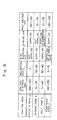
More specifically, according to a prior art two-tone
coating method, as shown in the block diagram of Fig. 35, an
upper half of a vehicle body is coated with a first color, for
example, by the use of paint of color A (Step1), a clear paint
is coated on the surface of the coating of color A (Step 2),
and the vehicle body is put in a baking furnace to cure the
coated films (Step 3). In the next place, masking tapes are
put on the vehicle body along borders of the coated area,
masking the coated area of color A to prevent deposition of a
second color, namely, to prevent deposition of paint of color
B on the color A area (Step 4). After masking the color A
area, the color B is coated on the lower half of the vehicle
body in such a way as that upper portions of the color B area
partly overlaps the color A area (Step 5). A clear paint is
then coated on the coated color A (Step 6), and the vehicle
body is put in the baking furnace again to cure the coated
films (Step 7), followed by removal of the masking tapes (Step
8). The removal of masking tapes reveals two coated areas of
different colors (two tones) which are clearly separated from
each other by a border line.
In the case of the above-described two-tone coating
method, however, coated films of the second color B are
forcibly stripped off together with the masking tapes at the
time of removal of the latter, leaving a stepped surface along
border lines between the color A and color B areas. In
addition, upon peeling off masking tapes, fine sawtooth-like
notches appear continuously along bordering edges of the color
B area to degrade the quality of finish coating to a
considerable degree.
The masking involves the jobs of sticking masking tapes
and sheet on and over a masking area and peeling off the
masking tapes and sheets afterwards. Because of the
difficulty of performing these jobs by automation, it has been
the usual practice to rely on manual labors in masking and
unmasking particular coating areas despite a conspicuous drop
in production efficiency.
Further, in the case of the two-tone coating method using
masking tapes, it is a paramount requisite to bake and cure
the coating films of the color A area into a dried state
before adhering masking tapes on the surfaces of the color A
or of the clear paint. For this purpose, the coating process
should include a step of coating a color paint, a step for
coating clear paint and a steps of baking coating films
separately for each one of the colors A and B, which is
obviously disadvantageous in view of degradations in
productivity and increases in production cost.
In an attempt to improve the productivity of the two-tone
coating process by aborting the masking step or by aborting
the use of masking tapes, there have been developed a number
of coating methods as disclosed, for example, in Laid-Open
Japanese Patent No. S58-58168 and Laid-Open Japanese Patent
No. H11-57606.
Firstly, above-mentioned Laid-Open Japanese Patent No.
S58-58168 discloses a method for coating heavy anti-rust or
corrosion-proof paint, (hereinafter referred to simply as "the
first prior art" for brevity), by the use of a coating robot
having a sprayer unit and a masking device in the form of a
masking plate on a fore distal end portion of a robot arm.
According to this coating method, a fore end portion of the
masking plate is abutted against a vehicle body at the time of
a heavy anti-rust coating operation thereby to cover the
vehicle body on the upper side of the masking plate. In this
state, lower portions of the vehicle body is coated with a
heavy corrosion-proof paint which is sprayed from the sprayer
unit.
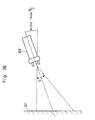
On the other hand, disclosed in above-mentioned Laid-Open
Japanese Patent No. H11-57606 (hereinafter referred to simply
as "the second prior art" for brevity) is a two-tone coating
method employing, for the purpose of demarcating a border line
on a work object 101, a sprayer unit which employs a binary
fluid nozzle spray gun (or the so-called air brush gun) 102
with straight directionability, namely, with a narrow spray
pattern which is smaller than 30 degrees in diverging angle
as shown in Fig. 36. An air gun (not shown) is located over
the spray gun 102 thereby to spurt air toward a border line of
a coating area. In addition, according to the coating method
of the second prior art, the spray gun 102 is tilted with
respect to a work object 101 by an angle which is greater than
half the diverging angle 6 of the spray pattern (> ½).
Namely, a border line of a coating area is demarcated on the
work object 101 by spraying paint from the spray gun 102 in
the tilted position. During a coating operation, air is
spurted toward the border line from the air gun to prevent
deposition, for example, of a color B paint on an adjoining
coating area which was coated with a color A paint in a
preceding stage.
In the case of the coating method according to the first
prior art, that is, in the case of the coating method
according to Laid-Open Japanese Patent No. S58-58168, the
masking plate is adapted to cover surface areas other than a
target coating area. Therefore, a large amount of paint
inevitably deposits on the masking plate during a coating
operation, necessitating to provide a paint scraper in
association with the masking plate thereby to scrape deposited
paint off and as a consequence requiring larger and complicate
equipments. Besides, the fore end of the masking plate which
is held in abutting engagement with a vehicle body during a
coating operation always has possibilities of damaging or
bruising coating surfaces. For this reason, the coating
method according to the first prior art may be applicable to
undercoatings like heavy anti-corrosive coatings which would
not require a quality finish, but does not suit for
application to finish coatings.
Further, in the case of the coating method according to
the above-mentioned second prior art, disclosed in Laid-Open
Japanese Patent No. H11-57606, a binary fluid nozzle spray gun
102 (an air brush gun) is employed as a sprayer unit for
demarcating a border line. The spray gun 102 of this sort is
adapted to spurt paint under the pressure of jet air. That
is, paint is vigorously spurted out from the spray gun 102
together with jet air. Therefore, there always a problem
that, while demarcating a border line by the use of a color B
paint, splashes of color B paint particles rebounding on the
surfaces of the work object 101 tend to scatter around and
deposit on surfaces of the coating film in the adjoining color
A area.
Further, according to the coating method of the above-mentioned
second prior art, air is spurted toward the position
of the border line from an air gun. A problem with an air gun
of this sort is that, because of the difficulty of controlling
the direction of air jet precisely toward an aimed position,
the spray of paint from the spray gun 102 is often blown off
and broken up by air jets, resulting in disturbances of the
border line.
Furthermore, generally the binary fluid nozzle spray gun
102 has been used as a brush in artistic work, for example,
for spraying a color on a painting, poster or craft work. In
addition, the binary fluid nozzle spray gun 102 is suited for
spraying a relatively small amount of a low viscosity dye
color or a laquer type paint, and low in capacity of atomizing
paint which is used for coating vehicle bodies or the like.
Namely, the binary fluid nozzle spray gun 102 is suited for
drawing a thin line by means of a small spray pattern, but not
suited for coating broad surface areas of a vehicle body or
the like. Even if used for coating vehicle bodies, it would
take a considerably long coating time and fail to yield high
quality finish coatings.
DISCLOSURE OF THE INVENTION
In view of the above-discussed problems with the prior
art, it is an object of the present invention to provide a
method for coating a work object in two tones, which can paint
a border line in a clearly defined form to distinguish one
coating area from an adjacent coating area of a different
color, while permitting to reduce the number of steps for a
two-tone coating operation, improve the reliability of
operation, and cut the cost of two-tone coating operations.
According to the present invention, in order to achieve
the above-stated objectives, there is provided a method for
coating a work object in two tones, comprising: [A] a first
color coating stage for coating a first color area on a
coating surface of said work object with first color paint;
[B] a border zone coating stage for coating a border zone with
second color paint, by (1) positioning a rotary atomizing head
of a sprayer unit at a close distance to said work object and
in an inclined state tilted toward said border zone, (2)
supplying mist blocking air in a direction forward of said
rotary atomizing head to block mist of said second color paint
from scattering and flying toward a first color coating on
said first color area, (3) without supplying shaping air to
shape a spray pattern, (4) applying no high voltage or
applying a high voltage of low level to paint if necessary,
and (5) coating a border zone with said second color paint to
paint a border line bounding on said first color area; and [C]
a belt zone coating stage for coating a belt zone with said
second color paint, by (1) positioning a rotary atomizing head
of a sprayer unit at a close distance to said work object and
in an inclined state tilted toward belt zone, (2) supplying
mist blocking air in a direction forward of said rotary
atomizing head to block mist of said second color paint from
scattering and flying toward a first color coating on said
first color area, (3) applying no high voltage or applying a
high voltage of low level to paint if necessary, and (4)
coating said second color paint on said belt zone continuously
from said border zone coating on said border zone by putting
said rotary atomizing head in reciprocating movements.
In the case of the arrangements just described above, in
the first color area coating stage, first color paint is
applied on a coating surface of a work object to form a first
color coating thereon.
In the next border zone coating stage, the rotary
atomizing head which is located at a close distance to the
work object is tilted toward the border zone on the coating
surface, while mist blocking air is supplied forward of the
rotary atomizing head to prevent mist, i.e., fine particles of
second color paint, from scattering and flying toward the
first color coating. In this stage, no shaping air is
supplied to shape the spray pattern. A high voltage is not
applied to the paint or a high voltage of a suppressed level
is applied, if desired, and paint is sprayed by high speed
rotation of the rotary atomizing head.
Accordingly, the second color paint is pulled toward a
negative pressure region which is formed forward of the rotary
atomizing head by high speed rotation of the latter, and at
the same time urged to fly radially outward under the
influence of centrifugal force. In this case, however, since
the rotary atomizing head is positioned at a close distance
from a work object, second color paint is allowed to reach and
deposit on the work object before it is atomized and scattered
around by pneumatic resistance. Therefore, a clear border
line can be painted on the work object. Besides, since the
rotary atomizing head is tilted with respect to a coating
surface of the work object, second color paint can be sprayed
solely by centrifugal force without resorting to jet air, so
that paint particles are allowed to deposit and settle on a
coating surface without scattering and rebounding off the
coating surface. In addition, the mist blocking air which is
supplied forward of the rotary atomizing head blocks paint
particles from scattering and flying toward the first color
coating, ensuring to finish the coating in favorable
conditions.
In the next belt zone coating stage, the rotary atomizing
head which is located at a close distance from the work object
is tilted toward the belt zone on the coating surface, while
mist blocking air is supplied in a direction forward of the
rotary atomizing head. In this stage, either a high voltage
is not applied or a high voltage of a suppressed level is
applied if necessary, while coating a wide belt zone (belt-like
surface area) on the coating surface of the work object
with second color paint continuously from the border line by
the rotary atomizing head which is put in reciprocating
movements.
As a consequence, scattering of paint particles is
blocked substantially in the same manner as in the above-described
border zone coating stage as second color paint is
coated on the work object continuously under the border zone
coating. At this time, since the rotary atomizing head is put
in reciprocating movements, second color paint can be coated
over a wide surface area of the work object continuously from
the border zone coating.
According to the present invention, there is also
provided a method for coating a work object in two tones,
which comprises: [A] a first color coating stage for coating a
first color area on a coating surface of said work object with
first color paint; [B] a border zone coating stage for coating
a border zone with second color paint, by (1) positioning a
rotary atomizing head of a sprayer unit at a close distance to
said work object and in an inclined state tilted toward said
border zone, (2) supplying mist blocking air in a direction
forward of said rotary atomizing head to block mist of said
second color paint from scattering and flying toward a first
color coating formed on said first color area, (3) without
supplying shaping air to shape a spray pattern, (4) applying
no high voltage or applying a high voltage of low level to
paint if necessary, and (5) coating a border zone with said
second color paint to paint a border line bounding on said
first color area; [C] a belt zone coating stage for coating a
belt zone with said second color paint, by (1) positioning a
rotary atomizing head of a sprayer unit at a close distance to
said work object and in an inclined state tilted toward said
belt zone, (2) supplying mist blocking air in a direction
forward of said rotary atomizing head to block mist of said
second color paint from scattering and flying toward a first
color coating on said first color area, (3) applying no high
voltage or applying a high voltage of a suppressed level to
paint if necessary, and (4) coating said second color paint on
said belt zone continuously from said border zone coating on
said border zone by putting said rotary atomizing head in
reciprocating movements; and [D] a remainder area coating
stage for coating said second color paint on remainder areas
of said work object left subsequent to said belt zone coating
stage.
In this instance, in the first color area coating stage,
first color paint is applied on a coating surface of a work
object to form a first color coating thereon.
In the next border zone coating stage, the rotary
atomizing head which is located at a close distance to the
work object is tilted toward the border zone on the coating
surface, while mist blocking air is supplied forward of the
rotary atomizing head to prevent mist, i.e., fine particles of
second color paint, from scattering and flying toward the
first color coating. In this stage, no shaping air is
supplied to shape the spray pattern. A high voltage is not
applied to the paint or a high voltage of a suppressed level
is applied, if desired, and paint is sprayed by high speed
rotation of the rotary atomizing head.
Accordingly, second color paint is pulled toward a
negative pressure region which is formed forward of the rotary
atomizing head by high speed rotation of the latter, and at
the same time urged to fly radially outward under the
influence of centrifugal force. In this case, however, since
the rotary atomizing head is positioned at a close distance
from a work object, second color paint is allowed to reach and
deposit on the work object before it is atomized and scattered
around by pneumatic resistance. Therefore, a clear border
line can be painted on the work object. Besides, since the
rotary atomizing head is tilted with respect to a coating
surface of the work object, second color paint can be sprayed
solely by centrifugal force without resorting to jet air, so
that paint particles are allowed to deposit and settle on a
coating surface without scattering and rebounding off the
coating surface. In addition, the mist blocking air which is
supplied forward of the rotary atomizing head blocks paint
particles from scattering and flying toward the first color
coating, ensuring to finish the coating in favorable
conditions.
In the next belt zone coating stage, the rotary atomizing
head which is located at a close distance from the work object
is tilted toward the belt zone on the coating surface, while
mist blocking air is supplied in a direction forward of the
rotary atomizing head. In this stage, either a high voltage
is not applied or a high voltage of a suppressed level is
applied if necessary, while coating a wide belt zone on the
coating surface of the work object with second color paint
continuously from the border line by the rotary atomizing head
which is put in reciprocating movements.
As a consequence, scattering of paint particles is
suppressed substantially in the same manner as in the above-described
border zone coating stage as second color paint is
coated on the work object continuously under the border zone
coating. Further, a broad belt zone (a belt-like area) is
coated by reciprocating movements of the rotary atomizing head
in the belt zone coating stage, so that, in coating second
color paint in the succeeding remainder area coating stage,
the rotary atomizing head can be located at a large distance
from the first color coating to prevent particles of second
color paint from depositing on the first color coating.
In the remainder area coating stage, second color paint
is coated on remaining areas of the coating surface
continuously from the belt zone coating. At this time, the
border zone coating and the belt zone coating of second color
paint intervene between the first color coating and the
remainder areas to be painted in the remainder area coating
stage, so that particles of second color paint can be
prevented from scattering and flying toward the first color
coating even under normal coating conditions.
According to the present invention, coating is formed on
the work object in the border zone coating stage, by (1)
reducing a coating distance between a confronting marginal
edge of the rotary atomizing head and the work object to a
minimal value when the rotary atomizing head is in a coating
position for painting the border line bounding on a first
color coating on the first color coating area, and (2)
increasing the coating distance between the marginal edge of
the rotary atomizing head and the work object when the rotary
atomizing head is moved in a direction away from the border
line, (3) while reciprocating the rotary atomizing head toward
and away from the border line in a direction of intersecting
the latter.
In this instance, in relation with reciprocating coating
action, marginal edge of the rotary atomizing head is
positioned closer to a coating surface on the side of a border
line bounding on the first color coating, thereby to form the
border line with thick and clear coating. On the other hand,
when in a position away from the first color coating and the
border line, the rotary atomizing head is located at a greater
distance from the work object to spray paint particles over a
broader area. Accordingly, flat and thinner coating is formed
on a surface area distant from the border line.
According to the present invention, the rotary atomizing
head is moved substantially parallel with the border line
while painting a border zone area in the border zone coating
stage.
In this case, by moving the rotary atomizing head
parallel with the border line, a smooth (rectilinear) border
line can be painted on the surface of the work object.
According to the present invention, coating is applied on
a surface area of the work object in the belt zone coating
stage, by (1) reducing a coating distance between a
confronting marginal edge of the rotary atomizing head and
work object to a minimal value on the side of a border zone
coating, (2) increasing the coating distance between the
marginal edge of the rotary atomizing head and the work object
when the rotary atomizing head is moved in a direction away
from the border zone coating, (3) while reciprocating the
rotary atomizing head toward and away from the border line in
a direction of intersecting the latter.
In this instance, at a position on the side of the border
zone coating, the coating distance between an opposing
marginal edge of the rotary atomizing head and a coating
surface is reduced to a minimum value to prevent particles of
second color paint from depositing on the first color coating
across the border zone coating. Besides, at the time of
forming second color coating continuously under the belt zone
coating, flat and thinner coating can be formed in overlapping
portions of second color paint, namely, on surface areas away
from the border line.
According to the present invention, the rotary atomizing
head is moved substantially parallel with the border line
while painting the belt zone in the belt zone coating stage.
In this instance, second color paint which is sprayed by
the rotary atomizing head is coated on substantially parallel
with the border line, and particles of second color paint are
prevented from flying toward the first color coating across
the border zone coating and the belt zone coating.
According to the present invention, in the belt zone
coating stage, shaping air is either not supplied at all or
supplied in a suppressed amount which will not disturb the
mist blocking air.
In this instance, second color paint which is sprayed
from the rotary atomizing head by centrifugal force is allowed
to deposit on the work object free of possibilities of
disturbance by shaping air, and particles of second color
paint are prevented from flying toward and depositing on the
first color coating.
According to the present invention, the rotary atomizing
head of the sprayer unit is provided with an air nozzle
adapted to spurt mist blocking air in a direction forward of
the rotary atomizing head, the air nozzle being turned on to
supply mist blocking air forward of the rotary atomizing head
in the border zone coating stage and the belt zone coating
stage.
In this instance, when mist blocking air is supplied in a
direction forward of the rotary atomizing head, the mist
blocking air prevents particles of second color paint from
flying toward and depositing on the first color coating.
According to the present invention, the rotary atomizing
head of the sprayer unit is provided with an air nozzle
adapted to spurt mist blocking air in a forward direction
toward the rotary atomizing head and a flow rectification
plate for guiding mist blocking air from the air nozzle in a
direction forward of the rotary atomizing head, the air nozzle
being turned on to spurt out mist blocking air and supply same
forward of the rotary atomizing head under the guidance of the
flow rectification plate in the border zone coating stage and
the belt zone coating stage.
In this instance, the mist blocking air which is supplied
from the air nozzle toward the rotary atomizing head is hit on
the flow rectification plate and thereby turned toward the
rotary atomizing head. By the mist blocking air which is
controlled by the flow rectification plate, particles of
second color paint are prevented from flying toward the first
color coating across the border line in a reliable manner.
According to the present invention, in the border zone
coating stage and the belt zone coating stage, the rotary
atomizing head is tilted through an angle in the range between
50 degrees and 80 degrees with respect a straight line normal
to a coating surface of the work object.
In this instance, paint particles which are sprayed by
the rotary atomizing head under the influence of centrifugal
force are allowed to deposit and settle on a coating surface
of the work object without scattering in the direction of the
first color coating.
According to the present invention, there is also
provided a method for coating a work object in two tones,
which comprises: [A] a first color coating stage for coating a
first color area on a coating surface of said work object with
first color paint; [B] a bordering belt zone coating stage for
coating a bordering belt zone with second color paint, by (1)
positioning a rotary atomizing head of a sprayer unit at a
close distance to said work object and in an inclined state
tilted toward said bordering belt zone, (2) supplying mist
blocking air in a direction forward of said rotary atomizing
head to block mist of said second color paint from scattering
and flying toward a first color coating on said first color
area, (3) without supplying shaping air to shape a spray
pattern, (4) applying no high voltage or applying a high
voltage of a suppressed level to paint if necessary, and (5)
coating said bordering belt zone with said second color paint
to paint a border line bounding on said first color area by
putting said rotary atomizing head in reciprocating movements;
and [C] a remainder area coating stage for coating said second
color paint on remainder area of said work object subsequent
to said bordering belt zone coating stage.
In this instance, in the first color area coating stage,
first color paint is applied on a coating surface of a work
object to form a first color coating thereon.
In the next bordering belt zone coating stage, the rotary
atomizing head which is located at a close distance from the
work object is tilted toward a bordering belt zone on the
coating surface, while mist blocking air is supplied forward
of the rotary atomizing head to prevent mist, i.e., fine
particles of second color paint, from scattering and flying
toward the first color coating. In this stage, no shaping air
is supplied to shape the spray pattern. A high voltage is not
applied to the paint or a high voltage of a suppressed level
is applied, if desired, and paint is sprayed by high speed
rotation of the rotary atomizing head.
Accordingly, the second color paint is pulled toward a
negative pressure region which is formed forward of the rotary
atomizing head by high speed rotation of the latter, and at
the same time urged to fly radially outward under the
influence of centrifugal force. In this case, however, since
the rotary atomizing head is positioned at a close distance
from a work object, second color paint is allowed to reach and
deposit on the work object before it is atomized and scattered
around by pneumatic resistance. Therefore, a clear border
line can be painted on the work object. Besides, since the
rotary atomizing head is tilted with respect to a coating
surface of the work object, second color paint can be sprayed
solely by centrifugal force without resorting to jet air, so
that paint particles are allowed to deposit and settle on a
coating surface without scattering and rebounding off the
coating surface. In addition, the mist blocking air which is
supplied forward of the rotary atomizing head blocks paint
particles from scattering and flying toward the first color
coating, ensuring to finish the coating in favorable
conditions.
In the remainder area coating stage, remainder areas of
the coating surface on the work object are coated with second
color paint continuously from the bordering belt zone. At
this time, the broad bordering belt zone coating of second
color paint intervenes between the first color coating and the
remainder surface areas to be painted in the remainder area
coating stage, so that particles of second color paint can be
prevented from scattering and flying toward the first color
coating even under normal coating conditions.
According to the present invention, a coating is applied
in the bordering belt zone coating stage, by (1) reducing a
coating distance between a confronting marginal edge of the
rotary atomizing head and the work object to a minimal value
when the rotary atomizing head is in a coating position for
painting the border line bounding on a first color coating on
the first color coating area, and (2) increasing the coating
distance between the marginal edge of the rotary atomizing
head and the work object when the rotary atomizing head is
moved in a direction away from the border line, (3) while
reciprocating the rotary atomizing head toward and away from
the border line in a direction of intersecting the latter.
In this instance, in relation with reciprocating coating
action, marginal edge of the rotary atomizing head is
positioned closer to a coating surface on the side of a border
line bounding on the first color coating, thereby to form the
border line with thick and clear coating. On the other hand,
when in a position away from the first color coating and the
border line, the rotary atomizing head is located at a greater
distance from the work object to spray paint particles over a
broader area. Accordingly, flat and thinner coating is formed
on a surface area distant from the border line.
According to the present invention, the rotary atomizing
head is moved substantially parallel with the border line
while painting a border zone area in the bordering belt zone
coating stage.
In this instance, by moving the rotary atomizing head
parallel with the border line, a smooth (rectilinear) border
line can be painted on the surface of the work object.
According to the present invention, the rotary atomizing
head of the sprayer unit is provided with an air nozzle
adapted to spurt mist blocking air in a direction forward of
the rotary atomizing head, the air nozzle being turned on to
supply mist blocking air forward of the rotary atomizing head
in the bordering belt zone coating stage.
According to the present invention, the rotary atomizing
head of the sprayer unit is provided with an air nozzle
adapted to spurt mist blocking air in a forward direction
toward the rotary atomizing head and a flow rectification
plate for guiding mist blocking air from the air nozzle in a
direction forward of the rotary atomizing head, the air nozzle
being turned on to spurt out mist blocking air and supply same
forward of the rotary atomizing head under the guidance of the
flow rectification plate in the bordering belt zone coating
stage.
According to the present invention, in the bordering belt
zone coating stage, the rotary atomizing head is tilted
through an angle in the range between 50 degrees and 80
degrees with respect a straight line normal to a coating
surface of the work object.
In this instance, paint particles which are sprayed by
the rotary atomizing head under the influence of centrifugal
force are allowed to deposit and settle on a coating surface
of the work object without scattering in the direction of the
first color coating.
According to the present invention, the coating method
further comprises a baking stage for baking coatings of the
first and second color paint simultaneously after completing
coating operations of the respective coating stages.
In this instance, after coating first color paint, second
color paint is coated on before baking and curing first color
coating into a dried state, namely, when first color coating
is still in a wet state, by the so-called wet-on-wet process.
Therefore, it becomes possible to omit a baking stage
subsequent to a first color area coating stage, which is
inevitably required in the above-described prior art for
masking purposes, and thus to simplify the coating process.
BRIEF DESCRIPTION OF THE DRAWINGS
In the accompanying drawings:
BEST MODE FOR CARRYING OUT THE INVENTION
Hereafter, the two-tone coating method according to the
present invention is described more particularly by its
preferred embodiments which are applied by way of example to
two-tone coating of a vehicle body, a typical work object to
which the present invention is applicable.
Referring first to Figs. 1 through 23, there is shown a
first embodiment of the two-tone coating method according to
the present invention, using sprayer units and coating
equipments as described below.
Indicated at 1 is a coating plant with a coating line
which is arranged to coat a vehicle body 12 in two colors (in
two tones), i.e., with a first color or color A paint and a
second color or color B paint. More specifically, a conveyer
11 is provided in the coating plant 1 to transfer a vehicle
body through a color A area coating stage 2, a border zone
coating stage 3, a belt zone coating stage 4, a remainder area
coating stage 5, a clear paint coating stage 6 and a baking
stage 7, which are provided along the coating line from the
upstream to downstream side of the conveyer 11.
In the initial color A area coating stage 2, the color A
paint is coated on an upper half of the vehicle body 12,
including the entire exterior surfaces of the bonnet 12A and
roof 12B and upper half portions of left front door 12C, left
rear door 12D, right front door, right rear door (both not
shown in the drawings), and a back door 12E.
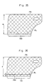
Here, the two-tone coating method of the present
embodiment is explained by way of the left rear door 12D shown
in Fig. 17. Namely, in the initial color A area coating stage
2, a color A area a of the vehicle door 12D is coated with the
color A paint. In the next border zone coating stage 3, as
shown in Fig. 18, a border line BL is painted on a border zone
b horizontally across the door by coating the color B paint
which is different in color or shade from the color A paint,
in overlapping relation with lower portions of the color A
coating PA which was painted in the preceding color A area
coating stage2. In the succeeding belt zone coating stage 4,
as shown in Fig. 22, a relatively wide coating (a belt-like
coating) is formed on a belt zone c by the use of the color B
paint, continuously on the lower side of the border zone
coating PB1 on the vehicle body 12. In the next remainder
area coating stage 5, as shown in Fig. 23, the color B paint
is coated on remainder portions of the surfaces of the vehicle
body 12 which were not coated in the preceding color A area
coating stage 2, border zone coating stage 3 or belt zone
coating stage 4. Namely, in the remainder area coating stage
5, the color B paint is coated on remainder areas d on the
lower side of a belt zone coating PB2 on the belt zone c to
form a remainder area coating PB3.
In the next clear paint coating stage 6, a clear paint is
coated on the coating films which were formed in the preceding
color A area coating stage 2, border zone coating stage 3,
belt zone coating stage 4 and remainder area coating stage 5.
Then, in the final baking stage 7, the vehicle body 12 is put
in a baking furnace (not shown) to cure and set simultaneously
all of coating films of the color A paint, color B paint and
clear paint which were applied in the preceding coating
stages.
In this instance, as shown in Fig. 2, tracking apparatus
13 and 14, coating robots 15 and 16 and rotary atomizing head
type sprayer units 21, 31, 41 or 51 are provided in the color
A area coating stage 2, border zone coating stage 3, belt zone
coating stage 4, remainder area coating stage 6 and clear
paint coating stage 6, as will be described in greater detail
hereinafter.
As a vehicle body 12 is passed successively through the
respective stages 2 to 5, it is painted in two tones in the
same manner as exemplified by way of the left rear door 12D
shown in Fig. 3, having a color A coating PA and a color B
coating PB in its upper and lower half portions on the
opposite sides of a border line BL, respectively.
On the other hand, indicated at 11 are a pair of work
transfer conveyers (Fig. 2) which are provided in the coating
plant. These conveyers 11 are arranged to run through the
color A area coating stage 2, border zone coating stage 3,
belt zone coating stage 4, remainder area coating stage 5 and
clear paint coating stage 6. Further, a support table 11A is
provided on the conveyers 11 to support thereon a vehicle body
12 and transfer same continuously or intermittently forward
within the coating plant 1, as described below.
Indicated at 12 is the vehicle body which is mounted on
the support table 11A as a work object to be coated. The
vehicle body 12 is largely constituted by a bonnet 12A, roof
12B, left front door 12C, left rear door 12D, right front
door, right rear door (both of the doors on the right side are
not shown in the drawings), and a back door 12E.
Indicated at 13 is a tracking apparatus which is located
in the color A area coating stage 2 on the left side of the
path of transfer of the conveyers 11. Indicated at 14 is a
tracking apparatus which is also located in the color A area
coating stage 2 on the right side of the path of transfer of
the conveyers 11. In this instance, the tracking apparatus 13
and 14 are largely constituted by tracking rails 13A and 14A
which are extended in parallel relation with the conveyers 11,
and carriages 13B and 14B which are movable on and along the
tracking rails 13A and 14A, respectively. Mounted on the
carriages 13B and 14B are coating robots 15 and 16 which will
be described below. By the tracking apparatus 13 and 14,
coating robots 15 and 16 are movable in the forward or reverse
direction in step with the vehicle body 12 which is
transferred by the conveyers 11.
Indicated at 15 is the coating robot which is mounted on
the carriage 13B of the tracking apparatus 13 on the left
side. This coating robot 15 is largely constituted by a
rotary base 15A which is rotatably supported on the carriage
13B, a vertical arm 15B which is pivotally supported on the
rotary base 15A, and a horizontal arm 15C which is pivotally
connected to an upper end portion of the vertical arm 15B, and
a wrist 15D is attached to the fore distal end of the
horizontal arm 15C.
Further, indicated at 16 is the coating robot which is
mounted on the carriage 14B of the tracking apparatus 14 on
the right side. Similarly to the above-described coating
robot 15, this coating robot 16 is largely constituted by a
rotary base (not shown), a vertical arm 16B, a horizontal arm
16C and a wrist (not shown).
Though not shown in the drawings, similar tracking
apparatus and coating robots (not shown) are also provided in
each one of the above-mentioned border zone coating stage 3,
belt zone coating stage 4, remainder area coating stage 5 and
clear paint coating stage 6.
Furthermore, in the coating stages 2 to 6 which require
to apply paint under different conditions, a plural number of
rotary atomizing head type sprayer units 21, 31, 41 and 51 are
selectively used. These sprayer units 21, 31, 41 and 51 are
arranged differently depending upon required coating
conditions, for example, in angle of inclination with respect
to a coating surface of the vehicle body 12, coating distance
between the vehicle body 12 and an opposing marginal edge 23A,
33A, 43A or 53A of the rotary atomizing head 23, 33, 43 or 53,
presence or absence of shaping air, presence or absence of
mist blocking air, and conditions of high voltage application
(whether or not a high voltage is applied or the what level of
high voltage is to be applied).
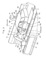
In this regard, the rotary atomizing head type sprayer
unit 21 which is used in the color A area coating stage 2 is
arranged in the manner as follows. As shown in Fig. 4, the
sprayer unit 21 is constituted by an assembly of a cylindrical
casing 22 which is attached to the wrist 15D of the coating
robot 15 at its base end and bent angularly in its
intermediate portion, and a rotary atomizing head 23 which is
provided rotatably at the fore end of the casing 22. The
rotary atomizing head 23 is mounted on a rotational shaft of
an air motor (not shown) which is built into the casing 22,
and thereby put in high speed rotation. Further, extended
internally through the casing 22 is a feed tube (not shown)
which has its base end connected to a paint supply source and
a fore end opened toward the rotary atomizing head 23 to
supply paint thereto.
Furthermore, provided at the fore end of the casing 22
and around the rotary atomizing head 23 are a multitude of
shaping air outlet holes (not shown) to spurt out shaping air
therethrough for shaping the spray pattern. Through the feed
tube, the sprayer unit 21 can apply a high voltage to paint to
be supplied to the rotary atomizing head, for example, a high
voltage in the range of -30 to -120 kv to deposit paint
efficiently on the vehicle body 12 which is connected to
earth.
In this instance, the rotary atomizing head type sprayer
unit 21 which is used in the color A area coating stage 2 is
positioned in such a way that the rotational center axis O-O
of the rotary atomizing head 23 is disposed substantially at
right angles (at an inclination angle α1 of 0 degree) with
respect to a coating surface of the vehicle body 12. While
the rotary atomizing head type sprayer unit 21 in that
position is moved correspondingly to the surface contour of
the vehicle body 12, the color A paint coating PA is formed on
the vehicle body 12. At this time, as shown in Figs. 4 and
15, the distance L1 between the coating surface of the vehicle
body 12 and an opposing marginal edge 23A of the rotary
atomizing head 23 is maintained in the range of 200 mm to 350
mm, and the paint is applied with a high voltage of from -30
kv to -120 kv. Further, for shaping the spray pattern,
shaping air is spurted out through the shaping air outlet
holes toward paint particles which are sprayed by the rotary
atomizing head 23. In this case, an air nozzle and a flow
rectification plate which supply mist blocking air in a
direction forward of the rotary atomizing head 23 are not
provided on the rotary atomizing head type sprayer unit 21
which is used in the color A area coating stage 2.
Turning now to Fig. 5, there is shown the rotary
atomizing head type sprayer unit 31 which is located on the
downstream side of the color A area coating stage 2 for use in
the next border zone coating stage 3. Similarly to the
sprayer unit 21 for the color A area coating stage 2, the
sprayer unit 31 is constituted by an assembly of a
cylindrical casing 32 which is bent into an angular form, and
a rotary atomizing head 33 which is provided at the fore end
of the casing 32. Further, the sprayer unit 31 is provided
with an air motor and a feed tube, which are not shown in the
drawings, and can apply a high voltage to the paint.
However, the sprayer unit 31 for use in the border zone
coating stage 3 differs from the sprayer unit 21 in the color
A area coating stage 2 in that an air nozzle 35 is provided at
a distal end portion of a stay 34, which is extended out from
the casing 32, along with a rectification plate 36 which is
provided on a fore end portion of the casing 32 and forward of
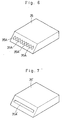
the air nozzle 35. As shown in Fig. 6, the air nozzle 35 is
provided with a plural number of air outlet holes 35A which
are arranged in a row and opened toward the fore end of the
sprayer unit 31. In this connection, there may be employed an
air nozzle 35' which is provided with an air outlet hole 35A'
as exemplified in Fig. 7. By mist blocking air which is
spurted forward from the air outlet holes 35A of the air
nozzle 35, particles of the color B paint which is sprayed
from the rotary atomizing head 33 are prevented from flying or
scattering toward and depositing on the color A coating PA
which was applied in the preceding color A area coating stage
2.
Further, by the flow rectification plate 36 which is
provided on a fore end portion of the casing 22 as mentioned
above, mist blocking air which is supplied from the air nozzle
35 is guided to flow along a coating surface and directed
toward the center of the sprayer unit 31, namely, toward the
rotary atomizing head 33. Therefore, mist (minute particles)
of the color B paint is effectively prevented from flying and
scattering in the direction of the color A coating PA.
In the case of the rotary atomizing head type sprayer
unit 31 which is used in the border zone coating stage 3, the
rotational center axis O-O of the rotary atomizing head 33 is
tilted downward (toward the border zone b) with respect to a
straight line which perpendicularly intersects the coating
surface of the vehicle body, by a predetermined inclination
angle α2 in the range between 50 degrees and 80 degrees, for
example, by approximately 70 degrees. In this instance, as
shown in Figs. 5 and 15, the distance L2 between the coating
surface of the vehicle body 12 and the opposing marginal edge
33A of the rotary atomizing head 33 is set at a value in the
range of 5 mm to 20 mm, for example, set at approximately 10
mm when in a position for coating the border line BL. When in
a position on the lower side of the border line BL as
indicated by a two-dot chain line, the rotary atomizing head
33 is located at a greater distance L2' which is greater than
L2. Further, mist blocking air is supplied in a direction
forward of the rotary atomizing head 33 by the air nozzle 35.
In this border zone coating stage 3, no shaping air is used,
and no high voltage or a high voltage approximately as low as
-10 kv is applied if necessary.
Advantages accruing from the downward inclination of the
rotary atomizing head 33 toward the border zone b and from the
location of the rotary atomizing head 33 in the proximity of a
vehicle body are explained below with reference to Figs. 8 to
11.
Firstly, as the rotary atomizing head 33 is put in high
speed rotation, it gives rise to strong air streams around and
in radial directions of the rotary atomizing head 33. As a
result, a negative pressure region 37 is formed forward of the
rotary atomizing head 33. Therefore, as shown in Fig. 8,
paint particles which are released from the marginal edge 33A
of the rotary atomizing head 33 tend to fly in radially
outward directions under the influence of centrifugal force
resulting from high speed rotation of the rotary atomizing
head 33. However, released paint particles are pulled toward
the negative pressure region 37, and, after being turned in a
converging direction at a position approximately at a distance
of 10 mm from the marginal edge 33A of the rotary atomizing
head 33, caused to spread and fly in radially outward
directions under the influence of centrifugal force, pneumatic
resistance etc.
Therefore, in a case where the color B paint is sprayed
from the rotary atomizing head 33 which is positioned
substantially at right angles with respect to a coating
surface of the vehicle body 12 and from the marginal edge 33A
of the rotary atomizing head 33 which is positioned at a close
distance of about 10 mm from the vehicle body 12 as shown in
Fig. 9, the color B paint deposits on the vehicle body 12
conspicuously in a hollow pattern, forming a thicker ring-like
coating PB' on the outer side as shown in Figs. 9 and 10.
Therefore, if the sprayer unit 31 is moved relative to the
vehicle body 12 in this state a border zone coating BL1' is
painted on the vehicle body 12 with the color B paint, which
has a conspicuously greater thickness at upper and lower sides
of the border zone coating PB1' as shown in Fig. 11. This
means that it becomes difficult to form a coating of
satisfactory quality finish, which is uniform in coating film
thickness distribution, in a succeeding coating stage or
stages continuously from the border zone coating BL1'.
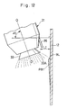
In contrast, according to the present embodiment of the
invention, as shown in Fig. 12, the sprayer unit 31 is tilted
downward by 70 degrees (with an inclination angle α2 = 70
degrees), and the marginal edge 33A of the rotary atomizing
head 33 is located at a close distance of about 10mm from the
coating surface of the vehicle body 12 (with a coating
distance L2 = 10mm). In this case, paint particles which are
released from the marginal edge 33A of the rotary atomizing
head 33 at a closer distance to the vehicle body 12 are mostly
allowed to deposit on the vehicle body 12, defining a clear
border line BL by way of a border zone coating PB1 which has a
sufficient thickness particularly at the position of the
border line BL. On the other hand, when in a position away
from the border line BL of the border zone coating PB1, the
rotary atomizing head 33 is located at a coating distance L2'
which is greater than the above-mentioned coating distance L2,
and therefore at this position paint particles are sprayed
over broader areas to form a thinner gradational coating film
which gradually fades out (in a hazy or foggy shade) in its
lower end portions. It follows that, when a belt zone coating
PB2 is formed continuously on a surface area on the lower side
of and in partly overlapping relation with the border zone
coating PB1, in a direction away from the border line BL, the
above arrangements make it possible to form a coating film of
thickness, preventing conspicuous increases in thickness
particularly in those areas where the belt zone coating PB2 is
overlapped on lower portions of the border zone coating PB1.
Further, the color B paint can be sprayed on a coating
surface of the vehicle body 12 solely under the influence of
centrifugal force of the rotary atomizing head 33 by setting
the coating distance L2 between the marginal edge 33A of the
rotary atomizing head 33 and the vehicle body 12 at a value of
10mm where paint particles are still in the form of a
converged flux with less scattering. Unlike paint particles
which are spurted out by the use of high pressure air jets,
particles of the color B paint which are sprayed by the rotary
atomizing head 33, without using air jets, can deposit
straight on the surface of the vehicle body 12 and settle
thereon to paint a clear border line BL, without rebounding on
the coating surface to scatter in random directions.
In this regard, it is to be understood that the above-mentioned
settings, including the angle of inclination α2 of
the rotary atomizing head 33 in the range of from 50 to 80
degrees and the coating distance L2 between the coating
surface of the vehicle body 12 and the marginal edge 33A of
the rotary atomizing head 33 in the range of 5mm to 20mm, can
be modified depending upon the outside diameter and rotational
speed of the rotary atomizing head 33, the type and feed rate
of paint or other conditions which influence the paint
atomization behaviors.
Further, as the coating distance L2 from the marginal
edge of the rotary atomizing head 33 to the coating surface of
the vehicle body 12 approaches 10mm, the flow rectification
plate 36 comes closer to the coating surface of the vehicle
body 12. Therefore, by the rectification plate 36, mist
blocking air which is supplied from the air nozzle 35 is
guided in a direction forward of the rotary atomizing head 33
in such a way as to target at the position of the border line
BL to form streams of mist blocking air effectively.
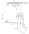
Nextly, a belt zone coating stage is located on the
downstream side of the border zone coating stage 3, and the
belt zone coating stage 4 is employing a rotary atomizing head
type sprayer unit 41 which is arranged in the manner as
described below with reference to Fig. 13. Similarly to the
sprayer unit 31 which is used in the border zone coating stage
3, the spryer unit 41 is constituted by an assembly of a
casing 42 and a rotary atomizing head 43, and provided with an
air motor, a feed tube and shaping air outlet holes, which are
not shown in the drawings, and can apply a high voltage to the
paint. Further, an air nozzle 45 is provided at a distal end
of a stay 44, and a flow rectification plate 46 is provided at
a fore distal end portion of the casing 42.
Furthermore, similarly to the sprayer unit 31 of the
border zone coating stage 3, the rotary atomizing head type
sprayer unit 41 of the belt zone coating stage 4 has its
rotary atomizing head 43 tilted downward (toward the belt zone
c) by an inclination angle α3 which is in the range of from 50
to 80 degrees, for example, approximately by 70 degrees. In
this instance, as shown in Figs. 13 and 15, the coating
distance L3 between the coating surface of the vehicle body 12
and the marginal edge 43A of the rotary atomizing head 43 is
in the range of from 5mm to 40mm, for example, set at
approximately 10mm on the side of the border zone coating PB1,
but increased to a greater distance L3' when in a position
which is spaced from the border zone coating PB1 in the
downward direction as indicated by two-dot chain line. In
this belt zone coating stage 4, mist blocking air is spurted
out from the air nozzle 45 in a direction forward of the
rotary atomizing head 43. In this stage, shaping air is not
used, or, if necessary, is used only in a small amount which
will not interfere with mist blocking air. Further, in this
stage, a high voltage is not applied, or, if necessary, is
applied only at a suppressed level of approximately -30kv.
In this instance, by spraying paint from the sprayer unit
41 which is inclined by 70 degrees in a downward direction or
toward the belt zone c, particles of the color B paint which
are sprayed solely by centrifugal force of the rotary
atomizing head 43 are allowed to deposit and settle down on
the coating surface to form a belt zone (band-like) coating
PB2 continuously on the lower side of the border zone coating
PB1, without trespassing the border zone coating PB1 by
rebounding on and scattering away from the coating surface.
Further, since the belt zone coating PB2 which is applied
in the belt zone coating stage 4 has nothing to do with the
formation of the border line BL, the rotary atomizing head can
be set at a greater coating distance L3 in the range of from
5mm to 40mm as compared with the coating distance L2 in the
border zone coating stage 3 which is in the range of from 5mm
to 20mm. It follows that the belt zone coating PB2 can be
applied over a broader area than the border zone coating PB1.
In forming a remainder area coating PB3 in the succeeding
remainder area coating stage 5 which will be described later,
particles of the color B paint are securely prevented from
flying across the belt zone coating PB2 and border zone
coating PB1 and depositing on the color A coating PA because
there is a large distance to the border line BL.
Furthermore, in the belt zone coating stage 4, shaping
air is not used, or, if necessary, it is used only in a
suppressed amount which will not interfere with mist blocking
air. Particles of the color B paint which are sprayed by
centrifugal force of the rotary atomizing head 43 deposit on
the work object without influenced by shaping air. Therefore,
particles of the color B paint are prevented from being
disturbed and scattered to deposit on the surface of color A
coating PA.
Nextly, a remainder area coating stage is located on the
downstream side of the belt zone coating stage 4, and the
remainder area coating stage 5 is employing a rotary atomizing
head type sprayer unit 51 which is arranged in the manner as
described below with reference to Fig. 14. Substantially
similarly to the sprayer unit 21 in the color A area coating
stage 2, this sprayer unit 51 is constituted by an assembly
including a casing 52, a rotary atomizing head 53, and
provided with an air motor, a feed tube and shaping air outlet
holes, which are not shown in the drawings, and is capable of
applying high voltage to paint. Further, an air nozzle 55 is
provided at a distal end of a stay 54, and a flow
rectification plate 56 is provided on a fore end portion of
the casing 52.
In the case of the rotary atomizing head type sprayer
unit 51 of the remainder area coating stage 5, an inclination
angle α4 of the rotary atomizing head 53 is set substantially
at zero degree. Therefore, even if the rotary atomizing head
53 is inclined slightly downward (toward a remainder area d),
its inclination angle remains in the range of 1 to 10 degrees,
for instance, at 2 degrees. Further, as shown in Figs. 14 and
15, a coating distance L4 between the vehicle body 12 and
marginal edge 53A of the rotary atomizing head 53 is set at a
value in the range of from 100mm to 350mm, for example, at
approximately 150mm. Mist blocking air is supplied from the
air nozzle at a suitable rate which is determined in relation
with the width of the belt zone coating PB2, kind of paint and
surface contour of the vehicle body 12. Further, similarly to
the color A area coating stage 2, shaping air is used and a
high voltage of -30kv to -120kv is applied to paint in the
remainder area coating stage 5.
In this remainder area coating stage 5: the sprayer unit
51 is tilted downward by approximately 2 degrees toward the
remainder area d to spray paint in an opposite direction away
from the color A coating PA; the coating distance L4 is set at
a value in the range of 100mm to 350mm to position the sprayer
unit at a smaller coating distance than the coating distance
L1 (between 200mm and 350mm) in the color A area coating stage
2; and the rotary atomizing head 53 is provided with the air
nozzle 55 and flow rectification plate 56 to spurt out mist
blocking air from the air nozzle 55 in a direction forward of
the rotary atomizing head 53 thereby to prevent particles of
the color B paint, which are sprayed by the rotary atomizing
head 53, from flying over the belt zone coating PB2 and border
zone coating PB1 and depositing on the surface of the color A
coating PA.
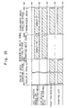
Having the arrangements as described above, the two-tone
coating apparatus according to the present embodiment of the
invention is advantageously used for a two-tone coating
operation in the manner as described below with reference to
the time chart of Fig. 16 and the various operational phases
illustrated in Figs. 17 through 23.
Firstly, as soon as a vehicle body 12 on a support table
11A of the conveyer 11 is delivered to the coating plant 1,
two-tone coating is started at the color A area coating stage
or a first color coating stage 2 by coating a color A area of
the vehicle body 12 with color A paint.
In the color A area coating stage, for example, an upper
half of the vehicle body 12 is coated with color A paint.
More specifically, as shown in Fig. 4, the robot arms 15B and
15C of the coating robot 15 in the color A area coating stage
are put in action to position the rotary atomizing head 23 of
the sprayer unit 21 substantially at right angles with respect
to the coating surface of the vehicle body 12. Besides, the
sprayer unit 21 is controlled to maintain a constant coating
distance L1 in the range of 200mm to 350mm, while supplying
shaping air to the sprayer unit and applying color A paint a
high voltage in the range of -30 to -120kv.
In this state, color A paint is supplied to the rotary
atomizing head 23 from the feed tube and sprayed toward the
vehicle body 12 by the rotary atomizing head 23. Whereupon,
as shown in Fig. 4, color A paint particles which are charged
with a high voltage deposit on the surface of the vehicle body
12 to form a color A coating PA thereon. At this time, by
means of the tracking apparatus 13 and coating robot 15, the
sprayer unit 21 is moved along and reciprocated up and down
across the upper half of the vehicle body 12 to coat the color
A paint on a color A area a which spread to the lower side of
a border line BL as exemplified by way of a left rear door 12D
in Fig. 17. However, if desired, the color A paint may be
coated on the entire vehicle body 12 in this color A area
coating stage.
After forming the color A coating PA on the upper half of
the vehicle body 12 in the color A area coating stage, the
vehicle body 12 is transferred to the next border zone coating
stage. In the border zone coating stage, the inclination
angle α2 is set approximately at 70 degrees to tilt the rotary
atomizing head 33 downward (toward the border zone b), and the
coating distance L2 is set approximately at 10mm. In
addition, mist blocking air is spurted out from the air nozzle
35 toward the flow rectification plate 36 to supply same
forward of the rotary atomizing head 33. In this stage,
neither supply of shaping air nor application of high voltage
is required.
Further, in the border zone coating stage using color B
paint, the border zone b is painted by the so-called wet-on-wet
coating, before baking the color A coating PA in a
furnace, namely, while the color A coating PA which was
applied in the preceding color A area coating stage is still
in a wet state.
Then, the color B paint is supplied to the rotary
atomizing head 33 from the feed tube, whereupon the color B
paint is sprayed in an atomized form solely by centrifugal
force of the rotary atomizing head 33 which is put in high
speed rotation. As shown in Fig. 5, sprayed particles of the
color B paint deposit and settle on the border zone b without
rebounding on the coating surface and partly overlapping
relation with the color A coating PA, since the paint
particles are sprayed at a point where they are still in the
form of a converged flux, which would spread apart and scatter
beyond that point. Further, while forming the border zone
coating PB1 on the border zone b as shown in Fig. 18, the
sprayer units 31 are moved in step with the vehicle body 12 in
the direction of transfer of the latter by the tracking
apparatus 13 and 14 and coating robots 15 and 16. The border
line BL is painted on in a clearly defined form by the border
zone coating PB1.
In this instance, in the border zone coating stage, each
sprayer unit 31 is moved in step with the vehicle body 12 in
the transfer direction, and at the same time reciprocated up
and down (in the vertical direction) across the width of the
border line BL as indicated by arrows in Fig. 19.
Accordingly, in the border zone coating stage, it is possible
to increase the width of the border zone coating PB1 to a
greater size to provide a broader safety zone which prevents
particles of the color B paint from flying toward and reaching
the color A coating PA in the succeeding belt zone coating
stage.
In this connection, in a case where the sprayer unit 31
is reciprocated up and down while maintaining a constant
coating distance L2 between the coating surface of the vehicle
body and the marginal edge 33A of the rotary atomizing head 33
as exemplified in the comparative example shown in Fig. 21,
the thickness of a border zone coating PB" is increased at
the upper and lower reversing ends R" where the movement of
the sprayer unit 31 is slowed down.
However, according to the present embodiment of the
invention, as shown in Fig. 5, while the sprayer unit 31 is
put in upward and downward reciprocating motion, the marginal
edge 33A of the rotary atomizing head 33 is located at a
minimal coating distance L2 from the coating surface of the
vehicle body 12 when in a position for coating the border line
BL, and located at a greater distance L2' when in a position
which is spaced downward from the border line BL as indicated
by two-dot chain line. By controlling the operating position
of the sprayer unit 31 in the manner as described above, the
sprayer unit 31 is located at a smaller distance to the
vehicle body 12 on the side of the border line BL of the
border zone coating PB1 to define the border line BL with a
thick and clear coating. On the other hand, when moved to a
position away from the border line BL of the border zone
coating PB1 in each cycle of reciprocation, the sprayer unit
31 is located at a greater distance from the vehicle body 12
to apply a thinner coating which spread over a broader area.
Consequently, a flat and gradational coating is applied at
positions away from the border line BL, namely, at a position
where the belt zone coating PB2 will be overlapped.
Therefore, the belt zone coating PB2 can be finished in
favorable conditions even in overlapped portions.
In the border zone coating stage, if desired, the border
zone coating PB1 may be applied by moving the rotary atomizing
head 33 back and forth along the border line BL in parallel
relation therewith, successively shifting the coating position
in the vertical direction at each reversing end as shown in
Fig. 20.
Further, in the border zone coating stage, mist blocking
air which is spurted out from the air nozzle 35 is guided in a
direction forward of the rotary atomizing head 33 by means of
the rectification plate 36 which is provided on a fore end
portion of the casing 32. By this supply of mist blocking
air, particles of the color B paint which are sprayed at the
time of forming the border zone coating PB1 are prevented from
scattering in the direction of the color A coating PA.
Furthermore, the suspension of the shaping air supply in
the border zone coating stage is to eliminate a factor which
disturbs the directionability of particles of the color B
paint which is sprayed by the rotary atomizing head 33,
thereby ensuring to paint the border line BL of the border
zone coating PB1 in a clearer form.
The above border zone coating stage, coating of the
border zone b under the color A coating PA, is followed by a
belt zone coating stage. In the belt zone coating stage,
similarly to the above-described border zone coating stage,
the inclination angle α3 is set at about 70 degrees to tilt
the rotary atomizing head 43 downward (toward the belt zone
c), the coating distance L3 is set at about 10mm, and mist
blocking air is spurted out from the air nozzle 45. Further,
shaping air is not supplied or, if desired, is supplied only
in a small amount which would not disturb mist blocking air.
Further, in this stage, a high voltage is not applied or, if
desired, is applied only at a suppressed level of
approximately -30kv.
In this state, the color B paint is supplied to the
rotary atomizing head 43 from the feed tube, whereupon the
color B paint is sprayed solely by centrifugal force of the
rotary atomizing head 43 which is put in high speed rotation.
At the same time, the sprayer unit 41 is moved along and
relative to the border zone coating PB1 to paint on a belt
zone coating PB2 on the belt zone c continuously from the
border zone coating PB1 as shown in Fig. 22.
Similarly to the foregoing border zone coating stage, in
the belt zone coating stage, the sprayer unit 41 is
reciprocated up and down in vertical directions or in
directions perpendicular to the border line BL. Further, as
shown in Fig. 13, in relation with the up and down
reciprocating movements, the sprayer unit 41 is located at a
minimum coating distance L3 at the upper ends of the
reciprocating movements or on the side of the border zone
coating PB1 and at a maximum coating distance L3', which is
larger than the coating distance L3, at the lower ends or on
the opposite side away from the border zone coating PB1. This
makes it possible to finish overlapped portions more favorably
when a remainder area coating PB3 is painted on lower
remainder areas continuously from the belt zone coating PB2,
just in the same way as the border zone coating PB1.
The belt zone coating stage, painting the belt zone c
continuously from the border zone coating PB1, is followed by
a remainder area coating stage. In the remainder area coating
stage, the inclination angle α4 of the rotary atomizing head
53 is set approximately at zero degree as shown in Fig. 14, so
that it remains in the range of 1 to 10 degrees, for instance,
at 2 degrees, even if the rotary atomizing head 53 is tilted
slightly in a downward direction (toward the remainder area
d), and the coating distance L4 is set approximately at 150mm.
In addition, mist blocking air is spurted out from the air
nozzle 55, and a high voltage in the range between -30kv and -
120kv is applied to the color B paint.
In this state, paint is supplied to the rotary atomizing
head 53 from the feed tube, whereupon the paint is sprayed by
the rotary atomizing head 53 toward the vehicle body 12.
Sprayed particle of the color B paint, which are charged with
a high voltage, are urged to deposit on the surface of the
vehicle body 12 to form the remainder area coating PB3 as
shown in Fig. 14. At this time, as indicated by arrows in
Fig. 23, the sprayer unit 51 is reciprocated up and down by
the tracking apparatus and coating robots while painting the
remainder area coating PB3 on the remainder area d
continuously on the lower side of the belt zone coating PB2.
Thus, as shown in Fig. 3, the vehicle body 12 is now
painted in two tones, i.e., the upper half and the lower half
of the vehicle body 12 on the upper and lower side of the
border line BL are painted in color A and color B,
respectively, by forming the color A coating PA, border zone
coating PB1, belt zone coating PB2 and the remainder area
coating PB3 on the vehicle body 12 in the manner as described
above.
After the above-described two-tone coating, a clear paint
is coated on the surfaces of the vehicle body in a succeeding
clear paint coating stage as shown in Fig. 1.
Upon completing the respective coating stages, the
vehicle body which has been coated in two tones is transferred
to a baking stage and put in a baking furnace to bake
simultaneously the color A coating PA, which was applied in
the color A area coating stage, the color B coatings PB which
were applied in the border zone coating stage, belt zone
coating stage and color B coating stage, and the clear coating
which was applied in the clear paint coating stage.
As described above, according to the present invention,
the sprayer unit 31 with the rotary atomizing head 33 is
tilted with respect to a coating surface of a vehicle body 12
at the time of painting the border zone coating PB1, and the
color B paint is sprayed by centrifugal force of the rotary
atomizing head 33 to coat a clearly defined border line BL
with the color B paint.
Consequently, the two-tone coating method according to
the present embodiment permits to omit masking stages and thus
to enhance productivity and reductions in cost. In addition,
the method of the present invention, which does not require to
hold a masking plate in contact with a coating surface as in
the afore-mentioned Japanese Laid-Open Patent No. S58-58168,
contributes to simplify the construction of coating
equipments, and can be applied to quality finish coatings.
Further, in the case of the afore-mentioned Japanese Laid Open
Patent No. H11-57606 employing a binary fluid nozzle type
spray gun (air brush gun), there has been a problem that a jet
of paint is hit against a coating surface of a work object and
splashes of paint scatter around the coating surface. In
contrast, according to the above-described embodiment of the
invention, it is possible to deposit paint securely on a
specified area on a coating surface of a work object without
causing paint particles to rebound and scatter around,
permitting to carry out a two-tone coating in a reliable
manner without masking coating areas.
Further, the use of the rotary atomizing head type
sprayer units 21, 31, 41 and 51 makes it possible to cope with
coating operations of large paint outputs, and to atomize
paint efficiently into finely particles even if the paint is
of a highly viscous type. Therefore, broad surface areas of a
vehicle body 12 can be painted within a shortened period of
time and with a finish of high quality.
Furthermore, since the sprayer unit 31 is reciprocated up
and down relative to a vehicle body at the time of coating the
border zone b, the border zone coating PB1 can be formed over
a wider range. Besides, in relation with the vertical
reciprocating movements, the rotary atomizing head 33 is
positioned at a short distance L2 from a coating surface on
the side of the border line BL and at a longer distance L2'
when in a lower position away from the border line BL.
Therefore, the border zone coating PB1 is applied in a greater
thickness on the upper side to paint the border line BL in a
clearly defined form and to provide a coating of improved
quality. On the other hand, the gradational application of
the border zone coating PB1 permits to give a favorable finish
to coatings by precluding stepped surface irregularities which
would otherwise appear in those areas where the belt zone
coating PB2 is applied in partially overlapped relation with
the border zone coating PB1.
Further, similarly to the reciprocating movements in the
stage of coating the border zone b, the sprayer unit 41 is
also reciprocated vertically up and down at the time of
coating the belt zone c, and at the same time it is positioned
at a minimal coating distance L3 from the coating surface of
vehicle body on the side of the border zone coating PB1 and at
a longer distance L3' when in a lower position away from the
border zone coating PB1. This gradational coating of the belt
zone c also permits to give a favorable finish to coatings
even in those areas where the remainder area coating PB3 is
applied continuously on the lower side of the belt zone
coating PB2 in partially overlapped relation with the latter.
Further, the sprayer unit 31 in the border zone coating
stage 3 is provided with the air nozzle 35, and mist blocking
air is spurted out from the air nozzle 35 toward the flow
rectification plate 36 which is provided on a fore distal end
portion of the casing 32, thereby to guide mist blocking air
in a direction forward of the rotary atomizing head 33.
Consequently, mist blocking air stops particles of the color B
paint from scattering and flying toward the color A coating PA
to provide a coating which is further improved in quality.
Similar operational effects can be obtained from the sprayer
unit 41 of the belt zone coating stage 4 and the sprayer unit
51 of the remainder area coating stage 5.
Turning now to Figs. 24 through 27, there is shown a
second embodiment of the present invention, namely, a method
for coating a work object in two tones, which is applicable
particularly to a case where a border line of one coating area
is painted on in an upwardly or downwardly shifted position on
a vehicle body. In this case, the two-tone coating method
includes a color A area coating stage, a border zone coating
stage and a belt zone coating stage, omitting the remainder
area coating stage as in the foregoing first embodiment. In
the following description of the second embodiment, those
component parts which are common or identical with the
counterparts in the foregoing first embodiment are simply
designated by common or same reference numerals or characters
to avoid repetitions of the same explanations.
According to the present embodiment, a color A area
coating stage, a border zone coating stage and a belt zone
coating stage employ the rotary atomizing head type sprayer
units 21, 31 and 41, respectively, which are same as the
sprayer units which are employed in the corresponding coating
stages of the foregoing first embodiment.
Now, the two-tone coating method of the present
embodiment is described below with reference to a time chart
of Fig. 24 and to Figs. 25 to 27 which schematically show
operational steps or procedures of the two-tone coating.
Firstly, in the color A area coating stage, under the
same coating conditions as in the corresponding coating stage
in the foregoing embodiment, color A paint is coated on a
color A area e down to a position lower than a border line BL
as indicated by a two-dot chain line in Fig. 25 which shows by
way of example a left rear door 12D.
In the case of the present embodiment, a border line BL
is set at a lower position as compared with the border line BL
in the foregoing first embodiment. Therefore, in this case, a
color B coating PB is applied on a narrower surface area as
described hereinlater.
The application of the color A coating PA on a vehicle
body 12 in the color A area coating stage is followed by a
border zone coating stage. In this border zone coating stage,
under the same coating conditions as in the border zone
coating stage in the foregoing first embodiment, a border zone
f is painted as shown in Fig. 26. As a result, a border line
BL is defined beneath the color A coating PA by a border zone
coating PB4.
The application of the border zone coating PB4 beneath
the color A coating PA in the above border zone coating stage
is followed by a belt zone coating stage. In this belt zone
coating stage, under the same coating conditions as in the
belt zone coating stage of the foregoing first embodiment,
remaining surface areas, namely, a belt zone g is painted
continuously from the border zone coating PB4 as shown in Fig.
27 to form a belt zone coating PB5 on a lower portion of the
vehicle body 12.
After forming the color A coating PA and color B coatings
PB including the border zone coating PB4 and the belt zone
coating PB5 on the vehicle body 12 in the manner as described
above, a clear paint is coated on the vehicle body in a
succeeding clear paint coating stage, and then the coated
color A paint, color B paint and clear paint are baked
simultaneously in a next paint baking stage.
As described above, the two-tone coating method according
to the present embodiment, which is applicable under certain
conditions of two-tone coating, for instance, applicable to a
case where a color B area is a narrow one and its border line
is located at a low position, comprises only two coating
stages for color B painting, i.e., the border zone coating
stage and the belt zone coating stage, omitting the remainder
area coating stage as in the foregoing first embodiment, and
therefore permitting to complete two-tone coating by a reduced
number of steps.
Turning now to Figs. 28 through 33, there is shown a
third embodiment of the present invention. According to this
embodiment, a coating area in a border zone coating stage is
broadened, and a border zone coating stage and a belt zone
coating stage are combined into one bordering belt zone
coating stage, completing color B painting by the bordering
belt zone coating stage and a remainder area coating stage.
In the drawings, indicated at 61 is a coating plant
according to the present embodiment, having, along a coating
line, a color A area coating stage 62 for painting a color A
area, a bordering belt zone coating stage 63 for coating a
bordering belt zone, a remainder area coating stage 64 for
coating a remainder area, a clear paint coating stage 65 for
coating a clear paint, and a baking stage 66 for baking coated
paint.
In this instance, the color A area coating stage, the
bordering belt zone coating stage and the remainder area
coating stage employ rotary atomizing head type sprayer units
21, 31 and 51, respectively, which are the ones which are used
in the color A area coating stage, border zone coating stage
and remainder area coating stage in the foregoing first
embodiment.
The two-tone coating method of the present embodiment is
described more particularly below with reference to a time
chart of Fig. 29 and also to Figs. 30 to 33 which
schematically show operational steps or procedures of the two-tone
coating.
Firstly, in the color A area coating stage, under
substantially the same coating conditions as in the color A
area coating stage of the foregoing first embodiment, color A
paint is coated on a color A area h down to a position beneath
a border line BL which is indicated by a two-dot chain line in
Fig. 30 which shows by way of example a left rear door 12D of
the vehicle body 12.
The application of a color A coating PA on an upper
portion of the vehicle body 12 in the color A area coating
stage is followed by a bordering belt zone coating state. In
this bordering belt zone coating stage, under substantially
the same coating conditions as in the border zone coating
stage in the foregoing first embodiment, paint is applied on
the bordering belt zone j to form bordering belt zone coating
PB6 as shown in Fig. 31.
In this instance, in the bordering belt zone coating
stage, as indicated by arrows in Fig. 32, the rotary atomizing
head 33 is moved parallel with a border line BL and
alternately in forward and backward directions for a plural
number of times, shifting its vertical position in an upward
or downward direction at the end of each forward or backward
movement. Accordingly, in the bordering belt zone coating
stage, a bordering belt zone coating PB6 is applied over a
broader area to provide a wider safe zone, which will prevent
particles of the color B paint from scattering and flying
toward the color A coating PA across the bordering belt zone
coating PB6 in a next remainder area coating stage.
The application of the bordering belt zone coating PB6
beneath the color A coating PA in the bordering belt zone
coating stage is followed by a remainder area coating stage.
In the remainder area coating stage, under substantially the
same coating conditions, the rotary atomizing head 53 is moved
parallel with the bordering belt zone coating PB6 and
alternately in forward and backward directions (reciprocated)
for a plural number of times, shifting its vertical position
at the end of each forward or backward movement as shown in
Fig. 33. By so doing, a remainder area coating PB7 is formed
on a remainder area k continuously under the bordering belt
zone coating PB6.
After forming the color A coating PA, bordering belt zone
coating PB6 and remainder area coating PB7 on the vehicle body
12 in the manner as described above, a clear paint is coated
on the vehicle body in a succeeding clear paint coating stage,
and then the coated color A paint, color B paint and clear
paint are baked simultaneously in a next paint baking stage.
As described above, according to the present embodiment,
a border line BL is defined by the bordering belt zone coating
PB6 in the bordering belt zone coating stage. This bordering
belt zone coating PB6 is applied over a broader area which
corresponds, for example, approximately to the border zone
coating PB1 plus the belt zone coating PB2 of the foregoing
first embodiment. Namely, the bordering belt zone coating
stage, which plays a double role of the border zone coating
stage and the belt zone coating stage, makes it possible to
reduce the number of steps of the two-tone coating operation
and thus to cut the cost for the coating robots and sprayer
units.
Further, the rotary atomizing head 33 is moved along a
border line BL in the bordering belt zone coating stage.
Accordingly, a smooth (rectilinear) border line BL can be
painted by way of the bordering belt zone coating PB6 in a
sharply defined form.
In the foregoing first embodiment, the air nozzle 35 is
provided on the sprayer unit 31 of the border zone coating
stage 3, at a position which is spaced from the casing 32
through the stay 34. However, it is to be understood that the
present invention is not limited to this particular
arrangement. For example, as in the case of a modified rotary
atomizing head type sprayer unit 71 shown in Fig. 34, it is
possible to mount an air nozzle 74 with air outlet holes 74A
directly on a casing 72, along with a flow rectification plate
75 which is provided integrally with the air nozzle 74. This
modified air nozzle arrangement can be applied similarly to
the sprayer unit 41 of the belt zone coating stage 4 and the
sprayer unit 51 of the remainder area coating stage 5, not to
mention the second and third embodiment of the present
invention.
Further, in the foregoing first embodiment, the rotary
atomizing head type sprayer units 21 and 51 are employed in
the color A area coating stage and remainder area coating
stage of a tow-tone coating operation, respectively. However,
according to the present embodiment, other types of sprayer
units such as air spray nozzle type or hydraulic spray nozzle
type may be employed in these coating stages in place of the
spryer units 21 and 51. Similarly, sprayer units of other
type, for example, such as air spray nozzle type or hydraulic
spray type may be employed in the color A area coating stage
of the second embodiment, or in the color A area coating stage
and remainder area coating stage of the third embodiment.
On the other hand, in the border zone coating stage of
the first embodiment, the rotary atomizing head 33 is either
reciprocated vertically up and down or reciprocated back and
forth parallel with a border line BL for a plural number of
times, shifting its vertical position each time. Further, in
the bordering belt zone coating stage of the third embodiment,
the rotary atomizing head 33 is reciprocated back and forth
for a plural number of times in parallel relation with a
border line BL. However, in the border zone coating stage in
each one of the foregoing embodiments, arrangements may be
made to form a border zone by moving the rotary atomizing head
33 once in a direction substantially parallel with a border
line BL.
Furthermore, in the foregoing embodiments, the rotary
atomizing head type sprayer units 21, 31, 41 and 51 are
mounted on and moved by coating robots 15, 16 to perform a
predetermined coating operation. However, the present
invention is not limited to this particular arrangement. For
example, the sprayer units may be mounted on a reciprocator
for rightward and leftward or upward and downward
reciprocating movements.