EP1294430B1 - Methods of fabricating a catheter shaft having one or more guidewire ports - Google Patents
Methods of fabricating a catheter shaft having one or more guidewire ports Download PDFInfo
- Publication number
- EP1294430B1 EP1294430B1 EP01935549A EP01935549A EP1294430B1 EP 1294430 B1 EP1294430 B1 EP 1294430B1 EP 01935549 A EP01935549 A EP 01935549A EP 01935549 A EP01935549 A EP 01935549A EP 1294430 B1 EP1294430 B1 EP 1294430B1
- Authority
- EP
- European Patent Office
- Prior art keywords
- shaft portion
- bonding
- shaft
- bonding portion
- lumen
- Prior art date
- Legal status (The legal status is an assumption and is not a legal conclusion. Google has not performed a legal analysis and makes no representation as to the accuracy of the status listed.)
- Expired - Lifetime
Links
Images


Classifications
-
- A—HUMAN NECESSITIES
- A61—MEDICAL OR VETERINARY SCIENCE; HYGIENE
- A61M—DEVICES FOR INTRODUCING MEDIA INTO, OR ONTO, THE BODY; DEVICES FOR TRANSDUCING BODY MEDIA OR FOR TAKING MEDIA FROM THE BODY; DEVICES FOR PRODUCING OR ENDING SLEEP OR STUPOR
- A61M25/00—Catheters; Hollow probes
- A61M25/0009—Making of catheters or other medical or surgical tubes
-
- A—HUMAN NECESSITIES
- A61—MEDICAL OR VETERINARY SCIENCE; HYGIENE
- A61B—DIAGNOSIS; SURGERY; IDENTIFICATION
- A61B5/00—Measuring for diagnostic purposes; Identification of persons
- A61B5/0059—Measuring for diagnostic purposes; Identification of persons using light, e.g. diagnosis by transillumination, diascopy, fluorescence
- A61B5/0082—Measuring for diagnostic purposes; Identification of persons using light, e.g. diagnosis by transillumination, diascopy, fluorescence adapted for particular medical purposes
- A61B5/0084—Measuring for diagnostic purposes; Identification of persons using light, e.g. diagnosis by transillumination, diascopy, fluorescence adapted for particular medical purposes for introduction into the body, e.g. by catheters
-
- A—HUMAN NECESSITIES
- A61—MEDICAL OR VETERINARY SCIENCE; HYGIENE
- A61M—DEVICES FOR INTRODUCING MEDIA INTO, OR ONTO, THE BODY; DEVICES FOR TRANSDUCING BODY MEDIA OR FOR TAKING MEDIA FROM THE BODY; DEVICES FOR PRODUCING OR ENDING SLEEP OR STUPOR
- A61M25/00—Catheters; Hollow probes
- A61M25/0009—Making of catheters or other medical or surgical tubes
- A61M25/0014—Connecting a tube to a hub
-
- Y—GENERAL TAGGING OF NEW TECHNOLOGICAL DEVELOPMENTS; GENERAL TAGGING OF CROSS-SECTIONAL TECHNOLOGIES SPANNING OVER SEVERAL SECTIONS OF THE IPC; TECHNICAL SUBJECTS COVERED BY FORMER USPC CROSS-REFERENCE ART COLLECTIONS [XRACs] AND DIGESTS
- Y10—TECHNICAL SUBJECTS COVERED BY FORMER USPC
- Y10T—TECHNICAL SUBJECTS COVERED BY FORMER US CLASSIFICATION
- Y10T156/00—Adhesive bonding and miscellaneous chemical manufacture
- Y10T156/10—Methods of surface bonding and/or assembly therefor
- Y10T156/1002—Methods of surface bonding and/or assembly therefor with permanent bending or reshaping or surface deformation of self sustaining lamina
- Y10T156/1005—Methods of surface bonding and/or assembly therefor with permanent bending or reshaping or surface deformation of self sustaining lamina by inward collapsing of portion of hollow body
-
- Y—GENERAL TAGGING OF NEW TECHNOLOGICAL DEVELOPMENTS; GENERAL TAGGING OF CROSS-SECTIONAL TECHNOLOGIES SPANNING OVER SEVERAL SECTIONS OF THE IPC; TECHNICAL SUBJECTS COVERED BY FORMER USPC CROSS-REFERENCE ART COLLECTIONS [XRACs] AND DIGESTS
- Y10—TECHNICAL SUBJECTS COVERED BY FORMER USPC
- Y10T—TECHNICAL SUBJECTS COVERED BY FORMER US CLASSIFICATION
- Y10T156/00—Adhesive bonding and miscellaneous chemical manufacture
- Y10T156/10—Methods of surface bonding and/or assembly therefor
- Y10T156/1002—Methods of surface bonding and/or assembly therefor with permanent bending or reshaping or surface deformation of self sustaining lamina
- Y10T156/1026—Methods of surface bonding and/or assembly therefor with permanent bending or reshaping or surface deformation of self sustaining lamina with slitting or removal of material at reshaping area prior to reshaping
-
- Y—GENERAL TAGGING OF NEW TECHNOLOGICAL DEVELOPMENTS; GENERAL TAGGING OF CROSS-SECTIONAL TECHNOLOGIES SPANNING OVER SEVERAL SECTIONS OF THE IPC; TECHNICAL SUBJECTS COVERED BY FORMER USPC CROSS-REFERENCE ART COLLECTIONS [XRACs] AND DIGESTS
- Y10—TECHNICAL SUBJECTS COVERED BY FORMER USPC
- Y10T—TECHNICAL SUBJECTS COVERED BY FORMER US CLASSIFICATION
- Y10T156/00—Adhesive bonding and miscellaneous chemical manufacture
- Y10T156/10—Methods of surface bonding and/or assembly therefor
- Y10T156/1052—Methods of surface bonding and/or assembly therefor with cutting, punching, tearing or severing
- Y10T156/1062—Prior to assembly
- Y10T156/1064—Partial cutting [e.g., grooving or incising]
Definitions
- the present invention relates generally to catheters for performing medical procedures. More particularly, the present invention relates to methods of fabricating catheter shafts having one or more guidewire ports and two or more tubular members.
- Intravascular catheters are currently utilized in a wide variety of minimally-invasive medical procedures.
- an intravascular catheter enables a physician to remotely perform a medical procedure by inserting the catheter into the vascular system of the patient at a location that is easily accessible and thereafter navigating the catheter to the desired target site.
- virtually any target site in the patient's vascular system may be remotely accessed, including the coronary, cerebral, and peripheral vasculature.
- the catheter enters the patient's vasculature at a convenient location such as a blood vessel in the neck or near the groin.
- a convenient location such as a blood vessel in the neck or near the groin.
- the physician may urge the distal tip forward by applying longitudinal forces to the proximal portion of the catheter.
- the catheter to effectively communicate these longitudinal forces it is desirable that the catheter have a high level of pushability and kink resistance.
- intravascular catheters be very flexible, particularly in the distal portion.
- an intravascular catheter While advancing the catheter through the tortuous path of the patients vasculature, physicians often apply torsional forces to the proximal portion of the catheter to aid in steering the catheter.
- the distal portion of the catheter may include a plurality of bends or curves. Torsional forces applied on the proximal end must translate to the distal end to aid in steering. It is therefore desirable that an intravascular catheter have a relatively high level of torquability to facilitate steering.
- the catheter may be used for various diagnostic and/or therapeutic purposes.
- a diagnostic use for an intravascular catheter is the delivery of radiopaque contrast solution to enhance fluoroscopic visualization.
- the intravascular catheter provides a fluid path leading from a location outside the body to a desired location inside the body of a patient.
- the intravascular catheter be sufficiently resistant to bursting or leaking.
- Examples of therapeutic purposes for intravascular catheters include percutaneous transluminal angioplasty (PTA) and percutaneous transluminal coronary angioplasty (PTCA). These angioplasty techniques typically involve the use of a guide catheter and a balloon catheter. During these procedures, the distal end of the guide catheter is typically inserted into the femoral artery located near the groin of the patient. The guide catheter is urged through the vasculature of the patient until its distal end is proximate the restriction. In many cases, the distal end of the guide catheter is positioned in the ostium of the coronary artery. The balloon catheter may then be fed through a lumen in the guide catheter such that the balloon is positioned proximate a restriction in a diseased vessel.
- PTA percutaneous transluminal angioplasty
- PTCA percutaneous transluminal coronary angioplasty
- the balloon is then inflated and the restriction in the vessel is opened.
- the guide catheter provide a low friction path for the balloon catheter.
- the balloon is inflated by urging a liquid though the elongate shaft of the balloon catheter and into the balloon.
- the balloon catheter must provide an unobstructed path for the inflation fluid. It is also desirable that the catheter be substantially free of leaks.
- a catheter As described at length above, it is desirable to combine a number of performance features in an intravascular catheter. It is desirable that the catheter have a relatively high level of pushability and torqueability. It is also desirable that a catheter be relatively flexible, particularly near it's distal end. The need for this combination of performance features is often addressed by building a catheter which has two or more discrete tubular members having different performance characteristics. For example, a relatively flexible distal section may be spliced to a relatively rigid proximal section. When a catheter is formed from two or more discrete tubular members, it is necessary to form a bond between the distal end of one tubular member and the proximal end of another tubular member.
- Intravascular catheters are often used in conjunction with a guidewire.
- the guidewire may be advanced through the patient's vasculature until its distal tip has reached a desired target location. Once the distal portion of the guidewire has reached the desired location, a catheter may be threaded onto the guidewire and urged distally until the distal end of the catheter is proximate the target location.
- Intravascular catheters adapted for use with guidewire typically fall into one of two categories: 1) single operator exchange (SOE); or 2) over-the-wire types.
- An over-the-wire type of catheter includes a guidewire lumen extending from the distal tip of the catheter to the proximal end of the catheter.
- a single operator exchange catheter typically includes a relatively short guidewire lumen proximate the distal end of the catheter.
- a portion of the guidewire is typically grasped by the physician in order to hold the guidewire in place.
- a portion of the guidewire must be exposed at all times so that it is available for the physician to grasp.
- length may be added to the guidewire using a guidewire extension.
- the long exchange wire or guidewire extension extending beyond the patient's body must be managed during the catheter exchange procedure. In particular, contamination must be avoided by making sure that the guidewire is not dropped from the sterile field. This procedure is awkward and typically requires two persons.
- An SOE catheter has a relatively short guidewire lumen.
- the length of guidewire extending from the patient need only be slightly longer than the guidewire lumen of the catheter.
- the physician may anchor or hold the guidewire as the catheter is removed from the body with the exchange occurring over the shorter guidewire lumen.
- the guidewire lumen of an SOE catheter typically includes a distal guidewire port disposed at the distal tip of the catheter and a proximal guidewire port disposed proximally of the distal end of the catheter. It is desirable to fabricate SOE catheters including a proximal guidewire port while maintaining the other desirable performance features described previously.
- US-A-5,702,437 relates to an over-the-wire balloon dilatation catheter having a stainless steel hypo tube catheter shaft, an intermediate sleeve section bonded to the shaft and a distal balloon section connected to the sleeve section.
- the sleeve section is formed from relatively flexible polymer materials and includes an inner core tube which defines a guide wire lumen extending only through a distal portion of the catheter to facilitate fast balloon catheter exchanges.
- a distal end of the hypo tube shaft is crimped laterally and the core tube is nested and bonded within the crimp to provide a proximal outlet for the guide wire lumen.
- the hypo tube shaft provides an inflation lumen for the balloon, with the inflation lumen being continued as an annular inflation lumen through the sleeve section where an outer sleeve is bonded about the core tube and extends from the distal end of the hypo tube shaft to the balloon section.
- a kink-resistant coil structure extends distally from the distal end of the hypo tube shaft to provide a gradual change in stiffness along the length of the catheter from the relatively stiff hypo tube shaft to the relatively flexible distal portion of the catheter.
- an aperture is provided adjacent to and proximal of the distal end of the hypotube shaft.
- the aperture is aligned and sealably coupled to the inner core tube to define the guidewire lumen proximal outlet.
- the present invention relates generally to catheters for performing medical procedures. More particularly, the present invention relates to methods of fabricating catheters having one or more guidewire ports and two or more tubular members.
- a catheter assembly in accordance with the methods of the present invention includes an elongate shaft having a proximal shaft portion, a middle shaft portion, and a distal shaft portion.
- Proximal shaft portion, middle shaft portion, and distal shaft portion each have a proximal end and a distal end.
- the distal end of the proximal shaft portion is fixed to the proximal end of the middle shaft portion.
- the distal end of middle shaft portion is fixed to the proximal end of distal shaft portion at a transition region.
- the catheter includes a proximal guidewire port disposed proximate the transition region.
- the catheter further includes a distal guidewire port disposed proximate the distal end of the distal shaft portion.
- the elongate shaft of the catheter includes a plurality of walls defining a guidewire lumen which is in fluid communication with the proximal guidewire port and the distal guidewire port.
- the elongate shaft also includes a plurality of walls defining an inflation lumen.
- the inflation lumen is in fluid communication with a balloon disposed proximate the distal end of the elongate shaft of the catheter.
- the inflation lumen is also in fluid communication with a port of a hub assembly disposed at the proximal end of the elongate shaft of the catheter.
- a fluid source may be coupled to the port of the hub assembly.
- the balloon may be inflated by urging fluid from the fluid source into the balloon via the inflation lumen.
- the inflation lumen and the guidewire lumen both pass through the transition region of the catheter.
- the distal end of middle shaft portion is fixed to the proximal end of distal shaft portion proximate the transition region of the catheter.
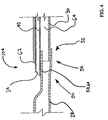
- Catheter 20 includes a hub 22 connected to the proximal end of an elongate shaft 24.
- Elongate shaft 24 includes a proximal shaft portion 26, a middle shaft portion 28, and a distal shaft portion 30.
- Proximal shaft portion 26, middle shaft portion 28, and distal shaft portion 30 each have a proximal end and a distal end. As shown in Figure 1, the distal end of proximal shaft portion 26 is fixed to the proximal end of middle shaft portion 28. Likewise, the distal end of middle shaft portion 28 is fixed to the proximal end of distal shaft portion at a transition region 32.
- catheter 20 may include more or less than three shaft portions without deviating from the scope of the present invention.
- catheter 20 includes a proximal guidewire port 34 disposed proximate transition region 32.
- catheter 20 also includes a distal guidewire port 36 disposed proximate the distal end of distal shaft portion 30.
- Elongate shaft 24 includes a plurality of walls 38 defining a guidewire lumen 40 which is in fluid communication with proximal guidewire port 34 and distal guidewire port 36.
- Elongate shaft 24 also includes a plurality of walls defining an inflation lumen 42.
- Inflation lumen 42 is in fluid communication with a balloon 44 and a port 46 of hub 22.
- a fluid source 48 (not shown) may be coupled to a port 46 of hub 22.
- Balloon 44 may be inflated by urging fluid from fluid source 48 into balloon 44 via inflation lumen 42.
- Catheter 20 of Figure 1 is a type of catheter which may be generally referred to as a balloon catheter. Those of skill in the art will appreciate that methods and devices in accordance with the present invention may be used to fabricate other types of catheter.
- Figure 2 is a cross-sectional view of transition region 32 of catheter 20. As shown in Figure 2, distal portion 50 of middle shaft portion 28 has been bonded to proximal portion 52 of distal shaft portion 30. Guidewire lumen 40 extends between proximal guidewire port 34 and distal guidewire port 36 (not shown). Inflation lumen 42 extends through transition region 32.
- Figures 3-7 may be utilized to describe one method which may be used to fabricate transition region 32 of catheter 20.
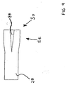
- Figure 3 is a plan view of distal portion 50 of middle shaft portion 28 prior to joining.
- middle shaft portion 28 has an enlarged portion 54 proximate its distal portion 50.
- enlarged portion 54 of middle shaft portion 28 facilitates the insertion of proximal portion 52 of distal shaft portion 30 into the lumen defined by distal portion 50 of middle shaft portion 28.
- middle shaft portion 28 does not include enlarged portion 54.
- proximal portion 52 of distal shaft portion 30 may be press fit into distal portion 50 of middle shaft portion 28.
- Middle shaft portion 28 also includes a plurality of slits 56 which define a tongue 58.
- middle shaft portion 28 may be comprised of many materials without deviating from the spirit and scope of the present invention.
- middle shaft portion 28 may include an inner tube comprised of PTFE.
- middle shaft portion 28 may include a support member.
- a support member is comprised of a plurality of fibers wound in a braided pattern around an inner tube.
- middle shaft portion 28 is comprised of polyether block amide (PEBA).
- PEBA polyether block amide
- Polyether block amide is commercially available from Atomchel Polymers of Birdsboro, Pennsylvania under the tradename PEBAX.
- Middle shaft portion 28 may be fabricated using an extrusion process.
- Middle shaft portion 28 may also be comprised of other materials without deviating from the scope or spirit of this invention. Examples of materials which may be suitable in some applications include: polyethylene (PE), polypropylene (PP), polyvinylchloride (PVC), polyurethane, and PTFE.
- PE polyethylene
- PP polypropylene
- PVC polyvinylchloride
- PTFE polyurethane
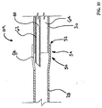
- Figure 4 is a cross sectional view of an assembly 104 including middle shaft portion 28.
- tongue 58 of middle shaft portion 28 has been positioned under an inner tubular member or inner 62. When tongue 58 is positioned in this way, it forms a shelf 60.
- the proximal end of distal shaft portion 30 has been inserted into enlarged portion 54 of middle shaft portion 28.
- An inner tubular member or inner 62 is disposed proximate shelf 60 formed by tongue 58.
- a portion of inner tubular member is disposed within a distal lumen 64 defined by distal shaft portion 30.
- inner 62 defines proximal guidewire port 34, guidewire lumen 40 and distal guidewire port 36 (not shown).
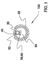
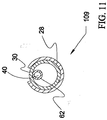
- Figure 5 is a transverse cross sectional view of assembly 104 of Figure 4.
- middle shaft portion 28 is shown disposed about distal shaft portion 30.
- Inner 62 is shown disposed within distal lumen 64 of distal shaft portion 30, proximate shelf 60 formed by tongue 50.
- Guide wire lumen 40 defined by inner 62 is also shown in Figure 5.
- Figure 6 is a cross sectional view of assembly 104 of Figure 4 and Figure 5 with a first mandrel 66 disposed within the lumens of middle shaft portion 28 and distal shaft portion 30.
- a second mandrel 68 is disposed within guidewire lumen 40 of inner 62.
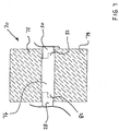
- Figure 7 is a cross sectional view of a compression fixture 70 including a first die 72 and a second die 74.
- a sleeve 76 is disposed about assembly 104 of Figure 6.
- Middle shaft portion 28 and distal shaft portion 30 are shown extending beyond the ends of sleeve 76.
- Sleeve 76 and assembly 104 are disposed between first die 72 and second die 74 of compression fixture 70.
- sleeve 76 includes a plurality of ears 82.
- sleeve 76 is comprised of PTFE heat shrink tubing.
- polyolefin heat shrink can be used. Suitable PTFE and polyolefin heat shrink tubing is commercially available from Zeus Industries of Orangeburg, South Carolina and Raychem Corporation of Menlo Park, California.
- sleeve 76 may be comprised of materials other than PTFE shrink tubing without deviating from the spirit and scope of the present invention.
- Sleeve 76 need not necessarily be comprised of shrink tubing and sleeve 76 need not be comprised of PTFE.
- Figure 8 is a plan view of a lens 78 capable of focusing a laser beam 80.
- laser beam 80 is illuminating a portion of assembly 104 and sleeve 76.
- a method of fabricating transition region 32 of catheter 20 may be described with reference to Figures 3 -7.
- a presently preferred method in accordance with the present invention begins with the step of forming enlarged portion 54 proximate the distal end of middle shaft portion 28. This may be accomplished using a heat forming process.
- a suitable heat forming process typically includes the steps of applying heat and forming the material. Forming the material may by accomplished by urging an appropriately shaped mandrel into the lumen of middle shaft portion 28.
- a number of methods may be used to apply heat to the material of middle shaft portion 28 including convection, conduction and radiation.
- An example of heating with radiant energy is directing infrared energy from an infrared heat source at the material. Infrared energy sources suitable for this process are commercially available from Research Incorporated of Minnetonka, Minnesota.
- An example of heating with convection is directing a flow of hot air from a hot air gun so that it impinges on the material. Hot air guns suitable for this application are commercially available from Leister Elektro-Geratebau of Lucerne, Switzerland.
- Enlarged portion 54 of middle shaft portion 28 may be allowed to cool.
- Slits 56 may be formed by cutting through the material of middle shaft portion with a cutting tool. Any suitable cutting tool may be used, including a knife or a diagonal cutter.
- slits 56 define a tongue 58.
- a process in accordance with the present embodiment includes the step of positioning tongue 58 at an obtuse angle relative to the longitudinal axis of middle shaft portion 28. In this manner, tongue 58 forms a shelf 60.
- An inner 62 may be positioned proximate shelf 60 as shown in Figure 4. A distal end of inner 62 is inserted into a lumen defined by distal shaft portion 30.
- Proximal portion 52 of distal shaft portion 30 is inserted into the lumen defined by distal portion 50 of middle shaft portion 28.
- a first mandrel 66 may be inserted into the lumen of middle shaft portion 28 and the lumen of distal shaft portion 30 as shown in Figure 6.
- a second mandrel 68 may be inserted into guidewire lumen 40 of inner 62.
- the assembly of Figure 6 may be inserted into a sleeve 76. Heat and pressure may be applied to transition region 32.
- the assembly is positioned between a first die and a second die of a compression fixture. The compression fixture may then be closed around the assembly.
- closing the first die and the second die upon the assembly substantially simultaneously provides for uniform heating of the assembly when the dies are heated.
- the first die and the second die each include a cavity.
- the cavity of the first die and the cavity of the second die are adapted to apply pressure to an outer surface of the assembly.
- compression fixture 70 may include a plurality of electric heaters. These electric heaters would be positioned in intimate contact with compression fixture 70 and would conduct heat to it. Compression fixture 70 would likewise conduct heat to transition region 32.
- Electric heaters suitable for heating compression fixture 70 are commercially available from Watlow Incorporated of St. Louis, Missouri. An example of heating with radiant energy is exposing the regions to be heated to radio frequency energy. An example of heating with convection is placing the compression fixture in a temperature chamber. Temperature chambers suitable for this process are commercially available from Thermotron Corporation of New Holland, Michigan. The assembly may be allowed to cool and the assembly may be removed form compression fixture 70.
- Assembly 104 may be placed in a rotating fixture. Assembly 104 may be rotated and illuminated with a laser beam. After exposure to laser energy, assembly 104 may be allowed to cool.
- the assembly may be submersed in a relatively cool fluid to speed cooling of the assembly.
- fluids which may be suitable for some applications include water and air. Relatively cool air may also be impinged onto the assembly.
- Cold air generators suitable for this purpose are commercially available from ITW Vortec of Cincinnati, Ohio and Exair Corporation of Cincinnati, Ohio.
- Sleeve 76 may be removed from catheter 20 by grasping ears 82 and applying the force required to tear sleeve 76.
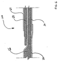
- FIG. 9 is a plan view of distal portion 50 of middle shaft portion 28 prior to joining with an additional method in accordance with the present invention.
- middle shaft portion 28 has an enlarged portion 54 proximate its distal portion 50.
- enlarged portion 54 of middle shaft portion 28 facilitates the insertion of proximal portion 52 of distal shaft portion 30 into the lumen defined by distal portion 50 of middle shaft portion 28.
- the walls of middle shaft portion 28 define a slot 84 disposed proximate the distal end of middle shaft portion 28.
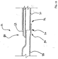
- Figure 10 is a cross sectional view of an assembly 109 including middle shaft portion 28.
- the proximal end of distal shaft portion 30 is disposed within the lumen defined by enlarged portion 54 of middle shaft portion 28.
- An inner tubular member or inner 62 is disposed within the lumens defined by middle shaft portion 28 and distal shaft portion 30, and proximate slot 84 of middle shaft portion 28.
- Figure 11 is a transverse cross sectional view of assembly 109 of Figure 10.
- middle shaft portion 28 is shown disposed about distal shaft portion 30.
- Inner 62 is shown disposed within the lumens defined by middle shaft portion 28 and distal shaft portion 30.
- a guide wire lumen 40 defined by inner 62 is also shown in Figure 11.
- a method in accordance with the present invention may be described with reference to Figures 8 and 9.
- the method typically begins with the steps of forming enlarged portion 54 proximate the distal end of middle shaft portion 28 and cutting slot 84 as shown in Figure 9.
- a process in accordance with the present invention also includes the step of inserting the distal end of inner 62 into distal lumen 64 defined by distal shaft portion 30.
- Proximal portion 52 of distal shaft portion 30 is inserted into the lumen defined by distal portion 50 of middle shaft portion 28 and inner 62 is arranged so that it extends through slot 84.
- a first mandrel 66 may be inserted into the lumen of middle shaft portion 28 and the lumen of distal shaft portion 30.
- a second mandrel 68 may be inserted into guidewire lumen 40 of inner 62.
- the assembly of Figure 10 may be inserted into a sleeve 76, and positioned in a compression fixture 70. Heat and pressure may the be applied to transition region 32.
- Assembly 109 is then removed from compression fixture 70 and transition region 32 is fused.
- the step of fusing transition region 32 may include the step of illuminating sleeve 76 and transition region 32 with laser light.
- transition region 32 is rotated while it is illuminated with laser light. After exposure to laser energy, assembly 109 may be allowed to cool.
- Sleeve 76 may be removed from catheter 20 by tearing or cutting.
- Figure 12 is a plan view of distal portion 50 of a middle shaft portion 28 in accordance with an additional embodiment in accordance with the present invention.
- Middle shaft portion 28 includes an enlarged portion 54 proximate its distal portion 50.
- a bevel 86 has been cut into distal portion 50 of middle shaft portion 28. Bevel 86 defines an opening 88.
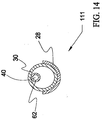
- Figure 13 is a cross sectional view of an assembly 111 including middle shaft portion 28 of Figure 12.
- proximal end 52 of distal shaft portion 30 is disposed proximate enlarged portion 54 of middle shaft portion 28.
- An inner tubular member or inner 62 is disposed within the lumens defined by middle shaft portion 28 and distal shaft portion 30. Inner 62 extends through opening 88 defined by bevel 86 of middle shaft portion 28. Methods in accordance with the present invention may be used to fuse assembly 111 of Figure 13 to form transition region 32 of catheter 20.
- Figure 14 is a transverse cross sectional view of assembly 111 of Figure 13.
- middle shaft portion 28 is shown disposed about distal shaft portion 30.
- Inner 62 is shown disposed within the lumens defined by middle shaft portion 28 and distal shaft portion 30.
- a guide wire lumen 40 defined by inner 62 is also shown in Figure 14.
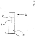
- FIG. 15 is a plan view of distal portion 50 of a middle shaft portion 28 in accordance with yet another embodiment in accordance with the present invention.
- Middle shaft portion 28 defines an aperture 90.
- a fold 92 is formed by the wall of middle shaft portion 28 proximate aperture 90.
- Figure 16 is a cross sectional view of an assembly 113 including middle shaft portion 28 of Figure 15.
- proximal end 52 of distal shaft portion 30 is disposed within the lumen defined by distal portion 50 of middle shaft portion 28.
- An inner tubular member or inner 62 is disposed within the lumens defined by middle shaft portion 28 and distal shaft portion 30. Inner 62 extends through aperture 90 and is disposed proximate fold 92. Methods in accordance with the present invention may be used to fuse assembly 113 of Figure 16 to form transition region 32 of catheter 20.
- Figure 17 is a transverse cross sectional view of assembly 113 of Figure 16.
- middle shaft portion 28 is shown disposed about distal shaft portion 30.
- Inner 62 is shown disposed within the lumens defined by middle shaft portion 28 and distal shaft portion 30.
- a guide wire lumen 40 defined by inner 62 is also shown in Figure 17.
- Figure 18 is a plan view of a compression fixture 170 including a first die 172 and a second die 174.
- First die 172 includes a cavity 182.
- second die 174 includes a cavity 184.
- Figure 19 is an additional plan view of compression fixture 170 of Figure 18.
Abstract
Description
- The present invention relates generally to catheters for performing medical procedures. More particularly, the present invention relates to methods of fabricating catheter shafts having one or more guidewire ports and two or more tubular members.
- Intravascular catheters are currently utilized in a wide variety of minimally-invasive medical procedures. Generally, an intravascular catheter enables a physician to remotely perform a medical procedure by inserting the catheter into the vascular system of the patient at a location that is easily accessible and thereafter navigating the catheter to the desired target site. By this method, virtually any target site in the patient's vascular system may be remotely accessed, including the coronary, cerebral, and peripheral vasculature.
- Typically, the catheter enters the patient's vasculature at a convenient location such as a blood vessel in the neck or near the groin. Once the distal portion of the catheter has entered the patient's vascular system the physician may urge the distal tip forward by applying longitudinal forces to the proximal portion of the catheter. For the catheter to effectively communicate these longitudinal forces it is desirable that the catheter have a high level of pushability and kink resistance.
- Frequently the path taken by a catheter through the vascular system is tortuous, requiring the catheter to change direction frequently. In some cases, it may even be necessary for the catheter to double back on itself. In order for the catheter to conform to a patient's tortuous vascular system, it is desirable that intravascular catheters be very flexible, particularly in the distal portion.
- While advancing the catheter through the tortuous path of the patients vasculature, physicians often apply torsional forces to the proximal portion of the catheter to aid in steering the catheter. To facilitate the steering process, the distal portion of the catheter may include a plurality of bends or curves. Torsional forces applied on the proximal end must translate to the distal end to aid in steering. It is therefore desirable that an intravascular catheter have a relatively high level of torquability to facilitate steering.
- After the intravascular catheter has been navigated through the patient's vascular system so that its distal end is adjacent the target site, the catheter may be used for various diagnostic and/or therapeutic purposes. One example of a diagnostic use for an intravascular catheter is the delivery of radiopaque contrast solution to enhance fluoroscopic visualization. In this application, the intravascular catheter provides a fluid path leading from a location outside the body to a desired location inside the body of a patient. In order to maintain a fluid path, it is desirable that the intravascular catheter be sufficiently resistant to kinking. In addition, because such fluids are delivered under pressure, it is desirable that the intravascular catheter be sufficiently resistant to bursting or leaking.
- Examples of therapeutic purposes for intravascular catheters include percutaneous transluminal angioplasty (PTA) and percutaneous transluminal coronary angioplasty (PTCA). These angioplasty techniques typically involve the use of a guide catheter and a balloon catheter. During these procedures, the distal end of the guide catheter is typically inserted into the femoral artery located near the groin of the patient. The guide catheter is urged through the vasculature of the patient until its distal end is proximate the restriction. In many cases, the distal end of the guide catheter is positioned in the ostium of the coronary artery. The balloon catheter may then be fed through a lumen in the guide catheter such that the balloon is positioned proximate a restriction in a diseased vessel. The balloon is then inflated and the restriction in the vessel is opened. In this application, it is desirable that the guide catheter provide a low friction path for the balloon catheter. The balloon is inflated by urging a liquid though the elongate shaft of the balloon catheter and into the balloon. In this application, the balloon catheter must provide an unobstructed path for the inflation fluid. It is also desirable that the catheter be substantially free of leaks.
- As described at length above, it is desirable to combine a number of performance features in an intravascular catheter. It is desirable that the catheter have a relatively high level of pushability and torqueability. It is also desirable that a catheter be relatively flexible, particularly near it's distal end. The need for this combination of performance features is often addressed by building a catheter which has two or more discrete tubular members having different performance characteristics. For example, a relatively flexible distal section may be spliced to a relatively rigid proximal section. When a catheter is formed from two or more discrete tubular members, it is necessary to form a bond between the distal end of one tubular member and the proximal end of another tubular member.
- Intravascular catheters are often used in conjunction with a guidewire. When this is the case, the guidewire may be advanced through the patient's vasculature until its distal tip has reached a desired target location. Once the distal portion of the guidewire has reached the desired location, a catheter may be threaded onto the guidewire and urged distally until the distal end of the catheter is proximate the target location.
- Intravascular catheters adapted for use with guidewire typically fall into one of two categories: 1) single operator exchange (SOE); or 2) over-the-wire types. An over-the-wire type of catheter includes a guidewire lumen extending from the distal tip of the catheter to the proximal end of the catheter. Whereas, a single operator exchange catheter typically includes a relatively short guidewire lumen proximate the distal end of the catheter.
- Single operator exchange catheters were developed in response to difficulties encountered when exchanging over-the-wire catheters. During a medical procedure utilizing intravascular catheters it is sometimes necessary to withdraw one catheter and replace it with a second catheter. Generally the catheter is withdrawn from the patient over the guidewire leaving the guidewire in place with the distal tip of the guidewire proximate the target location of the patient's anatomy.
- In order to withdraw the catheter while leaving the guidewire in the desired location, a portion of the guidewire is typically grasped by the physician in order to hold the guidewire in place. During this procedure, a portion of the guidewire must be exposed at all times so that it is available for the physician to grasp. In the case of over-the-wire catheter, this requires that the length of guidewire extending beyond the patient's body be longer than the catheter. In some cases, length may be added to the guidewire using a guidewire extension. The long exchange wire or guidewire extension extending beyond the patient's body must be managed during the catheter exchange procedure. In particular, contamination must be avoided by making sure that the guidewire is not dropped from the sterile field. This procedure is awkward and typically requires two persons.
- An SOE catheter, on the other hand, has a relatively short guidewire lumen. The length of guidewire extending from the patient need only be slightly longer than the guidewire lumen of the catheter. The physician may anchor or hold the guidewire as the catheter is removed from the body with the exchange occurring over the shorter guidewire lumen. The guidewire lumen of an SOE catheter typically includes a distal guidewire port disposed at the distal tip of the catheter and a proximal guidewire port disposed proximally of the distal end of the catheter. It is desirable to fabricate SOE catheters including a proximal guidewire port while maintaining the other desirable performance features described previously.
- US-A-5,702,437 relates to an over-the-wire balloon dilatation catheter having a stainless steel hypo tube catheter shaft, an intermediate sleeve section bonded to the shaft and a distal balloon section connected to the sleeve section. The sleeve section is formed from relatively flexible polymer materials and includes an inner core tube which defines a guide wire lumen extending only through a distal portion of the catheter to facilitate fast balloon catheter exchanges. A distal end of the hypo tube shaft is crimped laterally and the core tube is nested and bonded within the crimp to provide a proximal outlet for the guide wire lumen. The hypo tube shaft provides an inflation lumen for the balloon, with the inflation lumen being continued as an annular inflation lumen through the sleeve section where an outer sleeve is bonded about the core tube and extends from the distal end of the hypo tube shaft to the balloon section. A kink-resistant coil structure extends distally from the distal end of the hypo tube shaft to provide a gradual change in stiffness along the length of the catheter from the relatively stiff hypo tube shaft to the relatively flexible distal portion of the catheter.
- In an alternative configuration instead of providing a crimp structure in the distal end of the hypotube shaft, an aperture is provided adjacent to and proximal of the distal end of the hypotube shaft. The aperture is aligned and sealably coupled to the inner core tube to define the guidewire lumen proximal outlet.
- The present invention relates generally to catheters for performing medical procedures. More particularly, the present invention relates to methods of fabricating catheters having one or more guidewire ports and two or more tubular members.
- A catheter assembly in accordance with the methods of the present invention includes an elongate shaft having a proximal shaft portion, a middle shaft portion, and a distal shaft portion. Proximal shaft portion, middle shaft portion, and distal shaft portion each have a proximal end and a distal end. The distal end of the proximal shaft portion is fixed to the proximal end of the middle shaft portion. Likewise, the distal end of middle shaft portion is fixed to the proximal end of distal shaft portion at a transition region.
- In a presently preferred embodiment the catheter includes a proximal guidewire port disposed proximate the transition region. The catheter further includes a distal guidewire port disposed proximate the distal end of the distal shaft portion. The elongate shaft of the catheter includes a plurality of walls defining a guidewire lumen which is in fluid communication with the proximal guidewire port and the distal guidewire port.
- The elongate shaft also includes a plurality of walls defining an inflation lumen. The inflation lumen is in fluid communication with a balloon disposed proximate the distal end of the elongate shaft of the catheter. The inflation lumen is also in fluid communication with a port of a hub assembly disposed at the proximal end of the elongate shaft of the catheter. A fluid source may be coupled to the port of the hub assembly. The balloon may be inflated by urging fluid from the fluid source into the balloon via the inflation lumen.
- The inflation lumen and the guidewire lumen both pass through the transition region of the catheter. In a presently preferred, embodiment, the distal end of middle shaft portion is fixed to the proximal end of distal shaft portion proximate the transition region of the catheter. Methods of fabricating a catheter having such a transition region are disclosed.
-
- Figure 1 is a plan view of an exemplary embodiment of a catheter in accordance with the methods of the present invention;
- Figure 2 is a cross-sectional view of the
transition region 32 of an exemplary embodiment of a catheter in accordance with the methods of the present invention; - Figure 3 is a plan view of the distal portion of an generally tubular member in accordance with an exemplary embodiment of the present invention;
- Figure 4 is a cross sectional view of an assembly in accordance with the methods of the present invention, the assembly includes two shaft portions, and an inner
- Figure 5 is a transverse cross sectional view of the assembly of Figure
- Figure 6 is a cross sectional view of the assembly of Figure 4 with a first mandrel disposed within the lumens of the middle shaft portion and the distal shaft portion and a second mandrel disposed within the guidewire lumen of the inner tubular member;
- Figure 7 is a cross sectional view of a compression fixture including a first die and a second die,
- Figure 8 is a plan view illustrating a method which may be used to fuse the transition portion of a catheter;
- Figure 9 is a plan view of the distal portion of an generally tubular member in accordance with an exemplary embodiment of the present invention;
- Figure 10 is a cross sectional view of an assembly in accordance with the methods of the present invention, the assembly includes two shaft portions, and an inner tubular member;
- Figure 11 is a transverse cross sectional view of the assembly of figure 10;
- Figure 12 is a plan view of the distal portion of an generally tubular member in accordance with an exemplary embodiment of the present invention;
- Figure 13 is a cross sectional view of an assembly in accordance with the methods of the present invention, the assembly includes two shaft portions, and an inner tubular member;
- Figure 14 is a transverse cross sectional view of the assembly of figure 13;
- Figure 15 is a plan view of the distal portion of an generally tubular member in accordance with an exemplary embodiment of the present invention;
- Figure 16 is a cross sectional view of an assembly in accordance with the method of the present invention, the assembly includes two shaft portions, and an inner tubular member;
- Figure 17 is a transverse cross sectional view of the assembly of figure 16;
- Figure 18 is a plan view of a compression fixture including a first die having a cavity, and a second die having a cavity; and
- Figure 19 is a plan view of the compression fixture of Figure 18.
- The following detailed description should be read with reference to the drawings, in which like elements in different drawings are numbered identically. The drawings which are not necessarily to scale, depict selected embodiments and are not intended to limit the scope of the invention as recited in the claims. Examples of constructions, materials, dimensions, and manufacturing processes are provided for various elements. Those skilled in the art will recognize that many of the examples provided have suitable alternatives which may be utilized. The subject-matter of the invention is defined by the features of the claims.
- Refer now to Figure 1, which illustrates a plan view of a
catheter 20 in accordance with an exemplary embodiment of the methods of the present invention.Catheter 20 includes ahub 22 connected to the proximal end of anelongate shaft 24. -
Elongate shaft 24 includes aproximal shaft portion 26, amiddle shaft portion 28, and adistal shaft portion 30.Proximal shaft portion 26,middle shaft portion 28, anddistal shaft portion 30 each have a proximal end and a distal end. As shown in Figure 1, the distal end ofproximal shaft portion 26 is fixed to the proximal end ofmiddle shaft portion 28. Likewise, the distal end ofmiddle shaft portion 28 is fixed to the proximal end of distal shaft portion at atransition region 32. Those of skill in the art will appreciate thatcatheter 20 may include more or less than three shaft portions without deviating from the scope of the present invention. - In the embodiment of Figure 1,
catheter 20 includes aproximal guidewire port 34 disposedproximate transition region 32.Catheter 20 also includes a distal guidewire port 36 disposed proximate the distal end ofdistal shaft portion 30.Elongate shaft 24 includes a plurality of walls 38 defining aguidewire lumen 40 which is in fluid communication withproximal guidewire port 34 and distal guidewire port 36. -
Elongate shaft 24 also includes a plurality of walls defining aninflation lumen 42.Inflation lumen 42 is in fluid communication with aballoon 44 and aport 46 ofhub 22. A fluid source 48 (not shown) may be coupled to aport 46 ofhub 22.Balloon 44 may be inflated by urging fluid from fluid source 48 intoballoon 44 viainflation lumen 42.Catheter 20 of Figure 1 is a type of catheter which may be generally referred to as a balloon catheter. Those of skill in the art will appreciate that methods and devices in accordance with the present invention may be used to fabricate other types of catheter. - Figure 2 is a cross-sectional view of
transition region 32 ofcatheter 20. As shown in Figure 2,distal portion 50 ofmiddle shaft portion 28 has been bonded toproximal portion 52 ofdistal shaft portion 30.Guidewire lumen 40 extends between proximalguidewire port 34 and distal guidewire port 36 (not shown).Inflation lumen 42 extends throughtransition region 32. - Figures 3-7 may be utilized to describe one method which may be used to fabricate
transition region 32 ofcatheter 20. Figure 3 is a plan view ofdistal portion 50 ofmiddle shaft portion 28 prior to joining. In Figure 3,middle shaft portion 28 has anenlarged portion 54 proximate itsdistal portion 50. In a presently preferred embodiment of the present invention,enlarged portion 54 ofmiddle shaft portion 28 facilitates the insertion ofproximal portion 52 ofdistal shaft portion 30 into the lumen defined bydistal portion 50 ofmiddle shaft portion 28. Alternate embodiments of the present invention have been envisioned in whichmiddle shaft portion 28 does not includeenlarged portion 54. In these envisioned embodiments,proximal portion 52 ofdistal shaft portion 30 may be press fit intodistal portion 50 ofmiddle shaft portion 28.Middle shaft portion 28 also includes a plurality ofslits 56 which define atongue 58. - Those of skill in the art will appreciate that
middle shaft portion 28 may be comprised of many materials without deviating from the spirit and scope of the present invention. For example,middle shaft portion 28 may include an inner tube comprised of PTFE. By way of a second example,middle shaft portion 28 may include a support member. In a preferred embodiment, a support member is comprised of a plurality of fibers wound in a braided pattern around an inner tube. In a preferred embodiment,middle shaft portion 28 is comprised of polyether block amide (PEBA). Polyether block amide is commercially available from Atomchel Polymers of Birdsboro, Pennsylvania under the tradename PEBAX.Middle shaft portion 28 may be fabricated using an extrusion process. In this process, molten PEBA is extruded onto the combined layers of the inner tube and the support member. When this process is used, the PEBA material fills any interstitial spaces in the support member. It is to be understood that other manufacturing processes can be used without deviating from the spirit and scope of the present invention.Middle shaft portion 28 may also be comprised of other materials without deviating from the scope or spirit of this invention. Examples of materials which may be suitable in some applications include: polyethylene (PE), polypropylene (PP), polyvinylchloride (PVC), polyurethane, and PTFE. - Figure 4 is a cross sectional view of an
assembly 104 includingmiddle shaft portion 28. In Figure 4,tongue 58 ofmiddle shaft portion 28 has been positioned under an inner tubular member or inner 62. Whentongue 58 is positioned in this way, it forms a shelf 60. The proximal end ofdistal shaft portion 30 has been inserted intoenlarged portion 54 ofmiddle shaft portion 28. An inner tubular member or inner 62 is disposed proximate shelf 60 formed bytongue 58. As show in Figure 4, a portion of inner tubular member is disposed within adistal lumen 64 defined bydistal shaft portion 30. In a presently preferred embodiment, inner 62 definesproximal guidewire port 34,guidewire lumen 40 and distal guidewire port 36 (not shown). - Figure 5 is a transverse cross sectional view of
assembly 104 of Figure 4. In Figure 5,middle shaft portion 28 is shown disposed aboutdistal shaft portion 30.Inner 62 is shown disposed withindistal lumen 64 ofdistal shaft portion 30, proximate shelf 60 formed bytongue 50.Guide wire lumen 40 defined by inner 62 is also shown in Figure 5. - Figure 6 is a cross sectional view of
assembly 104 of Figure 4 and Figure 5 with afirst mandrel 66 disposed within the lumens ofmiddle shaft portion 28 anddistal shaft portion 30. In Figure 6 asecond mandrel 68 is disposed withinguidewire lumen 40 of inner 62. - Figure 7 is a cross sectional view of a
compression fixture 70 including afirst die 72 and asecond die 74. Asleeve 76 is disposed aboutassembly 104 of Figure 6.Middle shaft portion 28 anddistal shaft portion 30 are shown extending beyond the ends ofsleeve 76.Sleeve 76 andassembly 104 are disposed betweenfirst die 72 and second die 74 ofcompression fixture 70. - In the embodiment of Figure 7,
sleeve 76 includes a plurality ofears 82. In a preferred embodiment,sleeve 76 is comprised of PTFE heat shrink tubing. In another embodiment, polyolefin heat shrink can be used. Suitable PTFE and polyolefin heat shrink tubing is commercially available from Zeus Industries of Orangeburg, South Carolina and Raychem Corporation of Menlo Park, California. Those of skill in the art will appreciate thatsleeve 76 may be comprised of materials other than PTFE shrink tubing without deviating from the spirit and scope of the present invention.Sleeve 76 need not necessarily be comprised of shrink tubing andsleeve 76 need not be comprised of PTFE. - Figure 8 is a plan view of a
lens 78 capable of focusing alaser beam 80. In Figure 8,laser beam 80 is illuminating a portion ofassembly 104 andsleeve 76. A method of fabricatingtransition region 32 ofcatheter 20 may be described with reference to Figures 3 -7. - A presently preferred method in accordance with the present invention begins with the step of forming
enlarged portion 54 proximate the distal end ofmiddle shaft portion 28. This may be accomplished using a heat forming process. A suitable heat forming process typically includes the steps of applying heat and forming the material. Forming the material may by accomplished by urging an appropriately shaped mandrel into the lumen ofmiddle shaft portion 28. - A number of methods may be used to apply heat to the material of
middle shaft portion 28 including convection, conduction and radiation. An example of heating with radiant energy is directing infrared energy from an infrared heat source at the material. Infrared energy sources suitable for this process are commercially available from Research Incorporated of Minnetonka, Minnesota. An example of heating with convection is directing a flow of hot air from a hot air gun so that it impinges on the material. Hot air guns suitable for this application are commercially available from Leister Elektro-Geratebau of Lucerne, Switzerland. -
Enlarged portion 54 ofmiddle shaft portion 28 may be allowed to cool.Slits 56 may be formed by cutting through the material of middle shaft portion with a cutting tool. Any suitable cutting tool may be used, including a knife or a diagonal cutter. As shown in Figure 3, slits 56 define atongue 58. As shown if Figure 4, a process in accordance with the present embodiment includes the step of positioningtongue 58 at an obtuse angle relative to the longitudinal axis ofmiddle shaft portion 28. In this manner,tongue 58 forms a shelf 60. An inner 62 may be positioned proximate shelf 60 as shown in Figure 4. A distal end of inner 62 is inserted into a lumen defined bydistal shaft portion 30.Proximal portion 52 ofdistal shaft portion 30 is inserted into the lumen defined bydistal portion 50 ofmiddle shaft portion 28. - A
first mandrel 66 may be inserted into the lumen ofmiddle shaft portion 28 and the lumen ofdistal shaft portion 30 as shown in Figure 6. Also as shown in Figure 6, asecond mandrel 68 may be inserted intoguidewire lumen 40 of inner 62. The assembly of Figure 6 may be inserted into asleeve 76. Heat and pressure may be applied to transitionregion 32. In a presently preferred method, the assembly is positioned between a first die and a second die of a compression fixture. The compression fixture may then be closed around the assembly. In this presently preferred method, closing the first die and the second die upon the assembly substantially simultaneously provides for uniform heating of the assembly when the dies are heated. In a presently preferred embodiment, the first die and the second die each include a cavity. Also, in a presently preferred embodiment, the cavity of the first die and the cavity of the second die are adapted to apply pressure to an outer surface of the assembly. - A number of methods may be used to
heat transition region 32 including convection, conduction and radiation. For example,compression fixture 70 may include a plurality of electric heaters. These electric heaters would be positioned in intimate contact withcompression fixture 70 and would conduct heat to it.Compression fixture 70 would likewise conduct heat to transitionregion 32. Electric heaters suitable forheating compression fixture 70 are commercially available from Watlow Incorporated of St. Louis, Missouri. An example of heating with radiant energy is exposing the regions to be heated to radio frequency energy. An example of heating with convection is placing the compression fixture in a temperature chamber. Temperature chambers suitable for this process are commercially available from Thermotron Corporation of New Holland, Michigan. The assembly may be allowed to cool and the assembly may be removedform compression fixture 70. -
Assembly 104 may be placed in a rotating fixture.Assembly 104 may be rotated and illuminated with a laser beam. After exposure to laser energy,assembly 104 may be allowed to cool. - The assembly may be submersed in a relatively cool fluid to speed cooling of the assembly. Examples of fluids which may be suitable for some applications include water and air. Relatively cool air may also be impinged onto the assembly. Cold air generators suitable for this purpose are commercially available from ITW Vortec of Cincinnati, Ohio and Exair Corporation of Cincinnati, Ohio.
Sleeve 76 may be removed fromcatheter 20 by graspingears 82 and applying the force required to tearsleeve 76. - It should be understood that steps may be omitted from this process without deviating from the scope of the invention as recited in the claims. Other methods have been envisioned. Additional exemplary embodiments of the present invention are illustrated in the Figures which follow.
- Figure 9 is a plan view of
distal portion 50 ofmiddle shaft portion 28 prior to joining with an additional method in accordance with the present invention. In Figure 9,middle shaft portion 28 has anenlarged portion 54 proximate itsdistal portion 50. In a presently preferred embodiment of the present invention,enlarged portion 54 ofmiddle shaft portion 28 facilitates the insertion ofproximal portion 52 ofdistal shaft portion 30 into the lumen defined bydistal portion 50 ofmiddle shaft portion 28. The walls ofmiddle shaft portion 28 define aslot 84 disposed proximate the distal end ofmiddle shaft portion 28. - Figure 10 is a cross sectional view of an
assembly 109 includingmiddle shaft portion 28. In Figure 10, the proximal end ofdistal shaft portion 30 is disposed within the lumen defined byenlarged portion 54 ofmiddle shaft portion 28. An inner tubular member or inner 62 is disposed within the lumens defined bymiddle shaft portion 28 anddistal shaft portion 30, andproximate slot 84 ofmiddle shaft portion 28. - Figure 11 is a transverse cross sectional view of
assembly 109 of Figure 10. In Figure 11,middle shaft portion 28 is shown disposed aboutdistal shaft portion 30.Inner 62 is shown disposed within the lumens defined bymiddle shaft portion 28 anddistal shaft portion 30. Aguide wire lumen 40 defined by inner 62 is also shown in Figure 11. - A method in accordance with the present invention may be described with reference to Figures 8 and 9. The method typically begins with the steps of forming
enlarged portion 54 proximate the distal end ofmiddle shaft portion 28 and cuttingslot 84 as shown in Figure 9. - As shown if Figure 10, a process in accordance with the present invention also includes the step of inserting the distal end of inner 62 into
distal lumen 64 defined bydistal shaft portion 30.Proximal portion 52 ofdistal shaft portion 30 is inserted into the lumen defined bydistal portion 50 ofmiddle shaft portion 28 and inner 62 is arranged so that it extends throughslot 84. - A
first mandrel 66 may be inserted into the lumen ofmiddle shaft portion 28 and the lumen ofdistal shaft portion 30. Asecond mandrel 68 may be inserted intoguidewire lumen 40 of inner 62. The assembly of Figure 10 may be inserted into asleeve 76, and positioned in acompression fixture 70. Heat and pressure may the be applied to transitionregion 32. -
Assembly 109 is then removed fromcompression fixture 70 andtransition region 32 is fused. The step of fusingtransition region 32 may include the step of illuminatingsleeve 76 andtransition region 32 with laser light. In a presently preferred method in accordance with the present invention,transition region 32 is rotated while it is illuminated with laser light. After exposure to laser energy,assembly 109 may be allowed to cool.Sleeve 76 may be removed fromcatheter 20 by tearing or cutting. - Figure 12 is a plan view of
distal portion 50 of amiddle shaft portion 28 in accordance with an additional embodiment in accordance with the present invention.Middle shaft portion 28 includes anenlarged portion 54 proximate itsdistal portion 50. Abevel 86 has been cut intodistal portion 50 ofmiddle shaft portion 28.Bevel 86 defines anopening 88. - Figure 13 is a cross sectional view of an
assembly 111 includingmiddle shaft portion 28 of Figure 12. In the embodiment of Figure 13,proximal end 52 ofdistal shaft portion 30 is disposed proximateenlarged portion 54 ofmiddle shaft portion 28. An inner tubular member or inner 62 is disposed within the lumens defined bymiddle shaft portion 28 anddistal shaft portion 30.Inner 62 extends through opening 88 defined bybevel 86 ofmiddle shaft portion 28. Methods in accordance with the present invention may be used to fuseassembly 111 of Figure 13 to formtransition region 32 ofcatheter 20. - Figure 14 is a transverse cross sectional view of
assembly 111 of Figure 13. In Figure 14,middle shaft portion 28 is shown disposed aboutdistal shaft portion 30.Inner 62 is shown disposed within the lumens defined bymiddle shaft portion 28 anddistal shaft portion 30. Aguide wire lumen 40 defined by inner 62 is also shown in Figure 14. - Figure 15 is a plan view of
distal portion 50 of amiddle shaft portion 28 in accordance with yet another embodiment in accordance with the present invention.Middle shaft portion 28 defines anaperture 90. Afold 92 is formed by the wall ofmiddle shaft portion 28proximate aperture 90. - Figure 16 is a cross sectional view of an
assembly 113 includingmiddle shaft portion 28 of Figure 15. In the embodiment of Figure 16,proximal end 52 ofdistal shaft portion 30 is disposed within the lumen defined bydistal portion 50 ofmiddle shaft portion 28. An inner tubular member or inner 62 is disposed within the lumens defined bymiddle shaft portion 28 anddistal shaft portion 30.Inner 62 extends throughaperture 90 and is disposedproximate fold 92. Methods in accordance with the present invention may be used to fuseassembly 113 of Figure 16 to formtransition region 32 ofcatheter 20. - Figure 17 is a transverse cross sectional view of
assembly 113 of Figure 16. In Figure 17,middle shaft portion 28 is shown disposed aboutdistal shaft portion 30.Inner 62 is shown disposed within the lumens defined bymiddle shaft portion 28 anddistal shaft portion 30. Aguide wire lumen 40 defined by inner 62 is also shown in Figure 17. - Figure 18 is a plan view of a
compression fixture 170 including afirst die 172 and asecond die 174. First die 172 includes acavity 182. Likewise,second die 174 includes acavity 184. Figure 19 is an additional plan view ofcompression fixture 170 of Figure 18. - Having thus described the preferred embodiments of the present invention, those of skill in the art will readily appreciate thar yet other embodiments may be made and used within the scope of the claims hereto attached.
- Numerous advantages of the invention covered by this do cument have been set forth in the foregoing description. It will be understood, however, that this disclosure is, in many respects, only illustrative. Changes may be made in details, particularly in matters of shape, size, and arrangement of parts without exceeding the scope of the invention as defined in the claims.
Claims (28)
- A method of forming a catheter shaft (24) having a guidewire port, the method comprising the steps of:providing a first shaft portion (28) having a bonding portion disposed at a bonding end thereof, an ancillary end, and a lumen extending therethrough;providing a second shaft portion (30) having a bonding portion disposed at a bonding end thereof, an ancillary end, and a lumen extending therethrough;providing an inner member (62) having a proximal end, a distal end, and a lumen (40) extending therebetween;slitting a wall of the first shaft portion (28) to create an opening defined by the wall of the first shaft portion;inserting the proximal end of the inner member (62) through the opening defined by the wall of the first shaft portion (28);inserting the distal end of the inner member (62) into the lumen of the second shaft portion;inserting the bonding end of the second shaft portion (30) into a lumen defined by the bonding portion of the first shaft portion (28) such that the bonding portion of the first shaft portion overlays the bonding portion of the second shaft portion; andbonding the bonding portion of the first shaft portion (28) to the bonding portion of the second shaft portion (30).
- The method of claim 1, further including the step of applying heat and pressure to an outer surface of the bonding area of the first shaft portion (28).
- The method of claim 1, further including the step of positioning a generally tubular sleeve (76) so that it overlays the bonding area of the first shaft portion (28).
- The method of claim 1, further including the steps of positioning a generally tubular sleeve (76) so that it overlays the bonding area of the first shaft portion (28), and applying heat and pressure to an outer surface of the sleeve (76).
- The method of claim 1, further including the step of deforming the bonding end of the first shaft portion (28) to form a flare.
- The method of claim 1, wherein the first shaft portion (28) includes a support member comprising a plurality of filaments.
- The method of claim 1, wherein the step of bonding the bonding portion of the first shaft portion (28) to the bonding portion of the second shaft portion (30) includes the step of exposing the bonding portion of the first shaft portion (28) and the bonding portion of the second shaft portion (30) to electromagnetic waves.
- The method of claim 1, wherein the step of bonding the bonding portion of the first shaft portion (28) to the bonding portion of the second shaft portion (30) includes the step of exposing the bonding portion of the first shaft portion (28) and the bonding portion of the second shaft portion (30) to a hot fluid.
- The method of claim 1, wherein the step of bonding the bonding portion of the first shaft portion (28) to the bonding portion of the second shaft portion (30) includes the step of heating the bonding portion of the first shaft portion (28) and the bonding portion of the second shaft portion.
- The method of claim 1, wherein the step of bonding the bonding portion of the first shaft portion (28) to the bonding portion of the second shaft portion (30) includes the step of heating the bonding portion of the first shaft portion (28) and the bonding portion of the second shaft portion (30) with a laser beam.
- The method of claim 1, wherein the step of bonding the bonding portion of the first shaft portion (28) to the bonding portion of the second shaft portion (30) includes the steps of rotating the first shaft portion (28) and the second shaft portion (30) and directing a laser beam toward the bonding portion of the first shaft portion (28) and the bonding portion of the second shaft portion (30).
- The method of claim 1, wherein the step of bonding the bonding portion of the first shaft portion (28) to the bonding portion of the second shaft portion (30) includes the step of exposing the bonding portion of the first shaft portion (28) and the bonding portion of the second shaft portion (30) to hot air.
- The method of claim 1, wherein the first shaft portion (28) comprising a support member encased in a substrate material, the support member having a plurality of filaments and wherein the bonding step includes the step of heating the bonding portion of the first shaft portion (28) and the bonding portion of the second shaft portion (30) to form a bond therebetween, the method further comprising the steps of:inserting a first mandrel (66) into the lumen of the first shaft portion (28);inserting a second mandrel (68) into the lumen of the inner member (62); andapplying pressure to an outer surface of the bonding portion of the first shaft portion (28).
- The method of claim 13, further including the step of positioning a generally tubular sleeve (76) so that it overlays the bonding area of the first shaft portion (28).
- The method of claim 13, further including the step of deforming the bonding end of the first shaft portion (28) to form a flare.
- The method of claim 13, wherein the second shaft portion (30) includes a support member comprising a plurality of filaments.
- The method of claim 13, wherein the step of heating the bonding portion of the first shaft portion (28) and the bonding portion of the second shaft portion (30) includes the step of exposing the bonding portion of the first shaft portion (28) and the bonding portion of the second shaft portion (30) to electromagnetic waves.
- The method of claim 13, wherein the step of heating the bonding portion of the first shaft portion (28) and the bonding portion of the second shaft portion (30) includes the step of exposing the bonding portion of the first shaft portion (28) and the bonding portion of the second shaft portion (30) to a hot fluid.
- The method of claim 13, wherein the step of heating the bonding portion of the first shaft portion (28) and the bonding portion of the second shaft portion (30) includes the step of directing a laser beam toward the bonding portion of the first shaft portion (28) and the bonding portion of the second shaft portion (30).
- The method of claim 13, wherein the step of heating the bonding portion of the first shaft portion (28) and the bonding portion of the second shaft portion (30) includes the steps of rotating the first shaft portion (28) and the second shaft portion (30) and directing a laser beam toward the bonding portion of the first shaft portion (28) and the bonding portion of the second shaft portion (30).
- The method of claim 13, wherein the step of bonding the bonding portion of the first shaft portion (28) to the bonding portion of the second shaft portion (30) includes the step of exposing the bonding portion of the first shaft portion (28) and the bonding portion of the second shaft portion (30) to hot air.
- The method of claim 1, wherein the bonding step includes the step of heating the bonding portion of the first shaft portion (28) and the bonding portion of the second shaft portion (30) to form a bond therebetween, the method further comprising the steps of:deforming the bonding end of the first shaft portion (28) to form a flare;inserting a first mandrel (66) into the lumen of the first shaft portion (28);urging the first mandrel (66) further so that a portion thereof is disposed within the lumen of the second shaft portion (30);inserting a second mandrel (68) into the lumen of the inner member (62);positioning a generally tubular sleeve (76) so that it overlays the bonding portion of the first shaft portion (28),applying pressure to an outer surface of the sleeve (76); andremoving the pressure applied to the outer surface of the sleeve (76).
- The method of claim 22, wherein the first shaft portion (28) includes a support member comprising a plurality of filaments.
- The method of claim 22, wherein the step of heating the bonding portion of the first shaft portion (28) and the bonding portion of the second shaft portion (30) includes the step of exposing the bonding portion of the first shaft portion (28) and the bonding portion of the second shaft portion (30) to electromagnetic waves.
- The method of claim 22, wherein the step of heating the bonding portion of the first shaft portion (28) and the bonding portion of the second shaft portion (30) includes the step of exposing the bonding portion of the first shaft portion (28) and the bonding portion of the second shaft portion (30) to a hot fluid.
- The method of claim 22, wherein the step of heating the bonding portion of the first shaft portion (28) and the bonding portion of the second shaft portion (30) includes the step of directing a laser beam toward the bonding portion of the first shaft portion (28) and the bonding portion of the second shaft portion (30).
- The method of claim 22, wherein the step of heating the bonding portion of the first shaft portion (28) and the bonding portion of the second shaft portion (30) includes the steps of rotating the first shaft portion (28) and the second shaft portion (30) and directing a laser beam toward the bonding portion of the first shaft portion (28) and the bonding portion of the second shaft portion (30).
- The method of claim 22, wherein the step of bonding the bonding portion of the first shaft portion (28) to the bonding portion of the second shaft portion (30) includes the step of exposing the bonding portion of the first shaft portion (28) and the bonding portion of the second shaft portion (30) to hot air.
Applications Claiming Priority (3)
| Application Number | Priority Date | Filing Date | Title |
|---|---|---|---|
| US09/591,753 US6409863B1 (en) | 2000-06-12 | 2000-06-12 | Methods of fabricating a catheter shaft having one or more guidewire ports |
| US591753 | 2000-06-12 | ||
| PCT/US2001/015722 WO2001095973A2 (en) | 2000-06-12 | 2001-05-15 | Methods of fabricating a catheter shaft having one or more guidewire ports |
Publications (2)
| Publication Number | Publication Date |
|---|---|
| EP1294430A2 EP1294430A2 (en) | 2003-03-26 |
| EP1294430B1 true EP1294430B1 (en) | 2006-01-25 |
Family
ID=24367783
Family Applications (1)
| Application Number | Title | Priority Date | Filing Date |
|---|---|---|---|
| EP01935549A Expired - Lifetime EP1294430B1 (en) | 2000-06-12 | 2001-05-15 | Methods of fabricating a catheter shaft having one or more guidewire ports |
Country Status (8)
| Country | Link |
|---|---|
| US (1) | US6409863B1 (en) |
| EP (1) | EP1294430B1 (en) |
| JP (1) | JP4987210B2 (en) |
| AT (1) | ATE316401T1 (en) |
| AU (1) | AU2001261634A1 (en) |
| CA (1) | CA2413920C (en) |
| DE (1) | DE60116872T2 (en) |
| WO (1) | WO2001095973A2 (en) |
Families Citing this family (105)
| Publication number | Priority date | Publication date | Assignee | Title |
|---|---|---|---|---|
| US6875193B1 (en) * | 1998-02-06 | 2005-04-05 | Possis Medical, Inc. | Rapid exchange fluid jet thrombectomy device and method |
| US6562049B1 (en) * | 2000-03-01 | 2003-05-13 | Cook Vascular Incorporated | Medical introducer apparatus |
| US6585719B2 (en) | 2001-01-04 | 2003-07-01 | Scimed Life Systems, Inc. | Low profile metal/polymer tubes |
| DE10105592A1 (en) | 2001-02-06 | 2002-08-08 | Achim Goepferich | Placeholder for drug release in the frontal sinus |
| US8317816B2 (en) | 2002-09-30 | 2012-11-27 | Acclarent, Inc. | Balloon catheters and methods for treating paranasal sinuses |
| US7632288B2 (en) | 2003-05-12 | 2009-12-15 | Boston Scientific Scimed, Inc. | Cutting balloon catheter with improved pushability |
| US7758604B2 (en) | 2003-05-29 | 2010-07-20 | Boston Scientific Scimed, Inc. | Cutting balloon catheter with improved balloon configuration |
| US20060129091A1 (en) | 2004-12-10 | 2006-06-15 | Possis Medical, Inc. | Enhanced cross stream mechanical thrombectomy catheter with backloading manifold |
| US7780626B2 (en) * | 2003-08-08 | 2010-08-24 | Boston Scientific Scimed, Inc. | Catheter shaft for regulation of inflation and deflation |
| US7887557B2 (en) * | 2003-08-14 | 2011-02-15 | Boston Scientific Scimed, Inc. | Catheter having a cutting balloon including multiple cavities or multiple channels |
| US7662328B2 (en) * | 2003-09-02 | 2010-02-16 | Boston Scientific Scimed, Inc. | Proximal guidewire port |
| US8636714B2 (en) * | 2003-09-22 | 2014-01-28 | Boston Scientific Scimed, Inc. | Microcatheter with sleeved guidewire port |
| WO2005084563A1 (en) * | 2004-02-27 | 2005-09-15 | Cook Vascular Incorporated | Device for removing an elongated structure implanted in biological tissue |
| US7345256B2 (en) * | 2004-04-08 | 2008-03-18 | Ziyun Chen | Methods and apparatus for delivering laser energy for joining parts |
| US7754047B2 (en) | 2004-04-08 | 2010-07-13 | Boston Scientific Scimed, Inc. | Cutting balloon catheter and method for blade mounting |
| US7713233B2 (en) * | 2004-04-12 | 2010-05-11 | Boston Scientific Scimed, Inc. | Balloons having a crosslinkable layer |
| US7462175B2 (en) | 2004-04-21 | 2008-12-09 | Acclarent, Inc. | Devices, systems and methods for treating disorders of the ear, nose and throat |
| US7654997B2 (en) | 2004-04-21 | 2010-02-02 | Acclarent, Inc. | Devices, systems and methods for diagnosing and treating sinusitus and other disorders of the ears, nose and/or throat |
| US9089258B2 (en) | 2004-04-21 | 2015-07-28 | Acclarent, Inc. | Endoscopic methods and devices for transnasal procedures |
| US9554691B2 (en) | 2004-04-21 | 2017-01-31 | Acclarent, Inc. | Endoscopic methods and devices for transnasal procedures |
| US7361168B2 (en) | 2004-04-21 | 2008-04-22 | Acclarent, Inc. | Implantable device and methods for delivering drugs and other substances to treat sinusitis and other disorders |
| US8764729B2 (en) | 2004-04-21 | 2014-07-01 | Acclarent, Inc. | Frontal sinus spacer |
| US7419497B2 (en) | 2004-04-21 | 2008-09-02 | Acclarent, Inc. | Methods for treating ethmoid disease |
| US20070167682A1 (en) | 2004-04-21 | 2007-07-19 | Acclarent, Inc. | Endoscopic methods and devices for transnasal procedures |
| US8747389B2 (en) | 2004-04-21 | 2014-06-10 | Acclarent, Inc. | Systems for treating disorders of the ear, nose and throat |
| US8864787B2 (en) | 2004-04-21 | 2014-10-21 | Acclarent, Inc. | Ethmoidotomy system and implantable spacer devices having therapeutic substance delivery capability for treatment of paranasal sinusitis |
| US8702626B1 (en) | 2004-04-21 | 2014-04-22 | Acclarent, Inc. | Guidewires for performing image guided procedures |
| US8894614B2 (en) | 2004-04-21 | 2014-11-25 | Acclarent, Inc. | Devices, systems and methods useable for treating frontal sinusitis |
| US7803150B2 (en) | 2004-04-21 | 2010-09-28 | Acclarent, Inc. | Devices, systems and methods useable for treating sinusitis |
| US10188413B1 (en) | 2004-04-21 | 2019-01-29 | Acclarent, Inc. | Deflectable guide catheters and related methods |
| US20060063973A1 (en) | 2004-04-21 | 2006-03-23 | Acclarent, Inc. | Methods and apparatus for treating disorders of the ear, nose and throat |
| US7566319B2 (en) | 2004-04-21 | 2009-07-28 | Boston Scientific Scimed, Inc. | Traction balloon |
| US8146400B2 (en) | 2004-04-21 | 2012-04-03 | Acclarent, Inc. | Endoscopic methods and devices for transnasal procedures |
| US9101384B2 (en) | 2004-04-21 | 2015-08-11 | Acclarent, Inc. | Devices, systems and methods for diagnosing and treating sinusitis and other disorders of the ears, Nose and/or throat |
| US20070208252A1 (en) | 2004-04-21 | 2007-09-06 | Acclarent, Inc. | Systems and methods for performing image guided procedures within the ear, nose, throat and paranasal sinuses |
| US9351750B2 (en) | 2004-04-21 | 2016-05-31 | Acclarent, Inc. | Devices and methods for treating maxillary sinus disease |
| US8932276B1 (en) | 2004-04-21 | 2015-01-13 | Acclarent, Inc. | Shapeable guide catheters and related methods |
| US7559925B2 (en) | 2006-09-15 | 2009-07-14 | Acclarent Inc. | Methods and devices for facilitating visualization in a surgical environment |
| US9399121B2 (en) | 2004-04-21 | 2016-07-26 | Acclarent, Inc. | Systems and methods for transnasal dilation of passageways in the ear, nose or throat |
| US7410480B2 (en) | 2004-04-21 | 2008-08-12 | Acclarent, Inc. | Devices and methods for delivering therapeutic substances for the treatment of sinusitis and other disorders |
| US20060004323A1 (en) | 2004-04-21 | 2006-01-05 | Exploramed Nc1, Inc. | Apparatus and methods for dilating and modifying ostia of paranasal sinuses and other intranasal or paranasal structures |
| US20190314620A1 (en) | 2004-04-21 | 2019-10-17 | Acclarent, Inc. | Apparatus and methods for dilating and modifying ostia of paranasal sinuses and other intranasal or paranasal structures |
| US7572244B2 (en) * | 2004-08-02 | 2009-08-11 | Medrad, Inc. | Miniature cross stream thrombectomy catheter |
| US20060036233A1 (en) | 2004-08-12 | 2006-02-16 | Scimed Life Systems, Inc. | Catheter incorporating a guidewire exit ramp |
| US8414527B2 (en) * | 2004-09-21 | 2013-04-09 | Boston Scientific Scimed, Inc. | Rapid exchange catheters having a sealed guidewire lumen and methods of making the same |
| US8038691B2 (en) | 2004-11-12 | 2011-10-18 | Boston Scientific Scimed, Inc. | Cutting balloon catheter having flexible atherotomes |
| US7399375B2 (en) * | 2004-12-15 | 2008-07-15 | Judson Leiser | Connecting conduits to components of fluid handling devices |
| US20060184191A1 (en) | 2005-02-11 | 2006-08-17 | Boston Scientific Scimed, Inc. | Cutting balloon catheter having increased flexibility regions |
| US8951225B2 (en) | 2005-06-10 | 2015-02-10 | Acclarent, Inc. | Catheters with non-removable guide members useable for treatment of sinusitis |
| US7419563B2 (en) * | 2005-06-23 | 2008-09-02 | Boston Scientific Scimed, Inc. | Methods of making medical devices |
| US8114113B2 (en) | 2005-09-23 | 2012-02-14 | Acclarent, Inc. | Multi-conduit balloon catheter |
| US8012117B2 (en) | 2007-02-06 | 2011-09-06 | Medrad, Inc. | Miniature flexible thrombectomy catheter |
| US20080188793A1 (en) * | 2007-02-06 | 2008-08-07 | Possis Medical, Inc. | Miniature flexible thrombectomy catheter |
| CA2635591C (en) * | 2005-12-29 | 2010-09-21 | Wilson-Cook Medical Inc. | Catheter connector assemblies and methods for attaching a catheter and luer assembly |
| US8128636B2 (en) | 2006-02-13 | 2012-03-06 | Cook Medical Technologies Llc | Device and method for removing lumenless leads |
| US7678223B2 (en) | 2006-04-17 | 2010-03-16 | Boston Scientific Scimed, Inc. | Catheter having a multi-section tubular member and method of making the same |
| US8048032B2 (en) | 2006-05-03 | 2011-11-01 | Vascular Solutions, Inc. | Coaxial guide catheter for interventional cardiology procedures |
| US8190389B2 (en) | 2006-05-17 | 2012-05-29 | Acclarent, Inc. | Adapter for attaching electromagnetic image guidance components to a medical device |
| US20080009804A1 (en) * | 2006-07-10 | 2008-01-10 | Cook Incoporated | Vascular catheter apparatus and method |
| US9820688B2 (en) | 2006-09-15 | 2017-11-21 | Acclarent, Inc. | Sinus illumination lightwire device |
| US8439687B1 (en) | 2006-12-29 | 2013-05-14 | Acclarent, Inc. | Apparatus and method for simulated insertion and positioning of guidewares and other interventional devices |
| US8118757B2 (en) | 2007-04-30 | 2012-02-21 | Acclarent, Inc. | Methods and devices for ostium measurement |
| US8485199B2 (en) | 2007-05-08 | 2013-07-16 | Acclarent, Inc. | Methods and devices for protecting nasal turbinate during surgery |
| US10166127B2 (en) | 2007-12-12 | 2019-01-01 | Intact Vascular, Inc. | Endoluminal device and method |
| US7896911B2 (en) | 2007-12-12 | 2011-03-01 | Innovasc Llc | Device and method for tacking plaque to blood vessel wall |
| US9375327B2 (en) | 2007-12-12 | 2016-06-28 | Intact Vascular, Inc. | Endovascular implant |
| US10022250B2 (en) | 2007-12-12 | 2018-07-17 | Intact Vascular, Inc. | Deployment device for placement of multiple intraluminal surgical staples |
| US9603730B2 (en) | 2007-12-12 | 2017-03-28 | Intact Vascular, Inc. | Endoluminal device and method |
| US8128677B2 (en) * | 2007-12-12 | 2012-03-06 | Intact Vascular LLC | Device and method for tacking plaque to a blood vessel wall |
| US10206821B2 (en) | 2007-12-20 | 2019-02-19 | Acclarent, Inc. | Eustachian tube dilation balloon with ventilation path |
| US8182432B2 (en) | 2008-03-10 | 2012-05-22 | Acclarent, Inc. | Corewire design and construction for medical devices |
| CN102112040B (en) | 2008-07-30 | 2015-04-01 | 阿克拉伦特公司 | Paranasal ostium finder devices and methods |
| US8163123B2 (en) * | 2008-07-31 | 2012-04-24 | Boston Scientific Scimed, Inc. | Bifurcation catheter dual balloon bond and methods |
| CN103623498B (en) | 2008-09-18 | 2015-12-30 | 阿克拉伦特公司 | Be used for the treatment of the method and apparatus of otorhinolaryngology disease |
| WO2010096712A1 (en) * | 2009-02-20 | 2010-08-26 | Boston Scientific Scimed, Inc. | Torqueable balloon catheter |
| EP2403440A1 (en) * | 2009-02-20 | 2012-01-11 | Boston Scientific Scimed, Inc. | Balloon catheter for placemnt of a stent in a bifurcated vessel |
| US8057430B2 (en) | 2009-02-20 | 2011-11-15 | Boston Scientific Scimed, Inc. | Catheter with skived tubular member |
| US20100241155A1 (en) | 2009-03-20 | 2010-09-23 | Acclarent, Inc. | Guide system with suction |
| US8435290B2 (en) | 2009-03-31 | 2013-05-07 | Acclarent, Inc. | System and method for treatment of non-ventilating middle ear by providing a gas pathway through the nasopharynx |
| US7978742B1 (en) | 2010-03-24 | 2011-07-12 | Corning Incorporated | Methods for operating diode lasers |
| SE534637C2 (en) | 2009-09-15 | 2011-11-01 | St Jude Medical Systems Ab | Quick change guide unit with pressure sensor |
| US9155492B2 (en) | 2010-09-24 | 2015-10-13 | Acclarent, Inc. | Sinus illumination lightwire device |
| WO2012162186A1 (en) | 2011-05-20 | 2012-11-29 | Boston Scientific Scimed, Inc. | Balloon catheter with improved pushability |
| EP2709705A1 (en) | 2011-05-20 | 2014-03-26 | Boston Scientific Scimed, Inc. | Balloon catheter |
| US9265920B2 (en) | 2011-05-20 | 2016-02-23 | Boston Scientific Scimed, Inc. | Balloon catheter with improved pushability |
| US10285831B2 (en) | 2011-06-03 | 2019-05-14 | Intact Vascular, Inc. | Endovascular implant |
| EP2768568B1 (en) | 2011-10-18 | 2020-05-06 | Boston Scientific Scimed, Inc. | Integrated crossing balloon catheter |
| US8911398B2 (en) | 2011-11-04 | 2014-12-16 | Boston Scientific Scimed, Inc. | Catheter including a bare metal hypotube |
| EP3733134A1 (en) | 2012-01-25 | 2020-11-04 | Intact Vascular, Inc. | Endoluminal device |
| WO2014099899A1 (en) | 2012-12-20 | 2014-06-26 | Jeremy Stigall | Smooth transition catheters |
| US9974925B2 (en) | 2013-03-12 | 2018-05-22 | Boston Scientific Scimed, Inc. | Catheter shaft constructions having contrast fluid lumen |
| US9433437B2 (en) | 2013-03-15 | 2016-09-06 | Acclarent, Inc. | Apparatus and method for treatment of ethmoid sinusitis |
| US9629684B2 (en) | 2013-03-15 | 2017-04-25 | Acclarent, Inc. | Apparatus and method for treatment of ethmoid sinusitis |
| EP3027108B1 (en) | 2013-04-25 | 2019-07-24 | Hexacath | Thermodilution catheter system |
| US9433520B2 (en) | 2015-01-29 | 2016-09-06 | Intact Vascular, Inc. | Delivery device and method of delivery |
| US9375336B1 (en) | 2015-01-29 | 2016-06-28 | Intact Vascular, Inc. | Delivery device and method of delivery |
| WO2016152666A1 (en) * | 2015-03-20 | 2016-09-29 | テルモ株式会社 | Catheter and catheter manufacturing method |
| CA2974544C (en) | 2015-05-26 | 2018-02-27 | Vascular Solutions, Inc. | Guidewire fixation |
| US10993824B2 (en) | 2016-01-01 | 2021-05-04 | Intact Vascular, Inc. | Delivery device and method of delivery |
| US10751514B2 (en) | 2016-12-09 | 2020-08-25 | Teleflex Life Sciences Limited | Guide extension catheter |
| US11660218B2 (en) | 2017-07-26 | 2023-05-30 | Intact Vascular, Inc. | Delivery device and method of delivery |
| WO2020112293A1 (en) | 2018-11-27 | 2020-06-04 | Teleflex Life Sciences Limited | Guide extension catheter |
| WO2020131227A1 (en) | 2018-12-19 | 2020-06-25 | Teleflex Life Sciences Limited | Guide extension catheter |
| JP2022518108A (en) | 2019-01-07 | 2022-03-14 | テレフレックス ライフ サイエンシズ リミテッド | Guide extension catheter |
| WO2021250133A1 (en) | 2020-06-10 | 2021-12-16 | Hexacath | Catheter systems for having both a thermodilution action and a body obstruction destruction action, and methods for determining blood flow rates and for performing body obstruction destruction |
Family Cites Families (47)
| Publication number | Priority date | Publication date | Assignee | Title |
|---|---|---|---|---|
| GB1552129A (en) | 1975-07-16 | 1979-09-05 | Warne Surgical Products Ltd | Manufacture of surgical catheters and tubes |
| DE3442736A1 (en) | 1984-11-23 | 1986-06-05 | Tassilo Dr.med. 7800 Freiburg Bonzel | DILATATION CATHETER |
| US5232445A (en) | 1984-11-23 | 1993-08-03 | Tassilo Bonzel | Dilatation catheter |
| US4922923A (en) | 1985-09-18 | 1990-05-08 | C. R. Bard, Inc. | Method for effecting a catheter exchange |
| US4917103A (en) | 1985-09-18 | 1990-04-17 | C. R. Bard, Inc. | Guide wire extension |
| US5040548A (en) | 1989-06-01 | 1991-08-20 | Yock Paul G | Angioplasty mehtod |
| US5061273A (en) | 1989-06-01 | 1991-10-29 | Yock Paul G | Angioplasty apparatus facilitating rapid exchanges |
| US5350395A (en) | 1986-04-15 | 1994-09-27 | Yock Paul G | Angioplasty apparatus facilitating rapid exchanges |
| US4748982A (en) | 1987-01-06 | 1988-06-07 | Advanced Cardiovascular Systems, Inc. | Reinforced balloon dilatation catheter with slitted exchange sleeve and method |
| US4771777A (en) | 1987-01-06 | 1988-09-20 | Advanced Cardiovascular Systems, Inc. | Perfusion type balloon dilatation catheter, apparatus and method |
| US4988356A (en) | 1987-02-27 | 1991-01-29 | C. R. Bard, Inc. | Catheter and guidewire exchange system |
| US5425711A (en) | 1988-02-29 | 1995-06-20 | Scimed Life Systems, Inc. | Intravascular catheter with distal guide wire lumen and transition member |
| US5156594A (en) | 1990-08-28 | 1992-10-20 | Scimed Life Systems, Inc. | Balloon catheter with distal guide wire lumen |
| US5171222A (en) * | 1988-03-10 | 1992-12-15 | Scimed Life Systems, Inc. | Interlocking peel-away dilation catheter |
| EP0638327B1 (en) | 1989-01-30 | 2008-08-20 | C.R. Bard, Inc. | Rapidly exchangeable coronary catheter |
| US5180367A (en) | 1989-09-06 | 1993-01-19 | Datascope Corporation | Procedure and balloon catheter system for relieving arterial or veinal restrictions without exchanging balloon catheters |
| US5217482A (en) * | 1990-08-28 | 1993-06-08 | Scimed Life Systems, Inc. | Balloon catheter with distal guide wire lumen |
| US5743875A (en) | 1991-05-15 | 1998-04-28 | Advanced Cardiovascular Systems, Inc. | Catheter shaft with an oblong transverse cross-section |
| US5154725A (en) | 1991-06-07 | 1992-10-13 | Advanced Cardiovascular Systems, Inc. | Easily exchangeable catheter system |
| US5833706A (en) | 1991-07-05 | 1998-11-10 | Scimed Life Systems, Inc. | Single operator exchange perfusion catheter having a distal catheter shaft section |
| US5490837A (en) | 1991-07-05 | 1996-02-13 | Scimed Life Systems, Inc. | Single operator exchange catheter having a distal catheter shaft section |
| DE69228478T2 (en) | 1991-07-24 | 1999-09-02 | Advanced Cardiovascular System | DILATATION CATHETER WITH LOW PROFILE FOR PERFUSIONS |
| US5324269A (en) | 1991-09-19 | 1994-06-28 | Baxter International Inc. | Fully exchangeable dual lumen over-the-wire dilatation catheter with rip seam |
| US5389087A (en) | 1991-09-19 | 1995-02-14 | Baxter International Inc. | Fully exchangeable over-the-wire catheter with rip seam and gated side port |
| DE59104636D1 (en) | 1991-12-11 | 1995-03-23 | Schneider Europ Ag | Balloon catheter. |
| US5267958A (en) | 1992-03-30 | 1993-12-07 | Medtronic, Inc. | Exchange catheter having exterior guide wire loops |
| US5328472A (en) | 1992-07-27 | 1994-07-12 | Medtronic, Inc. | Catheter with flexible side port entry |
| US5364376A (en) | 1992-08-04 | 1994-11-15 | Danforth Biomedical Incorporated | Convertible catheter |
| US5300025A (en) | 1992-09-30 | 1994-04-05 | Advanced Cardiovascular Systems, Inc. | Dilatation catheter having a coil supported inflation lumen |
| US5531690A (en) | 1992-10-30 | 1996-07-02 | Cordis Corporation | Rapid exchange catheter |
| DE69403461T2 (en) | 1993-03-16 | 1998-01-15 | Med Pro Design Inc | CATHETER AND MANUFACTURING METHOD |
| US5549553A (en) | 1993-04-29 | 1996-08-27 | Scimed Life Systems, Inc. | Dilation ballon for a single operator exchange intravascular catheter or similar device |
| US5413559A (en) | 1993-07-08 | 1995-05-09 | Sirhan; Motasim M. | Rapid exchange type over-the-wire catheter |
| WO1995002430A1 (en) | 1993-07-15 | 1995-01-26 | Advanced Cardiovascular Systems, Inc. | Rapid exchange type intraluminal catheter with guiding element |
| EP1346748B1 (en) * | 1995-02-24 | 2006-04-05 | Medtronic Vascular Connaught | Dilatation catheter |
| EP0837711A1 (en) | 1995-06-05 | 1998-04-29 | Advanced Cardiovascular Systems, Inc. | Catheters with enhanced exchange capability |
| US5556382A (en) | 1995-08-29 | 1996-09-17 | Scimed Life Systems, Inc. | Balloon perfusion catheter |
| US5637902A (en) | 1996-01-16 | 1997-06-10 | Vlsi Technology, Inc. | N-well resistor as a ballast resistor for output MOSFET |
| JP3483088B2 (en) * | 1996-04-15 | 2004-01-06 | テルモ株式会社 | catheter |
| US5921971A (en) | 1996-09-13 | 1999-07-13 | Boston Scientific Corporation | Single operator exchange biliary catheter |
| US5810869A (en) | 1996-11-18 | 1998-09-22 | Localmed, Inc. | Methods for loading coaxial catheters |
| US5810867A (en) | 1997-04-28 | 1998-09-22 | Medtronic, Inc. | Dilatation catheter with varied stiffness |
| US6048338A (en) | 1997-10-15 | 2000-04-11 | Scimed Life Systems, Inc. | Catheter with spiral cut transition member |
| JPH11262529A (en) * | 1998-03-18 | 1999-09-28 | Nippon Zeon Co Ltd | Balloon catheter |
| US6066114A (en) | 1998-09-09 | 2000-05-23 | Schneider (Usa) Inc | Stiffening member in a rapid exchange dilation catheter |
| US6102890A (en) | 1998-10-23 | 2000-08-15 | Scimed Life Systems, Inc. | Catheter having improved proximal shaft design |
| US6548010B1 (en) | 2000-03-23 | 2003-04-15 | Scimed Life Systems, Inc. | Transition region for an intravascular catheter |
-
2000
- 2000-06-12 US US09/591,753 patent/US6409863B1/en not_active Expired - Lifetime
-
2001
- 2001-05-15 CA CA002413920A patent/CA2413920C/en not_active Expired - Fee Related
- 2001-05-15 DE DE60116872T patent/DE60116872T2/en not_active Expired - Lifetime
- 2001-05-15 AU AU2001261634A patent/AU2001261634A1/en not_active Abandoned
- 2001-05-15 AT AT01935549T patent/ATE316401T1/en not_active IP Right Cessation
- 2001-05-15 EP EP01935549A patent/EP1294430B1/en not_active Expired - Lifetime
- 2001-05-15 JP JP2002510147A patent/JP4987210B2/en not_active Expired - Fee Related
- 2001-05-15 WO PCT/US2001/015722 patent/WO2001095973A2/en active IP Right Grant
Also Published As
| Publication number | Publication date |
|---|---|
| ATE316401T1 (en) | 2006-02-15 |
| CA2413920C (en) | 2008-06-17 |
| CA2413920A1 (en) | 2001-12-20 |
| JP4987210B2 (en) | 2012-07-25 |
| DE60116872T2 (en) | 2006-08-17 |
| DE60116872D1 (en) | 2006-04-13 |
| US6409863B1 (en) | 2002-06-25 |
| AU2001261634A1 (en) | 2001-12-24 |
| JP2004503304A (en) | 2004-02-05 |
| WO2001095973A3 (en) | 2002-06-06 |
| WO2001095973A2 (en) | 2001-12-20 |
| EP1294430A2 (en) | 2003-03-26 |
Similar Documents
| Publication | Publication Date | Title |
|---|---|---|
| EP1294430B1 (en) | Methods of fabricating a catheter shaft having one or more guidewire ports | |
| US6548010B1 (en) | Transition region for an intravascular catheter | |
| US6187130B1 (en) | Method of creating a tip on a catheter | |
| US6030405A (en) | Dilatation catheter with varied stiffness | |
| EP1409059B1 (en) | Catheter shaft | |
| EP1202769B1 (en) | Catheter having a continuous wire coil reinforcement | |
| US5423754A (en) | Intravascular catheter | |
| US5662621A (en) | Guide catheter with shape memory retention | |
| US5030204A (en) | Guiding catheter with controllable distal tip | |
| US5980484A (en) | Dilation balloon for a single operator exchange catheter or similar device | |
| US4898577A (en) | Guiding cathether with controllable distal tip | |
| US5876426A (en) | System and method of providing a blood-free interface for intravascular light delivery | |
| US5382234A (en) | Over-the-wire balloon catheter | |
| US8088121B2 (en) | Catheter | |
| US20120197378A1 (en) | Balloon catheter with integrated stop feature for precise stent placement, for ostial, renal and other locations | |
| EP1461107B1 (en) | Catheter having an improved torque transmitting shaft | |
| WO2000024450A9 (en) | Catheter having improved bonding region | |
| WO2004026384A2 (en) | Catheter with improved transition section | |
| US6929635B2 (en) | Reinforced multi-lumen medical shaft | |
| EP1212115B1 (en) | Catheter having interlocking ribbed bond regions | |
| CA2033967C (en) | Telescoping guide catheter system | |
| EP1306062A1 (en) | A catheter | |
| US20070276325A1 (en) | Side By Side Lumen Catheter And Method Of Manufacture Thereof |
Legal Events
| Date | Code | Title | Description |
|---|---|---|---|
| PUAI | Public reference made under article 153(3) epc to a published international application that has entered the european phase |
Free format text: ORIGINAL CODE: 0009012 |
|
| 17P | Request for examination filed |
Effective date: 20030110 |
|
| AK | Designated contracting states |
Kind code of ref document: A2 Designated state(s): AT BE CH CY DE DK ES FI FR GB GR IE IT LI LU MC NL PT SE TR |
|
| AX | Request for extension of the european patent |
Extension state: AL LT LV MK RO SI |
|
| 17Q | First examination report despatched |
Effective date: 20040616 |
|
| GRAP | Despatch of communication of intention to grant a patent |
Free format text: ORIGINAL CODE: EPIDOSNIGR1 |
|
| GRAS | Grant fee paid |
Free format text: ORIGINAL CODE: EPIDOSNIGR3 |
|
| GRAA | (expected) grant |
Free format text: ORIGINAL CODE: 0009210 |
|
| RAP1 | Party data changed (applicant data changed or rights of an application transferred) |
Owner name: BOSTON SCIENTIFIC LIMITED |
|
| AK | Designated contracting states |
Kind code of ref document: B1 Designated state(s): AT BE CH CY DE DK ES FI FR GB GR IE IT LI LU MC NL PT SE TR |
|
| PG25 | Lapsed in a contracting state [announced via postgrant information from national office to epo] |
Ref country code: IT Free format text: LAPSE BECAUSE OF FAILURE TO SUBMIT A TRANSLATION OF THE DESCRIPTION OR TO PAY THE FEE WITHIN THE PRESCRIBED TIME-LIMIT;WARNING: LAPSES OF ITALIAN PATENTS WITH EFFECTIVE DATE BEFORE 2007 MAY HAVE OCCURRED AT ANY TIME BEFORE 2007. THE CORRECT EFFECTIVE DATE MAY BE DIFFERENT FROM THE ONE RECORDED. Effective date: 20060125 Ref country code: FI Free format text: LAPSE BECAUSE OF FAILURE TO SUBMIT A TRANSLATION OF THE DESCRIPTION OR TO PAY THE FEE WITHIN THE PRESCRIBED TIME-LIMIT Effective date: 20060125 Ref country code: CH Free format text: LAPSE BECAUSE OF FAILURE TO SUBMIT A TRANSLATION OF THE DESCRIPTION OR TO PAY THE FEE WITHIN THE PRESCRIBED TIME-LIMIT Effective date: 20060125 Ref country code: AT Free format text: LAPSE BECAUSE OF FAILURE TO SUBMIT A TRANSLATION OF THE DESCRIPTION OR TO PAY THE FEE WITHIN THE PRESCRIBED TIME-LIMIT Effective date: 20060125 Ref country code: LI Free format text: LAPSE BECAUSE OF FAILURE TO SUBMIT A TRANSLATION OF THE DESCRIPTION OR TO PAY THE FEE WITHIN THE PRESCRIBED TIME-LIMIT Effective date: 20060125 |
|
| REG | Reference to a national code |
Ref country code: GB Ref legal event code: FG4D |
|
| REG | Reference to a national code |
Ref country code: CH Ref legal event code: EP |
|
| REG | Reference to a national code |
Ref country code: IE Ref legal event code: FG4D |
|
| REF | Corresponds to: |
Ref document number: 60116872 Country of ref document: DE Date of ref document: 20060413 Kind code of ref document: P |
|
| PG25 | Lapsed in a contracting state [announced via postgrant information from national office to epo] |
Ref country code: DK Free format text: LAPSE BECAUSE OF FAILURE TO SUBMIT A TRANSLATION OF THE DESCRIPTION OR TO PAY THE FEE WITHIN THE PRESCRIBED TIME-LIMIT Effective date: 20060425 Ref country code: SE Free format text: LAPSE BECAUSE OF FAILURE TO SUBMIT A TRANSLATION OF THE DESCRIPTION OR TO PAY THE FEE WITHIN THE PRESCRIBED TIME-LIMIT Effective date: 20060425 |
|
| PG25 | Lapsed in a contracting state [announced via postgrant information from national office to epo] |
Ref country code: ES Free format text: LAPSE BECAUSE OF FAILURE TO SUBMIT A TRANSLATION OF THE DESCRIPTION OR TO PAY THE FEE WITHIN THE PRESCRIBED TIME-LIMIT Effective date: 20060506 |
|
| PG25 | Lapsed in a contracting state [announced via postgrant information from national office to epo] |
Ref country code: MC Free format text: LAPSE BECAUSE OF NON-PAYMENT OF DUE FEES Effective date: 20060531 |
|
| PG25 | Lapsed in a contracting state [announced via postgrant information from national office to epo] |
Ref country code: PT Free format text: LAPSE BECAUSE OF FAILURE TO SUBMIT A TRANSLATION OF THE DESCRIPTION OR TO PAY THE FEE WITHIN THE PRESCRIBED TIME-LIMIT Effective date: 20060626 |
|
| REG | Reference to a national code |
Ref country code: CH Ref legal event code: PL |
|
| ET | Fr: translation filed | ||
| PLBE | No opposition filed within time limit |
Free format text: ORIGINAL CODE: 0009261 |
|
| STAA | Information on the status of an ep patent application or granted ep patent |
Free format text: STATUS: NO OPPOSITION FILED WITHIN TIME LIMIT |
|
| 26N | No opposition filed |
Effective date: 20061026 |
|
| PG25 | Lapsed in a contracting state [announced via postgrant information from national office to epo] |
Ref country code: GR Free format text: LAPSE BECAUSE OF FAILURE TO SUBMIT A TRANSLATION OF THE DESCRIPTION OR TO PAY THE FEE WITHIN THE PRESCRIBED TIME-LIMIT Effective date: 20060426 |
|
| PG25 | Lapsed in a contracting state [announced via postgrant information from national office to epo] |
Ref country code: LU Free format text: LAPSE BECAUSE OF NON-PAYMENT OF DUE FEES Effective date: 20060515 Ref country code: TR Free format text: LAPSE BECAUSE OF FAILURE TO SUBMIT A TRANSLATION OF THE DESCRIPTION OR TO PAY THE FEE WITHIN THE PRESCRIBED TIME-LIMIT Effective date: 20060125 |
|
| PG25 | Lapsed in a contracting state [announced via postgrant information from national office to epo] |
Ref country code: CY Free format text: LAPSE BECAUSE OF FAILURE TO SUBMIT A TRANSLATION OF THE DESCRIPTION OR TO PAY THE FEE WITHIN THE PRESCRIBED TIME-LIMIT Effective date: 20060125 |
|
| PGFP | Annual fee paid to national office [announced via postgrant information from national office to epo] |
Ref country code: FR Payment date: 20100525 Year of fee payment: 10 |
|
| PGFP | Annual fee paid to national office [announced via postgrant information from national office to epo] |
Ref country code: NL Payment date: 20100510 Year of fee payment: 10 |
|
| PGFP | Annual fee paid to national office [announced via postgrant information from national office to epo] |
Ref country code: BE Payment date: 20100603 Year of fee payment: 10 |
|
| PGFP | Annual fee paid to national office [announced via postgrant information from national office to epo] |
Ref country code: GB Payment date: 20100401 Year of fee payment: 10 |
|
| BERE | Be: lapsed |
Owner name: *BOSTON SCIENTIFIC LTD Effective date: 20110531 |
|
| REG | Reference to a national code |
Ref country code: NL Ref legal event code: V1 Effective date: 20111201 |
|
| GBPC | Gb: european patent ceased through non-payment of renewal fee |
Effective date: 20110515 |
|
| PG25 | Lapsed in a contracting state [announced via postgrant information from national office to epo] |
Ref country code: NL Free format text: LAPSE BECAUSE OF NON-PAYMENT OF DUE FEES Effective date: 20111201 |
|
| REG | Reference to a national code |
Ref country code: FR Ref legal event code: ST Effective date: 20120131 |
|
| PG25 | Lapsed in a contracting state [announced via postgrant information from national office to epo] |
Ref country code: BE Free format text: LAPSE BECAUSE OF NON-PAYMENT OF DUE FEES Effective date: 20110531 |
|
| PG25 | Lapsed in a contracting state [announced via postgrant information from national office to epo] |
Ref country code: FR Free format text: LAPSE BECAUSE OF NON-PAYMENT OF DUE FEES Effective date: 20110531 |
|
| PG25 | Lapsed in a contracting state [announced via postgrant information from national office to epo] |
Ref country code: GB Free format text: LAPSE BECAUSE OF NON-PAYMENT OF DUE FEES Effective date: 20110515 |
|
| REG | Reference to a national code |
Ref country code: DE Ref legal event code: R082 Ref document number: 60116872 Country of ref document: DE Representative=s name: VOSSIUS & PARTNER PATENTANWAELTE RECHTSANWAELT, DE |
|
| REG | Reference to a national code |
Ref country code: DE Ref legal event code: R081 Ref document number: 60116872 Country of ref document: DE Owner name: BOSTON SCIENTIFIC LIMITED, BM Free format text: FORMER OWNER: BOSTON SCIENTIFIC LTD., ST. MICHAEL, BARBADOS, BB Effective date: 20150202 Ref country code: DE Ref legal event code: R082 Ref document number: 60116872 Country of ref document: DE Representative=s name: VOSSIUS & PARTNER PATENTANWAELTE RECHTSANWAELT, DE Effective date: 20150202 |
|
| PGFP | Annual fee paid to national office [announced via postgrant information from national office to epo] |
Ref country code: IE Payment date: 20160509 Year of fee payment: 16 Ref country code: DE Payment date: 20160510 Year of fee payment: 16 |
|
| REG | Reference to a national code |
Ref country code: DE Ref legal event code: R119 Ref document number: 60116872 Country of ref document: DE |
|
| REG | Reference to a national code |
Ref country code: IE Ref legal event code: MM4A |
|
| PG25 | Lapsed in a contracting state [announced via postgrant information from national office to epo] |
Ref country code: DE Free format text: LAPSE BECAUSE OF NON-PAYMENT OF DUE FEES Effective date: 20171201 Ref country code: IE Free format text: LAPSE BECAUSE OF NON-PAYMENT OF DUE FEES Effective date: 20170515 |