EP1293178A2 - Stent with angulated struts - Google Patents
Stent with angulated struts Download PDFInfo
- Publication number
- EP1293178A2 EP1293178A2 EP02256355A EP02256355A EP1293178A2 EP 1293178 A2 EP1293178 A2 EP 1293178A2 EP 02256355 A EP02256355 A EP 02256355A EP 02256355 A EP02256355 A EP 02256355A EP 1293178 A2 EP1293178 A2 EP 1293178A2
- Authority
- EP
- European Patent Office
- Prior art keywords
- stent
- strut members
- proximal
- side branch
- distal
- Prior art date
- Legal status (The legal status is an assumption and is not a legal conclusion. Google has not performed a legal analysis and makes no representation as to the accuracy of the status listed.)
- Withdrawn
Links
Images


Classifications
-
- A—HUMAN NECESSITIES
- A61—MEDICAL OR VETERINARY SCIENCE; HYGIENE
- A61F—FILTERS IMPLANTABLE INTO BLOOD VESSELS; PROSTHESES; DEVICES PROVIDING PATENCY TO, OR PREVENTING COLLAPSING OF, TUBULAR STRUCTURES OF THE BODY, e.g. STENTS; ORTHOPAEDIC, NURSING OR CONTRACEPTIVE DEVICES; FOMENTATION; TREATMENT OR PROTECTION OF EYES OR EARS; BANDAGES, DRESSINGS OR ABSORBENT PADS; FIRST-AID KITS
- A61F2/00—Filters implantable into blood vessels; Prostheses, i.e. artificial substitutes or replacements for parts of the body; Appliances for connecting them with the body; Devices providing patency to, or preventing collapsing of, tubular structures of the body, e.g. stents
- A61F2/82—Devices providing patency to, or preventing collapsing of, tubular structures of the body, e.g. stents
- A61F2/856—Single tubular stent with a side portal passage
-
- A—HUMAN NECESSITIES
- A61—MEDICAL OR VETERINARY SCIENCE; HYGIENE
- A61F—FILTERS IMPLANTABLE INTO BLOOD VESSELS; PROSTHESES; DEVICES PROVIDING PATENCY TO, OR PREVENTING COLLAPSING OF, TUBULAR STRUCTURES OF THE BODY, e.g. STENTS; ORTHOPAEDIC, NURSING OR CONTRACEPTIVE DEVICES; FOMENTATION; TREATMENT OR PROTECTION OF EYES OR EARS; BANDAGES, DRESSINGS OR ABSORBENT PADS; FIRST-AID KITS
- A61F2/00—Filters implantable into blood vessels; Prostheses, i.e. artificial substitutes or replacements for parts of the body; Appliances for connecting them with the body; Devices providing patency to, or preventing collapsing of, tubular structures of the body, e.g. stents
- A61F2/82—Devices providing patency to, or preventing collapsing of, tubular structures of the body, e.g. stents
- A61F2/86—Stents in a form characterised by the wire-like elements; Stents in the form characterised by a net-like or mesh-like structure
- A61F2/90—Stents in a form characterised by the wire-like elements; Stents in the form characterised by a net-like or mesh-like structure characterised by a net-like or mesh-like structure
- A61F2/91—Stents in a form characterised by the wire-like elements; Stents in the form characterised by a net-like or mesh-like structure characterised by a net-like or mesh-like structure made from perforated sheet material or tubes, e.g. perforated by laser cuts or etched holes
- A61F2/915—Stents in a form characterised by the wire-like elements; Stents in the form characterised by a net-like or mesh-like structure characterised by a net-like or mesh-like structure made from perforated sheet material or tubes, e.g. perforated by laser cuts or etched holes with bands having a meander structure, adjacent bands being connected to each other
-
- A—HUMAN NECESSITIES
- A61—MEDICAL OR VETERINARY SCIENCE; HYGIENE
- A61F—FILTERS IMPLANTABLE INTO BLOOD VESSELS; PROSTHESES; DEVICES PROVIDING PATENCY TO, OR PREVENTING COLLAPSING OF, TUBULAR STRUCTURES OF THE BODY, e.g. STENTS; ORTHOPAEDIC, NURSING OR CONTRACEPTIVE DEVICES; FOMENTATION; TREATMENT OR PROTECTION OF EYES OR EARS; BANDAGES, DRESSINGS OR ABSORBENT PADS; FIRST-AID KITS
- A61F2/00—Filters implantable into blood vessels; Prostheses, i.e. artificial substitutes or replacements for parts of the body; Appliances for connecting them with the body; Devices providing patency to, or preventing collapsing of, tubular structures of the body, e.g. stents
- A61F2/95—Instruments specially adapted for placement or removal of stents or stent-grafts
- A61F2/954—Instruments specially adapted for placement or removal of stents or stent-grafts for placing stents or stent-grafts in a bifurcation
-
- A—HUMAN NECESSITIES
- A61—MEDICAL OR VETERINARY SCIENCE; HYGIENE
- A61F—FILTERS IMPLANTABLE INTO BLOOD VESSELS; PROSTHESES; DEVICES PROVIDING PATENCY TO, OR PREVENTING COLLAPSING OF, TUBULAR STRUCTURES OF THE BODY, e.g. STENTS; ORTHOPAEDIC, NURSING OR CONTRACEPTIVE DEVICES; FOMENTATION; TREATMENT OR PROTECTION OF EYES OR EARS; BANDAGES, DRESSINGS OR ABSORBENT PADS; FIRST-AID KITS
- A61F2/00—Filters implantable into blood vessels; Prostheses, i.e. artificial substitutes or replacements for parts of the body; Appliances for connecting them with the body; Devices providing patency to, or preventing collapsing of, tubular structures of the body, e.g. stents
- A61F2/82—Devices providing patency to, or preventing collapsing of, tubular structures of the body, e.g. stents
- A61F2/86—Stents in a form characterised by the wire-like elements; Stents in the form characterised by a net-like or mesh-like structure
- A61F2/90—Stents in a form characterised by the wire-like elements; Stents in the form characterised by a net-like or mesh-like structure characterised by a net-like or mesh-like structure
- A61F2/91—Stents in a form characterised by the wire-like elements; Stents in the form characterised by a net-like or mesh-like structure characterised by a net-like or mesh-like structure made from perforated sheet material or tubes, e.g. perforated by laser cuts or etched holes
- A61F2/915—Stents in a form characterised by the wire-like elements; Stents in the form characterised by a net-like or mesh-like structure characterised by a net-like or mesh-like structure made from perforated sheet material or tubes, e.g. perforated by laser cuts or etched holes with bands having a meander structure, adjacent bands being connected to each other
- A61F2002/91508—Stents in a form characterised by the wire-like elements; Stents in the form characterised by a net-like or mesh-like structure characterised by a net-like or mesh-like structure made from perforated sheet material or tubes, e.g. perforated by laser cuts or etched holes with bands having a meander structure, adjacent bands being connected to each other the meander having a difference in amplitude along the band
-
- A—HUMAN NECESSITIES
- A61—MEDICAL OR VETERINARY SCIENCE; HYGIENE
- A61F—FILTERS IMPLANTABLE INTO BLOOD VESSELS; PROSTHESES; DEVICES PROVIDING PATENCY TO, OR PREVENTING COLLAPSING OF, TUBULAR STRUCTURES OF THE BODY, e.g. STENTS; ORTHOPAEDIC, NURSING OR CONTRACEPTIVE DEVICES; FOMENTATION; TREATMENT OR PROTECTION OF EYES OR EARS; BANDAGES, DRESSINGS OR ABSORBENT PADS; FIRST-AID KITS
- A61F2/00—Filters implantable into blood vessels; Prostheses, i.e. artificial substitutes or replacements for parts of the body; Appliances for connecting them with the body; Devices providing patency to, or preventing collapsing of, tubular structures of the body, e.g. stents
- A61F2/82—Devices providing patency to, or preventing collapsing of, tubular structures of the body, e.g. stents
- A61F2/86—Stents in a form characterised by the wire-like elements; Stents in the form characterised by a net-like or mesh-like structure
- A61F2/90—Stents in a form characterised by the wire-like elements; Stents in the form characterised by a net-like or mesh-like structure characterised by a net-like or mesh-like structure
- A61F2/91—Stents in a form characterised by the wire-like elements; Stents in the form characterised by a net-like or mesh-like structure characterised by a net-like or mesh-like structure made from perforated sheet material or tubes, e.g. perforated by laser cuts or etched holes
- A61F2/915—Stents in a form characterised by the wire-like elements; Stents in the form characterised by a net-like or mesh-like structure characterised by a net-like or mesh-like structure made from perforated sheet material or tubes, e.g. perforated by laser cuts or etched holes with bands having a meander structure, adjacent bands being connected to each other
- A61F2002/91525—Stents in a form characterised by the wire-like elements; Stents in the form characterised by a net-like or mesh-like structure characterised by a net-like or mesh-like structure made from perforated sheet material or tubes, e.g. perforated by laser cuts or etched holes with bands having a meander structure, adjacent bands being connected to each other within the whole structure different bands showing different meander characteristics, e.g. frequency or amplitude
-
- A—HUMAN NECESSITIES
- A61—MEDICAL OR VETERINARY SCIENCE; HYGIENE
- A61F—FILTERS IMPLANTABLE INTO BLOOD VESSELS; PROSTHESES; DEVICES PROVIDING PATENCY TO, OR PREVENTING COLLAPSING OF, TUBULAR STRUCTURES OF THE BODY, e.g. STENTS; ORTHOPAEDIC, NURSING OR CONTRACEPTIVE DEVICES; FOMENTATION; TREATMENT OR PROTECTION OF EYES OR EARS; BANDAGES, DRESSINGS OR ABSORBENT PADS; FIRST-AID KITS
- A61F2/00—Filters implantable into blood vessels; Prostheses, i.e. artificial substitutes or replacements for parts of the body; Appliances for connecting them with the body; Devices providing patency to, or preventing collapsing of, tubular structures of the body, e.g. stents
- A61F2/82—Devices providing patency to, or preventing collapsing of, tubular structures of the body, e.g. stents
- A61F2/86—Stents in a form characterised by the wire-like elements; Stents in the form characterised by a net-like or mesh-like structure
- A61F2/90—Stents in a form characterised by the wire-like elements; Stents in the form characterised by a net-like or mesh-like structure characterised by a net-like or mesh-like structure
- A61F2/91—Stents in a form characterised by the wire-like elements; Stents in the form characterised by a net-like or mesh-like structure characterised by a net-like or mesh-like structure made from perforated sheet material or tubes, e.g. perforated by laser cuts or etched holes
- A61F2/915—Stents in a form characterised by the wire-like elements; Stents in the form characterised by a net-like or mesh-like structure characterised by a net-like or mesh-like structure made from perforated sheet material or tubes, e.g. perforated by laser cuts or etched holes with bands having a meander structure, adjacent bands being connected to each other
- A61F2002/91533—Stents in a form characterised by the wire-like elements; Stents in the form characterised by a net-like or mesh-like structure characterised by a net-like or mesh-like structure made from perforated sheet material or tubes, e.g. perforated by laser cuts or etched holes with bands having a meander structure, adjacent bands being connected to each other characterised by the phase between adjacent bands
- A61F2002/91541—Adjacent bands are arranged out of phase
-
- A—HUMAN NECESSITIES
- A61—MEDICAL OR VETERINARY SCIENCE; HYGIENE
- A61F—FILTERS IMPLANTABLE INTO BLOOD VESSELS; PROSTHESES; DEVICES PROVIDING PATENCY TO, OR PREVENTING COLLAPSING OF, TUBULAR STRUCTURES OF THE BODY, e.g. STENTS; ORTHOPAEDIC, NURSING OR CONTRACEPTIVE DEVICES; FOMENTATION; TREATMENT OR PROTECTION OF EYES OR EARS; BANDAGES, DRESSINGS OR ABSORBENT PADS; FIRST-AID KITS
- A61F2/00—Filters implantable into blood vessels; Prostheses, i.e. artificial substitutes or replacements for parts of the body; Appliances for connecting them with the body; Devices providing patency to, or preventing collapsing of, tubular structures of the body, e.g. stents
- A61F2/82—Devices providing patency to, or preventing collapsing of, tubular structures of the body, e.g. stents
- A61F2/86—Stents in a form characterised by the wire-like elements; Stents in the form characterised by a net-like or mesh-like structure
- A61F2/90—Stents in a form characterised by the wire-like elements; Stents in the form characterised by a net-like or mesh-like structure characterised by a net-like or mesh-like structure
- A61F2/91—Stents in a form characterised by the wire-like elements; Stents in the form characterised by a net-like or mesh-like structure characterised by a net-like or mesh-like structure made from perforated sheet material or tubes, e.g. perforated by laser cuts or etched holes
- A61F2/915—Stents in a form characterised by the wire-like elements; Stents in the form characterised by a net-like or mesh-like structure characterised by a net-like or mesh-like structure made from perforated sheet material or tubes, e.g. perforated by laser cuts or etched holes with bands having a meander structure, adjacent bands being connected to each other
- A61F2002/9155—Adjacent bands being connected to each other
- A61F2002/91558—Adjacent bands being connected to each other connected peak to peak
-
- A—HUMAN NECESSITIES
- A61—MEDICAL OR VETERINARY SCIENCE; HYGIENE
- A61F—FILTERS IMPLANTABLE INTO BLOOD VESSELS; PROSTHESES; DEVICES PROVIDING PATENCY TO, OR PREVENTING COLLAPSING OF, TUBULAR STRUCTURES OF THE BODY, e.g. STENTS; ORTHOPAEDIC, NURSING OR CONTRACEPTIVE DEVICES; FOMENTATION; TREATMENT OR PROTECTION OF EYES OR EARS; BANDAGES, DRESSINGS OR ABSORBENT PADS; FIRST-AID KITS
- A61F2/00—Filters implantable into blood vessels; Prostheses, i.e. artificial substitutes or replacements for parts of the body; Appliances for connecting them with the body; Devices providing patency to, or preventing collapsing of, tubular structures of the body, e.g. stents
- A61F2/82—Devices providing patency to, or preventing collapsing of, tubular structures of the body, e.g. stents
- A61F2/86—Stents in a form characterised by the wire-like elements; Stents in the form characterised by a net-like or mesh-like structure
- A61F2/90—Stents in a form characterised by the wire-like elements; Stents in the form characterised by a net-like or mesh-like structure characterised by a net-like or mesh-like structure
- A61F2/91—Stents in a form characterised by the wire-like elements; Stents in the form characterised by a net-like or mesh-like structure characterised by a net-like or mesh-like structure made from perforated sheet material or tubes, e.g. perforated by laser cuts or etched holes
- A61F2/915—Stents in a form characterised by the wire-like elements; Stents in the form characterised by a net-like or mesh-like structure characterised by a net-like or mesh-like structure made from perforated sheet material or tubes, e.g. perforated by laser cuts or etched holes with bands having a meander structure, adjacent bands being connected to each other
- A61F2002/9155—Adjacent bands being connected to each other
- A61F2002/91583—Adjacent bands being connected to each other by a bridge, whereby at least one of its ends is connected along the length of a strut between two consecutive apices within a band
-
- A—HUMAN NECESSITIES
- A61—MEDICAL OR VETERINARY SCIENCE; HYGIENE
- A61F—FILTERS IMPLANTABLE INTO BLOOD VESSELS; PROSTHESES; DEVICES PROVIDING PATENCY TO, OR PREVENTING COLLAPSING OF, TUBULAR STRUCTURES OF THE BODY, e.g. STENTS; ORTHOPAEDIC, NURSING OR CONTRACEPTIVE DEVICES; FOMENTATION; TREATMENT OR PROTECTION OF EYES OR EARS; BANDAGES, DRESSINGS OR ABSORBENT PADS; FIRST-AID KITS
- A61F2250/00—Special features of prostheses classified in groups A61F2/00 - A61F2/26 or A61F2/82 or A61F9/00 or A61F11/00 or subgroups thereof
- A61F2250/0058—Additional features; Implant or prostheses properties not otherwise provided for
- A61F2250/006—Additional features; Implant or prostheses properties not otherwise provided for modular
-
- A—HUMAN NECESSITIES
- A61—MEDICAL OR VETERINARY SCIENCE; HYGIENE
- A61F—FILTERS IMPLANTABLE INTO BLOOD VESSELS; PROSTHESES; DEVICES PROVIDING PATENCY TO, OR PREVENTING COLLAPSING OF, TUBULAR STRUCTURES OF THE BODY, e.g. STENTS; ORTHOPAEDIC, NURSING OR CONTRACEPTIVE DEVICES; FOMENTATION; TREATMENT OR PROTECTION OF EYES OR EARS; BANDAGES, DRESSINGS OR ABSORBENT PADS; FIRST-AID KITS
- A61F2250/00—Special features of prostheses classified in groups A61F2/00 - A61F2/26 or A61F2/82 or A61F9/00 or A61F11/00 or subgroups thereof
- A61F2250/0058—Additional features; Implant or prostheses properties not otherwise provided for
- A61F2250/0096—Markers and sensors for detecting a position or changes of a position of an implant, e.g. RF sensors, ultrasound markers
- A61F2250/0098—Markers and sensors for detecting a position or changes of a position of an implant, e.g. RF sensors, ultrasound markers radio-opaque, e.g. radio-opaque markers
Definitions
- This invention is in the field of stents, that are used to maintain patency of a vessel of the human body.
- intravascular stents are an excellent means to maintain the patency of blood vessels following balloon angioplasty.
- stent technology has advanced, more and more complex anatomy has been treatable with stents.
- a particularly difficult anatomy to treat is that of a bifurcation in a blood vessel at the ostium of a side branch.
- a stent system for bifurcations is disclosed in US-5749825 which has two guide wire lumens allowing the deployment of a stent in the first blood vessel while leaving a guide wire positioned through the stent struts into the second vessel which is a side branch.
- the profile (outside diameter) of the stenting system is significantly larger as compared to a stent delivery catheter that uses a single guide wire.
- the known design does not address placing a stent into the second branch across the ostium, which is often not at a 90° angle to the first vessel.
- a bifurcation stent delivery catheter with two distal balloons and one stent segment for each of the two vessels would give the capability of stenting the second branch vessel, but such a device would be larger in profile and harder to deliver than the known device referred to above. If one places a first stent into a main artery with that stent being positioned across the ostium of the side branch, and the side branch is not at a 90° angle to the main branch, then either the second stent will extend into the main branch of the artery or some portion of the arterial wall at the ostium will not be properly supported by the second stent.
- Most current tubular stents use a multiplicity of circumferential sets of strut members connected by either straight longitudinal connecting links or undulating longitudinal flexible links.
- the circumferential sets of strut members typically are formed from a series of diagonal sections connected to curved sections, so as to form a circumferential, closed-ring, zig-zag structure. This structure opens up as the stent expands to form the elements of the stent that provide structural support for the arterial wall.
- a "single strut" member is defined for use herein as a diagonal section connected to a curved section within one of the circumferential sets of strut members.
- the present invention uses sets of strut members where the most distal set of strut members is similar to that of most stents in that the plane of the distal set of strut members is perpendicular to the stent's longitudinal axis.
- the present invention has a multiplicity of circumferential sets of strut members, but only the distal set of strut members has its plane perpendicular to the stent's longitudinal axis.
- the more proximal sets of strut members are angulated, so that the plane of the most proximal set of strut members has a preset angle such as 30°, 45° or 60° relative to the stent's longitudinal axis.
- the stent could also be formed from or coated with a highly radiopaque material.
- a radiopaque marker could be placed at the most proximal point of the angulated, side branch stent, for the stent has to be rotated by the clinician until the plane of the most proximal angulated set of strut members is situated to be approximately parallel to the plane of the ostium of the side branch. It is also envisioned to widen the diagonal sections of the most proximal circumferential set of strut members to increase their radiopacity as compared to the radiopacity of the more distal circumferential sets of strut members. This can assist the clinician who places the side branch stent to have it properly placed at the ostium of the side branch.
- the clinician first determines the angle that the side branch makes with the main artery to which it is connected. The clinician then selects an angulated side branch stent that most closely matches that angle. For example, if the side branch makes an angle of 40° with the main artery, the clinician might select a side branch stent having an angle of 45° between the plane of the most proximal set of strut members and the stent's longitudinal axis. Then, after placing a first stent into a main artery, the clinician would place a guide wire through the side of the expanded stent in the artery's main branch and advance the guide wire into the side branch.
- the clinician might use a balloon of a balloon angioplasty catheter to open the struts of the first stent to "un-jail" the ostium of the side branch.
- the present invention stent would then be inserted over a guide wire that has been advanced through the struts of the first stent and into the side branch.
- the present invention stent would then be rotated until the plane of the most proximal angulated set of strut members is parallel to the plane of the ostium of the side branch.
- the present invention stent would then inflated across the ostium of the side branch providing good scaffolding because of the angulated struts which are the most proximal set of strut members of the side branch stent.
- a key to rotatability of the present invention is in the design of the stent delivery catheter.
- the stent delivery catheter must be highly torqueable by the clinician, i.e., there must be a close to one-to-one correlation between how the clinician rotates the proximal end of the stent delivery catheter and how the distal portion including the stent rotates.
- the present invention envisions modifications of both over-the-wire and rapid exchange stent delivery catheters to provide enhanced torqueability for proper rotation and alignment of the angulated stent into a side branch.
- a stent delivery catheter with a fixed guide wire is disclosed in US patent application no. 09/444,104 entitled "Stent Delivery Catheter With a Fixed Guide Wire”.
- This stent delivery catheter is designed to be highly torqueable to allow for proper steering of the fixed guide wire. It is certainly envisioned that the system described in the fixed wire stent patent application can be used for the side branch stent as described herein.
- a balloon angioplasty catheter with a rapid exchange tip is disclosed in US-5830227.
- This device when combined with the more proximal portions of the stent delivery catheter with fixed wires could be both low profile and provide for good delivery of a side branch stent. It is also envisioned that a standard over-the-wire balloon angioplasty catheter with enhanced torqueability can be produced that would also serve to rotate into position and properly deliver the side branch stent that is described herein.
- the present invention stent may have one or more standard circumferential sets of strut members at the distal end of the stent and an angulated set of strut members at the proximal end of the stent.
- angulated set of strut members at the proximal end of the stent.
- the most proximal set of strut members be the most angulated, with each successive set of strut members as taken in the distal direction becoming less angulated, until the plane of the most distal set of strut members is perpendicular to the stent's longitudinal axis.
- the present invention stent delivery catheter may include a non-compliant balloon mounted on a catheter shaft with enhanced torqueability. It is also clear that if the main branch of an artery is essentially free of plaque build-up and only a side branch with an angled ostium is stenosed, then the present invention stent would be ideally suited for elective stenting of the side branch without prior stenting of the main branch. An example of such a use is for stenting at the ostium of a renal artery where it joins the aorta.
- a stent with its most proximal set of strut members being generally in a plane that is angulated and not perpendicular to the stent's longitudinal axis.
- Another object of this invention is to have more than one angulated set of strut members near the proximal end of the stent.
- Still another object of this invention is to have the most distal set of strut members be a standard "open slot" set of strut members with the plane of the distal set of strut members being perpendicular to the stent's longitudinal axis.
- Still another object of this invention is to have the plane of the angulated sets of strut members change in angle with respect to the stent's longitudinal axis with the most angulated set of strut members being at the proximal end of the stent.
- Still another object of this invention is to have at least one radiopaque marker to indicate the position of the most proximal strut of the angulated stent in order to provide the clinician with a clear indication of the correct rotational alignment of the stent at the ostium of a side branch.
- Still another object of this invention is to have enhanced radiopacity for the most proximal angulated circumferential set of strut members to assist the clinician in rotating the side branch stent to make the plane of the most proximal set of strut members to be situated approximately parallel to the plane of the ostium of the side branch.
- Still another object of this invention is to have a method for stenting at the ostium of a side branch comprising: first stenting the main branch, then placing a guide wire through the first stent's struts into the side branch; dilating with a balloon catheter to unjail the ostium of the side branch; inserting the present invention stent mounted on a balloon into the side branch; rotating the side branch stent until the plane of the most proximal set of strut members is approximately parallel to the plane of the ostium of the side branch and then deploying the side branch stent.
- Still another object of the present invention is to have a stent delivery catheter for side branch stenting having a catheter shaft with enhanced torqueability.
- Still another object of the present invention is to have a fixed wire stent delivery catheter that includes a side branch stent.
- Still another object of the present invention is to have a self-expanding stent having its most proximal set of strut members having a plane that is angulated relative to the stent's longitudinal axis thereby being adapted for deployment at the ostium of a side branch.
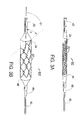
- FIG. 1A shows an artery with a side branch, (i.e., a bifurcated artery) where a first "prior art” stent 1 has been deployed into the main branch and a second "prior art” stent 2A has been deployed into the side branch leaving the section 3 of the arterial wall at the ostium of the side branch un-stented and therefore unsupported.
- the side branch vessel attaches to the main branch at an acute angle ⁇ that is less than 90°.
- FIG. 1B shows an artery with side branch where a first "prior art” stent 1 has been deployed into the main branch and a second "prior art” stent 2B has been deployed into the side branch.
- the second stent 2B extends part way into the main branch causing the stents to overlap.
- Such an extension of metal into an artery can cause turbulent blood flow that can readily result in subacute thrombosis.
- FIG. 2A is a flat layout view of one embodiment of a cylindrical side branch stent 20.
- the stent 20 has "N" shaped flexible connecting links 25.
- the stent 20 is shown in its crimped pre-deployed state as it would appear if it were cut longitudinally and then laid out into a flat, 2-dimensional configuration. It should be clearly understood that the stent 20 is in fact cylindrical in shape, which cylindrical shape would be obtained by rolling the flat configuration of FIG. 2A into a cylinder with the top points "G" joined to the bottom points "H".
- the stent 20 comprises a multiplicity of centrally located, longitudinally separated, circumferential sets of strut members 21 and distal end and proximal end sets of strut members 22 and 24 respectively.
- Each set of strut members 21, 22, or 24 is a cylindrical, closed, zig-zag, ring-like section of the stent 20 consisting of a multiplicity of curved sections 28 connected to diagonal sections 26. Except at the distal and proximal ends of the stent 20, every curved section 28 is attached to a flexible "N" link 25. Such an attachment makes the stent 20 classified as a "closed cell” or "fully-connected" stent.
- the unique feature of the stent 20 that makes it well suited for placement into the ostium of a side branch vessel is the angulation of the most proximal set of strut members 24.
- the set of strut members 24 is angulated with a longitudinal distance "L" between the outside of the most proximal curved section 23 of the set of strut members 24 and the outside of the most distal curved section 27 of the proximal set of strut members 24.
- the set of strut members 24 is cylindrical in nature, this allows for alignment of the set of strut members 24 with the angulated ostium of a side branch vessel.
- the side branch stent 20 will be well suited for vessels with an angle ⁇ at nearly 90° to the main branch. As “L” increases, the stent 20 becomes well suited for side branch vessels that are at angles ⁇ less than 90°.
- the present invention is most applicable to angles between 10 and 80° and might be produced with angles of 15, 30, 45, 60 and 75° to meet the needs of most bifurcated arteries of a human body.
- the stent 20 is typically fabricated by laser machining of a cylindrical, thin-walled, metal tube.
- the stent 20 would be formed from or coated with a highly radiopaque material so that the angulated set of strut members 24 can be visualized for alignment with the ostium of the side branch before deployment of the stent. If the entire stent 20 is not formed from a radiopaque metal, then at least the most proximal set of strut members 24 should be made from a highly radiopaque metal. For example, a stent with a gold coating to produce a more radiopaque end set of strut members as disclosed in US-6086604 could be used for the side branch stent.
- FIG. 2B is a flat layout view of a second embodiment of the present invention stent 30.
- the stent 30 has straight links 35 connecting the sets of strut members, but not on every curved section 38.
- the stent 30 comprises a multiplicity of centrally located, longitudinally separated, sets of strut members 31 and distal end and proximal end sets of strut members 32 and 34 respectively.
- the sets of strut members 31, 32 and 34 are connected to each other by longitudinally extending straight links 35.
- Each set of strut members 31, 32, or 34 is a cylindrical, closed, zig-zag, ring-like section of the stent 30 consisting of a multiplicity of curved sections 38 connected to diagonal sections 36.
- the stent 30 In the centre of the stent 30, not all of the curved sections 38 are attached to a straight connecting links 35. Such an attachment makes the stent 30 classified as an "open cell" stent or a stent that is not “fully connected”.
- the unique feature of the stent 30 making it well suited for placement into the ostium of a side branch is the shape of the most proximal set of strut members 34. Unlike the set of strut members 32 at the distal end of the stent 30, the set of strut members 34 is angulated like the set of strut members 24 of the stent 20 of FIG. 2A. As the set of strut members 34 is cylindrical in nature, this allows for alignment of the proximal set of strut members 34 with the angulated ostium of a side branch vessel.
- FIGS. 2B and 2C illustrate a radiopaque marker 33 placed into a marker holder 41 attached to the most proximal curved section 37 of the proximal set of strut members 34.
- the radiopaque marker 33 allows for better visualization of the most proximal side of the angulated set of strut members 34 and also provides the implanting clinician with an indication of the correct rotational position for the stent 30 at the ostium of the side branch. This feature also allows the stent 30 to be made from a less radiopaque material such as Nitinol or stainless steel.
- a marker could be attached to the most proximal set of strut members 34.
- one marker would be attached to the most proximal of the curved sections 37 of the end set of strut members 34 and a second marker would be attached to the least proximal of the proximal curved sections 39. The use of two such markers would assist the implanting clinician in accurately placing the side branch stent into the ostium of a side branch.
- FIG. 2D is a flat layout view of a third embodiment of the present invention stent 70.
- the stent 70 comprises a multiplicity of centrally located, longitudinally separated, sets of strut members 71 and distal end and proximal end sets of strut members 72 and 74 respectively.
- Each set of strut members 71, 72, or 74 is a cylindrical, closed, zig-zag, ring-like section of the stent 70 consisting of a multiplicity of curved sections 78 connected to diagonal sections 76. Except at the distal and proximal ends of the stent 20, every curved section 28 is attached to a flexible "N" link 75.
- Such an attachment makes the stent 70 classified as a "closed cell” or "fully connected” stent.
- the stent 70 is very similar to the stent 20 of FIG. 2A with the difference being in the greater width "W"' of the diagonal sections 73 of the most proximal set of strut members 74 as compared to the width "W" of the other diagonal sections 76. This increased width of the diagonal sections 73 will make the most proximal angulated set of strut members 74 more visible and improve the ability to align it properly with the plane of the ostium of a side branch.
- FIG. 3A is a sketch of a distal potion of the stent delivery catheter for the side branch stent 20 mounted on a stent delivery catheter 60.
- the stent 20 is mounted onto a balloon 44 attached to distal shaft 46 and proximal shaft 42 of the stent delivery catheter 60.
- a guide wire 50 is also shown in FIG. 3A.
- the most proximal set of strut members 24 is seen with its angulated shape such that the stent delivery catheter 60 must be rotated during stent delivery to align the set of strut members 24 with the ostium of a side branch.
- FIG. 3A can represent any of the three types of stent delivery catheters; namely: (1) a fixed wire, (2) over-the-wire or (3) rapid exchange type stent delivery catheter system.
- the guide wire 50 would be slideable through a lumen in the shaft 46 that extends from the distal end of the shaft 46 to the proximal end of the system 60 as is well known for over-the-wire balloon angioplasty catheters.
- the guide wire 50 would be slideable through a lumen in the shaft 46 that extends from the distal end of the shaft 46 to a location between the proximal end of the balloon 44 and the proximal end of the catheter 60.
- the guide wire 50 In a fixed wire system, the guide wire 50 would be permanently attached to the shaft 46 as disclosed in US patent application no. 09/444104.
- FIG. 3B is a sketch of the present invention stent 20' as radially expanded by the inflated balloon 44' of the stent delivery catheter 60'.
- the expanded most proximal set of strut members 24' forms an angulation angle ⁇ with the longitudinal axis 61 of the stent 20'.
- a side branch stent 20 should have the angulation angle ⁇ that is approximately equal to the angle ⁇ of the side branch as shown in FIGS. 1A and 1B. Having these two angles within ⁇ 15° can provide for good support of the arterial wall at the ostium of an arterial side branch.
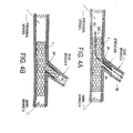
- FIG. 4A is a cross section of an artery with a side branch where a first stent 1 has been placed into the proximal vessel and main branch of a bifurcated artery and the stent delivery catheter 60 of FIG. 3A has been advanced over the guide wire 50 through the struts of the stent 1 into a stenosed side branch.
- the proximal end (not shown) of the shaft 42 of the stent delivery catheter 60 (which proximal end is situated outside the body) is rotated by the physician until the most proximal set of strut members 24 of the stent 20 is aligned with the plane of the ostium of the side branch.
- the stent 20 is then deployed and the balloon catheter 60 is removed from the body.
- FIG. 4B The result of the deployment is shown in FIG. 4B.
- the angulation of the most proximal set of strut members 24' of the deployed stent 20' allows the stent 20' to support the arterial wall at the ostium of the side branch without leaving an un-stented region and without having part of the stent 21' extend into the main branch.
- FIGS. 1A and 1B the shortcomings of prior art stents as illustrated by FIGS. 1A and 1B is overcome by the improved performance of the present invention.
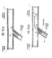
- FIG. 5A is a cross section of an artery with a side branch where the stent delivery catheter 60 and guide wire 50 have been advanced into a stenosed side branch prior to stent deployment.
- the proximal end (not shown) of the shaft 42 of the stent delivery catheter 60 is rotated by the clinician until the plane of the most proximal set of strut members 24 of the stent 20 is approximately aligned with the plane of the ostium of the side branch.
- the stent 20 is then deployed and the balloon catheter 60 is removed from the body.
- FIG. 5B The result of the stent deployment is shown in FIG. 5B.
- the angulation of the most proximal set of strut members 24' of the deployed stent 20' allows the stent 20' to support the arterial wall at the ostium of the side branch without leaving an un-stented region and without extending into the main branch of the artery.
- a self-expanding stent having an angulated most proximal set of strut members can also be produced and deployed at the ostium of a side branch.
- Such a self-expanding stent could be made from Nitinol with one or more radiopaque markings.
Abstract
Description
- This invention is in the field of stents, that are used to maintain patency of a vessel of the human body.
- It has been shown that intravascular stents are an excellent means to maintain the patency of blood vessels following balloon angioplasty. As stent technology has advanced, more and more complex anatomy has been treatable with stents. A particularly difficult anatomy to treat is that of a bifurcation in a blood vessel at the ostium of a side branch.
- A stent system for bifurcations is disclosed in US-5749825 which has two guide wire lumens allowing the deployment of a stent in the first blood vessel while leaving a guide wire positioned through the stent struts into the second vessel which is a side branch.
- This system required several modifications for universal use. First, by needing two guidewires, the profile (outside diameter) of the stenting system is significantly larger as compared to a stent delivery catheter that uses a single guide wire. Second, the known design does not address placing a stent into the second branch across the ostium, which is often not at a 90° angle to the first vessel.
- A bifurcation stent delivery catheter with two distal balloons and one stent segment for each of the two vessels would give the capability of stenting the second branch vessel, but such a device would be larger in profile and harder to deliver than the known device referred to above. If one places a first stent into a main artery with that stent being positioned across the ostium of the side branch, and the side branch is not at a 90° angle to the main branch, then either the second stent will extend into the main branch of the artery or some portion of the arterial wall at the ostium will not be properly supported by the second stent.
- Most current tubular stents use a multiplicity of circumferential sets of strut members connected by either straight longitudinal connecting links or undulating longitudinal flexible links. The circumferential sets of strut members typically are formed from a series of diagonal sections connected to curved sections, so as to form a circumferential, closed-ring, zig-zag structure. This structure opens up as the stent expands to form the elements of the stent that provide structural support for the arterial wall. A "single strut" member is defined for use herein as a diagonal section connected to a curved section within one of the circumferential sets of strut members.
- The terms "side branch" and "bifurcation" will be used interchangeably throughout this specification.
- It is highly desirable after placing a first stent into the "main branch" of an artery and inserting a guide wire through the side of the expanded stent and into a side branch, to be able to place a stent across the ostium of the angled side branch (or bifurcation) where the second stent provides support to scaffold the arterial wall at the ostium of the side branch without having the stent extend into the main branch. The present invention uses sets of strut members where the most distal set of strut members is similar to that of most stents in that the plane of the distal set of strut members is perpendicular to the stent's longitudinal axis. The present invention has a multiplicity of circumferential sets of strut members, but only the distal set of strut members has its plane perpendicular to the stent's longitudinal axis. The more proximal sets of strut members are angulated, so that the plane of the most proximal set of strut members has a preset angle such as 30°, 45° or 60° relative to the stent's longitudinal axis. The stent could also be formed from or coated with a highly radiopaque material. Alternately, a radiopaque marker could be placed at the most proximal point of the angulated, side branch stent, for the stent has to be rotated by the clinician until the plane of the most proximal angulated set of strut members is situated to be approximately parallel to the plane of the ostium of the side branch. It is also envisioned to widen the diagonal sections of the most proximal circumferential set of strut members to increase their radiopacity as compared to the radiopacity of the more distal circumferential sets of strut members. This can assist the clinician who places the side branch stent to have it properly placed at the ostium of the side branch.
- The clinician first determines the angle that the side branch makes with the main artery to which it is connected. The clinician then selects an angulated side branch stent that most closely matches that angle. For example, if the side branch makes an angle of 40° with the main artery, the clinician might select a side branch stent having an angle of 45° between the plane of the most proximal set of strut members and the stent's longitudinal axis. Then, after placing a first stent into a main artery, the clinician would place a guide wire through the side of the expanded stent in the artery's main branch and advance the guide wire into the side branch. If necessary, the clinician might use a balloon of a balloon angioplasty catheter to open the struts of the first stent to "un-jail" the ostium of the side branch. The present invention stent would then be inserted over a guide wire that has been advanced through the struts of the first stent and into the side branch. The present invention stent would then be rotated until the plane of the most proximal angulated set of strut members is parallel to the plane of the ostium of the side branch. The present invention stent would then inflated across the ostium of the side branch providing good scaffolding because of the angulated struts which are the most proximal set of strut members of the side branch stent.
- A key to rotatability of the present invention is in the design of the stent delivery catheter. The stent delivery catheter must be highly torqueable by the clinician, i.e., there must be a close to one-to-one correlation between how the clinician rotates the proximal end of the stent delivery catheter and how the distal portion including the stent rotates. The present invention envisions modifications of both over-the-wire and rapid exchange stent delivery catheters to provide enhanced torqueability for proper rotation and alignment of the angulated stent into a side branch.
- A stent delivery catheter with a fixed guide wire is disclosed in US patent application no. 09/444,104 entitled "Stent Delivery Catheter With a Fixed Guide Wire". This stent delivery catheter is designed to be highly torqueable to allow for proper steering of the fixed guide wire. It is certainly envisioned that the system described in the fixed wire stent patent application can be used for the side branch stent as described herein.
- A balloon angioplasty catheter with a rapid exchange tip is disclosed in US-5830227. This device, when combined with the more proximal portions of the stent delivery catheter with fixed wires could be both low profile and provide for good delivery of a side branch stent. It is also envisioned that a standard over-the-wire balloon angioplasty catheter with enhanced torqueability can be produced that would also serve to rotate into position and properly deliver the side branch stent that is described herein.
- The present invention stent may have one or more standard circumferential sets of strut members at the distal end of the stent and an angulated set of strut members at the proximal end of the stent. To keep the stent cell size small it may be desirable to have the most proximal set of strut members be the most angulated, with each successive set of strut members as taken in the distal direction becoming less angulated, until the plane of the most distal set of strut members is perpendicular to the stent's longitudinal axis.
- The present invention stent delivery catheter may include a non-compliant balloon mounted on a catheter shaft with enhanced torqueability. It is also clear that if the main branch of an artery is essentially free of plaque build-up and only a side branch with an angled ostium is stenosed, then the present invention stent would be ideally suited for elective stenting of the side branch without prior stenting of the main branch. An example of such a use is for stenting at the ostium of a renal artery where it joins the aorta.
- Thus it is an object of this invention to have a stent with its most proximal set of strut members being generally in a plane that is angulated and not perpendicular to the stent's longitudinal axis.
- Another object of this invention is to have more than one angulated set of strut members near the proximal end of the stent.
- Still another object of this invention is to have the most distal set of strut members be a standard "open slot" set of strut members with the plane of the distal set of strut members being perpendicular to the stent's longitudinal axis.
- Still another object of this invention is to have the plane of the angulated sets of strut members change in angle with respect to the stent's longitudinal axis with the most angulated set of strut members being at the proximal end of the stent.
- Still another object of this invention is to have at least one radiopaque marker to indicate the position of the most proximal strut of the angulated stent in order to provide the clinician with a clear indication of the correct rotational alignment of the stent at the ostium of a side branch.
- Still another object of this invention is to have enhanced radiopacity for the most proximal angulated circumferential set of strut members to assist the clinician in rotating the side branch stent to make the plane of the most proximal set of strut members to be situated approximately parallel to the plane of the ostium of the side branch.
- Still another object of this invention is to have a method for stenting at the ostium of a side branch comprising: first stenting the main branch, then placing a guide wire through the first stent's struts into the side branch; dilating with a balloon catheter to unjail the ostium of the side branch; inserting the present invention stent mounted on a balloon into the side branch; rotating the side branch stent until the plane of the most proximal set of strut members is approximately parallel to the plane of the ostium of the side branch and then deploying the side branch stent.
- Still another object of the present invention is to have a stent delivery catheter for side branch stenting having a catheter shaft with enhanced torqueability.
- Still another object of the present invention is to have a fixed wire stent delivery catheter that includes a side branch stent.
- Still another object of the present invention is to have a self-expanding stent having its most proximal set of strut members having a plane that is angulated relative to the stent's longitudinal axis thereby being adapted for deployment at the ostium of a side branch.
- This invention will now be described by way of example with reference to the accompanying drawings, in which:
- FIG. 1A is cross section of the prior art showing an artery with a side branch where a first stent is placed into the main branch and a second stent is placed into a side branch leaving part of the wall of the side branch unsupported.
- FIG. 1B is a cross section of the prior art showing an artery with a side branch where a first stent is placed in the main branch and a second stent is placed into a side branch where a proximal portion of the second stent extends part way into the main branch.
- FIG. 2A is a layout view of one embodiment of the present invention stent.
- FIG. 2B is a layout view of a second embodiment of the present invention stent.
- FIG. 2C is an enlargement of the radiopaque marker of FIG. 2B.
- FIG. 2D is a layout view of a third embodiment of the present invention stent.
- FIG. 3A illustrates a distal portion of a stent delivery catheter having the present invention (which is a side branch stent) mounted onto that catheter.
- FIG. 3B illustrates the present invention stent expanded by the balloon of its stent delivery catheter.
- FIG. 4A is a cross section of an artery with a side branch where a first stent has placed in the main branch and the present invention stent is advanced on its stent delivery catheter before being deployed into the side branch.
- FIG. 4B is a cross section of an artery with a side branch where a first stent has been placed in the main branch and the present invention stent has been deployed in the side branch.
- FIG. 5A is a cross section of a stent delivery catheter having a side branch stent about to be placed at the ostium of an arterial side branch.
- FIG. 5B is a cross section of the side branch stent of FIG. 5A as it is deployed into the side branch.
-
- Referring to the drawings, FIG. 1A shows an artery with a side branch, (i.e., a bifurcated artery) where a first "prior art"
stent 1 has been deployed into the main branch and a second "prior art" stent 2A has been deployed into the side branch leaving the section 3 of the arterial wall at the ostium of the side branch un-stented and therefore unsupported. The side branch vessel attaches to the main branch at an acute angle Φ that is less than 90°. An angle Φ=90° would be a perpendicular attachment. - FIG. 1B shows an artery with side branch where a first "prior art"
stent 1 has been deployed into the main branch and a second "prior art"stent 2B has been deployed into the side branch. In FIG. 1B, thesecond stent 2B extends part way into the main branch causing the stents to overlap. Such an extension of metal into an artery can cause turbulent blood flow that can readily result in subacute thrombosis. - FIG. 2A is a flat layout view of one embodiment of a cylindrical
side branch stent 20. Thestent 20 has "N" shaped flexible connectinglinks 25. Thestent 20 is shown in its crimped pre-deployed state as it would appear if it were cut longitudinally and then laid out into a flat, 2-dimensional configuration. It should be clearly understood that thestent 20 is in fact cylindrical in shape, which cylindrical shape would be obtained by rolling the flat configuration of FIG. 2A into a cylinder with the top points "G" joined to the bottom points "H". - The
stent 20 comprises a multiplicity of centrally located, longitudinally separated, circumferential sets ofstrut members 21 and distal end and proximal end sets ofstrut members strut members stent 20 consisting of a multiplicity of curved sections 28 connected todiagonal sections 26. Except at the distal and proximal ends of thestent 20, every curved section 28 is attached to a flexible "N"link 25. Such an attachment makes thestent 20 classified as a "closed cell" or "fully-connected" stent. The unique feature of thestent 20 that makes it well suited for placement into the ostium of a side branch vessel is the angulation of the most proximal set ofstrut members 24. Unlike the set ofstrut members 22 at the distal end of thestent 20, the set ofstrut members 24 is angulated with a longitudinal distance "L" between the outside of the most proximalcurved section 23 of the set ofstrut members 24 and the outside of the most distalcurved section 27 of the proximal set ofstrut members 24. As the set ofstrut members 24 is cylindrical in nature, this allows for alignment of the set ofstrut members 24 with the angulated ostium of a side branch vessel. If "L" is relatively small, then theside branch stent 20 will be well suited for vessels with an angle Φ at nearly 90° to the main branch. As "L" increases, thestent 20 becomes well suited for side branch vessels that are at angles less than 90°. One can envision a set of side branch stent products having three key dimensions, length, diameter and angle. For 90°, a prior art stent will suffice, for nearly 0° (a bifurcation that is essentially parallel to the main branch), three prior art stents can be used with one placed in the main branch before the bifurcation and one in each leg of a bifurcation. The present invention is most applicable to angles between 10 and 80° and might be produced with angles of 15, 30, 45, 60 and 75° to meet the needs of most bifurcated arteries of a human body. - The
stent 20 is typically fabricated by laser machining of a cylindrical, thin-walled, metal tube. Thestent 20 would be formed from or coated with a highly radiopaque material so that the angulated set ofstrut members 24 can be visualized for alignment with the ostium of the side branch before deployment of the stent. If theentire stent 20 is not formed from a radiopaque metal, then at least the most proximal set ofstrut members 24 should be made from a highly radiopaque metal. For example, a stent with a gold coating to produce a more radiopaque end set of strut members as disclosed in US-6086604 could be used for the side branch stent. - FIG. 2B is a flat layout view of a second embodiment of the present invention stent 30. The stent 30 has straight links 35 connecting the sets of strut members, but not on every
curved section 38. The stent 30 comprises a multiplicity of centrally located, longitudinally separated, sets of strut members 31 and distal end and proximal end sets ofstrut members strut members strut members curved sections 38 connected todiagonal sections 36. In the centre of the stent 30, not all of thecurved sections 38 are attached to a straight connecting links 35. Such an attachment makes the stent 30 classified as an "open cell" stent or a stent that is not "fully connected". The unique feature of the stent 30 making it well suited for placement into the ostium of a side branch is the shape of the most proximal set ofstrut members 34. Unlike the set ofstrut members 32 at the distal end of the stent 30, the set ofstrut members 34 is angulated like the set ofstrut members 24 of thestent 20 of FIG. 2A. As the set ofstrut members 34 is cylindrical in nature, this allows for alignment of the proximal set ofstrut members 34 with the angulated ostium of a side branch vessel. - FIGS. 2B and 2C illustrate a
radiopaque marker 33 placed into amarker holder 41 attached to the most proximalcurved section 37 of the proximal set ofstrut members 34. Theradiopaque marker 33 allows for better visualization of the most proximal side of the angulated set ofstrut members 34 and also provides the implanting clinician with an indication of the correct rotational position for the stent 30 at the ostium of the side branch. This feature also allows the stent 30 to be made from a less radiopaque material such as Nitinol or stainless steel. - It is also envisioned that more than one such marker could be attached to the most proximal set of
strut members 34. Ideally, one marker would be attached to the most proximal of thecurved sections 37 of the end set ofstrut members 34 and a second marker would be attached to the least proximal of the proximalcurved sections 39. The use of two such markers would assist the implanting clinician in accurately placing the side branch stent into the ostium of a side branch. - FIG. 2D is a flat layout view of a third embodiment of the
present invention stent 70. Thestent 70 comprises a multiplicity of centrally located, longitudinally separated, sets ofstrut members 71 and distal end and proximal end sets ofstrut members strut members stent 70 consisting of a multiplicity ofcurved sections 78 connected todiagonal sections 76. Except at the distal and proximal ends of thestent 20, every curved section 28 is attached to a flexible "N"link 75. Such an attachment makes thestent 70 classified as a "closed cell" or "fully connected" stent. Thestent 70 is very similar to thestent 20 of FIG. 2A with the difference being in the greater width "W"' of thediagonal sections 73 of the most proximal set ofstrut members 74 as compared to the width "W" of the otherdiagonal sections 76. This increased width of thediagonal sections 73 will make the most proximal angulated set ofstrut members 74 more visible and improve the ability to align it properly with the plane of the ostium of a side branch. - FIG. 3A is a sketch of a distal potion of the stent delivery catheter for the
side branch stent 20 mounted on astent delivery catheter 60. Thestent 20 is mounted onto aballoon 44 attached todistal shaft 46 andproximal shaft 42 of thestent delivery catheter 60. Aguide wire 50 is also shown in FIG. 3A. The most proximal set ofstrut members 24 is seen with its angulated shape such that thestent delivery catheter 60 must be rotated during stent delivery to align the set ofstrut members 24 with the ostium of a side branch. - FIG. 3A can represent any of the three types of stent delivery catheters; namely: (1) a fixed wire, (2) over-the-wire or (3) rapid exchange type stent delivery catheter system. In an over-the-wire system, the
guide wire 50 would be slideable through a lumen in theshaft 46 that extends from the distal end of theshaft 46 to the proximal end of thesystem 60 as is well known for over-the-wire balloon angioplasty catheters. In a rapid exchange system, theguide wire 50 would be slideable through a lumen in theshaft 46 that extends from the distal end of theshaft 46 to a location between the proximal end of theballoon 44 and the proximal end of thecatheter 60. In a fixed wire system, theguide wire 50 would be permanently attached to theshaft 46 as disclosed in US patent application no. 09/444104. - FIG. 3B is a sketch of the present invention stent 20' as radially expanded by the inflated balloon 44' of the stent delivery catheter 60'. The expanded most proximal set of strut members 24' forms an angulation angle α with the
longitudinal axis 61 of the stent 20'. Ideally, aside branch stent 20 should have the angulation angle α that is approximately equal to the angle Φ of the side branch as shown in FIGS. 1A and 1B. Having these two angles within ±15° can provide for good support of the arterial wall at the ostium of an arterial side branch. - FIG. 4A is a cross section of an artery with a side branch where a
first stent 1 has been placed into the proximal vessel and main branch of a bifurcated artery and thestent delivery catheter 60 of FIG. 3A has been advanced over theguide wire 50 through the struts of thestent 1 into a stenosed side branch. Once thestent 20 has been pushed through the struts of thestent 1, the proximal end (not shown) of theshaft 42 of the stent delivery catheter 60 (which proximal end is situated outside the body) is rotated by the physician until the most proximal set ofstrut members 24 of thestent 20 is aligned with the plane of the ostium of the side branch. Thestent 20 is then deployed and theballoon catheter 60 is removed from the body. - The result of the deployment is shown in FIG. 4B. The angulation of the most proximal set of strut members 24' of the deployed stent 20', allows the stent 20' to support the arterial wall at the ostium of the side branch without leaving an un-stented region and without having part of the stent 21' extend into the main branch. Thus the shortcomings of prior art stents as illustrated by FIGS. 1A and 1B is overcome by the improved performance of the present invention.
- FIG. 5A is a cross section of an artery with a side branch where the
stent delivery catheter 60 andguide wire 50 have been advanced into a stenosed side branch prior to stent deployment. Once thestent 20 has been pushed into the side branch, the proximal end (not shown) of theshaft 42 of thestent delivery catheter 60 is rotated by the clinician until the plane of the most proximal set ofstrut members 24 of thestent 20 is approximately aligned with the plane of the ostium of the side branch. Thestent 20 is then deployed and theballoon catheter 60 is removed from the body. - The result of the stent deployment is shown in FIG. 5B. The angulation of the most proximal set of strut members 24' of the deployed stent 20' allows the stent 20' to support the arterial wall at the ostium of the side branch without leaving an un-stented region and without extending into the main branch of the artery.
- Although the descriptions herein have concentrated on application of the present invention to balloon expandable stents, it is also envisioned that a self-expanding stent having an angulated most proximal set of strut members can also be produced and deployed at the ostium of a side branch. Such a self-expanding stent could be made from Nitinol with one or more radiopaque markings.
Claims (12)
- A stent comprising:a thin-walled, multi-cellular, tubular structure having a longitudinal axis, a proximal end and a distal end; a multiplicity of circumferential sets of strut members, longitudinally separated each from the other and each set of strut members forming a closed, cylindrical portion of the stent, the stent also having a proximal set of strut members located at the proximal end of the stent, a distal set of strut members located at the distal end of the stent and central sets of strut members positioned between the proximal and distal sets of strut members, the plane of the most proximal set of strut members having an angulation between 15 and 75 ° with respect to the longitudinal axis of the stent when the stent has been expanded within a vessel of the human body and the plane of the proximal distal and central sets of strut members differing from one another.
- The stent of claim 1 wherein the stent is self-expanding.
- The stent of claim 1 wherein the stent is balloon expandable.
- The stent of claim 1 wherein the stent is mounted on a fixed-wire stent delivery catheter.
- The stent of claim 1 wherein the stent is mounted on an over-the-wire stent delivery catheter.
- The stent of claim 1 wherein the stent is mounted on a rapid exchange stent delivery catheter.
- The stent of claim 1 wherein the entire stent is formed from a radiopaque metal, preferably tantalum.
- The stent of claim 1 wherein the stent is coated with a radiopaque metal, preferably gold.
- The stent of claim 1 wherein the proximal set of strut members is coated with a radiopaque metal, preferably gold.
- The stent of claim 1 wherein a radiopaque marker is attached to one of (a) the most proximal location on the most proximal set of strut members, and (b) the most distal location on the most proximal set of strut members.
- The stent of claim 1 wherein diagonal sections of the proximal set of strut members have a greater average width than the width of diagonal sections of the central sets of strut members.
- The stent of claim 1 wherein the sets of strut members are connected each to the other by at least one of (a) by longitudinally extending flexible links having an undulating shape, and (b) longitudinally extending straight links.
Applications Claiming Priority (2)
| Application Number | Priority Date | Filing Date | Title |
|---|---|---|---|
| US09/950,956 US7252679B2 (en) | 2001-09-13 | 2001-09-13 | Stent with angulated struts |
| US950956 | 2001-09-13 |
Publications (2)
| Publication Number | Publication Date |
|---|---|
| EP1293178A2 true EP1293178A2 (en) | 2003-03-19 |
| EP1293178A3 EP1293178A3 (en) | 2004-01-14 |
Family
ID=25491086
Family Applications (1)
| Application Number | Title | Priority Date | Filing Date |
|---|---|---|---|
| EP02256355A Withdrawn EP1293178A3 (en) | 2001-09-13 | 2002-09-13 | Stent with angulated struts |
Country Status (3)
| Country | Link |
|---|---|
| US (1) | US7252679B2 (en) |
| EP (1) | EP1293178A3 (en) |
| CA (1) | CA2402818C (en) |
Cited By (9)
| Publication number | Priority date | Publication date | Assignee | Title |
|---|---|---|---|---|
| EP1472991A2 (en) * | 2003-04-25 | 2004-11-03 | Medtronic Vascular, Inc. | Bifurcated stent with concentric body portions |
| EP1512381A2 (en) * | 2003-09-03 | 2005-03-09 | Cordis Corporation | Side branch stent with split proximal end |
| FR2870716A1 (en) * | 2004-05-27 | 2005-12-02 | Francis Besse | Endovascular stent for treating blood circulation disorders of e.g. human, has ends with one end being beveled according to predetermined angle which is defined as angle between bevel plane and section plane of stent |
| WO2006024488A2 (en) | 2004-08-30 | 2006-03-09 | Interstitial Therapeutics | Medical stent provided with inhibitors of atp synthesis |
| WO2007104051A2 (en) * | 2006-03-09 | 2007-09-13 | Abbott Laboratories | Stent having contoured proximal end |
| EP2073767A1 (en) * | 2006-09-25 | 2009-07-01 | Alexander Grigorievich Viller | Self-expandable stent systems for bifurcated lesions |
| US7654264B2 (en) | 2006-07-18 | 2010-02-02 | Nellcor Puritan Bennett Llc | Medical tube including an inflatable cuff having a notched collar |
| US8167929B2 (en) | 2006-03-09 | 2012-05-01 | Abbott Laboratories | System and method for delivering a stent to a bifurcated vessel |
| US9402754B2 (en) | 2010-05-18 | 2016-08-02 | Abbott Cardiovascular Systems, Inc. | Expandable endoprostheses, systems, and methods for treating a bifurcated lumen |
Families Citing this family (191)
| Publication number | Priority date | Publication date | Assignee | Title |
|---|---|---|---|---|
| US7591846B2 (en) | 1996-11-04 | 2009-09-22 | Boston Scientific Scimed, Inc. | Methods for deploying stents in bifurcations |
| US6835203B1 (en) | 1996-11-04 | 2004-12-28 | Advanced Stent Technologies, Inc. | Extendible stent apparatus |
| US8211167B2 (en) | 1999-12-06 | 2012-07-03 | Boston Scientific Scimed, Inc. | Method of using a catheter with attached flexible side sheath |
| US6692483B2 (en) | 1996-11-04 | 2004-02-17 | Advanced Stent Technologies, Inc. | Catheter with attached flexible side sheath |
| US7220275B2 (en) * | 1996-11-04 | 2007-05-22 | Advanced Stent Technologies, Inc. | Stent with protruding branch portion for bifurcated vessels |
| US7341598B2 (en) | 1999-01-13 | 2008-03-11 | Boston Scientific Scimed, Inc. | Stent with protruding branch portion for bifurcated vessels |
| US6599316B2 (en) | 1996-11-04 | 2003-07-29 | Advanced Stent Technologies, Inc. | Extendible stent apparatus |
| ATE539702T1 (en) * | 1996-11-04 | 2012-01-15 | Advanced Stent Tech Inc | DEVICE FOR EXPANDING A STENT AND METHOD FOR DEPLOYING IT |
| US6325826B1 (en) | 1998-01-14 | 2001-12-04 | Advanced Stent Technologies, Inc. | Extendible stent apparatus |
| US8257425B2 (en) * | 1999-01-13 | 2012-09-04 | Boston Scientific Scimed, Inc. | Stent with protruding branch portion for bifurcated vessels |
| US7655030B2 (en) | 2003-07-18 | 2010-02-02 | Boston Scientific Scimed, Inc. | Catheter balloon systems and methods |
| US20050060027A1 (en) * | 1999-01-13 | 2005-03-17 | Advanced Stent Technologies, Inc. | Catheter balloon systems and methods |
| DE60021173T2 (en) * | 1999-01-27 | 2006-04-27 | Boston Scientific Ltd., St Michael | BIFURKATIONSSTENTEINFÜHRSYSTEM |
| EP1229859A2 (en) * | 1999-09-23 | 2002-08-14 | Advanced Stent Technologies, Inc. | Bifurcation stent system and method |
| US6689156B1 (en) * | 1999-09-23 | 2004-02-10 | Advanced Stent Technologies, Inc. | Stent range transducers and methods of use |
| US7101391B2 (en) * | 2000-09-18 | 2006-09-05 | Inflow Dynamics Inc. | Primarily niobium stent |
| AU2002250189A1 (en) | 2001-02-26 | 2002-09-12 | Scimed Life Systems, Inc. | Bifurcated stent and delivery system |
| US8617231B2 (en) | 2001-05-18 | 2013-12-31 | Boston Scientific Scimed, Inc. | Dual guidewire exchange catheter system |
| US7756583B2 (en) | 2002-04-08 | 2010-07-13 | Ardian, Inc. | Methods and apparatus for intravascularly-induced neuromodulation |
| US7853333B2 (en) | 2002-04-08 | 2010-12-14 | Ardian, Inc. | Methods and apparatus for multi-vessel renal neuromodulation |
| US7653438B2 (en) | 2002-04-08 | 2010-01-26 | Ardian, Inc. | Methods and apparatus for renal neuromodulation |
| US8347891B2 (en) | 2002-04-08 | 2013-01-08 | Medtronic Ardian Luxembourg S.A.R.L. | Methods and apparatus for performing a non-continuous circumferential treatment of a body lumen |
| US20050065596A1 (en) * | 2002-07-24 | 2005-03-24 | Xufan Tseng | Stents capable of controllably releasing histone deacetylase inhibitors |
| US8298280B2 (en) | 2003-08-21 | 2012-10-30 | Boston Scientific Scimed, Inc. | Stent with protruding branch portion for bifurcated vessels |
| EP3045136B1 (en) | 2003-09-12 | 2021-02-24 | Vessix Vascular, Inc. | Selectable eccentric remodeling and/or ablation of atherosclerotic material |
| US7344557B2 (en) * | 2003-11-12 | 2008-03-18 | Advanced Stent Technologies, Inc. | Catheter balloon systems and methods |
| US7780715B2 (en) * | 2004-03-04 | 2010-08-24 | Y Med, Inc. | Vessel treatment devices |
| US7753951B2 (en) * | 2004-03-04 | 2010-07-13 | Y Med, Inc. | Vessel treatment devices |
| US7766951B2 (en) | 2004-03-04 | 2010-08-03 | Y Med, Inc. | Vessel treatment devices |
| US9050437B2 (en) * | 2004-03-04 | 2015-06-09 | YMED, Inc. | Positioning device for ostial lesions |
| US8007528B2 (en) * | 2004-03-17 | 2011-08-30 | Boston Scientific Scimed, Inc. | Bifurcated stent |
| JP5054524B2 (en) | 2004-06-08 | 2012-10-24 | アドバンスド ステント テクノロジーズ, インコーポレイテッド | Stent with protruding branch for branch pipe |
| US8920414B2 (en) | 2004-09-10 | 2014-12-30 | Vessix Vascular, Inc. | Tuned RF energy and electrical tissue characterization for selective treatment of target tissues |
| US8396548B2 (en) | 2008-11-14 | 2013-03-12 | Vessix Vascular, Inc. | Selective drug delivery in a lumen |
| US9713730B2 (en) | 2004-09-10 | 2017-07-25 | Boston Scientific Scimed, Inc. | Apparatus and method for treatment of in-stent restenosis |
| US9427340B2 (en) * | 2004-12-14 | 2016-08-30 | Boston Scientific Scimed, Inc. | Stent with protruding branch portion for bifurcated vessels |
| FR2881946B1 (en) * | 2005-02-17 | 2008-01-04 | Jacques Seguin | DEVICE FOR THE TREATMENT OF BODILY CONDUIT AT BIFURCATION LEVEL |
| US8480728B2 (en) * | 2005-05-26 | 2013-07-09 | Boston Scientific Scimed, Inc. | Stent side branch deployment initiation geometry |
| US8317855B2 (en) * | 2005-05-26 | 2012-11-27 | Boston Scientific Scimed, Inc. | Crimpable and expandable side branch cell |
| US20060271161A1 (en) * | 2005-05-26 | 2006-11-30 | Boston Scientific Scimed, Inc. | Selective treatment of stent side branch petals |
| US8043366B2 (en) * | 2005-09-08 | 2011-10-25 | Boston Scientific Scimed, Inc. | Overlapping stent |
| US8038706B2 (en) * | 2005-09-08 | 2011-10-18 | Boston Scientific Scimed, Inc. | Crown stent assembly |
| US7731741B2 (en) | 2005-09-08 | 2010-06-08 | Boston Scientific Scimed, Inc. | Inflatable bifurcation stent |
| US20070088428A1 (en) * | 2005-09-15 | 2007-04-19 | Cappella, Inc. | Intraluminal device with asymmetric cap portion |
| US20070061003A1 (en) * | 2005-09-15 | 2007-03-15 | Cappella, Inc. | Segmented ostial protection device |
| US20070112418A1 (en) * | 2005-11-14 | 2007-05-17 | Boston Scientific Scimed, Inc. | Stent with spiral side-branch support designs |
| US8343211B2 (en) * | 2005-12-14 | 2013-01-01 | Boston Scientific Scimed, Inc. | Connectors for bifurcated stent |
| US8435284B2 (en) * | 2005-12-14 | 2013-05-07 | Boston Scientific Scimed, Inc. | Telescoping bifurcated stent |
| US7540881B2 (en) | 2005-12-22 | 2009-06-02 | Boston Scientific Scimed, Inc. | Bifurcation stent pattern |
| US20070156230A1 (en) | 2006-01-04 | 2007-07-05 | Dugan Stephen R | Stents with radiopaque markers |
| US8821561B2 (en) | 2006-02-22 | 2014-09-02 | Boston Scientific Scimed, Inc. | Marker arrangement for bifurcation catheter |
| US20070208419A1 (en) * | 2006-03-06 | 2007-09-06 | Boston Scientific Scimed, Inc. | Bifurcation stent with uniform side branch projection |
| US7833264B2 (en) * | 2006-03-06 | 2010-11-16 | Boston Scientific Scimed, Inc. | Bifurcated stent |
| US20070208411A1 (en) * | 2006-03-06 | 2007-09-06 | Boston Scientific Scimed, Inc. | Bifurcated stent with surface area gradient |
| US8298278B2 (en) * | 2006-03-07 | 2012-10-30 | Boston Scientific Scimed, Inc. | Bifurcated stent with improvement securement |
| US20070233233A1 (en) * | 2006-03-31 | 2007-10-04 | Boston Scientific Scimed, Inc | Tethered expansion columns for controlled stent expansion |
| US8019435B2 (en) | 2006-05-02 | 2011-09-13 | Boston Scientific Scimed, Inc. | Control of arterial smooth muscle tone |
| US7901378B2 (en) * | 2006-05-11 | 2011-03-08 | Y-Med, Inc. | Systems and methods for treating a vessel using focused force |
| US8486025B2 (en) * | 2006-05-11 | 2013-07-16 | Ronald J. Solar | Systems and methods for treating a vessel using focused force |
| US8752268B2 (en) | 2006-05-26 | 2014-06-17 | Abbott Cardiovascular Systems Inc. | Method of making stents with radiopaque markers |
| WO2007140320A2 (en) | 2006-05-26 | 2007-12-06 | Nanyang Technological University | Implantable article, method of forming same and method for reducing thrombogenicity |
| US7922758B2 (en) | 2006-06-23 | 2011-04-12 | Boston Scientific Scimed, Inc. | Nesting twisting hinge points in a bifurcated petal geometry |
| US8216267B2 (en) * | 2006-09-12 | 2012-07-10 | Boston Scientific Scimed, Inc. | Multilayer balloon for bifurcated stent delivery and methods of making and using the same |
| US7951191B2 (en) | 2006-10-10 | 2011-05-31 | Boston Scientific Scimed, Inc. | Bifurcated stent with entire circumferential petal |
| EP2076194B1 (en) | 2006-10-18 | 2013-04-24 | Vessix Vascular, Inc. | System for inducing desirable temperature effects on body tissue |
| EP2992850A1 (en) | 2006-10-18 | 2016-03-09 | Vessix Vascular, Inc. | Inducing desirable temperature effects on body tissue |
| US8206429B2 (en) | 2006-11-02 | 2012-06-26 | Boston Scientific Scimed, Inc. | Adjustable bifurcation catheter incorporating electroactive polymer and methods of making and using the same |
| US7842082B2 (en) | 2006-11-16 | 2010-11-30 | Boston Scientific Scimed, Inc. | Bifurcated stent |
| FR2911063B1 (en) | 2007-01-09 | 2009-03-20 | Stentys S A S Soc Par Actions | RUPTIBLE BRIDGE STRUCTURE FOR STENT, AND STENT INCLUDING SUCH BRIDGE STRUCTURES. |
| US7959668B2 (en) | 2007-01-16 | 2011-06-14 | Boston Scientific Scimed, Inc. | Bifurcated stent |
| US20080177370A1 (en) * | 2007-01-22 | 2008-07-24 | Adam Stys | Device and method for supporting a side branch of a vessel |
| US20080177367A1 (en) * | 2007-01-22 | 2008-07-24 | Adam Stys | Treatment device for treating a side branch of a vessel and method for positioning a stent in a side branch |
| US8118861B2 (en) * | 2007-03-28 | 2012-02-21 | Boston Scientific Scimed, Inc. | Bifurcation stent and balloon assemblies |
| US8647376B2 (en) * | 2007-03-30 | 2014-02-11 | Boston Scientific Scimed, Inc. | Balloon fold design for deployment of bifurcated stent petal architecture |
| US20080300671A1 (en) * | 2007-06-04 | 2008-12-04 | Gil Vardi | Stent having high expansion ratio |
| US8486134B2 (en) | 2007-08-01 | 2013-07-16 | Boston Scientific Scimed, Inc. | Bifurcation treatment system and methods |
| US7959669B2 (en) | 2007-09-12 | 2011-06-14 | Boston Scientific Scimed, Inc. | Bifurcated stent with open ended side branch support |
| US8540758B2 (en) * | 2007-11-27 | 2013-09-24 | Vimal I. Nanavati | Bifurcation stent and delivery system |
| US7833266B2 (en) | 2007-11-28 | 2010-11-16 | Boston Scientific Scimed, Inc. | Bifurcated stent with drug wells for specific ostial, carina, and side branch treatment |
| US8277501B2 (en) | 2007-12-21 | 2012-10-02 | Boston Scientific Scimed, Inc. | Bi-stable bifurcated stent petal geometry |
| US8747456B2 (en) | 2007-12-31 | 2014-06-10 | Boston Scientific Scimed, Inc. | Bifurcation stent delivery system and methods |
| US8932340B2 (en) | 2008-05-29 | 2015-01-13 | Boston Scientific Scimed, Inc. | Bifurcated stent and delivery system |
| US8377108B2 (en) | 2008-06-02 | 2013-02-19 | Boston Scientific Scimed, Inc. | Staggered two balloon bifurcation catheter assembly and methods |
| JP5662310B2 (en) | 2008-06-05 | 2015-01-28 | ボストン サイエンティフィック サイムド,インコーポレイテッドBoston Scientific Scimed,Inc. | Shrinkable branch device and method of manufacturing the same |
| WO2009149405A1 (en) | 2008-06-05 | 2009-12-10 | Boston Scientific Scimed, Inc. | Balloon bifurcated lumen treatment |
| US8206636B2 (en) | 2008-06-20 | 2012-06-26 | Amaranth Medical Pte. | Stent fabrication via tubular casting processes |
| US10898620B2 (en) | 2008-06-20 | 2021-01-26 | Razmodics Llc | Composite stent having multi-axial flexibility and method of manufacture thereof |
| US8206635B2 (en) | 2008-06-20 | 2012-06-26 | Amaranth Medical Pte. | Stent fabrication via tubular casting processes |
| US9005274B2 (en) * | 2008-08-04 | 2015-04-14 | Stentys Sas | Method for treating a body lumen |
| EP2334265B1 (en) * | 2008-09-12 | 2013-06-26 | Alexander Grigorievich Viller | Double-balloon delivery system for an implantable chamfered stent |
| CA2743992A1 (en) | 2008-11-17 | 2010-05-20 | Minnow Medical, Inc. | Selective accumulation of energy with or without knowledge of tissue topography |
| US9309347B2 (en) | 2009-05-20 | 2016-04-12 | Biomedical, Inc. | Bioresorbable thermoset polyester/urethane elastomers |
| US8888840B2 (en) * | 2009-05-20 | 2014-11-18 | Boston Scientific Scimed, Inc. | Drug eluting medical implant |
| US9265633B2 (en) | 2009-05-20 | 2016-02-23 | 480 Biomedical, Inc. | Drug-eluting medical implants |
| US8137396B2 (en) * | 2009-05-20 | 2012-03-20 | 480 Biomedical, Inc | Medical implant |
| US8992601B2 (en) | 2009-05-20 | 2015-03-31 | 480 Biomedical, Inc. | Medical implants |
| US20110319987A1 (en) | 2009-05-20 | 2011-12-29 | Arsenal Medical | Medical implant |
| WO2011056981A2 (en) | 2009-11-04 | 2011-05-12 | Nitinol Devices And Components, Inc. | Alternating circumferential bridge stent design and methods for use thereof |
| US8808353B2 (en) | 2010-01-30 | 2014-08-19 | Abbott Cardiovascular Systems Inc. | Crush recoverable polymer scaffolds having a low crossing profile |
| US8568471B2 (en) | 2010-01-30 | 2013-10-29 | Abbott Cardiovascular Systems Inc. | Crush recoverable polymer scaffolds |
| CN103068330B (en) | 2010-04-09 | 2016-06-29 | Vessix血管股份有限公司 | Power for treating tissue occurs and controls device |
| US9192790B2 (en) | 2010-04-14 | 2015-11-24 | Boston Scientific Scimed, Inc. | Focused ultrasonic renal denervation |
| US8801775B2 (en) | 2010-04-27 | 2014-08-12 | Medtronic Vascular, Inc. | Helical stent with opposing and/or alternating pitch angles |
| US9301864B2 (en) | 2010-06-08 | 2016-04-05 | Veniti, Inc. | Bi-directional stent delivery system |
| US8864811B2 (en) | 2010-06-08 | 2014-10-21 | Veniti, Inc. | Bi-directional stent delivery system |
| US8473067B2 (en) | 2010-06-11 | 2013-06-25 | Boston Scientific Scimed, Inc. | Renal denervation and stimulation employing wireless vascular energy transfer arrangement |
| US9084609B2 (en) | 2010-07-30 | 2015-07-21 | Boston Scientific Scime, Inc. | Spiral balloon catheter for renal nerve ablation |
| US9463062B2 (en) | 2010-07-30 | 2016-10-11 | Boston Scientific Scimed, Inc. | Cooled conductive balloon RF catheter for renal nerve ablation |
| US9358365B2 (en) | 2010-07-30 | 2016-06-07 | Boston Scientific Scimed, Inc. | Precision electrode movement control for renal nerve ablation |
| US9408661B2 (en) | 2010-07-30 | 2016-08-09 | Patrick A. Haverkost | RF electrodes on multiple flexible wires for renal nerve ablation |
| US9155589B2 (en) | 2010-07-30 | 2015-10-13 | Boston Scientific Scimed, Inc. | Sequential activation RF electrode set for renal nerve ablation |
| US9233014B2 (en) | 2010-09-24 | 2016-01-12 | Veniti, Inc. | Stent with support braces |
| WO2012047308A1 (en) | 2010-10-08 | 2012-04-12 | Nitinol Devices And Components, Inc. | Alternating circumferential bridge stent design and methods for use thereof |
| US8974451B2 (en) | 2010-10-25 | 2015-03-10 | Boston Scientific Scimed, Inc. | Renal nerve ablation using conductive fluid jet and RF energy |
| US9220558B2 (en) | 2010-10-27 | 2015-12-29 | Boston Scientific Scimed, Inc. | RF renal denervation catheter with multiple independent electrodes |
| CN102462563B (en) * | 2010-11-12 | 2015-11-11 | 上海微创医疗器械(集团)有限公司 | A kind of Furcated blood vessel stent |
| US9028485B2 (en) | 2010-11-15 | 2015-05-12 | Boston Scientific Scimed, Inc. | Self-expanding cooling electrode for renal nerve ablation |
| US9089350B2 (en) | 2010-11-16 | 2015-07-28 | Boston Scientific Scimed, Inc. | Renal denervation catheter with RF electrode and integral contrast dye injection arrangement |
| US9668811B2 (en) | 2010-11-16 | 2017-06-06 | Boston Scientific Scimed, Inc. | Minimally invasive access for renal nerve ablation |
| US9326751B2 (en) | 2010-11-17 | 2016-05-03 | Boston Scientific Scimed, Inc. | Catheter guidance of external energy for renal denervation |
| US9060761B2 (en) | 2010-11-18 | 2015-06-23 | Boston Scientific Scime, Inc. | Catheter-focused magnetic field induced renal nerve ablation |
| US9023034B2 (en) | 2010-11-22 | 2015-05-05 | Boston Scientific Scimed, Inc. | Renal ablation electrode with force-activatable conduction apparatus |
| US9192435B2 (en) | 2010-11-22 | 2015-11-24 | Boston Scientific Scimed, Inc. | Renal denervation catheter with cooled RF electrode |
| US20120157993A1 (en) | 2010-12-15 | 2012-06-21 | Jenson Mark L | Bipolar Off-Wall Electrode Device for Renal Nerve Ablation |
| US9220561B2 (en) | 2011-01-19 | 2015-12-29 | Boston Scientific Scimed, Inc. | Guide-compatible large-electrode catheter for renal nerve ablation with reduced arterial injury |
| CA2832311A1 (en) | 2011-04-08 | 2012-11-29 | Covidien Lp | Iontophoresis drug delivery system and method for denervation of the renal sympathetic nerve and iontophoretic drug delivery |
| CN103930061B (en) | 2011-04-25 | 2016-09-14 | 美敦力阿迪安卢森堡有限责任公司 | Relevant low temperature sacculus for restricted conduit wall cryogenic ablation limits the device and method disposed |
| CN103813745B (en) | 2011-07-20 | 2016-06-29 | 波士顿科学西美德公司 | In order to visualize, be directed at and to melt transcutaneous device and the method for nerve |
| CN103813829B (en) | 2011-07-22 | 2016-05-18 | 波士顿科学西美德公司 | There is the neuromodulation system of the neuromodulation element that can be positioned in spiral guiding piece |
| US8726483B2 (en) | 2011-07-29 | 2014-05-20 | Abbott Cardiovascular Systems Inc. | Methods for uniform crimping and deployment of a polymer scaffold |
| WO2013055826A1 (en) | 2011-10-10 | 2013-04-18 | Boston Scientific Scimed, Inc. | Medical devices including ablation electrodes |
| US10085799B2 (en) | 2011-10-11 | 2018-10-02 | Boston Scientific Scimed, Inc. | Off-wall electrode device and methods for nerve modulation |
| US9420955B2 (en) | 2011-10-11 | 2016-08-23 | Boston Scientific Scimed, Inc. | Intravascular temperature monitoring system and method |
| US9364284B2 (en) | 2011-10-12 | 2016-06-14 | Boston Scientific Scimed, Inc. | Method of making an off-wall spacer cage |
| EP2768563B1 (en) | 2011-10-18 | 2016-11-09 | Boston Scientific Scimed, Inc. | Deflectable medical devices |
| EP2768568B1 (en) | 2011-10-18 | 2020-05-06 | Boston Scientific Scimed, Inc. | Integrated crossing balloon catheter |
| CN108095821B (en) | 2011-11-08 | 2021-05-25 | 波士顿科学西美德公司 | Orifice renal nerve ablation |
| US9119600B2 (en) | 2011-11-15 | 2015-09-01 | Boston Scientific Scimed, Inc. | Device and methods for renal nerve modulation monitoring |
| US9119632B2 (en) | 2011-11-21 | 2015-09-01 | Boston Scientific Scimed, Inc. | Deflectable renal nerve ablation catheter |
| US9265969B2 (en) | 2011-12-21 | 2016-02-23 | Cardiac Pacemakers, Inc. | Methods for modulating cell function |
| EP2793724B1 (en) | 2011-12-23 | 2016-10-12 | Vessix Vascular, Inc. | Apparatuses for remodeling tissue of or adjacent to a body passage |
| CN104135958B (en) | 2011-12-28 | 2017-05-03 | 波士顿科学西美德公司 | By the apparatus and method that have the new ablation catheter modulation nerve of polymer ablation |
| US9050106B2 (en) | 2011-12-29 | 2015-06-09 | Boston Scientific Scimed, Inc. | Off-wall electrode device and methods for nerve modulation |
| US10258791B2 (en) | 2012-04-27 | 2019-04-16 | Medtronic Ardian Luxembourg S.A.R.L. | Catheter assemblies for neuromodulation proximate a bifurcation of a renal artery and associated systems and methods |
| WO2013169927A1 (en) | 2012-05-08 | 2013-11-14 | Boston Scientific Scimed, Inc. | Renal nerve modulation devices |
| CA3081285C (en) | 2012-05-14 | 2022-05-31 | C.R. Bard, Inc. | Uniformly expandable stent |
| US9233015B2 (en) | 2012-06-15 | 2016-01-12 | Trivascular, Inc. | Endovascular delivery system with an improved radiopaque marker scheme |
| CN104540465A (en) | 2012-08-24 | 2015-04-22 | 波士顿科学西美德公司 | Intravascular catheter with a balloon comprising separate microporous regions |
| CN104780859B (en) | 2012-09-17 | 2017-07-25 | 波士顿科学西美德公司 | Self-positioning electrode system and method for renal regulation |
| WO2014047411A1 (en) | 2012-09-21 | 2014-03-27 | Boston Scientific Scimed, Inc. | System for nerve modulation and innocuous thermal gradient nerve block |
| US10549127B2 (en) | 2012-09-21 | 2020-02-04 | Boston Scientific Scimed, Inc. | Self-cooling ultrasound ablation catheter |
| US10835305B2 (en) | 2012-10-10 | 2020-11-17 | Boston Scientific Scimed, Inc. | Renal nerve modulation devices and methods |
| US9693821B2 (en) | 2013-03-11 | 2017-07-04 | Boston Scientific Scimed, Inc. | Medical devices for modulating nerves |
| WO2014163987A1 (en) | 2013-03-11 | 2014-10-09 | Boston Scientific Scimed, Inc. | Medical devices for modulating nerves |
| USD723165S1 (en) | 2013-03-12 | 2015-02-24 | C. R. Bard, Inc. | Stent |
| US9808311B2 (en) | 2013-03-13 | 2017-11-07 | Boston Scientific Scimed, Inc. | Deflectable medical devices |
| US9254208B2 (en) | 2013-03-14 | 2016-02-09 | Thomas Ischinger | Oblique stent |
| US9297845B2 (en) | 2013-03-15 | 2016-03-29 | Boston Scientific Scimed, Inc. | Medical devices and methods for treatment of hypertension that utilize impedance compensation |
| US10265122B2 (en) | 2013-03-15 | 2019-04-23 | Boston Scientific Scimed, Inc. | Nerve ablation devices and related methods of use |
| JP6220044B2 (en) | 2013-03-15 | 2017-10-25 | ボストン サイエンティフィック サイムド,インコーポレイテッドBoston Scientific Scimed,Inc. | Medical device for renal nerve ablation |
| JP2016523147A (en) | 2013-06-21 | 2016-08-08 | ボストン サイエンティフィック サイムド,インコーポレイテッドBoston Scientific Scimed,Inc. | Renal denervation balloon catheter with a riding-type electrode support |
| US10022182B2 (en) | 2013-06-21 | 2018-07-17 | Boston Scientific Scimed, Inc. | Medical devices for renal nerve ablation having rotatable shafts |
| US9707036B2 (en) | 2013-06-25 | 2017-07-18 | Boston Scientific Scimed, Inc. | Devices and methods for nerve modulation using localized indifferent electrodes |
| WO2015002787A1 (en) | 2013-07-01 | 2015-01-08 | Boston Scientific Scimed, Inc. | Medical devices for renal nerve ablation |
| US10413357B2 (en) | 2013-07-11 | 2019-09-17 | Boston Scientific Scimed, Inc. | Medical device with stretchable electrode assemblies |
| EP3019105B1 (en) | 2013-07-11 | 2017-09-13 | Boston Scientific Scimed, Inc. | Devices for nerve modulation |
| CN105682594B (en) | 2013-07-19 | 2018-06-22 | 波士顿科学国际有限公司 | Helical bipolar electrodes renal denervation dominates air bag |
| EP3024406B1 (en) | 2013-07-22 | 2019-06-19 | Boston Scientific Scimed, Inc. | Medical devices for renal nerve ablation |
| EP3024405A1 (en) | 2013-07-22 | 2016-06-01 | Boston Scientific Scimed, Inc. | Renal nerve ablation catheter having twist balloon |
| WO2015027096A1 (en) | 2013-08-22 | 2015-02-26 | Boston Scientific Scimed, Inc. | Flexible circuit having improved adhesion to a renal nerve modulation balloon |
| US9895194B2 (en) | 2013-09-04 | 2018-02-20 | Boston Scientific Scimed, Inc. | Radio frequency (RF) balloon catheter having flushing and cooling capability |
| EP3043733A1 (en) | 2013-09-13 | 2016-07-20 | Boston Scientific Scimed, Inc. | Ablation balloon with vapor deposited cover layer |
| US11246654B2 (en) | 2013-10-14 | 2022-02-15 | Boston Scientific Scimed, Inc. | Flexible renal nerve ablation devices and related methods of use and manufacture |
| US9687166B2 (en) | 2013-10-14 | 2017-06-27 | Boston Scientific Scimed, Inc. | High resolution cardiac mapping electrode array catheter |
| US9770606B2 (en) | 2013-10-15 | 2017-09-26 | Boston Scientific Scimed, Inc. | Ultrasound ablation catheter with cooling infusion and centering basket |
| US9962223B2 (en) | 2013-10-15 | 2018-05-08 | Boston Scientific Scimed, Inc. | Medical device balloon |
| EP3057521B1 (en) | 2013-10-18 | 2020-03-25 | Boston Scientific Scimed, Inc. | Balloon catheters with flexible conducting wires |
| US10271898B2 (en) | 2013-10-25 | 2019-04-30 | Boston Scientific Scimed, Inc. | Embedded thermocouple in denervation flex circuit |
| EP3091922B1 (en) | 2014-01-06 | 2018-10-17 | Boston Scientific Scimed, Inc. | Tear resistant flex circuit assembly |
| US11000679B2 (en) | 2014-02-04 | 2021-05-11 | Boston Scientific Scimed, Inc. | Balloon protection and rewrapping devices and related methods of use |
| EP3424453A1 (en) | 2014-02-04 | 2019-01-09 | Boston Scientific Scimed, Inc. | Alternative placement of thermal sensors on bipolar electrode |
| US10709490B2 (en) | 2014-05-07 | 2020-07-14 | Medtronic Ardian Luxembourg S.A.R.L. | Catheter assemblies comprising a direct heating element for renal neuromodulation and associated systems and methods |
| US9999527B2 (en) | 2015-02-11 | 2018-06-19 | Abbott Cardiovascular Systems Inc. | Scaffolds having radiopaque markers |
| US9700443B2 (en) | 2015-06-12 | 2017-07-11 | Abbott Cardiovascular Systems Inc. | Methods for attaching a radiopaque marker to a scaffold |
| US9937333B2 (en) | 2015-09-01 | 2018-04-10 | Thomas Ischinger | Balloon catheter for treatment of a vessel at a bifurcation |
| WO2017044655A1 (en) | 2015-09-08 | 2017-03-16 | Transit Scientific, LLC | Exoskeleton devices for use with elongated medical instruments |
| US10052185B2 (en) | 2016-02-12 | 2018-08-21 | Covidien Lp | Vascular device marker attachment |
| US10265089B2 (en) | 2016-02-12 | 2019-04-23 | Covidien Lp | Vascular device visibility |
| EP3700441A4 (en) * | 2017-10-27 | 2021-07-28 | Transit Scientific, LLC | Exoskeleton device with expandable section for scoring |
| US11406801B2 (en) | 2017-10-27 | 2022-08-09 | Transit Scientific, LLC | Exoskeleton device with expandable section for scoring |
| WO2021030632A1 (en) * | 2019-08-13 | 2021-02-18 | Transit Scientific, LLC | Exoskeleton device with expandable section for scoring |
Citations (9)
| Publication number | Priority date | Publication date | Assignee | Title |
|---|---|---|---|---|
| EP0679372A2 (en) * | 1994-04-25 | 1995-11-02 | Advanced Cardiovascular Systems, Inc. | Radiopaque stent markers |
| EP0891751A1 (en) * | 1997-07-18 | 1999-01-20 | Thomas Prof. Dr. Ischinger | Vascular stent for bifurcations, sidebranches and ostial lesions and an application catheter and method for implantation |
| US5893887A (en) * | 1997-10-14 | 1999-04-13 | Iowa-India Investments Company Limited | Stent for positioning at junction of bifurcated blood vessel and method of making |
| EP0916317A1 (en) * | 1997-11-13 | 1999-05-19 | Medinol Ltd. | Multilayered metal stent |
| EP1042997A1 (en) * | 1999-04-08 | 2000-10-11 | Cordis Corporation | Stent with variable wall thickness |
| US6183506B1 (en) * | 1996-03-05 | 2001-02-06 | Divysio Solutions Ltd. | Expandable stent and method for delivery of same |
| US6210431B1 (en) * | 1999-12-10 | 2001-04-03 | John A. Power | Ostial bifurcation lesion stenting catheter |
| US6273910B1 (en) * | 1999-03-11 | 2001-08-14 | Advanced Cardiovascular Systems, Inc. | Stent with varying strut geometry |
| US20010016767A1 (en) * | 1999-10-05 | 2001-08-23 | Wilson W. Stan | Stent and catheter assembly and method for treating bifurcations |
Family Cites Families (103)
| Publication number | Priority date | Publication date | Assignee | Title |
|---|---|---|---|---|
| US3657744A (en) | 1970-05-08 | 1972-04-25 | Univ Minnesota | Method for fixing prosthetic implants in a living body |
| US4388735A (en) | 1980-11-03 | 1983-06-21 | Shiley Inc. | Low profile prosthetic xenograft heart valve |
| CA1204643A (en) | 1981-09-16 | 1986-05-20 | Hans I. Wallsten | Device for application in blood vessels or other difficulty accessible locations and its use |
| DE3205942A1 (en) | 1982-02-19 | 1983-09-08 | Ljubomir Dr. Skopje Vasilev | Balloon-tipped catheter with a mobile tip which permits complete voiding of the bladder |
| DE3224936A1 (en) * | 1982-07-03 | 1984-01-05 | Nordischer Maschinenbau Rud. Baader GmbH + Co KG, 2400 Lübeck | NEEDLE STICK STRETCHER |
| US4503569A (en) | 1983-03-03 | 1985-03-12 | Dotter Charles T | Transluminally placed expandable graft prosthesis |
| US5275622A (en) | 1983-12-09 | 1994-01-04 | Harrison Medical Technologies, Inc. | Endovascular grafting apparatus, system and method and devices for use therewith |
| US4580568A (en) | 1984-10-01 | 1986-04-08 | Cook, Incorporated | Percutaneous endovascular stent and method for insertion thereof |
| US4733665C2 (en) | 1985-11-07 | 2002-01-29 | Expandable Grafts Partnership | Expandable intraluminal graft and method and apparatus for implanting an expandable intraluminal graft |
| US5102417A (en) | 1985-11-07 | 1992-04-07 | Expandable Grafts Partnership | Expandable intraluminal graft, and method and apparatus for implanting an expandable intraluminal graft |
| US4907336A (en) | 1987-03-13 | 1990-03-13 | Cook Incorporated | Method of making an endovascular stent and delivery system |
| US4800882A (en) | 1987-03-13 | 1989-01-31 | Cook Incorporated | Endovascular stent and delivery system |
| US5041126A (en) | 1987-03-13 | 1991-08-20 | Cook Incorporated | Endovascular stent and delivery system |
| US4969458A (en) | 1987-07-06 | 1990-11-13 | Medtronic, Inc. | Intracoronary stent and method of simultaneous angioplasty and stent implant |
| US4990131A (en) | 1987-09-01 | 1991-02-05 | Herbert Dardik | Tubular prostheses for vascular reconstructive surgery and process for preparing same |
| US5131908A (en) | 1987-09-01 | 1992-07-21 | Herbert Dardik | Tubular prosthesis for vascular reconstructive surgery and process for preparing same |
| US4886062A (en) | 1987-10-19 | 1989-12-12 | Medtronic, Inc. | Intravascular radially expandable stent and method of implant |
| US5133732A (en) | 1987-10-19 | 1992-07-28 | Medtronic, Inc. | Intravascular stent |
| US5192307A (en) | 1987-12-08 | 1993-03-09 | Wall W Henry | Angioplasty stent |
| US5266073A (en) | 1987-12-08 | 1993-11-30 | Wall W Henry | Angioplasty stent |
| CA1322628C (en) | 1988-10-04 | 1993-10-05 | Richard A. Schatz | Expandable intraluminal graft |
| US4856516A (en) | 1989-01-09 | 1989-08-15 | Cordis Corporation | Endovascular stent apparatus and method |
| CH678393A5 (en) | 1989-01-26 | 1991-09-13 | Ulrich Prof Dr Med Sigwart | |
| US5163958A (en) | 1989-02-02 | 1992-11-17 | Cordis Corporation | Carbon coated tubular endoprosthesis |
| US4890131A (en) * | 1989-02-28 | 1989-12-26 | Roman Kuzyk | Automatic film processors |
| US4990155A (en) | 1989-05-19 | 1991-02-05 | Wilkoff Howard M | Surgical stent method and apparatus |
| US4994071A (en) | 1989-05-22 | 1991-02-19 | Cordis Corporation | Bifurcating stent apparatus and method |
| US5015253A (en) | 1989-06-15 | 1991-05-14 | Cordis Corporation | Non-woven endoprosthesis |
| US5171262A (en) | 1989-06-15 | 1992-12-15 | Cordis Corporation | Non-woven endoprosthesis |
| US5292331A (en) | 1989-08-24 | 1994-03-08 | Applied Vascular Engineering, Inc. | Endovascular support device |
| CA2026604A1 (en) | 1989-10-02 | 1991-04-03 | Rodney G. Wolff | Articulated stent |
| US5035706A (en) | 1989-10-17 | 1991-07-30 | Cook Incorporated | Percutaneous stent and method for retrieval thereof |
| US5176660A (en) | 1989-10-23 | 1993-01-05 | Cordis Corporation | Catheter having reinforcing strands |
| WO1991008667A1 (en) | 1989-12-07 | 1991-06-27 | Protos Corporation | Inhibitors of pneumocystis carinii dihydrofolate reductase |
| DE4033657A1 (en) * | 1989-12-27 | 1991-07-04 | Mitsubishi Paper Mills Ltd | HEAT SENSITIVE RECORDING MATERIAL |
| CA2035348C (en) * | 1990-02-08 | 2000-05-16 | Jean-Louis Vignaud | Adjustable fastening device with spinal osteosynthesis rods |
| IL94138A (en) | 1990-04-19 | 1997-03-18 | Instent Inc | Device for the treatment of constricted fluid conducting ducts |
| US5064435A (en) | 1990-06-28 | 1991-11-12 | Schneider (Usa) Inc. | Self-expanding prosthesis having stable axial length |
| US5122154A (en) | 1990-08-15 | 1992-06-16 | Rhodes Valentine J | Endovascular bypass graft |
| DE9117152U1 (en) | 1990-10-09 | 1996-07-11 | Cook Inc | Stent |
| US5449372A (en) | 1990-10-09 | 1995-09-12 | Scimed Lifesystems, Inc. | Temporary stent and methods for use and manufacture |
| US5222971A (en) | 1990-10-09 | 1993-06-29 | Scimed Life Systems, Inc. | Temporary stent and methods for use and manufacture |
| JP2811956B2 (en) * | 1990-11-20 | 1998-10-15 | 三菱マテリアル株式会社 | Metallurgical furnace bottoming equipment |
| US5217483A (en) | 1990-11-28 | 1993-06-08 | Numed, Inc. | Intravascular radially expandable stent |
| US5178618A (en) | 1991-01-16 | 1993-01-12 | Brigham And Womens Hospital | Method and device for recanalization of a body passageway |
| US5354257A (en) | 1991-01-29 | 1994-10-11 | Med Institute, Inc. | Minimally invasive medical device for providing a radiation treatment |
| US5135536A (en) | 1991-02-05 | 1992-08-04 | Cordis Corporation | Endovascular stent and method |
| US5116365A (en) | 1991-02-22 | 1992-05-26 | Cordis Corporation | Stent apparatus and method for making |
| US5304200A (en) | 1991-05-29 | 1994-04-19 | Cordis Corporation | Welded radially expandable endoprosthesis and the like |
| US5314472A (en) | 1991-10-01 | 1994-05-24 | Cook Incorporated | Vascular stent |
| US5527354A (en) | 1991-06-28 | 1996-06-18 | Cook Incorporated | Stent formed of half-round wire |
| US5443498A (en) | 1991-10-01 | 1995-08-22 | Cook Incorporated | Vascular stent and method of making and implanting a vacsular stent |
| US5366504A (en) | 1992-05-20 | 1994-11-22 | Boston Scientific Corporation | Tubular medical prosthesis |
| US5290305A (en) | 1991-10-11 | 1994-03-01 | Kanji Inoue | Appliance collapsible for insertion into human organs and capable of resilient restoration |
| US5387235A (en) | 1991-10-25 | 1995-02-07 | Cook Incorporated | Expandable transluminal graft prosthesis for repair of aneurysm |
| CA2380683C (en) | 1991-10-28 | 2006-08-08 | Advanced Cardiovascular Systems, Inc. | Expandable stents and method for making same |
| US5258021A (en) | 1992-01-27 | 1993-11-02 | Duran Carlos G | Sigmoid valve annuloplasty ring |
| CA2087132A1 (en) | 1992-01-31 | 1993-08-01 | Michael S. Williams | Stent capable of attachment within a body lumen |
| US5405377A (en) | 1992-02-21 | 1995-04-11 | Endotech Ltd. | Intraluminal stent |
| DE4206843C2 (en) | 1992-03-04 | 1994-03-24 | Heraeus Elektrochemie | Electrochemical cells for performing electrochemical processes |
| US5282823A (en) | 1992-03-19 | 1994-02-01 | Medtronic, Inc. | Intravascular radially expandable stent |
| US5370683A (en) | 1992-03-25 | 1994-12-06 | Cook Incorporated | Vascular stent |
| FR2689388B1 (en) | 1992-04-07 | 1999-07-16 | Celsa Lg | PERFECTIONALLY RESORBABLE BLOOD FILTER. |
| WO1995014500A1 (en) | 1992-05-01 | 1995-06-01 | Beth Israel Hospital | A stent |
| US5354308A (en) | 1992-05-01 | 1994-10-11 | Beth Israel Hospital Association | Metal wire stent |
| US5342387A (en) | 1992-06-18 | 1994-08-30 | American Biomed, Inc. | Artificial support for a blood vessel |
| US5496365A (en) | 1992-07-02 | 1996-03-05 | Sgro; Jean-Claude | Autoexpandable vascular endoprosthesis |
| US5689324A (en) * | 1992-08-18 | 1997-11-18 | Q2100, Inc. | Progressive lens |
| US5382261A (en) | 1992-09-01 | 1995-01-17 | Expandable Grafts Partnership | Method and apparatus for occluding vessels |
| US5449382A (en) | 1992-11-04 | 1995-09-12 | Dayton; Michael P. | Minimally invasive bioactivated endoprosthesis for vessel repair |
| BE1006440A3 (en) | 1992-12-21 | 1994-08-30 | Dereume Jean Pierre Georges Em | Luminal endoprosthesis AND METHOD OF PREPARATION. |
| US5370691A (en) | 1993-01-26 | 1994-12-06 | Target Therapeutics, Inc. | Intravascular inflatable stent |
| US5441515A (en) | 1993-04-23 | 1995-08-15 | Advanced Cardiovascular Systems, Inc. | Ratcheting stent |
| US5411549A (en) | 1993-07-13 | 1995-05-02 | Scimed Life Systems, Inc. | Selectively expandable, retractable and removable stent |
| US5389106A (en) | 1993-10-29 | 1995-02-14 | Numed, Inc. | Impermeable expandable intravascular stent |
| JP2703510B2 (en) | 1993-12-28 | 1998-01-26 | アドヴァンスド カーディオヴァスキュラー システムズ インコーポレーテッド | Expandable stent and method of manufacturing the same |
| US5403341A (en) | 1994-01-24 | 1995-04-04 | Solar; Ronald J. | Parallel flow endovascular stent and deployment apparatus therefore |
| US5609627A (en) | 1994-02-09 | 1997-03-11 | Boston Scientific Technology, Inc. | Method for delivering a bifurcated endoluminal prosthesis |
| US5443477A (en) | 1994-02-10 | 1995-08-22 | Stentco, Inc. | Apparatus and method for deployment of radially expandable stents by a mechanical linkage |
| US5643312A (en) | 1994-02-25 | 1997-07-01 | Fischell Robert | Stent having a multiplicity of closed circular structures |
| US5441516A (en) | 1994-03-03 | 1995-08-15 | Scimed Lifesystems Inc. | Temporary stent |
| US5449373A (en) | 1994-03-17 | 1995-09-12 | Medinol Ltd. | Articulated stent |
| US5397355A (en) | 1994-07-19 | 1995-03-14 | Stentco, Inc. | Intraluminal stent |
| NL9500094A (en) | 1995-01-19 | 1996-09-02 | Industrial Res Bv | Y-shaped stent and method of deployment. |
| US5591197A (en) | 1995-03-14 | 1997-01-07 | Advanced Cardiovascular Systems, Inc. | Expandable stent forming projecting barbs and method for deploying |
| DK0734698T4 (en) | 1995-04-01 | 2006-07-03 | Variomed Ag | Stent for transluminal implantation in hollow organs |
| FR2737969B1 (en) * | 1995-08-24 | 1998-01-30 | Rieu Regis | INTRALUMINAL ENDOPROSTHESIS IN PARTICULAR FOR ANGIOPLASTY |
| CN1235100C (en) * | 1995-09-07 | 2006-01-04 | 里什蒙国际公司 | Clock movement mechanism |
| US5669924A (en) | 1995-10-26 | 1997-09-23 | Shaknovich; Alexander | Y-shuttle stent assembly for bifurcating vessels and method of using the same |
| US5589295A (en) * | 1995-12-06 | 1996-12-31 | Derzon; Dora K. | Thin film polymeric gel electrolytes |
| DE69516414T2 (en) * | 1995-12-28 | 2000-10-26 | Ngk Insulators Ltd | Extrudable lanthanum-manganite mass, extruded lanthanum-manganite body and method for producing a porous, sintered lanthanum-manganite body |
| US5690642A (en) * | 1996-01-18 | 1997-11-25 | Cook Incorporated | Rapid exchange stent delivery balloon catheter |
| US5695516A (en) * | 1996-02-21 | 1997-12-09 | Iso Stent, Inc. | Longitudinally elongating balloon expandable stent |
| DE19614160A1 (en) | 1996-04-10 | 1997-10-16 | Variomed Ag | Stent for transluminal implantation in hollow organs |
| NZ331269A (en) | 1996-04-10 | 2000-01-28 | Advanced Cardiovascular System | Expandable stent, its structural strength varying along its length |
| UA58485C2 (en) | 1996-05-03 | 2003-08-15 | Медінол Лтд. | Method for manufacture of bifurcated stent (variants) and bifurcated stent (variants) |
| US5687597A (en) * | 1996-05-31 | 1997-11-18 | Hutchinson Technology Incorporated | Gram load adjusting system for magnetic head suspensions |
| US5697971A (en) | 1996-06-11 | 1997-12-16 | Fischell; Robert E. | Multi-cell stent with cells having differing characteristics |
| US6165195A (en) * | 1997-08-13 | 2000-12-26 | Advanced Cardiovascylar Systems, Inc. | Stent and catheter assembly and method for treating bifurcations |
| JP4292710B2 (en) * | 1997-09-24 | 2009-07-08 | エム イー ディ インスチィチュート インク | Radially expandable stent |
| US5948016A (en) * | 1997-09-25 | 1999-09-07 | Jang; G. David | Intravascular stent with non-parallel slots |
| US5911754A (en) | 1998-07-24 | 1999-06-15 | Uni-Cath Inc. | Flexible stent with effective strut and connector patterns |
| US6190403B1 (en) | 1998-11-13 | 2001-02-20 | Cordis Corporation | Low profile radiopaque stent with increased longitudinal flexibility and radial rigidity |
-
2001
- 2001-09-13 US US09/950,956 patent/US7252679B2/en not_active Expired - Fee Related
-
2002
- 2002-09-11 CA CA002402818A patent/CA2402818C/en not_active Expired - Fee Related
- 2002-09-13 EP EP02256355A patent/EP1293178A3/en not_active Withdrawn
Patent Citations (9)
| Publication number | Priority date | Publication date | Assignee | Title |
|---|---|---|---|---|
| EP0679372A2 (en) * | 1994-04-25 | 1995-11-02 | Advanced Cardiovascular Systems, Inc. | Radiopaque stent markers |
| US6183506B1 (en) * | 1996-03-05 | 2001-02-06 | Divysio Solutions Ltd. | Expandable stent and method for delivery of same |
| EP0891751A1 (en) * | 1997-07-18 | 1999-01-20 | Thomas Prof. Dr. Ischinger | Vascular stent for bifurcations, sidebranches and ostial lesions and an application catheter and method for implantation |
| US5893887A (en) * | 1997-10-14 | 1999-04-13 | Iowa-India Investments Company Limited | Stent for positioning at junction of bifurcated blood vessel and method of making |
| EP0916317A1 (en) * | 1997-11-13 | 1999-05-19 | Medinol Ltd. | Multilayered metal stent |
| US6273910B1 (en) * | 1999-03-11 | 2001-08-14 | Advanced Cardiovascular Systems, Inc. | Stent with varying strut geometry |
| EP1042997A1 (en) * | 1999-04-08 | 2000-10-11 | Cordis Corporation | Stent with variable wall thickness |
| US20010016767A1 (en) * | 1999-10-05 | 2001-08-23 | Wilson W. Stan | Stent and catheter assembly and method for treating bifurcations |
| US6210431B1 (en) * | 1999-12-10 | 2001-04-03 | John A. Power | Ostial bifurcation lesion stenting catheter |
Cited By (14)
| Publication number | Priority date | Publication date | Assignee | Title |
|---|---|---|---|---|
| EP1472991A2 (en) * | 2003-04-25 | 2004-11-03 | Medtronic Vascular, Inc. | Bifurcated stent with concentric body portions |
| EP1472991A3 (en) * | 2003-04-25 | 2004-11-10 | Medtronic Vascular, Inc. | Bifurcated stent with concentric body portions |
| EP1512381A2 (en) * | 2003-09-03 | 2005-03-09 | Cordis Corporation | Side branch stent with split proximal end |
| EP1512381A3 (en) * | 2003-09-03 | 2005-03-16 | Cordis Corporation | Side branch stent with split proximal end |
| FR2870716A1 (en) * | 2004-05-27 | 2005-12-02 | Francis Besse | Endovascular stent for treating blood circulation disorders of e.g. human, has ends with one end being beveled according to predetermined angle which is defined as angle between bevel plane and section plane of stent |
| WO2006024488A2 (en) | 2004-08-30 | 2006-03-09 | Interstitial Therapeutics | Medical stent provided with inhibitors of atp synthesis |
| WO2007104051A2 (en) * | 2006-03-09 | 2007-09-13 | Abbott Laboratories | Stent having contoured proximal end |
| WO2007104051A3 (en) * | 2006-03-09 | 2007-11-08 | Abbott Lab | Stent having contoured proximal end |
| US8167929B2 (en) | 2006-03-09 | 2012-05-01 | Abbott Laboratories | System and method for delivering a stent to a bifurcated vessel |
| US7654264B2 (en) | 2006-07-18 | 2010-02-02 | Nellcor Puritan Bennett Llc | Medical tube including an inflatable cuff having a notched collar |
| US8096299B2 (en) | 2006-07-18 | 2012-01-17 | Nellcor Puritan Bennett Llc | Medical tube including an inflatable cuff having a notched collar |
| EP2073767A1 (en) * | 2006-09-25 | 2009-07-01 | Alexander Grigorievich Viller | Self-expandable stent systems for bifurcated lesions |
| EP2073767A4 (en) * | 2006-09-25 | 2012-11-28 | Alexander Grigorievich Viller | Self-expandable stent systems for bifurcated lesions |
| US9402754B2 (en) | 2010-05-18 | 2016-08-02 | Abbott Cardiovascular Systems, Inc. | Expandable endoprostheses, systems, and methods for treating a bifurcated lumen |
Also Published As
| Publication number | Publication date |
|---|---|
| CA2402818C (en) | 2009-11-10 |
| EP1293178A3 (en) | 2004-01-14 |
| US20030050688A1 (en) | 2003-03-13 |
| US7252679B2 (en) | 2007-08-07 |
| CA2402818A1 (en) | 2003-03-13 |
Similar Documents
| Publication | Publication Date | Title |
|---|---|---|
| US7252679B2 (en) | Stent with angulated struts | |
| US7806923B2 (en) | Side branch stent having a proximal split ring | |
| US6997946B2 (en) | Expandable stents | |
| US6361555B1 (en) | Stent and stent delivery assembly and method of use | |
| US6730116B1 (en) | Medical device for intraluminal endovascular stenting | |
| US7842081B2 (en) | Stent with spiral side-branch | |
| EP0957818B1 (en) | Endoprosthesis for the treatment of blood-vessel bifurcation stenosis | |
| EP1512381A2 (en) | Side branch stent with split proximal end | |
| US6221090B1 (en) | Stent delivery assembly | |
| US6331189B1 (en) | Flexible medical stent | |
| EP2268235B1 (en) | Stent prosthesis having select flared crowns | |
| EP1475054A2 (en) | Means and method for stenting bifurcated vessels | |
| EP1279382A1 (en) | Curved stent | |
| US20060025849A1 (en) | Vascular bifurcation prosthesis with multiple linked thin fronds | |
| US20030097169A1 (en) | Bifurcated stent and delivery system | |
| US9427302B2 (en) | Stent having a C-shaped body section for use in a bifurcation | |
| EP0945107A2 (en) | Helical stent | |
| JP2009507558A (en) | Overlapping stent | |
| AU2005203457B2 (en) | Bifurcated stent and stent delivery system | |
| US20070260304A1 (en) | Bifurcated stent with minimally circumferentially projected side branch | |
| US7578840B2 (en) | Stent with reduced profile | |
| JP2009528886A (en) | Bifurcated stent with uniform side branch protrusion | |
| US20120191177A1 (en) | Tubular Helical Stent With Rotatable Connections and Method of Making | |
| US20090259299A1 (en) | Side Branch Stent Having a Proximal Flexible Material Section | |
| JP2003516181A (en) | Catheter assembly for delivering a stent |
Legal Events
| Date | Code | Title | Description |
|---|---|---|---|
| PUAI | Public reference made under article 153(3) epc to a published international application that has entered the european phase |
Free format text: ORIGINAL CODE: 0009012 |
|
| AK | Designated contracting states |
Kind code of ref document: A2 Designated state(s): AT BE BG CH CY CZ DE DK EE ES FI FR GB GR IE IT LI LU MC NL PT SE SK TR Designated state(s): AT BE BG CH CY CZ DE DK EE ES FI FR GB GR IE IT LI LU MC NL PT SE SK TR |
|
| AX | Request for extension of the european patent |
Extension state: AL LT LV MK RO SI |
|
| PUAL | Search report despatched |
Free format text: ORIGINAL CODE: 0009013 |
|
| AK | Designated contracting states |
Kind code of ref document: A3 Designated state(s): AT BE BG CH CY CZ DE DK EE ES FI FR GB GR IE IT LI LU MC NL PT SE SK TR |
|
| AX | Request for extension of the european patent |
Extension state: AL LT LV MK RO SI |
|
| 17P | Request for examination filed |
Effective date: 20040601 |
|
| 17Q | First examination report despatched |
Effective date: 20040707 |
|
| AKX | Designation fees paid |
Designated state(s): AT BE BG CH CY CZ DE DK EE ES FI FR GB GR IE IT LI LU MC NL PT SE SK TR |
|
| STAA | Information on the status of an ep patent application or granted ep patent |
Free format text: STATUS: THE APPLICATION IS DEEMED TO BE WITHDRAWN |
|
| 18D | Application deemed to be withdrawn |
Effective date: 20050118 |