EP1289169A1 - Mobile communication apparatus including antenna array and mobile communication method - Google Patents
Mobile communication apparatus including antenna array and mobile communication method Download PDFInfo
- Publication number
- EP1289169A1 EP1289169A1 EP20020255828 EP02255828A EP1289169A1 EP 1289169 A1 EP1289169 A1 EP 1289169A1 EP 20020255828 EP20020255828 EP 20020255828 EP 02255828 A EP02255828 A EP 02255828A EP 1289169 A1 EP1289169 A1 EP 1289169A1
- Authority
- EP
- European Patent Office
- Prior art keywords
- basis
- information
- channel
- received
- long
- Prior art date
- Legal status (The legal status is an assumption and is not a legal conclusion. Google has not performed a legal analysis and makes no representation as to the accuracy of the status listed.)
- Granted
Links
Images


Classifications
-
- H—ELECTRICITY
- H04—ELECTRIC COMMUNICATION TECHNIQUE
- H04B—TRANSMISSION
- H04B7/00—Radio transmission systems, i.e. using radiation field
- H04B7/02—Diversity systems; Multi-antenna system, i.e. transmission or reception using multiple antennas
-
- H—ELECTRICITY
- H04—ELECTRIC COMMUNICATION TECHNIQUE
- H04B—TRANSMISSION
- H04B7/00—Radio transmission systems, i.e. using radiation field
- H04B7/02—Diversity systems; Multi-antenna system, i.e. transmission or reception using multiple antennas
- H04B7/04—Diversity systems; Multi-antenna system, i.e. transmission or reception using multiple antennas using two or more spaced independent antennas
- H04B7/06—Diversity systems; Multi-antenna system, i.e. transmission or reception using multiple antennas using two or more spaced independent antennas at the transmitting station
- H04B7/0613—Diversity systems; Multi-antenna system, i.e. transmission or reception using multiple antennas using two or more spaced independent antennas at the transmitting station using simultaneous transmission
- H04B7/0615—Diversity systems; Multi-antenna system, i.e. transmission or reception using multiple antennas using two or more spaced independent antennas at the transmitting station using simultaneous transmission of weighted versions of same signal
- H04B7/0619—Diversity systems; Multi-antenna system, i.e. transmission or reception using multiple antennas using two or more spaced independent antennas at the transmitting station using simultaneous transmission of weighted versions of same signal using feedback from receiving side
- H04B7/0621—Feedback content
- H04B7/0634—Antenna weights or vector/matrix coefficients
-
- H—ELECTRICITY
- H04—ELECTRIC COMMUNICATION TECHNIQUE
- H04B—TRANSMISSION
- H04B7/00—Radio transmission systems, i.e. using radiation field
- H04B7/02—Diversity systems; Multi-antenna system, i.e. transmission or reception using multiple antennas
- H04B7/04—Diversity systems; Multi-antenna system, i.e. transmission or reception using multiple antennas using two or more spaced independent antennas
- H04B7/08—Diversity systems; Multi-antenna system, i.e. transmission or reception using multiple antennas using two or more spaced independent antennas at the receiving station
- H04B7/0837—Diversity systems; Multi-antenna system, i.e. transmission or reception using multiple antennas using two or more spaced independent antennas at the receiving station using pre-detection combining
- H04B7/0842—Weighted combining
- H04B7/086—Weighted combining using weights depending on external parameters, e.g. direction of arrival [DOA], predetermined weights or beamforming
Definitions
- the present invention relates to the field of mobile communications, and more particularly, to a mobile communication apparatus including an antenna array, the mobile communication apparatus capable of minimizing the effect of fading, interference and noise, and a mobile communication method performed in the mobile communication apparatus.
- a next-generation mobile communication system can transmit information faster than a current PCS mobile communication system.
- W-CDMA wideband code division multiple access
- CDMA-2000 multi-carrier code division multiple access
- a mobile communication system In a general mobile communication system, several mobile stations communicate with one another through a base station. In order to transmit information at a high speed, a mobile communication system should minimize loss due to the characteristics of a mobile communication channel, such as fading, and user interference. Diversity systems are used to prevent communication from becoming unstable due to fading.
- a space diversity system which is a type of diversity system, uses multiple antennas.
- next-generation mobile communication system Since the use of multiple antennas can minimize the interference between users, a next-generation mobile communication system must use multiple antennas.
- a multiple transmitting antenna system used to increase the capacity of a transmission terminal requires a lot of bandwidth in a transmission direction in view of the characteristics of next-generation mobile communication.
- a general CDMA technique adopts a rake receiver for receiving diverse signals using the delay spread of a channel.
- a rake receiver performs a diversity reception technique for receiving a multi-path signal.
- the diversity reception technique does not operate when a delay spread is low.
- a time diversity system using interleaving and coding is used in a Doppler spread channel.
- the time diversity system is not suitable for a low-speed Doppler channel.
- a space diversity system is used in order to overcome fading.
- a space diversity system uses at least two antennas. If a signal received via one antenna is attenuated by fading, the space diversity system receives the signal via another antenna.
- the space diversity system is classified into a reception antenna diversity system using a reception antenna and a transmission antenna diversity system using a transmission antenna. As it is difficult for a mobile station to install the reception antenna diversity system in respect of area and costs, it is recommended that a base station use the transmission antenna diversity system.
- the transmission antenna diversity system there are a closed loop transmission diversity system getting feedback of a downlink channel information from a mobile station to the base station, and an open loop transmission diversity system getting no feedback from a mobile station to the base station.
- a mobile station searches for an optimal weighted value by measuring the phase and magnitude of a channel.
- a base station In order to measure the magnitude and phase of a channel, a base station must send different pilot signals for different antennas.
- a mobile station measures the magnitude and phase of a channel through the pilot signals and searches for an optimal weighted value from the measured channel magnitude and phase information.
- the number of antennas used in a base station increases to minimize the power of an interference signal and maximize the signal-to-noise ratio of an internal signal, instead of improving the diversity effect.
- a transmission adaptive antenna array system invented in consideration of a beamforming effect that minimizes the influence that interference and noise as well as diversity effect have upon an internal signal is referred to as a downlink beamforming system.
- a system using feedback information like a transmission diversity system is referred to as a closed loop downlink beamforming system.
- the closed loop downlink beamforming system which uses information fed back from a mobile station to a base station, may degrade the performance of communications by failing to properly reflect changes in channel information if a feedback channel does not have a sufficient bandwidth.
- European IMT-2000 standardization group a 3rd Generation Partnership Project (3GPP) R (Release) 99 version, adopts first and second transmission antenna array (TxAA) modes as a closed loop transmission diversity system for two antennas.
- TxAA transmission antenna array
- the first and second TxAA modes are disclosed in the specification set by the 3GPP, a standardization group for a Universal Mobile Telecommunications System (UMTS), which is a European IMT-2000 standard.
- UMTS Universal Mobile Telecommunications System
- the first or second TxAA mode of a closed loop transmission diversity system uses adaptive array antennas and is designed so as to apply weighted values corresponding to different complex values to the respective adaptive transmission array antennas.
- bold characters indicate vectors, and non-bold characters indicate scalars.
- h denotes a transmission array channel
- w denotes a transmission array antenna weighted value vector.
- a system using a frequency division duplex generally has a transmission channel and a reception channel that have different characteristics from each other, and accordingly must feed transmission channel information back in order to let a base station know the transmission channel h .
- the first or second TxAA mode is designed so that a mobile station obtains the information on the weighted value w to be obtained from the channel information on the channel h and sends the obtained weighted value information to the base station.
- the first TxAA mode uses a refining method of updating only one bit out of two feedback bits every moment.
- a combination of two bits can be ⁇ b(2k), b(2k-1) ⁇ or ⁇ b(2k), b(2k+1) ⁇ , where b denotes a bit fed back in units of slots every moment.
- the second TxAA mode feeds back both a phase and a gain, which are the components of the weighted value information.
- the phase is fed back 3 bits at a time, and the gain is fed back 1 bit at a time. Accordingly, the precision of the phase is ⁇ /4, and a quantization error is ⁇ /8 at the maximum.
- the second TxAA mode uses a progressive refining mode for updating only one bit out of the four feedback bits every moment.
- a refining mode provides each bit having an orthogonal basis value, while the progressive refining mode does not set the value of each bit.
- the above-described first and second TxAA modes have the following problems when the number of antennas and the characteristics of a space-time channel vary.
- the first and second TxAA modes degrade the communication performance. That is, generally, if the movement speed of a mobile station increases in a fading channel, a change in the space-time channel becomes serious. Thus, the feedback speed of channel information must increase. However, if the feedback speed is limited, feedback information increasing with an increase in the number of antennas consequently degrades the performance of communications.
- the first and second TxAA modes are constructed under the assumption that the channels of two antennas that constitute the space-time channels are completely independent from each other, they cannot be used effectively when the number of antennas and the characteristics of the space-time channel change.
- the first and second TxAA modes have never been applied to an environment using more than 2 antennas and cannot provide excellent performance even when using 3 or more antennas.
- a mobile communication apparatus having a base station and mobile stations that each include an antenna array, in which information having the downlink characteristics of a space channel for every antenna that exists between the mobile stations and the base station is fed back from the mobile stations to the base station, minimizing the effects of fading, interference, and noise and maximizing throughput.
- a mobile communication method performed in the mobile communication apparatus having a base station and mobile stations that each include an antenna array.
- each of the mobile stations measures the downlink characteristics of a channel for each antenna from a signal received from a base station, determines long-term information in which the correlation property of the channel for each antenna has been reflected from the measured downlink characteristics, transforms the long-term information into a feedback signal, and transmits the feedback signal to the base station.
- the base station receives the feedback signal from the mobile station, restores the long-term information from the received feedback signal, performs basis mapping and basis transformation on a dedicated physical channel signal using the restored long-term information, adds the basis-mapped and basis-transformed signal to each of pilot channel signals, and transmits the addition results to the mobile station.
- the mobile communication method performed in the mobile communication apparatus includes two steps.
- the first step the downlink characteristics of a channel for each antenna are measured from a signal received from the base station, long-term information in which the correlation property of the channel for each antenna has been reflected is determined from the measured downlink characteristics, the long-term information is transformed into a feedback signal, the feedback signal is transmitted to the base station.
- the second step the feedback signal is received from the first step, the long-term information is restored from the received feedback signal, basis mapping and basis transformation are performed on a dedicated physical channel signal using the restored long-term information, the basis-mapped and basis-transformed signal is added to each of pilot channel signals, the addition results are transmitted to the mobile station.
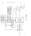
- a mobile communication apparatus including an antenna array is composed of a base station 10 and first, second, ... , and X-th mobile stations 20, 22,..., and 24.
- FIG. 2 is a flowchart for illustrating a mobile communication method according to the present invention, performed in the mobile communication apparatus of FIG. 1.
- This mobile communication method includes a step 30 of obtaining a feedback signal and a step 32 of restoring long-term information from the feedback signal and utilizing the restored long-term information.
- the first, second, ... , and X-th mobile stations 20, 22, ..., and 24 of FIG. 1 perform the same function and each have an antenna array.
- the first, second, ..., and X-th mobile stations 20, 22, ..., and 24 correspond to terminals.
- the base station 10 also has an antenna array.
- each of the first, second, ... , and X-th mobile stations 20, 22, ..., and 24 measures the downlink characteristics H of a channel for each of the antennas of the antenna array included in the base station 10 from a signal received from the base station 10.
- Each mobile station also determines long-term information in which the correlation between channels for respective antennas is reflected, from the measured downlink characteristics H of a channel, transforms the determined long-term information into a feedback signal, and transfers the feedback signal to the base station 10.
- each mobile station interprets the information received from the base station 10, using importance information detected using a basis channel produced from the downlink characteristics H and received signals.
- effective basis information denotes effective basis vectors and effective basis values.
- step 30 An embodiment of step 30 and an embodiment of each of the mobile stations 20, 22, ..., and 24 will now be described with reference to FIGS. 3 and 4.
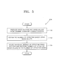
- FIG. 3 is a flowchart for illustrating a preferred embodiment of step 30 of FIG. 2, according to the present invention.
- the downlink characteristics H of a channel are measured in step 40.
- Effective basis vectors and effective basis values which are the long-term information of a channel, are obtained from the measured downlink characteristics H in step 42.
- the determined long-term information is transformed into a feedback signal in step 44.
- Importance information is detected using a produced basis channel and received signals in steps 46 and 48. Transmitted information is interpreted using the importance information, in step 50.
- FIG. 4 is a block diagram of a preferred embodiment of the first, second, ..., or X-th mobile station 20, 22, ..., or 24 of FIG. 1, according to the present invention.
- a mobile station 20, 22, ..., or 24 includes an antenna array 60, a mobile station channel characteristics measurer 62, a mobile station long-term information determiner 64, a mobile station long-term information formatter 80, a basis channel producer 82, a multi-antenna data detector 70, and a information interpreter 72.
- a dark line connecting units indicates a plurality of signals
- a light line connecting units indicates a single signal.
- the mobile station channel characteristics measurer 62 receives signals from the base station 10 through the antenna array 60, measures the downlink characteristics H of a channel for each antenna from the received signals, and outputs the measured downlink characteristics H of the channel to each of the mobile station long-term information determiner 64 and the basis channel producer 82, in step 40.
- H denotes a matrix.
- bold characters denote vectors
- non-bold characters denote scalars.
- the downlink characteristics H of a channel denotes the phase and magnitude of a channel transferred from the base station 10 to a mobile station 20, 22, ..., or 24.
- the channel downlink characteristics H columns are constituted with channels formed by transmission antennas, and rows are constituted with channels formed by reception antennas.
- the transmission antennas denote the antennas of an antenna array included in the base station 10
- the reception antennas denote the antennas of an antenna array included in each of the mobile stations 20, 22, ..., and 24.
- the mobile station long-term information determiner 64 produces basis vectors and basis values from the channel downlink characteristics H spatially measured by the mobile station channel characteristics measurer 62, calculates the number of effective vectors, N B , (hereinafter referred to as an effective basis number) out of the basis vectors using the basis values, and determines effective basis vectors v 1 through v N B , the number of which corresponds to the effective basis number N B , and effective basis values I 1 through I N B , the number of which corresponds to the effective basis number N B , as effective basis information, that is, long-term information, in step 42.
- the effective basis number is equal to or less than the number of antennas included in an antenna array of the base station 10.
- the column components of the matrix H are obtained with respect to the space formed by transmission antennas, and the row components are obtained with respect to the space formed by reception antennas.
- step 42 of FIG. 3 and an embodiment of the mobile station long-term information determiner 64 of FIG. 4 will now be described with reference to FIGS. 5 and 6, respectively.
- FIG. 5 is a flowchart for illustrating step 42A, which is an embodiment of step 42 of FIG. 3, according to the present invention.
- basis vectors v 1 through v antT and basis values I 1 through I antT are produced in step 100.
- antT denotes the number of transmission antennas.
- the effective basis number N B is obtained using the basis values I 1 through I antT in step 102.
- an equal number of effective basis vectors v 1 through v N B to the effective basis number N B and an equal number of effective basis values I 1 through I N B to the effective basis number N B are obtained in step 104.
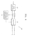
- FIG. 6 is a block diagram of an embodiment 64A of the mobile station long-term information determiner 64 of FIG. 4, according to the present invention.
- the embodiment 64A includes a basis analyzer 120, a selector 122, and an effective basis number calculator 124.
- the basis analyzer 120 produces the basis vectors v 1 through v antT and the basis values I 1 through I antT from the channel downlink characteristics H received from the mobile station channel characteristics measurer 62 using a basis decomposition method, outputs the same to the selector 122, and outputs the basis values I 1 through I antT to the effective basis number calculator 124, in step 100.
- the basis decomposition method means an eigen value decomposition (EVD) technique, a singular value decomposition (SVD) technique, or a technique using an arbitrary orthogonal-normal basis.
- the basis decomposition method is disclosed in a book written by 'G. Golub' and 'C. Van. Loan' with the title of "Matrix Computation" and published in 1996 by the Johns Hopkins University publishing company located in London. If the EVD method is used as the basis decomposition method, the basis values correspond to eigen values.
- the effective basis number calculator 124 counts the number of basis eigen values that exceed a threshold value V th1 and outputs the count value as the effective basis number N B to the selector 122, in step 102.
- the effective basis number counter 124 can be implemented as a counter (not shown).
- the threshold value V th1 is a value close to '0'.
- the selector 122 selects an equal number of effective basis vectors v 1 through v N B to the effective basis number N B from the basis vectors v 1 through v antT received from the basis analyzer 120 and also selects an equal number of effective basis values I 1 through I N B , to the effective basis number N B from the basis values I 1 through I antT received from the basis analyzer 120, in step 104.
- the selector 122 outputs the effective basis vectors v 1 through v N B and the effective basis values I 1 through I N B to each of the mobile station long-term information formatter 80 and the basis channel producer 82.
- the selector 122 may output the effective basis values I 1 through I N B to the information interpreter 72.
- the mobile station long-term information formatter 80 receives the effective basis vectors v 1 through v NB and the effective basis values I 1 through I N B determined by the motile station long-term information determiner 64, transforms the received effective basis information, that is, long-term information, into a feedback signal suitable to be fed back to the base station 10, and transfers the feedback signal to the base station 10 through the antenna array 60, in step 44.
- Being suitable for feedback means quantizing an effective basis vector and an effective basis value to a minimum level just enough not to be lost, and performing time-division multiplexing on the two quantization results.
- the mobile station long-term information formatter 80 formats the effective basis information, that is, long-term information, received from the mobile station long-term information determiner 64, performs time-division multiplexing on the formatted information, and transfers the time-division multiplexing result as a feedback signal to the basis station 10 through the antenna array 60.
- the mobile station long-term information formatter 80 may do code-division multiplexing or frequency-division multiplexing instead of the time-division multiplexing.
- the basis channel producer 82 receives the effective basis vectors v 1 through v N B and effective basis values I 1 through I N B determined by the mobile station long-term information determiner 64 and the channel downlink characteristics H spatially measured by the mobile station channel characteristics measurer 62, produces a basis channel C using Equation 1, and outputs the same to the multi-antenna data detector 70, in step 46.
- the multi-antenna data detector 70 detects at least two importance information by a multi-antenna information detection technique using the received signals received via the antenna array 60 and the basis channel C received from the basis channel producer 82 and outputs the detected importance information to the information interpreter 72, in step 48.
- the number of importance information detected by the multi-antenna data detector 70 varies depending on the embodiment of the information interpreter 72.
- the multi-antenna information detection technique is introduced by G.D. Golden, C.J. Foschini, R.A. Valenzuela, and P.W. Wolniansky on a theory entitled "Detection algorithm and initial laboratory results using V-BLAST space-time communication architecture", IEEE Electronics letters, Vol. 35, No. 1, 7 th January 1999.
- the information interpreter 72 interprets information received from the base station 10 using the importance information received from the multi-antenna data detector 70 and outputs the interpreted information via an output terminal OUT1, in step 50.
- the base station 10 of FIG. 1 receives a feedback signal from the mobile station 20, 22, ... , or 24, restores long-term information, that is, effective basis vectors and effective basis values, from the received feedback signal, sequentially maps a Dedicated Physical CHannel (DPCH) signal, that is, N transmission blocks, to effective basis values, adds the results of basis transformation performed on the mapping results to Pllot CHannel (PICH) signals P 1 (k), P 2 (k), P 3 (k), ..., and P antT (k), and transmits the results of addition to the mobile station 20, 22, ..., or 24, in step 32.
- DPCH Dedicated Physical CHannel
- PICH Pllot CHannel
- PICH Pllot CHannel
- importance information produced by dividing the DPCH signal may be sequentially mapped to the effective basis values.
- step 32 of FIG. 2 includes step 310 of restoring long-term information, steps 312 and 314 of basis-mapping the produced importance information, step 316 of basis-transforming the results of mapping, and step 318 of adding the basis-transformed results to pilot channel signals.
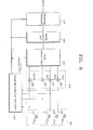
- an embodiment of the base station 10 of FIG. 1 includes an information producer 322, a basis mapping unit 328, a basis transformer 330, an adder 324, an antenna array 326, and a basis information restorer 332.
- a black arrow between members indicates a plurality of signals
- a light arrow indicates a single signal.
- the basis information restorer 332 restores as effective basis information the effective basis vectors v 1 through v N B and effective basis values I 1 through I N B , which correspond to long-term information, from a feedback signal received from the antenna array 326 via an uplink Dedicated Physical Control CHannel (DPCCH), outputs the effective basis values I 1 through I N B to the basis mapping unit 328, and outputs the effective basis vectors v 1 through v N B to the basis transformer 330, in step 310.
- the basis information restorer 332 may output the effective basis values I 1 through I N B to the information producer 322.
- the information producer 322 produces importance information from N received transmission blocks, that is, a DPCH signal, and outputs the produced importance information to the basis mapping unit 328, in step 312.
- N received transmission blocks that is, a DPCH signal
- embodiments of the information producer 322 produce at least two pieces of importance information. That is, the information producer 322 produces as many importance information as the number of effective bases, N B .
- the basis mapping unit 328 sequentially multiplies the importance information received from the information producer 322 by the square roots of the effective basis values I 1 through I N B received from the basis information restorer 332 in a one-to-one correspondence, and outputs the multiplication results as the basis-mapped results to the basis transformer 330, in step 314.
- I 1 is greater than or equal to I 2 .
- Step 312 of FIG. 7 is optional. If step 312 is omitted, step 310 is followed by step 314 where the basis mapping unit 328 sequentially multiplies the DPCH signal by each of the square roots of the effective basis values I 1 through I NB received from the basis information restorer 332 and outputs the multiplication results as the basis-mapped results to the basis transformer 330.
- the base station 10 of FIG. 8 may further include a DPCH producer (not shown) for receiving a DPCCH signal and a Dedicated Physical Information CHannel (DPDCH) signal and multiplexing the received DPCCH and DPDCH signals to have the format of the DPCH signal.
- a DPCH producer (not shown) for receiving a DPCCH signal and a Dedicated Physical Information CHannel (DPDCH) signal and multiplexing the received DPCCH and DPDCH signals to have the format of the DPCH signal.
- DPDCH Dedicated Physical Information CHannel
- the basis transformer 330 multiplies the basis-mapped results received from the basis mapping unit 328 by the effective basis vectors v 1 through v N B received from the basis information restorer 332 in a one-to-one correspondence, sums the multiplied results, and outputs the sum x to the adder 324, in step 316.
- I 1 and I 2 corresponding to the effective basis vectors v 1 and v 2 , respectively, I 1 is equal to or greater than I 2 .
- the adder 324 adds the sum x received from the basis transformer 330 to each of the PICH signals P 1 (k), P 2 (k), P 3 (k), ..., and P antT (k), and outputs the addition results to the antenna array 326, in step 318.
- the PICH signals [P i (k)] (1 ⁇ i ⁇ antT) can be common pilot channel signals CPICH, dedicated CPICH signals DCPICH, or secondary CPICH signals SCPICH. If the PICH signal [P i (k)] is CPICH, P i (k) corresponds to a signal CPICH i .
- the adder 324 may include adding units 360, 362, 364, ..., and 366, the number of which is antT.
- the adding units 360, 362, 364, ... , and 366 add the basis transformation result x received from the basis transformer 330 to the signals P 1 (k), P 2 (k), P 3 (k), ..., and P antT (k), respectively, and output the addition results to the transmission antennas 380, 382, 384, ..., and 386, respectively, in the antenna array 326.
- the antenna array 326 transmits the results of the addition by the adder 324 to the mobile station 20, 22, ..., or 24. To do this, the antenna array 326 includes the antennas 380, 382, 384, ...
- the antennas 380, 382, 384, ..., and 386 transmit the results of the additions by the adding units 360, 362, 364, ..., and 366 to the corresponding mobile station 20, 22, ..., or 24.
- FIG. 9 is a flowchart for illustrating a preferred embodiment 100A of the step 100 of FIG. 5 to obtain the basis vectors v 1 through v antT and the basis values I 1 through I antT .
- the embodiment 100A includes a step 450 of producing channel vectors for respective reception antennas, a step 452 of obtaining autocorrelation matrixes, a step 454 of accumulating the autocorrelation matrixes, and a step 456 of obtaining the basis vectors and basis values using an eigen decomposition technique.
- an embodiment 120A of the basis analyzer 120 of FIG. 6 includes a channel vector producer 410, autocorrelation matrix calculators 412, 414, 416, ..., and 418, accumulators 422, 424, 426, ..., and 428, an adder 430, and an eigen value decomposition unit 432.
- a black arrow between members indicates a plurality of signals
- a light arrow between members indicates a single signal.
- the channel vector producer 410 of FIG. 10 produces channel vectors h 1 , h 2 , h 3 , ..., and h antR of respective reception antennas by dividing the downlink characteristics H of a channel into transceiving antennas, in step 450.
- antR denotes the number of reception antennas, that is, the number of antennas included in the antenna array 60.
- the autocorrelation matrix calculators 412, 414, 416, ..., and 418, the number of which is antR calculate using Equation 4 the autocorrelation matrix R i of each of the channel vectors h 1 , h 2 , h 3 , ..., and h antR produced by the channel vector producer 410 and output the same to the accumulators 422, 424, 426, ..., and 428, the number of which is antR, respectively, in step 452.
- the accumulators 422, 424, 426, ..., and 428 accumulate the autocorrelation matrixes received from the autocorrelation matrix calculators 412, 414, 416, ..., and 418 for a predetermined period of time, respectively, and output the accumulation results to the adder 430, in step 454.
- step 456 the adder 430 sums the results of the accumulations by the accumulators 422, 424, 426, ..., and 428 and outputs the sum to the eigen value decomposition unit 432, and the eigen value decomposition unit 432 obtains eigen vectors and eigen values from the sum obtained by the adder 430 using the above-described eigen decomposition technique, determines the eigen vectors as the basis vectors v 1 through v antT , and determines the eigen values as the basis values I 1 through I antT .
- FIG. 11 is a flowchart for illustrating an embodiment 50A of step 50 of FIG. 3.
- Step 50A includes a step 482 of demodulating two importance information, a step 484 of de-interleaving the demodulated importance information, a step 486 of transforming parallel data into serial data, and a step 488 of correcting the errors of the serial data.
- FIG. 12 is a block diagram of an embodiment 72A of the information interpreter 72 of FIG. 4.
- the information interpreter 72A includes a demodulator 720, a first de-interleaver 722, a first parallel-to-serial (P/S) transformer 724, and a first channel decoder 726.
- P/S parallel-to-serial
- the demodulator 720 demodulates first and second importance information s and p received from the multi-antenna data detector 70 of FIG. 4 and outputs the demodulated importance information to the first de-interleaver 722, in step 482.
- the first de-interleaver 722 de-interleaves the demodulated importance information received from the demodulator 720 and outputs the de-interleaving result to the first P/S transformer 724, in step 484.
- the first P/S transformer 724 transforms the de-interleaving result received from the first de-interleaver 722 into serial data and outputs the serial data to the first channel decoder 726, in step 486.
- the first channel decoder 726 corrects the errors of the serial data received from the first P/S transformer 724 and outputs the corrected serial data via an output terminal OUT2 to, for example, a speaker (not shown), in step 488.
- step 50 When step 50 is implemented as shown in FIG. 11 and the information interpreter 72 is constructed as shown in FIG. 12, step 312 and the information producer 322 can be implemented as shown in FIGS. 13 and 14 according to the present invention, respectively.
- FIG. 13 is a flowchart for illustrating a preferred embodiment 312A of step 312 of FIG. 7.
- Step 312A includes steps 800, 802, and 804 of encoding, interleaving and modulating first and second produced importance information.
- FIG. 14 is a block diagram of a preferred embodiment 322A of the information producer 322 of FIG. 8.
- the information producer 322A includes a first channel encoder 340, a first interleaver 342, and a modulator 344.
- the first channel encoder 340 encodes the DPCH signal to produce the first and second importance information s and p and outputs the first and second importance information s and p to the first interleaver 342, in step 800.
- the first interleaver 342 interleaves the first and second importance information s and p received from the first channel encoder 340, that is, randomly arranges the bits of each of the first and second importance information in a predetermined pattern, and outputs the first and second interleaved importance information to the modulator 344, in step 802.
- the modulator 344 modulates the first and second interleaved importance information and outputs the first and second modulated importance information via output terminals OUT3 and OUT4, respectively, to the basis mapping unit 328 of FIG. 8, in step 804. The method then proceeds to step 314 of FIG. 7.
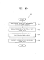
- FIG. 15 is a flowchart for illustrating another embodiment 50B of step 50 of FIG. 3, according to the present invention.
- Step 50B includes steps 850 and 852 of demodulating importance information and transforming demodulation result into serial data, and steps 854 and 856 of de-interleaving the serial data and correcting the errors of the serial data.
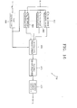
- FIG. 16 is a block diagram of another embodiment 72B of the information interpreter 72 of FIG. 4, according to the present invention.
- the information interpreter 72B includes P 1 -th, P 2 -th, ..., and P NB -th order demodulators 860, 862, ..., and 864, a first controller 866, a second parallel-to-serial (P/S) transformer 868, a second de-interleaver 870, and a second channel decoder 872.
- P/S parallel-to-serial
- a black arrow between members indicates a plurality of signals
- a light arrow between members indicates a single signal.
- the P 1 -th, P 2 -th, ..., and P NB -th order demodulators 860, 862, ..., and 864 demodulate the importance information received from the multi-antenna data detector 70 via an input terminal IN using different orders determined by the first controller 866, that is, a P 1 -th order, a P 2 -th order, ..., and a P N B -th order, in step 850.
- each of the P 1 -th, P 2 -th, ..., and P N B -th order demodulators 860, 862, ..., and 864 can perform quadrature amplitude demodulation or phase shift keying (PSK) demodulation.
- the second P/S transformer 868 transforms the demodulation results into serial data under the control of the first controller 866 and outputs the serial data to the second de-interleaver 870, in step 852.
- the first controller 866 receives the effective basis values I 1 through I NB from the mobile station long-term information determiner 64 of FIG. 4, calculates the ratio of the basis value I 1 to each of the other basis values, determines the orders, that is, the P 1 -th order, the P 2 -th order, ..., and the P N B -th order, from the calculated ratios, and controls the P 1 -th, P 2 -th, ..., and P N B -th order demodulators 860, 862, ..., and 864 and the second P/S transformer 868 according to the determined order values.
- the first controller 866 determines the orders P 1 , P 2 , ..., and P NB using Equation 5: 2 P1-P2 ⁇ I 2 I 1 , 2 P1-P3 ⁇ I 3 I 1
- the second de-interleaver 870 de-interleaves the serial data transformed by the second P/S transformer 868 and outputs the de-interleaved serial data to the second channel decoder 872, in step 854.
- the second channel decoder 872 decodes the de-interleaved serial data received from the second de-interleaver 870 to correct the errors of the de-interleaved serial data and outputs the error-corrected information via an output terminal OUT5 to, for example, a speaker (not shown), in step 856.
- step 50 When step 50 is performed as shown in FIG. 15, and the information interpreter 72 is implemented as shown in FIG. 16, step 312 and the information producer 322 are implemented as shown in FIGS. 17 and 18 according to the preset invention, respectively.
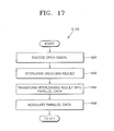
- FIG. 17 is a flowchart for illustrating another embodiment 312B of step 312 of FIG. 7.
- Step 312B includes steps 880, 882 and 884 of encoding and interleaving a signal DPCH and transforming the interleaved information into parallel data, and a step 886 of modulating the parallel data.
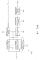
- FIG. 18 is a block diagram of another preferred embodiment 322B of the information producer 322 of FIG. 8.
- the information producer 322B includes a second channel encoder 900, a second interleaver 902, a serial-to-parallel (S/P) transformer 904, a second controller 906, and P 1 -th, P 2 -th, ..., and P N B -th order modulators 908, 910, ..., and 912.
- a black arrow between members indicates a plurality of signals
- a light arrow between members indicates a single signal.
- the second channel encoder 900 receives and encodes the DPCH signal and outputs encoded data to the second interleaver 902, in step 880.
- the second interleaver 902 interleaves the encoded data received from the second channel encoder 900 and outputs the interleaved data to the S/P transformer 904, in step 882.
- the S/P transformer 904 transforms the interleaved data received from the second interleaver 902 into parallel data under the control of the second controller 906 and outputs the parallel data to the P 1 -th, P 2 -th, ..., and P N B -th order modulators 908, 910, ..., and 912, in step 884.
- the P 1 -th, P 2 -th, ..., and P N B -th order modulators 908, 910, ..., and 912 modulate the received parallel data and outputs the modulated parallel data via an output terminal OUT6 to the basis mapping unit 328 of FIG. 8, in step 886.
- the P 1 -th, P 2 -th, ..., and P N B -th order demodulators 860, 862, ..., and 864 of FIG. 16 perform quadrature amplitude demodulations
- the P 1 -th, P 2 -th, ..., and P N B -th order modulators 908, 910, ..., and 912 of FIG. 18 perform quadrature amplitude modulations.
- the P 1 -th, P 2 -th, ..., and P N B -th order demodulators 860, 862, ..., and 864 of FIG. 16 perform PSK demodulations
- the P 1 -th, P 2 -th, ..., and P N B -th order modulators 908, 910, ..., and 912 of FIG. 18 perform PSK modulations.
- the second controller 906 which controls the S/P transformer 904 and the P 1 -th, P 2 -th, ..., and P N B -th order modulators 908, 910, ..., and 912, performs the same function as that of the first controller 866. That is, the second controller 906 determines orders P 1 , P 2 , ..., and P N B from the effective basis values I 1 through I N B received from the basis information restorer 332 of FIG. 8, and controls the S/P transformer 904 and the P 1 -th, P 2 -th, ..., and P N B -th order modulators 908, 910, ..., and 912 according to the determined orders.
- FIGS. 11 through 18 The detailed structure and operation of each of the members shown in FIGS. 11 through 18 are disclosed in a book "Digital Communication", 3 rd edition, chapter 8, written by 'John G. Proakis' and published by McGraw-Hill Book company located in Singapore in 1995.
- a mobile communication apparatus having a base station and mobile stations that each include an antenna array and a mobile communication method performed in the mobile communication apparatus according to the present invention
- information in which the downlink characteristics of a space channel has been reflected is fed back from the mobile stations to the base station. This minimizes the effects of fading, interference, and noise and maximizes throughput.
Abstract
Description
- The present invention relates to the field of mobile communications, and more particularly, to a mobile communication apparatus including an antenna array, the mobile communication apparatus capable of minimizing the effect of fading, interference and noise, and a mobile communication method performed in the mobile communication apparatus.
- A next-generation mobile communication system can transmit information faster than a current PCS mobile communication system. Europe and Japan have adopted a wideband code division multiple access (W-CDMA) system, which is an asynchronous system, as a wireless access standard, while the North America has adopted a CDMA-2000 (multi-carrier code division multiple access) system, which is a synchronous system.
- In a general mobile communication system, several mobile stations communicate with one another through a base station. In order to transmit information at a high speed, a mobile communication system should minimize loss due to the characteristics of a mobile communication channel, such as fading, and user interference. Diversity systems are used to prevent communication from becoming unstable due to fading. A space diversity system, which is a type of diversity system, uses multiple antennas.
- Since the use of multiple antennas can minimize the interference between users, a next-generation mobile communication system must use multiple antennas. Among diversity systems that overcome fading using multiple antennas, a multiple transmitting antenna system used to increase the capacity of a transmission terminal requires a lot of bandwidth in a transmission direction in view of the characteristics of next-generation mobile communication.
- In order to achieve fast information transmission, a general mobile communication system should overcome fading, which is one of the channel characteristics having the most serious effect on communication performance, because fading reduces the amplitude of a received signal from several dB to several tens of dB. Fading can be overcome by several diversity techniques. A general CDMA technique adopts a rake receiver for receiving diverse signals using the delay spread of a channel. A rake receiver performs a diversity reception technique for receiving a multi-path signal. However, the diversity reception technique does not operate when a delay spread is low.
- A time diversity system using interleaving and coding is used in a Doppler spread channel. However, the time diversity system is not suitable for a low-speed Doppler channel. In a room channel with a high delay spread and a pedestrian channel corresponding to a low Doppler channel, a space diversity system is used in order to overcome fading. A space diversity system uses at least two antennas. If a signal received via one antenna is attenuated by fading, the space diversity system receives the signal via another antenna. The space diversity system is classified into a reception antenna diversity system using a reception antenna and a transmission antenna diversity system using a transmission antenna. As it is difficult for a mobile station to install the reception antenna diversity system in respect of area and costs, it is recommended that a base station use the transmission antenna diversity system.
- In the transmission antenna diversity system, there are a closed loop transmission diversity system getting feedback of a downlink channel information from a mobile station to the base station, and an open loop transmission diversity system getting no feedback from a mobile station to the base station. In the transmission antenna diversity system, a mobile station searches for an optimal weighted value by measuring the phase and magnitude of a channel. In order to measure the magnitude and phase of a channel, a base station must send different pilot signals for different antennas. A mobile station measures the magnitude and phase of a channel through the pilot signals and searches for an optimal weighted value from the measured channel magnitude and phase information.
- In the transmission antenna diversity system, if the number of antennas increases, the diversity effect and the signal-to-noise ratio improve. However, the amount of improvement in the diversity effect decreases with an increase in the number of antennas or signal transmission paths used in a base station, that is, with an increase in the degree of diversity. Accordingly, to obtain a significantly improved diversity effect while sacrificing a lot is not preferable. Hence, it is preferable that the number of antennas used in a base station increases to minimize the power of an interference signal and maximize the signal-to-noise ratio of an internal signal, instead of improving the diversity effect.
- A transmission adaptive antenna array system invented in consideration of a beamforming effect that minimizes the influence that interference and noise as well as diversity effect have upon an internal signal is referred to as a downlink beamforming system. A system using feedback information like a transmission diversity system is referred to as a closed loop downlink beamforming system. The closed loop downlink beamforming system, which uses information fed back from a mobile station to a base station, may degrade the performance of communications by failing to properly reflect changes in channel information if a feedback channel does not have a sufficient bandwidth.
- European IMT-2000 standardization group, a 3rd Generation Partnership Project (3GPP) R (Release) 99 version, adopts first and second transmission antenna array (TxAA) modes as a closed loop transmission diversity system for two antennas. Here, the first TxAA mode, which has been proposed by Nokia, feeds only the phase difference between two antennas back. The second TxAA mode, which has been proposed by Motorola, feeds the gains of two antennas as well as their phases back. The first and second TxAA modes are disclosed in the specification set by the 3GPP, a standardization group for a Universal Mobile Telecommunications System (UMTS), which is a European IMT-2000 standard.
- The first or second TxAA mode of a closed loop transmission diversity system uses adaptive array antennas and is designed so as to apply weighted values corresponding to different complex values to the respective adaptive transmission array antennas. The weighted values applied to the adaptive array antennas relate to a transmission channel and can be, for example, w=h* (w and h are vectors). Hereinafter, bold characters indicate vectors, and non-bold characters indicate scalars. Here, h denotes a transmission array channel, and w denotes a transmission array antenna weighted value vector.
- Among mobile communication systems, a system using a frequency division duplex (FDD) generally has a transmission channel and a reception channel that have different characteristics from each other, and accordingly must feed transmission channel information back in order to let a base station know the transmission channel h. To do this, the first or second TxAA mode is designed so that a mobile station obtains the information on the weighted value w to be obtained from the channel information on the channel h and sends the obtained weighted value information to the base station. The first TxAA mode quantizes only a 2-1 part corresponding to a phase component from the information on the weighted value w (= |w1|exp(j1), | w2| exp(j2)], where w1 and w2 denotes scalars) into two bits and feeds the two bits back. Accordingly, the precision of a phase is π/2, and a quantization error is π/4 at the maximum. In order to increase the efficiency of the feedback, the first TxAA mode uses a refining method of updating only one bit out of two feedback bits every moment. For example, a combination of two bits can be {b(2k), b(2k-1)} or {b(2k), b(2k+1)}, where b denotes a bit fed back in units of slots every moment. The second TxAA mode feeds back both a phase and a gain, which are the components of the weighted value information. The phase is fed back 3 bits at a time, and the gain is fed back 1 bit at a time. Accordingly, the precision of the phase is π/4, and a quantization error is π/8 at the maximum. In order to increase the efficiency of the feedback, the second TxAA mode uses a progressive refining mode for updating only one bit out of the four feedback bits every moment. A refining mode provides each bit having an orthogonal basis value, while the progressive refining mode does not set the value of each bit.
- The above-described first and second TxAA modes have the following problems when the number of antennas and the characteristics of a space-time channel vary.
- If the number of antennas increases, a weighted value for each antenna must be fed back, and hence a lot of information to be fed back is created. Thus, depending on the movement speed of a mobile station, the first and second TxAA modes degrade the communication performance. That is, generally, if the movement speed of a mobile station increases in a fading channel, a change in the space-time channel becomes serious. Thus, the feedback speed of channel information must increase. However, if the feedback speed is limited, feedback information increasing with an increase in the number of antennas consequently degrades the performance of communications.
- If the distance between antennas is not sufficient, the correlation between channels in each antenna increases. If the correlation between channels increases, the information amount of a channel matrix decreases. The effective use of a feedback method prevents performance degradation in a high-speed moving body environment even if the number of antennas increases. However, since the first and second TxAA modes are constructed under the assumption that the channels of two antennas that constitute the space-time channels are completely independent from each other, they cannot be used effectively when the number of antennas and the characteristics of the space-time channel change. In addition, the first and second TxAA modes have never been applied to an environment using more than 2 antennas and cannot provide excellent performance even when using 3 or more antennas.
- According to a first aspect of the present invention, there is provided a mobile communication apparatus having a base station and mobile stations that each include an antenna array, in which information having the downlink characteristics of a space channel for every antenna that exists between the mobile stations and the base station is fed back from the mobile stations to the base station, minimizing the effects of fading, interference, and noise and maximizing throughput.
- According to a second aspect of the present invention, there is provided a mobile communication method performed in the mobile communication apparatus having a base station and mobile stations that each include an antenna array.
- In the mobile communication apparatus according to the present invention, each of the mobile stations measures the downlink characteristics of a channel for each antenna from a signal received from a base station, determines long-term information in which the correlation property of the channel for each antenna has been reflected from the measured downlink characteristics, transforms the long-term information into a feedback signal, and transmits the feedback signal to the base station. The base station receives the feedback signal from the mobile station, restores the long-term information from the received feedback signal, performs basis mapping and basis transformation on a dedicated physical channel signal using the restored long-term information, adds the basis-mapped and basis-transformed signal to each of pilot channel signals, and transmits the addition results to the mobile station.
- The mobile communication method performed in the mobile communication apparatus according to the present invention includes two steps. In the first step, the downlink characteristics of a channel for each antenna are measured from a signal received from the base station, long-term information in which the correlation property of the channel for each antenna has been reflected is determined from the measured downlink characteristics, the long-term information is transformed into a feedback signal, the feedback signal is transmitted to the base station. In the second step, the feedback signal is received from the first step, the long-term information is restored from the received feedback signal, basis mapping and basis transformation are performed on a dedicated physical channel signal using the restored long-term information, the basis-mapped and basis-transformed signal is added to each of pilot channel signals, the addition results are transmitted to the mobile station.
- The above objects and advantages of the present invention will become more apparent by describing in detail preferred embodiments thereof with reference to the attached drawings in which:
- FIG. 1 is a schematic block diagram of a mobile communication apparatus including an antenna array, according to the present invention;
- FIG. 2 is a flowchart for illustrating a mobile communication method according to the present invention, performed in the mobile communication apparatus of FIG. 1;
- FIG. 3 is a flowchart for illustrating a preferred embodiment of step 30 of FIG. 2;
- FIG. 4 is a block diagram of a preferred embodiment of the first, second, ..., or X-th mobile station of FIG. 1;
- FIG. 5 is a flowchart for illustrating a preferred embodiment of step 42 of FIG. 3;
- FIG. 6 is a block diagram of an embodiment of the mobile station long-term information determiner of FIG. 4;
- FIG. 7 is a flowchart for illustrating an embodiment of step 32 of FIG. 2, according to the present invention;
- FIG. 8 is a block diagram of an embodiment of the base station of FIG. 1, according to the present invention;
- FIG. 9 is a flowchart for illustrating a preferred embodiment of step 100 of FIG. 5;
- FIG. 10 is a block diagram of an embodiment 120A of the basis analyzer 120 of FIG. 6, according to the present invention;
- FIG. 11 is a flowchart for illustrating an embodiment of step 50 of FIG. 3;
- FIG. 12 is a block diagram of an embodiment of the information interpreter of FIG. 4, the information interpreter performing step 50A of FIG. 11;
- FIG. 13 is a flowchart for illustrating a preferred embodiment of step 312 of FIG. 7;
- FIG. 14 is a block diagram of a preferred embodiment of the information producer of FIG. 8, the information producer performing step 312A of FIG. 13;
- FIG. 15 is a flowchart for illustrating another embodiment of step 50 of FIG. 3;
- FIG. 16 is a block diagram of another embodiment of the information interpreter of FIG. 4, the information interpreter performing step 50B of FIG. 15;
- FIG. 17 is a flowchart for illustrating another embodiment of step 312 of FIG. 7; and
- FIG. 18 is a block diagram of another embodiment of the information producer of FIG. 8.
-
- Referring to FIG. 1, a mobile communication apparatus including an antenna array, according to the present invention, is composed of a base station 10 and first, second, ... , and X-th mobile stations 20, 22,..., and 24.
- FIG. 2 is a flowchart for illustrating a mobile communication method according to the present invention, performed in the mobile communication apparatus of FIG. 1. This mobile communication method includes a step 30 of obtaining a feedback signal and a step 32 of restoring long-term information from the feedback signal and utilizing the restored long-term information.
- The first, second, ... , and X-th mobile stations 20, 22, ..., and 24 of FIG. 1 perform the same function and each have an antenna array. For example, the first, second, ..., and X-th mobile stations 20, 22, ..., and 24 correspond to terminals. The base station 10 also has an antenna array. In step 30 of FIG. 2, each of the first, second, ... , and X-th mobile stations 20, 22, ..., and 24 measures the downlink characteristics H of a channel for each of the antennas of the antenna array included in the base station 10 from a signal received from the base station 10. Each mobile station also determines long-term information in which the correlation between channels for respective antennas is reflected, from the measured downlink characteristics H of a channel, transforms the determined long-term information into a feedback signal, and transfers the feedback signal to the base station 10. In addition, each mobile station interprets the information received from the base station 10, using importance information detected using a basis channel produced from the downlink characteristics H and received signals. Here, effective basis information denotes effective basis vectors and effective basis values.
- An embodiment of step 30 and an embodiment of each of the mobile stations 20, 22, ..., and 24 will now be described with reference to FIGS. 3 and 4.
- FIG. 3 is a flowchart for illustrating a preferred embodiment of step 30 of FIG. 2, according to the present invention. First, the downlink characteristics H of a channel are measured in step 40. Effective basis vectors and effective basis values, which are the long-term information of a channel, are obtained from the measured downlink characteristics H in step 42. The determined long-term information is transformed into a feedback signal in step 44. Importance information is detected using a produced basis channel and received signals in steps 46 and 48. Transmitted information is interpreted using the importance information, in step 50.
- FIG. 4 is a block diagram of a preferred embodiment of the first, second, ..., or X-th mobile station 20, 22, ..., or 24 of FIG. 1, according to the present invention. A mobile station 20, 22, ..., or 24 includes an antenna array 60, a mobile station channel characteristics measurer 62, a mobile station long-term information determiner 64, a mobile station long-term information formatter 80, a basis channel producer 82, a multi-antenna data detector 70, and a information interpreter 72. Here, a dark line connecting units indicates a plurality of signals, and a light line connecting units indicates a single signal.
- Referring to FIGS. 3 and 4, the mobile station channel characteristics measurer 62 receives signals from the base station 10 through the antenna array 60, measures the downlink characteristics H of a channel for each antenna from the received signals, and outputs the measured downlink characteristics H of the channel to each of the mobile station long-term information determiner 64 and the basis channel producer 82, in step 40. Here, H denotes a matrix. Hereinafter, bold characters denote vectors, and non-bold characters denote scalars. The downlink characteristics H of a channel denotes the phase and magnitude of a channel transferred from the base station 10 to a mobile station 20, 22, ..., or 24. In the channel downlink characteristics H, columns are constituted with channels formed by transmission antennas, and rows are constituted with channels formed by reception antennas. Here, the transmission antennas denote the antennas of an antenna array included in the base station 10, and the reception antennas denote the antennas of an antenna array included in each of the mobile stations 20, 22, ..., and 24.
- After step 40, the mobile station long-term information determiner 64 produces basis vectors and basis values from the channel downlink characteristics H spatially measured by the mobile station channel characteristics measurer 62, calculates the number of effective vectors, NB, (hereinafter referred to as an effective basis number) out of the basis vectors using the basis values, and determines effective basis vectors v 1 through v N
B , the number of which corresponds to the effective basis number NB, and effective basis values I1 through INB , the number of which corresponds to the effective basis number NB, as effective basis information, that is, long-term information, in step 42. Here, the effective basis number is equal to or less than the number of antennas included in an antenna array of the base station 10. The column components of the matrix H are obtained with respect to the space formed by transmission antennas, and the row components are obtained with respect to the space formed by reception antennas. - An embodiment of step 42 of FIG. 3 and an embodiment of the mobile station long-term information determiner 64 of FIG. 4 will now be described with reference to FIGS. 5 and 6, respectively.
- FIG. 5 is a flowchart for illustrating step 42A, which is an embodiment of step 42 of FIG. 3, according to the present invention. First, basis vectors v 1 through v antT and basis values I1 through IantT are produced in step 100. Here, antT denotes the number of transmission antennas. Next, the effective basis number NB is obtained using the basis values I1 through IantT in step 102. Thereafter, an equal number of effective basis vectors v 1 through v N
B to the effective basis number NB and an equal number of effective basis values I1 through INB to the effective basis number NB are obtained in step 104. - FIG. 6 is a block diagram of an embodiment 64A of the mobile station long-term information determiner 64 of FIG. 4, according to the present invention. The embodiment 64A includes a basis analyzer 120, a selector 122, and an effective basis number calculator 124.
- Referring to FIGS. 5 and 6, the basis analyzer 120 produces the basis vectors v 1 through v antT and the basis values I1 through IantT from the channel downlink characteristics H received from the mobile station channel characteristics measurer 62 using a basis decomposition method, outputs the same to the selector 122, and outputs the basis values I1 through IantT to the effective basis number calculator 124, in step 100. Here, the basis decomposition method means an eigen value decomposition (EVD) technique, a singular value decomposition (SVD) technique, or a technique using an arbitrary orthogonal-normal basis. The basis decomposition method is disclosed in a book written by 'G. Golub' and 'C. Van. Loan' with the title of "Matrix Computation" and published in 1996 by the Johns Hopkins University publishing company located in London. If the EVD method is used as the basis decomposition method, the basis values correspond to eigen values.
- After step 100, the effective basis number calculator 124 counts the number of basis eigen values that exceed a threshold value Vth1 and outputs the count value as the effective basis number NB to the selector 122, in step 102. To achieve this, the effective basis number counter 124 can be implemented as a counter (not shown). The threshold value Vth1 is a value close to '0'.
- After step 102, the selector 122 selects an equal number of effective basis vectors v 1 through v N
B to the effective basis number NB from the basis vectors v 1 through v antT received from the basis analyzer 120 and also selects an equal number of effective basis values I1 through INB , to the effective basis number NB from the basis values I1 through IantT received from the basis analyzer 120, in step 104. The selector 122 outputs the effective basis vectors v 1 through v NB and the effective basis values I1 through INB to each of the mobile station long-term information formatter 80 and the basis channel producer 82. In an embodiment 72A of the information interpreter 72 as shown in FIG. 12, the selector 122 may output the effective basis values I1 through INB to the information interpreter 72. - Referring back to FIGS. 3 and 4, after step 42, the mobile station long-term information formatter 80 receives the effective basis vectors v 1 through v NB and the effective basis values I1 through IN
B determined by the motile station long-term information determiner 64, transforms the received effective basis information, that is, long-term information, into a feedback signal suitable to be fed back to the base station 10, and transfers the feedback signal to the base station 10 through the antenna array 60, in step 44. Being suitable for feedback means quantizing an effective basis vector and an effective basis value to a minimum level just enough not to be lost, and performing time-division multiplexing on the two quantization results. - To do this, the mobile station long-term information formatter 80 formats the effective basis information, that is, long-term information, received from the mobile station long-term information determiner 64, performs time-division multiplexing on the formatted information, and transfers the time-division multiplexing result as a feedback signal to the basis station 10 through the antenna array 60. The mobile station long-term information formatter 80 may do code-division multiplexing or frequency-division multiplexing instead of the time-division multiplexing.
- After step 44, the basis channel producer 82 receives the effective basis vectors v 1 through v N
B and effective basis values I1 through INB determined by the mobile station long-term information determiner 64 and the channel downlink characteristics H spatially measured by the mobile station channel characteristics measurer 62, produces a basis channel C using Equation 1, and outputs the same to the multi-antenna data detector 70, in step 46. Equation 1 is: - After step 46, the multi-antenna data detector 70 detects at least two importance information by a multi-antenna information detection technique using the received signals received via the antenna array 60 and the basis channel C received from the basis channel producer 82 and outputs the detected importance information to the information interpreter 72, in step 48. The number of importance information detected by the multi-antenna data detector 70 varies depending on the embodiment of the information interpreter 72. The multi-antenna information detection technique is introduced by G.D. Golden, C.J. Foschini, R.A. Valenzuela, and P.W. Wolniansky on a theory entitled "Detection algorithm and initial laboratory results using V-BLAST space-time communication architecture", IEEE Electronics letters, Vol. 35, No. 1, 7th January 1999.
- After step 48, the information interpreter 72 interprets information received from the base station 10 using the importance information received from the multi-antenna data detector 70 and outputs the interpreted information via an output terminal OUT1, in step 50.
- Referring back to FIG. 2, after step 30, the base station 10 of FIG. 1 receives a feedback signal from the mobile station 20, 22, ... , or 24, restores long-term information, that is, effective basis vectors and effective basis values, from the received feedback signal, sequentially maps a Dedicated Physical CHannel (DPCH) signal, that is, N transmission blocks, to effective basis values, adds the results of basis transformation performed on the mapping results to Pllot CHannel (PICH) signals P1(k), P2(k), P3(k), ..., and PantT(k), and transmits the results of addition to the mobile station 20, 22, ..., or 24, in step 32. In the present invention, instead of the DPCH signal, importance information produced by dividing the DPCH signal may be sequentially mapped to the effective basis values.
- An embodiment of step 32 of FIG. 2 and an embodiment of the base station 10 of FIG. 1, according to the present invention, will now be described with reference to FIGS. 7 and 8, respectively. Referring to FIG. 7, an embodiment of step 32 of FIG. 2 includes step 310 of restoring long-term information, steps 312 and 314 of basis-mapping the produced importance information, step 316 of basis-transforming the results of mapping, and step 318 of adding the basis-transformed results to pilot channel signals.
- Referring to FIG. 8, an embodiment of the base station 10 of FIG. 1 includes an information producer 322, a basis mapping unit 328, a basis transformer 330, an adder 324, an antenna array 326, and a basis information restorer 332. Here, a black arrow between members indicates a plurality of signals, and a light arrow indicates a single signal.
- In order to perform step 32 of FIG. 2, first, the basis information restorer 332 restores as effective basis information the effective basis vectors v 1 through v N
B and effective basis values I1 through INB , which correspond to long-term information, from a feedback signal received from the antenna array 326 via an uplink Dedicated Physical Control CHannel (DPCCH), outputs the effective basis values I1 through INB to the basis mapping unit 328, and outputs the effective basis vectors v 1 through v NB to the basis transformer 330, in step 310. Depending on the embodiment of the information producer 322 to be described later, the basis information restorer 332 may output the effective basis values I1 through INB to the information producer 322. - After step 310, the information producer 322 produces importance information from N received transmission blocks, that is, a DPCH signal, and outputs the produced importance information to the basis mapping unit 328, in step 312. As will be described later, embodiments of the information producer 322 produce at least two pieces of importance information. That is, the information producer 322 produces as many importance information as the number of effective bases, NB.
- After step 312, the basis mapping unit 328 sequentially multiplies the importance information received from the information producer 322 by the square roots of the effective basis values I1 through IN
B received from the basis information restorer 332 in a one-to-one correspondence, and outputs the multiplication results as the basis-mapped results to the basis transformer 330, in step 314. If the information producer 322 produces first and second importance information Smod and pmod, and NB is 2, basis-mapped results smap and pmap can be calculated using Equation 2: - Step 312 of FIG. 7 is optional. If step 312 is omitted, step 310 is followed by step 314 where the basis mapping unit 328 sequentially multiplies the DPCH signal by each of the square roots of the effective basis values I1 through INB received from the basis information restorer 332 and outputs the multiplication results as the basis-mapped results to the basis transformer 330.
- The base station 10 of FIG. 8 may further include a DPCH producer (not shown) for receiving a DPCCH signal and a Dedicated Physical Information CHannel (DPDCH) signal and multiplexing the received DPCCH and DPDCH signals to have the format of the DPCH signal.
- After step 314, the basis transformer 330 multiplies the basis-mapped results received from the basis mapping unit 328 by the effective basis vectors v 1 through v N
B received from the basis information restorer 332 in a one-to-one correspondence, sums the multiplied results, and outputs the sum x to the adder 324, in step 316. If the basis-mapped results are as shown in Equation 2, the basis transformer 328 can obtain a sum x as expressed in Equation 3: - After step 316, the adder 324 adds the sum x received from the basis transformer 330 to each of the PICH signals P1(k), P2(k), P3(k), ..., and PantT(k), and outputs the addition results to the antenna array 326, in step 318. The PICH signals [Pi(k)] (1 ≤ i ≤ antT) can be common pilot channel signals CPICH, dedicated CPICH signals DCPICH, or secondary CPICH signals SCPICH. If the PICH signal [Pi(k)] is CPICH, Pi(k) corresponds to a signal CPICHi. In order to perform step 318, the adder 324 may include adding units 360, 362, 364, ..., and 366, the number of which is antT. The adding units 360, 362, 364, ... , and 366 add the basis transformation result x received from the basis transformer 330 to the signals P1(k), P2(k), P3(k), ..., and PantT(k), respectively, and output the addition results to the transmission antennas 380, 382, 384, ..., and 386, respectively, in the antenna array 326. The antenna array 326 transmits the results of the addition by the adder 324 to the mobile station 20, 22, ..., or 24. To do this, the antenna array 326 includes the antennas 380, 382, 384, ... , and 386, the number of which is antT. The antennas 380, 382, 384, ..., and 386 transmit the results of the additions by the adding units 360, 362, 364, ..., and 366 to the corresponding mobile station 20, 22, ..., or 24.
- An embodiment of the step 100 of FIG. 5 and an embodiment of the basis analyzer 120 of FIG. 6, according to the present invention, will now be described with reference to FIGS. 9 and 10. FIG. 9 is a flowchart for illustrating a preferred embodiment 100A of the step 100 of FIG. 5 to obtain the basis vectors v 1 through v antT and the basis values I1 through IantT. The embodiment 100A includes a step 450 of producing channel vectors for respective reception antennas, a step 452 of obtaining autocorrelation matrixes, a step 454 of accumulating the autocorrelation matrixes, and a step 456 of obtaining the basis vectors and basis values using an eigen decomposition technique.
- Referring to FIG. 10, an embodiment 120A of the basis analyzer 120 of FIG. 6 includes a channel vector producer 410, autocorrelation matrix calculators 412, 414, 416, ..., and 418, accumulators 422, 424, 426, ..., and 428, an adder 430, and an eigen value decomposition unit 432. Here, a black arrow between members indicates a plurality of signals, and a light arrow between members indicates a single signal.
- The channel vector producer 410 of FIG. 10 produces channel vectors h 1, h 2, h 3, ..., and h antR of respective reception antennas by dividing the downlink characteristics H of a channel into transceiving antennas, in step 450. Here, antR denotes the number of reception antennas, that is, the number of antennas included in the antenna array 60. After step 450, the autocorrelation matrix calculators 412, 414, 416, ..., and 418, the number of which is antR, calculate using Equation 4 the autocorrelation matrix Ri of each of the channel vectors h 1, h 2, h 3, ..., and h antR produced by the channel vector producer 410 and output the same to the accumulators 422, 424, 426, ..., and 428, the number of which is antR, respectively, in step 452. Equation 4 is as follows:
- After step 452, the accumulators 422, 424, 426, ..., and 428 accumulate the autocorrelation matrixes received from the autocorrelation matrix calculators 412, 414, 416, ..., and 418 for a predetermined period of time, respectively, and output the accumulation results to the adder 430, in step 454. After step 454, in step 456, the adder 430 sums the results of the accumulations by the accumulators 422, 424, 426, ..., and 428 and outputs the sum to the eigen value decomposition unit 432, and the eigen value decomposition unit 432 obtains eigen vectors and eigen values from the sum obtained by the adder 430 using the above-described eigen decomposition technique, determines the eigen vectors as the basis vectors v 1 through v antT, and determines the eigen values as the basis values I1 through IantT.
- Preferred embodiments of the step 50 of FIG. 3, preferred embodiments of the information interpreter 72 for performing the step 50, preferred embodiments of the step 312 of FIG. 7, and preferred embodiments of the information producer 322 for performing the step 312 will now be described referring to the attached drawings.
- FIG. 11 is a flowchart for illustrating an embodiment 50A of step 50 of FIG. 3. Step 50A includes a step 482 of demodulating two importance information, a step 484 of de-interleaving the demodulated importance information, a step 486 of transforming parallel data into serial data, and a step 488 of correcting the errors of the serial data.
- FIG. 12 is a block diagram of an embodiment 72A of the information interpreter 72 of FIG. 4. In order to perform step 50A of FIG. 11, the information interpreter 72A includes a demodulator 720, a first de-interleaver 722, a first parallel-to-serial (P/S) transformer 724, and a first channel decoder 726.
- Referring to FIGS. 11 and 12, after step 48 of FIG. 3, the demodulator 720 demodulates first and second importance information s and p received from the multi-antenna data detector 70 of FIG. 4 and outputs the demodulated importance information to the first de-interleaver 722, in step 482. After step 482, the first de-interleaver 722 de-interleaves the demodulated importance information received from the demodulator 720 and outputs the de-interleaving result to the first P/S transformer 724, in step 484. After step 484, the first P/S transformer 724 transforms the de-interleaving result received from the first de-interleaver 722 into serial data and outputs the serial data to the first channel decoder 726, in step 486. After the step 486, the first channel decoder 726 corrects the errors of the serial data received from the first P/S transformer 724 and outputs the corrected serial data via an output terminal OUT2 to, for example, a speaker (not shown), in step 488.
- When step 50 is implemented as shown in FIG. 11 and the information interpreter 72 is constructed as shown in FIG. 12, step 312 and the information producer 322 can be implemented as shown in FIGS. 13 and 14 according to the present invention, respectively.
- FIG. 13 is a flowchart for illustrating a preferred embodiment 312A of step 312 of FIG. 7. Step 312A includes steps 800, 802, and 804 of encoding, interleaving and modulating first and second produced importance information.
- FIG. 14 is a block diagram of a preferred embodiment 322A of the information producer 322 of FIG. 8. In order to perform step 312A of FIG. 13, the information producer 322A includes a first channel encoder 340, a first interleaver 342, and a modulator 344.
- Referring to FIGS. 13 and 14, after step 310 of FIG. 7, the first channel encoder 340 encodes the DPCH signal to produce the first and second importance information s and p and outputs the first and second importance information s and p to the first interleaver 342, in step 800. After step 800, the first interleaver 342 interleaves the first and second importance information s and p received from the first channel encoder 340, that is, randomly arranges the bits of each of the first and second importance information in a predetermined pattern, and outputs the first and second interleaved importance information to the modulator 344, in step 802. After step 802, the modulator 344 modulates the first and second interleaved importance information and outputs the first and second modulated importance information via output terminals OUT3 and OUT4, respectively, to the basis mapping unit 328 of FIG. 8, in step 804. The method then proceeds to step 314 of FIG. 7.
- FIG. 15 is a flowchart for illustrating another embodiment 50B of step 50 of FIG. 3, according to the present invention. Step 50B includes steps 850 and 852 of demodulating importance information and transforming demodulation result into serial data, and steps 854 and 856 of de-interleaving the serial data and correcting the errors of the serial data.
- FIG. 16 is a block diagram of another embodiment 72B of the information interpreter 72 of FIG. 4, according to the present invention. In order to achieve step 50B of FIG. 15, the information interpreter 72B includes P1-th, P2-th, ..., and PNB -th order demodulators 860, 862, ..., and 864, a first controller 866, a second parallel-to-serial (P/S) transformer 868, a second de-interleaver 870, and a second channel decoder 872. Here, a black arrow between members indicates a plurality of signals, and a light arrow between members indicates a single signal.
- Referring to FIGS. 15 and 16, after step 48 of FIG. 3, the P1-th, P2-th, ..., and PNB -th order demodulators 860, 862, ..., and 864 demodulate the importance information received from the multi-antenna data detector 70 via an input terminal IN using different orders determined by the first controller 866, that is, a P1-th order, a P2-th order, ..., and a PN
B -th order, in step 850. To do this, each of the P1-th, P2-th, ..., and PNB -th order demodulators 860, 862, ..., and 864 can perform quadrature amplitude demodulation or phase shift keying (PSK) demodulation. After step 850, the second P/S transformer 868 transforms the demodulation results into serial data under the control of the first controller 866 and outputs the serial data to the second de-interleaver 870, in step 852. - The first controller 866 receives the effective basis values I1 through INB from the mobile station long-term information determiner 64 of FIG. 4, calculates the ratio of the basis value I1 to each of the other basis values, determines the orders, that is, the P1-th order, the P2-th order, ..., and the PN
B -th order, from the calculated ratios, and controls the P1-th, P2-th, ..., and PNB -th order demodulators 860, 862, ..., and 864 and the second P/S transformer 868 according to the determined order values. For example, the first controller 866 determines the orders P1, P2, ..., and PNB using Equation 5: - After step 852, the second de-interleaver 870 de-interleaves the serial data transformed by the second P/S transformer 868 and outputs the de-interleaved serial data to the second channel decoder 872, in step 854. After step 854, the second channel decoder 872 decodes the de-interleaved serial data received from the second de-interleaver 870 to correct the errors of the de-interleaved serial data and outputs the error-corrected information via an output terminal OUT5 to, for example, a speaker (not shown), in step 856.
- When step 50 is performed as shown in FIG. 15, and the information interpreter 72 is implemented as shown in FIG. 16, step 312 and the information producer 322 are implemented as shown in FIGS. 17 and 18 according to the preset invention, respectively.
- FIG. 17 is a flowchart for illustrating another embodiment 312B of step 312 of FIG. 7. Step 312B includes steps 880, 882 and 884 of encoding and interleaving a signal DPCH and transforming the interleaved information into parallel data, and a step 886 of modulating the parallel data.
- FIG. 18 is a block diagram of another preferred embodiment 322B of the information producer 322 of FIG. 8. In order to perform step 312B of FIG. 17, the information producer 322B includes a second channel encoder 900, a second interleaver 902, a serial-to-parallel (S/P) transformer 904, a second controller 906, and P1-th, P2-th, ..., and PN
B -th order modulators 908, 910, ..., and 912. Here, a black arrow between members indicates a plurality of signals, and a light arrow between members indicates a single signal. - Referring to FIGS. 17 and 18, after step 310 of FIG. 7, the second channel encoder 900 receives and encodes the DPCH signal and outputs encoded data to the second interleaver 902, in step 880. After step 880, the second interleaver 902 interleaves the encoded data received from the second channel encoder 900 and outputs the interleaved data to the S/P transformer 904, in step 882. After step 882, the S/P transformer 904 transforms the interleaved data received from the second interleaver 902 into parallel data under the control of the second controller 906 and outputs the parallel data to the P1-th, P2-th, ..., and PN
B -th order modulators 908, 910, ..., and 912, in step 884. After step 884, the P1-th, P2-th, ..., and PNB -th order modulators 908, 910, ..., and 912 modulate the received parallel data and outputs the modulated parallel data via an output terminal OUT6 to the basis mapping unit 328 of FIG. 8, in step 886. If the P1-th, P2-th, ..., and PNB -th order demodulators 860, 862, ..., and 864 of FIG. 16 perform quadrature amplitude demodulations, the P1-th, P2-th, ..., and PNB -th order modulators 908, 910, ..., and 912 of FIG. 18 perform quadrature amplitude modulations. Similarly, If the P1-th, P2-th, ..., and PNB -th order demodulators 860, 862, ..., and 864 of FIG. 16 perform PSK demodulations, the P1-th, P2-th, ..., and PNB -th order modulators 908, 910, ..., and 912 of FIG. 18 perform PSK modulations. - Here, the second controller 906, which controls the S/P transformer 904 and the P1-th, P2-th, ..., and PN
B -th order modulators 908, 910, ..., and 912, performs the same function as that of the first controller 866. That is, the second controller 906 determines orders P1, P2, ..., and PNB from the effective basis values I1 through INB received from the basis information restorer 332 of FIG. 8, and controls the S/P transformer 904 and the P1-th, P2-th, ..., and PNB -th order modulators 908, 910, ..., and 912 according to the determined orders. - The detailed structure and operation of each of the members shown in FIGS. 11 through 18 are disclosed in a book "Digital Communication", 3rd edition, chapter 8, written by 'John G. Proakis' and published by McGraw-Hill Book company located in Singapore in 1995.
- As described above, in a mobile communication apparatus having a base station and mobile stations that each include an antenna array and a mobile communication method performed in the mobile communication apparatus according to the present invention, information in which the downlink characteristics of a space channel has been reflected is fed back from the mobile stations to the base station. This minimizes the effects of fading, interference, and noise and maximizes throughput.
Claims (26)
- A mobile communication apparatus having an antenna array, the apparatus comprising:wherein the mobile station and the base station each have the antenna array.a mobile station for measuring downlink characteristics of a channel for each antenna from a signal received from a base station, determining long-term information in which correlation property of the channel for each antenna has been reflected from the measured downlink characteristics, transforming the long-term information into a feedback signal, and transmitting the feedback signal to the base station; andthe base station for receiving the feedback signal, restoring the long-term information from the received feedback signal, performing basis mapping and basis transformation on a dedicated physical channel signal using the restored long-term information, adding the basis-mapped and basis-transformed signal to each of pilot channel signals, and transmitting the addition results to the mobile station,
- The mobile communication apparatus of claim 1, wherein the mobile station comprises:a mobile station channel characteristics measurer for receiving a signal from the base station, spatially measuring the downlink characteristics from the received signal, and outputting the measured downlink characteristics;a mobile station long-term information determiner for producing basis vectors and basis values from the measured downlink characteristics received from the mobile station channel characteristics measurer, calculating an effective basis number, which indicates the number of effective basis vectors among the basis vectors, from the basis values, and outputting effective basis vectors and effective basis values as the long-term information; anda mobile station long-term information formatter for transforming the long-term information received from the mobile station long-term information determiner into the feedback signal.
- The mobile communication apparatus of claim 2, wherein the base station comprises:wherein the addition results are transferred via the antenna array in the base station to the mobile station.a basis information restorer for receiving the feedback signal, restoring the long-term information from the feedback signal, and outputting the restored long-term information;a basis mapping unit for performing the basis mapping by mapping the dedicated physical channel signal to the effective basis values out of the long-term information received from the basis information restorer and outputting the mapping results;a basis transformer for performing the basis transformation by multiplying the mapping results received from the basis mapping unit by the effective basis vectors out of the long-term information and outputting the basis transformation results; andan adder for adding the transformation results received from the basis transformer to the pilot channel signals and outputting the addition results,
- The mobile communication apparatus of claim 3, wherein the mobile station long-term information determiner comprises:a basis analyzer for producing the basis vectors and the basis values from the measured downlink characteristics using a basis analysis technique;an effective basis number calculator for counting the number of basis values that exceeds a threshold value and outputting the counted value as the effective basis number; anda selector for selecting the effective basis vectors whose number corresponds to the effective basis number from the basis vectors received from the basis analyzer and selecting the effective basis values whose number corresponds to the effective basis number from the basis values received from the basis analyzer.
- The mobile communication apparatus of claim 4, wherein the basis analyzer comprises:a channel vector producer for dividing the downlink characteristics into channel vectors associated with the antennas of the antenna array included in the mobile station and outputting the channel vectors;autocorrelation matrix calculators for calculating the autocorrelation matrixes for the respective channel vectors received from the channel vector producer and outputting the calculated autocorrelation matrixes;accumulators for accumulating for a predetermined period of time each of the autocorrelation matrixes received from the autocorrelation matrix calculators;an adder for summing the accumulation results received from the accumulators; andan eigen value decomposition unit for producing the basis vectors and the basis values from the sum received from the adder using the basis analysis technique.
- The mobile communication apparatus of claim 4 or 5, wherein the mobile station produces a basis channel by calculating the long-term information and the downlink characteristics, detects at least two importance information from the basis channel and received signals received via the antenna array using a multi-antenna information detection technique, and interprets information received from the base station from the importance information, and the base station produces the at least two importance information by dividing the dedicated physical channel signal and performing the basis mapping and basis transformation on the importance information using the long-term information.
- The mobile communication apparatus of claim 4, 5 or 6, wherein the mobile station further comprises:wherein v 1 through v Na basis channel producing unit for producing the basis channel C using the long-term information and the downlink characteristics H as follows:
B denote the effective basis vectors, I1 through INB denote the effective basis values, and NB denotes the effective basis number;
a multi-antenna data detector for detecting the importance information from the received signals received via the antenna array and the basis channel C received from the basis channel producer using the multi-antenna information detection technique; and
an information interpreter for interpreting information received from the base station using the importance information received from the multi-antenna data detector. - The mobile communication apparatus of claim 7, wherein the base station further comprises a information producer for producing the importance information by dividing the dedicated physical channel signal, and outputting the produced importance information to the basis mapping unit, and the basis mapping unit performs the basis mapping by mapping the importance information to the effective basis values.
- The mobile communication apparatus of claim 8, wherein the information interpreter comprises:a demodulator for demodulating the importance information received from the multi-antenna data detector;a first de-interleaver for de-interleaving the demodulated information received from the demodulator;a first parallel-to-serial (P/S) transformer for transforming the de-interleaving result received from the first de-interleaver into serial data; anda first channel decoder for correcting the errors of the serial data received from the first P/S transformer.
- The mobile communication apparatus of claim 8, wherein the information interpreter comprises:P1-th, P2-th, ..., and PN
B -th order demodulators for demodulating the importance information received from the multi-antenna data detector using an equal number of different orders to the effective basis number;a second P/S transformer for transforming the demodulation results received from the P1-th, P2-th, ..., and PNB -th order demodulators into serial dataa first controller for calculating the ratios between the effective basis values received from the mobile station long-term information determiner, determining the different orders, that is, a P1-th order, a P2-th order, ..., and a PNB -th order, from the calculated ratios, and controlling the P1-th, P2-th, ..., and PNB -th order demodulators and the second P/S transformer by the determined orders;a second de-interleaver for de-interleaving the serial data received from the second P/S transformer;a second channel decoder for decoding the de-interleaved serial data received from the second de-interleaver to correct the errors of the de-interleaved serial data. - The mobile communication apparatus of claim 9, wherein the information producer comprises:a first channel encoder for encoding the dedicated physical channel signal;a first interleaver for interleaving the encoding result received from the first channel encoder; anda modulator for modulating the interleaving result received from the first interleaver and outputting the modulation result as the importance information to the basis mapping unit.
- The mobile communication apparatus of claim 10, wherein the information producer comprises:a second channel encoder for encoding the dedicated physical channel signal;a second interleaver for interleaving the encoding result received from the second channel encoder;a serial-to-parallel (S/P) transformer for transforming the interleaving result received from the second interleaver into parallel data;P1-th, P2-th, ..., and PN
B -th order modulators for modulating the parallel data received from the S/P transformer using as many different orders as the effective basis number and outputting the modulation results as the importance information to the basis mapping unit; anda second controller for determining the orders from the effective basis values received from the basis information restorer and controlling the S/P transformer and the P1-th, P2-th, ..., and PNB -th order modulators by the determined orders. - The mobile communication apparatus of claim 10, wherein the P1-th, P2-th, ..., and PN
B -th order demodulators perform quadrature amplitude demodulations, and the P1-th, P2-th, ..., and PNB -th order modulators perform quadrature amplitude modulations. - The mobile communication apparatus of claim 10, wherein the P1-th, P2-th, ..., and PN
B -th order demodulators perform phase shift keying (PSK) demodulations, and the P1-th, P2-th, ..., and PNB -th order modulators perform PSK modulations. - A mobile communication method performed in a mobile communication apparatus having a base station and a mobile station, each including an antenna array, the method comprising:(a) measuring downlink characteristics of a channel for each antenna from a signal received from the base station, determining long-term information in which the correlation property of the channel for each antenna has been reflected from the measured downlink characteristics, transforming the long-term information into a feedback signal, and transmitting the feedback signal to the base station; and(b) receiving the feedback signal, restoring the long-term information from the received feedback signal, performing basis mapping and basis transformation on a dedicated physical channel signal using the restored long-term information, adding the basis-mapped and basis-transformed signal to each of pilot channel signals, and transmitting the addition results to the mobile station.
- The mobile communication method of claim 15, wherein the step (a) comprises:(a1) receiving the signal from the base station and spatially measuring the downlink characteristics from the received signal;(a2) producing basis vectors and basis values from the measured downlink characteristics, calculating an effective basis number indicating the number of effective basis vectors among the basis vectors from the basis values, and determining effective basis vectors and effective basis values as the long-term information; and(a3) transforming the long-term information into the feedback signal.
- The mobile communication method of claim 16, wherein the step (b) comprises:wherein the addition results are transmitted via the antenna array in the base station to the mobile station.(b1) receiving the feedback signal and restoring the long-term information from the feedback signal;(b2) performing the basis mapping by mapping the dedicated physical channel signal to the effective basis values out of the restored long-term information;(b3) performing the basis transformation by multiplying the basis-mapping results by the effective basis vectors out of the long-term information; and(b4) adding the basis-transformation results to the pilot channel signals,
- The mobile communication method of claim 17, wherein the step (a2) comprises:(a21) producing the basis vectors and the basis values from the measured downlink characteristics using a basis analysis technique;(a22) determining the number of basis values that exceed a threshold value, as the effective basis number; and(a23) selecting the effective basis vectors whose number corresponds to the effective basis number from the produced basis vectors and selecting the effective basis values whose number corresponds to the effective basis number from the produced basis values.
- The mobile communication method of claim 18, wherein the step (a21) comprises:dividing the downlink characteristics to obtain channel vectors associated with the antennas of the antenna array included in the mobile station;obtaining autocorrelation matrixes for the respective channel vectors;accumulating each of the autocorrelation matrixes for a predetermined period of time; andsumming the accumulation results and producing the basis vectors and the basis values from the sum the basis analysis technique.
- The mobile communication method of claim 18 or 19, wherein, in step (a), a basis channel is produced by calculating the long-term information and the downlink characteristics, at least two pieces of importance information are detected from the basis channel and received signals received via the antenna array using a multi-antenna information detection technique, and information received from the base station is interpreted from the importance information, and, in the step (b), at least two pieces of importance information are produced by dividing the dedicated physical channel signal and performing the basis mapping and basis transformation on the importance information using the long-term information.
- The mobile communication method of claim 20, wherein, after the step (a3), the step (a) further comprises:(a4) producing the basis channel C by calculating the long-term information and the downlink characteristics H as follows:(a5) detecting the importance information from the received signals and the basis channel C using the multi-antenna information detection technique; and(a6) interpreting information received from the base station using the detected importance information.
- The mobile communication method of claim 21, wherein the step (b) further comprises dividing the dedicated physical channel signal to produce the importance information, after the step (b1), and proceeding the step (b2), in which the importance information produced in step (b5) are mapped to the effective basis values.
- The mobile communication method of claim 22, wherein the step (a6) comprises:demodulating the importance information detected in the step (a5);de-interleaving the demodulation results;transforming the de-interleaving results into serial data; andcorrecting the errors of the serial data.
- The mobile communication method of claim 22, wherein the step (a6) comprises:wherein the different orders are determined from ratio between the effective basis values determined in the step (a2).demodulating the importance information detected in the step (a5) using different orders;transforming the demodulation results into serial data;de-interleaving the serial data; anddecoding the de-interleaved serial data to correct errors of the de-interleaved serial data,
- The mobile communication method of claim 23, wherein the step (b5) comprises:encoding the dedicated physical channel signal, after the step (b1);interleaving the encoding result; andmodulating the interleaving result to obtain the importance information and proceeding to the step (b2).
- The mobile communication method of claim 24, wherein the step (b5) comprises:wherein the orders are determined from the ratios between the effective basis values out of the long-term information restored in the step (b1).encoding the dedicated physical channel signal, after the step (b1);interleaving the encoding result;transforming the interleaving result into parallel data; andmodulating the parallel data using different orders to obtain the importance information and proceeding to the step (b2),
Applications Claiming Priority (2)
| Application Number | Priority Date | Filing Date | Title |
|---|---|---|---|
| KR20010051590A KR100615888B1 (en) | 2001-08-25 | 2001-08-25 | Mobile communication apparatus and method including antenna array |
| KR2001051590 | 2001-08-25 |
Publications (2)
| Publication Number | Publication Date |
|---|---|
| EP1289169A1 true EP1289169A1 (en) | 2003-03-05 |
| EP1289169B1 EP1289169B1 (en) | 2005-10-26 |
Family
ID=36650912
Family Applications (1)
| Application Number | Title | Priority Date | Filing Date |
|---|---|---|---|
| EP20020255828 Expired - Fee Related EP1289169B1 (en) | 2001-08-25 | 2002-08-21 | Mobile communication apparatus including antenna array and mobile communication method |
Country Status (6)
| Country | Link |
|---|---|
| US (1) | US7206353B2 (en) |
| EP (1) | EP1289169B1 (en) |
| JP (1) | JP4002487B2 (en) |
| KR (1) | KR100615888B1 (en) |
| CN (1) | CN1271868C (en) |
| DE (1) | DE60206860T2 (en) |
Cited By (3)
| Publication number | Priority date | Publication date | Assignee | Title |
|---|---|---|---|---|
| EP1349297A1 (en) * | 2002-03-29 | 2003-10-01 | Lucent Technologies Inc. | A closed loop multiple antenna system |
| EP1349304A2 (en) * | 2002-03-29 | 2003-10-01 | Lucent Technologies Inc. | Method for generating channel quality feedback information in a two transmit N-receive antenna system |
| GB2516617A (en) * | 2013-06-12 | 2015-02-04 | Socowave Technologies Ltd | Network element, integrated circuit and method of assigning channels |
Families Citing this family (11)
| Publication number | Priority date | Publication date | Assignee | Title |
|---|---|---|---|---|
| KR100596413B1 (en) * | 2001-10-24 | 2006-07-03 | 삼성전자주식회사 | Mobile communication apparatus and method having transmitting/receiving multiantenna |
| KR100917882B1 (en) | 2002-07-10 | 2009-09-16 | 삼성전자주식회사 | Mobile communication apparatus and method having base-station/mobile-station multiantenna |
| US7558314B2 (en) * | 2002-09-23 | 2009-07-07 | Telefonaktiebolaget L M Ericsson (Publ) | Method and device for detection of a UMTS signal |
| KR100900970B1 (en) | 2002-10-19 | 2009-06-08 | 삼성전자주식회사 | Mobile communication apparatus and method having base-station and mobile-station multiantenna |
| KR100575993B1 (en) * | 2003-08-07 | 2006-05-02 | 삼성전자주식회사 | Method and apparatus for scheduling multi-user in wireless communication system using multiple transmit/receive antenna |
| KR100915161B1 (en) * | 2004-09-17 | 2009-09-03 | 가부시키가이샤 엔.티.티.도코모 | Mobile communication method, mobile station and base station |
| KR100831324B1 (en) * | 2004-10-15 | 2008-05-22 | 삼성전자주식회사 | Apparatus for measuring radiation pattern of array antennas in Smart Antenna System |
| CN101116264B (en) * | 2005-02-07 | 2013-03-06 | 艾利森电话股份有限公司 | Transmission rate measurement |
| US8064532B2 (en) | 2005-09-30 | 2011-11-22 | Alexander Alexandrovich Maltsev | Method and scheme for space-time coded cochannel interference cancellation |
| US9065512B2 (en) | 2009-06-23 | 2015-06-23 | Koninklijke Philips N.V. | Antenna configuration for co-operative beamforming |
| CN102833768A (en) * | 2012-08-01 | 2012-12-19 | 华为终端有限公司 | Antenna spatial correlation measuring method and device and terminal device |
Citations (5)
| Publication number | Priority date | Publication date | Assignee | Title |
|---|---|---|---|---|
| WO1998009381A1 (en) * | 1996-08-29 | 1998-03-05 | The Board Of Trustees Of The Leland Stanford Junior University | High capacity wireless communication using spatial subchannels |
| EP0905920A2 (en) * | 1997-09-26 | 1999-03-31 | Lucent Technologies Inc. | Multiple antenna communication system and method thereof |
| WO2001045300A1 (en) * | 1999-12-15 | 2001-06-21 | Iospan Wireless, Inc. | Method and wireless systems using multiple antennas and adaptive control for maximizing a communication parameter |
| WO2001076110A2 (en) * | 2000-03-30 | 2001-10-11 | Qualcomm Incorporated | Method and apparatus for measuring channel state information |
| WO2002047286A2 (en) * | 2000-12-06 | 2002-06-13 | Nokia Corporation | Method for controlling the weighting of a data signal in the at least two antenna elements of a radio connection unit, module and communications system |
Family Cites Families (15)
| Publication number | Priority date | Publication date | Assignee | Title |
|---|---|---|---|---|
| DE69705356T2 (en) | 1996-05-17 | 2002-05-02 | Motorola Ltd | Method and device for weighting a transmission path |
| US6167039A (en) * | 1997-12-17 | 2000-12-26 | Telefonaktiebolget Lm Ericsson | Mobile station having plural antenna elements and interference suppression |
| JP3240984B2 (en) | 1998-02-02 | 2001-12-25 | 日本電気株式会社 | FDD / CDMA transmitting / receiving system, CDMA receiving apparatus, and CDMA transmitting apparatus |
| EP0975100A1 (en) * | 1998-07-23 | 2000-01-26 | Siemens Aktiengesellschaft | Receiver and method of recovering data from radio signals |
| US6831943B1 (en) * | 1999-08-13 | 2004-12-14 | Texas Instruments Incorporated | Code division multiple access wireless system with closed loop mode using ninety degree phase rotation and beamformer verification |
| KR100689398B1 (en) * | 1999-10-09 | 2007-03-08 | 삼성전자주식회사 | Method and apparatus for controling transmit antenna diversity of mobile communication system |
| US6901062B2 (en) * | 1999-12-01 | 2005-05-31 | Kathrein-Werke Kg | Adaptive antenna array wireless data access point |
| JP2001168777A (en) | 1999-12-06 | 2001-06-22 | Matsushita Electric Ind Co Ltd | Communication terminal equipment and radio communication method |
| KR100528407B1 (en) * | 2000-08-03 | 2005-11-23 | 주식회사 케이엠더블유 | Apparatus and method for variable frequency allocation in wireless telecommunication system |
| US6839326B1 (en) * | 2000-09-26 | 2005-01-04 | Nokia Corporation | Antenna phase estimation algorithm for WCDMA closed loop transmitter antenna diversity system |
| US6961545B2 (en) * | 2001-04-09 | 2005-11-01 | Atheros Communications, Inc. | Method and system for providing antenna diversity |
| US8675772B2 (en) * | 2001-05-09 | 2014-03-18 | Alcatel Lucent | Method for multiple antenna transmission using partial channel knowledge |
| US7499499B2 (en) * | 2001-06-04 | 2009-03-03 | Alcatel-Lucent Usa Inc. | Method for multiple antenna transmission |
| US6947707B2 (en) * | 2001-06-29 | 2005-09-20 | Nokia Corporation | Apparatus, and associated method, for verifying closed-loop feedback antenna weightings at a communication station utilizing transmit diversity |
| US7174178B2 (en) * | 2001-07-19 | 2007-02-06 | Intel Corporation | Deriving a more accurate estimate from prediction data in closed loop transmit diversity modes |
-
2001
- 2001-08-25 KR KR20010051590A patent/KR100615888B1/en not_active IP Right Cessation
-
2002
- 2002-08-21 EP EP20020255828 patent/EP1289169B1/en not_active Expired - Fee Related
- 2002-08-21 DE DE2002606860 patent/DE60206860T2/en not_active Expired - Lifetime
- 2002-08-22 US US10/225,420 patent/US7206353B2/en active Active
- 2002-08-23 JP JP2002242892A patent/JP4002487B2/en not_active Expired - Fee Related
- 2002-08-25 CN CNB021545502A patent/CN1271868C/en not_active Expired - Fee Related
Patent Citations (5)
| Publication number | Priority date | Publication date | Assignee | Title |
|---|---|---|---|---|
| WO1998009381A1 (en) * | 1996-08-29 | 1998-03-05 | The Board Of Trustees Of The Leland Stanford Junior University | High capacity wireless communication using spatial subchannels |
| EP0905920A2 (en) * | 1997-09-26 | 1999-03-31 | Lucent Technologies Inc. | Multiple antenna communication system and method thereof |
| WO2001045300A1 (en) * | 1999-12-15 | 2001-06-21 | Iospan Wireless, Inc. | Method and wireless systems using multiple antennas and adaptive control for maximizing a communication parameter |
| WO2001076110A2 (en) * | 2000-03-30 | 2001-10-11 | Qualcomm Incorporated | Method and apparatus for measuring channel state information |
| WO2002047286A2 (en) * | 2000-12-06 | 2002-06-13 | Nokia Corporation | Method for controlling the weighting of a data signal in the at least two antenna elements of a radio connection unit, module and communications system |
Non-Patent Citations (2)
| Title |
|---|
| "Advanced closed loop Tx diversity concept", 3GPP TSG RAN WG 1, MEETING #14, 4 July 2000 (2000-07-04), Oulu, Finland, XP002169992 * |
| BRUNNER C ET AL: "SPACE-TIME EIGENRAKE AND DOWNLINK EIGENBEAMFORMER: EXPLOITING LONG-TERM AND SHORT-TERM CHANNEL PROPERTIES IN WCDMA", GLOBECOM'00. 2000 IEEE GLOBAL TELECOMMUNICATIONS CONFERENCE. SAN FRANCISCO, CA, NOV. 27 - DEC. 1, 2000, IEEE GLOBAL TELECOMMUNICATIONS CONFERENCE, NEW YORK, NY: IEEE, US, vol. 1 OF 3, 17 November 2000 (2000-11-17), pages 138 - 142, XP002185838, ISBN: 0-7803-6452-X * |
Cited By (6)
| Publication number | Priority date | Publication date | Assignee | Title |
|---|---|---|---|---|
| EP1349297A1 (en) * | 2002-03-29 | 2003-10-01 | Lucent Technologies Inc. | A closed loop multiple antenna system |
| EP1349304A2 (en) * | 2002-03-29 | 2003-10-01 | Lucent Technologies Inc. | Method for generating channel quality feedback information in a two transmit N-receive antenna system |
| EP1349304A3 (en) * | 2002-03-29 | 2003-10-08 | Lucent Technologies Inc. | Method for generating channel quality feedback information in a two transmit N-receive antenna system |
| US6847805B2 (en) | 2002-03-29 | 2005-01-25 | Lucent Technologies Inc. | Method for closed-loop subspace transmission and reception in a two transmit N-receive antenna system |
| GB2516617A (en) * | 2013-06-12 | 2015-02-04 | Socowave Technologies Ltd | Network element, integrated circuit and method of assigning channels |
| GB2516617B (en) * | 2013-06-12 | 2018-02-21 | Analog Devices Global | Communication unit or method for identifying a connectivity relationship between a logical channel and an antenna element of an active antenna system |
Also Published As
| Publication number | Publication date |
|---|---|
| DE60206860D1 (en) | 2005-12-01 |
| CN1271868C (en) | 2006-08-23 |
| JP2003158484A (en) | 2003-05-30 |
| US7206353B2 (en) | 2007-04-17 |
| DE60206860T2 (en) | 2006-07-27 |
| EP1289169B1 (en) | 2005-10-26 |
| KR20030017946A (en) | 2003-03-04 |
| KR100615888B1 (en) | 2006-08-25 |
| JP4002487B2 (en) | 2007-10-31 |
| CN1416283A (en) | 2003-05-07 |
| US20030043946A1 (en) | 2003-03-06 |
Similar Documents
| Publication | Publication Date | Title |
|---|---|---|
| US6594473B1 (en) | Wireless system with transmitter having multiple transmit antennas and combining open loop and closed loop transmit diversities | |
| US7929631B2 (en) | Multiple space time transmit diversity communication system with selected complex conjugate inputs | |
| US7471963B2 (en) | Mobile communication apparatus with multiple transmission and reception antennas and mobile communication method therefor | |
| US8064945B2 (en) | Base station, communication system including base station, and transmission method | |
| CN100521576C (en) | Radio transmitting and receiving system | |
| KR101143332B1 (en) | Method and apparatus for transmitting signals in a multi-antenna mobile communications system that compensates for channel variations | |
| US8270432B2 (en) | Method and system for rate selection algorithm to maximize throughput in close loop multiple input multiple output (MIMO) wireless local area network (WLAN) system | |
| US7542734B2 (en) | Data transmission scheme in wireless communication system | |
| US7450548B2 (en) | MIMO signal processing method involving a rank-adaptive matching of the transmission rate | |
| EP1192737B1 (en) | Diversity transmission method and system | |
| US20050201307A1 (en) | Apparatus and method for transmitting data by selected eigenvector in closed loop mimo mobile communication system | |
| US8345789B2 (en) | Method and systems for receiving plural information flows in a MIMO system | |
| KR20050005461A (en) | Wireless communication using multi-transmit multi-receive antenna arrays | |
| EP1334573A1 (en) | Method for controlling the data signal weighting in multi-element transceivers and corresponding devices and telecommunications network | |
| CN106470064B (en) | Transmission diversity method and apparatus | |
| EP1289169B1 (en) | Mobile communication apparatus including antenna array and mobile communication method | |
| EP1306983B1 (en) | Mobile communication apparatus including multiple transmit and receive antennas and mobile communication method thereof | |
| EP1324511A2 (en) | Mobile communication apparatus with multiple transmission and reception antennas and mobile communication method therefor | |
| CN101174924A (en) | Method and system for measuring space channel order | |
| JP5139331B2 (en) | Multi-antenna communication method with improved channel correlation utilization | |
| US20030021351A1 (en) | System and method for circulant transmit diversity | |
| EP1929662B1 (en) | Data transmission scheme in wireless communication system | |
| Xu et al. | Combining beamforming and transmit diversity for closed-loop downlink transmission |
Legal Events
| Date | Code | Title | Description |
|---|---|---|---|
| PUAI | Public reference made under article 153(3) epc to a published international application that has entered the european phase |
Free format text: ORIGINAL CODE: 0009012 |
|
| 17P | Request for examination filed |
Effective date: 20020911 |
|
| AK | Designated contracting states |
Kind code of ref document: A1 Designated state(s): AT BE BG CH CY CZ DE DK EE ES FI FR GB GR IE IT LI LU MC NL PT SE SK TR |
|
| AX | Request for extension of the european patent |
Extension state: AL LT LV MK RO SI |
|
| AKX | Designation fees paid |
Designated state(s): DE FI FR GB SE |
|
| 17Q | First examination report despatched |
Effective date: 20040505 |
|
| GRAP | Despatch of communication of intention to grant a patent |
Free format text: ORIGINAL CODE: EPIDOSNIGR1 |
|
| GRAS | Grant fee paid |
Free format text: ORIGINAL CODE: EPIDOSNIGR3 |
|
| GRAA | (expected) grant |
Free format text: ORIGINAL CODE: 0009210 |
|
| AK | Designated contracting states |
Kind code of ref document: B1 Designated state(s): DE FI FR GB SE |
|
| REG | Reference to a national code |
Ref country code: GB Ref legal event code: FG4D |
|
| REF | Corresponds to: |
Ref document number: 60206860 Country of ref document: DE Date of ref document: 20051201 Kind code of ref document: P |
|
| REG | Reference to a national code |
Ref country code: SE Ref legal event code: TRGR |
|
| ET | Fr: translation filed | ||
| PLBE | No opposition filed within time limit |
Free format text: ORIGINAL CODE: 0009261 |
|
| STAA | Information on the status of an ep patent application or granted ep patent |
Free format text: STATUS: NO OPPOSITION FILED WITHIN TIME LIMIT |
|
| 26N | No opposition filed |
Effective date: 20060727 |
|
| REG | Reference to a national code |
Ref country code: FR Ref legal event code: PLFP Year of fee payment: 14 |
|
| PGFP | Annual fee paid to national office [announced via postgrant information from national office to epo] |
Ref country code: FI Payment date: 20150722 Year of fee payment: 14 Ref country code: GB Payment date: 20150721 Year of fee payment: 14 Ref country code: DE Payment date: 20150722 Year of fee payment: 14 |
|
| PGFP | Annual fee paid to national office [announced via postgrant information from national office to epo] |
Ref country code: FR Payment date: 20150625 Year of fee payment: 14 Ref country code: SE Payment date: 20150721 Year of fee payment: 14 |
|
| REG | Reference to a national code |
Ref country code: DE Ref legal event code: R119 Ref document number: 60206860 Country of ref document: DE |
|
| REG | Reference to a national code |
Ref country code: SE Ref legal event code: EUG |
|
| GBPC | Gb: european patent ceased through non-payment of renewal fee |
Effective date: 20160821 |
|
| PG25 | Lapsed in a contracting state [announced via postgrant information from national office to epo] |
Ref country code: SE Free format text: LAPSE BECAUSE OF NON-PAYMENT OF DUE FEES Effective date: 20160822 Ref country code: FI Free format text: LAPSE BECAUSE OF NON-PAYMENT OF DUE FEES Effective date: 20160821 |
|
| REG | Reference to a national code |
Ref country code: FR Ref legal event code: ST Effective date: 20170428 |
|
| PG25 | Lapsed in a contracting state [announced via postgrant information from national office to epo] |
Ref country code: DE Free format text: LAPSE BECAUSE OF NON-PAYMENT OF DUE FEES Effective date: 20170301 Ref country code: GB Free format text: LAPSE BECAUSE OF NON-PAYMENT OF DUE FEES Effective date: 20160821 Ref country code: FR Free format text: LAPSE BECAUSE OF NON-PAYMENT OF DUE FEES Effective date: 20160831 |