EP1285678A2 - Single electrode lead for pacemaker systems - Google Patents
Single electrode lead for pacemaker systems Download PDFInfo
- Publication number
- EP1285678A2 EP1285678A2 EP02090297A EP02090297A EP1285678A2 EP 1285678 A2 EP1285678 A2 EP 1285678A2 EP 02090297 A EP02090297 A EP 02090297A EP 02090297 A EP02090297 A EP 02090297A EP 1285678 A2 EP1285678 A2 EP 1285678A2
- Authority
- EP
- European Patent Office
- Prior art keywords
- electrode
- electrode line
- strands
- part section
- section
- Prior art date
- Legal status (The legal status is an assumption and is not a legal conclusion. Google has not performed a legal analysis and makes no representation as to the accuracy of the status listed.)
- Granted
Links
Images
Classifications
-
- A—HUMAN NECESSITIES
- A61—MEDICAL OR VETERINARY SCIENCE; HYGIENE
- A61N—ELECTROTHERAPY; MAGNETOTHERAPY; RADIATION THERAPY; ULTRASOUND THERAPY
- A61N1/00—Electrotherapy; Circuits therefor
- A61N1/02—Details
- A61N1/04—Electrodes
- A61N1/05—Electrodes for implantation or insertion into the body, e.g. heart electrode
- A61N1/056—Transvascular endocardial electrode systems
Definitions
- the invention relates to a single electrode probe for pacemaker systems, especially for DDD pacemaker systems with an electrode lead, which has a two-part section, at the beginning an electrode line strand is divided into two strands, which are on Join the end of the section back into a strand, at least one of the strands has at least one electrode for delivering electrical energy adjacent myocardium.
- DDD pacemaker systems are already available known.
- pacing Dual pacing / dual sensing / demand + triggered
- sensing existing own actions of the sinus or AV node of the heart are sensed in both the atrium and the ventricle.
- double lead DDD pacemaker systems are already available known.
- their main drawbacks are that two separate electrode probes are implanted in the heart and positioned there Need to become.
- Single probes are also known in which a ventricular electrode at the tip of the probe and two atrial ring electrodes in the corresponding Distance from the ventricular electrode are arranged on the probe body.
- the atrial ring electrodes are used to measure the atrial potential detect what causes ventricular pacing after an appropriate atrioventricular Delay is triggered. Ventricular pacing can done bipolar. In principle, it is conceivable to use the one discussed above Single electrode probe can also be used for DDD pacemaker systems.
- the atrial ring electrodes do not are placed on the wall, but float freely in the bloodstream. These so-called "Floating" electrodes in the atrium lead to considerable restrictions the stimulation properties, since mostly very high stimulation amplitudes must be used. The main reason for this is the lack Wall integrity of the floating electrodes. The high stimulation amplitudes bring the disadvantage of high energy consumption and more often Phrenic stimulation with itself.
- EP 0 779 079 discloses a single electrode probe (single lead), the part length of the implanted state in the atrium is given such a shape that at least one atrial electrode - usually a ring electrode - the probe on the atrial wall of the heart is wall-mounted.
- the probe is on the provided partial length with an elastic preform element, which gives the probe a defined deflected shape there.
- the preform element can be elastic from its defined shape converted to a substantially rectilinear stretched condition be what using the usual, used in probe implantation Guidewire is done.
- the guidewire must have elasticity properties of course, be significantly stiffer than the preform element.
- the probe is actually implanted the guide wire is pushed all the way to the tip of the probe, with this feed of the guide wire a tensile force on the probe body is exercised, which leads to a stretching of the probe in the area of the Preform element leads. In this stretched state, the probe can then be introduced into the heart. After implanting the probe and pulling out the guide wire, the probe is then on said Partial length designed by the preform element so that the probe with at least one atrial ring electrode on the atrial wall of the heart is applied.
- a disadvantage here is the relatively complicated design this single electrode probe. Further use of a guidewire not desirable when implanting the single electrode probe.
- EP 0 426 089 describes an electrode arrangement with two separate electrode probes known, one of the electrode probes in the atrium and is inserted further into the ventricle, while the other electrode probe than Counter electrode on the outside of the heart, i. H. as an endocardial counter electrode, is attached.
- a helix electrode 25 provided as a tip electrode in the right ventricular Myocardium is attached by screwing it in there.
- Above the Tip electrode is a section of the line in two parts, wherein both strands of the divided section each have a spiral electrode 22, 24 for defibrillation.
- the two branches are against each other biased so that they are spaced apart when implanted are arranged.
- the electrodes 22, 24 are intended to make contact with the right ventricular myocardium.
- the disadvantage here, however, is that two separate electrode probes need to be implanted.
- the electrode line is only in the Ventricle adequately attached so that the electrodes are in the atrium are designed as floating electrodes.
- An electrical contact the syringe electrode in the ventricle can be easily secured while the electrical contacts in the atrium can be critical and thus has the disadvantages described above.
- Also for attachment of electrodes in the atrium are different from those for Attach electrodes in the ventricle, since it is essentially the atrium is a "passage".
- FIG. 4f of US Pat. No. 4,154,247 also shows an electrode line a branched section 620 that is shown for placement is provided in the ventricle, but also in the atrium as described of the heart.
- US 4,154,247 says nothing Fixation of the electrode lead.
- the object of the invention is to be fixed in the atrium of a heart Specify electrode lead.
- this object is achieved by a single electrode probe solved the type mentioned, in which the two-part section on the Electrode line is arranged and configured, the electrode line in the implanted state to provide support in the atrium of a heart.
- Such a two-part section of the electrode line contributes significantly Improve the retention of electrodes on the atrial myocardium without doing so to complicate the design of the electrode line significantly.
- the two run Strands of the two-part section of the electrode line parallel to each other and are pre-shaped so that they curve convexly outwards, around diametrically opposite together with the ring electrodes in the implanted state to be pressed against the atrial myocardium.
- only one of the two Strands of the two-part section at least one ring electrode intended.
- Another embodiment variant consists in an electrode line, the one stiffening coil made of elastic material, which in a variety is formed by turns.
- a tendon In the lumen of this electrode line is a tendon is provided, which has its distal end on the electrode lead is attached. By pulling on the tendon this results in a compressive force in the electrode lead.
- the helix is designed that the electrode lead pulls on the tendon from its longitudinal direction bends and takes a predetermined three-dimensional shape. When using appropriate materials, this shape can be fixed so that the Electrode lead maintains the three-dimensional deformation when the train over the tendon.
- Such an embodiment of the electrode line can alternatively or additionally to the aforementioned preforming of the electrode line be provided.
- Another embodiment is characterized by a memory metal element in the area of the electrode line to be deformed, which, for example has a titanium alloy known per se, which if exceeded a trigger temperature their shape from a first to a second shape changed.
- This memory metal element is designed to be its first Form corresponds to a substantially elongated electrode line that a easy insertion of the electrode lead allowed while the second form of the memory metal after exceeding the trigger temperature to an inventive deformed electrode lead.
- a heating element for heating the memory metal element to the trigger temperature be provided if the body temperature is not sufficient, to reach the trigger temperature.
- coolants can be provided, alternatively the electrode lines are also inserted in the cooled state, so that it is slow during and after insertion into the blood vessel warmed and finally reached the trigger temperature.
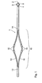
- FIG. 1 shows that section of a single lead electrode line 1 which to be placed in a heart.
- a distal end 2 of the electrode lead 1 and the immediately adjacent section of the electrode line 1 are intended for placement in a ventricle of a heart.
- the electrode line 1 has a tip electrode 3, one in ring electrode 4 located near the tip electrode and so-called Tines 5 for anchoring the lead in the myocardium of the ventricle.
- a heart On the distal section of the electrode lead intended for placement in the ventricle 1 is followed by a section 10 for placement in the atrium a heart is provided.
- the electrode line 1 divided into two strands 11 and 12.
- the two strands 11 and 12 unite at a proximal end 13 of the two-part section 10 to a single electrode line, for example to one implantable pacemaker leads.
- At the distal end 14 of the two-part Section 10 combines the two strands 11 and 12 to form that distal Section of the electrode line 1, which is for the arrangement in the ventricle is trained.
- the two strands 11 and 12 each carry two ring electrodes 15, the Stimulation of the myocardium in the area of the atrium.
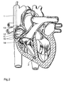
- the two strands 11 and 12 are biased against each other in such a way that in the implanted state, in particular in the area of the electrodes 15 diametrically opposed walls of the atrium are pressed, as shown in Figure 2.
- the two strands 11 and 12 of the electrode line 1 are in the implanted state - apart from the transition areas at 13 and 14 - convex outwards to make a good one ensure electrical contact of the ring electrodes 15 to the atrial myocardium and at the same time the electrode line 1 in the atrium only through the Fix preforming.
- the good holding function of the two-part section of the electrode line on the atrial myocardium and therefore good electrical contact the two strands 11 and 12 located ring electrodes 15 with the atrial Myocardium is realized by the outwardly curved strands 11 and 12, which at the diametrically opposite points in the atrium Are clamped due to their mutual bias.
- the elasticity properties the strands 11 and 12 are chosen in such a way that ensures is that the electrical contact of the electrodes 15 with the atrial Myocardium is guaranteed permanently.
- the two-part section can also be designed such that only one one or more electrodes 15 of the two strands 11 and 12 are provided become.
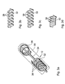
- FIGS. 3a to d show an embodiment variant in a detailed representation the electrode lead, which is stretched into the atrium of the heart can be introduced and after its introduction according to the invention Can take shape.
- the electrode line section 10 in FIG. 3 comprises a sheath 30 (in FIG 3a only indicated) as well as a metal coil 32 and within the shell 30 one arranged in a lumen enclosed by the metal coil 32 Tendon 34 at its distal end via a connecting plate 36 the metal coil 32 is connected.
- FIG. 3b shows a section of the metal coil 32 in a top view
- the 3c shows the section of the metal helix 32 in a side view.
- the individual turns of the metal coil 32 from each other are spaced apart and that the strip material from which the metal coil 32 exists, is made wider at points 38.
- By train on the Tendon 34 shortens the metal helix 32 to the turns of the metal helix 32 abut each other; see figure 3d. Since the tape material of the Metal helix 32 is widened at points 38, keeps the shortened or compressed metal helix 32 not its elongated shape, but assumes the bend shown in Figure 3d.
- the coils can correspond to the metal coils 32 be designed so that an electrode line is introduced by pulling on an Tendon takes any three-dimensional curvature. Without train on the tendon the electrode lead is stretched and flexible and can easily inserted into the blood vessel, as indicated in Figure 3a.
- a single electrode probe like the one shown typically has one (not shown here) electrode plug at its proximal end in order the electrode lead with a therapy device such as a pacemaker connect to.
- a therapy device such as a pacemaker connect to.
- the electrode plug preferably has a clamp or crimping device. The tendon becomes accordingly tightened or tightened after implantation of the electrode lead and in tightened state fixed in the area of the electrode connector.
Abstract
Description
Die Erfindung betrifft eine Einzel-Elektrodensonde für Herzschrittmachersysteme, insbesondere für DDD-Herzschrittmachersysteme mit einer Elektrodenleitung, die einen zweigeteilten Abschnitt aufweist, an dessen Beginn sich ein Elektrodenleitungsstrang in zwei Stränge aufteilt, welche sich am Ende des Abschnittes wieder zu einem Strang vereinen, wobei wenigstens einer der Stränge mindestens eine Elektrode zur Abgabe elektrischer Energie an angrenzendes Myokard aufweist.The invention relates to a single electrode probe for pacemaker systems, especially for DDD pacemaker systems with an electrode lead, which has a two-part section, at the beginning an electrode line strand is divided into two strands, which are on Join the end of the section back into a strand, at least one of the strands has at least one electrode for delivering electrical energy adjacent myocardium.
Nach Erkenntnissen der Herzschrittmachertechnik wird bei einschlägigen pathologischen Befunden die Anwendung von so genannten DDD-Herzschrittmachersystemen empfohlen. Diese Spezifikation "DDD" (= Dual pacing/Dual sensing/Demand + Triggered) bedeutet, dass einerseits eine Stimulation ("Pacing") in beiden Herzkammern vorgenommen wird und dass andererseits noch vorhandene Eigenaktionen des Sinus- bzw. AV-Knotens des Herzens sowohl im Atrium als auch im Ventrikel erfasst werden ("Sensing"). Zu diesem Zweck sind bereits so genannte "Double-Lead"-DDD-Schrittmachersysteme bekannt. Deren Hauptnachteile ist es jedoch, dass zwei getrennte Elektrodensonden in das Herz implantiert und dort positioniert werden müssen.According to the knowledge of pacemaker technology, relevant pathological findings the use of so-called DDD pacemaker systems recommended. This specification "DDD" (= Dual pacing / dual sensing / demand + triggered) means that on the one hand a Stimulation ("pacing") is done in both ventricles and that on the other hand, existing own actions of the sinus or AV node of the heart are sensed in both the atrium and the ventricle ("sensing"). For this purpose, so-called "double lead" DDD pacemaker systems are already available known. However, their main drawbacks are that two separate electrode probes are implanted in the heart and positioned there Need to become.
Es sind ferner Einzelsonden bekannt, bei denen eine ventrikuläre Elektrode an der Sondenspitze und zwei atrialen Ringelektroden in entsprechender Entfernung von der Ventrikelelektrode am Sondenkörper angeordnet sind. Die atrialen Ringelektroden werden dazu verwendet, das atriale Potential zu erfassen, wodurch die ventrikuläre Stimulation nach einer geeigneten atrioventrikulären Verzögerung getriggert wird. Die ventrikuläre Stimulation kann bipolar erfolgen. Grundsätzlich ist es zwar denkbar, die vorstehend erörterte Einzel-Elektrodensonde auch für DDD-Herzschrittmachersysteme einzusetzen. Jedoch tritt hier ein Problem auf, dass die atrialen Ringelektroden nicht wandständig platziert sind, sondern frei in Blutstrom schwimmen. Diese sogenannten "flottierenden" Elektroden im Atrium führen zu erheblichen Einschränkungen der Stimulationseigenschaften, da meist sehr hohe Stimulationsamplituden benutzt werden müssen. Der Hauptgrund hierfür ist die fehlende Wandständigkeit der flottierenden Elektroden. Die hohen Stimulationsamplituden bringen den Nachteil eines hohen Energieverbrauches und häufiger Phrenikus-Stimulationen mit sich.Single probes are also known in which a ventricular electrode at the tip of the probe and two atrial ring electrodes in the corresponding Distance from the ventricular electrode are arranged on the probe body. The atrial ring electrodes are used to measure the atrial potential detect what causes ventricular pacing after an appropriate atrioventricular Delay is triggered. Ventricular pacing can done bipolar. In principle, it is conceivable to use the one discussed above Single electrode probe can also be used for DDD pacemaker systems. However, a problem arises here that the atrial ring electrodes do not are placed on the wall, but float freely in the bloodstream. These so-called "Floating" electrodes in the atrium lead to considerable restrictions the stimulation properties, since mostly very high stimulation amplitudes must be used. The main reason for this is the lack Wall integrity of the floating electrodes. The high stimulation amplitudes bring the disadvantage of high energy consumption and more often Phrenic stimulation with itself.
EP 0 779 079 offenbart demgegenüber eine Einzel-Elektrodensonde (Single-Lead), der auf ihrer im implantierten Zustand im Vorhof platzierten Teillänge eine solche Form gegeben wird, dass mindestens eine atriale Elektrode - üblicherweise eine Ringelektrode - der Sonde an der Vorhofwand des Herzens wandständig anlegbar ist. Um dies zu erreichen, ist die Sonde auf der genannten Teillänge mit einem elastischen Vorformelement vorgesehen, welches der Sonde dort eine definiert ausgelenkte Form gibt. Auf Grund seiner Elastizität kann das Vorformelement jedoch aus seiner definierten Gestalt in einen im Wesentlichen geradlinigen gestreckten Zustand übergeführt werden, was mithilfe des üblichen, bei der Sondenimplantation verwendeten Führungsdraht erfolgt. Der Führungsdraht muss dabei in seinen Elastizitätseigenschaften natürlich signifikant steifer sein als das Vorformelement.In contrast, EP 0 779 079 discloses a single electrode probe (single lead), the part length of the implanted state in the atrium is given such a shape that at least one atrial electrode - usually a ring electrode - the probe on the atrial wall of the heart is wall-mounted. To achieve this, the probe is on the provided partial length with an elastic preform element, which gives the probe a defined deflected shape there. Because of his However, the preform element can be elastic from its defined shape converted to a substantially rectilinear stretched condition be what using the usual, used in probe implantation Guidewire is done. The guidewire must have elasticity properties of course, be significantly stiffer than the preform element.
Beim Implantationsvorgang wird vor der eigentlichen Implantation der Sonde der Führungsdraht bis zum Anschlag an die Sondenspitze vorgeschoben, wobei durch diesen Vorschub des Führungsdraht eine Zugkraft auf den Sondenkörper ausgeübt wird, die zu einer Streckung der Sonde im Bereich des Vorformelementes führt. In diesem gestreckten Zustand kann dann die Sonde in das Herz eingeführt werden. Nach der Implantierung der Sonde und dem Herausziehen des Führungsdrahtes wird die Sonde dann auf der besagten Teillänge durch das Vorformelement so ausgelegt, dass die Sonde mit mindestens einer atrialen Ringelektrode an der Vorhofwand des Herzens anliegt. Nachteilig hierbei erweist sich die relativ komplizierte Ausführung dieser Einzel-Elektrodensonde. Ferner ist eine Verwendung eines Führungsdrahtes bei der Implantation der Einzel-Elektrodensonde nicht wünschenswert.During the implantation process, the probe is actually implanted the guide wire is pushed all the way to the tip of the probe, with this feed of the guide wire a tensile force on the probe body is exercised, which leads to a stretching of the probe in the area of the Preform element leads. In this stretched state, the probe can then be introduced into the heart. After implanting the probe and pulling out the guide wire, the probe is then on said Partial length designed by the preform element so that the probe with at least one atrial ring electrode on the atrial wall of the heart is applied. A disadvantage here is the relatively complicated design this single electrode probe. Further use of a guidewire not desirable when implanting the single electrode probe.
Aus EP 0 426 089 ist eine Elektrodenanordnung mit zwei getrennten Elektrodensonden bekannt, wobei eine der Elektrodensonden in das Atrium und weiter ins Ventrikel eingeführt wird, während die andere Elektrodensonde als Gegenelektrode außen am Herzen, d. h. als endocardiale Gegenelektrode, angebracht wird. Am distalen Ende der Elektrodenleitung ist eine Helix-Elektrode 25 als Spitzenelektrode vorgesehen, die in dem rechten ventrikulären Myokard befestigt wird, indem sie dort eingeschraubt wird. Oberhalb der Spitzenelektrode ist ein Abschnitt der Leitung zweigeteilt ausgeführt, wobei beide Stränge des geteilten Abschnittes jeweils eine Wendelelektrode 22, 24 zur Defibrillation aufweisen. Die beiden Verzweigungen sind gegeneinander vorgespannt, so dass sie im implantierten Zustand voneinander beabstandet angeordnet sind. Die Elektroden 22, 24 sollen dabei einen Kontakt mit dem rechten ventrikulären Myokard bilden. Die zweigeteilte Elektrodenleitung und deren Elektroden 22, 24 wurden hier gewählt, um mit den endocardialen Elektroden 18, 20 ein vierseitiges Polygon (orthogonal electrode placement) zu bilden. Nachteilig ist hierbei jedoch, dass zwei getrennte Elektrodensonden implantiert werden müssen. Ferner ist die Elektrodenleitung nur im Ventrikel ausreichend befestigt, so dass die sich im Atrium befindlichen Elektroden als flottierende Elektroden ausgebildet sind. Ein elektrischer Kontakt der Spritzenelektrode im Ventrikel kann ohne weiteres sichergestellt werden, während der elektrische Kontakte im Atrium kritisch sein kann und somit die oben beschriebenen Nachteile aufweist. Ferner sind für die Befestigung von Elektroden im Atrium andere Voraussetzungen gegeben als zur Befestigung von Elektroden im Ventrikel, da es sich bei dem Atrium im Wesentlichen um einen "Durchgang" handelt.EP 0 426 089 describes an electrode arrangement with two separate electrode probes known, one of the electrode probes in the atrium and is inserted further into the ventricle, while the other electrode probe than Counter electrode on the outside of the heart, i. H. as an endocardial counter electrode, is attached. At the distal end of the electrode lead is a helix electrode 25 provided as a tip electrode in the right ventricular Myocardium is attached by screwing it in there. Above the Tip electrode is a section of the line in two parts, wherein both strands of the divided section each have a spiral electrode 22, 24 for defibrillation. The two branches are against each other biased so that they are spaced apart when implanted are arranged. The electrodes 22, 24 are intended to make contact with the right ventricular myocardium. The two-part electrode line and whose electrodes 22, 24 were chosen here to deal with the endocardial Electrodes 18, 20 a four-sided polygon (orthogonal electrode placement) to build. The disadvantage here, however, is that two separate electrode probes need to be implanted. Furthermore, the electrode line is only in the Ventricle adequately attached so that the electrodes are in the atrium are designed as floating electrodes. An electrical contact the syringe electrode in the ventricle can be easily secured while the electrical contacts in the atrium can be critical and thus has the disadvantages described above. Also for attachment of electrodes in the atrium are different from those for Attach electrodes in the ventricle, since it is essentially the atrium is a "passage".
Außerdem zeigt eine Figur 4f der US 4,154,247 eine Elektrodenleitung mit einem verzweigten Abschnitt 620, der der Abbildung gemäß zur Platzierung im Ventrikel vorgesehen ist, der gemäß der Beschreibung aber auch im Atrium des Herzens platziert sein kann. Die US 4,154,247 sagt jedoch nichts zur Fixierung der Elektrodenleitung.FIG. 4f of US Pat. No. 4,154,247 also shows an electrode line a branched section 620 that is shown for placement is provided in the ventricle, but also in the atrium as described of the heart. However, US 4,154,247 says nothing Fixation of the electrode lead.
Aufgabe der Erfindung ist es, eine im Atrium eines Herzens zu fixierenden Elektrodenleitung anzugeben.The object of the invention is to be fixed in the atrium of a heart Specify electrode lead.
Erfindungsgemäß wird diese Aufgabe durch eine Einzel-Elektrodensonde der eingangs genannten Art gelöst, bei der der zweigeteilte Abschnitt auf der Elektrodenleitung angeordnet und ausgestaltet ist, der Elektrodenleitung im implantierten Zustand Halt im Atrium eines Herzens zu verschaffen.According to the invention, this object is achieved by a single electrode probe solved the type mentioned, in which the two-part section on the Electrode line is arranged and configured, the electrode line in the implanted state to provide support in the atrium of a heart.
Ein derartig zweigeteilter Abschnitt der Elektrodenleitung trägt wesentlich zur Verbesserung des Haltes von Elektroden am atrialen Myokard bei, ohne dabei die Ausgestaltung der Elektrodenleitung wesentlich zu komplizieren.Such a two-part section of the electrode line contributes significantly Improve the retention of electrodes on the atrial myocardium without doing so to complicate the design of the electrode line significantly.
Bei einer weiteren Ausführungsform der Erfindung sind jeweils zwei Ringelektroden an den jeweiligen Strängen des zweigeteilten Abschnittes der Elektrodenleitung angeordnet.In a further embodiment of the invention, there are two ring electrodes on the respective strands of the two-part section of the Electrode line arranged.
Bei einer bevorzugten Ausführungsform der Erfindung verlaufen die beiden Stränge des zweigeteilten Abschnittes der Elektrodenleitung parallel zueinander und sind derart vorgeformt, dass sie sich konvex nach außen wölben, um im implantierten Zustand diametral gegenüberliegend mitsamt der Ringelektroden gegen das atriale Myokard gedrückt zu werden.In a preferred embodiment of the invention, the two run Strands of the two-part section of the electrode line parallel to each other and are pre-shaped so that they curve convexly outwards, around diametrically opposite together with the ring electrodes in the implanted state to be pressed against the atrial myocardium.
Bei einer weiteren Ausführungsform der Erfindung ist nur an einem der beiden Stränge des zweigeteilten Abschnittes zumindest eine Ringelektrode vorgesehen. In a further embodiment of the invention, only one of the two Strands of the two-part section at least one ring electrode intended.
Eine weitere Ausführungsvariante besteht in einer Elektrodenleitung, die eine versteifende Wendel aus elastischem Material besitzt, welche in einer Vielzahl von Windungen gebildet wird. Im Lumen dieser Elektrodenleitung ist eine Sehne vorgesehen, die mit ihrem distalen Ende an der Elektrodenleitung befestigt ist. Durch Zug an der Sehne ergibt sich auf diese Weise eine stauchende Kraft in der Elektrodenleitung. Die Wendel ist so ausgebildet, dass die Elektrodenleitung bei Zug auf der Sehne aus ihrer Längsrichtung ausbiegt und eine vorgegebene dreidimensionale Form annimmt. Beim Einsatz entsprechender Materialien kann diese Form fixiert werden, so dass die Elektrodenleitung die dreidimensionale Verformung beibehält, wenn der Zug über die Sehne nachlässt. Eine derartige Ausgestaltung der Elektrodenleitung kann alternativ oder zusätzlich zum vorgenannten Vorformen der Elektrodenleitung vorgesehen sein. Zum Fixieren der Sehne unter Zug kann beispielsweise im Bereich eines Elektrodensteckers am proximalen Ende der Elektrodenleitung eine Klammerung oder Crimpung vorgesehen sein. Die Sehne wird dementsprechend nach der Implantation der Elektrodenleitung angezogen oder gestrafft um im angezogenen Zustand im Bereich des Elektrodensteckers fixiert. Mit einer derartigen Elektrodenleitung lassen sich größere Krümmungskräfte erzielen, als mit einer lediglich vorgeformten Elektrodenleitung.Another embodiment variant consists in an electrode line, the one stiffening coil made of elastic material, which in a variety is formed by turns. In the lumen of this electrode line is a tendon is provided, which has its distal end on the electrode lead is attached. By pulling on the tendon this results in a compressive force in the electrode lead. The helix is designed that the electrode lead pulls on the tendon from its longitudinal direction bends and takes a predetermined three-dimensional shape. When using appropriate materials, this shape can be fixed so that the Electrode lead maintains the three-dimensional deformation when the train over the tendon. Such an embodiment of the electrode line can alternatively or additionally to the aforementioned preforming of the electrode line be provided. For example, to fix the tendon under tension in the area of an electrode connector at the proximal end of the Clamping or crimping can be provided in the electrode line. The Accordingly, tendon becomes after the implantation of the electrode lead tightened or tightened around in the tightened state in the area of the electrode connector fixed. With such an electrode line, larger ones can be obtained Achieve curvature forces than with a merely preformed electrode lead.
Eine andere Ausführungsform zeichnet sich durch ein Memorymetallelement im zu verformenden Bereich der Elektrodenleitung aus, welches beispielsweise eine an sich bekannte Titanlegierung aufweist, die bei Überschreiten einer Auslösetemperatur ihre Form von einer ersten zu einer zweiten Form verändert. Dieses Memorymetallelement ist so ausgeführt, dass seine erste Form einer im Wesentlichen gestreckten Elektrodenleitung entspricht, die ein einfaches Einführen der Elektrodenleitung erlaubt, während die zweite Form des Memorymetalls nach Überschreiten der Auslösetemperatur zu einer erfindungsgemäß verformten Elektrodenleitung führt. Vorteilhafter Weise kann ein Heizelement zum Erwärmen des Memorymetallelementes auf die Auslösetemperatur vorgesehen sein, falls die Körpertemperatur nicht ausreicht, um die Auslösetemperatur zu erreichen. Falls die Körpertemperatur ausreicht, um die Auslösetemperatur zu erreichen, bei der das Memorymetall seine Form verändert, können Kühlmittel vorgesehen sein, alternativ können die Elektrodenleitungen auch im gekühlten Zustand eingeführt werden, so dass es sich während und nach dem Einführen in das Blutgefäß langsam erwärmt und schließlich die Auslösetemperatur erreicht.Another embodiment is characterized by a memory metal element in the area of the electrode line to be deformed, which, for example has a titanium alloy known per se, which if exceeded a trigger temperature their shape from a first to a second shape changed. This memory metal element is designed to be its first Form corresponds to a substantially elongated electrode line that a easy insertion of the electrode lead allowed while the second form of the memory metal after exceeding the trigger temperature to an inventive deformed electrode lead. Can advantageously a heating element for heating the memory metal element to the trigger temperature be provided if the body temperature is not sufficient, to reach the trigger temperature. If the body temperature is sufficient, to reach the trigger temperature at which the memory metal its shape changes, coolants can be provided, alternatively the electrode lines are also inserted in the cooled state, so that it is slow during and after insertion into the blood vessel warmed and finally reached the trigger temperature.
Die Erfindung soll nun anhand von Ausführungsbeispielen mithilfe der Figuren näher erläutert werden. Diese zeigen:
Figur 1- ein zum Platzieren im Herzen vorgesehenes distales Ende einer Elektrodenleitung;
Figur 2- der in
Figur 1 abgebildete Abschnitt der Elektrodenleitung platziert in einem Herzen. - Figuren 3a bis d
- ein Ausführungsdetail einer Elektrodenleitung die durch Stauchen einer versteifenden Wendel verformbar ist;
- Figure 1
- a distal end of an electrode lead intended for placement in the heart;
- Figure 2
- the section of the electrode line shown in FIG. 1 placed in a heart.
- Figures 3a to d
- an embodiment detail of an electrode line which is deformable by upsetting a stiffening coil;
Figur 1 zeigt jenen Abschnitt einer Single-Lead-Elektrodenleitung 1, welcher
zum Platzieren in einem Herzen gedacht ist. Ein distales Ende 2 der Elektrodenleitung
1 sowie der unmittelbar daran anschließende Abschnitt der Elektrodenleitung
1 sind zum Platzieren in einem Ventrikel eines Herzens vorgesehen.
Dazu weist die Elektrodenleitung 1 eine Spitzenelektrode 3, eine in
der Nähe der Spitzenelektrode befindliche Ringelektrode 4 und so genannte
Tines 5 zum Verankern der Elektrodenleitung im Myokard des Ventrikels auf.FIG. 1 shows that section of a single
An den zum Platzieren im Ventrikel vorgesehen, distalen Abschnitt der Elektrodenleitung
1 schließt sich ein Abschnitt 10 an, der zum Platzieren im Atrium
eines Herzens vorgesehen ist. Im Bereich des Abschnitts 10 ist die Elektrodenleitung
1 in zwei Stränge 11 und 12 aufgeteilt. Die beiden Stränge 11
und 12 vereinigen sich an einem proximalen Ende 13 des zweigeteilten Abschnitts
10 zu einer einzigen Elektrodenleitung, die beispielsweise zu einem
implantierbaren Schrittmacher führt. Am distalen Ende 14 des zweigeteilten
Abschnitts 10 vereinigen sich die beiden Stränge 11 und 12 zu jenem distalen
Abschnitt der Elektrodenleitung 1, der für die Anordnung im Ventrikel
ausgebildet ist. On the distal section of the electrode lead intended for placement in the
Die beiden Stränge 11 und 12 tragen jeweils zwei Ringelektroden 15, die der
Stimulation des Myokards im Bereich des Atriums dienen sollen.The two
Die beiden Stränge 11 und 12 sind derart gegeneinander vorgespannt, dass
sie im implantierten Zustand insbesondere im Bereich der Elektroden 15
diametral einander gegenüberliegende Wände des Atriums gedrückt werden,
wie dies in Figur 2 dargestellt ist. Die beiden Stränge 11 und 12 der Elektrodenleitung
1 sind im implantierten Zustand - abgesehen von den Übergangsbereichen
bei 13 und 14 - konvex nach außen gewölbt, um einen guten
elektrischen Kontakt der Ringelektroden 15 zum atrialen Myokard sicherzustellen
und gleichzeitig die Elektrodenleitung 1 im Atrium allein durch die
Vorformung zu fixieren.The two
Im Gegensatz zu den Befestigungsmöglichkeiten einer Elektrodenleitung im Ventrikel, welche beispielsweise anhand einer Spitzenelektrode an dem ventrikulären Myokard befestigt werden kann, ist dies im Atrium nicht möglich, da es sich bei dem Atrium im Wesentlichen um einen "Durchgang" handelt. Eine Befestigung an dem atrialen Myokard ist mittels einer Spitzenelektrode nicht möglich, da die Elektrodenleitung lediglich durch das Atrium in das Ventrikel eingeführt wird.In contrast to the mounting options for an electrode cable in the Ventricles, which, for example, using a tip electrode on the ventricular myocardium, this is not possible in the atrium, since the atrium is essentially a "passage". Attachment to the atrial myocardium is by means of a tip electrode not possible because the electrode lead only through the atrium into the Ventricle is inserted.
Die gute Haltefunktion des zweigeteilten Abschnittes der Elektrodenleitung
am atrialen Myokard und damit ein guter elektrischer Kontakt der sich auf
den beiden Strängen 11 und 12 befindlichen Ringelektroden 15 mit dem atrialen
Myokard wird durch die nach außen gewölbten Stränge 11 und 12 realisiert,
welche an den diametral gegenüberliegenden Punkten im Atrium auf
Grund ihrer gegenseitigen Vorspannung aufgespannt sind. Die Elastizitätseigenschaften
der Stränge 11 und 12 sind dabei derart gewählt, dass sichergestellt
wird, dass der elektrische Kontakt der Elektroden 15 mit dem atrialen
Myokard dauerhaft gewährleistet wird.The good holding function of the two-part section of the electrode line
on the atrial myocardium and therefore good electrical contact
the two
Alternativ zu dem vorstehend beschriebenen Ausführungsbeispiel kann der
zweigeteilte Abschnitt auch derart ausgestaltet werden, dass nur an einem
der beiden Stränge 11 und 12 eine oder mehrere Elektroden 15 vorgesehen
werden. As an alternative to the exemplary embodiment described above, the
two-part section can also be designed such that only one
one or
Die Figuren 3a bis d zeigen in einer Detaildarstellung eine Ausführungsvariante der Elektrodenleitung, die in gestreckter Form in das Atrium des Herzens eingeführt werden kann und nach dem Einführen ihre erfindungsgemäße Form annehmen kann.FIGS. 3a to d show an embodiment variant in a detailed representation the electrode lead, which is stretched into the atrium of the heart can be introduced and after its introduction according to the invention Can take shape.
Der Elektrodenleitungsabschnitt 10 in Figur 3 umfasst eine Hülle 30 (in Figur
3a nur angedeutet) sowie innerhalb der Hülle 30 eine Metallwendel 32 und
eine in einem von der Metallwendel 32 eingeschlossenen Lumen angeordnete
Sehne 34 die an ihrem distalen Ende über eine Verbindungsplatte 36 mit
der Metallwendel 32 verbunden ist.The
Die Figur 3b zeigt einen Abschnitt der Metallwendel 32 in der Draufsicht; die
Figur 3c den Abschnitt der Metallwendel 32 in der Seitenansicht. Zu erkennen
ist, dass die einzelnen Windungen der Metallwendel 32 voneinander
beabstandet sind und dass das Bandmaterial, aus dem die Metallwendel 32
besteht, an den Stellen 38 jeweils breiter ausgeführt ist. Durch Zug auf die
Sehne 34 verkürzt sich die Metallwendel 32 bis die Windungen der Metallwendel
32 aneinander anliegen; siehe Figur 3d. Da das Bandmaterial der
Metallwendel 32 an den Stellen 38 jeweils verbreitert ist, behält die verkürzte
oder gestauchte Metallwendel 32 nicht ihre längsgestreckte Form, sondern
nimmt die in Figur 3d dargestellte Biegung an. Nach dem in Figur 3 dargestellten
Prinzip können die Wendeln entsprechend der Metallwendel 32 so
gestaltet werden, dass eine Elektrodenleitung durch Zug auf eine eingebrachte
Sehne beliebige dreidimensionale Krümmungen annimmt. Ohne Zug
auf die Sehne ist die Elektrodenleitung gestreckt und biegeweich und kann
leicht in das Blutgefäß eingeführt werden, wie dies in Figur 3a angedeutet ist.FIG. 3b shows a section of the
Eine Einzel-Elektrodensonde wie die dargestellte besitzt üblicherweise einen (hier nicht abgebildeten) Elektrodenstecker an ihrem proximalen Ende, um die Elektrodenleitung mit einem Therapiegerät wie einem Herzschrittmacher zu verbinden. Zum Fixieren der Sehne unter Zug kann beispielsweise im Bereich eines solchen Elektrodensteckers eine Klammerung oder Crimpung vorgesehen sein. Der Elektrodenstecker weist entsprechend vorzugsweise eine Klammer- oder Crimpeinrichtung auf. Die Sehne wird dementsprechend nach der Implantation der Elektrodenleitung angezogen oder gestrafft und im angezogenen Zustand im Bereich des Elektrodensteckers fixiert.A single electrode probe like the one shown typically has one (not shown here) electrode plug at its proximal end in order the electrode lead with a therapy device such as a pacemaker connect to. To fix the tendon under tension, for example in Area of such an electrode connector a stapling or crimping be provided. Accordingly, the electrode plug preferably has a clamp or crimping device. The tendon becomes accordingly tightened or tightened after implantation of the electrode lead and in tightened state fixed in the area of the electrode connector.
Claims (6)
Applications Claiming Priority (2)
| Application Number | Priority Date | Filing Date | Title |
|---|---|---|---|
| DE10142834A DE10142834A1 (en) | 2001-08-23 | 2001-08-23 | Single electrode probe for pacemaker systems |
| DE10142834 | 2001-08-23 |
Publications (3)
| Publication Number | Publication Date |
|---|---|
| EP1285678A2 true EP1285678A2 (en) | 2003-02-26 |
| EP1285678A3 EP1285678A3 (en) | 2003-07-23 |
| EP1285678B1 EP1285678B1 (en) | 2005-07-20 |
Family
ID=7697359
Family Applications (1)
| Application Number | Title | Priority Date | Filing Date |
|---|---|---|---|
| EP02090297A Expired - Lifetime EP1285678B1 (en) | 2001-08-23 | 2002-08-21 | Single electrode lead for pacemaker systems |
Country Status (4)
| Country | Link |
|---|---|
| US (1) | US7047086B2 (en) |
| EP (1) | EP1285678B1 (en) |
| AT (1) | ATE299734T1 (en) |
| DE (2) | DE10142834A1 (en) |
Families Citing this family (10)
| Publication number | Priority date | Publication date | Assignee | Title |
|---|---|---|---|---|
| US7899555B2 (en) * | 2006-04-11 | 2011-03-01 | Pacesetter, Inc. | Intrapericardial lead |
| US8050773B2 (en) * | 2008-09-28 | 2011-11-01 | Jie Zhu | Expandable neuromodular stimulation lead |
| JP2011159470A (en) * | 2010-01-29 | 2011-08-18 | Fujitsu Component Ltd | Male connector, female connector, and connector |
| US9775991B1 (en) | 2011-10-11 | 2017-10-03 | A-Hamid Hakki | Endovascular electrode system for tissue stimulation with embedded generator |
| US10500394B1 (en) | 2011-10-11 | 2019-12-10 | A-Hamid Hakki | Pacemaker system equipped with a flexible intercostal generator |
| US9289593B1 (en) | 2011-10-11 | 2016-03-22 | A-Hamid Hakki | Endovascular electrode system for tissue stimulation |
| US20150306375A1 (en) | 2014-04-25 | 2015-10-29 | Medtronic, Inc. | Implantable extravascular electrical stimulation lead having improved sensing and pacing capability |
| WO2016094470A1 (en) | 2014-12-09 | 2016-06-16 | Medtronic, Inc. | Extravascular implantable electrical lead having undulating configuration |
| WO2016100798A1 (en) | 2014-12-18 | 2016-06-23 | Medtronic, Inc. | Collapsible extravascular lead |
| US10391299B2 (en) | 2017-03-30 | 2019-08-27 | Medtronic, Inc. | Interventional medical systems for therapy delivery in extracardiovascular spaces and associated tools and methods |
Citations (3)
| Publication number | Priority date | Publication date | Assignee | Title |
|---|---|---|---|---|
| US4154247A (en) | 1977-04-01 | 1979-05-15 | Medtronic, Inc. | Formable cardiac pacer lead and method of assembly and attachment to a body organ |
| EP0426089A2 (en) | 1989-10-30 | 1991-05-08 | Pacesetter, Inc. | Transvenously placed defibrillation leads |
| EP0779079A1 (en) | 1995-12-15 | 1997-06-18 | BIOTRONIK Mess- und Therapiegeräte GmbH & Co Ingenieurbüro Berlin | Single electrode lead for double-chamber cardiac stimulators, especially for DD cardiac stimulators |
Family Cites Families (18)
| Publication number | Priority date | Publication date | Assignee | Title |
|---|---|---|---|---|
| EP0009732A1 (en) | 1978-10-06 | 1980-04-16 | Precimed S.A. | Catheter for a heart pace-maker |
| US4706671A (en) * | 1985-05-02 | 1987-11-17 | Weinrib Harry P | Catheter with coiled tip |
| US4660571A (en) * | 1985-07-18 | 1987-04-28 | Cordis Corporation | Percutaneous lead having radially adjustable electrode |
| US4726379A (en) * | 1985-11-14 | 1988-02-23 | Cardiac Control Systems, Inc. | Cardiac pacer with switching circuit for isolation |
| US4917104A (en) * | 1988-06-10 | 1990-04-17 | Telectronics Pacing Systems, Inc. | Electrically insulated "J" stiffener wire |
| DE4108269C2 (en) * | 1991-03-14 | 1997-04-17 | Osypka Peter | Electrode catheter |
| US5555883A (en) * | 1992-02-24 | 1996-09-17 | Avitall; Boaz | Loop electrode array mapping and ablation catheter for cardiac chambers |
| US5782239A (en) | 1992-06-30 | 1998-07-21 | Cordis Webster, Inc. | Unique electrode configurations for cardiovascular electrode catheter with built-in deflection method and central puller wire |
| FR2713492B1 (en) * | 1993-12-09 | 1996-02-16 | Microfil Ind Sa | Adjustable tubular guide, in particular for a medical and surgical device. |
| DE4342332A1 (en) | 1993-12-11 | 1995-06-14 | Bosch Gmbh Robert | Method for generating a straight-ahead signal |
| US5885278A (en) * | 1994-10-07 | 1999-03-23 | E.P. Technologies, Inc. | Structures for deploying movable electrode elements |
| US5836947A (en) * | 1994-10-07 | 1998-11-17 | Ep Technologies, Inc. | Flexible structures having movable splines for supporting electrode elements |
| US5674274A (en) * | 1995-12-14 | 1997-10-07 | Pacesetter, Inc. | Implantable adjustable single-pass A-V lead for use with an implantable stimulation device |
| SE9504675D0 (en) * | 1995-12-28 | 1995-12-28 | Pacesetter Ab | Implantable electrode cable assembly with multiple electrode contact elements |
| US5772693A (en) | 1996-02-09 | 1998-06-30 | Cardiac Control Systems, Inc. | Single preformed catheter configuration for a dual-chamber pacemaker system |
| US6076019A (en) * | 1998-08-10 | 2000-06-13 | Medtronic, Inc. | Flexible and adjustable DDD lead |
| WO2000076570A2 (en) | 1999-06-15 | 2000-12-21 | Cryocath Technologies, Inc. | Steerable catheter |
| US6500185B1 (en) * | 2000-09-29 | 2002-12-31 | Primus Medical, Inc. | Snare device |
-
2001
- 2001-08-23 DE DE10142834A patent/DE10142834A1/en not_active Withdrawn
-
2002
- 2002-08-20 US US10/224,528 patent/US7047086B2/en not_active Expired - Fee Related
- 2002-08-21 EP EP02090297A patent/EP1285678B1/en not_active Expired - Lifetime
- 2002-08-21 DE DE50203661T patent/DE50203661D1/en not_active Expired - Lifetime
- 2002-08-21 AT AT02090297T patent/ATE299734T1/en not_active IP Right Cessation
Patent Citations (3)
| Publication number | Priority date | Publication date | Assignee | Title |
|---|---|---|---|---|
| US4154247A (en) | 1977-04-01 | 1979-05-15 | Medtronic, Inc. | Formable cardiac pacer lead and method of assembly and attachment to a body organ |
| EP0426089A2 (en) | 1989-10-30 | 1991-05-08 | Pacesetter, Inc. | Transvenously placed defibrillation leads |
| EP0779079A1 (en) | 1995-12-15 | 1997-06-18 | BIOTRONIK Mess- und Therapiegeräte GmbH & Co Ingenieurbüro Berlin | Single electrode lead for double-chamber cardiac stimulators, especially for DD cardiac stimulators |
Also Published As
| Publication number | Publication date |
|---|---|
| DE50203661D1 (en) | 2005-08-25 |
| ATE299734T1 (en) | 2005-08-15 |
| EP1285678A3 (en) | 2003-07-23 |
| DE10142834A1 (en) | 2003-03-06 |
| US7047086B2 (en) | 2006-05-16 |
| EP1285678B1 (en) | 2005-07-20 |
| US20030040786A1 (en) | 2003-02-27 |
Similar Documents
| Publication | Publication Date | Title |
|---|---|---|
| DE69627290T2 (en) | Implantable electrode cable with at least one electrode contact | |
| DE60019908T2 (en) | coronary sinus | |
| DE19957241B4 (en) | Electric cable for medical purposes and system for introducing same | |
| DE69927002T2 (en) | Device for bi-atrial stimulation by means of a single electrode | |
| EP1691704B1 (en) | Electrode line for the electrotherapy of cardiac tissue | |
| DE69635402T2 (en) | Guide unit with internal guidewire made of a shape memory alloy | |
| DE602004008262T2 (en) | DESIGNING IMPLANTABLE MEDICAL LINES | |
| DE60016512T2 (en) | Implantable electrode lead | |
| DE3507119A1 (en) | ADJUSTABLE ENDOCARDIAL ELECTRODE ARRANGEMENT | |
| DE69733737T2 (en) | A-V CONVERSION WITH UNIQUE PASSAGE AS A RACE-MAKER FOR THE RIGHT VENTRICULAR ENGAGEMENT TRACK | |
| DE2929189A1 (en) | BODY STIMULATOR LINE | |
| DE3412950A1 (en) | SURGICAL ELECTRODE | |
| DE10058105A1 (en) | Medical electrical cable with variable bending stiffness | |
| EP1243286B1 (en) | Intravascular electrode lead | |
| EP0951920A2 (en) | Electrode cable for attachement to a vessel wall | |
| DE10058106A1 (en) | Medical electrical line with in the direction of the distant increasing bending stiffness | |
| EP0779079B1 (en) | Single electrode lead for double-chamber cardiac stimulators, especially for DD cardiac stimulators | |
| EP1285678B1 (en) | Single electrode lead for pacemaker systems | |
| EP2110154B1 (en) | Device for reducing the interference susceptibility of elongate impants | |
| EP2059296B1 (en) | Device for the defibrillation of the heart | |
| DE69820889T2 (en) | Management for medical purposes | |
| EP2602000A1 (en) | Implantable electrode lead | |
| CH656313A5 (en) | Electrode with an electrical conductor which is connected to a contact provided for forming a connection with tissue | |
| EP2110156B1 (en) | Field decoupling element for use with an implantable lead and implantable medical device | |
| DE19959655B4 (en) | Surgical electrode |
Legal Events
| Date | Code | Title | Description |
|---|---|---|---|
| PUAI | Public reference made under article 153(3) epc to a published international application that has entered the european phase |
Free format text: ORIGINAL CODE: 0009012 |
|
| AK | Designated contracting states |
Kind code of ref document: A2 Designated state(s): AT BE BG CH CY CZ DE DK EE ES FI FR GB GR IE IT LI LU MC NL PT SE SK TR |
|
| AX | Request for extension of the european patent |
Extension state: AL LT LV MK RO SI |
|
| PUAL | Search report despatched |
Free format text: ORIGINAL CODE: 0009013 |
|
| AK | Designated contracting states |
Designated state(s): AT BE BG CH CY CZ DE DK EE ES FI FR GB GR IE IT LI LU MC NL PT SE SK TR |
|
| AX | Request for extension of the european patent |
Extension state: AL LT LV MK RO SI |
|
| 17P | Request for examination filed |
Effective date: 20030911 |
|
| AKX | Designation fees paid |
Designated state(s): AT BE BG CH CY CZ DE DK EE ES FI FR GB GR IE IT LI LU MC NL PT SE SK TR |
|
| 17Q | First examination report despatched |
Effective date: 20040810 |
|
| GRAP | Despatch of communication of intention to grant a patent |
Free format text: ORIGINAL CODE: EPIDOSNIGR1 |
|
| GRAS | Grant fee paid |
Free format text: ORIGINAL CODE: EPIDOSNIGR3 |
|
| GRAA | (expected) grant |
Free format text: ORIGINAL CODE: 0009210 |
|
| AK | Designated contracting states |
Kind code of ref document: B1 Designated state(s): AT BE BG CH CY CZ DE DK EE ES FI FR GB GR IE IT LI LU MC NL PT SE SK TR |
|
| PG25 | Lapsed in a contracting state [announced via postgrant information from national office to epo] |
Ref country code: ES Free format text: LAPSE BECAUSE OF FAILURE TO SUBMIT A TRANSLATION OF THE DESCRIPTION OR TO PAY THE FEE WITHIN THE PRESCRIBED TIME-LIMIT Effective date: 20050720 Ref country code: FI Free format text: LAPSE BECAUSE OF FAILURE TO SUBMIT A TRANSLATION OF THE DESCRIPTION OR TO PAY THE FEE WITHIN THE PRESCRIBED TIME-LIMIT Effective date: 20050720 Ref country code: TR Free format text: LAPSE BECAUSE OF FAILURE TO SUBMIT A TRANSLATION OF THE DESCRIPTION OR TO PAY THE FEE WITHIN THE PRESCRIBED TIME-LIMIT Effective date: 20050720 Ref country code: IE Free format text: LAPSE BECAUSE OF FAILURE TO SUBMIT A TRANSLATION OF THE DESCRIPTION OR TO PAY THE FEE WITHIN THE PRESCRIBED TIME-LIMIT Effective date: 20050720 Ref country code: SK Free format text: LAPSE BECAUSE OF FAILURE TO SUBMIT A TRANSLATION OF THE DESCRIPTION OR TO PAY THE FEE WITHIN THE PRESCRIBED TIME-LIMIT Effective date: 20050720 Ref country code: CZ Free format text: LAPSE BECAUSE OF FAILURE TO SUBMIT A TRANSLATION OF THE DESCRIPTION OR TO PAY THE FEE WITHIN THE PRESCRIBED TIME-LIMIT Effective date: 20050720 Ref country code: EE Free format text: LAPSE BECAUSE OF FAILURE TO SUBMIT A TRANSLATION OF THE DESCRIPTION OR TO PAY THE FEE WITHIN THE PRESCRIBED TIME-LIMIT Effective date: 20050720 |
|
| REG | Reference to a national code |
Ref country code: GB Ref legal event code: FG4D Free format text: NOT ENGLISH |
|
| REG | Reference to a national code |
Ref country code: CH Ref legal event code: EP Ref country code: CH Ref legal event code: NV Representative=s name: BRAUNPAT BRAUN EDER AG |
|
| REG | Reference to a national code |
Ref country code: SE Ref legal event code: TRGR |
|
| GBT | Gb: translation of ep patent filed (gb section 77(6)(a)/1977) |
Effective date: 20050720 |
|
| PG25 | Lapsed in a contracting state [announced via postgrant information from national office to epo] |
Ref country code: LU Free format text: LAPSE BECAUSE OF NON-PAYMENT OF DUE FEES Effective date: 20050821 Ref country code: CY Free format text: LAPSE BECAUSE OF FAILURE TO SUBMIT A TRANSLATION OF THE DESCRIPTION OR TO PAY THE FEE WITHIN THE PRESCRIBED TIME-LIMIT Effective date: 20050821 Ref country code: AT Free format text: LAPSE BECAUSE OF NON-PAYMENT OF DUE FEES Effective date: 20050821 |
|
| REG | Reference to a national code |
Ref country code: IE Ref legal event code: FG4D Free format text: LANGUAGE OF EP DOCUMENT: GERMAN |
|
| REF | Corresponds to: |
Ref document number: 50203661 Country of ref document: DE Date of ref document: 20050825 Kind code of ref document: P |
|
| PG25 | Lapsed in a contracting state [announced via postgrant information from national office to epo] |
Ref country code: BE Free format text: LAPSE BECAUSE OF NON-PAYMENT OF DUE FEES Effective date: 20050831 Ref country code: MC Free format text: LAPSE BECAUSE OF NON-PAYMENT OF DUE FEES Effective date: 20050831 |
|
| PG25 | Lapsed in a contracting state [announced via postgrant information from national office to epo] |
Ref country code: DK Free format text: LAPSE BECAUSE OF FAILURE TO SUBMIT A TRANSLATION OF THE DESCRIPTION OR TO PAY THE FEE WITHIN THE PRESCRIBED TIME-LIMIT Effective date: 20051020 Ref country code: GR Free format text: LAPSE BECAUSE OF FAILURE TO SUBMIT A TRANSLATION OF THE DESCRIPTION OR TO PAY THE FEE WITHIN THE PRESCRIBED TIME-LIMIT Effective date: 20051020 Ref country code: BG Free format text: LAPSE BECAUSE OF FAILURE TO SUBMIT A TRANSLATION OF THE DESCRIPTION OR TO PAY THE FEE WITHIN THE PRESCRIBED TIME-LIMIT Effective date: 20051020 |
|
| PG25 | Lapsed in a contracting state [announced via postgrant information from national office to epo] |
Ref country code: PT Free format text: LAPSE BECAUSE OF FAILURE TO SUBMIT A TRANSLATION OF THE DESCRIPTION OR TO PAY THE FEE WITHIN THE PRESCRIBED TIME-LIMIT Effective date: 20051221 |
|
| REG | Reference to a national code |
Ref country code: IE Ref legal event code: FD4D |
|
| ET | Fr: translation filed | ||
| PLBE | No opposition filed within time limit |
Free format text: ORIGINAL CODE: 0009261 |
|
| STAA | Information on the status of an ep patent application or granted ep patent |
Free format text: STATUS: NO OPPOSITION FILED WITHIN TIME LIMIT |
|
| 26N | No opposition filed |
Effective date: 20060421 |
|
| BERE | Be: lapsed |
Owner name: BIOTRONIK MESS- UND THERAPIEGERATE G.M.B.H. & CO I Effective date: 20050831 |
|
| PGFP | Annual fee paid to national office [announced via postgrant information from national office to epo] |
Ref country code: NL Payment date: 20080820 Year of fee payment: 7 |
|
| PGFP | Annual fee paid to national office [announced via postgrant information from national office to epo] |
Ref country code: IT Payment date: 20080825 Year of fee payment: 7 |
|
| REG | Reference to a national code |
Ref country code: NL Ref legal event code: V1 Effective date: 20100301 |
|
| PG25 | Lapsed in a contracting state [announced via postgrant information from national office to epo] |
Ref country code: NL Free format text: LAPSE BECAUSE OF NON-PAYMENT OF DUE FEES Effective date: 20100301 |
|
| PG25 | Lapsed in a contracting state [announced via postgrant information from national office to epo] |
Ref country code: IT Free format text: LAPSE BECAUSE OF NON-PAYMENT OF DUE FEES Effective date: 20090821 |
|
| REG | Reference to a national code |
Representative=s name: RANDOLL, SOEREN, DIPL.-CHEM. UNIV. DR. RER. NA, DE Ref country code: DE Ref legal event code: R082 Ref document number: 50203661 Country of ref document: DE |
|
| REG | Reference to a national code |
Ref country code: DE Ref legal event code: R081 Ref document number: 50203661 Country of ref document: DE Owner name: BIOTRONIK SE & CO. KG, DE Free format text: FORMER OWNER: BIOTRONIK MESS- UND THERAPIEGERAETE GMBH & CO. INGENIEURBUERO BERLIN, 12359 BERLIN, DE Effective date: 20111219 |
|
| PGFP | Annual fee paid to national office [announced via postgrant information from national office to epo] |
Ref country code: GB Payment date: 20120823 Year of fee payment: 11 Ref country code: SE Payment date: 20120823 Year of fee payment: 11 |
|
| PGFP | Annual fee paid to national office [announced via postgrant information from national office to epo] |
Ref country code: FR Payment date: 20120831 Year of fee payment: 11 |
|
| REG | Reference to a national code |
Ref country code: SE Ref legal event code: EUG |
|
| GBPC | Gb: european patent ceased through non-payment of renewal fee |
Effective date: 20130821 |
|
| PG25 | Lapsed in a contracting state [announced via postgrant information from national office to epo] |
Ref country code: SE Free format text: LAPSE BECAUSE OF NON-PAYMENT OF DUE FEES Effective date: 20130822 |
|
| REG | Reference to a national code |
Ref country code: FR Ref legal event code: ST Effective date: 20140430 |
|
| PG25 | Lapsed in a contracting state [announced via postgrant information from national office to epo] |
Ref country code: GB Free format text: LAPSE BECAUSE OF NON-PAYMENT OF DUE FEES Effective date: 20130821 |
|
| PG25 | Lapsed in a contracting state [announced via postgrant information from national office to epo] |
Ref country code: FR Free format text: LAPSE BECAUSE OF NON-PAYMENT OF DUE FEES Effective date: 20130902 |
|
| PGFP | Annual fee paid to national office [announced via postgrant information from national office to epo] |
Ref country code: CH Payment date: 20160824 Year of fee payment: 15 Ref country code: DE Payment date: 20160809 Year of fee payment: 15 |
|
| REG | Reference to a national code |
Ref country code: DE Ref legal event code: R119 Ref document number: 50203661 Country of ref document: DE |
|
| REG | Reference to a national code |
Ref country code: CH Ref legal event code: PL |
|
| PG25 | Lapsed in a contracting state [announced via postgrant information from national office to epo] |
Ref country code: CH Free format text: LAPSE BECAUSE OF NON-PAYMENT OF DUE FEES Effective date: 20170831 Ref country code: LI Free format text: LAPSE BECAUSE OF NON-PAYMENT OF DUE FEES Effective date: 20170831 |
|
| PG25 | Lapsed in a contracting state [announced via postgrant information from national office to epo] |
Ref country code: DE Free format text: LAPSE BECAUSE OF NON-PAYMENT OF DUE FEES Effective date: 20180301 |