EP1285642A1 - Apparatus and software for controlling an intraoperative temperature - Google Patents
Apparatus and software for controlling an intraoperative temperature Download PDFInfo
- Publication number
- EP1285642A1 EP1285642A1 EP02025743A EP02025743A EP1285642A1 EP 1285642 A1 EP1285642 A1 EP 1285642A1 EP 02025743 A EP02025743 A EP 02025743A EP 02025743 A EP02025743 A EP 02025743A EP 1285642 A1 EP1285642 A1 EP 1285642A1
- Authority
- EP
- European Patent Office
- Prior art keywords
- wound site
- temperature
- handpiece
- infusion
- infusion fluid
- Prior art date
- Legal status (The legal status is an assumption and is not a legal conclusion. Google has not performed a legal analysis and makes no representation as to the accuracy of the status listed.)
- Withdrawn
Links
Images


Classifications
-
- A—HUMAN NECESSITIES
- A61—MEDICAL OR VETERINARY SCIENCE; HYGIENE
- A61F—FILTERS IMPLANTABLE INTO BLOOD VESSELS; PROSTHESES; DEVICES PROVIDING PATENCY TO, OR PREVENTING COLLAPSING OF, TUBULAR STRUCTURES OF THE BODY, e.g. STENTS; ORTHOPAEDIC, NURSING OR CONTRACEPTIVE DEVICES; FOMENTATION; TREATMENT OR PROTECTION OF EYES OR EARS; BANDAGES, DRESSINGS OR ABSORBENT PADS; FIRST-AID KITS
- A61F9/00—Methods or devices for treatment of the eyes; Devices for putting-in contact lenses; Devices to correct squinting; Apparatus to guide the blind; Protective devices for the eyes, carried on the body or in the hand
- A61F9/007—Methods or devices for eye surgery
- A61F9/00736—Instruments for removal of intra-ocular material or intra-ocular injection, e.g. cataract instruments
-
- A—HUMAN NECESSITIES
- A61—MEDICAL OR VETERINARY SCIENCE; HYGIENE
- A61M—DEVICES FOR INTRODUCING MEDIA INTO, OR ONTO, THE BODY; DEVICES FOR TRANSDUCING BODY MEDIA OR FOR TAKING MEDIA FROM THE BODY; DEVICES FOR PRODUCING OR ENDING SLEEP OR STUPOR
- A61M1/00—Suction or pumping devices for medical purposes; Devices for carrying-off, for treatment of, or for carrying-over, body-liquids; Drainage systems
- A61M1/71—Suction drainage systems
- A61M1/77—Suction-irrigation systems
-
- A—HUMAN NECESSITIES
- A61—MEDICAL OR VETERINARY SCIENCE; HYGIENE
- A61B—DIAGNOSIS; SURGERY; IDENTIFICATION
- A61B17/00—Surgical instruments, devices or methods, e.g. tourniquets
- A61B2017/00017—Electrical control of surgical instruments
- A61B2017/00022—Sensing or detecting at the treatment site
- A61B2017/00084—Temperature
-
- A—HUMAN NECESSITIES
- A61—MEDICAL OR VETERINARY SCIENCE; HYGIENE
- A61B—DIAGNOSIS; SURGERY; IDENTIFICATION
- A61B90/00—Instruments, implements or accessories specially adapted for surgery or diagnosis and not covered by any of the groups A61B1/00 - A61B50/00, e.g. for luxation treatment or for protecting wound edges
- A61B90/03—Automatic limiting or abutting means, e.g. for safety
- A61B2090/032—Automatic limiting or abutting means, e.g. for safety pressure limiting, e.g. hydrostatic
-
- A—HUMAN NECESSITIES
- A61—MEDICAL OR VETERINARY SCIENCE; HYGIENE
- A61M—DEVICES FOR INTRODUCING MEDIA INTO, OR ONTO, THE BODY; DEVICES FOR TRANSDUCING BODY MEDIA OR FOR TAKING MEDIA FROM THE BODY; DEVICES FOR PRODUCING OR ENDING SLEEP OR STUPOR
- A61M2205/00—General characteristics of the apparatus
- A61M2205/33—Controlling, regulating or measuring
- A61M2205/3331—Pressure; Flow
- A61M2205/3344—Measuring or controlling pressure at the body treatment site
-
- A—HUMAN NECESSITIES
- A61—MEDICAL OR VETERINARY SCIENCE; HYGIENE
- A61M—DEVICES FOR INTRODUCING MEDIA INTO, OR ONTO, THE BODY; DEVICES FOR TRANSDUCING BODY MEDIA OR FOR TAKING MEDIA FROM THE BODY; DEVICES FOR PRODUCING OR ENDING SLEEP OR STUPOR
- A61M2205/00—General characteristics of the apparatus
- A61M2205/33—Controlling, regulating or measuring
- A61M2205/3368—Temperature
Definitions
- the aspiration of emulsified tissue is aided by a saline flushing solution or irrigant that is injected into the surgical site through the small annular gap between the inside surface of the irrigating sleeve and the cutting tip.
- sensor 22 is connected to handpiece 12 and infusion fluid source 26 through irrigation lines 30, 32 and 34.
- Sensor 22 measures the flow of irrigation fluid from source 26 to handpiece 12 and supplies this information to CPU 16 through cable 36.
- the irrigation fluid flow data may be used by CPU 16 to control the operating parameters of console 14 using software commands that are well-known in the art.
- CPU 16 may open and close valve 24 so as to vary the amount of irrigation fluid reaching handpiece 12 from source 26.
- CPU 16 may also, through cable 40, vary the output of power supply 20 being sent to handpiece 12 though power cable 42.
- CPU 16 may also use data supplied by sensor 22 to vary the operation of pump 18, which aspirates fluid from handpiece 12 through line 46 and into collection container 28 through line 48.
- Infusion valve 524 can be any commercially available pinch type valve commonly used in surgical instruments.
- Compression roller mechanism 553 may contain bi-directional mechanical rollers 554 and suitable fixturing specifically designed to compress compliant container 525 in a controlled and uniform manner such that the rate of compression is proportional to the rate of fluid expulsion.
- pressurizing source 530' includes infusion container 525', mechanism 553' pressure sensor 527' and valve 524'.
- Mechanism 553' includes compression actuators 103, upper plate 105, lower plate 107, and plate return springs 106.
- Compression actuators 103 may be either worm gear or hydraulically driven and designed to compress plate 105 in a controlled and uniform manner such that the rate of compression is proportional to the rate of fluid expulsion out of container 525'.
- Return springs 106 can be any commercially available springs used to return the plate to a previous position.
Abstract
- a. selecting a desired intraoperative wound site temperature;
- b. providing infusion fluid flow information to the control module;
- c. providing handpiece power information to the control module from the handpiece power supply;
- d. calculating a current temperature at the would site based on current and previous values of infusion fluid flow and handpiece power;
- e. comparing the calculated current temperature at the wound site with the selected desired intraoperative wound site temperature; and
- f. varying the operation of the handpiece power supply based on the comparison between the calculated current temperature at the wound site with the selected desired intraoperative wound site temperature.

Description
- This invention relates generally to the field of cataract surgery and more particularly to an infusion control system for a phacoemulsification handpiece.
- The human eye in its simplest terms functions to provide vision by transmitting light through a clear outer portion called the cornea, and focusing the image by way of the lens onto the retina. The quality of the focused image depends on many factors including the size and shape of the eye, and the transparency of the cornea and lens.
- When age or disease causes the lens to become less transparent, vision deteriorates because of the diminished light which can be transmitted to the retina. This deficiency in the lens of the eye is medically known as a cataract. An accepted treatment for this condition is surgical removal of the lens and replacement of the lens function by an artificial intraocular lens (IOL).
- In the United States, the majority of cataractous lenses are removed by a surgical technique called phacoemulsification. During this procedure, a thin phacoemulsification cutting tip is inserted into the diseased lens and vibrated ultrasonically. The vibrating cutting tip liquefies or emulsifies the lens so that the lens may be aspirated out of the eye. The diseased lens, once removed, is replaced by an artificial lens.
- A typical ultrasonic surgical device suitable for ophthalmic procedures consists of an ultrasonically driven handpiece, an attached cutting tip, and irrigating sleeve and an electronic control console. The handpiece assembly is attached to the control console by an electric cable and flexible tubings. Through the electric cable, the console varies the power level transmitted by the handpiece to the attached cutting tip and the flexible tubings supply irrigation fluid to and draw aspiration fluid from the eye through the handpiece assembly.
- The operative part of the handpiece is a centrally located, hollow resonating bar or horn directly attached to a set of piezoelectric crystals. The crystals supply the required ultrasonic vibration needed to drive both the horn and the attached cutting tip during phacoemulsification and are controlled by the console. The crystal/horn assembly is suspended within the hollow body or shell of the handpiece by flexible mountings. The handpiece body terminates in a reduced diameter portion or nosecone at the body's distal end. The nosecone is externally threaded to accept the irrigation sleeve. Likewise, the horn bore is internally threaded at its distal end to receive the external threads of the cutting tip. The irrigation sleeve also has an internally threaded bore that is screwed onto the external threads of the nosecone. The cutting tip is adjusted so that the tip projects only a predetermined amount past the open end of the irrigating sleeve. Ultrasonic handpieces and cutting tips are more fully described in U.S. Pat. Nos. 3,589,363; 4,223,676; 4,246,902; 4,493,694; 4,515,583; 4,589,415; 4,609,368; 4,869,715; 4,922,902; 4,989,583; 5,154,694 and 5,359,996.
- In use, the ends of the cutting tip and irrigating sleeve are inserted into a small incision of predetermined width in the cornea, sclera, or other location. The cutting tip is ultrasonically vibrated along its longitudinal axis within the irrigating sleeve by the crystal-driven ultrasonic horn, thereby emulsifying the selected tissue in situ. The hollow bore of the cutting tip communicates with the bore in the horn that in turn communicates with the aspiration line from the handpiece to the console. A reduced pressure or vacuum source in the console draws or aspirates the emulsified tissue from the eye through the open end of the cutting tip, the cutting tip and horn bores and the aspiration line and into a collection device. The aspiration of emulsified tissue is aided by a saline flushing solution or irrigant that is injected into the surgical site through the small annular gap between the inside surface of the irrigating sleeve and the cutting tip.
- The preferred surgical technique is to make the incision into the anterior chamber of the eye as small as possible in order to reduce the risk of induced astigmatism. These small incisions result in very tight wounds that squeeze the irrigating sleeve tightly against the vibrating tip. Friction between the irrigating sleeve and the vibrating tip generates heat, but the risk of the tip overheating and causing a burn to the tissue is reduces by the cooling effect of the aspirated fluid flowing inside the tip. When the tip becomes occluded with tissue, this aspiration flow can be reduced or eliminated, allowing the tip to heat up.
- Prior art devices have used sensors that detect large rises in aspiration vacuum, and predict occlusions based on vacuum rise. Based on this sensed occlusion, power to the handpiece may be reduced and/or irrigation and aspiration flows can be increased. See U.S. Patent Nos. 5,591,127, 5,700,240 and 5,766,146 (Barwick, Jr., et al.). Increased vacuum levels in the aspiration line, however, do not necessarily indicate that the flow of cooling fluid around the tip has been cut off. Even with the tightest incisions, some irrigating fluid will leak out between the wound and the outside of the irrigating sleeve. The wound leakage also provides additional cooling flow to the incision site, and measuring rises in aspiration vacuum alone does not necessarily indicate that a potential for a corneal burn exists. Therefore, power to the handpiece may be interrupted prematurely.
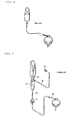
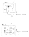
- Prior art devices have also used gravity fed methods or pressurized gas sources for controlling surgical infusion pressure and flow. Gravity feed infusion methods, such as those illustrated in FIG. 8, provide a pressure and flow based on the height of a column of liquid. The higher the column, the greater the pressure and flow. The lower the column, the lower the pressure and flow. The surgeon controls the column height by raising or lowering the infusion bottle. Pressurized gas sources, such as those illustrated in FIG. 9, control the infusion pressure by increasing or decreasing the pressure inside the infusion bottle. The bottle is suspended at a constant height and a gas pressure pump is connected to the bottle. See U.S. Patent Nos. 4, 813,927, 4,900,301, 5,032,111 and 5,047,009(Morris, et al.), the entire contents of which being incorporated herein by reference. Gravity feed methods have limitations on pressure response rates due to the requirements of raising and lowering the infusion bottle. Pressurized gas methods improve on the response rates but require cumbersome venting snorkel devices that complicate the surgical setup. Both methods require filtering of air or gas into the bottle to prevent contamination which is added cost and complexity
- Therefore, a need continues to exist for an infusion source for a surgical applications that utilizes a better method of infusion pressure and flow.
- Our European Patent No. 1,062,958 describes a method of operating a central processing unit in a control system for a surgical device having a handpiece adapted to deliver irrigation fluid from a source to, and draw aspiration fluid from, an operative site, said control system comprising a control console having a control module including the central processing unit, and an irrigation flow sensor in the control console or in the handpiece, capable of providing irrigation fluid flow data to the central processing unit. Software performs the steps of;
setting a predetermined infusion fluid flow rate in the control module,
monitoring current actual infusion fluid flow rate data measured by the irrigation flow sensor, or as calculated by the central processing unit,
comparing the current actual or calculated infusion fluid flow rate with the predetermined infusion fluid flow rate, and if below the predetermined infusion fluid flow rate,
using the fluid flow data to control the operating parameters of the surgical device with software commands to vary any one or more of; - the operation of an aspiration pump,
- the output of the handpiece power supply,
- the irrigation fluid flow through a valve,
- the output of a pressurizing source for the irrigation fluid,
- Reference is also made to our European Patent Application No. 01959592.5 from which the present application is divided.
- The present invention improves upon the prior art by providing apparatus and software for controlling an intraoperative temperature at a wound site, in accordance with claims which follow, which includes a surgical infusion system having a variety of infusion fluid pressure sensors. The system may also use a collapsible infusion container. The information provided by the infusion fluid pressure sensors allows the users to predict and control intraoperative wound site temperature.
- Accordingly, one objective of the present invention is to provide a surgical console control system. Another objective is to provide a method of operating a surgical console control system having infusion fluid pressure sensing capability.
- Another objective of the present invention is to provide software for operating a surgical console control system that provides more accurate control of intraoperative wound site temperature.
- Another objective of the present invention is to provide faster and more accurate control of infusion pressure and flow.
- These and other advantages and objectives of the present invention will become apparent from the detailed description and claims that follow.
-
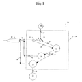
- FIG. 1 is a block diagram of a first embodiment of a control system that can be used with the present invention.
- FIG. 2 is a block diagram of a second embodiment of a control system that can be used with the present invention.
- FIG. 3 is a block diagram of a third embodiment of a control system that can be used with the present invention showing the flow sensor in the instrument and pressurized infusion control of the infusion fluid source.
- FIG. 4 is a block diagram of a fourth embodiment of a control system that can be used with the present invention showing the flow sensor in the handpiece and pressurized infusion control of the infusion fluid source.
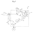
- FIG. 5 is a block diagram of a fifth embodiment of a control system that can be used with the present invention showing the flow sensor in the instrument and measuring air flow of the pressurized infusion fluid source to calculate infusion fluid flow.
- FIG. 6 is a block diagram of a sixth embodiment of a control system that can be used with the present invention showing the pressurized infusion fluid source as a compressed compliant bag and the infusion fluid flow calculated from the rate of infusion fluid source compression.
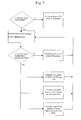
- FIG. 7 is a flow chart illustrating the operation of an infusion flow control mode that can be used with the present invention.
- FIG. 8 is an illustration of a prior art gravity fed infusion method.
- FIG. 9 is an illustration of a prior art pressurized infusion method.
- FIG. 10 is a block diagram of a one embodiment of the compliant container that can be used with the present invention being compressed between rollers.
- FIG. 11 is a block diagram of another embodiment of the compliant container that can be used with the present invention being compressed by a pressure plate.
- FIG. 12 is a block diagram of a yet another embodiment of a control system that can be used with the present invention having an irrigation line pressure sensor and pressurized infusion control of the infusion fluid source.
-
- As seen in FIG. 1,
control system 10 for use in operatinghandpiece 12 includescontrol console 14.Control console 14 generally includes control module orCPU 16,aspiration pump 18,handpiece power supply 20,irrigation flow sensor 22 andvalve 24.Console 14 may be any commercially available surgical control console such as the ACCURUS® or LEGACY® SERIES TWENTY THOUSAND® surgical systems available from Alcon Laboratories, Inc., Fort Worth, Texas.CPU 16 may be any suitable microprocessor, micro controller, computer or digital logic controller.Pump 18 may be any suitable pump, such as a peristaltic, scroll, diaphragm or venturi pump.Power supply 20 may be any suitable ultrasound driver, such as incorporated in the ACCURUS® or LEGACY® SERIES TWENTY THOUSAND® surgical systems available from Alcon Laboratories, Inc., Fort Worth, Texas.Sensor 22 may be any commercially available flow sensor, such as Models Nos. T101D or T201D available from Transonic Systems, Inc., Ithaca, New York.Valve 24 may be any suitable valve such as a solenoid-activated pinch valve.Infusion source 26 may be any commercially available irrigation solution. - In use,
sensor 22 is connected to handpiece 12 andinfusion fluid source 26 throughirrigation lines Sensor 22 measures the flow of irrigation fluid fromsource 26 tohandpiece 12 and supplies this information toCPU 16 throughcable 36. The irrigation fluid flow data may be used byCPU 16 to control the operating parameters ofconsole 14 using software commands that are well-known in the art. For example,CPU 16, throughcable 38, may open andclose valve 24 so as to vary the amount of irrigationfluid reaching handpiece 12 fromsource 26.CPU 16 may also, throughcable 40, vary the output ofpower supply 20 being sent to handpiece 12 thoughpower cable 42.CPU 16 may also use data supplied bysensor 22 to vary the operation ofpump 18, which aspirates fluid fromhandpiece 12 throughline 46 and into collection container 28 throughline 48. - As seen in FIG. 2,
control system 110 for use inoperating handpiece 112 includescontrol console 114.Control console 114 generally includes control module orCPU 116,aspiration pump 118,handpiece power supply 120 andvalve 124.Flow sensor 122 is contained withinhandpiece 112. - In use,
tip 150 is connected tofluid source 126 throughsensor 122 throughirrigation lines Sensor 122 measures the flow of irrigation fluid fromsource 126 to tip 150 and supplies this information toCPU 116 throughcable 136.CPU 116, throughcable 138, may open andclose valve 124 so as to vary the amount of irrigationfluid reaching tip 150 fromsource 126.CPU 116 may also, throughcable 140, vary the output ofpower supply 120 being sent to handpiece 112 thoughpower cable 142.CPU 116 may also use data supplied bysensor 122 to vary the operation ofpump 118, which aspirates fluid fromhandpiece 112 throughline 146 and intocollection container 128 through line 148.CPU 116 may also use data supplied bysensor 122 and the applied output ofpower supply 120 to provide audible tones to the user. - As seen in FIG. 3,
control system 210 for use inoperating handpiece 212 includescontrol console 214.Control console 214 generally includes control module orCPU 216,aspiration pump 218,handpiece power supply 220,valve 224, pressurizingsource 229, andpressure sensor 227.Flow sensor 222 is connected to handpiece 212 andinfusion fluid source 226 throughirrigation lines Infusion source 226 may be any commercially available irrigation solution provided in bottles.Pressurizing source 229 pressurizesinfusion fluid source 226 throughline 252 and is controlled byCPU 216 throughcable 250.Pressurizing source 229 may be any commercially available pressure controller, such as incorporated in the ACCURUS® surgical system available from Alcon Laboratories, Inc., Fort Worth, Texas.Pressure sensor 227 measures the pressure ofinfusion fluid source 226 throughlines 254 and is monitored byCPU 216 throughcable 256.Pressure sensor 227 may be any suitable commercially available pressure sensor, such as Model MPX5100 available from Motorola, Inc., Phoenix, Arizona. - In use,
sensor 222 measures the flow of irrigation fluid fromsource 226 tohandpiece 212 and supplies this information toCPU 216 throughcable 236. The irrigation fluid flow data may be used byCPU 216 to control the operating parameters ofconsole 214 using software commands that are well known in the art. For example,CPU 216, throughcable 250, may control pressurizingsource 229 while readingpressure sensor 227 data throughcable 256 so as to vary the pressure and amount of irrigationfluid reaching handpiece 212 fromsource 226.CPU 216 may also, throughcable 240, vary the output ofpower supply 220 being sent to handpiece 212 throughpower cable 242.CPU 216 may also use data supplied bysensor 222 to vary the operation ofpump 218 throughline 244, which aspirates fluid fromhandpiece 212 throughline 246 and intocollection container 228 throughline 248.CPU 216 may also use data supplied bysensor 222 and the applied output ofpower supply 220 to provide audible tones to the user. - As seen in FIG. 4,
control system 310 for use inoperating handpiece 312 includescontrol console 314.Control console 314 generally includes control module orCPU 316,aspiration pump 318,handpiece power supply 320,valve 324, pressurizingsource 329, andpressure sensor 327.Flow sensor 322 is contained withinhandpiece 312.Infusion source 326 may be any commercially available irrigation solution provided in bottles.Pressurizing source 329 may be any commercially available pressure controller.Pressure sensor 327 may be any suitable commercially available pressure sensor. - In use,
sensor 322 measures the flow of irrigation fluid fromsource 326 tohandpiece 312 and supplies this information toCPU 316 throughcable 336. The irrigation fluid flow data may be used byCPU 316 to control the operating parameters ofconsole 314 using software commands that are well known in the art. For example,CPU 316, throughcable 350, may control pressurizingsource 329 while readingpressure sensor 327 data throughcable 356 so as to vary the pressure and amount of irrigationfluid reaching handpiece 312 fromsource 326.CPU 316 may also, throughcable 340, vary the output ofpower supply 320 being sent to handpiece 312 throughpower cable 342.CPU 316 may also use data supplied bysensor 322 to vary the operation ofpump 318 throughcable 344, which aspirates fluid fromhandpiece 312 throughline 346 and intocollection container 328 through line 348.CPU 316 may also use data supplied bysensor 322 and the applied output ofpower supply 320 to provide audible tones to the user. - As seen in FIG. 5,
control system 410 for use inoperating handpiece 412 includescontrol console 414.Control console 414 generally includes control module orCPU 416,aspiration pump 418,handpiece power supply 420,valve 424, pressurizingsource 429, andpressure sensor 527.Airflow sensor 423 is connected to pressurizingsource 429 andinfusion fluid source 426 throughlines Sensor 423 may be any commercially available flow sensor, such as Model AWM3100V available from Honeywell Micro Switch, Freeport, Illinois.Infusion source 426 may be any commercially available irrigation solution provided in bottles. - In use,
sensor 423 measures the flow of air into theinfusion fluid source 426 and supplies this information toCPU 416 throughcable 436. The airflow data may be used byCPU 416 along with information frompressure sensor 427 for the calculation of infusion flow to the handpiece throughline 434. This infusion flow calculation may be used to control the operating parameters ofconsole 414 using software commands that are well known in the art. For example,CPU 416, throughcable 450, may control pressurizingsource 429 while readingpressure sensor 427 data throughcable 456 so as to vary the pressure and amount of irrigationfluid reaching handpiece 412 fromsource 426.CPU 416 may also, throughcable 440, vary the output ofpower supply 420 being sent to handpiece 412 throughpower cable 442.CPU 416 may also use this infusion flow calculation to vary the operation ofpump 418 throughcable 444, which aspirates fluid fromhandpiece 412 throughpower cable 442.CPU 416 may also use this infusion flow calculation to vary the operation ofpump 418 throughcable 444, which aspirates fluid fromhandpiece 412 throughline 446 and intocollection container 428 throughline 448.CPU 416 may also use this infusion flow calculation and the applied output ofpower supply 420 to provide audible tones to the user. - As seen in FIG. 6,
control system 510 for use inoperating handpiece 512 includescontrol console 514.Control console 514 generally includes control module orCPU 516,aspiration pump 518,handpiece power supply 520,valve 524, pressurizingsource 530, andpressure sensor 527.Infusion source 525 may be any commercially available irrigation solution provided in bags or a custom compliant container.Pressurizing source 530 is a compressing device that squeezesinfusion fluid source 525 throughmechanism 553 in order to pressurize the fluid. The rate of compression of the infusion fluid source is controlled byCPU 516 throughcable 550. - In use,
CPU 516 calculates the infusion flow to the handpiece throughline 534 based on the compression rate of pressurizingsource 530 and the pressure data frompressure sensor 527, it being understood thatpressure sensor 527 may communicate directly withinfusion fluid source 525 or communicate withinfusion fluid source 525 throughirrigation lines console 514 using software commands that are well known in the art. For example,CPU 516, throughcable 550, may control pressurizingsource 530 while readingpressure sensor 527 data throughcable 556 so as to vary the pressure and amount of irrigationfluid reaching handpiece 512 fromsource 525.CPU 516 may also, throughcable 540, vary the output ofpower supply 520 being sent to handpiece 512 throughpower cable 542.CPU 516 may also use this infusion flow calculation to vary the operation ofpump 518 throughcable 544, which aspirates fluid fromhandpiece 512 throughline 546 and intocollection container 528 throughline 548.CPU 516 may also use this infusion flow calculation and the applied out put ofpower supply 520 to provide audible tones to the user. - As seen in FIG. 10, pressurizing
source 530 includescompression roller mechanism 553,infusion container 525,pressure sensor 527 and infusion orirrigation valve 524.Roller mechanism 553 includescompression rollers 554 androllers driving motor 555.Infusion container 525 may be a compliant bag such as commonly supplied by Charter Medical, Lakewood, New Jersey, for surgical site infusion or a custom container specifically designed for this application.Infusion container 525 may be made from any suitable material that provides container collapse without excessive stretching.Infusion container 525 may be a thin wall bottle with or without corrugated sides (not shown).Pressure sensor 527 may be any commercially available, disposable, pressure sensor such as Model 1290C manufactured by Hewlett Packard or a custom type sensor specifically made for this application.Infusion valve 524 can be any commercially available pinch type valve commonly used in surgical instruments.Compression roller mechanism 553 may contain bi-directionalmechanical rollers 554 and suitable fixturing specifically designed to compresscompliant container 525 in a controlled and uniform manner such that the rate of compression is proportional to the rate of fluid expulsion. - In use,
compliant container 525 is placed inroller mechanism 553 and connected toirrigation line 533.Infusion valve 524 is opened and theroller mechanism 553 moves to compresscontainer 525. The movement of therollers mechanism 554 reduces the available volume incontainer 525, which forces the infusion liquid intoirrigation line 533. Information frompressure sensor 527 indicates the infusion pressure androller mechanism 553 is controlled such that a predetermined infusion pressure reading is maintained. The rate of movement of drivingmotor 555 is proportional to the rate of liquid expulsion and the information may be used bycontrol system 510 for further systematic control. - As seen in FIG. 11, pressurizing source 530' includes infusion container 525', mechanism 553' pressure sensor 527' and valve 524'. Mechanism 553' includes
compression actuators 103,upper plate 105,lower plate 107, and plate return springs 106.Compression actuators 103 may be either worm gear or hydraulically driven and designed to compressplate 105 in a controlled and uniform manner such that the rate of compression is proportional to the rate of fluid expulsion out of container 525'. Return springs 106 can be any commercially available springs used to return the plate to a previous position. - In use, compliant container 525' is placed beneath
upper plate 105 andlower plate 107 and connected toirrigation line 533. Infusion valve 524' is opened andactuators 103 operated so as to place downward pressure onplate 105 againstsprings 106. Downward pressure onplate 105 squeezes container 525' betweenupper plate 105 andlower plate 107, thereby reducing the available volume in container 525', which forces the infusion liquid into irrigation line 533'. Information from pressure sensor 527' indicates the infusion pressure andactuators 103 are controlled such that a predetermined infusion pressure reading is maintained. The rate of movement ofactuators 103 is proportional to the rate of liquid expulsion and the information may be used bycontrol system 510 for further systematic control. - As seen in FIG. 12, in an embodiment of the present invention,
control system 710 for use inoperating handpiece 712 includescontrol console 714.Control console 714 generally includes control module orCPU 716,aspiration pump 718,handpiece power supply 720,valve 724, pressurizingsource 729, and infusion fluidsource pressure sensor 727. Irrigationline pressure sensor 722 is connected to handpiece 712 andinfusion fluid source 726 throughirrigation lines Infusion source 726 may be any commercially available irrigation solution provided in bottles.Pressurizing source 729 pressurizesinfusion fluid source 726 throughline 752 and is controlled byCPU 716 throughcable 750.Pressurizing source 729 may be any commercially available pressure controller, such as incorporated in the ACCURUS® surgical system available from Alcon Laboratories, Inc., Fort Worth, Texas.Pressurizing source 729 may also be similar to pressurizingsource 530 or 530' described in FIGS. 6, 10 and 11.Pressure sensor 727 measures the pressure ofinfusion fluid source 726 throughlines 754 and is monitored byCPU 716 throughcable 756.Pressure sensors airflow sensor 423 may be used in addition to or in place ofsensor 727, and that the pressure withininfusion fluid source 726 can be derived from the operation of pressurizingsource 530 or 530'. - In use,
sensor 722 measures the pressure of the irrigation fluid inirrigation line 734 at, or even within,handpiece 712 and supplies this information toCPU 716 throughcable 736. The irrigation line pressure data may be used byCPU 716 to control the operating parameters ofconsole 714, as described below, using software commands that are well known in the art. For example,CPU 716, throughcable 750, may control pressurizingsource 729 while readingpressure sensor 727 data throughcable 756 so as to vary the pressure and amount of irrigationfluid reaching handpiece 712 fromsource 726.CPU 716 may also, throughcable 740, vary the output ofpower supply 720 being sent to handpiece 712 throughpower cable 742.CPU 716 may also use data supplied bysensor 722 to vary the operation ofpump 718 throughline 744, which aspirates fluid fromhandpiece 712 throughline 746 and intocollection container 728 throughline 748.CPU 716 may also use data supplied bysensor 722 and the applied output ofpower supply 720 to provide audible tones to the user. - As seen in FIG. 7, when the system of the present invention is monitoring infusion flow, the system monitors the current infusion flow and compares the actual flow against a predetermined flow rate. If infusion flow is above the predetermined rate, no action is taken by the system. If the infusion flow is below the predetermined rate, the system may take a variety of actions, such as changing the power delivered to the ultrasound handpiece, providing a variable tone to the surgeon or changing the aspiration pressure.
- The system of the present invention may be used to control intraoperative intraocular pressure (IOP) and/or temperature at the wound. To control IOP, the user sets a desired IOP or IOP range (IOPset) in
CPU 716. Infusion fluid line pressure information from sensor 722 (Pirr) is provided toCPU 716, and infusion fluid source pressure information fromsensor 727 is provided to CPU 716 (Pbot).CPU 716 determines the flow out ofhandpiece 712 using the equation Flow = (Pbot - Pirr)/ Rbot where Rbot is the fludics resistance betweensensor 727 andsensor 722.CPU 716 computes the actual IOP within the surgical site (IOPact) using the equation IOPact = Pirr - (Flow * Rirr) where Rirr is the fluidics resistance betweensensor 722 and the surgical site. CPU compares IOPact to IOPset and adjusts pressurizingsource 729 accordingly to maintain IOPset. The logic process inCPU 716 can be programmed in a variety of ways, such as PID algorithm, fuzzy logic algorithm or any other suitable algorithm. Alternatively, if pressurizingsource 530 or 530' is used, the flow out ofhandpiece 712 will be proportional to the rate of compression ofinfusion fluid source 726, so pressurizingsource 530 or 530' may be used to monitor infusion flow out ofhandpiece 712 andsensor 722 is not required. - The system of the present invention may also be used to control temperature at the wound site. To control wound site temperature, the user may select a wound site temperature (Tempmax) and desired action in
CPU sensor CPU CPU CPU - This description is given for purposes of illustration and explanation. It will be apparent to those skilled in the relevant art that changes and modifications may be made to the invention described above without departing from its scope.
Claims (10)
- Apparatus for controlling an intraoperative temperature at a wound site, comprising a control system having,and characterized by;i) a control console (14,114,214,314,414,514,714) having a control module including the central processing unit (16,116,216,316,416,516,716);ii) a handpiece power supply (20,120,220,320,420,520,720) andiii) a means for measuring infusion fluid flow (22,122,222,322,422,522,722);a. means for selecting a desired intraoperative wound site temperature;b. means for providing infusion fluid flow information to the control module;c. means for providing handpiece power information to the control module from the handpiece power supply;d. means for calculating a current temperature at the would site based on current and previous values of infusion fluid flow and handpiece power;e. means for comparing the calculated current temperature at the wound site with the selected desired intraoperative wound site temperature; andf. means for varying the operation of the handpiece power supply based on the comparison between the calculated current temperature at the wound site with the selected desired intraoperative wound site temperature.
- Apparatus according to claim 1, wherein the control console further includes an aspiration pump (18,118,218,318,418,518,718) and the control module is capable of varying the operation of the aspiration pump based on the calculated current wound site temperature.
- Apparatus according to claim 1, wherein the control console is capable of providing audible tones based on the calculated current wound site temperature.
- Apparatus according to claim 1, wherein the control console further includes an infusion fluid source (26,126,226,326,426,526,726) and a pressurizing source (530,530',729) for the infusion fluid source.
- Apparatus according to claim 1, wherein the infusion fluid source (26,126,226,326,426,526,726) is flexible and the pressurizing source (530,530',729) includes a mechanism (554, 553') to compress the infusion fluid source.
- Apparatus according to claim 1, wherein the means for measuring infusion flow (22,122,222,322,422,522,722) comprises a mechanism to compress the infusion fluid source.
- Apparatus according to claim 5 or claim 6, wherein the mechanism (554, 553') to compress the infusion fluid source comprises a roller mechanism (554) or a compression plate (553').
- Software which when executing on a central processing unit is configured to perform the operation of a central processing unit (16,116,216,316,416,516,716) in a control system for a surgical device having a handpiece (12,112, 212, 312, 412, 512,712) with a handpiece power supply (20,120,220,320,420,520,720), adapted to deliver infusion fluid from a source to, and draw aspiration fluid from, an operative site, said control system comprising a control console (14,114,214,314,414,514,714) having a control module including the central processing unit, and a means for measuring infusion flow (22,122,222,322,422,522,722) in the control console or in the handpiece, capable of providing infusion fluid flow data to the central processing unit,
characterized by software-implemented steps of;a. selecting a desired intraoperative wound site temperature;b. providing infusion fluid flow information to the control module;c. providing handpiece power information to the control module from the handpiece power supply;d. calculating a current temperature at the would site based on current and previous values of infusion fluid flow and handpiece power;e. comparing the calculated current temperature at the wound site with the selected desired intraoperative wound site temperature; andf. varying the operation of the handpiece power supply based on the comparison between the calculated current temperature at the wound site with the selected desired intraoperative wound site temperature. - Software according claim 8, further comprising the step of varying the operation of an aspiration pump based on the calculated current wound site temperature.
- Software according claim 8, further comprising the step of providing audible tones based on the calculated current wound site temperature.
Applications Claiming Priority (3)
| Application Number | Priority Date | Filing Date | Title |
|---|---|---|---|
| US65154100A | 2000-08-29 | 2000-08-29 | |
| US651541 | 2000-08-29 | ||
| EP01959592A EP1225854A1 (en) | 2000-08-29 | 2001-08-07 | Methods of controlling intraocular pressure and temperature |
Related Parent Applications (1)
| Application Number | Title | Priority Date | Filing Date |
|---|---|---|---|
| EP01959592A Division EP1225854A1 (en) | 2000-08-29 | 2001-08-07 | Methods of controlling intraocular pressure and temperature |
Publications (1)
| Publication Number | Publication Date |
|---|---|
| EP1285642A1 true EP1285642A1 (en) | 2003-02-26 |
Family
ID=24613239
Family Applications (2)
| Application Number | Title | Priority Date | Filing Date |
|---|---|---|---|
| EP01959592A Withdrawn EP1225854A1 (en) | 2000-08-29 | 2001-08-07 | Methods of controlling intraocular pressure and temperature |
| EP02025743A Withdrawn EP1285642A1 (en) | 2000-08-29 | 2001-08-07 | Apparatus and software for controlling an intraoperative temperature |
Family Applications Before (1)
| Application Number | Title | Priority Date | Filing Date |
|---|---|---|---|
| EP01959592A Withdrawn EP1225854A1 (en) | 2000-08-29 | 2001-08-07 | Methods of controlling intraocular pressure and temperature |
Country Status (7)
| Country | Link |
|---|---|
| EP (2) | EP1225854A1 (en) |
| JP (1) | JP2004507321A (en) |
| AU (1) | AU766716B2 (en) |
| BR (1) | BR0107148A (en) |
| CA (1) | CA2385779A1 (en) |
| IL (1) | IL149190A0 (en) |
| WO (1) | WO2002017833A1 (en) |
Cited By (6)
| Publication number | Priority date | Publication date | Assignee | Title |
|---|---|---|---|---|
| WO2007008437A1 (en) * | 2005-07-07 | 2007-01-18 | Alcon, Inc. | Surgical system |
| US8377000B2 (en) | 2010-10-01 | 2013-02-19 | Abbott Laboratories | Enteral feeding apparatus having a feeding set |
| US8377001B2 (en) | 2010-10-01 | 2013-02-19 | Abbott Laboratories | Feeding set for a peristaltic pump system |
| US8689439B2 (en) | 2010-08-06 | 2014-04-08 | Abbott Laboratories | Method for forming a tube for use with a pump delivery system |
| EP2967988A1 (en) * | 2013-03-15 | 2016-01-20 | Abbott Medical Optics Inc. | Phacoemulsification flow rate detection system and method |
| WO2018020426A1 (en) * | 2016-07-28 | 2018-02-01 | Novartis Ag | Pressure control in phacoemulsification system |
Families Citing this family (25)
| Publication number | Priority date | Publication date | Assignee | Title |
|---|---|---|---|---|
| US7645255B2 (en) * | 2004-03-22 | 2010-01-12 | Alcon, Inc. | Method of controlling a surgical system based on irrigation flow |
| US7625388B2 (en) * | 2004-03-22 | 2009-12-01 | Alcon, Inc. | Method of controlling a surgical system based on a load on the cutting tip of a handpiece |
| WO2008157674A1 (en) * | 2007-06-19 | 2008-12-24 | Yablon, Jay, R. | Post-occlusion chamber collapse canceling system for a surgical apparatus and method of use |
| US8623040B2 (en) | 2009-07-01 | 2014-01-07 | Alcon Research, Ltd. | Phacoemulsification hook tip |
| US20110118728A1 (en) * | 2009-11-13 | 2011-05-19 | Alcon Research, Ltd. | Control of high-intensity pulsed electrical fields in surgical applications |
| US8070711B2 (en) * | 2009-12-09 | 2011-12-06 | Alcon Research, Ltd. | Thermal management algorithm for phacoemulsification system |
| NL2004308C2 (en) * | 2010-02-26 | 2011-08-30 | D O R C Dutch Ophthalmic Res Ct International B V | An ophthalmic system, a method and a computer program product. |
| US10258505B2 (en) | 2010-09-17 | 2019-04-16 | Alcon Research, Ltd. | Balanced phacoemulsification tip |
| US9517162B2 (en) | 2011-11-30 | 2016-12-13 | Alcon Research, Ltd. | Retinal surgery |
| GB201120771D0 (en) * | 2011-12-02 | 2012-01-11 | Ljt Projects Ltd | tear duct resistance measuring system |
| PL2766064T3 (en) | 2011-12-08 | 2017-08-31 | Alcon Research, Ltd. | Selectively moveable valve elements for aspiration and irrigation circuits |
| NL2009424C2 (en) | 2012-09-06 | 2014-03-10 | D O R C Dutch Ophthalmic Res Ct International B V | Irrigation/aspiration system, cartridge, pump unit, surgical machine, method for controlling. |
| US20180318131A1 (en) * | 2012-10-22 | 2018-11-08 | Alcon Research, Ltd. | Pressure control in phacoemulsification system |
| US9119701B2 (en) | 2012-10-22 | 2015-09-01 | Alcon Research, Ltd. | Pressure control in phacoemulsification system |
| US9119699B2 (en) * | 2012-10-22 | 2015-09-01 | Alcon Research, Ltd. | Pressure control in phacoemulsification system |
| US9433723B2 (en) * | 2013-03-14 | 2016-09-06 | Abbott Medical Optics Inc. | System and method for providing pressurized infusion |
| US9205186B2 (en) | 2013-03-14 | 2015-12-08 | Abbott Medical Optics Inc. | System and method for providing pressurized infusion |
| US9549850B2 (en) | 2013-04-26 | 2017-01-24 | Novartis Ag | Partial venting system for occlusion surge mitigation |
| US10137034B2 (en) | 2013-11-26 | 2018-11-27 | Novartis Ag | Pressure-sensing vitrectomy surgical systems and methods |
| AU2015259400B2 (en) | 2014-05-12 | 2019-12-19 | Smith & Nephew, Inc. | Closed loop surgical system |
| CA2948827A1 (en) * | 2014-05-13 | 2015-11-19 | Abbott Medical Optics Inc. | System and method for providing pressurized infusion |
| WO2017199135A1 (en) | 2016-05-17 | 2017-11-23 | Novartis Ag | Automated viscous fluid control in vitreoretinal surgery |
| US11357907B2 (en) | 2017-02-10 | 2022-06-14 | Johnson & Johnson Surgical Vision, Inc. | Apparatus, system, and method of gas infusion to allow for pressure control of irrigation in a surgical system |
| NL2020558B1 (en) | 2018-03-09 | 2019-09-13 | D O R C Dutch Ophthalmic Res Center International B V | An ophthalmic pressure control system, a kit of parts and a method |
| US11154421B2 (en) | 2018-04-20 | 2021-10-26 | Johnson & Johnson Surgical Vision, Inc. | System and method for providing pressurized infusion transfer reservoirs |
Citations (15)
| Publication number | Priority date | Publication date | Assignee | Title |
|---|---|---|---|---|
| US3589363A (en) | 1967-07-25 | 1971-06-29 | Cavitron Corp | Material removal apparatus and method employing high frequency vibrations |
| US4223676A (en) | 1977-12-19 | 1980-09-23 | Cavitron Corporation | Ultrasonic aspirator |
| US4246902A (en) | 1978-03-10 | 1981-01-27 | Miguel Martinez | Surgical cutting instrument |
| US4493694A (en) | 1980-10-17 | 1985-01-15 | Cooper Lasersonics, Inc. | Surgical pre-aspirator |
| US4515583A (en) | 1983-10-17 | 1985-05-07 | Coopervision, Inc. | Operative elliptical probe for ultrasonic surgical instrument and method of its use |
| US4589415A (en) | 1984-08-31 | 1986-05-20 | Haaga John R | Method and system for fragmenting kidney stones |
| US4609368A (en) | 1984-08-22 | 1986-09-02 | Dotson Robert S Jun | Pneumatic ultrasonic surgical handpiece |
| US4869715A (en) | 1988-04-21 | 1989-09-26 | Sherburne Fred S | Ultrasonic cone and method of construction |
| US5178606A (en) * | 1989-02-02 | 1993-01-12 | Societe Dite Sinergy S.A., A French Corp. | Irrigation and aspiration apparatus for use in endoscopic surgery |
| US5342313A (en) * | 1992-11-02 | 1994-08-30 | Infusion Technologies Corporation | Fluid pump for a flexible, variable geometry reservoir |
| US5403276A (en) * | 1993-02-16 | 1995-04-04 | Danek Medical, Inc. | Apparatus for minimally invasive tissue removal |
| WO2000027275A1 (en) * | 1998-11-06 | 2000-05-18 | Alex Urich | Phacoemulsification apparatus with personal computer |
| US6083193A (en) * | 1998-03-10 | 2000-07-04 | Allergan Sales, Inc. | Thermal mode phaco apparatus and method |
| EP1062958A1 (en) * | 1999-06-18 | 2000-12-27 | Alcon Laboratories, Inc. | A control system for controlling the operating parameters of a surgical system |
| WO2000078372A1 (en) * | 1999-06-18 | 2000-12-28 | Alcon Laboratories, Inc. | Infusion control system |
-
2001
- 2001-08-07 AU AU81131/01A patent/AU766716B2/en not_active Ceased
- 2001-08-07 EP EP01959592A patent/EP1225854A1/en not_active Withdrawn
- 2001-08-07 BR BR0107148-3A patent/BR0107148A/en not_active Application Discontinuation
- 2001-08-07 IL IL14919001A patent/IL149190A0/en unknown
- 2001-08-07 JP JP2002522809A patent/JP2004507321A/en active Pending
- 2001-08-07 WO PCT/US2001/024702 patent/WO2002017833A1/en active IP Right Grant
- 2001-08-07 EP EP02025743A patent/EP1285642A1/en not_active Withdrawn
- 2001-08-07 CA CA002385779A patent/CA2385779A1/en not_active Abandoned
Patent Citations (15)
| Publication number | Priority date | Publication date | Assignee | Title |
|---|---|---|---|---|
| US3589363A (en) | 1967-07-25 | 1971-06-29 | Cavitron Corp | Material removal apparatus and method employing high frequency vibrations |
| US4223676A (en) | 1977-12-19 | 1980-09-23 | Cavitron Corporation | Ultrasonic aspirator |
| US4246902A (en) | 1978-03-10 | 1981-01-27 | Miguel Martinez | Surgical cutting instrument |
| US4493694A (en) | 1980-10-17 | 1985-01-15 | Cooper Lasersonics, Inc. | Surgical pre-aspirator |
| US4515583A (en) | 1983-10-17 | 1985-05-07 | Coopervision, Inc. | Operative elliptical probe for ultrasonic surgical instrument and method of its use |
| US4609368A (en) | 1984-08-22 | 1986-09-02 | Dotson Robert S Jun | Pneumatic ultrasonic surgical handpiece |
| US4589415A (en) | 1984-08-31 | 1986-05-20 | Haaga John R | Method and system for fragmenting kidney stones |
| US4869715A (en) | 1988-04-21 | 1989-09-26 | Sherburne Fred S | Ultrasonic cone and method of construction |
| US5178606A (en) * | 1989-02-02 | 1993-01-12 | Societe Dite Sinergy S.A., A French Corp. | Irrigation and aspiration apparatus for use in endoscopic surgery |
| US5342313A (en) * | 1992-11-02 | 1994-08-30 | Infusion Technologies Corporation | Fluid pump for a flexible, variable geometry reservoir |
| US5403276A (en) * | 1993-02-16 | 1995-04-04 | Danek Medical, Inc. | Apparatus for minimally invasive tissue removal |
| US6083193A (en) * | 1998-03-10 | 2000-07-04 | Allergan Sales, Inc. | Thermal mode phaco apparatus and method |
| WO2000027275A1 (en) * | 1998-11-06 | 2000-05-18 | Alex Urich | Phacoemulsification apparatus with personal computer |
| EP1062958A1 (en) * | 1999-06-18 | 2000-12-27 | Alcon Laboratories, Inc. | A control system for controlling the operating parameters of a surgical system |
| WO2000078372A1 (en) * | 1999-06-18 | 2000-12-28 | Alcon Laboratories, Inc. | Infusion control system |
Cited By (6)
| Publication number | Priority date | Publication date | Assignee | Title |
|---|---|---|---|---|
| WO2007008437A1 (en) * | 2005-07-07 | 2007-01-18 | Alcon, Inc. | Surgical system |
| US8689439B2 (en) | 2010-08-06 | 2014-04-08 | Abbott Laboratories | Method for forming a tube for use with a pump delivery system |
| US8377000B2 (en) | 2010-10-01 | 2013-02-19 | Abbott Laboratories | Enteral feeding apparatus having a feeding set |
| US8377001B2 (en) | 2010-10-01 | 2013-02-19 | Abbott Laboratories | Feeding set for a peristaltic pump system |
| EP2967988A1 (en) * | 2013-03-15 | 2016-01-20 | Abbott Medical Optics Inc. | Phacoemulsification flow rate detection system and method |
| WO2018020426A1 (en) * | 2016-07-28 | 2018-02-01 | Novartis Ag | Pressure control in phacoemulsification system |
Also Published As
| Publication number | Publication date |
|---|---|
| JP2004507321A (en) | 2004-03-11 |
| BR0107148A (en) | 2002-07-02 |
| AU8113101A (en) | 2002-03-13 |
| CA2385779A1 (en) | 2002-03-07 |
| WO2002017833A1 (en) | 2002-03-07 |
| IL149190A0 (en) | 2002-11-10 |
| EP1225854A1 (en) | 2002-07-31 |
| AU766716B2 (en) | 2003-10-23 |
Similar Documents
| Publication | Publication Date | Title |
|---|---|---|
| US6491661B1 (en) | Infusion control system | |
| EP1187643B1 (en) | Irrigation control system | |
| AU766716B2 (en) | Method of controlling intraocular pressure and temperature | |
| AU2009204162B2 (en) | Suction control for phacoemulsification aspiration system | |
| JP4625071B2 (en) | Surgical system control method based on rate of change of operating parameters | |
| JP4629726B2 (en) | Surgical system control method based on irrigation flow rate | |
| US20030050619A1 (en) | Method of operating an infusion control system | |
| JP4625070B2 (en) | Surgical system control method based on handpiece cutting tip load | |
| EP2509659B1 (en) | Phacoemulsification hand piece with integrated aspiration pump | |
| US8579929B2 (en) | Torsional ultrasound hand piece that eliminates chatter | |
| AU4258400A (en) | Liquid venting surgical system and cassette | |
| US20230285189A1 (en) | Automatic real-time control of activation of phacoemulsification | |
| US7297137B2 (en) | Method of detecting surgical events | |
| MXPA02003105A (en) | Method of controlling intraocular pressure and temperature. | |
| WO2002026016A2 (en) | Method of operating an infusion control system |
Legal Events
| Date | Code | Title | Description |
|---|---|---|---|
| PUAI | Public reference made under article 153(3) epc to a published international application that has entered the european phase |
Free format text: ORIGINAL CODE: 0009012 |
|
| 17P | Request for examination filed |
Effective date: 20021115 |
|
| AC | Divisional application: reference to earlier application |
Ref document number: 1225854 Country of ref document: EP Kind code of ref document: P |
|
| AK | Designated contracting states |
Kind code of ref document: A1 Designated state(s): AT BE CH CY DE DK ES FI FR GB GR IE IT LI LU MC NL PT SE TR Designated state(s): AT BE CH CY DE DK ES FI FR GB GR IE IT LI LU MC NL PT SE TR |
|
| AX | Request for extension of the european patent |
Extension state: AL LT LV MK RO SI |
|
| RIN1 | Information on inventor provided before grant (corrected) |
Inventor name: BOUKHNY, MIKHAIL Inventor name: MORGAN, MICHAEL D. |
|
| 17Q | First examination report despatched |
Effective date: 20030929 |
|
| AKX | Designation fees paid |
Designated state(s): AT BE CH CY DE DK ES FI FR GB GR IE IT LI LU MC NL PT SE TR |
|
| STAA | Information on the status of an ep patent application or granted ep patent |
Free format text: STATUS: THE APPLICATION IS DEEMED TO BE WITHDRAWN |
|
| 18D | Application deemed to be withdrawn |
Effective date: 20040310 |