EP1283545A2 - Semiconductor device having ferroelectric substance capacitor - Google Patents
Semiconductor device having ferroelectric substance capacitor Download PDFInfo
- Publication number
- EP1283545A2 EP1283545A2 EP02017850A EP02017850A EP1283545A2 EP 1283545 A2 EP1283545 A2 EP 1283545A2 EP 02017850 A EP02017850 A EP 02017850A EP 02017850 A EP02017850 A EP 02017850A EP 1283545 A2 EP1283545 A2 EP 1283545A2
- Authority
- EP
- European Patent Office
- Prior art keywords
- capacitor
- electrode
- film
- semiconductor device
- ferroelectric substance
- Prior art date
- Legal status (The legal status is an assumption and is not a legal conclusion. Google has not performed a legal analysis and makes no representation as to the accuracy of the status listed.)
- Ceased
Links
Images


Classifications
-
- H—ELECTRICITY
- H01—ELECTRIC ELEMENTS
- H01L—SEMICONDUCTOR DEVICES NOT COVERED BY CLASS H10
- H01L28/00—Passive two-terminal components without a potential-jump or surface barrier for integrated circuits; Details thereof; Multistep manufacturing processes therefor
- H01L28/40—Capacitors
- H01L28/55—Capacitors with a dielectric comprising a perovskite structure material
-
- H—ELECTRICITY
- H01—ELECTRIC ELEMENTS
- H01L—SEMICONDUCTOR DEVICES NOT COVERED BY CLASS H10
- H01L27/00—Devices consisting of a plurality of semiconductor or other solid-state components formed in or on a common substrate
- H01L27/02—Devices consisting of a plurality of semiconductor or other solid-state components formed in or on a common substrate including semiconductor components specially adapted for rectifying, oscillating, amplifying or switching and having at least one potential-jump barrier or surface barrier; including integrated passive circuit elements with at least one potential-jump barrier or surface barrier
- H01L27/04—Devices consisting of a plurality of semiconductor or other solid-state components formed in or on a common substrate including semiconductor components specially adapted for rectifying, oscillating, amplifying or switching and having at least one potential-jump barrier or surface barrier; including integrated passive circuit elements with at least one potential-jump barrier or surface barrier the substrate being a semiconductor body
- H01L27/08—Devices consisting of a plurality of semiconductor or other solid-state components formed in or on a common substrate including semiconductor components specially adapted for rectifying, oscillating, amplifying or switching and having at least one potential-jump barrier or surface barrier; including integrated passive circuit elements with at least one potential-jump barrier or surface barrier the substrate being a semiconductor body including only semiconductor components of a single kind
- H01L27/0805—Capacitors only
Definitions
- the present invention relates to a semiconductor device having a ferroelectric substance capacitor, particularly to a structure for high integration.
- a capacitor using an ordinary insulating layer for dielectric substance layer such as a capacitor, called PIP capacitor, having an insulating layer between polysilicon layers, or a capacitor, called MOS capacitor, formed sandwiching a silicon oxide film between a silicon layer and metal is used greatly at the same time in order to detect reverse charge quantity of the ferroelectric substance capacitor and to convert to voltage.
- a ferroelectric substance capacitor C FERO and PIP capacitor C PIP are used greatly in series connection as shown in the equivalent circuit of Fig. 7.
- a first capacitor is formed on an element separating insulating film 2 formed on surface of a silicon substrate 1 and a second capacitor of a ferroelectric substance capacitor is formed so as to line with the first capacitor on the upper layer of the element region surrounded by the element separating insulating film 2.
- the first capacitor and the second capacitor are connected in series through a wiring pattern connected mutually through contact holes.
- the first capacitor is constructed by a first electrode 3 of a polysilicon layer formed on the element separating insulating film 2, a first insulating film 4 formed as two layers of a silicon oxide layer and a silicon nitride layer on the upper layer thereof, and a second electrode 5 of a polysilicon layer formed further the upper layer thereof.
- the second capacitor is formed on the upper layer of the element region surrounded by the element separating insulating film as a not-common capacity, and the second capacitor includes a first electrode 7, a ferroelectric substance film 8, and a second electrode 9.
- the mutual connection of the first and second capacitors is achieved through a wiring pattern 10 connected through contact holes.
- Such the capacitor structure has large occupying area and it has been a large problem preventing michronization in LSI.
- the conventional semiconductor device including the ferroelectric substance capacitor has large occupying area and it has been a large problem to prevent high integration of the device.
- the device easily receives influence of noise and it causes malfunction.
- the invention is performed in view of the circumstances, and an object of the invention is to provide a semiconductor device having a ferroelectric substance capacitor small in the occupying area and large in capacitance.
- An another object of the invention is to provide a semiconductor device having a ferroelectric substance capacitor reducing influence of noise and being few in malfunctions.
- the invention is characterized by including a first capacitor formed on surface of a semiconductor substrate and a second capacitor of a ferroelectric substance capacitance laminated on the first capacitor so as to connect in series.
- the invention is characterized by that the first capacitor is formed on an element separating insulating film.
- the construction it is possible to use efficiently on the element separating insulating film because the first and second capacitors are formed on the element separating insulating film. Since the capacitors are formed on the thick element separating insulating film, it is possible to provide high LSI in reliability at michronization without the element region in the substrate does not receive bad reflection even at possible diffusion such as Pb or O 2 from the ferroelectric substance thin film.
- the invention is characterized by that the upper electrode of the first capacitor and the lower electrode of the second capacitor are connected through plugs formed at an interlayer insulating film.
- the capacitor is high in reliability because the capacitor of laminating structure is formed using well a process for forming another element region.
- ferroelectric substance thin film of the ferroelectric substance capacitor and the electrode of the first capacitor are connected through plugs without contacting directly, diffusion such as Pb or O 2 from the ferroelectric substance thin film is cut off well only forming a barrier layer on the plug.
- the invention is characterized by connecting the upper electrode of the first capacitor and the lower electrode of the second capacitor are connected through a wiring layer formed on the upper layer of the second capacitor.
- the invention is characterized in that the upper electrode of the first capacitor and the lower electrode of the second capacitor have a common electrode, and that a capacitor insulating film for the first capacitor is arranged at the lower layer side of the common electrode and the ferroelectric substance film is arranged at upper layer side.
- the upper electrode of the first capacitor and the lower electrode of the second capacitor have a common electrode, forming of the electrode layer and the interlayer insulating film is needless, and it is possible to provide a semiconductor device very simple and a little in difference of surface level.
- floating capacitance removes and it is possible to design high driving speed.
- the invention is characterized in that the lower electrode of the second capacitor includes the laminating film of iridium and iridium oxide.
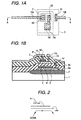
- the semiconductor device includes a first capacitor C PIP of a PIP capacitor formed on a surface of a semiconductor substrate and a second capacitor C FERO of a ferroelectric substance capacitor laminated on the first capacitor C PIP so as to connect thereto in series as shown in Figs. 1A, a plane view, and 1B, a sectional view cut by A-A line.
- the second capacitor C FERO of the ferroelectric substance capacitor is laminated on an element separating insulating film 2 formed on surface of a silicon substrate 1.
- the first capacitor and the second capacitor are connected in series through wiring pattern mutually connected through contact holes h3 to h4.
- the first capacitor is constructed by a first electrode 3 of a polysilicon layer formed on an element separating insulating film 2, a first insulating film 4 formed on the first electrode 3 as two layers of a silicon oxide layer and a silicon nitride layer, and a second electrode 5 of a polysilicon layer further formed on the first insulating film 4.
- the second capacitor is constructed by a first electrode 7 of two-layer film of iridium oxide and iridium formed through a first interlayer insulating film 6a covering the second electrode 5 of the first capacitor C PIP , a ferroelectric substance film 8 of PZT film formed on the first electrode thereof, and a second electrode 9 of two-layer film of iridium and iridium oxide formed on the ferroelectric substance film 8.
- the upper layer thereof is covered with a second interlayer insulating film 6b, mutual connection and taking out of the electrode are performed at wiring patterns 10a to 10c formed on the second interlayer insulating film 6b.
- the lower layer side electrode of the first capacitor that is, the first electrode 3 is connected to the wiring pattern 10b through a first contact hole h1 formed through the first and the second interlayer insulating films 6a and 6b, and is taken out to outside so as to connect a ground wire.
- the upper layer side electrode of the first capacitor that is, the second electrode 5 is connected to the wiring pattern 10c through a contact hole h4 formed through the first and the second interlayer insulating films 6a and 6b, and is formed so as to contact the lower layer side electrode of the second capacitor, that is, the first electrode 7, through the third contact hole h3.
- the upper layer side electrode of the second capacitor that is, the second electrode is connected to the first wiring pattern 10a through the second contact hole h2 so as to connect to signal wire side.
- the element separating insulating film 2 is formed on surface of the silicon substrate 1 by LOCOS method, a desired element region is formed in the element forming region surrounded with the element separating insulating film 2, and a polycrystal silicon film 3 is formed on the element separating insulating film 2 by CVD method.
- a capacitor insulating film 4 of a laminating body of silicon oxide film and silicon nitride film is formed by thermal oxidation and CVD method, then, a polycrystal silicon film 5 is formed by CVD method. After that, patterning is performed by photography method so as to form the first capacitor (Fig. 3A).
- a PSG film is formed for the first interlayer insulating film 6a.
- laminating film of iridium oxide and iridium is formed targeting iridium by spattering method, and a first electrode 7 is formed by patterning the laminating film.
- a PZT film is formed on the first electrode 7 for a ferroelectric substance film 8 by sol-gel method as shown in Fig. 3C.
- Mixed solution of Pb(CH 3 COO) 2 ⁇ 3H 2 O, Zr(t-OC 4 H 9 ) 4 , and Ti(i-OC 3 H 7 ) 4 is used as a starting material.
- the film is dried at 150°C, and temporary baking of 400°C, 30 minutes is performed at dry air atmosphere. After repeating this five times, thermal treatment of more than 700°C is performed.
- the ferroelectric substance film 8 of 250 nm is formed.
- the PZT film is formed placing 0.52 for x (PZT (52/48) hereafter) in PbZr x Ti 1-x O 3 .
- a laminating layer film of iridium oxide layer and iridium layer is formed on the ferroelectric substance film 8 by spattering method (Fig. 3D).
- This laminating layer film of the iridium oxide layer and the iridium layer is formed to be the second electrode 9.
- the second electrode 9 including the iridium oxide layer and the iridium layer is formed to have 200 nm thickness. Accordingly, the structure having ferroelectric substance capacitor as the second capacitor laminated on the first capacitor is obtained.
- a BPSG film is formed as the second interlayer insulating film 6b, and the contact holes h1 to h4 are formed by photolithography as shown in Fig. 3E.
- W tungsten
- Al aluminum
- first to third wiring patterns 10a to 10c are formed pattering by photolithography so as to complete the semiconductor device of the first embodiment of the invention shown in Fig. 1.
- the first and the second capacitors are formed on the element separating insulating film 2, the upper part of the element separating insulating film is used efficiently for the capacitor and it is possible to design large reduction of occupying area. Since the capacitor is formed on the thick element separating film, the element region in the substrate does not receive bad influence so as to provide a high LSI in reliability at michronization even if there is diffusion of Pb or O 2 from the ferroelectric substance thin film.
- ferroelectric substance thin film of the ferroelectric substance capacitor and the electrode of the first capacitor are connected through plugs without contacting directly, diffusion of Pb or O 2 from the ferroelectric substance thin film is cut off well only by forming a barrier layer at the plug so that there is not possibly deterioration caused by diffusion.
- the LSI is possible to form very easily at manufacturing.
- a barrier layer such as titanium, titanium oxide, or titanium nitride may be placed between the polycrystal silicon layer constructing the plug and the first or the second electrode of the second capacitor.
- the titanium layer has action as a junction layer. Adhesion of iridium and silicon, or silicon oxide is not so good. Because of that, the layer comes off partly and there is possibly deterioration of ferroelectric characteristics. However, in the embodiment, titanium oxide layer acts as junction layer. Thus, not only there is diffusion preventing effect to the silicon oxide of Pb or Zr, but also it is possible to improve ferroelectric characteristics even by improvement of adhesion.
- Fig. 4A is a plane view showing the semiconductor device of the second embodiment of the invention
- Fig. 4B is a sectional view cut by B-B line.
- connection of the first capacitor and the second capacitor is performed by the wiring pattern of surface of the substrate through the contact hole formed at each electrode of each capacitor in the first embodiment
- the second electrode 5 positioning at the upper layer side of the first capacitor by plugs constructed by the fourth contact hole h4 formed at the first interlayer insulating film 6a formed on the upper layer of the first capacitor and the first electrode 7 of the second capacitor just on the second electrode 5 are connected after forming the first capacitor. Therefore, since electrodes are connected in the capacitor region, it is possible to design reduction of occupying area comparing the first embodiment.
- Another construction is formed similarly as the first embodiment.
- Forming the fourth contact hole and the plugs do not cause increase of process by performing the same process as forming plugs such as tungsten plug at element region, and it is possible to realize michronization of occupying area.
- Fig. 5A is a plane view showing the semiconductor device of the third embodiment of the invention
- Fig. 5B is a sectional view cut by C-C line.
- the upper portion electrode of the first capacitor and the lower portion electrode of the second capacitor are constructed by a common electrode 11 of two-layer film of iridium and iridium oxide film. It is characterized that the capacitor insulating film 4 for the first capacitor is arranged at lower layer side of the common electrode 11 and the ferroelectric substance film 8 of PZT is arranged on the common electrode 11.
- the upper portion electrode of the first capacitor and the lower part electrode of the second capacitor are used for the common electrode, forming the electrode layer and the interlayer insulating film is needless, so it is possible to provide a semiconductor device very simple and a little difference of surface level.
- Fig. 6 is a view constructing the first capacitor with MOS capacitor.
- a MOSFET as a switching transistor is formed at element region surrounded by the element separating insulating film 2 formed on surface of the silicon substrate.
- Second electrodes 15 of polycrystal silicon film is formed at one of source-drain regions 13a and 13b of the MOSFET through a silicon oxide film 14 so as to form the MOS capacitor.
- a second capacitor is formed through a through hole h4.
- the second capacity constructed by a first electrode 7 of two-layer film of iridium and iridium oxide, a ferroelectric substance film 8 of PZT, and second electrodes 9 of iridium and iridium oxide similarly as the first to the third embodiments.
- the MOSFET is constructed by the above source-drain regions 13a and 13b and a gate electrode of polycrystal silicon formed between the regions through the gate insulating film 16.
- the MOSFET is formed similarly as the ordinal MOS process at manufacturing.
- the first capacitor may be formed so as to extend on the element separating insulating film.
- connection of the first and the second capacitors is changeable similarly as the first to third embodiments.
- the upper layer side electrode of the first capacitor and the lower layer side electrode of the second capacitor are used as a common electrode like the structure of the third embodiment shown in Figs. 5A and 5B, it is desirable to place a barrier layer to prevent diffusion of Pb or O 2 included in the ferroelectric substance film and desirable to use two-layer film of iridium and iridium oxide for the electrode.
- first and the second electrodes of the second capacitor are constructed by the laminating layer film of iridium and iridium oxide in the embodiment, they may be two-layer film of platinum and iridium. In the case using plugs, there is a case that the film may be a single layer film.
- titanium the material withstanding following high temperature process is selectable suitably for the barrier layer or the adhesive layer.
- TaAlN adding aluminum to TaN has characteristic being easy in etching and good in working performance, it is useful material in the case needing patterning.
- TaSiN adding silicon to TaN contains silicon, there are characteristics that preventing effect of diffusion of silicon from silicon oxide layer is high, etching is easy comparing with TaN, and working performance is good. Therefore, it is useful material in the case needing patterning. Further, the TaSiN becomes microcrystal or amorphous by adding Si so that barrier performance improves.
- ferroelectric substance film 8 is used for the ferroelectric substance film 8 in each embodiment, ferroelectric substance such as SBT or high permittivity dielectric such as BST is applicable.
- Material characteristic of iridium is almost equal to the same of platinum. Resistivity of iridium is less than platinum and is desirable material for electrode. Resistivity of iridium oxide is 49x10 -6 ⁇ cm, so there is no problem as material of the electrode.
- iridium permeates through oxygen in the ferroelectric substance film 5 because of crystallization of column shape
- two-layer film of iridium and iridium oxide or two-way film covering the upper layer of iridium with Pt is used in the embodiment. Since the iridium oxide hardly permeates through oxygen because of not having crystal structure of column shape, shortage of oxygen of the ferroelectric substance film can be prevented.
- the iridium oxide layer is conductive and has a fine film structure to prevent permeation of oxygen and like so as to act well as an oxidation preventing film.
- the first capacitor and the second capacitor of the ferroelectric substance capacitor are laminated, reduction of occupying area can be designed without reducing capacity. Since drawing of long wiring is reduced in the semiconductor device, propagation of noise can be reduced and it is possible to design reduction of malfunction.
- the invention provides a semiconductor device having a ferroelectric substance capacitor small in the occupying area and large in capacitance and a semiconductor device having a ferroelectric substance capacitor reducing influence of noise and being few in malfunctions.
- the semiconductor device includes a first capacitor formed on a surface of a semiconductor substrate and a second capacitor of a ferroelectric substance capacitance laminated on the first capacitor so as to connect in series.
Abstract

Description
- The present invention relates to a semiconductor device having a ferroelectric substance capacitor, particularly to a structure for high integration.
- As high integration and michronization of semiconductor device advance, an occupying area of each part is decreased largely in LSI, and research for providing a semiconductor small and high in reliability is repeated.
- In the semiconductor device having the ferroelectric substance capacitor being researched now, a capacitor using an ordinary insulating layer for dielectric substance layer such as a capacitor, called PIP capacitor, having an insulating layer between polysilicon layers, or a capacitor, called MOS capacitor, formed sandwiching a silicon oxide film between a silicon layer and metal is used greatly at the same time in order to detect reverse charge quantity of the ferroelectric substance capacitor and to convert to voltage.
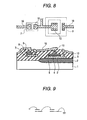
- That is, a ferroelectric substance capacitor CFERO and PIP capacitor CPIP are used greatly in series connection as shown in the equivalent circuit of Fig. 7.
- Conventionally, in order to realize such the semiconductor device, as shown in Figs. 8A and 8B, a first capacitor is formed on an element separating insulating
film 2 formed on surface of asilicon substrate 1 and a second capacitor of a ferroelectric substance capacitor is formed so as to line with the first capacitor on the upper layer of the element region surrounded by the element separatinginsulating film 2. The first capacitor and the second capacitor are connected in series through a wiring pattern connected mutually through contact holes. - Here, the first capacitor is constructed by a
first electrode 3 of a polysilicon layer formed on the element separatinginsulating film 2, a firstinsulating film 4 formed as two layers of a silicon oxide layer and a silicon nitride layer on the upper layer thereof, and asecond electrode 5 of a polysilicon layer formed further the upper layer thereof. - The second capacitor is formed on the upper layer of the element region surrounded by the element separating insulating film as a not-common capacity, and the second capacitor includes a
first electrode 7, aferroelectric substance film 8, and asecond electrode 9. - The mutual connection of the first and second capacitors is achieved through a
wiring pattern 10 connected through contact holes. - Such the capacitor structure has large occupying area and it has been a large problem preventing michronization in LSI.
- Further, there has been a problem that an escape route of noise is few so as to receive easily influence of noise as a device as shown in a explanation view of Fig. 9.
- Thus, the conventional semiconductor device including the ferroelectric substance capacitor has large occupying area and it has been a large problem to prevent high integration of the device.
- Further, the device easily receives influence of noise and it causes malfunction.
- The invention is performed in view of the circumstances, and an object of the invention is to provide a semiconductor device having a ferroelectric substance capacitor small in the occupying area and large in capacitance.
- An another object of the invention is to provide a semiconductor device having a ferroelectric substance capacitor reducing influence of noise and being few in malfunctions.
- The invention is characterized by including a first capacitor formed on surface of a semiconductor substrate and a second capacitor of a ferroelectric substance capacitance laminated on the first capacitor so as to connect in series.
- According to such the construction, it is possible to reduce occupying area without reducing capacitance because the first capacitor and the second capacitor of the ferroelectric substance capacitor are stacked. Since long wiring is reduced in the semiconductor device, propagation of noise is reduced and it is possible to reduce malfunction.
- Preferably, the invention is characterized by that the first capacitor is formed on an element separating insulating film.
- According to such the construction, it is possible to use efficiently on the element separating insulating film because the first and second capacitors are formed on the element separating insulating film. Since the capacitors are formed on the thick element separating insulating film, it is possible to provide high LSI in reliability at michronization without the element region in the substrate does not receive bad reflection even at possible diffusion such as Pb or O2 from the ferroelectric substance thin film.
- Preferably, the invention is characterized by that the upper electrode of the first capacitor and the lower electrode of the second capacitor are connected through plugs formed at an interlayer insulating film.
- According to such the construction, the capacitor is high in reliability because the capacitor of laminating structure is formed using well a process for forming another element region.
- Since the ferroelectric substance thin film of the ferroelectric substance capacitor and the electrode of the first capacitor are connected through plugs without contacting directly, diffusion such as Pb or O2 from the ferroelectric substance thin film is cut off well only forming a barrier layer on the plug.
- Preferably, the invention is characterized by connecting the upper electrode of the first capacitor and the lower electrode of the second capacitor are connected through a wiring layer formed on the upper layer of the second capacitor.
- According to such the construction too, it is possible to obtain a laminating layer capacitor including good series connecting body.
- Preferably, the invention is characterized in that the upper electrode of the first capacitor and the lower electrode of the second capacitor have a common electrode, and that a capacitor insulating film for the first capacitor is arranged at the lower layer side of the common electrode and the ferroelectric substance film is arranged at upper layer side.
- According to such the construction, since the upper electrode of the first capacitor and the lower electrode of the second capacitor have a common electrode, forming of the electrode layer and the interlayer insulating film is needless, and it is possible to provide a semiconductor device very simple and a little in difference of surface level.
- In the case using such the structure, although diffusion such as Pb or O2 from the ferroelectric substance thin film becomes a problem, by using high material in oxygen shielding effect such as two layers structure film of iridium and iridium oxide as the common electrode, diffusion such as Pb or O2 from the ferroelectric substance thin film is depressed well, and it is possible to provide high device in reliability.
- By adopting such the construction, floating capacitance removes and it is possible to design high driving speed.
- Preferably, the invention is characterized in that the lower electrode of the second capacitor includes the laminating film of iridium and iridium oxide.
- According to such the construction, diffusion such as Pb or O2 from the ferroelectric substance thin film is depressed well, and it is possible to provide high device in reliability.
-
- Figs. 1A and 1B are views showing a semiconductor device of a first embodiment of the invention;
- Fig. 2 is a describing view showing propagation of noise of the semiconductor device;
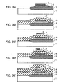
- Figs. 3A to 3E are views showing a process for manufacturing the semiconductor device of a first embodiment of the invention;
- Figs. 4A and 4B are views showing the semiconductor device of the second embodiment of the invention;
- Figs. 5A and 5B are views showing the semiconductor device of the third embodiment of the invention;
- Fig. 6 is a describing view of the principle describing a method of the fourth embodiment of the invention;
- Fig. 7 is a view showing an equivalent circuit of the invention;
- Figs. 8A and 8B are views showing the conventional semiconductor device; and
- Fig. 9 is a describing view showing propagation of noise of the conventional semiconductor device.
-
- A semiconductor device having a PIP capacitor and a ferroelectric substance capacitor will be described for a first embodiment of the invention. The semiconductor device includes a first capacitor CPIP of a PIP capacitor formed on a surface of a semiconductor substrate and a second capacitor CFERO of a ferroelectric substance capacitor laminated on the first capacitor CPIP so as to connect thereto in series as shown in Figs. 1A, a plane view, and 1B, a sectional view cut by A-A line.
- That is, as shown in Figs. 1A and 1B, the second capacitor CFERO of the ferroelectric substance capacitor is laminated on an element separating insulating
film 2 formed on surface of asilicon substrate 1. The first capacitor and the second capacitor are connected in series through wiring pattern mutually connected through contact holes h3 to h4. - Here, the first capacitor is constructed by a
first electrode 3 of a polysilicon layer formed on an element separatinginsulating film 2, a firstinsulating film 4 formed on thefirst electrode 3 as two layers of a silicon oxide layer and a silicon nitride layer, and asecond electrode 5 of a polysilicon layer further formed on the firstinsulating film 4. - The second capacitor is constructed by a
first electrode 7 of two-layer film of iridium oxide and iridium formed through a first interlayerinsulating film 6a covering thesecond electrode 5 of the first capacitor CPIP, aferroelectric substance film 8 of PZT film formed on the first electrode thereof, and asecond electrode 9 of two-layer film of iridium and iridium oxide formed on theferroelectric substance film 8. - Further, the upper layer thereof is covered with a second
interlayer insulating film 6b, mutual connection and taking out of the electrode are performed atwiring patterns 10a to 10c formed on the second interlayerinsulating film 6b. - Here, the lower layer side electrode of the first capacitor, that is, the
first electrode 3 is connected to thewiring pattern 10b through a first contact hole h1 formed through the first and the secondinterlayer insulating films - The upper layer side electrode of the first capacitor, that is, the
second electrode 5 is connected to thewiring pattern 10c through a contact hole h4 formed through the first and the secondinterlayer insulating films first electrode 7, through the third contact hole h3. - Further, the upper layer side electrode of the second capacitor, that is, the second electrode is connected to the
first wiring pattern 10a through the second contact hole h2 so as to connect to signal wire side. - According to such the construction, noise picked up by the first electrode of the first capacitor flows through the ground line efficiently as it is, so it is possible that the capacitor hardly receives influence of the noise because the second electrode of the first capacitor and the first electrode of the second capacitor have the same electric potential as shown in the describing view of Fig. 2.
- Next, a process for manufacturing the ferroelectric substance capacitor will be described with reference to Figs. 3A to 3E.
- First, the element separating insulating
film 2 is formed on surface of thesilicon substrate 1 by LOCOS method, a desired element region is formed in the element forming region surrounded with the element separating insulatingfilm 2, and apolycrystal silicon film 3 is formed on the element separating insulatingfilm 2 by CVD method. On the surface thereof, acapacitor insulating film 4 of a laminating body of silicon oxide film and silicon nitride film is formed by thermal oxidation and CVD method, then, apolycrystal silicon film 5 is formed by CVD method. After that, patterning is performed by photography method so as to form the first capacitor (Fig. 3A). - Continuously, a PSG film is formed for the first
interlayer insulating film 6a. - After that, laminating film of iridium oxide and iridium is formed targeting iridium by spattering method, and a
first electrode 7 is formed by patterning the laminating film. - After that, a PZT film is formed on the
first electrode 7 for aferroelectric substance film 8 by sol-gel method as shown in Fig. 3C. Mixed solution of Pb(CH3COO)2·3H2O, Zr(t-OC4H9)4, and Ti(i-OC3H7)4 is used as a starting material. After spin coating the mixed solution, the film is dried at 150°C, and temporary baking of 400°C, 30 minutes is performed at dry air atmosphere. After repeating this five times, thermal treatment of more than 700°C is performed. Thus, theferroelectric substance film 8 of 250 nm is formed. Here, the PZT film is formed placing 0.52 for x (PZT (52/48) hereafter) in PbZrxTi1-xO3. - Further, a laminating layer film of iridium oxide layer and iridium layer is formed on the
ferroelectric substance film 8 by spattering method (Fig. 3D). This laminating layer film of the iridium oxide layer and the iridium layer is formed to be thesecond electrode 9. Here, thesecond electrode 9 including the iridium oxide layer and the iridium layer is formed to have 200 nm thickness. Accordingly, the structure having ferroelectric substance capacitor as the second capacitor laminated on the first capacitor is obtained. - A BPSG film is formed as the second
interlayer insulating film 6b, and the contact holes h1 to h4 are formed by photolithography as shown in Fig. 3E. - W (tungsten) is filled in the contact holes by CVD method, Al (aluminum) layer is formed on surface of the substrate for wiring pattern, and first to
third wiring patterns 10a to 10c are formed pattering by photolithography so as to complete the semiconductor device of the first embodiment of the invention shown in Fig. 1. - According to such the construction, the first and the second capacitors are formed on the element separating insulating
film 2, the upper part of the element separating insulating film is used efficiently for the capacitor and it is possible to design large reduction of occupying area. Since the capacitor is formed on the thick element separating film, the element region in the substrate does not receive bad influence so as to provide a high LSI in reliability at michronization even if there is diffusion of Pb or O2 from the ferroelectric substance thin film. - Since the ferroelectric substance thin film of the ferroelectric substance capacitor and the electrode of the first capacitor are connected through plugs without contacting directly, diffusion of Pb or O2 from the ferroelectric substance thin film is cut off well only by forming a barrier layer at the plug so that there is not possibly deterioration caused by diffusion.
- The LSI is possible to form very easily at manufacturing.
- Since propagation of noise is reduced, it is possible to provide a semiconductor device a few in malfunctions.
- When there is possibly diffusion of composing element of the ferroelectric substance film, a barrier layer such as titanium, titanium oxide, or titanium nitride may be placed between the polycrystal silicon layer constructing the plug and the first or the second electrode of the second capacitor. Thus, it is possible to obtain a semiconductor device good in working performance and high in reliability.
- Further, the titanium layer has action as a junction layer. Adhesion of iridium and silicon, or silicon oxide is not so good. Because of that, the layer comes off partly and there is possibly deterioration of ferroelectric characteristics. However, in the embodiment, titanium oxide layer acts as junction layer. Thus, not only there is diffusion preventing effect to the silicon oxide of Pb or Zr, but also it is possible to improve ferroelectric characteristics even by improvement of adhesion.
- Next, a second embodiment of the invention will be described with reference to Figs. 4A and 4B. Fig. 4A is a plane view showing the semiconductor device of the second embodiment of the invention, and Fig. 4B is a sectional view cut by B-B line.
- Although connection of the first capacitor and the second capacitor is performed by the wiring pattern of surface of the substrate through the contact hole formed at each electrode of each capacitor in the first embodiment, in the embodiment, the
second electrode 5 positioning at the upper layer side of the first capacitor by plugs constructed by the fourth contact hole h4 formed at the firstinterlayer insulating film 6a formed on the upper layer of the first capacitor and thefirst electrode 7 of the second capacitor just on thesecond electrode 5 are connected after forming the first capacitor. Therefore, since electrodes are connected in the capacitor region, it is possible to design reduction of occupying area comparing the first embodiment. - Another construction is formed similarly as the first embodiment.
- Forming the fourth contact hole and the plugs do not cause increase of process by performing the same process as forming plugs such as tungsten plug at element region, and it is possible to realize michronization of occupying area.
- Next, a third embodiment of the invention will be described with reference to Figs. 5A and 5B. Fig. 5A is a plane view showing the semiconductor device of the third embodiment of the invention, and Fig. 5B is a sectional view cut by C-C line.
- Although connection of the first capacitor and the second capacitor is performed through the contact hole formed at each electrode of each capacitor in the first embodiment, in the embodiment, the upper portion electrode of the first capacitor and the lower portion electrode of the second capacitor are constructed by a
common electrode 11 of two-layer film of iridium and iridium oxide film. It is characterized that thecapacitor insulating film 4 for the first capacitor is arranged at lower layer side of thecommon electrode 11 and theferroelectric substance film 8 of PZT is arranged on thecommon electrode 11. - According to such the construction, since the upper portion electrode of the first capacitor and the lower part electrode of the second capacitor are used for the common electrode, forming the electrode layer and the interlayer insulating film is needless, so it is possible to provide a semiconductor device very simple and a little difference of surface level.
- Although diffusion of Pb and O2 from the ferroelectric substance
thin film 8 becomes problem in the case using such the structure, by using high material in oxygen shielding effect such as two-layer structure film of iridium and iridium oxide as a common electrode, diffusion of Pb and O2 from the ferroelectric substance thin film layer is depressed well, and it is possible to provide a high device in reliability. - Next, a fourth embodiment of the invention will be described.
- Although the embodiment constructed PIP capacitor for the first capacitor in the first to the third embodiments, it is applicable in the case using the MOS capacitor.
- Fig. 6 is a view constructing the first capacitor with MOS capacitor.
- A MOSFET as a switching transistor is formed at element region surrounded by the element separating insulating
film 2 formed on surface of the silicon substrate.Second electrodes 15 of polycrystal silicon film is formed at one of source-drain regions silicon oxide film 14 so as to form the MOS capacitor. At the upper layer thereof, a second capacitor is formed through a through hole h4. - The second capacity constructed by a
first electrode 7 of two-layer film of iridium and iridium oxide, aferroelectric substance film 8 of PZT, andsecond electrodes 9 of iridium and iridium oxide similarly as the first to the third embodiments. - Here, the MOSFET is constructed by the above source-
drain regions gate insulating film 16. - The MOSFET is formed similarly as the ordinal MOS process at manufacturing.
- The first capacitor may be formed so as to extend on the element separating insulating film.
- The connection of the first and the second capacitors is changeable similarly as the first to third embodiments. When the upper layer side electrode of the first capacitor and the lower layer side electrode of the second capacitor are used as a common electrode like the structure of the third embodiment shown in Figs. 5A and 5B, it is desirable to place a barrier layer to prevent diffusion of Pb or O2 included in the ferroelectric substance film and desirable to use two-layer film of iridium and iridium oxide for the electrode.
- Although the first and the second electrodes of the second capacitor are constructed by the laminating layer film of iridium and iridium oxide in the embodiment, they may be two-layer film of platinum and iridium. In the case using plugs, there is a case that the film may be a single layer film.
- Without limiting to titanium, the material withstanding following high temperature process is selectable suitably for the barrier layer or the adhesive layer. The followings too are applicable: titanium, tantalum, zirconium, tungsten, these nitride, and nitride of high melting point metal containing aluminum or silicon such as TaAlN and TaSiN. For example, since TaAlN adding aluminum to TaN has characteristic being easy in etching and good in working performance, it is useful material in the case needing patterning. Since TaSiN adding silicon to TaN contains silicon, there are characteristics that preventing effect of diffusion of silicon from silicon oxide layer is high, etching is easy comparing with TaN, and working performance is good. Therefore, it is useful material in the case needing patterning. Further, the TaSiN becomes microcrystal or amorphous by adding Si so that barrier performance improves.
- Although PZT is used for the
ferroelectric substance film 8 in each embodiment, ferroelectric substance such as SBT or high permittivity dielectric such as BST is applicable. - Material characteristic of iridium is almost equal to the same of platinum. Resistivity of iridium is less than platinum and is desirable material for electrode. Resistivity of iridium oxide is 49x10-6Ωcm, so there is no problem as material of the electrode.
- Although iridium permeates through oxygen in the
ferroelectric substance film 5 because of crystallization of column shape, two-layer film of iridium and iridium oxide or two-way film covering the upper layer of iridium with Pt is used in the embodiment. Since the iridium oxide hardly permeates through oxygen because of not having crystal structure of column shape, shortage of oxygen of the ferroelectric substance film can be prevented. For preventing oxidation of iridium, it is desirable to form a platinum layer on the surface, however it may not be formed. Although there is high possibility that whole of the electrode become iridium oxide layer at oxidation of iridium, the iridium oxide layer is conductive and has a fine film structure to prevent permeation of oxygen and like so as to act well as an oxidation preventing film. - As described above, since the first capacitor and the second capacitor of the ferroelectric substance capacitor are laminated, reduction of occupying area can be designed without reducing capacity. Since drawing of long wiring is reduced in the semiconductor device, propagation of noise can be reduced and it is possible to design reduction of malfunction.
- The invention provides a semiconductor device having a ferroelectric substance capacitor small in the occupying area and large in capacitance and a semiconductor device having a ferroelectric substance capacitor reducing influence of noise and being few in malfunctions. The semiconductor device includes a first capacitor formed on a surface of a semiconductor substrate and a second capacitor of a ferroelectric substance capacitance laminated on the first capacitor so as to connect in series.
Claims (6)
- A semiconductor device comprising:a first capacitor formed on a surface of a semiconductor substrate; anda second capacitor of the ferroelectric substance capacitance laminated on the first capacitor to be serially connected with the first capacitor.
- The semiconductor device as claimed in claim 1, wherein the first capacitor is formed on an element separating insulating film.
- The semiconductor device as claimed in claim 1, wherein an upper electrode of the first capacitor and a lower electrode of the second capacitor are connected through plugs formed in an interlayer insulating film.
- The semiconductor device as claimed in claim 1, wherein an upper electrode of the first capacitor and an lower electrode of the second capacitor are connected through a wiring layer formed above the second capacitor.
- The semiconductor device as claimed in claim 1, further comprising:a common electrode;a capacitor insulating film of the first capacitor provided below the common electrode;a ferroelectric substance film of the second capacitor provided on the common electrode.
- The semiconductor device as claimed in any of claim 1, wherein a lower electrode of the second capacitor includes the laminating film of iridium and iridium oxide.
Applications Claiming Priority (2)
| Application Number | Priority Date | Filing Date | Title |
|---|---|---|---|
| JP2001244102A JP2003060054A (en) | 2001-08-10 | 2001-08-10 | Semiconductor device having ferroelectric capacitor |
| JP2001244102 | 2001-08-10 |
Publications (2)
| Publication Number | Publication Date |
|---|---|
| EP1283545A2 true EP1283545A2 (en) | 2003-02-12 |
| EP1283545A3 EP1283545A3 (en) | 2005-06-22 |
Family
ID=19074090
Family Applications (1)
| Application Number | Title | Priority Date | Filing Date |
|---|---|---|---|
| EP02017850A Ceased EP1283545A3 (en) | 2001-08-10 | 2002-08-08 | Semiconductor device having ferroelectric substance capacitor |
Country Status (3)
| Country | Link |
|---|---|
| US (2) | US6833574B2 (en) |
| EP (1) | EP1283545A3 (en) |
| JP (1) | JP2003060054A (en) |
Cited By (1)
| Publication number | Priority date | Publication date | Assignee | Title |
|---|---|---|---|---|
| WO2005024950A1 (en) * | 2003-09-05 | 2005-03-17 | Fujitsu Limited | Semiconductor device and method for manufacturing same |
Families Citing this family (11)
| Publication number | Priority date | Publication date | Assignee | Title |
|---|---|---|---|---|
| US20040061990A1 (en) * | 2002-09-26 | 2004-04-01 | Dougherty T. Kirk | Temperature-compensated ferroelectric capacitor device, and its fabrication |
| KR100657956B1 (en) * | 2005-04-06 | 2006-12-14 | 삼성전자주식회사 | Multi-bit memory device having resistive material layers as storage node and methods of manufacturing and operating the same |
| JP2010249935A (en) | 2009-04-13 | 2010-11-04 | Sony Corp | Display device |
| JP2011228462A (en) * | 2010-04-19 | 2011-11-10 | Taiyo Yuden Co Ltd | Thin film capacitor |
| US10128327B2 (en) | 2014-04-30 | 2018-11-13 | Stmicroelectronics, Inc. | DRAM interconnect structure having ferroelectric capacitors exhibiting negative capacitance |
| US10361213B2 (en) | 2016-06-28 | 2019-07-23 | Sandisk Technologies Llc | Three dimensional memory device containing multilayer wordline barrier films and method of making thereof |
| US10355139B2 (en) | 2016-06-28 | 2019-07-16 | Sandisk Technologies Llc | Three-dimensional memory device with amorphous barrier layer and method of making thereof |
| US10115735B2 (en) | 2017-02-24 | 2018-10-30 | Sandisk Technologies Llc | Semiconductor device containing multilayer titanium nitride diffusion barrier and method of making thereof |
| US10229931B1 (en) | 2017-12-05 | 2019-03-12 | Sandisk Technologies Llc | Three-dimensional memory device containing fluorine-free tungsten—word lines and methods of manufacturing the same |
| US10615123B2 (en) | 2018-03-14 | 2020-04-07 | Sandisk Technologies Llc | Three-dimensional memory device containing compositionally graded word line diffusion barrier layer for and methods of forming the same |
| CN109671722B (en) * | 2018-12-13 | 2021-02-26 | 武汉华星光电半导体显示技术有限公司 | Organic light emitting diode array substrate and manufacturing method thereof |
Citations (5)
| Publication number | Priority date | Publication date | Assignee | Title |
|---|---|---|---|---|
| US5506748A (en) | 1991-09-20 | 1996-04-09 | Rohm Co., Ltd. | Capacitor for semiconductor integrated circuit |
| WO1998000871A1 (en) | 1996-06-27 | 1998-01-08 | Gennum Corporation | Multi-layer film capacitor structures and method |
| US5989927A (en) | 1996-05-30 | 1999-11-23 | Oki Electric Industry Co., Ltd. | Non-volatile semiconductor and memory cell and method for production thereof |
| US6115233A (en) | 1996-06-28 | 2000-09-05 | Lsi Logic Corporation | Integrated circuit device having a capacitor with the dielectric peripheral region being greater than the dielectric central region |
| US6194753B1 (en) | 1995-12-27 | 2001-02-27 | Hyundai Electronics Industries Co., Ltd. | Method of forming a perovskite structure semiconductor capacitor |
Family Cites Families (13)
| Publication number | Priority date | Publication date | Assignee | Title |
|---|---|---|---|---|
| JP3021614B2 (en) * | 1990-11-06 | 2000-03-15 | オリンパス光学工業株式会社 | Memory element |
| JP3299837B2 (en) * | 1993-07-22 | 2002-07-08 | シャープ株式会社 | Semiconductor storage device |
| JP3131340B2 (en) * | 1993-12-28 | 2001-01-31 | シャープ株式会社 | Ferroelectric memory element |
| JP3368726B2 (en) * | 1995-08-07 | 2003-01-20 | ヤマハ株式会社 | Semiconductor memory device and manufacturing method thereof |
| US6198617B1 (en) * | 1999-01-12 | 2001-03-06 | United Microelectronics Corp. | Multi-layer metal capacitor |
| US6140672A (en) * | 1999-03-05 | 2000-10-31 | Symetrix Corporation | Ferroelectric field effect transistor having a gate electrode being electrically connected to the bottom electrode of a ferroelectric capacitor |
| JP4322347B2 (en) * | 1999-03-15 | 2009-08-26 | エルピーダメモリ株式会社 | Semiconductor device and manufacturing method thereof |
| JP2000349251A (en) * | 1999-06-09 | 2000-12-15 | Nissan Motor Co Ltd | Semiconductor device |
| JP2001060670A (en) * | 1999-06-16 | 2001-03-06 | Matsushita Electronics Industry Corp | Semiconductor device and manufacture thereof |
| JP2001237395A (en) * | 2000-02-22 | 2001-08-31 | Matsushita Electric Ind Co Ltd | Semiconductor memory device |
| KR20020004539A (en) * | 2000-07-06 | 2002-01-16 | 박종섭 | Method for forming FeRAM capable of preventing hydrogen diffusion |
| US6720596B2 (en) * | 2000-10-17 | 2004-04-13 | Matsushita Electric Industrial Co., Ltd. | Semiconductor device and method for driving the same |
| US6646323B2 (en) * | 2001-05-04 | 2003-11-11 | Texas Instruments Incorporated | Zero mask high density metal/insulator/metal capacitor |
-
2001
- 2001-08-10 JP JP2001244102A patent/JP2003060054A/en active Pending
-
2002
- 2002-08-08 EP EP02017850A patent/EP1283545A3/en not_active Ceased
- 2002-08-09 US US10/216,109 patent/US6833574B2/en not_active Expired - Lifetime
-
2004
- 2004-11-12 US US10/988,051 patent/US7531862B2/en not_active Expired - Fee Related
Patent Citations (5)
| Publication number | Priority date | Publication date | Assignee | Title |
|---|---|---|---|---|
| US5506748A (en) | 1991-09-20 | 1996-04-09 | Rohm Co., Ltd. | Capacitor for semiconductor integrated circuit |
| US6194753B1 (en) | 1995-12-27 | 2001-02-27 | Hyundai Electronics Industries Co., Ltd. | Method of forming a perovskite structure semiconductor capacitor |
| US5989927A (en) | 1996-05-30 | 1999-11-23 | Oki Electric Industry Co., Ltd. | Non-volatile semiconductor and memory cell and method for production thereof |
| WO1998000871A1 (en) | 1996-06-27 | 1998-01-08 | Gennum Corporation | Multi-layer film capacitor structures and method |
| US6115233A (en) | 1996-06-28 | 2000-09-05 | Lsi Logic Corporation | Integrated circuit device having a capacitor with the dielectric peripheral region being greater than the dielectric central region |
Cited By (2)
| Publication number | Priority date | Publication date | Assignee | Title |
|---|---|---|---|---|
| WO2005024950A1 (en) * | 2003-09-05 | 2005-03-17 | Fujitsu Limited | Semiconductor device and method for manufacturing same |
| US7498625B2 (en) | 2003-09-05 | 2009-03-03 | Fujitsu Microelectronics Limited | Semiconductor device and manufacturing method thereof |
Also Published As
| Publication number | Publication date |
|---|---|
| US6833574B2 (en) | 2004-12-21 |
| US7531862B2 (en) | 2009-05-12 |
| US20030107072A1 (en) | 2003-06-12 |
| EP1283545A3 (en) | 2005-06-22 |
| US20050087840A1 (en) | 2005-04-28 |
| JP2003060054A (en) | 2003-02-28 |
Similar Documents
| Publication | Publication Date | Title |
|---|---|---|
| US6737694B2 (en) | Ferroelectric memory device and method of forming the same | |
| US6235573B1 (en) | Methods of forming ferroelectric random access memory devices having shared capacitor electrodes | |
| US7888231B2 (en) | Method for fabricating a three-dimensional capacitor | |
| US6399974B1 (en) | Semiconductor memory device using an insulator film for the capacitor of the memory cell and method for manufacturing the same | |
| US6239462B1 (en) | Semiconductor capacitive device having improved anti-diffusion properties and a method of making the same | |
| US7531862B2 (en) | Semiconductor device having ferroelectric substance capacitor | |
| JP3269528B2 (en) | Semiconductor device having capacitive element and method of manufacturing the same | |
| EP0917204B1 (en) | Interconnection between MOS transistor and capacitor | |
| US7615814B2 (en) | Ferroelectric device having a contact for taking the potential of a metal film and a plurality of capacitors positioned periodically | |
| KR20060135494A (en) | Semiconductor device and method for fabricating the same | |
| JP2003086771A (en) | Capacitive element, and semiconductor device and its manufacturing method | |
| CN111276509B (en) | Integrated circuit including variable resistance type memory unit and resistance unit and forming method | |
| KR100326253B1 (en) | Method for forming capacitor in semiconductor device | |
| JP2000323685A (en) | Manufacture of semiconductor device and memory cell | |
| JPH09275193A (en) | Semiconductor storage device | |
| JPH10209394A (en) | Semiconductor storage device and its manufacture | |
| KR100587662B1 (en) | Capacitor of semicon ductor device and method for fabricating the same | |
| US20040227171A1 (en) | Semiconductor memory device and its manufacturing method | |
| EP0978881A2 (en) | Ferroelectric capacitor and its manufacturing method | |
| JP3595397B2 (en) | Method for manufacturing semiconductor device | |
| US20030057464A1 (en) | Ferroelectric memory device and method of fabricating the same | |
| JPH11103029A (en) | Capacitor, semiconductor memory device therewith, and manufacture thereof | |
| JP3820952B2 (en) | Semiconductor device and manufacturing method thereof | |
| JPH11145418A (en) | Dielectric memory | |
| JP2004289004A (en) | Semiconductor device and its manufacturing method |
Legal Events
| Date | Code | Title | Description |
|---|---|---|---|
| PUAI | Public reference made under article 153(3) epc to a published international application that has entered the european phase |
Free format text: ORIGINAL CODE: 0009012 |
|
| AK | Designated contracting states |
Designated state(s): AT BE BG CH CY CZ DE DK EE ES FI FR GB GR IE IT LI LU MC NL PT SE SK TR |
|
| AX | Request for extension of the european patent |
Extension state: AL LT LV MK RO SI |
|
| PUAL | Search report despatched |
Free format text: ORIGINAL CODE: 0009013 |
|
| AK | Designated contracting states |
Kind code of ref document: A3 Designated state(s): AT BE BG CH CY CZ DE DK EE ES FI FR GB GR IE IT LI LU MC NL PT SE SK TR |
|
| AX | Request for extension of the european patent |
Extension state: AL LT LV MK RO SI |
|
| RIC1 | Information provided on ipc code assigned before grant |
Ipc: 7H 01L 27/06 B Ipc: 7H 01L 27/08 B Ipc: 7H 01L 21/02 A |
|
| 17P | Request for examination filed |
Effective date: 20051025 |
|
| AKX | Designation fees paid |
Designated state(s): DE FR IT NL |
|
| 17Q | First examination report despatched |
Effective date: 20060418 |
|
| 17Q | First examination report despatched |
Effective date: 20060418 |
|
| STAA | Information on the status of an ep patent application or granted ep patent |
Free format text: STATUS: THE APPLICATION HAS BEEN REFUSED |
|
| 18R | Application refused |
Effective date: 20090923 |