EP1283503A2 - Access control system and method - Google Patents
Access control system and method Download PDFInfo
- Publication number
- EP1283503A2 EP1283503A2 EP02255481A EP02255481A EP1283503A2 EP 1283503 A2 EP1283503 A2 EP 1283503A2 EP 02255481 A EP02255481 A EP 02255481A EP 02255481 A EP02255481 A EP 02255481A EP 1283503 A2 EP1283503 A2 EP 1283503A2
- Authority
- EP
- European Patent Office
- Prior art keywords
- signal
- vehicle
- receiving means
- closures
- authorisation device
- Prior art date
- Legal status (The legal status is an assumption and is not a legal conclusion. Google has not performed a legal analysis and makes no representation as to the accuracy of the status listed.)
- Ceased
Links
Images


Classifications
-
- G—PHYSICS
- G07—CHECKING-DEVICES
- G07C—TIME OR ATTENDANCE REGISTERS; REGISTERING OR INDICATING THE WORKING OF MACHINES; GENERATING RANDOM NUMBERS; VOTING OR LOTTERY APPARATUS; ARRANGEMENTS, SYSTEMS OR APPARATUS FOR CHECKING NOT PROVIDED FOR ELSEWHERE
- G07C9/00—Individual registration on entry or exit
- G07C9/00174—Electronically operated locks; Circuits therefor; Nonmechanical keys therefor, e.g. passive or active electrical keys or other data carriers without mechanical keys
- G07C9/00309—Electronically operated locks; Circuits therefor; Nonmechanical keys therefor, e.g. passive or active electrical keys or other data carriers without mechanical keys operated with bidirectional data transmission between data carrier and locks
-
- G—PHYSICS
- G07—CHECKING-DEVICES
- G07C—TIME OR ATTENDANCE REGISTERS; REGISTERING OR INDICATING THE WORKING OF MACHINES; GENERATING RANDOM NUMBERS; VOTING OR LOTTERY APPARATUS; ARRANGEMENTS, SYSTEMS OR APPARATUS FOR CHECKING NOT PROVIDED FOR ELSEWHERE
- G07C9/00—Individual registration on entry or exit
- G07C9/00174—Electronically operated locks; Circuits therefor; Nonmechanical keys therefor, e.g. passive or active electrical keys or other data carriers without mechanical keys
- G07C9/00182—Electronically operated locks; Circuits therefor; Nonmechanical keys therefor, e.g. passive or active electrical keys or other data carriers without mechanical keys operated with unidirectional data transmission between data carrier and locks
- G07C2009/00261—Electronically operated locks; Circuits therefor; Nonmechanical keys therefor, e.g. passive or active electrical keys or other data carriers without mechanical keys operated with unidirectional data transmission between data carrier and locks the keyless data carrier having more than one function
- G07C2009/00277—Electronically operated locks; Circuits therefor; Nonmechanical keys therefor, e.g. passive or active electrical keys or other data carriers without mechanical keys operated with unidirectional data transmission between data carrier and locks the keyless data carrier having more than one function opening of different locks separately
-
- G—PHYSICS
- G07—CHECKING-DEVICES
- G07C—TIME OR ATTENDANCE REGISTERS; REGISTERING OR INDICATING THE WORKING OF MACHINES; GENERATING RANDOM NUMBERS; VOTING OR LOTTERY APPARATUS; ARRANGEMENTS, SYSTEMS OR APPARATUS FOR CHECKING NOT PROVIDED FOR ELSEWHERE
- G07C9/00—Individual registration on entry or exit
- G07C9/00174—Electronically operated locks; Circuits therefor; Nonmechanical keys therefor, e.g. passive or active electrical keys or other data carriers without mechanical keys
- G07C9/00309—Electronically operated locks; Circuits therefor; Nonmechanical keys therefor, e.g. passive or active electrical keys or other data carriers without mechanical keys operated with bidirectional data transmission between data carrier and locks
- G07C2009/00507—Electronically operated locks; Circuits therefor; Nonmechanical keys therefor, e.g. passive or active electrical keys or other data carriers without mechanical keys operated with bidirectional data transmission between data carrier and locks keyless data carrier having more than one function
- G07C2009/00523—Electronically operated locks; Circuits therefor; Nonmechanical keys therefor, e.g. passive or active electrical keys or other data carriers without mechanical keys operated with bidirectional data transmission between data carrier and locks keyless data carrier having more than one function opening of different locks separately
-
- G—PHYSICS
- G07—CHECKING-DEVICES
- G07C—TIME OR ATTENDANCE REGISTERS; REGISTERING OR INDICATING THE WORKING OF MACHINES; GENERATING RANDOM NUMBERS; VOTING OR LOTTERY APPARATUS; ARRANGEMENTS, SYSTEMS OR APPARATUS FOR CHECKING NOT PROVIDED FOR ELSEWHERE
- G07C2209/00—Indexing scheme relating to groups G07C9/00 - G07C9/38
- G07C2209/60—Indexing scheme relating to groups G07C9/00174 - G07C9/00944
- G07C2209/63—Comprising locating means for detecting the position of the data carrier, i.e. within the vehicle or within a certain distance from the vehicle
Definitions
- the present invention relates to an access control system and an access control method. More particularly, the present invention relates to an access control system and an access control method that determines an appropriate closure or closures of an associated vehicle to be unlocked and or unlatched depending upon the direction of approach of a vehicle user and inputs from the vehicle user.
- RKE active remote keyless entry
- passive remote keyless entry devices comprising a transponder carried by a vehicle user that may be interrogated by a transceiver associated with a vehicle in order to unlatch the vehicle closures are also known.
- the present invention seeks to overcome, or at least mitigate the aforesaid problem.
- One aspect of the present invention provides an access control system for a vehicle having at least two closures, the system comprising a receiving means, the receiving means being so constructed and arranged as to determine the angular position of an associated authorisation device relative to the receiving means thereby enabling the system to determine the appropriate vehicle closure(s) to unlock and/or unlatch, the system being capable of determining additional closures to be unlocked and/or unlatched in accordance with predetermined criteria in response to the period of time for which an input signal is received by the system from the authorisation device.
- a second aspect of the present invention provides A method of unlocking and/or unlatching a selected one or more closures of a vehicle having at least two said closures, the method comprising the steps of: i) providing an access control system comprising receiving means capable of determining the angular position of an associated authorisation device relative to the receiving means; ii) the receiving means receiving a signal from the authorisation device; iii) the system determining the angle from which the signal was received and the duration of the signal; iv) the system signalling the unlocking and/or unlatching of one or more of the closures in response to the determined angle and signal duration in accordance with predetermined criteria.
- a third aspect of the present invention provides an access control system for a vehicle having at least two closures, the system comprising receiving means, the receiving means being so construed and arranged as to determine the angular position of an associated authorisation device, relative to the receiving means thereby enabling the system to determine the appropriate vehicle closure(s) to unlock and/or unlatch, the system being capable of distinguishing between two levels of authorisation, such that the system is programmed not to signal the locking and/or unlatching of one or more closures irrespective of the relative position of an authorisation device having a first level of authorisation, but does not permit the unlocking or unlatching of the one or more closures in response to an authorisation device having a second level of authorisation.
- transceiver 44 a combined external transmitting and receiving means (hereinafter referred to as transceiver 44).
- the transceiver 44 comprises a transmitter 115 and a receiver 112 mounted at the narrow end of a mouth 114.
- the transmitter 115 transmits and the receiver 112 detects signals of a suitable form of electromagnetic radiation or sound waves.
- radio frequency (RF) waves such as microwaves are transmitted and detected.
- the angle over which the signal is transmitted and detected is limited by the angle between the sides of the mouth 114. It can be seen that in Figure 2, the angle is approximately 90°, although it may be varied according to particular user requirements.
- the transmitter 115, receiver 112 and mouth 114 are fixedly mounted on a rotatable shaft 118 by a bracket 116, the shaft 118 being an output shaft of a motor (not shown) such as a suitable electric motor arranged to enable the transmitter, receiver and dish to rotate in a direction X about an axis substantially perpendicular to the axis in which transmitter is directed.
- a rotary encoder 120 is provided to determine the relative rotary position of the receiver 112.
- FIG. 2 and 5 a five door estate (station wagon) type vehicle 12 is illustrated having four side doors 14a, 14b, 14c, 14d to access the passenger compartment 22 and rear tailgate 18 to access the storage compartment 129.
- Door latches 16a, 16b, 16c, 16d, having power locking mechanisms are associated with each door.
- a further latch 20 with a power locking mechanism is associated with the storage rear tailgate 18.
- the transceiver means 44 is mounted on the vehicle 12 in a position where a substantially unobstructed 360° signal transmission and reception may occur. In this embodiment the transceiver 44 is mounted to the underside of the roof of the passenger compartment 22 of the vehicle.
- a controller 24 controls the overall function of the system and has associated therewith memory 124.
- a manual override 30 and input means 56 (which may in practice be the same component) provide a further input to the controller 24.
- the controller 24 signals the motor to cause the transceiver 44 to rotate continuously through a full 360° arc whilst simultaneously signalling the transmitter 115 to transmit an interrogation signal so as to locate any authorisation device (AD 26) in range.
- the AD 26 is in the form of a transponder card or the like normally carried by an authorised vehicle user 132.
- the interrogation signal causes AD 26 to power-up and transmit a corresponding coded response signal to the receiver 112. Because the signal is sent using electromagnetic radiation, the response signal is sent almost instantaneously and there is therefore no danger of the receiver having rotated out of range of the response signal when it is sent.
- the rate of rotation of the transceiver 44 is advantageously sufficiently high to ensure that approaching authorised users are detected before reaching the vehicle.
- the controller 24 When a signal is detected by the receiver 112 it is transmitted to the controller 24 for authentication. If it is determined that the AD 26 is authorised for the particular vehicle 12 in question, the controller 24 queries the position encoder 120 of the transceiver 44 as to the angle ⁇ of the transceiver 44 at the point at which a signal from the AD 26 was received by the receiver 112. The controller 24 then compares this angle ⁇ to values stored within the memory 58 associated with the controller. For a given range of angles, the memory stores a predetermined instruction as to which of the vehicle latches 16a, 16b, 16c, 16d, 20 should be unlocked.
- the controller 24 processes this instruction and signals the door lock actuator (not shown) of an appropriate one or more of the right front, right rear, left front and left rear door latches 16a, 16b, 16c, 16d for doors 14a, 14b, 14c and 14d to unlock respectively as well as storage compartment closure lock actuator (not shown) for the tailgate 18.
- the controller 24 determines from its associated memory 58 that the authorised user 132 is at the right hand side of the vehicle and will thus signal the door lock actuators to unlock the right front and right rear door latches 16. If, however, the AD 26 is detected at an angle ⁇ of approximately 180°, the controller 24 will signal the actuator to unlock the storage compartment latch 20 and if an angle ⁇ of 270° is detected, the controller will signal the unlocking of the left front and left rear door lock actuators to unlock latches 16.
- the access control system 10 signals the unlocking of vehicle doors on both sides of the vehicle.
- two levels of authorisation may exist, one for an authorised vehicle driver, and a second for authorised vehicle passengers.
- the controller 24 distinguishes between the authorisation levels and only unlocks the driver's door latch 16 if a person carrying an AD 26 having a driver's level of authorisation approaches this side of the vehicle. If a person 132 carrying an AD 26 enters the vehicle, and wishes to permit entry to other users not carrying ADs, a manual override is provided in an accessible location to cause additional, although not necessarily all of the vehicle closures 14a, 14b, 14c, 14d, 18 to be unlocked. The manual override 30 may also enable the doors to be locked when the vehicle 12 is occupied.
- a delay timer (not shown) coupled to a latch position sensor (not shown) may be built into the access control system 10 to cause the controller 24 to signal locking once a certain time has elapsed after the vehicle 12 has been exited. Alternatively, locking occurs once the AD 26 has left the range of the transceiver 44.
- rotation of the transceiver 44 may be suspended or the rate of rotation reduced to reduce the power consumption thereof and thereby minimise the risk of a flat battery upon the user's return to the vehicle.
- the transmitter power may also be reduced to minimise power consumption.
- rotation is suspended, it is preferable for the transceiver 44 to be directed towards the driver's door 14a during suspension as it is most likely that the authorised user 132 will approach this door first. Once a user is detected, the rotation recommences.
- the motion sensor (not shown) be integrated into the system so that the transceiver 44 may be powered down whilst the vehicle is moving.
- system 10 is programmable by the authorised user or by workshop personnel to change the range of angles over which certain closures are unlocked, as well as the particular closures to be unlocked over each angle so that the system may be tailored to user requirements.
- system of this embodiment employs input means 56.
- a transceiver 44 having a relatively narrow angle of signal transmission may require a reduced power consumption, or have a longer range for the same power consumption in comparison with known passive entry transmitting devices.
- This embodiment differs from the first embodiment in that no transmitter 115 is provided as part of the access control system 210, and in that the receiver 244 is stationary and comprises in this embodiment four separate receivers designated 212a, 212b, 212c and 212d.
- the horizontal angle over which each receiver is capable of detecting a signal is restricted by vertical dividers 214a, 214b, 214c and 214d.
- the receiver 244 is shown located in a similar position to the transceiver 44 of the first embodiment and as such effectively divides the area surrounding the vehicle into four sectors 260, 262, 264 and 266 which substantially correspond to the right side, rear, left side and front of the vehicle respectively.
- receiver 212d is omitted since no closure suitable for unlocking using the system is provided at the front of the vehicle 212.
- the second embodiment is intended for use with an "active" remote keyless entry (RKE) ADs (commonly known as a "plip") or passive entry systems in which the AD transmits periodic signal without being interrogated by a transceiver.
- RKE ADs 226 generally comprise an infra-red, radiofrequency or ultrasonic transmitter and have their own power source such as a battery. Because the user themselves actively sends an unlocking signal to the receiver 244 or the AD 226 sends a periodic signal, it is unnecessary to provide a corresponding transmitter on the vehicle 12 to actively search for and interrogate the AD as in the previous embodiment.
- the controller 224 of the access control system 210 determines the appropriate closure(s) to unlock and sends unlock signals to the corresponding lock actuator(s) of latches 216a, 216b, 216c, 216d, 220 in a similar manner to the controller 224 of the first embodiment.
- the manual override 230 may be used to lock/unlock the remaining closures.
- a user wishes to lock the vehicle, he/she actuates the identification means a second time to trigger the locking of all of the latches 216, 218 if an "active" AD is used. If a periodic signalling AD 226 is used, locking is triggered once the transceiver fails to receive a signal from the AD for a predetermined period of time.
- the access control system of the this embodiment could be used with a non-powered AD 26 similar to that disclosed in the previous embodiment.
- the transmitter may be provided in the middle of receivers 212a, 212b, 212c and 212d.
- the direction sensing described above operates in conjunction with means to time the period for which an active AD 226 is actuated to ensure the correct doors are unlocked.
- FIG. 7 operation of the access control system 210 is illustrated as a flow chart.
- a vehicle user actuates their AD 226 and a signal is transmitted by one of the receivers 212a, 212b, 212c, 212d to controller 224.
- the controller 224 sets the look-up value for the latch x to 0 and starts a timer that is associated with the controller 224.
- the look-up values stored by memory 224 are summarised by Table 1 below.
- Lock x Time y Latch 0 Driver 14a side or front passenger door 14d closest to authorisation device 226.
- the controller 224 signals the door latch 16a to unlock (in a RHD vehicle) immediately thereafter, having determined the direction of approach due to the signal from the AD 226 having been detected by receiver 212b.
- the controller 224 then waits a time y which for latch 0 equates to 1 second. If, after this time y , the AD 226 is no longer actuated, the controller 224 ends the unlocking procedure. If, however, the AD 226 is still actuated, the controller 224 then checks whether the look-up value for latch x is at its maximum value (ie all of the latches have been unlocked).
- the controller 224 ends the unlocking procedure. However, if the maximum has not been reached, the controller then refers to the next latch x in the table, which in this case is the latch corresponding to the passenger door 214b behind the driver's door 214a, and signals the left front door lock actuator to unlock the latch 216b, and then waits a time y which for lock 1 again equates to 1 second. This procedure is then repeated until either the user has decided that sufficient latches have been unlocked and he/she can thus cease actuating the AD 226, or all of the latches have been unlocked and the procedure also therefore ends. An audible or visible indication (not shown) of the latches that are unlocked may be provided.
- vehicle users may override the current locked state of any of the closures by actuating the manual override 230.
- This may be in the form of a conventional sill button in relation to the vehicle side doors 14a, 14b, 14c, 14d or may be one or more electrical switches actuable by the vehicle user.
- the transmitter and receiver may be physically separated from one another.
- the receivers of the second embodiment may also be mutually separated so as to have, for example, receivers proximate the front, rear and side windows.
- the system of the first embodiment could be used to track the vector of a person walking towards a vehicle and from this determine the appropriate door to be unlocked.
- the system may also unlatch the closures by being connected to corresponding power latch mechanisms. This would be particularly advantageous in the case of a rear boot/trunk lid as they are often not provided with an external latch release means.
- the system may enable closures to be unlocked sequentially.
- a user may first walk to the boot, causing the boot lid to be unlocked, and the subsequentially walk to the driver's door causing this to then be unlocked.
- the controller may also output to actuators and the like for adjusting the seating, steering wheel and mirror positions, for example, in order to personalise the vehicle settings for a particular user carrying a response device.
- the system may be retrofittable to vehicles or may be fitted at the time of vehicle manufacture.
- the system may be adapted for vehicles having fewer or more closures than shown in the Figures.
- Access to the vehicle may be provided by a user supplying biometric data to the vehicle such a fingerprint or a voice input, in which case the term "authorisation device” should be construed to include such data.
Abstract
Description
- The present invention relates to an access control system and an access control method. More particularly, the present invention relates to an access control system and an access control method that determines an appropriate closure or closures of an associated vehicle to be unlocked and or unlatched depending upon the direction of approach of a vehicle user and inputs from the vehicle user.
- The use of active remote keyless entry (RKE) devices such as ultrasonic or infra-red type transmitters carried by a vehicle user and which remotely signal the unlocking of vehicle closures (eg side doors, rear tailgate, hatchback, boot/trunk lid) once actuated by the user is known. Similarly, passive remote keyless entry devices comprising a transponder carried by a vehicle user that may be interrogated by a transceiver associated with a vehicle in order to unlatch the vehicle closures are also known.
- However, when either system is used, once the access control system associated with the vehicle has determined that access is to be permitted, it is usual that all closures are unlocked.
- When a vehicle user approaches a vehicle it is usual for him/her to proceed directly towards the closure at which they wish to enter the passenger compartment or storage area of the vehicle, without first carrying out a visual inspection around the perimeter of the vehicle. This behaviour enables an unauthorised person such as a potential hijacker to hide behind the vehicle in a blind spot and subsequently gain unauthorised access to the vehicle once all of the closures are unlocked. Clearly, such a situation is undesirable.
- The present invention seeks to overcome, or at least mitigate the aforesaid problem.
- One aspect of the present invention provides an access control system for a vehicle having at least two closures, the system comprising a receiving means, the receiving means being so constructed and arranged as to determine the angular position of an associated authorisation device relative to the receiving means thereby enabling the system to determine the appropriate vehicle closure(s) to unlock and/or unlatch, the system being capable of determining additional closures to be unlocked and/or unlatched in accordance with predetermined criteria in response to the period of time for which an input signal is received by the system from the authorisation device.
- A second aspect of the present invention provides A method of unlocking and/or unlatching a selected one or more closures of a vehicle having at least two said closures, the method comprising the steps of: i) providing an access control system comprising receiving means capable of determining the angular position of an associated authorisation device relative to the receiving means; ii) the receiving means receiving a signal from the authorisation device; iii) the system determining the angle from which the signal was received and the duration of the signal; iv) the system signalling the unlocking and/or unlatching of one or more of the closures in response to the determined angle and signal duration in accordance with predetermined criteria.
- A third aspect of the present invention provides an access control system for a vehicle having at least two closures, the system comprising receiving means, the receiving means being so construed and arranged as to determine the angular position of an associated authorisation device, relative to the receiving means thereby enabling the system to determine the appropriate vehicle closure(s) to unlock and/or unlatch, the system being capable of distinguishing between two levels of authorisation, such that the system is programmed not to signal the locking and/or unlatching of one or more closures irrespective of the relative position of an authorisation device having a first level of authorisation, but does not permit the unlocking or unlatching of the one or more closures in response to an authorisation device having a second level of authorisation.
- Embodiments of the present invention will now be described, by way of example only, with reference to the accompanying drawings in which:
- FIGURE 1 is a view of a transmitting and receiving means of an access control system according to one embodiment of the present invention;
- FIGURE 2 is a plan view of a vehicle illustrating the access control system in use;
- FIGURE 3 is a receiving means for use in an access control system according to a second embodiment of the present invention;
- FIGURE 4 is a plan view of a vehicle illustrating the access control system of the second embodiment of the present invention in use;
- FIGURE 5 is a schematic block diagram illustrating the access control system of the first embodiment fitted in a vehicle;
- FIGURE 6 is a schematic block diagram illustrating the access control system according to a second embodiment of the invention; and
- FIGURE 7 is a flow chart illustrating the operation of the system.
-
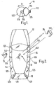
- Referring to Figure 1, there is shown a combined external transmitting and receiving means (hereinafter referred to as transceiver 44). The
transceiver 44 comprises atransmitter 115 and areceiver 112 mounted at the narrow end of amouth 114. Thetransmitter 115 transmits and thereceiver 112 detects signals of a suitable form of electromagnetic radiation or sound waves. In a preferred embodiment, radio frequency (RF) waves such as microwaves are transmitted and detected. The angle over which the signal is transmitted and detected is limited by the angle between the sides of themouth 114. It can be seen that in Figure 2, the angle is approximately 90°, although it may be varied according to particular user requirements. - The
transmitter 115,receiver 112 andmouth 114 are fixedly mounted on arotatable shaft 118 by abracket 116, theshaft 118 being an output shaft of a motor (not shown) such as a suitable electric motor arranged to enable the transmitter, receiver and dish to rotate in a direction X about an axis substantially perpendicular to the axis in which transmitter is directed. Arotary encoder 120 is provided to determine the relative rotary position of thereceiver 112. - Turning now to Figures 2 and 5, a five door estate (station wagon)
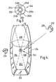
type vehicle 12 is illustrated having four side doors 14a, 14b, 14c, 14d to access thepassenger compartment 22 andrear tailgate 18 to access thestorage compartment 129.Door latches further latch 20 with a power locking mechanism is associated with the storagerear tailgate 18. However, the present invention may be usefully provided in any vehicle having at least two closures. The transceiver means 44 is mounted on thevehicle 12 in a position where a substantially unobstructed 360° signal transmission and reception may occur. In this embodiment thetransceiver 44 is mounted to the underside of the roof of thepassenger compartment 22 of the vehicle. In this position, transmission and reception is only hindered by the relativelynarrow door pillars 125 of the vehicle. Acontroller 24 controls the overall function of the system and has associated therewithmemory 124. Amanual override 30 and input means 56 (which may in practice be the same component) provide a further input to thecontroller 24. - Under normal operating conditions when power is supplied to the system from, a vehicle battery (not shown), for example, the
controller 24 signals the motor to cause thetransceiver 44 to rotate continuously through a full 360° arc whilst simultaneously signalling thetransmitter 115 to transmit an interrogation signal so as to locate any authorisation device (AD 26) in range. In this embodiment theAD 26 is in the form of a transponder card or the like normally carried by anauthorised vehicle user 132. - If a compatible
authorisation device AD 26 is located within the range of thetransmitter 115 the interrogation signal causesAD 26 to power-up and transmit a corresponding coded response signal to thereceiver 112. Because the signal is sent using electromagnetic radiation, the response signal is sent almost instantaneously and there is therefore no danger of the receiver having rotated out of range of the response signal when it is sent. The rate of rotation of thetransceiver 44 is advantageously sufficiently high to ensure that approaching authorised users are detected before reaching the vehicle. - When a signal is detected by the
receiver 112 it is transmitted to thecontroller 24 for authentication. If it is determined that theAD 26 is authorised for theparticular vehicle 12 in question, thecontroller 24 queries theposition encoder 120 of thetransceiver 44 as to the angle of thetransceiver 44 at the point at which a signal from theAD 26 was received by thereceiver 112. Thecontroller 24 then compares this angle to values stored within the memory 58 associated with the controller. For a given range of angles, the memory stores a predetermined instruction as to which of thevehicle latches controller 24 processes this instruction and signals the door lock actuator (not shown) of an appropriate one or more of the right front, right rear, left front and leftrear door latches tailgate 18. - For example, if an authenticated signal is received from the
AD 26, as shown in Figure 3, the angular position of this is determined by theposition encoder 120 as being approximately 45°. Thecontroller 24 then determines from its associated memory 58 that the authoriseduser 132 is at the right hand side of the vehicle and will thus signal the door lock actuators to unlock the right front and right rear door latches 16. If, however, theAD 26 is detected at an angle of approximately 180°, thecontroller 24 will signal the actuator to unlock thestorage compartment latch 20 and if an angle of 270° is detected, the controller will signal the unlocking of the left front and left rear door lock actuators to unlock latches 16. - Where two or more
persons carrying ADs 26 approach different sides of thevehicle 12, theaccess control system 10 signals the unlocking of vehicle doors on both sides of the vehicle. - In one embodiment, two levels of authorisation may exist, one for an authorised vehicle driver, and a second for authorised vehicle passengers. In this embodiment, the
controller 24 distinguishes between the authorisation levels and only unlocks the driver's door latch 16 if a person carrying anAD 26 having a driver's level of authorisation approaches this side of the vehicle. If aperson 132 carrying anAD 26 enters the vehicle, and wishes to permit entry to other users not carrying ADs, a manual override is provided in an accessible location to cause additional, although not necessarily all of thevehicle closures 14a, 14b, 14c, 14d, 18 to be unlocked. Themanual override 30 may also enable the doors to be locked when thevehicle 12 is occupied. - To lock the vehicle once an authorised
user 132 has exited thepassenger compartment 22, a delay timer (not shown) coupled to a latch position sensor (not shown) may be built into theaccess control system 10 to cause thecontroller 24 to signal locking once a certain time has elapsed after thevehicle 12 has been exited. Alternatively, locking occurs once theAD 26 has left the range of thetransceiver 44. - If the vehicle is left unattended for an extended period of time (eg airport parking) rotation of the
transceiver 44 may be suspended or the rate of rotation reduced to reduce the power consumption thereof and thereby minimise the risk of a flat battery upon the user's return to the vehicle. The transmitter power may also be reduced to minimise power consumption. If rotation is suspended, it is preferable for thetransceiver 44 to be directed towards the driver's door 14a during suspension as it is most likely that the authoriseduser 132 will approach this door first. Once a user is detected, the rotation recommences. Optionally, the motion sensor (not shown) be integrated into the system so that thetransceiver 44 may be powered down whilst the vehicle is moving. - In one class of embodiments the
system 10 is programmable by the authorised user or by workshop personnel to change the range of angles over which certain closures are unlocked, as well as the particular closures to be unlocked over each angle so that the system may be tailored to user requirements. For this to be achieved, the system of this embodiment employs input means 56. - One advantage of this embodiment is that a
transceiver 44 having a relatively narrow angle of signal transmission may require a reduced power consumption, or have a longer range for the same power consumption in comparison with known passive entry transmitting devices. - Turning now to Figures 3, 4 and 6 and to a second embodiment of the present invention is disclosed in which like numerals have, where possible, been used for like parts with the addition of the prefix "2" as compared with Figures 1 and 2.
- This embodiment differs from the first embodiment in that no
transmitter 115 is provided as part of theaccess control system 210, and in that thereceiver 244 is stationary and comprises in this embodiment four separate receivers designated 212a, 212b, 212c and 212d. The horizontal angle over which each receiver is capable of detecting a signal is restricted byvertical dividers AD 226 can be detected dependent upon whichreceiver - Referring to Figure 4, the
receiver 244 is shown located in a similar position to thetransceiver 44 of the first embodiment and as such effectively divides the area surrounding the vehicle into foursectors receiver 212d is omitted since no closure suitable for unlocking using the system is provided at the front of the vehicle 212. - The second embodiment is intended for use with an "active" remote keyless entry (RKE) ADs (commonly known as a "plip") or passive entry systems in which the AD transmits periodic signal without being interrogated by a transceiver.
RKE ADs 226 generally comprise an infra-red, radiofrequency or ultrasonic transmitter and have their own power source such as a battery. Because the user themselves actively sends an unlocking signal to thereceiver 244 or theAD 226 sends a periodic signal, it is unnecessary to provide a corresponding transmitter on thevehicle 12 to actively search for and interrogate the AD as in the previous embodiment. Once a signal is received from theAD 226, thecontroller 224 of theaccess control system 210 determines the appropriate closure(s) to unlock and sends unlock signals to the corresponding lock actuator(s) oflatches controller 224 of the first embodiment. Again, themanual override 230 may be used to lock/unlock the remaining closures. When a user wishes to lock the vehicle, he/she actuates the identification means a second time to trigger the locking of all of the latches 216, 218 if an "active" AD is used. If aperiodic signalling AD 226 is used, locking is triggered once the transceiver fails to receive a signal from the AD for a predetermined period of time. - Whilst the second embodiment has been described with reference to a
powered AD 226, it should be appreciated that if a suitable transmitter (not shown) were to be provided, the access control system of the this embodiment could be used with anon-powered AD 26 similar to that disclosed in the previous embodiment. Preferably, the transmitter may be provided in the middle ofreceivers - In one aspect of the invention, the direction sensing described above operates in conjunction with means to time the period for which an
active AD 226 is actuated to ensure the correct doors are unlocked. - Turning now to Figure 7, operation of the
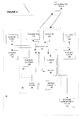
access control system 210 is illustrated as a flow chart. In use, a vehicle user actuates theirAD 226 and a signal is transmitted by one of thereceivers controller 224. In turn, thecontroller 224 sets the look-up value for the latch x to 0 and starts a timer that is associated with thecontroller 224. The look-up values stored bymemory 224 are summarised by Table 1 below.Lock x Time y Latch 0 = Driver 14a side or front passenger door 14d closest to authorisation device 226.Time 0 = 1 s Latch 1 = Passenger door behind either front driver side 14a or front passengerdoor 14d Time 1 = 1 s Latch 2 = Remaining passenger compartment doors Time 2 = 1 s Latch 3 = Storage compartment door 129 - Thus, if the vehicle user approaches the driver's door and actuates their
AD 226, a timer function starts, thecontroller 224 signals thedoor latch 16a to unlock (in a RHD vehicle) immediately thereafter, having determined the direction of approach due to the signal from theAD 226 having been detected byreceiver 212b. Thecontroller 224 then waits a time y which for latch 0 equates to 1 second. If, after this time y, theAD 226 is no longer actuated, thecontroller 224 ends the unlocking procedure. If, however, theAD 226 is still actuated, thecontroller 224 then checks whether the look-up value for latch x is at its maximum value (ie all of the latches have been unlocked). If this is the case thecontroller 224 ends the unlocking procedure. However, if the maximum has not been reached, the controller then refers to the next latch x in the table, which in this case is the latch corresponding to thepassenger door 214b behind the driver's door 214a, and signals the left front door lock actuator to unlock thelatch 216b, and then waits a time y which forlock 1 again equates to 1 second. This procedure is then repeated until either the user has decided that sufficient latches have been unlocked and he/she can thus cease actuating theAD 226, or all of the latches have been unlocked and the procedure also therefore ends. An audible or visible indication (not shown) of the latches that are unlocked may be provided. - Once seated in the vehicle, vehicle users may override the current locked state of any of the closures by actuating the
manual override 230. This may be in the form of a conventional sill button in relation to the vehicle side doors 14a, 14b, 14c, 14d or may be one or more electrical switches actuable by the vehicle user. To lock the vehicle after - It should be understood that numerous changes may be made within the scope of the present invention. For example, the transmitter and receiver may be physically separated from one another. The receivers of the second embodiment may also be mutually separated so as to have, for example, receivers proximate the front, rear and side windows. Rather than determining the location of a person relative to the vehicle, the system of the first embodiment could be used to track the vector of a person walking towards a vehicle and from this determine the appropriate door to be unlocked. The system may also unlatch the closures by being connected to corresponding power latch mechanisms. This would be particularly advantageous in the case of a rear boot/trunk lid as they are often not provided with an external latch release means. The system may enable closures to be unlocked sequentially. For example, a user may first walk to the boot, causing the boot lid to be unlocked, and the subsequentially walk to the driver's door causing this to then be unlocked. The controller may also output to actuators and the like for adjusting the seating, steering wheel and mirror positions, for example, in order to personalise the vehicle settings for a particular user carrying a response device. The system may be retrofittable to vehicles or may be fitted at the time of vehicle manufacture.
- The system may be adapted for vehicles having fewer or more closures than shown in the Figures. Access to the vehicle may be provided by a user supplying biometric data to the vehicle such a fingerprint or a voice input, in which case the term "authorisation device" should be construed to include such data.
Claims (15)
- An access control system (10, 210) for a vehicle (12) having at least two closures (14a, 14b, 14c, 14d, 18) the system comprising a receiving means (112, 212a, 212b, 212c, 212d), the receiving means being so constructed and arranged as to determine the angular position of an associated authorisation device (226) relative to the receiving means thereby enabling the system to determine the appropriate vehicle closure(s) to unlock and/or unlatch, the system being capable of determining additional closures to be unlocked and/or unlatched in accordance with predetermined criteria in response to the period of time for which an input signal is received by the system from the authorisation device.
- A system according to Claim 1 further comprising a controller (24, 224) arranged so as to, in use, signal the unlocking and/or unlatching of at least one closure corresponding to the position of the authorisation device.
- A system according to Claim 1 or Claim 2 wherein the receiving means (112) is directional and rotates so as to determine the angular position of the authorisation device.
- A system according to Claim 3 further comprising a rotary position encoder (120) arranged so as to determine the angular position.
- A system according to Claim 1 or Claim 2 wherein the receiving means (212a, 212b, 212c, 212d) is stationary.
- A system according to Claim 5 wherein the receiving means comprises at least two receivers arranged so as to detect a signal from the identification means over a predetermined angle.
- A system according to Claim 6 wherein three receivers are provided.
- A system according to Claim 6 or Claim 7 wherein first and second receivers (212a, 212c) are capable of receiving signals over angles corresponding substantially to first and second sides of the vehicle respectively.
- A system according to Claims 6 to 8 wherein a third receiver (212b) is capable of receiving signals over an angle corresponding substantially to rear of the vehicle.
- A system according to any one of claims 2 to 9, programmed such that a signal shorter than a first predetermined duration causes the controller to signal the unlocking and/or unlatching of the closure closest to the authorisation device.
- A system according to Claim 10 wherein a signal longer than the first predetermined duration causes the controller to signal the unlocking and/or unlatching of one or more of additional closures.
- A system according to Claim 10 or Claim 11 wherein a signal longer than a second predetermined duration causes the controller to signal the unlocking and/or unlatching of all closures.
- A vehicle incorporating an access control system according to any preceding Claim.
- A method of unlocking and/or unlatching a selected one or more closures (14a, 14b, 14c, 14d, 18) of a vehicle (12) having at least two said closures, the method comprising the steps of:i) providing an access control system (10, 210) comprising receiving means (112, 212a, 212b, 212c, 212d) capable of determining the angular position of an associated authorisation device (26, 226) relative to the receiving means;ii) the receiving means receiving a signal from the authorisation device;iii) the system determining the angle from which the signal was received and the duration of the signal;iv) the system signalling the unlocking and/or unlatching of one or more of the closures in response to the determined angle and signal duration in accordance with predetermined criteria.
- An access control system for a vehicle (12) having at least two closures (14a, 14b, 14c, 14d, 18), the system comprising receiving means (112a, 212a, 212b, 212c, 212d) the receiving means being so construed and arranged as to determine the angular position of an associated authorisation device (26, 226), relative to the receiving means thereby enabling the system to determine the appropriate vehicle closure(s) to unlock and/or unlatch, the system being capable of distinguishing between two levels of authorisation, such that the system is programmed not to signal the locking and/or unlatching of one or more closures irrespective of the relative position of an authorisation device having a first level of authorisation, but does not permit the unlocking or unlatching of the one or more closures in response to an authorisation device having a second level of authorisation.
Applications Claiming Priority (4)
| Application Number | Priority Date | Filing Date | Title |
|---|---|---|---|
| GB0119511 | 2001-08-10 | ||
| GB0119513A GB0119513D0 (en) | 2001-08-10 | 2001-08-10 | Access control system and method |
| GB0119513 | 2001-08-10 | ||
| GB0119511A GB0119511D0 (en) | 2001-08-10 | 2001-08-10 | Access control system and method |
Publications (2)
| Publication Number | Publication Date |
|---|---|
| EP1283503A2 true EP1283503A2 (en) | 2003-02-12 |
| EP1283503A3 EP1283503A3 (en) | 2004-05-26 |
Family
ID=26246427
Family Applications (1)
| Application Number | Title | Priority Date | Filing Date |
|---|---|---|---|
| EP02255481A Ceased EP1283503A3 (en) | 2001-08-10 | 2002-08-06 | Access control system and method |
Country Status (2)
| Country | Link |
|---|---|
| US (1) | US20030038733A1 (en) |
| EP (1) | EP1283503A3 (en) |
Cited By (8)
| Publication number | Priority date | Publication date | Assignee | Title |
|---|---|---|---|---|
| WO2004100081A1 (en) * | 2003-05-07 | 2004-11-18 | Daimlerchrysler Ag | Access authorization system for vehicle comprising at least one keyless go key |
| FR2867503A1 (en) * | 2004-03-15 | 2005-09-16 | Peugeot Citroen Automobiles Sa | Remote control process for locking and unlocking motor vehicle, involves determining attenuation factor to be applied to signal from transmission point such that attenuated wave transmits locking or unlocking control to vehicle |
| EP1659542A1 (en) * | 2004-11-19 | 2006-05-24 | DaimlerChrysler AG | Locking system for a vehicle |
| FR2936545A1 (en) * | 2008-10-01 | 2010-04-02 | Valeo Securite Habitacle | DEVICE FOR AUTOMATICALLY UNLOCKING AN AUTOMATIC VEHICLE OPENING. |
| CN102239508A (en) * | 2008-10-01 | 2011-11-09 | 法雷奥安全座舱公司 | Device for automatically unlocking an openable panel of a motor vehicle |
| CN102903214A (en) * | 2011-07-28 | 2013-01-30 | 富泰华工业(深圳)有限公司 | Car with remote door opening and closing function, remote control system and remote control method |
| EP2704104A1 (en) * | 2012-08-31 | 2014-03-05 | Inventio AG | Inputting lock commands |
| WO2019029782A1 (en) * | 2017-08-07 | 2019-02-14 | Continental Automotive Gmbh | A method for controlling operation of a plurality of vehicle entrances |
Families Citing this family (8)
| Publication number | Priority date | Publication date | Assignee | Title |
|---|---|---|---|---|
| US20030071743A1 (en) * | 2001-10-12 | 2003-04-17 | Singapore Technologies Electronics Limited | Aircraft monitoring and incident management system |
| US7616977B1 (en) * | 2005-01-28 | 2009-11-10 | Scott David Nortman | Method and apparatus for motorized control of an automobile radio cover |
| US20070257772A1 (en) * | 2005-03-17 | 2007-11-08 | Jesse Marcelle | Electronic proximity security system |
| FR2934223A3 (en) * | 2008-07-22 | 2010-01-29 | Renault Sas | Access system detecting device for motor vehicle i.e. car, has environment detecting sensor communicating with identification unit of portable element to identify carrier of element and to predict path or determine location of element |
| US8902040B2 (en) | 2011-08-18 | 2014-12-02 | Greisen Enterprises Llc | Electronic lock and method |
| US10323444B2 (en) * | 2016-10-12 | 2019-06-18 | Ford Global Technologies, Llc | Window short drop for a vehicle with an electronic latch |
| WO2020137929A1 (en) * | 2018-12-25 | 2020-07-02 | 住友電気工業株式会社 | In-vehicle transmission system |
| US11151817B2 (en) * | 2019-11-25 | 2021-10-19 | Ford Global Technologies, Llc | Reducing latency in a passive entry system of a vehicle |
Citations (8)
| Publication number | Priority date | Publication date | Assignee | Title |
|---|---|---|---|---|
| US5278547A (en) * | 1990-01-19 | 1994-01-11 | Prince Corporation | Vehicle systems control with vehicle options programming |
| US5364049A (en) * | 1992-07-15 | 1994-11-15 | Radar Engineers | Vehicular mounting system for directional antennas |
| EP0741221A1 (en) * | 1995-05-03 | 1996-11-06 | Ford Motor Company | Transmitter direction identifier |
| US5929769A (en) * | 1995-10-26 | 1999-07-27 | Valeo Securite Habitacle | Hands-free system for unlocking and/or opening an openable member of a motor vehicle |
| EP0965710A2 (en) * | 1998-06-18 | 1999-12-22 | Toyota Jidosha Kabushiki Kaisha | Vehicle control system |
| US6236333B1 (en) * | 1998-06-17 | 2001-05-22 | Lear Automotive Dearborn, Inc. | Passive remote keyless entry system |
| FR2801550A1 (en) * | 1999-11-30 | 2001-06-01 | Siemens Ag | Car anti-theft mechanism has car-placed transmitter/receiver transmitting modulated signals, and code generator returning code with analyzer measuring code return distance/reflections |
| EP1331147A2 (en) * | 2002-01-24 | 2003-07-30 | ArvinMeritor Light Vehicle Systems (UK) Ltd | Vehicle access control and start system |
Family Cites Families (4)
| Publication number | Priority date | Publication date | Assignee | Title |
|---|---|---|---|---|
| US5252966A (en) * | 1987-05-21 | 1993-10-12 | Trw Inc. | Transmitter for remote control system for door locks |
| US5349459A (en) * | 1992-05-18 | 1994-09-20 | Rockwell International Corporation | Secure remote control system |
| US5532709A (en) * | 1994-11-02 | 1996-07-02 | Ford Motor Company | Directional antenna for vehicle entry system |
| US5619215A (en) * | 1995-07-10 | 1997-04-08 | Her Majesty The Queen In Right Of Canada, As Represented By The Minister Of Communications | Compact antenna steerable in azimuth and elevation |
-
2002
- 2002-08-06 EP EP02255481A patent/EP1283503A3/en not_active Ceased
- 2002-08-08 US US10/215,274 patent/US20030038733A1/en not_active Abandoned
Patent Citations (8)
| Publication number | Priority date | Publication date | Assignee | Title |
|---|---|---|---|---|
| US5278547A (en) * | 1990-01-19 | 1994-01-11 | Prince Corporation | Vehicle systems control with vehicle options programming |
| US5364049A (en) * | 1992-07-15 | 1994-11-15 | Radar Engineers | Vehicular mounting system for directional antennas |
| EP0741221A1 (en) * | 1995-05-03 | 1996-11-06 | Ford Motor Company | Transmitter direction identifier |
| US5929769A (en) * | 1995-10-26 | 1999-07-27 | Valeo Securite Habitacle | Hands-free system for unlocking and/or opening an openable member of a motor vehicle |
| US6236333B1 (en) * | 1998-06-17 | 2001-05-22 | Lear Automotive Dearborn, Inc. | Passive remote keyless entry system |
| EP0965710A2 (en) * | 1998-06-18 | 1999-12-22 | Toyota Jidosha Kabushiki Kaisha | Vehicle control system |
| FR2801550A1 (en) * | 1999-11-30 | 2001-06-01 | Siemens Ag | Car anti-theft mechanism has car-placed transmitter/receiver transmitting modulated signals, and code generator returning code with analyzer measuring code return distance/reflections |
| EP1331147A2 (en) * | 2002-01-24 | 2003-07-30 | ArvinMeritor Light Vehicle Systems (UK) Ltd | Vehicle access control and start system |
Cited By (11)
| Publication number | Priority date | Publication date | Assignee | Title |
|---|---|---|---|---|
| WO2004100081A1 (en) * | 2003-05-07 | 2004-11-18 | Daimlerchrysler Ag | Access authorization system for vehicle comprising at least one keyless go key |
| FR2867503A1 (en) * | 2004-03-15 | 2005-09-16 | Peugeot Citroen Automobiles Sa | Remote control process for locking and unlocking motor vehicle, involves determining attenuation factor to be applied to signal from transmission point such that attenuated wave transmits locking or unlocking control to vehicle |
| EP1659542A1 (en) * | 2004-11-19 | 2006-05-24 | DaimlerChrysler AG | Locking system for a vehicle |
| FR2936545A1 (en) * | 2008-10-01 | 2010-04-02 | Valeo Securite Habitacle | DEVICE FOR AUTOMATICALLY UNLOCKING AN AUTOMATIC VEHICLE OPENING. |
| WO2010037738A1 (en) * | 2008-10-01 | 2010-04-08 | Valeo Securite Habitacle | Device for automatically unlocking an openable panel of a motor vehicle |
| CN102239508A (en) * | 2008-10-01 | 2011-11-09 | 法雷奥安全座舱公司 | Device for automatically unlocking an openable panel of a motor vehicle |
| CN102903214A (en) * | 2011-07-28 | 2013-01-30 | 富泰华工业(深圳)有限公司 | Car with remote door opening and closing function, remote control system and remote control method |
| EP2704104A1 (en) * | 2012-08-31 | 2014-03-05 | Inventio AG | Inputting lock commands |
| WO2014032854A1 (en) * | 2012-08-31 | 2014-03-06 | Inventio Ag | Inputting lock commands |
| US9691202B2 (en) | 2012-08-31 | 2017-06-27 | Inventio Ag | Inputting lock commands |
| WO2019029782A1 (en) * | 2017-08-07 | 2019-02-14 | Continental Automotive Gmbh | A method for controlling operation of a plurality of vehicle entrances |
Also Published As
| Publication number | Publication date |
|---|---|
| EP1283503A3 (en) | 2004-05-26 |
| US20030038733A1 (en) | 2003-02-27 |
Similar Documents
| Publication | Publication Date | Title |
|---|---|---|
| US6552649B1 (en) | Vehicle control system | |
| US6700475B1 (en) | Electronic closure system, in particular a vehicle closure system | |
| EP1283503A2 (en) | Access control system and method | |
| US10212557B2 (en) | Position-based limited-response mode operation in a vehicle communication system | |
| US10158719B2 (en) | Vehicle communication system | |
| US8022808B2 (en) | Vehicle power door control with passive entry | |
| US20070290554A1 (en) | Vehicle control system | |
| KR100638388B1 (en) | Keyless entry device | |
| US7305284B2 (en) | Remote control system and method for vehicle | |
| US6801120B2 (en) | Control apparatus | |
| US20050168322A1 (en) | Method for the remote control of doors and/or lids for vehicles and associated remote control system | |
| US6542071B1 (en) | Opening-closing member control apparatus for vehicle | |
| US7394350B2 (en) | Power-saving on-vehicle controller | |
| US20030222758A1 (en) | Vehicle access control and start system | |
| US9969356B2 (en) | Movement pattern detection in a vehicle communication system | |
| US7683764B2 (en) | Automatic locking failsafe for vehicles with passive keys | |
| JP2000118354A (en) | Vehicle safety system having key-less going action capability | |
| JP2010043525A (en) | Smart-entry system and smart-entry method | |
| JPH112053A (en) | Passive entry control system for vehicle | |
| US6850154B2 (en) | Method and device for protecting motor vehicles against theft | |
| JP2000314259A (en) | Hand-free access device for vehicle | |
| US20060279403A1 (en) | Anti-theft securing method for hands-free vehicle access systems | |
| EP0886025B1 (en) | Vehicle closure systems and method of their controlling | |
| EP1218228B1 (en) | Exterior mounted access device control for a vehicle passive entry system | |
| JP2004084254A (en) | Keyless entry system |
Legal Events
| Date | Code | Title | Description |
|---|---|---|---|
| PUAI | Public reference made under article 153(3) epc to a published international application that has entered the european phase |
Free format text: ORIGINAL CODE: 0009012 |
|
| AK | Designated contracting states |
Designated state(s): AT BE BG CH CY CZ DE DK EE ES FI FR GB GR IE IT LI LU MC NL PT SE SK TR |
|
| AX | Request for extension of the european patent |
Extension state: AL LT LV MK RO SI |
|
| PUAL | Search report despatched |
Free format text: ORIGINAL CODE: 0009013 |
|
| AK | Designated contracting states |
Kind code of ref document: A3 Designated state(s): AT BE BG CH CY CZ DE DK EE ES FI FR GB GR IE IT LI LU MC NL PT SE SK TR |
|
| AX | Request for extension of the european patent |
Extension state: AL LT LV MK RO SI |
|
| 17P | Request for examination filed |
Effective date: 20041112 |
|
| AKX | Designation fees paid |
Designated state(s): DE FR GB |
|
| 17Q | First examination report despatched |
Effective date: 20050228 |
|
| RAP1 | Party data changed (applicant data changed or rights of an application transferred) |
Owner name: MERITOR TECHNOLOGY, INC. |
|
| STAA | Information on the status of an ep patent application or granted ep patent |
Free format text: STATUS: THE APPLICATION HAS BEEN REFUSED |
|
| 18R | Application refused |
Effective date: 20070705 |