EP1283429A2 - Multi band optical system. - Google Patents
Multi band optical system. Download PDFInfo
- Publication number
- EP1283429A2 EP1283429A2 EP02078010A EP02078010A EP1283429A2 EP 1283429 A2 EP1283429 A2 EP 1283429A2 EP 02078010 A EP02078010 A EP 02078010A EP 02078010 A EP02078010 A EP 02078010A EP 1283429 A2 EP1283429 A2 EP 1283429A2
- Authority
- EP
- European Patent Office
- Prior art keywords
- detectors
- dichroic beamsplitter
- beamsplitter cube
- incoming
- optical
- Prior art date
- Legal status (The legal status is an assumption and is not a legal conclusion. Google has not performed a legal analysis and makes no representation as to the accuracy of the status listed.)
- Granted
Links
Images


Classifications
-
- G—PHYSICS
- G02—OPTICS
- G02B—OPTICAL ELEMENTS, SYSTEMS OR APPARATUS
- G02B6/00—Light guides; Structural details of arrangements comprising light guides and other optical elements, e.g. couplings
- G02B6/24—Coupling light guides
- G02B6/42—Coupling light guides with opto-electronic elements
- G02B6/4201—Packages, e.g. shape, construction, internal or external details
- G02B6/4246—Bidirectionally operating package structures
-
- G—PHYSICS
- G02—OPTICS
- G02B—OPTICAL ELEMENTS, SYSTEMS OR APPARATUS
- G02B6/00—Light guides; Structural details of arrangements comprising light guides and other optical elements, e.g. couplings
- G02B6/24—Coupling light guides
- G02B6/26—Optical coupling means
- G02B6/28—Optical coupling means having data bus means, i.e. plural waveguides interconnected and providing an inherently bidirectional system by mixing and splitting signals
- G02B6/293—Optical coupling means having data bus means, i.e. plural waveguides interconnected and providing an inherently bidirectional system by mixing and splitting signals with wavelength selective means
- G02B6/29346—Optical coupling means having data bus means, i.e. plural waveguides interconnected and providing an inherently bidirectional system by mixing and splitting signals with wavelength selective means operating by wave or beam interference
- G02B6/29361—Interference filters, e.g. multilayer coatings, thin film filters, dichroic splitters or mirrors based on multilayers, WDM filters
-
- G—PHYSICS
- G02—OPTICS
- G02B—OPTICAL ELEMENTS, SYSTEMS OR APPARATUS
- G02B6/00—Light guides; Structural details of arrangements comprising light guides and other optical elements, e.g. couplings
- G02B6/24—Coupling light guides
- G02B6/26—Optical coupling means
- G02B6/28—Optical coupling means having data bus means, i.e. plural waveguides interconnected and providing an inherently bidirectional system by mixing and splitting signals
- G02B6/293—Optical coupling means having data bus means, i.e. plural waveguides interconnected and providing an inherently bidirectional system by mixing and splitting signals with wavelength selective means
- G02B6/29379—Optical coupling means having data bus means, i.e. plural waveguides interconnected and providing an inherently bidirectional system by mixing and splitting signals with wavelength selective means characterised by the function or use of the complete device
- G02B6/29395—Optical coupling means having data bus means, i.e. plural waveguides interconnected and providing an inherently bidirectional system by mixing and splitting signals with wavelength selective means characterised by the function or use of the complete device configurable, e.g. tunable or reconfigurable
Definitions
- the present invention relates to the field of optical systems. More specifically it relates to an optical system that receives an incoming beam of electromagnetic radiation, divides the incoming beam into a transmitted beam, containing a part of the wavelength band of the incoming beam, and a reflected beam, containing the remainder of the wavelengths in the incoming beam, transfers the transmitted beam continuously to a detector, and is further capable of switching the reflected beam between any one of two or more detectors.
- Lareau and Partynski describe a dual image reconnaissance camera capable of operating in the visible or infrared spectral bands or in both simultaneously.
- the camera functions by collecting an image with a single objective lens and re-imaging this image into two separate optical channels through a CaFl beam divider/prism.
- Each of the channels contains appropriate optics, including a wafer-scale focal plane array for capturing images in the appropriate region of the optical spectrum (Lareau and Partynski, Dual band framing cameras: technology and status, Proceedings of SPIE, Vol. 4127 (2000) 148-150).
- US 5,512,750 discloses another method of producing simultaneous images in two different wavelength regions.
- sensors producing simultaneous, superimposed, two-dimensional images in two IR bands with the dual band detector arrays monolithically integrated upon a common substrate are described.
- the incoming infrared image is viewed simultaneously in the medium and long wave infrared bands.
- optical systems Another useful property of optical systems is the ability to switch an image from one optical track to another, enabling the image to be viewed at different locations, with different types of detectors, and even in different spectral regions, according to the decision of the operator of the system.
- a common method of accomplishing this is to make use of switching mirrors that are moved in and out of the optical path to direct the beam to different directions.
- Typical optical arrangements of this sort are described in: Lloyd, JM, Thermal Imaging Systems, Plenum Press, New York and London, 1982, p.256.
- optical systems containing both of these properties do not exist.
- Such a combination would be especially useful, for example, for a system comprising a video camera combined with a laser range finder and a laser designator receiver or for an optical communication system in which fiber optical components replace the optical detectors.
- the invention is directed towards an optical system for receiving an incoming beam of electromagnetic radiation, for dividing it into a transmitted beam, containing a part of the wavelength band of the incoming beam, and a reflected beam, containing the remainder of the wavelengths in the incoming beam.
- the optical system transfers the transmitted beam continuously to a detector, while being further capable of switching the reflected beam between any one of two or more detectors.
- the system comprises:
- the invention is directed toward a communication system that receives an incoming signal, divides the incoming signal into a transmitted signal, containing a part of the wavelength band of the incoming signal, and a reflected signal, containing the remainder of the wavelengths in the incoming signal.
- the system transfers the transmitted signal continuously to fiber optical elements, and is further capable of switching the reflected signal between any one of two or more fiber optical elements.
- the communication system of the invention comprises:
- the invention is directed towards a method for dividing an incoming beam of electromagnetic radiation into a transmitted beam, containing a part of the wavelength band of the incoming beam, and a reflected beam, containing the remainder of the wavelengths in the incoming beam.
- the method transfers the transmitted beam continuously to a detector, and switches the reflected beam between any one of two or more detectors.
- the method consists of the following steps:
- Fig. 1A is a schematic top view showing the basic embodiment of the optical system of the invention.
- An incoming light beam generally indicated by numeral 1
- a rotatable dichroic beamsplitter cube 3 is centered on the optical axis (Z) of the system, between the objective lens and the focal point.
- Part of the energy of the beam lying within a certain wavelength region, passes directly through the cube, falling on detector 4.
- the remainder of the energy of the beam (except for losses due to absorption or unwanted reflections), lying in a different wavelength range, is reflected, falling onto detector 5.
- Rotating the cube by 90° counterclockwise about an axis perpendicular to the plane of the figure will cause the reflected part of the incoming beam top fall on detector 6.
- Rotating the cube in this manner places limitations on the system, for example on the number of detectors that can be placed around the dichroic beamsplitter cube and in their locations.
- the cube is rotated around the optical (Z) axis.
- the focal point of the reflected beam traces out a circle, surrounding the cube, in a plane perpendicular to the plane of the paper with its center located at the intersection of the plane with the optical axis. Detectors can be placed at any position on this circle.
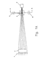
- Fig. 1B is a cross section in the AA plane of Fig. 1A that illustrates this preferred embodiment.
- Numeral 3 designates the dichroic beamsplitter cube.
- the detectors of Fig. 1 are shown at 5 and 6 and numeral 7 designates additional detectors that can be placed on the circle surrounding the cube.
- the number of detectors that can be used will depend on the size of the detectors and the distance from the center of the cube to the focal point of the objective lens.
- additional optics such as coupling lenses and optical fibers
- placing static lenses in front of the detectors allows control of the optical focal length of each channel and determines the field of view.
- the system of the invention can operate in the ultraviolet and/or visible and/or infrared regions if suitable materials are chosen for constructing the optical elements.
- the ratio of transmitted to reflected energy and the division of the wavelength range of the incident beam into the ranges of the direct and reflected beams depends upon the properties of the reflective surface of the beamsplitter cube. The considerations necessary to make these design decisions are well known to the man of the art and will not be further discussed herein for the sake of brevity.
- Fig. 2 shows the dichroic cube 3.
- the cube is made by gluing together two triangular right prisms, 21 and 23. Before gluing the prisms together, a dielectric-dichroic partially reflecting coating is applied to the diagonal face of one of the prisms.
- the dashed line 23 represents such a layer applied to the surface of prism 21.
- the material of the cube and the coatings are chosen to give it broadband transmission over the desired wavelength range.
- the dichroic reflecting layer is designed to selectively reflect specific wavelengths in the incident beam while transmitting the remainder. Also the ratio of reflected to transmitted energy can be adjusted.
- the faces through which the light beams pass are coated with a broadband anti-reflective coating and there is some energy loss due to absorption in the coating layer.
- Fig. 2 illustrates the division of a beam composed of a range of wavelengths ⁇ that is divided into two groups of wavelengths ⁇ 1 and ⁇ 2 that travel in mutually perpendicular directions after encountering the reflective layer in the dichroic cube 3.
- Fig. 3 is a schematic graph showing the variation of reflectance with wavelength for a typical dielectric coating that forms the reflecting layer of the dichroic cube.
- a light beam comprising wavelengths ⁇ in the visible and near infrared range (for example 0.45 - 1.2 ⁇ m) passes through a dichroic beamsplitter cube having a reflecting layer characterized by the graph of Fig.3.
- a relatively narrow band of wavelengths centered at about 1.05 ⁇ m will be reflected at the layer to form ⁇ 2 .
- the remainder of the wavelengths will travel through the cube undisturbed and will constitute the beam ⁇ 1 .
- the system is extremely flexible and can be built to operate in any wavelength region by using either especially designed components or readily available off-the-shelf items.
- the following components could be assembled to create an optical system for continuous observation of a scene in the visible wavelengths while switching the same image of the scene in the near infrared between two detectors. Referring to Fig. 1A:
- system of the invention can also be used in communication systems. Replacing the detectors in the embodiments described above with fiber optical elements results in a system providing one continuous channel of communication and a second channel, carrying identical information that, by rotation of the dichroic cube beamsplitter, can be switched between different data links.
- the methods and optical elements necessary to construct and operate this embodiment of the invention are well known in the art and will not be further discussed here.
Abstract
Description
- The present invention relates to the field of optical systems. More specifically it relates to an optical system that receives an incoming beam of electromagnetic radiation, divides the incoming beam into a transmitted beam, containing a part of the wavelength band of the incoming beam, and a reflected beam, containing the remainder of the wavelengths in the incoming beam, transfers the transmitted beam continuously to a detector, and is further capable of switching the reflected beam between any one of two or more detectors.
- Many different optical systems have been devised for enabling the simultaneous observation of an optical signal or scene in more than one wavelength region. For example, Lareau and Partynski describe a dual image reconnaissance camera capable of operating in the visible or infrared spectral bands or in both simultaneously. The camera functions by collecting an image with a single objective lens and re-imaging this image into two separate optical channels through a CaFl beam divider/prism. Each of the channels contains appropriate optics, including a wafer-scale focal plane array for capturing images in the appropriate region of the optical spectrum (Lareau and Partynski,Dual band framing cameras: technology and status, Proceedings of SPIE, Vol. 4127 (2000) 148-150).
- US 5,512,750 discloses another method of producing simultaneous images in two different wavelength regions. In this case, sensors producing simultaneous, superimposed, two-dimensional images in two IR bands with the dual band detector arrays monolithically integrated upon a common substrate are described. Here the incoming infrared image is viewed simultaneously in the medium and long wave infrared bands.
- Another useful property of optical systems is the ability to switch an image from one optical track to another, enabling the image to be viewed at different locations, with different types of detectors, and even in different spectral regions, according to the decision of the operator of the system. A common method of accomplishing this is to make use of switching mirrors that are moved in and out of the optical path to direct the beam to different directions. Typical optical arrangements of this sort are described in: Lloyd, JM, Thermal Imaging Systems, Plenum Press, New York and London, 1982, p.256.
- Although it would be advantageous for many applications to be able to provide optical systems with both properties, i.e. the ability to simultaneously observe the same image in different wavelength regions and also to switch at least one of the images between different detectors, to date optical systems containing both of these properties do not exist. Such a combination would be especially useful, for example, for a system comprising a video camera combined with a laser range finder and a laser designator receiver or for an optical communication system in which fiber optical components replace the optical detectors.
- It is therefore a purpose of the present invention to provide an optical system that receives an incoming beam of electromagnetic radiation, divides the incoming beam into a transmitted beam, containing a part of the wavelength band, and a reflected beam, containing the remainder of the wavelengths, transfers the transmitted beam continuously to a detector, and is further capable of switching the reflected beam between any one of two or more detectors.
- It is a further purpose of the present invention to provide a communication system that receives an incoming signal, divides the incoming signal into a transmitted signal, containing a part of the wavelength band, and a reflected signal, containing the remainder of the wavelengths, transfers the transmitted signal continuously to fiber optical elements, and is further capable of switching the reflected signal between any one of two or more fiber optical elements.
- Further purposes and advantages of this invention will appear as the description proceeds.
- In a first aspect the invention is directed towards an optical system for receiving an incoming beam of electromagnetic radiation, for dividing it into a transmitted beam, containing a part of the wavelength band of the incoming beam, and a reflected beam, containing the remainder of the wavelengths in the incoming beam. The optical system transfers the transmitted beam continuously to a detector, while being further capable of switching the reflected beam between any one of two or more detectors. The system comprises:
- an objective lens;
- a dichroic beamsplitter cube;
- a first detector, capable of detecting radiation in a first wavelength band;
- a second group of two or more detectors, each capable of detecting radiation in a second wavelength band; and
- a means of rotating the dichroic beamsplitter cube in order to switch between the detectors of the second group.
- In a second aspect the invention is directed toward a communication system that receives an incoming signal, divides the incoming signal into a transmitted signal, containing a part of the wavelength band of the incoming signal, and a reflected signal, containing the remainder of the wavelengths in the incoming signal. The system transfers the transmitted signal continuously to fiber optical elements, and is further capable of switching the reflected signal between any one of two or more fiber optical elements. The communication system of the invention comprises:
- an objective lens;
- a dichroic beamsplitter cube;
- a first fiber optical element, capable of transferring signals in a first wavelength band;
- a second group of two or more fiber optical elements, each capable of conducting signals in a second wavelength band; and
- a means of rotating the dichroic beamsplitter cube in order to switch between the fiber optical elements of the second group.
- In a further aspect, the invention is directed towards a method for dividing an incoming beam of electromagnetic radiation into a transmitted beam, containing a part of the wavelength band of the incoming beam, and a reflected beam, containing the remainder of the wavelengths in the incoming beam. The method transfers the transmitted beam continuously to a detector, and switches the reflected beam between any one of two or more detectors. The method consists of the following steps:
- passing the incoming beam through an objective lens;
- placing a dichroic beamsplitter cube on the optical axis of the objective lens at a location between the lens and its focal point;
- placing a first detector, capable of detecting radiation in a first wavelength band, at the focal point of the transmitted beam;
- placing a second group of two or more detectors, each capable of detecting radiation in a second wavelength band at the focal point of the reflected beam; and
- providing a means of rotating the dichroic beamsplitter cube in order to switch between the detectors of the second group.
- In all of the aspects of the invention:
- the incoming beam can consists of radiation in the ultraviolet and/or visible and/or infrared regions of the electromagnetic spectrum;
- the dichroic beamsplitter cube is made by gluing together two triangular right prisms one of the prisms having a dielectric coating (partially reflecting layer) applied to its diagonal face before gluing and having the faces of the dichroic beamsplitter cube, through which the light beams pass, coated with broadband antireflective coatings;
- the dichroic beamsplitter cube can be rotated either about the optical axis of the system with the focal point of the reflected beam moving in a plane perpendicular to the optical axis or the dichroic beamsplitter cube can be rotated about an axis perpendicular to the optical axis of the system with the focal point of the reflected beam moving in the plane containing the optical axis;
- static lenses can be placed in front of some or all of the detectors thereby allowing control of the optical focal length and the field of view; and
- some or all of the detectors can be replaced with fiber optical elements. All the above and other characteristics and advantages of the invention will be further understood through the following illustrative and non-limitative description of preferred embodiments thereof, with reference to the appended drawings.
-
- Fig. 1A is a schematic top view showing the basic embodiment of the optical system of the invention
- Fig. 1B is a cross section in the AA plane of Fig. 1A;
- Fig. 2 schematically shows the dichroic beamsplitter cube; and
- Fig. 3 is a schematic graph showing the variation of reflectance with wavelength for a typical dielectric-dichroic reflecting coating that forms the partially reflecting layer of the dichroic cube.
- The invention will now be further explained through the illustrative and non-limitative description of preferred embodiments. Fig. 1A is a schematic top view showing the basic embodiment of the optical system of the invention. An incoming light beam, generally indicated by numeral 1, is focused by
objective lens 2. A rotatabledichroic beamsplitter cube 3 is centered on the optical axis (Z) of the system, between the objective lens and the focal point. Part of the energy of the beam, lying within a certain wavelength region, passes directly through the cube, falling on detector 4. The remainder of the energy of the beam (except for losses due to absorption or unwanted reflections), lying in a different wavelength range, is reflected, falling ontodetector 5. Rotating the cube by 90° counterclockwise about an axis perpendicular to the plane of the figure will cause the reflected part of the incoming beam top fall ondetector 6. - Rotating the cube in this manner places limitations on the system, for example on the number of detectors that can be placed around the dichroic beamsplitter cube and in their locations. To overcome these restrictions, in a preferred embodiment of the invention, the cube is rotated around the optical (Z) axis. In this case, the focal point of the reflected beam traces out a circle, surrounding the cube, in a plane perpendicular to the plane of the paper with its center located at the intersection of the plane with the optical axis. Detectors can be placed at any position on this circle.
- Fig. 1B is a cross section in the AA plane of Fig. 1A that illustrates this preferred embodiment.
Numeral 3 designates the dichroic beamsplitter cube. The detectors of Fig. 1 are shown at 5 and 6 andnumeral 7 designates additional detectors that can be placed on the circle surrounding the cube. - Persons familiar with the art will understand that the number of detectors that can be used will depend on the size of the detectors and the distance from the center of the cube to the focal point of the objective lens. By the use of additional optics, such as coupling lenses and optical fibers, it is possible to place the detectors a distance remote from the cube and at the same time increase their number if necessary for a particular application. In addition, placing static lenses in front of the detectors allows control of the optical focal length of each channel and determines the field of view.
- The system of the invention can operate in the ultraviolet and/or visible and/or infrared regions if suitable materials are chosen for constructing the optical elements. The ratio of transmitted to reflected energy and the division of the wavelength range of the incident beam into the ranges of the direct and reflected beams depends upon the properties of the reflective surface of the beamsplitter cube. The considerations necessary to make these design decisions are well known to the man of the art and will not be further discussed herein for the sake of brevity.
- Fig. 2 shows the
dichroic cube 3. The cube is made by gluing together two triangular right prisms, 21 and 23. Before gluing the prisms together, a dielectric-dichroic partially reflecting coating is applied to the diagonal face of one of the prisms. In Fig. 2, the dashedline 23, represents such a layer applied to the surface ofprism 21. The material of the cube and the coatings are chosen to give it broadband transmission over the desired wavelength range. The dichroic reflecting layer is designed to selectively reflect specific wavelengths in the incident beam while transmitting the remainder. Also the ratio of reflected to transmitted energy can be adjusted. Typically the faces through which the light beams pass are coated with a broadband anti-reflective coating and there is some energy loss due to absorption in the coating layer. - Fig. 2 illustrates the division of a beam composed of a range of wavelengths λ that is divided into two groups of wavelengths λ1 and λ2 that travel in mutually perpendicular directions after encountering the reflective layer in the
dichroic cube 3. - Fig. 3 is a schematic graph showing the variation of reflectance with wavelength for a typical dielectric coating that forms the reflecting layer of the dichroic cube. Referring to Fig. 2, a light beam comprising wavelengths λ in the visible and near infrared range (for example 0.45 - 1.2µm) passes through a dichroic beamsplitter cube having a reflecting layer characterized by the graph of Fig.3. A relatively narrow band of wavelengths centered at about 1.05µm will be reflected at the layer to form λ2. The remainder of the wavelengths will travel through the cube undisturbed and will constitute the beam λ1.
- As can be appreciated by the man of the art, the system is extremely flexible and can be built to operate in any wavelength region by using either especially designed components or readily available off-the-shelf items. As an illustrative and non-limitative example, the following components could be assembled to create an optical system for continuous observation of a scene in the visible wavelengths while switching the same image of the scene in the near infrared between two detectors. Referring to Fig. 1A:
- Objective lens (2) - Achromat Lens H45354 (Edmund Scientific Company)
- Dichroic beamsplitter cube (3) - BNPB-20B coated with a BC R1064/T532 P4 dichroic layer(lambda Research Optics, Inc.)
- Detector (4) - Monochrome CCD camera XC-75 (Sony Corp.)
- Detectors (5 and 6) - Passive photodiode detectors E10RUV or E3RIR (Linos Photonics).
- In another embodiment, the system of the invention can also be used in communication systems. Replacing the detectors in the embodiments described above with fiber optical elements results in a system providing one continuous channel of communication and a second channel, carrying identical information that, by rotation of the dichroic cube beamsplitter, can be switched between different data links. The methods and optical elements necessary to construct and operate this embodiment of the invention are well known in the art and will not be further discussed here.
- The means of mounting the optical elements and rotating the beamsplitter cube to effect the switching between detectors are conventional and well known in the art. Therefore, they will not be further described here in the interest of brevity.
- Although embodiments of the invention have been described by way of illustration, it will be understood that the invention may be carried out with many variations, modifications, and adaptations, without departing from its spirit or exceeding the scope of the claims.
Claims (17)
- An optical system for receiving an incoming beam of electromagnetic radiation, for dividing it into a transmitted beam, containing a part of the wavelength band of said incoming beam, and a reflected beam, containing the remainder of the wavelengths in said incoming beam, and for transferring said transmitted beam continuously to a detector, said system being further capable of switching said reflected beam between any one of two or more detectors, said system comprising:an objective lens;a dichroic beamsplitter cube;a first detector, capable of detecting radiation in a first wavelength band;a second group of two or more detectors, each capable of detecting radiation in a second wavelength band; anda means of rotating said dichroic beamsplitter cube in order to switch between said detectors of said second group.
- An optical system, according to claim 1, wherein the incoming beam consists of radiation in the ultraviolet and/or visible and/or infrared regions of the electromagnetic spectrum.
- An optical system, according to claim 1, wherein the dichroic beamsplitter cube is rotated about the optical axis of said system and the focal point of the reflected beam moves in a plane, said plane being perpendicular to said optical axis.
- An optical system, according to claim 1, wherein the dichroic beamsplitter cube is rotated about an axis perpendicular to the optical axis of said system and the focal point of the reflected beam moves in the plane containing said optical axis.
- An optical system, according to claim 1, wherein the dichroic beamsplitter cube is made by gluing together two triangular right prisms one of said prisms having a dielectric coating (partially reflecting layer) applied to its diagonal face before gluing.
- An optical system, according to claim 1, wherein the faces of the dichroic beamsplitter cube through which the light beams pass are coated with broadband antireflective coatings.
- An optical system, according to claim 1, wherein static lenses are placed in front of some or all of the detectors thereby allowing control of the optical focal length and the field of view.
- An optical system, according to claim 1, wherein some or all of the detectors are replaced with fiber optical elements.
- A communication system that receives an incoming signal, divides said incoming signal into a transmitted signal, containing a part of the wavelength band of said incoming signal, and a reflected signal, containing the remainder of the wavelengths in said incoming signal, transfers said transmitted signal continuously to fiber optical elements, and is further capable of switching said reflected signal between any one of two or more fiber optical elements, comprising:an objective lens;a dichroic beamsplitter cube;a first fiber optical element, capable of transferring signals in a first wavelength band;a second group of two or more fiber optical elements, each capable of conducting signals in a second wavelength band; anda means of rotating said dichroic beamsplitter cube in order to switch between said fiber optical elements of said second group.
- A method for dividing an incoming beam of electromagnetic radiation into a transmitted beam, containing a part of the wavelength band of said incoming beam, and a reflected beam, containing the remainder of the wavelengths in said incoming beam, transferring said transmitted beam continuously to a detector, and switching said reflected beam between any one of two or more detectors consisting of the following steps:passing said incoming beam through an objective lens;placing a dichroic beamsplitter cube on the optical axis of said objective lens at a location between said lens and its focal point;placing a first detector, capable of detecting radiation in a first wavelength band, at the focal point of said transmitted beam;placing a second group of two or more detectors, each capable of detecting radiation in a second wavelength band at the focal point of said reflected beam; andproviding a means of rotating said dichroic beamsplitter cube in order to switch between said detectors of said second group.
- A method, according to claim 10, wherein the incoming beam consists of radiation in the ultraviolet and/or visible and/or infrared regions of the electromagnetic spectrum.
- A method, according to claim 10, wherein the dichroic beamsplitter cube is rotated about the optical axis of said system and the focal point of the reflected beam moves in a plane, said plane being perpendicular to said optical axis.
- A method, according to claim 10, wherein the dichroic beamsplitter cube is rotated about an axis perpendicular to the optical axis of said system and the focal point of the reflected beam is located in the plane containing said optical axis.
- A method, according to claim 10, wherein the dichroic beamsplitter cube is made by gluing together two triangular right prisms one of said prisms having a dielectric coating (partially reflecting layer) applied to its diagonal face before gluing.
- A method, according to claim 10, wherein the faces of the dichroic beamsplitter cube through which the light beams pass are coated with broadband antireflective coatings.
- A method, according to claim 10, wherein static lenses are placed in front of some or all of the detectors thereby allowing control of the optical focal length and the field of view.
- A method, according to claim 10, wherein some or all of the detectors are replaced with fiber optical elements.
Applications Claiming Priority (2)
| Application Number | Priority Date | Filing Date | Title |
|---|---|---|---|
| IL144639A IL144639A (en) | 2001-07-30 | 2001-07-30 | Multiband optical system |
| IL14463901 | 2001-07-30 |
Publications (3)
| Publication Number | Publication Date |
|---|---|
| EP1283429A2 true EP1283429A2 (en) | 2003-02-12 |
| EP1283429A3 EP1283429A3 (en) | 2004-10-13 |
| EP1283429B1 EP1283429B1 (en) | 2008-09-10 |
Family
ID=11075654
Family Applications (1)
| Application Number | Title | Priority Date | Filing Date |
|---|---|---|---|
| EP02078010A Expired - Lifetime EP1283429B1 (en) | 2001-07-30 | 2002-07-23 | Multi band optical system. |
Country Status (5)
| Country | Link |
|---|---|
| US (1) | US6952010B2 (en) |
| EP (1) | EP1283429B1 (en) |
| AT (1) | ATE408162T1 (en) |
| DE (1) | DE60228798D1 (en) |
| IL (1) | IL144639A (en) |
Cited By (3)
| Publication number | Priority date | Publication date | Assignee | Title |
|---|---|---|---|---|
| US7701638B2 (en) | 2008-01-30 | 2010-04-20 | The United States Of America As Represented By The Secretary Of The Army | Spherically shaped optical beamsplitter |
| US7848024B2 (en) * | 2008-01-30 | 2010-12-07 | The United States Of America As Represented By The Secretary Of The Army | Cylindrically shaped optical beamsplitter |
| WO2022207140A1 (en) * | 2021-03-31 | 2022-10-06 | Continental Automotive Technologies GmbH | An imaging device for a driver monitoring system |
Families Citing this family (10)
| Publication number | Priority date | Publication date | Assignee | Title |
|---|---|---|---|---|
| US6969856B1 (en) * | 2003-06-19 | 2005-11-29 | The United States Of America As Represented By The Secretary Of The Navy | Two band imaging system |
| CN101382659B (en) * | 2007-09-07 | 2010-09-29 | 鸿富锦精密工业(深圳)有限公司 | Total internal reflection prism system and method for manufacturing same |
| US7952688B2 (en) * | 2008-06-10 | 2011-05-31 | Raytheon Company | Multi-waveband sensor system and methods for seeking targets |
| US8766191B2 (en) * | 2009-10-06 | 2014-07-01 | The Curators Of The University Of Missouri | External/internal optical adapter for FTIR spectrophotometer |
| US8665421B1 (en) * | 2010-04-19 | 2014-03-04 | Bae Systems Information And Electronic Systems Integration Inc. | Apparatus for providing laser countermeasures to heat-seeking missiles |
| US9631973B2 (en) * | 2013-12-13 | 2017-04-25 | Raytheon Company | Multifunction imager |
| JP6339644B2 (en) * | 2016-10-19 | 2018-06-06 | ファナック株式会社 | Beam distributor |
| JP6306659B1 (en) * | 2016-10-19 | 2018-04-04 | ファナック株式会社 | Beam distributor |
| US20210368080A1 (en) * | 2018-08-09 | 2021-11-25 | Corephotonics Ltd. | Multi-cameras with shared camera apertures |
| CN111678868A (en) * | 2020-05-10 | 2020-09-18 | 陈绩 | Multi-light-path switching device and method and spectrum detection device |
Citations (4)
| Publication number | Priority date | Publication date | Assignee | Title |
|---|---|---|---|---|
| US5367399A (en) * | 1992-02-13 | 1994-11-22 | Holotek Ltd. | Rotationally symmetric dual reflection optical beam scanner and system using same |
| US5420946A (en) * | 1993-03-09 | 1995-05-30 | Tsai; Jian-Hung | Multiple channel optical coupling switch |
| WO1999002950A1 (en) * | 1997-07-12 | 1999-01-21 | Optical Insights, Llc | Multi-spectral two-dimensional imaging spectrometer |
| US5900942A (en) * | 1997-09-26 | 1999-05-04 | The United States Of America As Represented By Administrator Of National Aeronautics And Space Administration | Multi spectral imaging system |
Family Cites Families (3)
| Publication number | Priority date | Publication date | Assignee | Title |
|---|---|---|---|---|
| DE3939551A1 (en) * | 1989-11-30 | 1991-06-06 | Linotype Ag | OPTICAL POSITIONING SYSTEM FOR AT LEAST ONE PICTURE POINT |
| US5512750A (en) | 1994-06-03 | 1996-04-30 | Martin Marietta Corporation | A-dual band IR sensor having two monolithically integrated staring detector arrays for simultaneous, coincident image readout |
| JPH10199016A (en) * | 1997-01-08 | 1998-07-31 | Toshiba Corp | Optical head device for optical disk player |
-
2001
- 2001-07-30 IL IL144639A patent/IL144639A/en not_active IP Right Cessation
-
2002
- 2002-07-23 DE DE60228798T patent/DE60228798D1/en not_active Expired - Fee Related
- 2002-07-23 AT AT02078010T patent/ATE408162T1/en not_active IP Right Cessation
- 2002-07-23 EP EP02078010A patent/EP1283429B1/en not_active Expired - Lifetime
- 2002-07-23 US US10/202,548 patent/US6952010B2/en not_active Expired - Fee Related
Patent Citations (4)
| Publication number | Priority date | Publication date | Assignee | Title |
|---|---|---|---|---|
| US5367399A (en) * | 1992-02-13 | 1994-11-22 | Holotek Ltd. | Rotationally symmetric dual reflection optical beam scanner and system using same |
| US5420946A (en) * | 1993-03-09 | 1995-05-30 | Tsai; Jian-Hung | Multiple channel optical coupling switch |
| WO1999002950A1 (en) * | 1997-07-12 | 1999-01-21 | Optical Insights, Llc | Multi-spectral two-dimensional imaging spectrometer |
| US5900942A (en) * | 1997-09-26 | 1999-05-04 | The United States Of America As Represented By Administrator Of National Aeronautics And Space Administration | Multi spectral imaging system |
Non-Patent Citations (1)
| Title |
|---|
| LAREAU A G ET AL: "Dual-band framing cameras: technology and status" PROC. SPIE - INT. SOC. OPT. ENG. (USA), PROCEEDINGS OF THE SPIE - THE INTERNATIONAL SOCIETY FOR OPTICAL ENGINEERING, 2000, SPIE-INT. SOC. OPT. ENG, USA, vol. 4127, 2000, pages 148-156, XP002292361 ISSN: 0277-786X * |
Cited By (4)
| Publication number | Priority date | Publication date | Assignee | Title |
|---|---|---|---|---|
| US7701638B2 (en) | 2008-01-30 | 2010-04-20 | The United States Of America As Represented By The Secretary Of The Army | Spherically shaped optical beamsplitter |
| US7848024B2 (en) * | 2008-01-30 | 2010-12-07 | The United States Of America As Represented By The Secretary Of The Army | Cylindrically shaped optical beamsplitter |
| WO2022207140A1 (en) * | 2021-03-31 | 2022-10-06 | Continental Automotive Technologies GmbH | An imaging device for a driver monitoring system |
| GB2605768A (en) * | 2021-03-31 | 2022-10-19 | Continental Automotive Gmbh | An imaging device for a driver monitoring system |
Also Published As
| Publication number | Publication date |
|---|---|
| IL144639A0 (en) | 2003-06-24 |
| US6952010B2 (en) | 2005-10-04 |
| DE60228798D1 (en) | 2008-10-23 |
| US20030053181A1 (en) | 2003-03-20 |
| EP1283429B1 (en) | 2008-09-10 |
| IL144639A (en) | 2006-08-20 |
| EP1283429A3 (en) | 2004-10-13 |
| ATE408162T1 (en) | 2008-09-15 |
Similar Documents
| Publication | Publication Date | Title |
|---|---|---|
| US7796316B2 (en) | Micro-optic shutter | |
| EP0490497B1 (en) | Simultaneous dual field of view sensor | |
| JP4936554B2 (en) | Prism device and optical and radio frequency combined beam steering system | |
| US6952010B2 (en) | Optical system and method for switching sensor channels while simultaneously viewing a scene in a different wavelength range | |
| JPS62234106A (en) | Beam splitter | |
| US20180267282A1 (en) | Wide spectrum optical systems and devices implementing first surface mirrors | |
| US6909539B2 (en) | System and method for combining multiple energy bands to improve scene viewing | |
| US4527055A (en) | Apparatus for selectively viewing either of two scenes of interest | |
| EP0816891B1 (en) | Integrated panoramic and high resolution sensor optics | |
| KR100914094B1 (en) | Lightweight laser designator ranger flir optics | |
| KR101649774B1 (en) | Extreme broadband compact optical system with multiple fields of view | |
| JP2954095B2 (en) | Image sensor with multiple fields of view and using only reflective optical elements | |
| WO2011100674A1 (en) | Improved optical image system | |
| US5135183A (en) | Dual-image optoelectronic imaging apparatus including birefringent prism arrangement | |
| US5225893A (en) | Two-color focal plane array sensor arrangement | |
| US5149970A (en) | Dual-band optoelectronic imaging apparatus including "venetian blind" dichroic plate arrangement | |
| US8059344B2 (en) | Multi-band lens | |
| US7408159B1 (en) | Dual infrared band objective lens | |
| JP2002318157A (en) | Electromagnetic wave detection device | |
| WO2007015236A1 (en) | Dual field of view optics | |
| GB2305573A (en) | High-speed optronic panoramic surveillance system | |
| US11644542B2 (en) | Optical sensor with MEMS MMA steered transmitter and staring detector | |
| KR102494971B1 (en) | Electro-optical tracking apparatus and Close-In Weapon System comprising the same | |
| GB2323681A (en) | Combined laser system and infra-red imaging system | |
| CN110568419A (en) | Receiving device for laser radar system |
Legal Events
| Date | Code | Title | Description |
|---|---|---|---|
| PUAI | Public reference made under article 153(3) epc to a published international application that has entered the european phase |
Free format text: ORIGINAL CODE: 0009012 |
|
| AK | Designated contracting states |
Designated state(s): AT BE BG CH CY CZ DE DK EE ES FI FR GB GR IE IT LI LU MC NL PT SE SK TR |
|
| AX | Request for extension of the european patent |
Extension state: AL LT LV MK RO SI |
|
| PUAL | Search report despatched |
Free format text: ORIGINAL CODE: 0009013 |
|
| AK | Designated contracting states |
Kind code of ref document: A3 Designated state(s): AT BE BG CH CY CZ DE DK EE ES FI FR GB GR IE IT LI LU MC NL PT SE SK TR |
|
| AX | Request for extension of the european patent |
Extension state: AL LT LV MK RO SI |
|
| 17P | Request for examination filed |
Effective date: 20050321 |
|
| AKX | Designation fees paid |
Designated state(s): AT BE BG CH CY CZ DE DK EE ES FI FR GB GR IE IT LI LU MC NL PT SE SK TR |
|
| GRAP | Despatch of communication of intention to grant a patent |
Free format text: ORIGINAL CODE: EPIDOSNIGR1 |
|
| GRAS | Grant fee paid |
Free format text: ORIGINAL CODE: EPIDOSNIGR3 |
|
| GRAA | (expected) grant |
Free format text: ORIGINAL CODE: 0009210 |
|
| AK | Designated contracting states |
Kind code of ref document: B1 Designated state(s): AT BE BG CH CY CZ DE DK EE ES FI FR GB GR IE IT LI LU MC NL PT SE SK TR |
|
| REG | Reference to a national code |
Ref country code: GB Ref legal event code: FG4D |
|
| REG | Reference to a national code |
Ref country code: CH Ref legal event code: EP |
|
| REG | Reference to a national code |
Ref country code: IE Ref legal event code: FG4D |
|
| REF | Corresponds to: |
Ref document number: 60228798 Country of ref document: DE Date of ref document: 20081023 Kind code of ref document: P |
|
| PG25 | Lapsed in a contracting state [announced via postgrant information from national office to epo] |
Ref country code: FI Free format text: LAPSE BECAUSE OF FAILURE TO SUBMIT A TRANSLATION OF THE DESCRIPTION OR TO PAY THE FEE WITHIN THE PRESCRIBED TIME-LIMIT Effective date: 20080910 Ref country code: AT Free format text: LAPSE BECAUSE OF FAILURE TO SUBMIT A TRANSLATION OF THE DESCRIPTION OR TO PAY THE FEE WITHIN THE PRESCRIBED TIME-LIMIT Effective date: 20080910 |
|
| NLV1 | Nl: lapsed or annulled due to failure to fulfill the requirements of art. 29p and 29m of the patents act | ||
| PG25 | Lapsed in a contracting state [announced via postgrant information from national office to epo] |
Ref country code: BE Free format text: LAPSE BECAUSE OF FAILURE TO SUBMIT A TRANSLATION OF THE DESCRIPTION OR TO PAY THE FEE WITHIN THE PRESCRIBED TIME-LIMIT Effective date: 20080910 |
|
| PG25 | Lapsed in a contracting state [announced via postgrant information from national office to epo] |
Ref country code: BG Free format text: LAPSE BECAUSE OF FAILURE TO SUBMIT A TRANSLATION OF THE DESCRIPTION OR TO PAY THE FEE WITHIN THE PRESCRIBED TIME-LIMIT Effective date: 20081210 Ref country code: ES Free format text: LAPSE BECAUSE OF FAILURE TO SUBMIT A TRANSLATION OF THE DESCRIPTION OR TO PAY THE FEE WITHIN THE PRESCRIBED TIME-LIMIT Effective date: 20081221 |
|
| PG25 | Lapsed in a contracting state [announced via postgrant information from national office to epo] |
Ref country code: SK Free format text: LAPSE BECAUSE OF FAILURE TO SUBMIT A TRANSLATION OF THE DESCRIPTION OR TO PAY THE FEE WITHIN THE PRESCRIBED TIME-LIMIT Effective date: 20080910 Ref country code: NL Free format text: LAPSE BECAUSE OF FAILURE TO SUBMIT A TRANSLATION OF THE DESCRIPTION OR TO PAY THE FEE WITHIN THE PRESCRIBED TIME-LIMIT Effective date: 20080910 Ref country code: CZ Free format text: LAPSE BECAUSE OF FAILURE TO SUBMIT A TRANSLATION OF THE DESCRIPTION OR TO PAY THE FEE WITHIN THE PRESCRIBED TIME-LIMIT Effective date: 20080910 Ref country code: PT Free format text: LAPSE BECAUSE OF FAILURE TO SUBMIT A TRANSLATION OF THE DESCRIPTION OR TO PAY THE FEE WITHIN THE PRESCRIBED TIME-LIMIT Effective date: 20090210 |
|
| PLBE | No opposition filed within time limit |
Free format text: ORIGINAL CODE: 0009261 |
|
| STAA | Information on the status of an ep patent application or granted ep patent |
Free format text: STATUS: NO OPPOSITION FILED WITHIN TIME LIMIT |
|
| PG25 | Lapsed in a contracting state [announced via postgrant information from national office to epo] |
Ref country code: DK Free format text: LAPSE BECAUSE OF FAILURE TO SUBMIT A TRANSLATION OF THE DESCRIPTION OR TO PAY THE FEE WITHIN THE PRESCRIBED TIME-LIMIT Effective date: 20080910 Ref country code: EE Free format text: LAPSE BECAUSE OF FAILURE TO SUBMIT A TRANSLATION OF THE DESCRIPTION OR TO PAY THE FEE WITHIN THE PRESCRIBED TIME-LIMIT Effective date: 20080910 |
|
| 26N | No opposition filed |
Effective date: 20090611 |
|
| PG25 | Lapsed in a contracting state [announced via postgrant information from national office to epo] |
Ref country code: IT Free format text: LAPSE BECAUSE OF FAILURE TO SUBMIT A TRANSLATION OF THE DESCRIPTION OR TO PAY THE FEE WITHIN THE PRESCRIBED TIME-LIMIT Effective date: 20080910 |
|
| PG25 | Lapsed in a contracting state [announced via postgrant information from national office to epo] |
Ref country code: SE Free format text: LAPSE BECAUSE OF FAILURE TO SUBMIT A TRANSLATION OF THE DESCRIPTION OR TO PAY THE FEE WITHIN THE PRESCRIBED TIME-LIMIT Effective date: 20081210 |
|
| PG25 | Lapsed in a contracting state [announced via postgrant information from national office to epo] |
Ref country code: MC Free format text: LAPSE BECAUSE OF NON-PAYMENT OF DUE FEES Effective date: 20090731 |
|
| REG | Reference to a national code |
Ref country code: CH Ref legal event code: PL |
|
| GBPC | Gb: european patent ceased through non-payment of renewal fee |
Effective date: 20090723 |
|
| REG | Reference to a national code |
Ref country code: FR Ref legal event code: ST Effective date: 20100331 |
|
| PG25 | Lapsed in a contracting state [announced via postgrant information from national office to epo] |
Ref country code: FR Free format text: LAPSE BECAUSE OF NON-PAYMENT OF DUE FEES Effective date: 20090731 Ref country code: CH Free format text: LAPSE BECAUSE OF NON-PAYMENT OF DUE FEES Effective date: 20090731 Ref country code: LI Free format text: LAPSE BECAUSE OF NON-PAYMENT OF DUE FEES Effective date: 20090731 |
|
| PG25 | Lapsed in a contracting state [announced via postgrant information from national office to epo] |
Ref country code: GB Free format text: LAPSE BECAUSE OF NON-PAYMENT OF DUE FEES Effective date: 20090723 |
|
| PG25 | Lapsed in a contracting state [announced via postgrant information from national office to epo] |
Ref country code: DE Free format text: LAPSE BECAUSE OF NON-PAYMENT OF DUE FEES Effective date: 20100202 |
|
| PG25 | Lapsed in a contracting state [announced via postgrant information from national office to epo] |
Ref country code: IE Free format text: LAPSE BECAUSE OF NON-PAYMENT OF DUE FEES Effective date: 20090723 |
|
| PG25 | Lapsed in a contracting state [announced via postgrant information from national office to epo] |
Ref country code: GR Free format text: LAPSE BECAUSE OF FAILURE TO SUBMIT A TRANSLATION OF THE DESCRIPTION OR TO PAY THE FEE WITHIN THE PRESCRIBED TIME-LIMIT Effective date: 20081211 |
|
| PG25 | Lapsed in a contracting state [announced via postgrant information from national office to epo] |
Ref country code: LU Free format text: LAPSE BECAUSE OF NON-PAYMENT OF DUE FEES Effective date: 20090723 |
|
| PG25 | Lapsed in a contracting state [announced via postgrant information from national office to epo] |
Ref country code: TR Free format text: LAPSE BECAUSE OF FAILURE TO SUBMIT A TRANSLATION OF THE DESCRIPTION OR TO PAY THE FEE WITHIN THE PRESCRIBED TIME-LIMIT Effective date: 20080910 |
|
| PG25 | Lapsed in a contracting state [announced via postgrant information from national office to epo] |
Ref country code: CY Free format text: LAPSE BECAUSE OF FAILURE TO SUBMIT A TRANSLATION OF THE DESCRIPTION OR TO PAY THE FEE WITHIN THE PRESCRIBED TIME-LIMIT Effective date: 20080910 |