EP1282243A1 - Biased phase sweep transmit diversity - Google Patents
Biased phase sweep transmit diversity Download PDFInfo
- Publication number
- EP1282243A1 EP1282243A1 EP02250952A EP02250952A EP1282243A1 EP 1282243 A1 EP1282243 A1 EP 1282243A1 EP 02250952 A EP02250952 A EP 02250952A EP 02250952 A EP02250952 A EP 02250952A EP 1282243 A1 EP1282243 A1 EP 1282243A1
- Authority
- EP
- European Patent Office
- Prior art keywords
- signal
- amplified
- pstd
- phase
- signals
- Prior art date
- Legal status (The legal status is an assumption and is not a legal conclusion. Google has not performed a legal analysis and makes no representation as to the accuracy of the status listed.)
- Withdrawn
Links
Images


Classifications
-
- H—ELECTRICITY
- H04—ELECTRIC COMMUNICATION TECHNIQUE
- H04B—TRANSMISSION
- H04B7/00—Radio transmission systems, i.e. using radiation field
- H04B7/02—Diversity systems; Multi-antenna system, i.e. transmission or reception using multiple antennas
- H04B7/04—Diversity systems; Multi-antenna system, i.e. transmission or reception using multiple antennas using two or more spaced independent antennas
- H04B7/06—Diversity systems; Multi-antenna system, i.e. transmission or reception using multiple antennas using two or more spaced independent antennas at the transmitting station
- H04B7/0613—Diversity systems; Multi-antenna system, i.e. transmission or reception using multiple antennas using two or more spaced independent antennas at the transmitting station using simultaneous transmission
- H04B7/0615—Diversity systems; Multi-antenna system, i.e. transmission or reception using multiple antennas using two or more spaced independent antennas at the transmitting station using simultaneous transmission of weighted versions of same signal
-
- H—ELECTRICITY
- H04—ELECTRIC COMMUNICATION TECHNIQUE
- H04B—TRANSMISSION
- H04B7/00—Radio transmission systems, i.e. using radiation field
- H04B7/02—Diversity systems; Multi-antenna system, i.e. transmission or reception using multiple antennas
- H04B7/04—Diversity systems; Multi-antenna system, i.e. transmission or reception using multiple antennas using two or more spaced independent antennas
- H04B7/06—Diversity systems; Multi-antenna system, i.e. transmission or reception using multiple antennas using two or more spaced independent antennas at the transmitting station
- H04B7/0613—Diversity systems; Multi-antenna system, i.e. transmission or reception using multiple antennas using two or more spaced independent antennas at the transmitting station using simultaneous transmission
- H04B7/0682—Diversity systems; Multi-antenna system, i.e. transmission or reception using multiple antennas using two or more spaced independent antennas at the transmitting station using simultaneous transmission using phase diversity (e.g. phase sweeping)
-
- H—ELECTRICITY
- H04—ELECTRIC COMMUNICATION TECHNIQUE
- H04B—TRANSMISSION
- H04B7/00—Radio transmission systems, i.e. using radiation field
- H04B7/02—Diversity systems; Multi-antenna system, i.e. transmission or reception using multiple antennas
- H04B7/04—Diversity systems; Multi-antenna system, i.e. transmission or reception using multiple antennas using two or more spaced independent antennas
- H04B7/06—Diversity systems; Multi-antenna system, i.e. transmission or reception using multiple antennas using two or more spaced independent antennas at the transmitting station
- H04B7/0613—Diversity systems; Multi-antenna system, i.e. transmission or reception using multiple antennas using two or more spaced independent antennas at the transmitting station using simultaneous transmission
- H04B7/0667—Diversity systems; Multi-antenna system, i.e. transmission or reception using multiple antennas using two or more spaced independent antennas at the transmitting station using simultaneous transmission of delayed versions of same signal
Definitions
- Performance of wireless communication systems is directly related to signal strength statistics of received signals.
- Third generation wireless communication systems utilize transmit diversity techniques for downlink transmissions (i.e., communication link from a base station to a mobile-station) in order to improve received signal strength statistics and, thus, performance.
- Two such transmit diversity techniques are space time spreading (STS) and phase sweep transmit diversity (PSTD).
- STS space time spreading
- PSTD phase sweep transmit diversity
- FIG. 1 depicts a wireless communication system 10 employing STS.
- Wireless communication system 10 comprises at least one base station 12 having two antenna elements 14-1 and 14-2, wherein antenna elements 14-1 and 14-2 are spaced far apart for achieving transmit diversity.
- Base station 12 receives a signal S for transmitting to mobile-station 16.
- Signal S is alternately divided into signals s e and s o , wherein signal s e comprises even data bits and signal s o comprises odd data bits.
- Signals s e and s o are processed to produce signals S 14-1 and S 14-2 .
- s e is multiplied with Walsh code w 1 to produce signal s e w 1 ; a conjugate of signal s o is multiplied with Walsh code w 2 to produce signal s o *w 2 ; signal s o is multiplied with Walsh code w 1 to produce s o w 1 ; and a conjugate of signal s e is multiplied with Walsh code w 2 to produce s e *w 2 .
- Signals S 14-1 and S 14-2 are transmitted at substantially equal or identical power levels over antenna elements 14-1 and 14-2, respectively. For purposes of this application, power levels are "substantially equal” or “identical” when the power levels are within 1% of each other.
- Mobile-station 16 receives signal R comprising ⁇ 1 (S 14-2 )+ ⁇ 2 (S 14-2 ), wherein ⁇ 1 and ⁇ 2 are distortion factor coefficients associated with the transmission of signals S 14-1 and S 14-2 from antenna elements 14-1 and 14-2 to mobile-station 16, respectively.
- Distortion factor coefficients ⁇ 1 and ⁇ 2 can be estimated using pilot signals, as is well-known in the art.
- STS is a transmit diversity technique that is not backward compatible from the perspective of the mobile-station. That is, mobile-station 16 is required to have the necessary hardware and/or software to decode signal R. Mobile-stations without such hardware and/or software, such as pre-third generation mobile-stations, would be incapable of decoding signal R.
- FIG. 2 depicts a wireless communication system 20 employing PSTD.
- Wireless communication system 20 comprises at least one base station 22 having two antenna elements 24-1 and 24-2, wherein antenna elements 24-1 and 24-2 are spaced far apart for achieving transmit diversity.
- Base station 22 receives a signal S for transmitting to mobile-station 26.
- Signal s 2 is multiplied by Walsh code w k and a phase sweep frequency signal to produce S 24-2 , i.e., where f s is a phase sweep frequency and t is time.
- Signals S 24-1 and S 24-2 are transmitted at substantially equal power levels over antenna elements 24-1 and 24-2, respectively.
- the phase sweep signal is being represented in complex baseband notation, i.e., It should be understood that the phase sweep signal may also be applied at an intermediate frequency or a radio frequency.
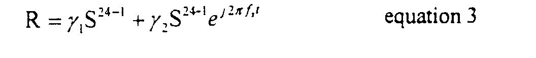
- Mobile-station 26 receives signal R comprising ⁇ 1 S 24-1 + ⁇ 2 S 24-2 .
- Distortion factor coefficient ⁇ eq can be estimated using pilot signals and used, along with equation 3b, to obtain estimates of signal s 1 and/or s 2 .
- PSTD improves performance (relative to when no transmit diversity technique is used) by making the received signal strength statistics associated with a slow fading channel at the receiver look like those associated with a fast fading channel.
- AWGN additive white gaussan noise
- the present invention is a method and apparatus of transmit diversity that is backward compatible and does not significantly degrade performance in additive white guassan noise (AWGN) conditions using a transmission architecture that incorporates a form of phase sweep transmit diversity (PSTD) referred to herein as biased PSTD.
- Biased PSTD involves transmitting a signal and a frequency swept version of the same signal over diversity antennas at different power levels. By transmitting the two signals at different power levels, the depths of nulls normally seen in AWGN conditions when PSTD is utilized is reduced and performance degradation in AWGN conditions is mitigated.
- FIG. 3 depicts a base station 30 employing code division multiple access (CDMA) and a form of phase sweep transmit diversity (PSTD) referred to herein as biased PSTD in accordance with the present invention.
- Biased PSTD involves transmitting a signal and a frequency swept version of the same signal over diversity antennas at different power levels to reduce the depths of nulls.
- biased PSTD is backwards compatible from the perspective of mobile-stations and does not degrade performance as much as PSTD in additive white gaussan noise (AWGN) conditions.
- AWGN additive white gaussan noise
- Base station 30 provides wireless communication services to mobile-stations, not shown, in its associated geographical coverage area or cell, wherein the cell is divided into three sectors ⁇ , ⁇ , ⁇ .
- Base station 30 includes a transmission architecture that biased PSTD, as will be described herein.
- Base station 30 comprises a processor 32, a splitter 34, multipliers 36, 38, amplifiers 44, 46, and a pair of diversity antennas 48, 50.
- base station 30 also includes configurations of splitters, multipliers, amplifiers and antennas for sectors ⁇ , ⁇ that are identical to those for sector ⁇ . For simplicity sake, the configurations for sectors ⁇ , ⁇ are not shown. Additionally, for discussion purposes, it is assumed that signals S k are intended for mobile-stations k located in sector ⁇ and, thus, the present invention will be described with reference to signals S k being processed for transmission over sector ⁇ .
- Processor 32 includes software for processing signals S k in accordance with well-known CDMA techniques to produce an output signal S k -1 . Note that, in another embodiment. processor 32 is operable to process signals S k in accordance with a multiple access technique other than CDMA, such as time or frequency division multiple access.
- Signal S k -1 is split by splitter 34 into signals S k -1 (a), S k -1 (b) and processed along paths A and B, respectively, by multipliers 36, 38, and amplifiers 44, 46 in accordance with bias PSTD techniques, wherein signal S k -1 (a) is identical to signal S k -1 (b) in terms of data.
- signal S k -1 is unevenly power split by splitter 34 such that the power level of signal S k -1 (a) is higher than the power level of signal S k -1 (b).
- signal S k -1 is power split such that signal S k -1 (a) gets 2/3 of signal S k -1 's power and signal S k -1 (b) gets 1/3 of signal S k -1 's power.
- signal S k -1 is unevenly power split by splitter 34 such that the power level of signal S k -1 (b) is higher than the power level of signal S k -1 (a), or signal S k -1 is evenly power split into signals S k -1 (a), S k -1 (b).
- the amounts of gain A 44 , A 46 are equal.
- signal S k -1 is split by splitter 34 such that the power level of signal S k -1 (a) is higher than the power level of signal S k- 1 (b), or vice-versa, so that differences in power level between signals S 44 and S 46 are not as large compared to an even power split of signal S k -1 .
- the amounts of gain A 44 , A 46 are different and related to how splitter 34 power splits signal S k -1 .
- the amount of gain A 44 , A 46 applied to signals S 36 , S 38 should be an amount that would cause the power levels of signals S 44 and S 46 to be approximately equal.
- power levels are "approximately equal" when the power levels are within 10% of each other.
- the signal, e.g., S 36 or S 38 associated with a greater power level is amplified more than the other signal.
- signal s ⁇ -1 and/or signals S 36 , S 40 are not biased or unevenly split or amplified, STS performance will degrade because signal S 44 will be transmitted at approximately 1/3 of the power at which signal S 46 will be transmitted.
- biasing or unevenly splitting signal s ⁇ -1 and/or biasing or unevenly amplifying signals S 36 , S 40 mitigates this degradation to STS performance relative to the case where neither signal s ⁇ -1 nor signals S 36 , S 40 are biased or unevenly split or amplified.
Abstract
Disclosed is a method and apparatus of transmit diversity that is backward
compatible and does not significantly degrade performance in additive white guassan noise
(AWGN) conditions using a transmission architecture that incorporates a form of phase sweep
transmit diversity (PSTD) referred to herein as biased PSTD. Biased PSTD involves transmitting a
signal and a frequency swept version of the same signal over diversity antennas at different power
levels. By transmitting the two signals at different power levels, the depths of nulls normally seen
in AWGN conditions when PSTD is utilized is reduced and performance degradation in AWGN
conditions is mitigated.
Description
- Performance of wireless communication systems is directly related to signal strength statistics of received signals. Third generation wireless communication systems utilize transmit diversity techniques for downlink transmissions (i.e., communication link from a base station to a mobile-station) in order to improve received signal strength statistics and, thus, performance. Two such transmit diversity techniques are space time spreading (STS) and phase sweep transmit diversity (PSTD).
- FIG. 1 depicts a wireless communication system 10 employing STS. Wireless communication system 10 comprises at least one base station 12 having two antenna elements 14-1 and 14-2, wherein antenna elements 14-1 and 14-2 are spaced far apart for achieving transmit diversity. Base station 12 receives a signal S for transmitting to mobile-station 16. Signal S is alternately divided into signals se and so , wherein signal se comprises even data bits and signal so comprises odd data bits. Signals se and so are processed to produce signals S14-1 and S14-2. Specifically, se is multiplied with Walsh code w 1 to produce signal sew 1; a conjugate of signal so is multiplied with Walsh code w 2 to produce signal so*w 2; signal so is multiplied with Walsh code w 1 to produce sow 1; and a conjugate of signal se is multiplied with Walsh code w 2 to produce se*w 2. Signal s ew 1 is added to signal so*w 2 to produce signal S14-1 (i.e., S14-1=sew 1+so *w 2) and signal se*w 2 is subtracted from signal sow 1 to produce signal S14-2 (i.e., S14-2=sow 1-se *w 2). Signals S14-1 and S14-2 are transmitted at substantially equal or identical power levels over antenna elements 14-1 and 14-2, respectively. For purposes of this application, power levels are "substantially equal" or "identical" when the power levels are within 1% of each other.
- Mobile-station 16 receives signal R comprising γ1(S14-2)+γ2(S14-2), wherein γ1 and γ2 are distortion factor coefficients associated with the transmission of signals S14-1 and S14-2 from antenna elements 14-1 and 14-2 to mobile-station 16, respectively. Distortion factor coefficients γ1 and γ2 can be estimated using pilot signals, as is well-known in the art. Mobile-station 16 decodes signal R with Walsh codes w 1 and w 2 to respectively produce outputs:
- However, STS is a transmit diversity technique that is not backward compatible from the perspective of the mobile-station. That is, mobile-station 16 is required to have the necessary hardware and/or software to decode signal R. Mobile-stations without such hardware and/or software, such as pre-third generation mobile-stations, would be incapable of decoding signal R.
- By contrast, phase sweep transmit diversity (PSTD) is backward compatible from the perspective of the mobile-station. FIG. 2 depicts a wireless communication system 20 employing PSTD. Wireless communication system 20 comprises at least one base station 22 having two antenna elements 24-1 and 24-2, wherein antenna elements 24-1 and 24-2 are spaced far apart for achieving transmit diversity. Base station 22 receives a signal S for transmitting to mobile-station 26. Signal S is evenly power split into signals s 1 and s 2 and processed to produce signals S24-1 and S24-2, where s 1=s 2. Specifically, signal s 1 is multiplied by Walsh code wk to produce S24-1=s 1 wk , where k represents a particular user or mobile-station. Signal s 2 is multiplied by Walsh code wk and a phase sweep frequency signalto produce S24-2, i.e.,

 where fs is a phase sweep frequency and t is time. Signals S24-1 and S24-2 are transmitted at substantially equal power levels over antenna elements 24-1 and 24-2, respectively. Note that the phase sweep signal
 is being represented in complex baseband notation, i.e.,
 It should be understood that the phase sweep signal may also be applied at an intermediate frequency or a radio frequency.
- Mobile-station 26 receives signal R comprising γ1S24-1+γ2S24-2. Simplifying the equation for R results in

- In slow fading channel conditions, PSTD improves performance (relative to when no transmit diversity technique is used) by making the received signal strength statistics associated with a slow fading channel at the receiver look like those associated with a fast fading channel. However, in additive white gaussan noise (AWGN) conditions, PSTD can significantly degrade performance. Accordingly, there exists a need for a transmit diversity technique that is backward compatible without significantly degrading performance in AGWN conditions.
- The present invention is a method and apparatus of transmit diversity that is backward compatible and does not significantly degrade performance in additive white guassan noise (AWGN) conditions using a transmission architecture that incorporates a form of phase sweep transmit diversity (PSTD) referred to herein as biased PSTD. Biased PSTD involves transmitting a signal and a frequency swept version of the same signal over diversity antennas at different power levels. By transmitting the two signals at different power levels, the depths of nulls normally seen in AWGN conditions when PSTD is utilized is reduced and performance degradation in AWGN conditions is mitigated.
- The features, aspects, and advantages of the present invention will become better understood with regard to the following description, appended claims, and accompanying drawings where
- FIG. 1 depicts a wireless communication system employing space time spreading techniques in accordance with the prior art;
- FIG. 2 depicts a wireless communication system employing phase sweep transmit diversity in accordance with the prior art; and
- FIG. 3 depicts a base station employing code division multiple access (CDMA) and a form of phase sweep transmit diversity (PSTD) referred to herein as biased PSTD in accordance with the present invention.
-
- FIG. 3 depicts a base station 30 employing code division multiple access (CDMA) and a form of phase sweep transmit diversity (PSTD) referred to herein as biased PSTD in accordance with the present invention. Biased PSTD involves transmitting a signal and a frequency swept version of the same signal over diversity antennas at different power levels to reduce the depths of nulls. Advantageously, biased PSTD is backwards compatible from the perspective of mobile-stations and does not degrade performance as much as PSTD in additive white gaussan noise (AWGN) conditions. CDMA is well-known in the art.
- Base station 30 provides wireless communication services to mobile-stations, not shown, in its associated geographical coverage area or cell, wherein the cell is divided into three sectors α, β, γ. Base station 30 includes a transmission architecture that biased PSTD, as will be described herein.
- Base station 30 comprises a processor 32, a splitter 34, multipliers 36, 38, amplifiers 44, 46, and a pair of diversity antennas 48, 50. Note that base station 30 also includes configurations of splitters, multipliers, amplifiers and antennas for sectors β, γ that are identical to those for sector α. For simplicity sake, the configurations for sectors β, γ are not shown. Additionally, for discussion purposes, it is assumed that signals S k are intended for mobile-stations k located in sector α and, thus, the present invention will be described with reference to signals S k being processed for transmission over sector α.
- Processor 32 includes software for processing signals S k in accordance with well-known CDMA techniques to produce an output signal S k -1. Note that, in another embodiment. processor 32 is operable to process signals S k in accordance with a multiple access technique other than CDMA, such as time or frequency division multiple access.
- Signal S k -1 is split by splitter 34 into signals S k -1(a), S k -1(b) and processed along paths A and B, respectively, by multipliers 36, 38, and amplifiers 44, 46 in accordance with bias PSTD techniques, wherein signal S k -1(a) is identical to signal S k -1(b) in terms of data. In one embodiment, signal S k -1 is unevenly power split by splitter 34 such that the power level of signal S k -1(a) is higher than the power level of signal S k -1(b). For example, signal S k -1 is power split such that signal S k -1(a) gets 5/8 of signal S k -1's power and signal S k -1(b) gets 3/8 of signal S k -1's power, i.e., S k -1(a)=are provided as inputs into multiplier 36 to produce signal S36, where S36=S k -1 (a)eJ 2 πf c t , eJ 2 πf c t = cos(2πf c t)+jsin(2πf c t), f c represents a carrier frequency and t represents time.

- Signal S k -1(b), phase sweep frequency signal eJΘ 5( t ) and carrier signal eJ 2π f c t are provided as inputs into multiplier 38 where signal S k -1(b)is frequency phase swept with signal eJΘ ,( t ) and modulated onto carrier signal eJ 2 πfct to produce signal S38 =S k -1(b)eJ 2 πfcteJΘ 5( t ), whereinand fs represents a phase sweep frequency.

- Signals S36, S38 are amplified by amplifiers 44, 46 to produce signals S44 and S46 for transmission over antennas 48, 50, respectively, where signal S44=A44 S k -1(a)ej 2 πfct , S46=A46S k -1(b)eJ 2π fcteJΘ5 ( t ), A44 represents the amount of gain associated with amplifier 44 and A46 represents the amount of gain associated with amplifier 46.
- In one embodiment, the amounts of gain A44, A46 are equal. In this embodiment, signal S k -1 is split by splitter 34 such that the power level of signal S k -1(a) is higher than the power level of signal S k- 1(b), or vice-versa, so that differences in power level between signals S44 and S46 are not as large compared to an even power split of signal S k -1.
- In another embodiment, the amounts of gain A44, A46 are different and related to how splitter 34 power splits signal S k -1. For example, the amount of gain A44, A46 applied to signals S36, S38 should be an amount that would cause the power levels of signals S44 and S46 to be approximately equal. For purposes of this application, power levels are "approximately equal" when the power levels are within 10% of each other. In another example, the signal, e.g., S36 or S38 associated with a greater power level is amplified more than the other signal.
- In the case where signal sα-1 and/or signals S36, S40 are not biased or unevenly split or amplified, STS performance will degrade because signal S44 will be transmitted at approximately 1/3 of the power at which signal S46 will be transmitted. Advantageously, biasing or unevenly splitting signal sα-1 and/or biasing or unevenly amplifying signals S36, S40 mitigates this degradation to STS performance relative to the case where neither signal sα-1 nor signals S36, S40 are biased or unevenly split or amplified.
- Although the present invention has been described in considerable detail with reference to certain embodiments, other versions are possible. Therefore, the scope of the present invention should not be limited to the description of the embodiments contained herein.
Claims (10)
- A method of signal transmission comprising the steps of:splitting a signal s1 into signals s1(a) and s1(b), wherein the signal s1 is split unevenly such that the signal s1(a) has an associated power level greater than a power level associated with the signal s1(b); andphase sweeping the signal s1(b) using a phase sweep frequency signal to produce a phase swept signal s1(b).
- The method of claim 1 comprising the additional steps of:amplifying the signal s1(a) to produce an amplified signal s1(a); andamplifying the phase swept signal s1(b) to produce an amplified phase swept signal s1(b).
- The method of claim 2, wherein power levels associated with the amplified signal s1(a) and the amplified phase swept signal s1(b) are approximately equal.
- The method of claim 2, wherein the signal s1(a) and phase swept signal s1(b) are amplified an equal amount.
- The method of claim 2, wherein the signal s1(a) is amplified an amount greater than an amount phase swept signal s1(b) is amplified.
- A method of signal transmission comprising the steps of:splitting a signal s1 into signals s1(a) and s1(b), wherein the signal s1 is split unevenly such that the signal s1(a) has an associated power level greater than a power level associated with the signal s1(b); andphase sweeping the signal s1(a) using a phase sweep frequency signal to produce a phase swept signal s1(b).
- The method of claim 6 comprising the additional steps of:amplifying the signal s1(b) to produce an amplified signal s1(b); andamplifying the phase swept signal s1(a) to produce an amplified phase swept signal s1(a).
- The method of claim 7, wherein power levels associated with the amplified signal s1(b) and the amplified phase swept signal s1(a) are approximately equal.
- The method of claim 7, wherein the signal s1(b) and phase swept signal s1(a) are amplified an equal amount.
- The method of claim 7, wherein the signal s1(b) is amplified an amount greater than an amount phase swept signal s1(a) is amplified.
Applications Claiming Priority (2)
| Application Number | Priority Date | Filing Date | Title |
|---|---|---|---|
| US09/918,393 US7035599B2 (en) | 2001-07-30 | 2001-07-30 | Biased phase sweep transmit diversity |
| US918393 | 2001-07-30 |
Publications (1)
| Publication Number | Publication Date |
|---|---|
| EP1282243A1 true EP1282243A1 (en) | 2003-02-05 |
Family
ID=25440301
Family Applications (1)
| Application Number | Title | Priority Date | Filing Date |
|---|---|---|---|
| EP02250952A Withdrawn EP1282243A1 (en) | 2001-07-30 | 2002-02-12 | Biased phase sweep transmit diversity |
Country Status (2)
| Country | Link |
|---|---|
| US (1) | US7035599B2 (en) |
| EP (1) | EP1282243A1 (en) |
Families Citing this family (2)
| Publication number | Priority date | Publication date | Assignee | Title |
|---|---|---|---|---|
| US20060172710A1 (en) * | 2003-03-26 | 2006-08-03 | Celletra Ltd. | Phase sweeping methods for transmit diversity and diversity combining in bts sector extension and in wireless repeaters |
| US7860465B2 (en) | 2007-05-01 | 2010-12-28 | Research In Motion Limited | Apparatus, and associated method, for providing open loop diversity in a radio communication system |
Family Cites Families (5)
| Publication number | Priority date | Publication date | Assignee | Title |
|---|---|---|---|---|
| EP0622910B1 (en) * | 1993-04-29 | 2003-06-25 | Ericsson Inc. | Time diversity transmission system for the reduction of adjacent channel interference in mobile telephone systems |
| US6704370B1 (en) * | 1998-10-09 | 2004-03-09 | Nortel Networks Limited | Interleaving methodology and apparatus for CDMA |
| US6317411B1 (en) | 1999-02-22 | 2001-11-13 | Motorola, Inc. | Method and system for transmitting and receiving signals transmitted from an antenna array with transmit diversity techniques |
| US6594473B1 (en) * | 1999-05-28 | 2003-07-15 | Texas Instruments Incorporated | Wireless system with transmitter having multiple transmit antennas and combining open loop and closed loop transmit diversities |
| US6788661B1 (en) * | 1999-11-12 | 2004-09-07 | Nikia Networks Oy | Adaptive beam-time coding method and apparatus |
-
2001
- 2001-07-30 US US09/918,393 patent/US7035599B2/en not_active Expired - Fee Related
-
2002
- 2002-02-12 EP EP02250952A patent/EP1282243A1/en not_active Withdrawn
Non-Patent Citations (4)
| Title |
|---|
| CHHEDA A: "ON THE FORWARD LINK CAPACITY OF A CDMA2000-1X SYSTEM WITH TRANSMIT DIVERSITY", VTC 2000-FALL. IEEE VTS 52ND. VEHICULAR TECHNOLOGY CONFERENCE. BOSTON, MA, SEPT. 24 - 28, 2000, IEEE VEHICULAR TECHNOLGY CONFERENCE, NEW YORK, NY: IEEE, US, vol. 2 OF 6. CONF. 52, 24 September 2000 (2000-09-24), pages 618 - 623, XP001017320, ISBN: 0-7803-6508-9 * |
| GUTIERREZ A ET AL: "AN INTRODUCTION TO PSTD FOR IS-95 AND CDMA2000", WCNC. IEEE WIRELESS COMMUNICATIONS AND NETWORKING CONFERENCE, XX, XX, 21 September 1999 (1999-09-21), pages 1358 - 1362, XP001084288 * |
| HIROIKE A ET AL: "COMBINED EFFECTS OF PHASE SWEEPING TRANSMITTER DIVERSITY AND CHANNEL CODING", IEEE TRANSACTIONS ON VEHICULAR TECHNOLOGY, IEEE INC. NEW YORK, US, vol. 41, no. 2, May 1992 (1992-05-01), pages 170 - 176, XP001084487, ISSN: 0018-9545 * |
| SU B D ET AL: "Phase sweeping transmitter diversity in mobile communications", VEHICULAR TECHNOLOGY CONFERENCE, 1996. MOBILE TECHNOLOGY FOR THE HUMAN RACE., IEEE 46TH ATLANTA, GA, USA 28 APRIL-1 MAY 1996, NEW YORK, NY, USA,IEEE, US, 28 April 1996 (1996-04-28), pages 131 - 135, XP010162362, ISBN: 0-7803-3157-5 * |
Also Published As
| Publication number | Publication date |
|---|---|
| US7035599B2 (en) | 2006-04-25 |
| US20030022641A1 (en) | 2003-01-30 |
Similar Documents
| Publication | Publication Date | Title |
|---|---|---|
| EP1282242A1 (en) | Split shift phase sweep transmit diversity | |
| US6920314B2 (en) | Symmetric sweep phase sweep transmit diversity | |
| US6771689B2 (en) | Transmit diversity and reception equalization for radio links | |
| US6285861B1 (en) | Receiving station with interference signal suppression | |
| US6392988B1 (en) | Transmitter architecture employing space time spreading and orthogonal transmit diversity techniques | |
| US6470194B1 (en) | Base station with improved directivity using adaptive antenna array reception | |
| US7164725B2 (en) | Method and apparatus for antenna array beamforming | |
| US20100149039A1 (en) | Multi-antenna beam-forming system for transmitting constant envelope signals decomposed from a variable envelope signal | |
| EP1949558B1 (en) | Method and system for multiple antenna communications, related apparatus and corresponding computer program product | |
| EP1780902B1 (en) | Receiving station with interference signal suppression | |
| US20030013468A1 (en) | Radio communication system | |
| JPH06169273A (en) | Radio receiver, transmitter and repeater for execution of diversity | |
| KR20050098028A (en) | Method and system for improving communication | |
| KR20010032335A (en) | Method and apparatus for receiving radio signals | |
| CA2326865C (en) | An apparatus and method of enhancing transmit diversity | |
| EP1508979B1 (en) | Apparatus and method for receiving signal in mobile communication system using adaptive antenna array scheme | |
| US6232927B1 (en) | Array antenna apparatus for use in spread spectrum communications with a particular interval between antenna elements | |
| US7042955B2 (en) | Space time spreading and phase sweep transmit diversity | |
| US7319822B2 (en) | System and method of space-time equalization to mitigate effects of fading and scintillation for wireless communication | |
| EP1282243A1 (en) | Biased phase sweep transmit diversity | |
| JP2022527226A (en) | Interference elimination using a circularly polarized antenna | |
| WO1996008088A1 (en) | Diversity receiver with combiner for equalization and diversity transmitter with splitter and delay | |
| CA2392668C (en) | Biased phase-sweep transmit diversity | |
| US20070064773A1 (en) | Multi-carrier spread spectrum using non-linear modification of sub-carrier bands | |
| KR20030090173A (en) | Space-time transmitter having characteristic of time delay |
Legal Events
| Date | Code | Title | Description |
|---|---|---|---|
| PUAI | Public reference made under article 153(3) epc to a published international application that has entered the european phase |
Free format text: ORIGINAL CODE: 0009012 |
|
| 17P | Request for examination filed |
Effective date: 20020226 |
|
| AK | Designated contracting states |
Designated state(s): AT BE CH CY DE DK ES FI FR GB GR IE IT LI LU MC NL PT SE TR |
|
| AX | Request for extension of the european patent |
Extension state: AL LT LV MK RO SI |
|
| GRAP | Despatch of communication of intention to grant a patent |
Free format text: ORIGINAL CODE: EPIDOSNIGR1 |
|
| AKX | Designation fees paid |
Designated state(s): DE FR |
|
| STAA | Information on the status of an ep patent application or granted ep patent |
Free format text: STATUS: THE APPLICATION IS DEEMED TO BE WITHDRAWN |
|
| 18D | Application deemed to be withdrawn |
Effective date: 20031202 |