EP1281514A2 - Lithographic process using reaction of o-quinodimethane - Google Patents
Lithographic process using reaction of o-quinodimethane Download PDFInfo
- Publication number
- EP1281514A2 EP1281514A2 EP02015574A EP02015574A EP1281514A2 EP 1281514 A2 EP1281514 A2 EP 1281514A2 EP 02015574 A EP02015574 A EP 02015574A EP 02015574 A EP02015574 A EP 02015574A EP 1281514 A2 EP1281514 A2 EP 1281514A2
- Authority
- EP
- European Patent Office
- Prior art keywords
- image
- structures
- plate
- forming layer
- polymer
- Prior art date
- Legal status (The legal status is an assumption and is not a legal conclusion. Google has not performed a legal analysis and makes no representation as to the accuracy of the status listed.)
- Granted
Links
- 238000000034 method Methods 0.000 title claims abstract description 72
- XURVRZSODRHRNK-UHFFFAOYSA-N o-quinodimethane Chemical compound C=C1C=CC=CC1=C XURVRZSODRHRNK-UHFFFAOYSA-N 0.000 title claims abstract description 59
- 238000006243 chemical reaction Methods 0.000 title abstract description 11
- 238000007639 printing Methods 0.000 claims abstract description 126
- 150000001875 compounds Chemical class 0.000 claims abstract description 82
- 229920000642 polymer Polymers 0.000 claims abstract description 68
- 239000002243 precursor Chemical group 0.000 claims abstract description 45
- 238000010438 heat treatment Methods 0.000 claims abstract description 15
- 229920001600 hydrophobic polymer Polymers 0.000 claims description 59
- 239000002245 particle Substances 0.000 claims description 53
- 229920001477 hydrophilic polymer Polymers 0.000 claims description 33
- XLYOFNOQVPJJNP-UHFFFAOYSA-N water Substances O XLYOFNOQVPJJNP-UHFFFAOYSA-N 0.000 claims description 31
- UMIVXZPTRXBADB-UHFFFAOYSA-N benzocyclobutene Chemical group C1=CC=C2CCC2=C1 UMIVXZPTRXBADB-UHFFFAOYSA-N 0.000 claims description 18
- 239000003795 chemical substances by application Substances 0.000 claims description 15
- 239000000243 solution Substances 0.000 description 65
- 238000011282 treatment Methods 0.000 description 61
- -1 amino, ammonio, hydroxyl Chemical group 0.000 description 53
- ZWEHNKRNPOVVGH-UHFFFAOYSA-N 2-Butanone Chemical compound CCC(C)=O ZWEHNKRNPOVVGH-UHFFFAOYSA-N 0.000 description 51
- 229920001577 copolymer Polymers 0.000 description 47
- 125000004185 ester group Chemical group 0.000 description 44
- 239000011248 coating agent Substances 0.000 description 43
- 238000000576 coating method Methods 0.000 description 43
- 125000001931 aliphatic group Chemical group 0.000 description 41
- 229910052782 aluminium Inorganic materials 0.000 description 40
- XAGFODPZIPBFFR-UHFFFAOYSA-N aluminium Chemical compound [Al] XAGFODPZIPBFFR-UHFFFAOYSA-N 0.000 description 39
- 125000001424 substituent group Chemical group 0.000 description 39
- 125000003118 aryl group Chemical group 0.000 description 37
- 125000000623 heterocyclic group Chemical group 0.000 description 37
- 239000000975 dye Substances 0.000 description 31
- 239000004094 surface-active agent Substances 0.000 description 30
- 230000015572 biosynthetic process Effects 0.000 description 29
- XEKOWRVHYACXOJ-UHFFFAOYSA-N Ethyl acetate Chemical compound CCOC(C)=O XEKOWRVHYACXOJ-UHFFFAOYSA-N 0.000 description 27
- 125000000020 sulfo group Chemical group O=S(=O)([*])O[H] 0.000 description 24
- 239000006185 dispersion Substances 0.000 description 23
- 238000003384 imaging method Methods 0.000 description 23
- 239000010419 fine particle Substances 0.000 description 22
- 125000001476 phosphono group Chemical group [H]OP(*)(=O)O[H] 0.000 description 22
- 239000007864 aqueous solution Substances 0.000 description 21
- 229910052751 metal Inorganic materials 0.000 description 20
- 239000002184 metal Substances 0.000 description 20
- 239000003094 microcapsule Substances 0.000 description 20
- 150000003839 salts Chemical class 0.000 description 18
- 125000004432 carbon atom Chemical group C* 0.000 description 17
- 125000003178 carboxy group Chemical group [H]OC(*)=O 0.000 description 17
- 239000000049 pigment Substances 0.000 description 17
- 238000007865 diluting Methods 0.000 description 16
- 125000005843 halogen group Chemical group 0.000 description 15
- 238000002360 preparation method Methods 0.000 description 15
- 239000000126 substance Substances 0.000 description 15
- QAOWNCQODCNURD-UHFFFAOYSA-N Sulfuric acid Chemical compound OS(O)(=O)=O QAOWNCQODCNURD-UHFFFAOYSA-N 0.000 description 14
- 229910052794 bromium Inorganic materials 0.000 description 13
- 229910052801 chlorine Inorganic materials 0.000 description 13
- 229910052731 fluorine Inorganic materials 0.000 description 13
- 229910052740 iodine Inorganic materials 0.000 description 13
- 239000000203 mixture Substances 0.000 description 13
- 239000002904 solvent Substances 0.000 description 13
- OKKJLVBELUTLKV-UHFFFAOYSA-N Methanol Chemical compound OC OKKJLVBELUTLKV-UHFFFAOYSA-N 0.000 description 12
- 239000006229 carbon black Substances 0.000 description 12
- 238000003786 synthesis reaction Methods 0.000 description 12
- 230000002209 hydrophobic effect Effects 0.000 description 11
- 230000002378 acidificating effect Effects 0.000 description 10
- 125000002947 alkylene group Chemical group 0.000 description 10
- 150000002739 metals Chemical class 0.000 description 10
- 239000004372 Polyvinyl alcohol Substances 0.000 description 9
- 239000001257 hydrogen Substances 0.000 description 9
- 229910052739 hydrogen Inorganic materials 0.000 description 9
- 239000003921 oil Substances 0.000 description 9
- 238000006116 polymerization reaction Methods 0.000 description 9
- 229920002451 polyvinyl alcohol Polymers 0.000 description 9
- 235000019422 polyvinyl alcohol Nutrition 0.000 description 9
- 235000010724 Wisteria floribunda Nutrition 0.000 description 8
- 238000001816 cooling Methods 0.000 description 8
- 238000011156 evaluation Methods 0.000 description 8
- 239000000178 monomer Substances 0.000 description 8
- 230000003647 oxidation Effects 0.000 description 8
- 238000007254 oxidation reaction Methods 0.000 description 8
- 239000004065 semiconductor Substances 0.000 description 8
- 239000007787 solid Substances 0.000 description 8
- ARXJGSRGQADJSQ-UHFFFAOYSA-N 1-methoxypropan-2-ol Chemical compound COCC(C)O ARXJGSRGQADJSQ-UHFFFAOYSA-N 0.000 description 7
- 239000004215 Carbon black (E152) Substances 0.000 description 7
- YCKRFDGAMUMZLT-UHFFFAOYSA-N Fluorine atom Chemical compound [F] YCKRFDGAMUMZLT-UHFFFAOYSA-N 0.000 description 7
- 125000000217 alkyl group Chemical group 0.000 description 7
- 239000003086 colorant Substances 0.000 description 7
- 239000000839 emulsion Substances 0.000 description 7
- 239000011737 fluorine Substances 0.000 description 7
- 229930195733 hydrocarbon Natural products 0.000 description 7
- 150000002430 hydrocarbons Chemical class 0.000 description 7
- 125000004435 hydrogen atom Chemical group [H]* 0.000 description 7
- XEEYBQQBJWHFJM-UHFFFAOYSA-N iron Substances [Fe] XEEYBQQBJWHFJM-UHFFFAOYSA-N 0.000 description 7
- 125000001434 methanylylidene group Chemical group [H]C#[*] 0.000 description 7
- 238000005698 Diels-Alder reaction Methods 0.000 description 6
- LFQSCWFLJHTTHZ-UHFFFAOYSA-N Ethanol Chemical compound CCO LFQSCWFLJHTTHZ-UHFFFAOYSA-N 0.000 description 6
- VEXZGXHMUGYJMC-UHFFFAOYSA-N Hydrochloric acid Chemical compound Cl VEXZGXHMUGYJMC-UHFFFAOYSA-N 0.000 description 6
- ZMXDDKWLCZADIW-UHFFFAOYSA-N N,N-Dimethylformamide Chemical compound CN(C)C=O ZMXDDKWLCZADIW-UHFFFAOYSA-N 0.000 description 6
- ZMANZCXQSJIPKH-UHFFFAOYSA-N Triethylamine Chemical compound CCN(CC)CC ZMANZCXQSJIPKH-UHFFFAOYSA-N 0.000 description 6
- 125000000732 arylene group Chemical group 0.000 description 6
- 229920001519 homopolymer Polymers 0.000 description 6
- 230000005660 hydrophilic surface Effects 0.000 description 6
- 125000005647 linker group Chemical group 0.000 description 6
- 239000000155 melt Substances 0.000 description 6
- 239000000123 paper Substances 0.000 description 6
- 229920002635 polyurethane Polymers 0.000 description 6
- 239000004814 polyurethane Substances 0.000 description 6
- 229920002689 polyvinyl acetate Polymers 0.000 description 6
- 239000011118 polyvinyl acetate Substances 0.000 description 6
- 229920001059 synthetic polymer Polymers 0.000 description 6
- YTTFFPATQICAQN-UHFFFAOYSA-N 2-methoxypropan-1-ol Chemical compound COC(C)CO YTTFFPATQICAQN-UHFFFAOYSA-N 0.000 description 5
- LYCAIKOWRPUZTN-UHFFFAOYSA-N Ethylene glycol Chemical compound OCCO LYCAIKOWRPUZTN-UHFFFAOYSA-N 0.000 description 5
- BPQQTUXANYXVAA-UHFFFAOYSA-N Orthosilicate Chemical compound [O-][Si]([O-])([O-])[O-] BPQQTUXANYXVAA-UHFFFAOYSA-N 0.000 description 5
- 229910045601 alloy Inorganic materials 0.000 description 5
- 239000000956 alloy Substances 0.000 description 5
- 125000000129 anionic group Chemical group 0.000 description 5
- 229910052802 copper Inorganic materials 0.000 description 5
- 238000005530 etching Methods 0.000 description 5
- 125000000962 organic group Chemical group 0.000 description 5
- 229910052709 silver Inorganic materials 0.000 description 5
- 230000003746 surface roughness Effects 0.000 description 5
- 238000004381 surface treatment Methods 0.000 description 5
- 239000010936 titanium Substances 0.000 description 5
- XQUPVDVFXZDTLT-UHFFFAOYSA-N 1-[4-[[4-(2,5-dioxopyrrol-1-yl)phenyl]methyl]phenyl]pyrrole-2,5-dione Chemical compound O=C1C=CC(=O)N1C(C=C1)=CC=C1CC1=CC=C(N2C(C=CC2=O)=O)C=C1 XQUPVDVFXZDTLT-UHFFFAOYSA-N 0.000 description 4
- JDTUPLBMGDDPJS-UHFFFAOYSA-N 2-methoxy-2-phenylethanol Chemical compound COC(CO)C1=CC=CC=C1 JDTUPLBMGDDPJS-UHFFFAOYSA-N 0.000 description 4
- IJGRMHOSHXDMSA-UHFFFAOYSA-N Atomic nitrogen Chemical compound N#N IJGRMHOSHXDMSA-UHFFFAOYSA-N 0.000 description 4
- 229920002134 Carboxymethyl cellulose Polymers 0.000 description 4
- 239000004375 Dextrin Substances 0.000 description 4
- 229920001353 Dextrin Polymers 0.000 description 4
- 239000004952 Polyamide Substances 0.000 description 4
- 229920002396 Polyurea Polymers 0.000 description 4
- VYPSYNLAJGMNEJ-UHFFFAOYSA-N Silicium dioxide Chemical compound O=[Si]=O VYPSYNLAJGMNEJ-UHFFFAOYSA-N 0.000 description 4
- WYURNTSHIVDZCO-UHFFFAOYSA-N Tetrahydrofuran Chemical compound C1CCOC1 WYURNTSHIVDZCO-UHFFFAOYSA-N 0.000 description 4
- XSQUKJJJFZCRTK-UHFFFAOYSA-N Urea Chemical compound NC(N)=O XSQUKJJJFZCRTK-UHFFFAOYSA-N 0.000 description 4
- 239000002253 acid Substances 0.000 description 4
- 239000003513 alkali Substances 0.000 description 4
- ANBBXQWFNXMHLD-UHFFFAOYSA-N aluminum;sodium;oxygen(2-) Chemical compound [O-2].[O-2].[Na+].[Al+3] ANBBXQWFNXMHLD-UHFFFAOYSA-N 0.000 description 4
- 150000001412 amines Chemical class 0.000 description 4
- 229910052787 antimony Inorganic materials 0.000 description 4
- UCMIRNVEIXFBKS-UHFFFAOYSA-N beta-alanine Chemical compound NCCC(O)=O UCMIRNVEIXFBKS-UHFFFAOYSA-N 0.000 description 4
- 239000011230 binding agent Substances 0.000 description 4
- 235000010948 carboxy methyl cellulose Nutrition 0.000 description 4
- 125000004122 cyclic group Chemical group 0.000 description 4
- 235000019425 dextrin Nutrition 0.000 description 4
- 238000006471 dimerization reaction Methods 0.000 description 4
- 238000007720 emulsion polymerization reaction Methods 0.000 description 4
- LZCLXQDLBQLTDK-UHFFFAOYSA-N ethyl 2-hydroxypropanoate Chemical compound CCOC(=O)C(C)O LZCLXQDLBQLTDK-UHFFFAOYSA-N 0.000 description 4
- 229910052737 gold Inorganic materials 0.000 description 4
- 238000000227 grinding Methods 0.000 description 4
- 229910052742 iron Inorganic materials 0.000 description 4
- 238000000465 moulding Methods 0.000 description 4
- 229920000620 organic polymer Polymers 0.000 description 4
- 125000004043 oxo group Chemical group O=* 0.000 description 4
- 125000000843 phenylene group Chemical group C1(=C(C=CC=C1)*)* 0.000 description 4
- 229920002647 polyamide Polymers 0.000 description 4
- 229920000728 polyester Polymers 0.000 description 4
- 229920005989 resin Polymers 0.000 description 4
- 239000011347 resin Substances 0.000 description 4
- 239000012487 rinsing solution Substances 0.000 description 4
- 239000004576 sand Substances 0.000 description 4
- 230000035945 sensitivity Effects 0.000 description 4
- 229910001388 sodium aluminate Inorganic materials 0.000 description 4
- 125000000446 sulfanediyl group Chemical group *S* 0.000 description 4
- XRXZXWWBZJOKEF-UHFFFAOYSA-N 2-(7-bicyclo[4.2.0]octa-1,3,5-trienyloxy)ethanol Chemical compound C1=CC=C2C(OCCO)CC2=C1 XRXZXWWBZJOKEF-UHFFFAOYSA-N 0.000 description 3
- NIXOWILDQLNWCW-UHFFFAOYSA-M Acrylate Chemical compound [O-]C(=O)C=C NIXOWILDQLNWCW-UHFFFAOYSA-M 0.000 description 3
- WSFSSNUMVMOOMR-UHFFFAOYSA-N Formaldehyde Chemical compound O=C WSFSSNUMVMOOMR-UHFFFAOYSA-N 0.000 description 3
- PEDCQBHIVMGVHV-UHFFFAOYSA-N Glycerine Chemical compound OCC(O)CO PEDCQBHIVMGVHV-UHFFFAOYSA-N 0.000 description 3
- 229920000084 Gum arabic Polymers 0.000 description 3
- GRYLNZFGIOXLOG-UHFFFAOYSA-N Nitric acid Chemical compound O[N+]([O-])=O GRYLNZFGIOXLOG-UHFFFAOYSA-N 0.000 description 3
- MUBZPKHOEPUJKR-UHFFFAOYSA-N Oxalic acid Chemical compound OC(=O)C(O)=O MUBZPKHOEPUJKR-UHFFFAOYSA-N 0.000 description 3
- 239000004642 Polyimide Substances 0.000 description 3
- 239000004721 Polyphenylene oxide Substances 0.000 description 3
- KWYUFKZDYYNOTN-UHFFFAOYSA-M Potassium hydroxide Chemical compound [OH-].[K+] KWYUFKZDYYNOTN-UHFFFAOYSA-M 0.000 description 3
- 241000978776 Senegalia senegal Species 0.000 description 3
- 239000004115 Sodium Silicate Substances 0.000 description 3
- HEMHJVSKTPXQMS-UHFFFAOYSA-M Sodium hydroxide Chemical compound [OH-].[Na+] HEMHJVSKTPXQMS-UHFFFAOYSA-M 0.000 description 3
- YXFVVABEGXRONW-UHFFFAOYSA-N Toluene Chemical compound CC1=CC=CC=C1 YXFVVABEGXRONW-UHFFFAOYSA-N 0.000 description 3
- 238000005299 abrasion Methods 0.000 description 3
- 235000010489 acacia gum Nutrition 0.000 description 3
- 239000000205 acacia gum Substances 0.000 description 3
- 229910052783 alkali metal Inorganic materials 0.000 description 3
- 150000001340 alkali metals Chemical class 0.000 description 3
- QVGXLLKOCUKJST-UHFFFAOYSA-N atomic oxygen Chemical compound [O] QVGXLLKOCUKJST-UHFFFAOYSA-N 0.000 description 3
- 239000000987 azo dye Substances 0.000 description 3
- 239000011203 carbon fibre reinforced carbon Substances 0.000 description 3
- 150000001244 carboxylic acid anhydrides Chemical class 0.000 description 3
- 229910052804 chromium Inorganic materials 0.000 description 3
- 238000005516 engineering process Methods 0.000 description 3
- RTZKZFJDLAIYFH-UHFFFAOYSA-N ether Substances CCOCC RTZKZFJDLAIYFH-UHFFFAOYSA-N 0.000 description 3
- 229910052732 germanium Inorganic materials 0.000 description 3
- 239000012948 isocyanate Substances 0.000 description 3
- 239000000463 material Substances 0.000 description 3
- 229910017604 nitric acid Inorganic materials 0.000 description 3
- 229910052760 oxygen Inorganic materials 0.000 description 3
- 239000001301 oxygen Substances 0.000 description 3
- 229920000570 polyether Polymers 0.000 description 3
- 229920001721 polyimide Polymers 0.000 description 3
- 229920000098 polyolefin Polymers 0.000 description 3
- 125000002924 primary amino group Chemical group [H]N([H])* 0.000 description 3
- 229910052702 rhenium Inorganic materials 0.000 description 3
- NTHWMYGWWRZVTN-UHFFFAOYSA-N sodium silicate Chemical compound [Na+].[Na+].[O-][Si]([O-])=O NTHWMYGWWRZVTN-UHFFFAOYSA-N 0.000 description 3
- 229910052911 sodium silicate Inorganic materials 0.000 description 3
- 125000003003 spiro group Chemical group 0.000 description 3
- 229910052718 tin Inorganic materials 0.000 description 3
- 229910052719 titanium Inorganic materials 0.000 description 3
- BNGXYYYYKUGPPF-UHFFFAOYSA-M (3-methylphenyl)methyl-triphenylphosphanium;chloride Chemical compound [Cl-].CC1=CC=CC(C[P+](C=2C=CC=CC=2)(C=2C=CC=CC=2)C=2C=CC=CC=2)=C1 BNGXYYYYKUGPPF-UHFFFAOYSA-M 0.000 description 2
- QGKMIGUHVLGJBR-UHFFFAOYSA-M (4z)-1-(3-methylbutyl)-4-[[1-(3-methylbutyl)quinolin-1-ium-4-yl]methylidene]quinoline;iodide Chemical compound [I-].C12=CC=CC=C2N(CCC(C)C)C=CC1=CC1=CC=[N+](CCC(C)C)C2=CC=CC=C12 QGKMIGUHVLGJBR-UHFFFAOYSA-M 0.000 description 2
- MYWOJODOMFBVCB-UHFFFAOYSA-N 1,2,6-trimethylphenanthrene Chemical compound CC1=CC=C2C3=CC(C)=CC=C3C=CC2=C1C MYWOJODOMFBVCB-UHFFFAOYSA-N 0.000 description 2
- 125000001140 1,4-phenylene group Chemical group [H]C1=C([H])C([*:2])=C([H])C([H])=C1[*:1] 0.000 description 2
- XNWFRZJHXBZDAG-UHFFFAOYSA-N 2-METHOXYETHANOL Chemical compound COCCO XNWFRZJHXBZDAG-UHFFFAOYSA-N 0.000 description 2
- XLLIQLLCWZCATF-UHFFFAOYSA-N 2-methoxyethyl acetate Chemical compound COCCOC(C)=O XLLIQLLCWZCATF-UHFFFAOYSA-N 0.000 description 2
- LPEKGGXMPWTOCB-UHFFFAOYSA-N 8beta-(2,3-epoxy-2-methylbutyryloxy)-14-acetoxytithifolin Natural products COC(=O)C(C)O LPEKGGXMPWTOCB-UHFFFAOYSA-N 0.000 description 2
- KCXZNSGUUQJJTR-UHFFFAOYSA-N Di-n-hexyl phthalate Chemical compound CCCCCCOC(=O)C1=CC=CC=C1C(=O)OCCCCCC KCXZNSGUUQJJTR-UHFFFAOYSA-N 0.000 description 2
- IAZDPXIOMUYVGZ-UHFFFAOYSA-N Dimethylsulphoxide Chemical compound CS(C)=O IAZDPXIOMUYVGZ-UHFFFAOYSA-N 0.000 description 2
- DHMQDGOQFOQNFH-UHFFFAOYSA-N Glycine Chemical compound NCC(O)=O DHMQDGOQFOQNFH-UHFFFAOYSA-N 0.000 description 2
- UFHFLCQGNIYNRP-UHFFFAOYSA-N Hydrogen Chemical compound [H][H] UFHFLCQGNIYNRP-UHFFFAOYSA-N 0.000 description 2
- CERQOIWHTDAKMF-UHFFFAOYSA-M Methacrylate Chemical compound CC(=C)C([O-])=O CERQOIWHTDAKMF-UHFFFAOYSA-M 0.000 description 2
- 229920000881 Modified starch Polymers 0.000 description 2
- FXHOOIRPVKKKFG-UHFFFAOYSA-N N,N-Dimethylacetamide Chemical compound CN(C)C(C)=O FXHOOIRPVKKKFG-UHFFFAOYSA-N 0.000 description 2
- 229920002845 Poly(methacrylic acid) Polymers 0.000 description 2
- 239000002202 Polyethylene glycol Substances 0.000 description 2
- 229920002125 Sokalan® Polymers 0.000 description 2
- DKGAVHZHDRPRBM-UHFFFAOYSA-N Tert-Butanol Chemical compound CC(C)(C)O DKGAVHZHDRPRBM-UHFFFAOYSA-N 0.000 description 2
- ZFOZVQLOBQUTQQ-UHFFFAOYSA-N Tributyl citrate Chemical compound CCCCOC(=O)CC(O)(C(=O)OCCCC)CC(=O)OCCCC ZFOZVQLOBQUTQQ-UHFFFAOYSA-N 0.000 description 2
- MPIAGWXWVAHQBB-UHFFFAOYSA-N [3-prop-2-enoyloxy-2-[[3-prop-2-enoyloxy-2,2-bis(prop-2-enoyloxymethyl)propoxy]methyl]-2-(prop-2-enoyloxymethyl)propyl] prop-2-enoate Chemical compound C=CC(=O)OCC(COC(=O)C=C)(COC(=O)C=C)COCC(COC(=O)C=C)(COC(=O)C=C)COC(=O)C=C MPIAGWXWVAHQBB-UHFFFAOYSA-N 0.000 description 2
- 238000010521 absorption reaction Methods 0.000 description 2
- 238000010539 anionic addition polymerization reaction Methods 0.000 description 2
- 238000000137 annealing Methods 0.000 description 2
- 239000008346 aqueous phase Substances 0.000 description 2
- 239000011324 bead Substances 0.000 description 2
- AOJOEFVRHOZDFN-UHFFFAOYSA-N benzyl 2-methylprop-2-enoate Chemical compound CC(=C)C(=O)OCC1=CC=CC=C1 AOJOEFVRHOZDFN-UHFFFAOYSA-N 0.000 description 2
- 229940000635 beta-alanine Drugs 0.000 description 2
- 239000004202 carbamide Substances 0.000 description 2
- 238000010538 cationic polymerization reaction Methods 0.000 description 2
- 239000000919 ceramic Substances 0.000 description 2
- 238000004140 cleaning Methods 0.000 description 2
- 238000005097 cold rolling Methods 0.000 description 2
- DOIRQSBPFJWKBE-UHFFFAOYSA-N dibutyl phthalate Chemical compound CCCCOC(=O)C1=CC=CC=C1C(=O)OCCCC DOIRQSBPFJWKBE-UHFFFAOYSA-N 0.000 description 2
- FLKPEMZONWLCSK-UHFFFAOYSA-N diethyl phthalate Chemical compound CCOC(=O)C1=CC=CC=C1C(=O)OCC FLKPEMZONWLCSK-UHFFFAOYSA-N 0.000 description 2
- ODQWQRRAPPTVAG-GZTJUZNOSA-N doxepin Chemical compound C1OC2=CC=CC=C2C(=C/CCN(C)C)/C2=CC=CC=C21 ODQWQRRAPPTVAG-GZTJUZNOSA-N 0.000 description 2
- 238000001035 drying Methods 0.000 description 2
- 230000005611 electricity Effects 0.000 description 2
- 238000005868 electrolysis reaction Methods 0.000 description 2
- 239000003792 electrolyte Substances 0.000 description 2
- 150000002148 esters Chemical class 0.000 description 2
- 229940116333 ethyl lactate Drugs 0.000 description 2
- 239000007789 gas Substances 0.000 description 2
- 239000011521 glass Substances 0.000 description 2
- 125000005842 heteroatom Chemical group 0.000 description 2
- 238000005098 hot rolling Methods 0.000 description 2
- 150000002431 hydrogen Chemical group 0.000 description 2
- 125000002887 hydroxy group Chemical group [H]O* 0.000 description 2
- 229910000765 intermetallic Inorganic materials 0.000 description 2
- 150000002513 isocyanates Chemical class 0.000 description 2
- 229910052745 lead Inorganic materials 0.000 description 2
- FDZZZRQASAIRJF-UHFFFAOYSA-M malachite green Chemical compound [Cl-].C1=CC(N(C)C)=CC=C1C(C=1C=CC=CC=1)=C1C=CC(=[N+](C)C)C=C1 FDZZZRQASAIRJF-UHFFFAOYSA-M 0.000 description 2
- 229910052748 manganese Inorganic materials 0.000 description 2
- 238000004519 manufacturing process Methods 0.000 description 2
- 238000002844 melting Methods 0.000 description 2
- 230000008018 melting Effects 0.000 description 2
- 229940117841 methacrylic acid copolymer Drugs 0.000 description 2
- 229920003145 methacrylic acid copolymer Polymers 0.000 description 2
- 125000002496 methyl group Chemical group [H]C([H])([H])* 0.000 description 2
- 229940057867 methyl lactate Drugs 0.000 description 2
- 235000019426 modified starch Nutrition 0.000 description 2
- 125000004957 naphthylene group Chemical group 0.000 description 2
- 229910052759 nickel Inorganic materials 0.000 description 2
- 229910052757 nitrogen Inorganic materials 0.000 description 2
- 239000012074 organic phase Substances 0.000 description 2
- 239000003960 organic solvent Substances 0.000 description 2
- 239000012071 phase Substances 0.000 description 2
- 239000004014 plasticizer Substances 0.000 description 2
- 229910052697 platinum Inorganic materials 0.000 description 2
- 239000004584 polyacrylic acid Substances 0.000 description 2
- 229920001223 polyethylene glycol Polymers 0.000 description 2
- 239000003505 polymerization initiator Substances 0.000 description 2
- 229920000036 polyvinylpyrrolidone Polymers 0.000 description 2
- 239000001267 polyvinylpyrrolidone Substances 0.000 description 2
- 235000013855 polyvinylpyrrolidone Nutrition 0.000 description 2
- LPNYRYFBWFDTMA-UHFFFAOYSA-N potassium tert-butoxide Chemical compound [K+].CC(C)(C)[O-] LPNYRYFBWFDTMA-UHFFFAOYSA-N 0.000 description 2
- BDERNNFJNOPAEC-UHFFFAOYSA-N propan-1-ol Chemical compound CCCO BDERNNFJNOPAEC-UHFFFAOYSA-N 0.000 description 2
- 238000010526 radical polymerization reaction Methods 0.000 description 2
- 239000010731 rolling oil Substances 0.000 description 2
- 238000005096 rolling process Methods 0.000 description 2
- 238000007127 saponification reaction Methods 0.000 description 2
- 238000010898 silica gel chromatography Methods 0.000 description 2
- 229910052710 silicon Inorganic materials 0.000 description 2
- 150000005846 sugar alcohols Polymers 0.000 description 2
- YLQBMQCUIZJEEH-UHFFFAOYSA-N tetrahydrofuran Natural products C=1C=COC=1 YLQBMQCUIZJEEH-UHFFFAOYSA-N 0.000 description 2
- 229910052721 tungsten Inorganic materials 0.000 description 2
- 229910052724 xenon Inorganic materials 0.000 description 2
- FHNFHKCVQCLJFQ-UHFFFAOYSA-N xenon atom Chemical compound [Xe] FHNFHKCVQCLJFQ-UHFFFAOYSA-N 0.000 description 2
- 229910052725 zinc Inorganic materials 0.000 description 2
- RRKODOZNUZCUBN-CCAGOZQPSA-N (1z,3z)-cycloocta-1,3-diene Chemical group C1CC\C=C/C=C\C1 RRKODOZNUZCUBN-CCAGOZQPSA-N 0.000 description 1
- ZLYYJUJDFKGVKB-OWOJBTEDSA-N (e)-but-2-enedioyl dichloride Chemical compound ClC(=O)\C=C\C(Cl)=O ZLYYJUJDFKGVKB-OWOJBTEDSA-N 0.000 description 1
- WSLDOOZREJYCGB-UHFFFAOYSA-N 1,2-Dichloroethane Chemical compound ClCCCl WSLDOOZREJYCGB-UHFFFAOYSA-N 0.000 description 1
- FKTHNVSLHLHISI-UHFFFAOYSA-N 1,2-bis(isocyanatomethyl)benzene Chemical compound O=C=NCC1=CC=CC=C1CN=C=O FKTHNVSLHLHISI-UHFFFAOYSA-N 0.000 description 1
- LZDKZFUFMNSQCJ-UHFFFAOYSA-N 1,2-diethoxyethane Chemical compound CCOCCOCC LZDKZFUFMNSQCJ-UHFFFAOYSA-N 0.000 description 1
- 102100027518 1,25-dihydroxyvitamin D(3) 24-hydroxylase, mitochondrial Human genes 0.000 description 1
- IXPNQXFRVYWDDI-UHFFFAOYSA-N 1-methyl-2,4-dioxo-1,3-diazinane-5-carboximidamide Chemical compound CN1CC(C(N)=N)C(=O)NC1=O IXPNQXFRVYWDDI-UHFFFAOYSA-N 0.000 description 1
- VBICKXHEKHSIBG-UHFFFAOYSA-N 1-monostearoylglycerol Chemical compound CCCCCCCCCCCCCCCCCC(=O)OCC(O)CO VBICKXHEKHSIBG-UHFFFAOYSA-N 0.000 description 1
- SMZOUWXMTYCWNB-UHFFFAOYSA-N 2-(2-methoxy-5-methylphenyl)ethanamine Chemical compound COC1=CC=C(C)C=C1CCN SMZOUWXMTYCWNB-UHFFFAOYSA-N 0.000 description 1
- YEVQZPWSVWZAOB-UHFFFAOYSA-N 2-(bromomethyl)-1-iodo-4-(trifluoromethyl)benzene Chemical compound FC(F)(F)C1=CC=C(I)C(CBr)=C1 YEVQZPWSVWZAOB-UHFFFAOYSA-N 0.000 description 1
- NIXOWILDQLNWCW-UHFFFAOYSA-N 2-Propenoic acid Natural products OC(=O)C=C NIXOWILDQLNWCW-UHFFFAOYSA-N 0.000 description 1
- OHKOAJUTRVTYSW-UHFFFAOYSA-N 2-[(2-aminophenyl)methyl]aniline Chemical compound NC1=CC=CC=C1CC1=CC=CC=C1N OHKOAJUTRVTYSW-UHFFFAOYSA-N 0.000 description 1
- AYNXHFRDABNHRX-UHFFFAOYSA-N 7-bromobicyclo[4.2.0]octa-1,3,5-triene Chemical compound C1=CC=C2C(Br)CC2=C1 AYNXHFRDABNHRX-UHFFFAOYSA-N 0.000 description 1
- HRPVXLWXLXDGHG-UHFFFAOYSA-N Acrylamide Chemical compound NC(=O)C=C HRPVXLWXLXDGHG-UHFFFAOYSA-N 0.000 description 1
- 101000849787 Brucella melitensis biotype 1 (strain 16M / ATCC 23456 / NCTC 10094) Ribosome-recycling factor Proteins 0.000 description 1
- VEXZGXHMUGYJMC-UHFFFAOYSA-M Chloride anion Chemical compound [Cl-] VEXZGXHMUGYJMC-UHFFFAOYSA-M 0.000 description 1
- XDTMQSROBMDMFD-UHFFFAOYSA-N Cyclohexane Chemical compound C1CCCCC1 XDTMQSROBMDMFD-UHFFFAOYSA-N 0.000 description 1
- 102100031476 Cytochrome P450 1A1 Human genes 0.000 description 1
- 102100026533 Cytochrome P450 1A2 Human genes 0.000 description 1
- MQIUGAXCHLFZKX-UHFFFAOYSA-N Di-n-octyl phthalate Natural products CCCCCCCCOC(=O)C1=CC=CC=C1C(=O)OCCCCCCCC MQIUGAXCHLFZKX-UHFFFAOYSA-N 0.000 description 1
- XTHFKEDIFFGKHM-UHFFFAOYSA-N Dimethoxyethane Chemical compound COCCOC XTHFKEDIFFGKHM-UHFFFAOYSA-N 0.000 description 1
- 108090000790 Enzymes Proteins 0.000 description 1
- 102000004190 Enzymes Human genes 0.000 description 1
- 239000004593 Epoxy Substances 0.000 description 1
- JOYRKODLDBILNP-UHFFFAOYSA-N Ethyl urethane Chemical compound CCOC(N)=O JOYRKODLDBILNP-UHFFFAOYSA-N 0.000 description 1
- 108010010803 Gelatin Proteins 0.000 description 1
- 239000004471 Glycine Substances 0.000 description 1
- 101000861278 Homo sapiens 1,25-dihydroxyvitamin D(3) 24-hydroxylase, mitochondrial Proteins 0.000 description 1
- 101000941690 Homo sapiens Cytochrome P450 1A1 Proteins 0.000 description 1
- 101000855342 Homo sapiens Cytochrome P450 1A2 Proteins 0.000 description 1
- 238000012695 Interfacial polymerization Methods 0.000 description 1
- 229920000877 Melamine resin Polymers 0.000 description 1
- CERQOIWHTDAKMF-UHFFFAOYSA-N Methacrylic acid Chemical compound CC(=C)C(O)=O CERQOIWHTDAKMF-UHFFFAOYSA-N 0.000 description 1
- CNCOEDDPFOAUMB-UHFFFAOYSA-N N-Methylolacrylamide Chemical compound OCNC(=O)C=C CNCOEDDPFOAUMB-UHFFFAOYSA-N 0.000 description 1
- SECXISVLQFMRJM-UHFFFAOYSA-N N-Methylpyrrolidone Chemical compound CN1CCCC1=O SECXISVLQFMRJM-UHFFFAOYSA-N 0.000 description 1
- 229930192627 Naphthoquinone Natural products 0.000 description 1
- 229910019142 PO4 Inorganic materials 0.000 description 1
- 101710201952 Photosystem II 22 kDa protein, chloroplastic Proteins 0.000 description 1
- 229920003171 Poly (ethylene oxide) Polymers 0.000 description 1
- 239000004698 Polyethylene Substances 0.000 description 1
- 239000004793 Polystyrene Substances 0.000 description 1
- OFOBLEOULBTSOW-UHFFFAOYSA-N Propanedioic acid Natural products OC(=O)CC(O)=O OFOBLEOULBTSOW-UHFFFAOYSA-N 0.000 description 1
- 239000004373 Pullulan Substances 0.000 description 1
- 229920001218 Pullulan Polymers 0.000 description 1
- 239000006087 Silane Coupling Agent Substances 0.000 description 1
- IYFATESGLOUGBX-YVNJGZBMSA-N Sorbitan monopalmitate Chemical compound CCCCCCCCCCCCCCCC(=O)OC[C@@H](O)[C@H]1OC[C@H](O)[C@H]1O IYFATESGLOUGBX-YVNJGZBMSA-N 0.000 description 1
- 239000004147 Sorbitan trioleate Substances 0.000 description 1
- PRXRUNOAOLTIEF-ADSICKODSA-N Sorbitan trioleate Chemical compound CCCCCCCC\C=C/CCCCCCCC(=O)OC[C@@H](OC(=O)CCCCCCC\C=C/CCCCCCCC)[C@H]1OC[C@H](O)[C@H]1OC(=O)CCCCCCC\C=C/CCCCCCCC PRXRUNOAOLTIEF-ADSICKODSA-N 0.000 description 1
- 102100021941 Sorcin Human genes 0.000 description 1
- 101000741271 Sorghum bicolor Phosphoenolpyruvate carboxylase 1 Proteins 0.000 description 1
- NINIDFKCEFEMDL-UHFFFAOYSA-N Sulfur Chemical compound [S] NINIDFKCEFEMDL-UHFFFAOYSA-N 0.000 description 1
- GWEVSGVZZGPLCZ-UHFFFAOYSA-N Titan oxide Chemical compound O=[Ti]=O GWEVSGVZZGPLCZ-UHFFFAOYSA-N 0.000 description 1
- IJCWFDPJFXGQBN-RYNSOKOISA-N [(2R)-2-[(2R,3R,4S)-4-hydroxy-3-octadecanoyloxyoxolan-2-yl]-2-octadecanoyloxyethyl] octadecanoate Chemical compound CCCCCCCCCCCCCCCCCC(=O)OC[C@@H](OC(=O)CCCCCCCCCCCCCCCCC)[C@H]1OC[C@H](O)[C@H]1OC(=O)CCCCCCCCCCCCCCCCC IJCWFDPJFXGQBN-RYNSOKOISA-N 0.000 description 1
- 150000001241 acetals Chemical class 0.000 description 1
- DPXJVFZANSGRMM-UHFFFAOYSA-N acetic acid;2,3,4,5,6-pentahydroxyhexanal;sodium Chemical compound [Na].CC(O)=O.OCC(O)C(O)C(O)C(O)C=O DPXJVFZANSGRMM-UHFFFAOYSA-N 0.000 description 1
- 150000007513 acids Chemical class 0.000 description 1
- PWAXUOGZOSVGBO-UHFFFAOYSA-N adipoyl chloride Chemical compound ClC(=O)CCCCC(Cl)=O PWAXUOGZOSVGBO-UHFFFAOYSA-N 0.000 description 1
- 150000001298 alcohols Chemical class 0.000 description 1
- 125000003342 alkenyl group Chemical group 0.000 description 1
- 125000000304 alkynyl group Chemical group 0.000 description 1
- AZDRQVAHHNSJOQ-UHFFFAOYSA-N alumane Chemical class [AlH3] AZDRQVAHHNSJOQ-UHFFFAOYSA-N 0.000 description 1
- PNEYBMLMFCGWSK-UHFFFAOYSA-N aluminium oxide Inorganic materials [O-2].[O-2].[O-2].[Al+3].[Al+3] PNEYBMLMFCGWSK-UHFFFAOYSA-N 0.000 description 1
- 150000001408 amides Chemical class 0.000 description 1
- 150000008064 anhydrides Chemical class 0.000 description 1
- 239000001000 anthraquinone dye Substances 0.000 description 1
- KVBYPTUGEKVEIJ-UHFFFAOYSA-N benzene-1,3-diol;formaldehyde Chemical compound O=C.OC1=CC=CC(O)=C1 KVBYPTUGEKVEIJ-UHFFFAOYSA-N 0.000 description 1
- 229960003237 betaine Drugs 0.000 description 1
- BJQHLKABXJIVAM-UHFFFAOYSA-N bis(2-ethylhexyl) phthalate Chemical compound CCCCC(CC)COC(=O)C1=CC=CC=C1C(=O)OCC(CC)CCCC BJQHLKABXJIVAM-UHFFFAOYSA-N 0.000 description 1
- 150000001721 carbon Chemical group 0.000 description 1
- 229910052799 carbon Inorganic materials 0.000 description 1
- 125000005626 carbonium group Chemical group 0.000 description 1
- 125000002915 carbonyl group Chemical group [*:2]C([*:1])=O 0.000 description 1
- 239000001768 carboxy methyl cellulose Substances 0.000 description 1
- 229920003064 carboxyethyl cellulose Polymers 0.000 description 1
- 150000001732 carboxylic acid derivatives Chemical class 0.000 description 1
- 239000008112 carboxymethyl-cellulose Substances 0.000 description 1
- 239000005018 casein Substances 0.000 description 1
- BECPQYXYKAMYBN-UHFFFAOYSA-N casein, tech. Chemical compound NCCCCC(C(O)=O)N=C(O)C(CC(O)=O)N=C(O)C(CCC(O)=N)N=C(O)C(CC(C)C)N=C(O)C(CCC(O)=O)N=C(O)C(CC(O)=O)N=C(O)C(CCC(O)=O)N=C(O)C(C(C)O)N=C(O)C(CCC(O)=N)N=C(O)C(CCC(O)=N)N=C(O)C(CCC(O)=N)N=C(O)C(CCC(O)=O)N=C(O)C(CCC(O)=O)N=C(O)C(COP(O)(O)=O)N=C(O)C(CCC(O)=N)N=C(O)C(N)CC1=CC=CC=C1 BECPQYXYKAMYBN-UHFFFAOYSA-N 0.000 description 1
- 235000021240 caseins Nutrition 0.000 description 1
- 125000002091 cationic group Chemical group 0.000 description 1
- 229920002301 cellulose acetate Polymers 0.000 description 1
- 229920003086 cellulose ether Polymers 0.000 description 1
- 239000012986 chain transfer agent Substances 0.000 description 1
- KRVSOGSZCMJSLX-UHFFFAOYSA-L chromic acid Substances O[Cr](O)(=O)=O KRVSOGSZCMJSLX-UHFFFAOYSA-L 0.000 description 1
- 239000011651 chromium Substances 0.000 description 1
- 238000005354 coacervation Methods 0.000 description 1
- 238000009833 condensation Methods 0.000 description 1
- 230000005494 condensation Effects 0.000 description 1
- 238000004132 cross linking Methods 0.000 description 1
- 239000013078 crystal Substances 0.000 description 1
- ZXJXZNDDNMQXFV-UHFFFAOYSA-M crystal violet Chemical compound [Cl-].C1=CC(N(C)C)=CC=C1[C+](C=1C=CC(=CC=1)N(C)C)C1=CC=C(N(C)C)C=C1 ZXJXZNDDNMQXFV-UHFFFAOYSA-M 0.000 description 1
- 125000001047 cyclobutenyl group Chemical group C1(=CCC1)* 0.000 description 1
- 125000000596 cyclohexenyl group Chemical group C1(=CCCCC1)* 0.000 description 1
- 238000000151 deposition Methods 0.000 description 1
- 150000001990 dicarboxylic acid derivatives Chemical class 0.000 description 1
- 150000001993 dienes Chemical class 0.000 description 1
- 235000014113 dietary fatty acids Nutrition 0.000 description 1
- 239000002270 dispersing agent Substances 0.000 description 1
- 239000012153 distilled water Substances 0.000 description 1
- 238000009826 distribution Methods 0.000 description 1
- 239000008151 electrolyte solution Substances 0.000 description 1
- 230000001804 emulsifying effect Effects 0.000 description 1
- 150000002170 ethers Chemical class 0.000 description 1
- JVICFMRAVNKDOE-UHFFFAOYSA-M ethyl violet Chemical compound [Cl-].C1=CC(N(CC)CC)=CC=C1C(C=1C=CC(=CC=1)N(CC)CC)=C1C=CC(=[N+](CC)CC)C=C1 JVICFMRAVNKDOE-UHFFFAOYSA-M 0.000 description 1
- 239000000194 fatty acid Substances 0.000 description 1
- 229930195729 fatty acid Natural products 0.000 description 1
- 150000004665 fatty acids Chemical class 0.000 description 1
- IVJISJACKSSFGE-UHFFFAOYSA-N formaldehyde;1,3,5-triazine-2,4,6-triamine Chemical compound O=C.NC1=NC(N)=NC(N)=N1 IVJISJACKSSFGE-UHFFFAOYSA-N 0.000 description 1
- AWJWCTOOIBYHON-UHFFFAOYSA-N furo[3,4-b]pyrazine-5,7-dione Chemical compound C1=CN=C2C(=O)OC(=O)C2=N1 AWJWCTOOIBYHON-UHFFFAOYSA-N 0.000 description 1
- 239000008273 gelatin Substances 0.000 description 1
- 229920000159 gelatin Polymers 0.000 description 1
- 235000019322 gelatine Nutrition 0.000 description 1
- 235000011852 gelatine desserts Nutrition 0.000 description 1
- 150000004676 glycans Chemical class 0.000 description 1
- 229920013821 hydroxy alkyl cellulose Polymers 0.000 description 1
- WGCNASOHLSPBMP-UHFFFAOYSA-N hydroxyacetaldehyde Natural products OCC=O WGCNASOHLSPBMP-UHFFFAOYSA-N 0.000 description 1
- 150000003949 imides Chemical class 0.000 description 1
- 238000011065 in-situ storage Methods 0.000 description 1
- 229910052738 indium Inorganic materials 0.000 description 1
- 229910052500 inorganic mineral Inorganic materials 0.000 description 1
- 239000001023 inorganic pigment Substances 0.000 description 1
- 150000002576 ketones Chemical class 0.000 description 1
- 239000004816 latex Substances 0.000 description 1
- 229920000126 latex Polymers 0.000 description 1
- 239000007788 liquid Substances 0.000 description 1
- 229910052749 magnesium Inorganic materials 0.000 description 1
- 229940107698 malachite green Drugs 0.000 description 1
- VZCYOOQTPOCHFL-UPHRSURJSA-N maleic acid Chemical compound OC(=O)\C=C/C(O)=O VZCYOOQTPOCHFL-UPHRSURJSA-N 0.000 description 1
- 239000011976 maleic acid Substances 0.000 description 1
- FPYJFEHAWHCUMM-UHFFFAOYSA-N maleic anhydride Chemical compound O=C1OC(=O)C=C1 FPYJFEHAWHCUMM-UHFFFAOYSA-N 0.000 description 1
- 230000000873 masking effect Effects 0.000 description 1
- 229910044991 metal oxide Inorganic materials 0.000 description 1
- 150000004706 metal oxides Chemical class 0.000 description 1
- 229910052976 metal sulfide Inorganic materials 0.000 description 1
- FQPSGWSUVKBHSU-UHFFFAOYSA-N methacrylamide Chemical compound CC(=C)C(N)=O FQPSGWSUVKBHSU-UHFFFAOYSA-N 0.000 description 1
- RTWNYYOXLSILQN-UHFFFAOYSA-N methanediamine Chemical compound NCN RTWNYYOXLSILQN-UHFFFAOYSA-N 0.000 description 1
- 229920000609 methyl cellulose Polymers 0.000 description 1
- 239000001923 methylcellulose Substances 0.000 description 1
- 235000010981 methylcellulose Nutrition 0.000 description 1
- CXKWCBBOMKCUKX-UHFFFAOYSA-M methylene blue Chemical compound [Cl-].C1=CC(N(C)C)=CC2=[S+]C3=CC(N(C)C)=CC=C3N=C21 CXKWCBBOMKCUKX-UHFFFAOYSA-M 0.000 description 1
- 229940032007 methylethyl ketone Drugs 0.000 description 1
- 229960000907 methylthioninium chloride Drugs 0.000 description 1
- 239000011707 mineral Substances 0.000 description 1
- 238000002156 mixing Methods 0.000 description 1
- 229910052750 molybdenum Inorganic materials 0.000 description 1
- 150000002791 naphthoquinones Chemical class 0.000 description 1
- 230000003472 neutralizing effect Effects 0.000 description 1
- 235000006408 oxalic acid Nutrition 0.000 description 1
- GIPDEPRRXIBGNF-KTKRTIGZSA-N oxolan-2-ylmethyl (z)-octadec-9-enoate Chemical compound CCCCCCCC\C=C/CCCCCCCC(=O)OCC1CCCO1 GIPDEPRRXIBGNF-KTKRTIGZSA-N 0.000 description 1
- NRNFFDZCBYOZJY-UHFFFAOYSA-N p-quinodimethane Chemical group C=C1C=CC(=C)C=C1 NRNFFDZCBYOZJY-UHFFFAOYSA-N 0.000 description 1
- 229910052763 palladium Inorganic materials 0.000 description 1
- 230000000149 penetrating effect Effects 0.000 description 1
- WXZMFSXDPGVJKK-UHFFFAOYSA-N pentaerythritol Chemical compound OCC(CO)(CO)CO WXZMFSXDPGVJKK-UHFFFAOYSA-N 0.000 description 1
- NBIIXXVUZAFLBC-UHFFFAOYSA-K phosphate Chemical compound [O-]P([O-])([O-])=O NBIIXXVUZAFLBC-UHFFFAOYSA-K 0.000 description 1
- 239000010452 phosphate Substances 0.000 description 1
- 239000001007 phthalocyanine dye Substances 0.000 description 1
- 229920003023 plastic Polymers 0.000 description 1
- 239000004033 plastic Substances 0.000 description 1
- 239000002985 plastic film Substances 0.000 description 1
- 229920006255 plastic film Polymers 0.000 description 1
- 229920000162 poly(ureaurethane) Polymers 0.000 description 1
- 229920002037 poly(vinyl butyral) polymer Polymers 0.000 description 1
- 229920002432 poly(vinyl methyl ether) polymer Polymers 0.000 description 1
- 229920002401 polyacrylamide Polymers 0.000 description 1
- 229920000768 polyamine Polymers 0.000 description 1
- 229920000515 polycarbonate Polymers 0.000 description 1
- 239000004417 polycarbonate Substances 0.000 description 1
- 229920000573 polyethylene Polymers 0.000 description 1
- 229920000139 polyethylene terephthalate Polymers 0.000 description 1
- 239000005020 polyethylene terephthalate Substances 0.000 description 1
- 229920002338 polyhydroxyethylmethacrylate Polymers 0.000 description 1
- 229920001444 polymaleic acid Polymers 0.000 description 1
- 229920005862 polyol Polymers 0.000 description 1
- 150000003077 polyols Chemical class 0.000 description 1
- 229920001282 polysaccharide Polymers 0.000 description 1
- 239000005017 polysaccharide Substances 0.000 description 1
- 229920002223 polystyrene Polymers 0.000 description 1
- LLHKCFNBLRBOGN-UHFFFAOYSA-N propylene glycol methyl ether acetate Chemical compound COCC(C)OC(C)=O LLHKCFNBLRBOGN-UHFFFAOYSA-N 0.000 description 1
- 230000001681 protective effect Effects 0.000 description 1
- 235000018102 proteins Nutrition 0.000 description 1
- 108090000623 proteins and genes Proteins 0.000 description 1
- 102000004169 proteins and genes Human genes 0.000 description 1
- 235000019423 pullulan Nutrition 0.000 description 1
- JEXVQSWXXUJEMA-UHFFFAOYSA-N pyrazol-3-one Chemical compound O=C1C=CN=N1 JEXVQSWXXUJEMA-UHFFFAOYSA-N 0.000 description 1
- WVIICGIFSIBFOG-UHFFFAOYSA-N pyrylium Chemical compound C1=CC=[O+]C=C1 WVIICGIFSIBFOG-UHFFFAOYSA-N 0.000 description 1
- 239000001008 quinone-imine dye Substances 0.000 description 1
- 230000005855 radiation Effects 0.000 description 1
- PYWVYCXTNDRMGF-UHFFFAOYSA-N rhodamine B Chemical compound [Cl-].C=12C=CC(=[N+](CC)CC)C=C2OC2=CC(N(CC)CC)=CC=C2C=1C1=CC=CC=C1C(O)=O PYWVYCXTNDRMGF-UHFFFAOYSA-N 0.000 description 1
- 229940043267 rhodamine b Drugs 0.000 description 1
- 229910052703 rhodium Inorganic materials 0.000 description 1
- 229920006395 saturated elastomer Polymers 0.000 description 1
- RMAQACBXLXPBSY-UHFFFAOYSA-N silicic acid Chemical compound O[Si](O)(O)O RMAQACBXLXPBSY-UHFFFAOYSA-N 0.000 description 1
- 235000010413 sodium alginate Nutrition 0.000 description 1
- 239000000661 sodium alginate Substances 0.000 description 1
- 229940005550 sodium alginate Drugs 0.000 description 1
- 239000001570 sorbitan monopalmitate Substances 0.000 description 1
- 235000011071 sorbitan monopalmitate Nutrition 0.000 description 1
- 229940031953 sorbitan monopalmitate Drugs 0.000 description 1
- 235000019337 sorbitan trioleate Nutrition 0.000 description 1
- 229960000391 sorbitan trioleate Drugs 0.000 description 1
- 239000001589 sorbitan tristearate Substances 0.000 description 1
- 235000011078 sorbitan tristearate Nutrition 0.000 description 1
- 229960004129 sorbitan tristearate Drugs 0.000 description 1
- 230000003595 spectral effect Effects 0.000 description 1
- 125000005017 substituted alkenyl group Chemical group 0.000 description 1
- 125000000547 substituted alkyl group Chemical group 0.000 description 1
- 125000004426 substituted alkynyl group Chemical group 0.000 description 1
- 125000003107 substituted aryl group Chemical group 0.000 description 1
- HXJUTPCZVOIRIF-UHFFFAOYSA-N sulfolane Chemical compound O=S1(=O)CCCC1 HXJUTPCZVOIRIF-UHFFFAOYSA-N 0.000 description 1
- 229910052717 sulfur Inorganic materials 0.000 description 1
- 239000011593 sulfur Substances 0.000 description 1
- 230000008961 swelling Effects 0.000 description 1
- 229940072958 tetrahydrofurfuryl oleate Drugs 0.000 description 1
- 229920001169 thermoplastic Polymers 0.000 description 1
- OGIDPMRJRNCKJF-UHFFFAOYSA-N titanium oxide Inorganic materials [Ti]=O OGIDPMRJRNCKJF-UHFFFAOYSA-N 0.000 description 1
- VZCYOOQTPOCHFL-UHFFFAOYSA-N trans-butenedioic acid Natural products OC(=O)C=CC(O)=O VZCYOOQTPOCHFL-UHFFFAOYSA-N 0.000 description 1
- STCOOQWBFONSKY-UHFFFAOYSA-N tributyl phosphate Chemical compound CCCCOP(=O)(OCCCC)OCCCC STCOOQWBFONSKY-UHFFFAOYSA-N 0.000 description 1
- 229910052720 vanadium Inorganic materials 0.000 description 1
- ROVRRJSRRSGUOL-UHFFFAOYSA-N victoria blue bo Chemical compound [Cl-].C12=CC=CC=C2C(NCC)=CC=C1C(C=1C=CC(=CC=1)N(CC)CC)=C1C=CC(=[N+](CC)CC)C=C1 ROVRRJSRRSGUOL-UHFFFAOYSA-N 0.000 description 1
- 229920002554 vinyl polymer Polymers 0.000 description 1
- 238000005406 washing Methods 0.000 description 1
- 229910052727 yttrium Inorganic materials 0.000 description 1
- 229910052726 zirconium Inorganic materials 0.000 description 1
Classifications
-
- B—PERFORMING OPERATIONS; TRANSPORTING
- B41—PRINTING; LINING MACHINES; TYPEWRITERS; STAMPS
- B41C—PROCESSES FOR THE MANUFACTURE OR REPRODUCTION OF PRINTING SURFACES
- B41C1/00—Forme preparation
- B41C1/10—Forme preparation for lithographic printing; Master sheets for transferring a lithographic image to the forme
- B41C1/1008—Forme preparation for lithographic printing; Master sheets for transferring a lithographic image to the forme by removal or destruction of lithographic material on the lithographic support, e.g. by laser or spark ablation; by the use of materials rendered soluble or insoluble by heat exposure, e.g. by heat produced from a light to heat transforming system; by on-the-press exposure or on-the-press development, e.g. by the fountain of photolithographic materials
- B41C1/1025—Forme preparation for lithographic printing; Master sheets for transferring a lithographic image to the forme by removal or destruction of lithographic material on the lithographic support, e.g. by laser or spark ablation; by the use of materials rendered soluble or insoluble by heat exposure, e.g. by heat produced from a light to heat transforming system; by on-the-press exposure or on-the-press development, e.g. by the fountain of photolithographic materials using materials comprising a polymeric matrix containing a polymeric particulate material, e.g. hydrophobic heat coalescing particles
-
- B—PERFORMING OPERATIONS; TRANSPORTING
- B41—PRINTING; LINING MACHINES; TYPEWRITERS; STAMPS
- B41C—PROCESSES FOR THE MANUFACTURE OR REPRODUCTION OF PRINTING SURFACES
- B41C1/00—Forme preparation
- B41C1/10—Forme preparation for lithographic printing; Master sheets for transferring a lithographic image to the forme
- B41C1/1008—Forme preparation for lithographic printing; Master sheets for transferring a lithographic image to the forme by removal or destruction of lithographic material on the lithographic support, e.g. by laser or spark ablation; by the use of materials rendered soluble or insoluble by heat exposure, e.g. by heat produced from a light to heat transforming system; by on-the-press exposure or on-the-press development, e.g. by the fountain of photolithographic materials
- B41C1/1016—Forme preparation for lithographic printing; Master sheets for transferring a lithographic image to the forme by removal or destruction of lithographic material on the lithographic support, e.g. by laser or spark ablation; by the use of materials rendered soluble or insoluble by heat exposure, e.g. by heat produced from a light to heat transforming system; by on-the-press exposure or on-the-press development, e.g. by the fountain of photolithographic materials characterised by structural details, e.g. protective layers, backcoat layers or several imaging layers
-
- B—PERFORMING OPERATIONS; TRANSPORTING
- B41—PRINTING; LINING MACHINES; TYPEWRITERS; STAMPS
- B41C—PROCESSES FOR THE MANUFACTURE OR REPRODUCTION OF PRINTING SURFACES
- B41C2201/00—Location, type or constituents of the non-imaging layers in lithographic printing formes
- B41C2201/02—Cover layers; Protective layers
-
- B—PERFORMING OPERATIONS; TRANSPORTING
- B41—PRINTING; LINING MACHINES; TYPEWRITERS; STAMPS
- B41C—PROCESSES FOR THE MANUFACTURE OR REPRODUCTION OF PRINTING SURFACES
- B41C2201/00—Location, type or constituents of the non-imaging layers in lithographic printing formes
- B41C2201/14—Location, type or constituents of the non-imaging layers in lithographic printing formes characterised by macromolecular organic compounds, e.g. binder, adhesives
-
- B—PERFORMING OPERATIONS; TRANSPORTING
- B41—PRINTING; LINING MACHINES; TYPEWRITERS; STAMPS
- B41C—PROCESSES FOR THE MANUFACTURE OR REPRODUCTION OF PRINTING SURFACES
- B41C2210/00—Preparation or type or constituents of the imaging layers, in relation to lithographic printing forme preparation
- B41C2210/04—Negative working, i.e. the non-exposed (non-imaged) areas are removed
-
- B—PERFORMING OPERATIONS; TRANSPORTING
- B41—PRINTING; LINING MACHINES; TYPEWRITERS; STAMPS
- B41C—PROCESSES FOR THE MANUFACTURE OR REPRODUCTION OF PRINTING SURFACES
- B41C2210/00—Preparation or type or constituents of the imaging layers, in relation to lithographic printing forme preparation
- B41C2210/08—Developable by water or the fountain solution
-
- B—PERFORMING OPERATIONS; TRANSPORTING
- B41—PRINTING; LINING MACHINES; TYPEWRITERS; STAMPS
- B41C—PROCESSES FOR THE MANUFACTURE OR REPRODUCTION OF PRINTING SURFACES
- B41C2210/00—Preparation or type or constituents of the imaging layers, in relation to lithographic printing forme preparation
- B41C2210/22—Preparation or type or constituents of the imaging layers, in relation to lithographic printing forme preparation characterised by organic non-macromolecular additives, e.g. dyes, UV-absorbers, plasticisers
-
- B—PERFORMING OPERATIONS; TRANSPORTING
- B41—PRINTING; LINING MACHINES; TYPEWRITERS; STAMPS
- B41C—PROCESSES FOR THE MANUFACTURE OR REPRODUCTION OF PRINTING SURFACES
- B41C2210/00—Preparation or type or constituents of the imaging layers, in relation to lithographic printing forme preparation
- B41C2210/24—Preparation or type or constituents of the imaging layers, in relation to lithographic printing forme preparation characterised by a macromolecular compound or binder obtained by reactions involving carbon-to-carbon unsaturated bonds, e.g. acrylics, vinyl polymers
-
- Y—GENERAL TAGGING OF NEW TECHNOLOGICAL DEVELOPMENTS; GENERAL TAGGING OF CROSS-SECTIONAL TECHNOLOGIES SPANNING OVER SEVERAL SECTIONS OF THE IPC; TECHNICAL SUBJECTS COVERED BY FORMER USPC CROSS-REFERENCE ART COLLECTIONS [XRACs] AND DIGESTS
- Y10—TECHNICAL SUBJECTS COVERED BY FORMER USPC
- Y10S—TECHNICAL SUBJECTS COVERED BY FORMER USPC CROSS-REFERENCE ART COLLECTIONS [XRACs] AND DIGESTS
- Y10S430/00—Radiation imagery chemistry: process, composition, or product thereof
- Y10S430/145—Infrared
-
- Y—GENERAL TAGGING OF NEW TECHNOLOGICAL DEVELOPMENTS; GENERAL TAGGING OF CROSS-SECTIONAL TECHNOLOGIES SPANNING OVER SEVERAL SECTIONS OF THE IPC; TECHNICAL SUBJECTS COVERED BY FORMER USPC CROSS-REFERENCE ART COLLECTIONS [XRACs] AND DIGESTS
- Y10—TECHNICAL SUBJECTS COVERED BY FORMER USPC
- Y10S—TECHNICAL SUBJECTS COVERED BY FORMER USPC CROSS-REFERENCE ART COLLECTIONS [XRACs] AND DIGESTS
- Y10S430/00—Radiation imagery chemistry: process, composition, or product thereof
- Y10S430/146—Laser beam
Definitions
- the present invention relates to a lithographic process of forming a lithographic printing plate.
- the invention relates to a lithographic process of scanning a presensitized lithographic plate with a laser beam according to digital signals to form a lithographic printing plate.
- a lithographic printing plate generally comprises a hydrophobic imaging area, which receives oily ink in a printing process, and a hydrophilic non-imaging area, which receives dampening water.
- a conventional lithographic process usually comprises the steps of masking a presensitized (PS) plate comprising a hydrophilic support and a hydrophobic photosensitive resin layer with a lith film, exposing the plate to light through the lith film, and then dissolving and removing a non-imaging area with a developing solution.
- PS presensitized
- An image according to the digital data is preferably formed by directly scanning a presensitized lithographic plate with a highly directive active radiation such as a laser beam without use of a lith film.
- the lithographic process of forming a printing plate according to digital image data without use of a lith film is referred to as Computer to Plate (CTP).
- the conventional lithographic process of forming a printing plate has a problem about CTP that a wavelength region of a laser beam does not match a spectral sensitivity of a photosensitive resin.
- the conventional PS plate requires a step of dissolving and removing a non-imaging area (namely, developing step).
- the developed printing plate should be further subjected to post-treatments such as a washing treatment using water, a rinsing treatment using a solution of a surface active agent, and a desensitizing treatment using a solution of gum arabic or a starch derivative.
- the additional wet treatments are disadvantageous to the conventional PS plate. Even if an early step (image-forming step) in a lithographic process is simplified according to a digital treatment, the late step (developing step) comprises such troublesome wet treatments that the process as a whole cannot be sufficiently simplified.
- the printing industry as well as other industries is interested in protection of global environment. Wet treatments inevitably influence global environment.
- the wet treatments are preferably simplified, changed into dry treatments or omitted from a lithographic process to protect global environment.
- a process without wet treatments is referred to as a press development method, which comprises the steps of attaching an exposed presensitized printing plate to a cylinder of a printer, and rotating the cylinder while supplying dampening water and ink to the plate to remove a non-imaging area from the plate. Immediately after exposing the presensitized plate to light, the plate can be installed in a printer. A lithographic process can be completed while conducting an usual printing treatment.
- a presensitized lithographic printing plate suitable for the press development method must have a photosensitive layer soluble in dampening water or a solvent of ink.
- the presensitized plate should easily be treated under room light to be subjected to a press development in a printer placed under room light.
- a conventional PS plate cannot satisfy the above-described requirements.
- Japanese Patent No. 2,938,397 discloses a method for making a lithographic printing plate.
- the method uses an imaging element (presensitized plate) comprising on a hydrophilic surface of a lithographic based an image forming layer comprising hydrophobic thermoplastic polymer particles capable of coalescing under the influence of heat and dispersed in a hydrophilic binder and a compound capable of converting light to heat.
- the method comprising the steps of imagewise exposing to light the imaging element; and developing a thus obtained imagewise exposed imaging element by mounting it on a print cylinder of a printing press and supplying an aqueous dampening liquid or ink to the image forming layer while rotating the printer cylinder.
- the imaging element can be treated under room light because the element has sensitivity within an infrared region.
- An object of the present invention is to provide a lithographic printing plate improved in plate wear.
- Another object of the invention is to provide a presensitized lithographic printing plate improved in sensitivity and resolution.
- the first embodiment of the present invention provides a lithographic process comprising the steps of: imagewise heating a presensitized lithographic printing plate which comprises a hydrophilic support and an image-forming layer containing a hydrophobic polymer and a compound having two or more o-quinodimethane structures or precursor structures thereof to polymerize the compound; and removing the unheated area of the image-forming layer to form a lithographic printing plate.
- the first embodiment of the invention also provides a lithographic process comprising the steps of: imagewise heating a presensitized lithographic printing plate which comprises a hydrophilic support and an image-forming layer containing a hydrophilic polymer and a compound having two or more o-quinodimethane structures or precursor structures thereof, said compound being contained in particles dispersed in the hydrophilic polymer to polymerize the compound and to fuse the particles together; and removing the unheated area of the image-forming layer to form a lithographic printing plate.
- the first embodiment of the invention further provides a lithographic printing process comprising the steps of: imagewise heating a presensitized lithographic printing plate which comprises a hydrophilic support and an image-forming layer containing a hydrophilic polymer and a compound having two or more o-quinodimethane structures or precursor structures thereof, said compound being contained in particles dispersed in the hydrophilic polymer to polymerize the compound and to fuse the particles together; attaching the plate to a printer; working the printer to remove the unheated area of the image-forming layer and to form a lithographic printing plate; and printing with the formed plate by supplying oily ink and dampening water to the plate.
- the first embodiment of the invention furthermore provides a presensitized lithographic printing plate which comprises a hydrophilic support and an image-forming layer containing a hydrophobic polymer and a compound having two or more o-quinodimethane structures or precursor structures thereof.
- the first embodiment of the invention still furthermore provides a presensitized lithographic printing plate which comprises a hydrophilic support and an image-forming layer containing a hydrophilic polymer and a compound having two or more o-quinodimethane structures or precursor structures thereof, said compound being contained in particles dispersed in the hydrophilic polymer.
- the second embodiment of the present invention provides a lithographic process comprising the steps of: imagewise heating a presensitized lithographic printing plate which comprises a hydrophilic support and an image-forming layer containing a hydrophobic polymer having o-quinodimethane structures or precursor structures thereof to cross-link the hydrophobic polymer; and removing the unheated area of the image-forming layer to form a lithographic printing plate.
- the second embodiment of the invention also provides a lithographic printing process comprising the steps of: imagewise heating a presensitized lithographic printing plate which comprises a hydrophilic support and an image-forming layer containing a hydrophilic polymer and a hydrophobic polymer having o-quinodimethane structures or precursor structures thereof, said hydrophobic polymer being contained in particles dispersed in the hydrophilic polymer to cross-link the hydrophobic polymer and to fuse the particles together; attaching the plate to a printer; working the printer to remove the unheated area of the image-forming layer and to form a lithographic printing plate; and printing with the formed plate by supplying oily ink and dampening water to the plate.
- the second embodiment of the invention further provides a presensitized lithographic printing plate which comprises a hydrophilic support and an image-forming layer containing a hydrophobic polymer having o-quinodimethane structures or precursor structures thereof.
- the lithographic process of the present invention uses a reaction of o-quinodimethane structures contained in a compound (first embodiment) or a polymer (second embodiment).
- the reaction of the o-quinodimethane structures is hardly inhibited by oxygen in air, while a conventional image forming reaction (such as a polymerization reaction of an ethylenically unsaturated monomer) is remarkably inhibited by oxygen. Therefore, the lithographic process of the invention can form a lithographic printing plate showing excellent plate wear.
- the present invention uses a compound containing two or more o-quinodimethane structures or precursor structures thereof (first embodiment).
- the compound can be in the form of a polymer containing o-quinodimethane structures or precursor structures thereof (second embodiment).
- the o-quinodimethane structure is represented by the following formula.
- each of the groups represented by R independently is hydrogen or a monovalent group.
- At least one group of R connects to a linking group, which further connects to other o-quinodimethane structures.
- At least one group of R connects to a main chain of the polymer.
- a precursor structure of the o-quinodimethane structure is preferred to the o-quinodimethane structure itself because the o-quinodimethane structure is highly active.
- the precursor structure can change into o-quinodimethane structure through some reactions.
- the precursor structure preferably changes into o-quinodimethane structure by heating, since a presensitized lithographic printing plate is imagewise heated at a lithographic process.
- a benzocyclobutene structure is a particularly preferred precursor structure. The benzocyclobutene structure changes into the o-quinodimethane structure by heating according to the following formula.
- Two o-quinodimethane structures can be combined with each other by a dimerization reaction. Accordingly, a compound having two or more o-quinodimethane structures or precursor structures thereof can be polymerized by the dimerization reaction. Further, a polymer having quinodimethane structures or precursor structures thereof can be cross-linked by the dimerization reaction. In dimerization reactions shown below, two o-quinodimethane structures form a cyclooctadiene ring (b1) or a spiro bond (b2) through an intermediate (a). The o-quinodimethane structures can also be polymerized (b3) through the intermediate (a).
- the o-quinodimethane structures can also be combined with each other by a Diels-Alder reaction. Accordingly, a compound having two or more o-quinodimethane structures or precursor structures thereof can be polymerized by the Diels-Alder reaction of the compound with a compound or polymer having two or more dienophile structures. Further, a polymer having o-quinodimethane structures or precursor structures thereof can be cross-linked by the Diels-Alder reaction of the polymer with a compound or polymer having two or more dienophile structures.
- two o-quinodimethane structures react with a compound having two or more dienophile structures (c) to be combined with each other (d) by forming two cyclohexene rings.
- the compound (c) in the following formula is a compound having two dienophile structures, and the group of L a divalent linking group.
- the compound preferably has two or more benzocyclobutene structures as the precursor structures of the o-quinodimethane structures.
- the compound having two or more benzocyclobutene structures is preferably represented by the formula (I).
- R 1 is a substituent group of the benzocyclobutene ring, and m is 0, 1, 2, 3, 4 or 5.
- Each of the groups represented by R independently is a monovalent aliphatic group, a monovalent aromatic group or a monovalent heterocyclic group.
- Carboxyl, sulfo, the sulfuric ester group, phosphono and the phosphoric ester group can be dissociated, or can be in the form of a salt.
- the substituent group of the benzocyclobutene ring preferably is a halogen atom, amino, a monovalent aliphatic group, a monovalent aromatic group, -O-R, -S-R, -CO-R, -NH-R, -N(-R) 2 or -NH-CO-R.
- the aliphatic group can have a cyclic structure or a branched structure.
- the cyclic structure can be condensed with another aliphatic ring, an aromatic ring or a heterocyclic ring.
- the aliphatic group preferably has 1 to 40 carbon atoms, more preferably has 1 to 30 carbon atoms, further preferably has 1 to 20 carbon atoms, furthermore preferably has 1 to 15 carbon atoms, and most preferably has 1 to 12 carbon atoms.
- the aliphatic group can have a substituent group.
- substituent groups include a halogen atom (F, Cl, Br, I), amino, ammonio, hydroxyl, mercapto, carboxyl, sulfo, a sulfuric ester group, phosphono, a phosphoric ester group, cyano, carbamoyl, a monovalent aromatic group, a monovalent heterocyclic group, -O-R, -S-R, -CO-R, -NH-R, -N(-R) 2 , -N + H 2 -R, -N + H(-R) 2 , -N + (-R) 3 , -CO-O-R, -O-CO-R, -CO-NH-R, -CO-N(-R) 2 , -NH-CO-R, -N(-R) 2 , -NH-CO-R, -N(-R)-CO-R, -P(
- Each of the groups represented by R independently is a monovalent aliphatic group, a monovalent aromatic group or a monovalent heterocyclic group.
- Carboxyl, sulfo, the sulfuric ester group, phosphono and the phosphoric ester group can be dissociated, or can be in the form of a salt.
- the monovalent aliphatic group means an alkyl group, a substituted alkyl group, a alkenyl group, a substituted alkenyl group, an alkynyl group or a substituted alkynyl group.
- the aromatic group has an aromatic ring, which can be condensed with an aliphatic ring or a heterocyclic ring.
- the aromatic group can have a substituent group.
- substituent groups include a halogen atom (F, Cl, Br, I), amino, ammonio, hydroxyl, mercapto, carboxyl, sulfo, a sulfuric ester group, phosphono, a phosphoric ester group, cyano, carbamoyl, a monovalent aliphatic group, a monovalent aromatic group, a monovalent heterocyclic group, -O-R, -S-R, -CO-R, -NH-R, -N(-R) 2 , -N + H 2 -R, -N + H(-R) 2 , -N+(-R) 3 , -CO-O-R, -O-CO-R, -CO-NH-R, -CO-N(-R) 2 , -NH-CO-R, -N(-R) 2 , -NH-CO-R, -N(-R) 2
- Each of the groups represented by R independently is a monovalent aliphatic group, a monovalent aromatic group or a monovalent heterocyclic group.
- Carboxyl, sulfo, the sulfuric ester group, phosphono and the phosphoric ester group can be dissociated, or can be in the form of a salt.
- the monovalent aromatic group means an aryl group or a substituted aryl group.
- the heterocyclic group has a heterocyclic ring, which can be condensed with another heterocyclic ring, an aliphatic ring or an aromatic ring.
- the heterocyclic ring preferably is a three-membered to seven-membered ring.
- the hetero atom of the ring preferably is nitrogen, oxygen or sulfur.
- the heterocyclic group can have a substituent group.
- Each of the groups represented by R independently is a monovalent aliphatic group, a monovalent aromatic group or a monovalent heterocyclic group.
- Carboxyl, sulfo, the sulfuric ester group, phosphono and the phosphoric ester group can be dissociated, or can be in the form of a salt.
- L 1 is an n-valent organic group, and n is 2, 3, 4, 5 or 6.
- L 1 preferably is an n-valent organic group selected from the group consisting of an aliphatic group, an aromatic group, a heterocyclic group, -O-, -CO-, -SO-, -SO 2 -, -NH-, -N ⁇ , -PO ⁇ and a combination thereof.
- L 1 more preferably is an n-valent organic group selected from the group consisting of a divalent or trivalent aliphatic group, a divalent or trivalent aromatic group, a divalent or trivalent heterocyclic group, -O-, -CO-, -NH-, -N ⁇ and a combination thereof.
- the end of L 1 connecting to the benzocyclobutene ring preferably is -O-, -CO-, -NH- or a divalent aliphatic group, more preferably is -O- or -CO-, and most preferably is -O-.
- L 1 preferably connects to carbon atom of the cyclobutene ring.
- the other compounds can also be synthesized according to a method similar to the synthesis examples.
- the compound having two or more o-quinodimethane structures or precursor structures thereof is contained in an image forming layer preferably in an amount of 5 to 90 wt.%, and more preferably in an amount of 30 to 80 wt.%.
- the compound having two or more o-quinodimethane structures or precursor structures thereof can be in the form of a hydrophobic polymer.
- the main chain of the hydrophobic polymer preferably is hydrocarbon (polyolefin), polyester, polyamide, polyimide, polyurea, polyurethane, polyether or a combination thereof.
- a hydrocarbon main chain is particularly preferred.
- the main chain of the hydrophobic polymer can have a substituent group in addition to side chains containing an o-quinodimethane structure or a precursor structure thereof.
- substituent groups include a halogen atom (F, Cl, Br, I), amino, ammonio, hydroxyl, mercapto, carboxyl, sulfo, a sulfuric ester group, phosphono, a phosphoric ester group, cyano, carbamoyl, a monovalent aliphatic group, a monovalent aromatic group, a monovalent heterocyclic group, -O-R, -S-R, -CO-R, -NH-R, -N(-R) 2 , -N + H 2 -R, -N + H(-R) 2 , -N + (-R) 3 , -CO-O-R, -O-CO-R, -CO-NH-R, -CO-N(-R) 2 , -NH-CO
- Each of the groups represented by R independently is a monovalent aliphatic group, a monovalent aromatic group or a monovalent heterocyclic group.
- Carboxyl, sulfo, the sulfuric ester group, phosphono and the phosphoric ester group can be dissociated or can be in the form of a salt.
- Two or more substituent groups of the main chain can be combined with each other to form an aliphatic or heterocyclic ring, which may form a spiro linkage with the main chain.
- the formed ring can have a substituent group.
- Each of the groups represented by R independently is a monovalent aliphatic group, a monovalent aromatic group or a monovalent heterocyclic group.
- Carboxyl, sulfo, the sulfuric ester group, phosphono and the phosphoric ester group can be dissociated, or can be in the form of a salt.
- the hydrophobic polymer preferably comprises a repeating unit having a side chain containing benzocyclobutene structure, which is represented by the formula (II).
- R 2 is hydrogen, a halogen atom (F, Cl, Br, I) or an alkyl group having 1 to 10 carbon atoms.
- R 2 preferably is hydrogen or an alkyl group having 1 to 6 carbon atoms, more preferably is hydrogen or an alkyl group having 1 to 3 carbon atoms, and most preferably is hydrogen or methyl.
- L 2 is a single bond or a divalent linking group.
- the divalent linking group preferably is -CO-, -O-, -S-, -NH-, -SO 2 -, an alkylene group, an arylene group or a combination thereof.
- the alkylene group preferably has 1 to 12 carbon atoms, more preferably has 1 to 8 carbon atoms, and most preferably has 1 to 6 carbon atoms.
- the alkylene group can have a cyclic or branched structure.
- the alkylene group can have a substituent group. Examples of the substituent groups are the same as the substituent groups of the aliphatic groups.
- the arylene group preferably is phenylene or naphthylene, more preferably is phenylene, and most preferably is p-phenylene.
- the arylene group can have a substituent group. Examples of the substituent groups are the same as the substituent groups of the aromatic groups.
- L 2 examples are shown below.
- the left side is attached to the main chain, and the right side is attached to the benzocyclobutene ring.
- AL represents an alkylene group.
- R 3 is a substituent group of the benzocyclobutene ring, and n is 0, 1, 2, 3, 4 or 5.
- Each of the groups represented by R independently is a monovalent aliphatic group, a monovalent aromatic group or a monovalent heterocyclic group.
- Carboxyl, sulfo, the sulfuric ester group, phosphono and the phosphoric ester group can be dissociated, or can be in the form of a salt.
- the substituent group of the benzocyclobutene ring preferably is a halogen atom, amino, a monovalent aliphatic group, a monovalent aromatic group, -O-R, -S-R, -CO-R, -NH-R, -N(-R) 2 or -NH-CO-R.
- the hydrophobic polymer can be a homopolymer consisting of a repeating unit represented by the formula (II).
- the hydrophobic polymer can also be a copolymer comprising two or more repeating units represented by the formula (II). Further, the hydrophobic polymer can be a copolymer comprising a repeating unit represented by the formula (II) and another repeating unit.
- the hydrophobic polymer preferably has an acidic group.
- the hydrophobic polymer more preferably comprises a repeating unit having an acidic group in addition to a repeating unit having an o-quinodimethane structure or a precursor structure thereof.
- the acidic group preferably is carboxyl (shown in III-5, III-6, III-11, III-12, III-15, III-16, III-21 or III-22) or carboxylic anhydride (shown in III-3, III-4, III-9, III-10, III-23, III-24, III-25 or III-26).
- the molar ratio of the former repeating unit to the latter repeating unit is preferably in the range of 5/95 to 99/1, more preferably in the range of 10/90 to 98/2, further preferably in the range of 20/80 to 97/3, furthermore preferably in the range of 40/60 to 96/4, and most preferably in the range of 60/40 to 95/5.
- the polymer can have a main chain containing an o-quinodimethane structure or a precursor structure thereof. Examples of the repeating units having the o-quinodimethane structure or a precursor structure thereof in the main chain are shown below.
- the polymer can be synthesized through a polymerization reaction of monomers (generally, ethylenically unsaturated monomers), which correspond to the above-described repeating units.
- monomers generally, ethylenically unsaturated monomers
- the polymerization reaction include a radical polymerization reaction, a cationic polymerization reaction and an anionic polymerization reaction.
- the o-quinodimethane structures or a precursor structures thereof can be introduced into the polymer after the main chain of polymer is synthesized.
- a polymerization initiator (chain transfer agent) is preferably used in the polymerization reaction.
- the amount of the polymerization initiator is preferably in the range of 0.05 to 10 wt.% based on the total amount of the monomers.
- the polymer has a weight average molecular weight preferably in the range of 500 to 1,000,000, more preferably in the range of 1,000 to 500,000, further preferably in the range of 2,000 to 200,000, and most preferably in the range of 5,000 to 100,000.
- the polymer is contained in the image-forming layer preferably in the amount of 5 to 90 wt.%, and more preferably in the amount of 30 to 80 wt.%.
- the image-forming layer can contain a hydrophobic polymer other than a polymer having o-quinodimethane structures or precursor structures thereof (described above) or a polymer having dienophile structures (described below).
- the hydrophobic polymer can function as a binder of the image-forming layer or particles contained in the layer.
- the main chain of the hydrophobic polymer preferably is hydrocarbon (polyolefin), polyester, polyamide, polyimide, polyurea, polyurethane, polyether or a combination thereof.
- a hydrocarbon main chain is particularly preferred.
- the main chain of the hydrophobic polymer can have a substituent group.
- substituent groups include a halogen atom (F, Cl, Br, I), amino, ammonio, hydroxyl, mercapto, carboxyl, sulfo, a sulfuric ester group, phosphono, a phosphoric ester group, cyano, carbamoyl, a monovalent aliphatic group, a monovalent aromatic group, a monovalent heterocyclic group, -O-R, -S-R, -CO-R, -NH-R, -N(-R) 2 , -N + H 2 -R, -N + H(-R) 2 , -N + (-R) 3 , -CO-O-R, -O-CO-R, -CO-NH-R, -CO-N(-R) 2 , -NH-CO-R, -N(-R) 2 , -NH-CO-R, -
- Each of the groups represented by R independently is a monovalent aliphatic group, a monovalent aromatic group or a monovalent heterocyclic group.
- Carboxyl, sulfo, the sulfuric ester group, phosphono and the phosphoric ester group can be dissociated or can be in the form of a salt.
- Two or more substituent groups of the main chain can be combined with each other to form an aliphatic or heterocyclic ring, which may form a spiro linkage with the main chain.
- the formed ring can have a substituent group.
- Each of the groups represented by R independently is a monovalent aliphatic group, a monovalent aromatic group or a monovalent heterocyclic group.
- Carboxyl, sulfo, the sulfuric ester group, phosphono and the phosphoric ester group can be dissociated, or can be in the form of a salt.
- the hydrophobic polymer preferably has an acidic group.
- the hydrophobic polymer more preferably comprises a repeating unit having an acidic group in addition to a hydrophobic repeating unit.
- the acidic group preferably is carboxyl or carboxylic anhydride.
- the polymer has a weight average molecular weight preferably in the range of 500 to 1,000,000, more preferably in the range of 1,000 to 500,000, further preferably in the range of 2,000 to 200,000, and most preferably in the range of 5,000 to 100,000.
- the polymer is contained in the image-forming layer preferably in the amount of 5 to 90 wt.%, and more preferably in the amount of 30 to 80 wt.%.
- the hydrophobic polymer can be in the form of particles contained in an image-forming layer.
- an emulsion polymerization is preferred to synthesize the polymer.
- the polymer particles can be formed simultaneously with the emulsion polymerization reaction.
- the emulsion polymerization can be conducted under condition as the same as the conditions for forming latex.
- a surface active agent (a cationic surface active agent, an anionic surface active agent, a nonionic surface active agent, an amphoteric surface active agent) is preferably used in the emulsion polymerization to form uniform fine particles.
- the amount of the surface active agent is preferably in the range of 0.01 to 10 wt.% based on the total amount of the monomers.
- the particles have sizes preferably in the range of 5 to 500 nm, and more preferably in the range of 10 to 300 nm.
- the size distribution of the particles is preferably uniform.
- the particles can contain two or more polymers.
- the image-forming layer can contain two or more kinds of the particles.
- the particles of the polymer can be prepared by dissolving the polymer in an organic solvent (which is preferably not miscible with water), mixing the solution with water (which preferably contains a dispersing agent) to prepare an emulsion, and heating the emulsion to remove the organic solvent.
- the droplets contained in the emulsion are solidified to form fine particles.
- Microcapsules containing the polymer can also be used as the fine particles of the polymer.
- microcapsules can be prepared according to known methods such as coacervation method (described in U.S. Patent Nos. 2,800,457 and 2,800,458), interfacial polymerization method (described in British Patent No. 990,443, U.S. Patent No. 3,287,154, Japanese Patent Publication Nos. 38(1963)-19574, 42(1967)-446 and 42(1967)-711), polymer deposition method (described in U.S. Patent Nos. 3,418,250, 3,660,304), isocyanate/polyol wall formation method (described in U.S. Patent No. 3,796,669), isocyanate wall formation method (described in U.S. Patent No.
- the wall of microcapsules preferably has a three-dimensional cross-linking structure, which can be swelled with a solvent.
- the wall of microcapsules is preferably made of polyurea, polyurethane, polyester, polycarbonate, polyamide or a mixture thereof. Polyurea or polyurethane is particularly preferred.
- the above-described hydrophobic polymer may be used for the microcapsule wall.
- the microcapsules have a mean particle size preferably in the range of 0.01 to 20 ⁇ m, more preferably in the range of 0.05 to 2.0 ⁇ m, and most preferably in the range of 0.10 to 1.0 ⁇ m.
- Two or more microcapsules can be fused with each other by heat.
- the contents of microcapsules ooze out the microcapsule, ooze onto the microcapsule surface, or penetrate into the microcapsules wall when the microcapsules are coated on a support.
- the oozing or penetrating contents are reacted by heat to fuse the microcapsules.
- Two or more kinds of microcapsules can be used in combination.
- the amount of the microcapsules contained in the image-forming layer is preferably in the range of 10 to 60 wt.%, and more preferably in the range of 15 to 40 wt.% in terms of solid content.
- a press development can be conducted with excellent sensitivity and plate wear when the amount is adjusted within the above-mentioned range.
- a solvent dissolving the contents such as a compound having a thermo reactive group
- swelling the microcapsule wall can be added into dispersion of the microcapsules.
- Alcohols, ethers, acetals, esters, ketones, polyhydric alcohols, amides, amines and fatty acids can be used as the solvents.
- the solvents include methanol, ethanol, propanol, t-butanol, tetrahydrofuran, methyl lactate, ethyl lactate, methyl ethyl ketone, propylene glycol monomethyl ether, ethylene glycol diethyl ether, ethylene glycol monomethyl ether, ⁇ -butyl lactone, N,N-dimethylformamide and N,N-dimethylacetamide.
- Two or more solvents can be used in combination.
- the solvent is contained in a coating solution of an image-forming layer preferably in an amount of 5 to 95 wt.%, more preferably in an amount of 10 to 90 wt.%, and most preferably in an amount of 15 to 85 wt.%.
- a compound or a polymer having o-quinodimethane structures or precursor structures thereof itself can be polymerized or cross-linked.
- the compound or the polymer is polymerized or cross-linked with a compound or polymer having dienophile structures to form a strong polymer or cross-linked structure.
- a lithographic plate improved in print were can be obtained by the strong polymer or cross-linked structure.
- the compound having two or more dienophile structures preferably is an ester of an unsaturated carboxylic acid (e.g., acrylic acid, methacrylic acid) with a polyhydric alcohol (e.g., glycol, glycerol, pentaerythritol) or an imide obtained by condensation of polyamine (e.g., methylenediamine, phenylenediamone, di(aminophenyl)methane) with an unsaturated dicarboxylic acid (e.g., maleic acid) or anhydride thereof (e.g., maleic anhydride).
- an unsaturated carboxylic acid e.g., acrylic acid, methacrylic acid
- a polyhydric alcohol e.g., glycol, glycerol, pentaerythritol
- an imide obtained by condensation of polyamine (e.g., methylenediamine, phenylenediamone, di(aminophenyl)methan
- the compound having two or more dienophile structures is preferably represented by the formula (V). (Di-) n L 3
- Di is a dienophile structure.
- L 3 is n-valent organic residue, and n is 2, 3, 4, 5 or 6.
- L 3 preferably is an n-valent organic group selected from the group consisting of an aliphatic group, an aromatic group, a heterocyclic group, -O-, -CO-, -SO-, -SO 2 -, -NH-, -N ⁇ , -PO ⁇ and a combination thereof.
- L 3 more preferably is an n-valent organic group selected from the group consisting of a divalent, trivalent or tetravalent aliphatic group, a divalent, trivalent or tetravalent aromatic group, a divalent, trivalent or tetravalent heterocyclic group, -O-, -CO-, -NH-, -N ⁇ and a combination thereof.
- the end of L 3 connecting to the dienophile structure (Di) preferably is -O-, -CO-, -NH- or a divalent, trivalent or tetravalent aliphatic group.
- the compound having dienophile structures can be in the form of a polymer.
- the polymer can function as a hydrophobic polymer.
- the dienophile structures are preferably contained in the side chains of the polymer.
- the main chain of the polymer preferably is hydrocarbon (polyolefin), polyester, polyamide, polyimide, polyurea, polyurethane, polyether or a combination thereof.
- a hydrocarbon main chain is particularly preferred.
- the main chain of the hydrophobic polymer can have a substituent group in addition to side chains containing dienophile structures.
- substituent groups include a halogen atom (F, Cl, Br, I), amino, ammonio, hydroxyl, mercapto, carboxyl, sulfo, a sulfuric ester group, phosphono, a phosphoric ester group, cyano, carbamoyl, a monovalent aliphatic group, a monovalent aromatic group, a monovalent heterocyclic group, -O-R, -S-R, -CO-R, -NH-R, -N(-R) 2 , -N + H 2 -R, -N + H(-R) 2 , -N + (-R) 3 , -CO-O-R, -O-CO-R, -CO-NH-R, -CO-N(-R) 2 , -NH-CO-R, -N(-R) 2
- Each of the groups represented by R independently is a monovalent aliphatic group, a monovalent aromatic group or a monovalent heterocyclic group.
- Carboxyl, sulfo, the sulfuric ester group, phosphono and the phosphoric ester group can be dissociated or can be in the form of a salt.
- Two or more substituent groups of the main chain can be combined with each other to form an aliphatic or heterocyclic ring, which may form a spiro linkage with the main chain.
- the formed ring can have a substituent group.
- Each of the groups represented by R independently is a monovalent aliphatic group, a monovalent aromatic group or a monovalent heterocyclic group.
- Carboxyl, sulfo, the sulfuric ester group, phosphono and the phosphoric ester group can be dissociated, or can be in the form of a salt.
- the polymer having side chains containing the dienophile structures preferably comprises a repeating unit represented by the formula (VI).
- Di is a dienophile structure.
- R 4 is hydrogen, a halogen atom (F, Cl, Br, I) or an alkyl group having 1 to 10 carbon atoms.
- R 4 preferably is hydrogen or an alkyl group having 1 to 6 carbon atoms, more preferably is hydrogen or an alkyl group having 1 to 3 carbon atoms, and most preferably is hydrogen or methyl.
- L 4 is a single bond or a divalent linking group.
- the divalent linking group preferably is -CO-, -O-, -S-, -NH-, -SO 2 -, an alkylene group, an arylene group or a combination thereof.
- the alkylene group preferably has 1 to 12 carbon atoms, more preferably has 1 to 8 carbon atoms, and most preferably has 1 to 6 carbon atoms.
- the alkylene group can have a cyclic or branched structure.
- the alkylene group can have a substituent group. Examples of the substituent groups are the same as the substituent groups of the aliphatic groups.
- the arylene group preferably is phenylene or naphthylene, more preferably is phenylene, and most preferably is p-phenylene.
- the arylene group can have a substituent group. Examples of the substituent groups are the same as the substituent groups of the aromatic groups.
- L 4 examples of L 4 are shown below.
- the left side is attached to the main chain, and the right side is attached to the dienophile structure (Di).
- AL represents an alkylene group.
- the polymer can be a homopolymer consisting of a repeating unit having a dienophile structure.
- the polymer can also be a copolymer comprising two or more repeating units having a dienophile structure.
- the hydrophobic polymer can be a copolymer comprising a repeating unit having a dienophile structure and another repeating unit.
- the polymer preferably has an acidic group.
- the polymer more preferably comprises a repeating unit having an acidic group in addition to a repeating unit having a dienophile structure.
- the acidic group preferably is carboxyl (shown in VII-1, VII-2, VII-8) or carboxylic anhydride.
- the molar ratio of the former repeating unit to the latter repeating unit is preferably in the range of 5/95 to 99/1, more preferably in the range of 10/90 to 98/2, and further preferably in the range of 20/80 to 97/3.
- copolymer examples include the number in the parentheses and the corresponding repeating unit shown above.
- the ratio of the repeating unit is in terms of mol.%.
- the molar ratio of the former repeating unit/the latter repeating unit is in the range of preferably 5/95 to 99/1, more preferably 10/90 to 98/2, further preferably 20/80 to 97/3.
- the polymer can be synthesized through a polymerization reaction of the monomers (generally, ethylenically unsaturated monomers), which correspond to the above-described repeating units.
- the polymerization reaction include a radical polymerization reaction, a cationic polymerization reaction and an anionic polymerization reaction.
- the dienophile structure can be introduced into the polymer after the main chain of polymer is synthesized.
- the polymer can also be synthesized according to a conventional polymerization reaction (for example, urethane polymerization reaction).
- the polymer having the dienophile structure has a weight average molecular weight preferably in the range of 500 to 1,000,000, more preferably in the range of 1,000 to 500,000, further preferably in the range of 2,000 to 200,000, and most preferably in the range of 5,000 to 100,000.
- the amount of the compound having two or more dienophile structures is determined in consideration of the ratio between the number of dienophile structures and the number of o-quinodimethane structures or precursor structures thereof.
- hydrophobic polymer is used in the form of fine particles
- a hydrophilic polymer is preferably contained as a binder of the particles dispersed in the image-forming layer.
- the hydrophilic polymer preferably has hydroxyl, carboxyl, sulfo, amino or an amido bond as a hydrophilic group.
- Carboxyl and sulfo can be in the form of salt.
- hydrophilic polymer Various natural, semi-synthetic or synthetic polymers can be used as the hydrophilic polymer.
- Examples of the natural or semi-synthetic polymers include polysaccharides (e.g., gum arabic, starch derivatives, carboxymethyl cellulose, sodium salt thereof, cellulose acetate, sodium alginate) and proteins (e.g., casein, gelatin).
- polysaccharides e.g., gum arabic, starch derivatives, carboxymethyl cellulose, sodium salt thereof, cellulose acetate, sodium alginate
- proteins e.g., casein, gelatin
- Examples of the synthetic polymers having hydroxyl as the hydrophilic group include polyhydroxyethyl methacrylate, polyhydroxyethyl acrylate, polyhydroxypropyl methacrylate, polyhydroxypropyl acrylate, polyhydroxybutyl methacrylate, polyhydroxybutyl acrylate, polyallylalcohol, polyvinylalcohol and poly-N-methylolacrylamide.
- Examples of the synthetic polymers having carboxyl as the hydrophilic group include polymaleic acid, polyacrylic acid, polymethacrylic acid and salts thereof.
- Examples of the synthetic polymers having other hydrophilic groups include polyethylene glycol, polyvinyl formal, polyvinyl butyral, polyvinylpyrrolidone, acrylamide, methacrylamide, 2-acrylamido-2-methylpropanesuldonic acid and a salt thereof.
- the hydrophilic polymer can be a copolymer comprising two or more hydrophilic repeating units of the above-mentioned hydrophilic synthetic polymers.
- the hydrophilic polymer can also be a copolymer comprising the hydrophilic repeating unit and a hydrophobic repeating unit (for example, repeating units of polyvinyl acetate or polystyrene).
- the copolymers include vinyl acetate-maleic acid copolymer, styrene-maleic acid copolymer and vinyl alcohol-vinyl acetate copolymer (partially saponified polyvinyl acetate).
- the saponification degree preferably is not less than 60%, and more preferably is not less than 80%.
- Two or more hydrophilic polymers can be used in combination.
- the image-forming layer contains the hydrophilic polymer preferably in an amount of 2 to 40 wt.%, and more preferably in an amount of 3 to 30 wt.%.
- the image-forming layer preferably contains an agent capable of converting light to heat.
- the converting agent absorbs light and converts the energy of light into thermal energy to generate heat.
- the agent capable of converting light to heat can be incorporated into the particles of hydrophobic polymer.
- the agent can also be placed outside of the particles (incorporated into the hydrophilic binder).
- the agent preferably absorbs light having the maximum absorption in the wavelength region of 700 nm or longer (infrared light).
- An infrared absorbing pigment, an infrared absorbing dye and metal fine particles are preferably used as the converting agent.
- Carbon black is the most preferred infrared absorbing pigment.
- the pigment can be subjected to a hydrophobic (oleophilic) treatment.
- a surface of the pigment can be coated with an oleophilic resin.
- the pigment can be subjected to a hydrophilic treatment.
- a surface of the pigment can be coated with a hydrophilic resin.
- a surface active agent can be adsorbed onto the pigment surface to form a hydrophilic surface.
- a reactive hydrophilic substance e.g., silica sol, alumina sol, a silane coupling agent, an epoxy compounds, an isocyanate compound
- silica sol, alumina sol, a silane coupling agent, an epoxy compounds, an isocyanate compound can be combined with the pigment to form a hydrophilic surface.
- the pigment has a particle size preferably in the range of 0.01 to 1 ⁇ m, and more preferably in the range of 0.01 to 0.5 ⁇ m.
- the pigment particles can b dispersed in the hydrophilic polymer according to a conventional dispersing method for producing printing ink or toner.
- infrared absorbing dyes examples include azo dyes, metal complex salt azo dyes, pyrazolone azo dyes, naphthoquinone dyes (described in Japanese Patent Provisional Publication Nos. 58(1983)-112793, 58(1983)-224793, 59(1984)-48187, 59(1984)-73996, 60(1985)-52940 and 60(1985)-63744), anthraquinone dyes, phthalocyanine dyes (described in Japanese Patent Provisional Publication No. 11(1999)-235883), squarilium dyes (described in Japanese Patent Provisional Publication No. 58(1983)-112792), pyrylium dyes (U.S. Patent Nos.
- the infrared absorbing dyes are commercially available (e.g., Epolight III-178, III-130, III-125, EPOLINE).
- Methine dyes are preferred. Cyanine dyes (described in British Patent No. 434,875, U.S. Patent No. 4,973,572, Japanese Patent Provisional Publication Nos. 58(1983)-125246, 59(1984)-84356, 59(1984)-216146 and 60(1985)-78787) are more preferred.
- Bs is a basic nucleus
- Bo is an onium form of a basic nucleus
- Lo is a methine chain consisting of an odd number of methines.
- Lo preferably is a methine chain consisting of seven methines.
- a hydrophilic dye is preferably used in the case where the infrared absorbing dye is added in a hydrophilic polymer of an image-forming layer. Examples of the hydrophilic infrared absorbing dye are shown below.
- a relatively hydrophobic dye is preferably used in the case where the infrared absorbing dye is incorporated into particles of a hydrophobic polymer. Examples of the hydrophobic infrared absorbing dye are shown below.
- Metals generally have self-exothermic property. Accordingly, metals absorbing infrared, visible or ultraviolet (particularly, infrared) light is capable of converting light to heat.
- the metal used in the form of fine particles is preferably melted and agglomerated by heat.
- the metal preferably has a melting point of 1,000°C or below.
- Examples of the metals forming the fine particles include Si, Al, Ti, V, Cr, Mn, Fe, Co, Ni, Cu, Zn, Y, Zr, Mo, Ag, Au, Pt, Pd, Rh, In, Sn, W, Te, Pb, Ge, Re, Sb and alloys thereof.
- Re, Sb, Te, Ag, Au, Cu, Ge, Pb and Sn are preferred, Ag, Au, Cu, Sb, Ge and Pb are more preferred, and Ag, Au and Cu are most preferred.
- Alloys of metals can comprise a metal having low melting point (e.g., Re, Sb, Te, Au, Ag, Cu, Ge, Pb, Sn) and a highly self-exothermic metal (e.g., Ti, Cr, Fe, Co, Ni, W, Ge). Fine particles of metals highly absorbing light (e.g., Ag, Pt, Pb) can be used in combination with fine particles of other metals.
- a metal having low melting point e.g., Re, Sb, Te, Au, Ag, Cu, Ge, Pb, Sn
- a highly self-exothermic metal e.g., Ti, Cr, Fe, Co, Ni, W, Ge.
- Fine particles of metals highly absorbing light e.g., Ag, Pt, Pb
- the metal fine particles are preferably subjected to a hydrophilic surface treatment, and dispersed in a hydrophilic polymer.
- hydrophilic surface treatments include a surface treatment with hydrophilic material (e.g., surface active agent), a surface chemical reaction with hydrophilic material and a formation of (protective colloidal) hydrophilic polymer coating film.
- the surface chemical reaction with hydrophilic material is preferred, and a surface silicate treatment is most preferred.
- the surface silicate treatment for iron fine particles the particles are immersed in 3 wt.% aqueous solution of sodium silicate at 70°C for 30 seconds to form a hydrophilic surface on the particles.
- the fine particles of other metals can also be subjected to the surface silicate treatment in a similar manner.
- Fine particles of metal oxides or metal sulfides can be used in place of the metal fine particles.
- the fine particles have sizes preferably of not more than 10 ⁇ m, more preferably in the range of 0.003 to 5 ⁇ m, and most preferably in the range of 0.01 to 3 ⁇ m.
- the image-forming layer may contain a colorant.
- the imaging area containing the colorant can be easily distinguished from the non-imaging area after the image is formed.
- the colorant is a dye or pigment having a large absorption band within the visible region.
- examples of the colorants include Oil Yellow #101, Oil Yellow #103, Oil Pink #312, Oil Green BG, Oil Blue BOS, Oil Blue #603, Oil Black BY, Oil Black BS and Oil Black T-505 (from Orient Chemical Industries Co., ltd); Victoria Pure Blue, Crystal Violet (CI42555), Methyl Violet (CI42535), Ethyl Violet, Rhodamine B (CI145170B), Malachite Green (CI42000) and Methylene Blue (CI52015).
- Dyes usable as the colorant are described in Japanese Patent Provisional Publication No. 62(1987)-293247. Further, inorganic pigments such as titanium oxide can be also used as the colorant.
- the amount of the colorant is preferably in the range of 0.01 to 10 wt.% based on the amount of the image-forming layer.
- the image-forming layer may contain a nonionic surface active agent (described in Japanese Patent Provisional Publication Nos. 62(1987)-251740 and 3(1991)-208514) or an amphoteric surface active agent (described in Japanese Patent Provisional Publication Nos. 59(1984)-121044 and 4(1992)-13149) to improve stability for press development.
- a nonionic surface active agent described in Japanese Patent Provisional Publication Nos. 62(1987)-251740 and 3(1991)-208514
- an amphoteric surface active agent described in Japanese Patent Provisional Publication Nos. 59(1984)-121044 and 4(1992)-13149
- nonionic surface active agents examples include sorbitan tristearate, sorbitan monopalmitate, sorbitan trioleate, stearic monoglyceride and polyoxyethylene noneylphenyl ether.
- amphoteric surface active agents include an alkyldi(aminoethyl)glycine, a hydrochloric salt of an alkylpolyaminoethylglycine, an 2-alkyl-N-carboxyethyl-N-hydroxyethylimidazoliniumbetaine and an N-tetradecyl-N,N-betaine type surface active agent (Amorgen K, Dai-ichi Kogyo Co., Ltd.).
- the amount of the nonionic or amphoteric surface active agent is preferably in the range of 0.05 to 15 wt.%, and more preferably in the range of 0.1 to 5 wt.% based on the amount of the image-forming layer.
- a plasticizer may be added to make the image-forming layer flexible.
- the plasticizers include polyethylene glycol, tributyl citrate, diethyl phthalate, dibutyl phthalate, dihexyl phthalate, dioctyl phthalate, tricredyl phosphate, tributyl phosphate, trioctyl phosphate and tetrahydrofurfuryl oleate.
- the image-forming layer can be formed by the steps of dissolving, dispersing or emulsifying the components in an appropriate solvent to prepare a coating solution, coating the solution on a support, and drying it to remove the solvent.
- the solvents include ethylene dichloride, cyclohexane, methyl ethyl ketone, methanol, ethanol, propanol, ethylene glycol monomethyl ether, 1-methoxy-2-propanol, 2-methoxyethyl acetate, 1-methoxy-2-propylacetate, dimethoxyethane, methyl lactate, ethyl lactate, N,N-dimethylacetamide, N,N-dimethylformamide, tetrametnylurea, N-methylpyrrolidone, dimethyl sulfoxide, sulfolane, ⁇ -butyllactone, toluene and water. Two or more solvents can be used in combination.
- the solid content in the coating solution is preferably in the range of 1 to 50 wt.%.
- the coating solution can contain a surface active agent to be easily applied on the support.
- the surface active agent preferably is a fluorine-containing surface active agent (described in Japanese Patent Provisional Publication No. 62(1987)-170950).
- the amount of the surface active agent is preferably in the range of 0.01 to 1 wt.%, more preferably in the range of 0.05 to 0.5 wt.% based on the solid content.
- the dry coating amount of the image-forming layer is preferably in the range of 0.5 to 5.0 g/m 2 .
- the hydrophilic support can be made of metal, plastic or paper.
- the support preferably is a surface-treated aluminum plate, a hydrophilic treated plastic film or a water-proofed paper.
- the support more preferably is an aluminum plate subjected to anodic oxidation, a polyethylene terephthalate film provided with a hydrophilic layer and a paper laminated with a polyethylene film.
- the aluminum plate subjected to anodic oxidation is particularly preferred.
- the aluminum plate can be a plate of pure aluminum, or an alloy plate comprising the main component of aluminum and a little amount of other metals.
- the metals other than aluminum include Si, Fe, Mn, Co, Mg, Cr, Zn, Bi, Ni and Ti.
- the amount of the other metals is preferably 10 wt.% or less.
- An aluminum plate for printing plate is commercially available.
- the aluminum plate has a thickness preferably in the range of 0.05 to 0.6 mm, more preferably in the range of 0.1 to 0.4 mm, and most preferably in the range of 0.15 to 0.3 mm.
- the surface of the aluminum plate is preferably subjected to a roughing treatment.
- the roughing treatment can be mechanically, electrochemically or chemically conducted. Examples of the mechanical roughing treatments include a ball grinding treatment, a brush grinding treatment, a blast grinding treatment and a buff grinding treatment.
- the electrochemical roughing treatment can be conducted by a process, in which a direct or alternative current is applied to the plate in an electrolysis solution containing an acid such as hydrochloric acid or nitric acid.
- the electrolytic roughing treatment can be conducted in a mixture of two or more acids (described in Japanese Patent Provisional Publication No. 54(1979)-63902).
- the chemical roughing treatment can be conducted by a process, in which the aluminum plate is preferably immersed in a saturated aqueous solution of aluminum salt with mineral acid (described in Japanese Patent Provisional Publication No. 54(1979)-31187).
- the aluminum plate After the roughing treatment, the aluminum plate preferably has a surface roughness of Ra (average along the central line) in the range of 0.2 to 1.0 ⁇ m.
- the aluminum plate can be subjected to an alkali etching treatment.
- the alkali etching solution preferably is an aqueous solution of potassium hydroxide or sodium hydroxide.
- a neutralizing treatment is preferably conducted after the alkali etching treatment.
- the aluminum plate is preferably subjected to an anodic oxidation treatment to improve an abrasion resistance of the support.
- the anodic oxidation treatment can use various electrolytes to form a porous oxide film.
- electrolytes include sulfuric acid, hydrochloric acid, oxalic acid, chromic acid, and mixtures thereof.
- the anodic oxidation treatment is generally conducted under the conditions that the concentration of the electrolytic solution is in the range of 1 to 80 wt.%, the temperature of the solution is in the range of 5 to 70°C, the electric current density is in the range of 5 to 60 A/dm 2 , the voltage is in the range of 1 to 100 V and the time for electrolysis is in the range of 10 seconds to 5 minutes.
- the oxide film formed by the anodic oxidation has a thickness preferably in the range of 1.0 to 5.0 g/m 2 , and more preferably in the range of 1.5 to 4.0 g/m 2 .
- a water-soluble overcoating layer can be provided on the image-forming layer to protect the surface of the image-forming layer from stain caused by an oleophilic substance.
- the water-soluble overcoating layer is made of a substance that can easily be removed in printing.
- the substance preferably is a water-soluble organic polymer.
- the water-soluble organic polymers include polyvinyl alcohol, polyvinyl acetate, polyacrylic acid, salts thereof with alkali metals and amines, polymethacrylic acid, salts thereof with alkali metals and amines, polyacrylamide, polyhydroxyethylacrylate, polyvinyl pyrrolidone, polyvinyl methyl ether, poly-2-acrylamice-2-methyl-1-propanesulfonic acid, salts thereof with alkali metals and amines, gum arabic, cellulose ethers (e.g., carboxymethyl cellulose, carboxyethyl cellulose, methyl cellulose), dextrin and derivatives thereof (e.g., white dextrin, dextrin decomposed with enzyme, etherized dextrin, pullulan).
- the polymer can be a copolymer having two or more repeating units of water-soluble organic polymers.
- the copolymers include vinyl alcohol-vinyl acetate copolymer (partially saponified polyvinyl acetate) and vinyl methyl ether-maleic anhydride copolymer.
- the saponification degree is preferably 65% or more.
- Two or more water-soluble organic polymers can be used in combination.
- the overcoating layer can contain an agent capable of converting light to heat, which is described above.
- the converting agent contained in the overcoating layer preferably is water-soluble.
- a coating solution for the overcoating layer can contain a nonionic surface active agent (e.g., polyoxyethylene nonylphenyl ether, polyoxyethylene dodecyl ether).
- a nonionic surface active agent e.g., polyoxyethylene nonylphenyl ether, polyoxyethylene dodecyl ether.
- the coating amount of the overcoating layer is preferably in the range of 0.1 to 2.0 g/m 2 .
- the presensitized lithographic printing plate is imagewise heated to form an image.
- the presensitized plate can be imagewise heated with a thermal recording head.
- the image formation using the thermal head does not require an agent capable of converting light to light.
- the agent capable of converting light to heat is preferably used, since the thermal recording head generally gives an image with low resolution. An imagewise exposure of light generally gives an image of higher resolution.
- the presensitized plate can be imagewise exposed to light through an original image (analog data).
- the presensitized plate can also be scanned with light corresponding to original image data (usually, digital data).
- the light source preferably is a xenon discharge lamp or an infrared lamp.
- a flash exposure can be conducted for a short time, where a high power lamp such as a xenon lamp is used as the light source.
- a laser particularly an infrared laser
- the infrared laser preferably emits rays in the wavelength region of 700 to 1,200 nm.
- the laser preferably is a high power solid infrared laser (e.g., semiconductor laser, YAG laser).
- the image-forming layer containing a agent capable of converting light to heat When the image-forming layer containing a agent capable of converting light to heat is exposed to the scanning laser beam, the light energy of the beam is converted into thermal energy.
- a compound or polymer having o-quinodimethane structures or precursor structures thereof in the heated area (imaging area) of the presensitized plate is polymerized or cross-linked to harden the heated area. If the compound or polymer is contained in particles, the particles in the heated area are melted and fused to form a hydrophobic area on the hydrophilic support. On the other hand, the compound or polymer in the unheated area (non-imaging area) is not changed in the plate.
- the imagewise exposed plate is developed to form a lithographic printing plate.
- acidic groups are preferably introduced into a polymer in the layer to remove the unheated area (non-imaging area) by washed the plate with an alkali developing solution.
- the particles in the unheated area can be removed with water or an aqueous solution.
- the step of removing the particles can be replaced with a press development.
- the imagewise heated plate is installed in a printer, and subjected to usual printing treatments.
- the plate can be developed with the printing treatments using dampening water and ink, and successively a printing process is conducted by using the plate, the dampening water and the ink.
- the unheated area (non-imaging area) of the image-forming layer is removed with dampening water, ink or rubbing force of printing treatment, when the printer is worked.
- the process can comprise the steps of: installing a presensitized lithographic plate on a cylinder of a printer, exposing the plate to a laser (emitted from a light source is attached to the printer), and subjecting the plate to press development with dampening water and ink.
- a printer equipped with a laser-exposing apparatus (disclosed in Japanese Patent No. 2,938,398) can be used to conduct the steps of exposure to printing successively.
- the printing plate can be heated to cause a reaction of an un-reacted compound or polymer (which remains in the imaging area) to further improve the endurance (plate wear) of the printing plate.
- melt of JIS Al050 alloy containing Al (99.5% or more), Fe (0.30%), Si (0.10%), Ti (0.02%) and Cu (0.013%) was cleaned and molded.
- the melt was degassed to remove contaminating gases such as hydrogen gas, and then filtrated through a ceramic tube filter.
- the DC molding was carried out.
- the solidified molded metal was a plate having 500 mm thickness. The plate was planed off by 10 mm, and then subjected to homogenizing treatment at 550°C for 10 hours so that the intermetallic compounds might not agglomerate. After hot rolling at 400°C, the plate was annealed at 500°C for 60 seconds in an annealing furnace.
- the plate was then subjected to cold rolling to obtain an aluminum plate having 0.30 mm thickness.
- the surface of the rolling mill was beforehand controlled to have such roughness that the aluminum plate might have a central surface roughness (Ra) of 0.2 ⁇ m.
- the aluminum plate was then installed in a tension leveler.
- the obtained plate was subjected to surface treatment for a lithographic printing plate.
- the plate was subjected to oil-removing treatment with a 10 wt.% aqueous solution of sodium aluminate at 50°C for 30 seconds to remove the rolling oil on the surface of the plate.
- the plate was then neutralized with a 30 wt.% aqueous solution of sulfuric acid at 50°C for 30 seconds, and the smut was removed.
- the plate surface was subjected to roughing treatment (what is called sand roughing).
- roughing treatment what is called sand roughing
- the plate was subjected to electrolytic sand roughing treatment.
- an indirect power cell supplied an alternative current under the conditions of the electric current density of 20 A/dm 2 , the duty ratio of 1:1 and the anodic electricity of 240 C/dm 2 .
- the plate was subjected to etching treatment with a 10 wt.% aqueous solution of sodium aluminate at 50°C for 30 seconds.
- the plate was then neutralized with a 30 wt.% aqueous solution of sulfuric acid at 50°C for 30 seconds, and the smut was removed.
- an oxide film was formed on the support by anodic oxidation to improve abrasion resistance, chemical resistance and water-holding capacity.
- An indirect power cell supplied a direct current of 14 A/dm 2 to electrolyze for forming an oxide film of 2.5 g/m 2 , while an aluminum web was left in a 20% aqueous solution of sulfuric acid at 35°C.
- the plate was subjected to silicate treatment as a hydrophilic treatment for the non-imaging area.
- silicate treatment As a hydrophilic treatment for the non-imaging area.
- the plate was made contact with an aluminum web for 15 seconds in a 1.5% aqueous solution of sodium silicate (No. 3) at 70°C, and washed with water.
- the amount of attached Si was 10 mg/m 2 .
- the prepared support had a surface roughness (Ra) measured along the central line of 0.25 ⁇ m
- Coating solution for undercoating layer ⁇ -Alanine 0.10 g Methanol 40 g Pure water 60 g
- Carbon black dispersion Carbon black (particle size: 0.2 to 0.3 ⁇ m) 1.0 weight part Benzyl methacrylate/methacrylic acid copolymer (molor ratio: 72/29, weight average molecular weight: 70,000) 1.6 weight part Methyl ethyl ketone 4.0 weight parts 1-Methoxy-2-propanol 4.0 weight parts
- Coating solution for image-forming layer The carbon black dispersion 2.4 g
- the compound having benzocyclobutene structures (I-1) 1.65 g Copolymer CP101 (weight average molecular weight: 50,000) 3.3 g
- Fluorine-containing surface active agent Megaface F-177, Dainippon Ink & Chemicals, Inc.
- the coating solution for the image-forming layer was applied on the undercoating layer on the aluminum support, and dried at 70°C for 5 minutes to form the image-forming layer having a dried weight of 1.2 g/m 2 .
- a presensitized lithographic printing plate was prepared.
- the above-produced presensitized plate was imagewise exposed in an image setter (Trendsetter 3244VFS, Creo) equipped with a water-cooling semiconductor infrared laser of 40 W.
- the exposing conditions were the laser power of 9 V, the outer drum rotation of 210 rpm, the plate surface energy of 400 mJ/m 2 and the resolution of 2,400 dpi.
- the plate was then processed through an automatic developing machine using an alkaline developer of pH 13 and a rinsing solution.
- the alkaline developer was obtained by diluting a commercially available developer (DP-4 developer, Fuji Photo Film Co., Ltd.) at the diluting ratio of 1:10.
- the rinse solution was obtained by diluting a commercially available rinse (FR-3, Fuji Photo Film Co., Ltd.) at the diluting ratio of 1:7.
- a clear negative image was obtained.
- the obtained lithographic printing plate was installed in a printer (SOR-KZ, Hydel), and printing was carried out to obtain a clear print.
- the plate wear was 10,000 sheets.
- Example 1 The procedure of Example 1 was repeated except that the benzocyclobutene compound and the dienophile polymer set forth in Table 1 were used in the coating solution for the image-forming layer to produce a presensitized printing plate. A printing plate was produced from the obtained presensitized plate, and then printing was carried out to evaluate the plate. The results are set forth in Table 1.
- PS plate Benzocyclobutene compound Dienophile polymer weight average molecular weight
- Plate wear number of printed sheets
- the coating solution consisting of the following components was prepared.
- Coating solution for image-forming layer Infrared absorbing dye (IR-28) 0.45 g
- the compound having benzocyclobutene structures (I-1) 1.65 g Copolymer CP101 (weight average molecular weight: 50,000) 3.3 g
- Fluorine-containing surface active agent Megaface F-177, Dainippon Ink & Chemicals, Inc.
- the coating solution for the image-forming layer was applied on the undercoating layer formed on the aluminum support prepared in Example 1, and dried at 70°C for 5 minutes to form the image-forming layer having a dried weight of 1.2 g/m 2 .
- a presensitized lithographic printing plate was prepared.
- the above-produced presensitized plate was imagewise exposed in an image setter (Trendsetter 3244VFS, Creo) equipped with a water-cooling semiconductor infrared laser of 40 W.
- the exposing conditions were the laser power of 9 V, the outer drum rotation of 210 rpm, the plate surface energy of 400 mJ/m 2 and the resolution of 2,400 dpi.
- the plate was then processed through an automatic developing machine using an alkaline developer of pH 13 and a rinsing solution.
- the alkaline developer was obtained by diluting a commercially available developer (DP-4 developer, Fuji Photo Film Co., Ltd.) at the diluting ratio of 1:8.
- the rinse solution was obtained by diluting a commercially available rinse (FR-3, Fuji Photo Film Co., Ltd.) at the diluting ratio of 1:7.
- FR-3 Fuji Photo Film Co., Ltd.
- the obtained lithographic printing plate was installed in a printer (Hydel SOR-KZ), and printing was carried out to obtain a clear print.
- the plate wear was 11,000 sheets.
- Example 8 The procedure of Example 8 was repeated except that the benzocyclobutene compound and the dienophile polymer or compound set forth in Table 2 were used in the coating solution for the image-forming layer to produce a presensitized printing plate. A printing plate was produced from the obtained presensitized plate, and then printing was carried out to evaluate the plate. The results are set forth in Table 2.
- the emulsion was further stirred at 40°C for 3 hours to evaporate methyl ethyl ketone and ethyl acetate.
- the obtained dispersion had the solid content of 15.4 wt.%.
- the mean size of the fine particles was 0.30 ⁇ m.
- the coating solution consisting of the following components was prepared.
- Coating solution for image-forming layer Water 25 g
- the coating solution for the image-forming layer was applied by a bar coater on the undercoating layer formed on the aluminum support prepared in Example 1, and dried at 60°C for 120 seconds in an oven to form the image-forming layer having a dried weight of 1.0 g/m 2 .
- a presensitized lithographic printing plate was prepared.
- the above-produced presensitized plate was imagewise exposed in an image setter (Trendsetter 3244VFS, Creo) equipped with a water-cooling semiconductor infrared laser of 40 W.
- the exposing conditions were the laser power of 9 V, the outer drum rotation of 210 rpm, the plate surface energy of 300 mJ/m 2 and the resolution of 2,400 dpi.
- the plate was immediately installed on the cylinder of printer (Hydel SOR-KZ). After dampening water and ink were supplied, some sheets of paper were fed and printing was performed to obtain clear prints. The plate wear was 11,000.
- Example 15 The procedure of Example 15 was repeated except that the benzocyclobutene compound and the dienophile polymer or compound set forth in Table 3 were used in the coating solution for the image-forming layer to produce a presensitized printing plate. A printing plate was produced from the obtained presensitized plate, and then printing was carried out to evaluate the plate. The results are set forth in Table 3.
- Polyvinyl alcohol (PVA-117E, Kuraray Co., Ltd.) was dissolved in water in the amount of 4 wt.% to prepare an aqueous phase.
- the oily phase and the aqueous phase was emulsified in a homogenizer at 10,000 rpm.
- 40 g of water was added to the obtained emulsion.
- the mixture was stirred at the room temperature for 30 minutes, and further stirred at 40°C for 3 hours to prepare microcapsule dispersion.
- the solid content of the dispersion was 20 wt.%, and the microcapsules had the average particle size of 0.40 ⁇ m.
- the coating solution for the image-forming layer consisting of the following components was applied by a rod bar on the aluminum support prepared in Example 1, and dried at 70°C for 5 minutes to form the image-forming layer having a dried weight of 0.8 g/m 2 .
- a presensitized lithographic printing plate was prepared.
- Coating solution for image-forming layer Microcapsule dispersion ater 10 g Infrared absorbing dye (IR-10) 0.1 g Fluorine-containing surface active agent (Megaface F-177, Dainippon Ink & Chemicals, Inc.) 0.05 g Distilled water to make up to the concentration of 7 wt.%
- a printing plate was prepared and evaluated in the same manner as in Example 1, except that the prepared presensitized plate was used. As a result, clear prints were obtained.
- the plate wear was 12,000.
- melt of JIS Al050 alloy containing Al (99.5% or more), Fe (0.30%), Si (0.10%), Ti (0.02%) and Cu (0.013%) was cleaned and molded.
- the melt was degassed to remove contaminating gases such as hydrogen gas, and then filtrated through a ceramic tube filter.
- the DC molding was carried out.
- the solidified molded metal was a plate having 500 mm thickness. The plate was planed off by 10 mm, and then subjected to homogenizing treatment at 550°C for 10 hours so that the intermetallic compounds might not agglomerate. After hot rolling at 400°C, the plate was annealed at 500°C for 60 seconds in an annealing furnace.
- the plate was then subjected to cold rolling to obtain an aluminum plate having 0.30 mm thickness.
- the surface of the rolling mill was beforehand controlled to have such roughness that the aluminum plate might have a central surface roughness (Ra) of 0.2 ⁇ m.
- the aluminum plate was then installed in a tension leveler.
- the obtained plate was subjected to surface treatment for a lithographic printing plate.
- the plate was subjected to oil-removing treatment with a 10 wt.% aqueous solution of sodium aluminate at 50°C for 30 seconds to remove the rolling oil on the surface of the plate.
- the plate was then neutralized with a 30 wt.% aqueous solution of sulfuric acid at 50°C for 30 seconds, and the smut was removed.
- the plate surface was subjected to roughing treatment (what is called sand roughing).
- roughing treatment what is called sand roughing
- the plate was subjected to electrolytic sand roughing treatment.
- an indirect power cell supplied an alternative current under the conditions of the electric current density of 20 A/dm 2 , the duty ratio of 1:1 and the anodic electricity of 240 C/dm 2 .
- the plate was subjected to etching treatment with a 10 wt.% aqueous solution of sodium aluminate at 50°C for 30 seconds.
- the plate was then neutralized with a 30 wt.% aqueous solution of sulfuric acid at 50°C for 30 seconds, and the smut was removed.
- an oxide film was formed on the support by anodic oxidation to improve abrasion resistance, chemical resistance and water-holding capacity.
- An indirect power cell supplied a direct current of 14 A/dm 2 to electrolyze for forming an oxide film of 2.5 g/m 2 , while an aluminum web was left in a 20% aqueous solution of sulfuric acid at 35°C.
- the plate was subjected to silicate treatment as a hydrophilic treatment for the non-imaging area.
- silicate treatment As a hydrophilic treatment for the non-imaging area.
- the plate was made contact with an aluminum web for 15 seconds in a 1.5% aqueous solution of sodium silicate (No. 3) at 70°C, and washed with water.
- the amount of attached Si was 10 mg/m 2 .
- the prepared support had a surface roughness (Ra) measured along the central line of 0.25 ⁇ m
- Coating solution for undercoating layer ⁇ -Alanine 0.10 g Methanol 40 g Pure water 60 g
- Carbon black dispersion Carbon black (particle size: 0.2 to 0.3 ⁇ m) 1.0 weight part Benzyl methacrylate/methacrylic acid copolymer (molor ratio: 72/29, weight average molecular weight: 70,000) 1.6 weight part Methyl ethyl ketone 1.6 weight part 1-Methoxy-2-propanol 3.8 weight parts
- Coating solution for image-forming layer The carbon black dispersion 2.4 g 20 Wt.% methyl ethyl ketone solution of copolymer CP2 (weight average molecular weight: 30,000) 2.2 g Fluorine-containing surface active agent (Megaface F-177, Dainippon Ink & Chemicals, Inc.) 0.06 g Methyl ethyl ketone 15 g 2-Methoxy-1-propanol 12 g
- the coating solution for the image-forming layer was applied on the undercoating layer on the aluminum support, and dried at 70°C for 5 minutes to form the image-forming layer having a dried weight of 2.0 g/m 2 .
- a presensitized lithographic printing plate was prepared.
- the above-produced presensitized plate was imagewise exposed in an image setter (Trendsetter 3244VFS, Creo) equipped with a water-cooling semiconductor infrared laser of 40 W.
- the exposing conditions were the laser power of 9 V, the outer drum rotation of 210 rpm, the plate surface energy of 400 mJ/m 2 and the resolution of 2,400 dpi.
- the plate was then processed through an automatic developing machine using an alkaline developer of pH 13 and a rinsing solution.
- the alkaline developer was obtained by diluting a commercially available developer (DP-4 developer, Fuji Photo Film Co., Ltd.) at the diluting ratio of 1:8.
- the rinse solution was obtained by diluting a commercially available rinse (FR-3, Fuji Photo Film Co., Ltd.) at the diluting ratio of 1:7.
- FR-3 Fuji Photo Film Co., Ltd.
- the obtained lithographic printing plate was installed in a printer (Hydel SOR-KZ), and printing was carried out to obtain a clear print.
- the plate wear was 12,000 sheets.
- the whole obtained plate was further heated at 160°C for 1 minute.
- the heated plate was installed in a printer (Hydel SOR-KZ), and printing was carried out to obtain a clear print.
- the plate wear was 23,000.
- Example 22 The procedure of Example 22 was repeated except that each polymer set forth in Table 4 was added to the coating solution for the image-forming layer as the hydrophobic polymer, to produce a presensitized printing plate. A printing plate was produced from the obtained presensitized plate, and then printing was carried out to evaluate the plate. The results are set forth in Table 4. Presensitized lithographic printing plate Hydrophobic polymer (weight average molecular weight) Plate wear (number of printed sheets) Example 22 Copolymer CP2 (30,000) 12,000 Example 23 Copolymer CP9 (28,000) 14,000 Example 24 Copolymer CP19 (40,000) 16,000 Example 25 Copolymer CP25 (20,000) 13,000
- Coating solution for image-forming layer The carbon black dispersion used in Example 22 2.4 g 20 Wt.% methyl ethyl ketone solution of copolymer CP2 (weight average molecular weight: 30,000) 2.2 g 4,4'-Bismaleimidediphenylmethane 0.1 g Fluorine-containing surface active agent (Megaface F-177, Dainippon Ink & Chemicals, Inc.) 0.06 g Methyl ethyl ketone 15 g 2-Methoxy-1-propanol 12 g
- the coating solution for the image-forming layer was applied on the undercoating layer on the aluminum support prepared in Example 22, and dried at 70°C for 5 minutes to form the image-forming layer having a dried weight of 2.0 g/m 2 .
- a presensitized lithographic printing plate was prepared.
- the above-produced presensitized plate was imagewise exposed in an image setter (Trendsetter 3244VFS, Creo) equipped with a water-cooling semiconductor infrared laser of 40 W.
- the exposing conditions were the laser power of 9 V, the outer drum rotation of 210 rpm, the plate surface energy of 400 mJ/m 2 and the resolution of 2,400 dpi.
- the plate was then processed through an automatic developing machine using an alkaline developer of pH 13 and a rinsing solution.
- the alkaline developer was obtained by diluting a commercially available developer (DP-4 developer, Fuji Photo Film Co., Ltd.) at the diluting ratio of 1:8.
- the rinse solution was obtained by diluting a commercially available rinse (FR-3, Fuji Photo Film Co., Ltd.) at the diluting ratio of 1:7.
- FR-3 Fuji Photo Film Co., Ltd.
- the obtained lithographic printing plate was installed in a printer (Hydel SOR-KZ), and printing was carried out to obtain a clear print.
- the plate wear was 18,000.
- Example 26 The procedure of Example 26 was repeated except that the hydrophobic polymer and the compound having plural dienophile structures were changed as shown in Table 5, to produce a presensitized printing plate. A printing plate was produced from the obtained presensitized plate, and then printing was carried out to evaluate the plate. The results are set forth in Table 5. Each hydrophobic copolymer in Table 5 has each corresponding weight average molecular weight shown in Table 4.
- PS plate Polymer Compound having two or more dienophile structures Plate wear Ex. 26 CP2 4,4'-Bismaleimidodiphenylmethane 18,000 Ex. 27 CP9 Pentaerythritol tetraacrylate 20,000 Ex. 28 CP19 Dipentaerythritol hexaacrylate 22,000 Ex. 29 CP25 4,4'-Bismaleimidodiphenylmethane 19,000
- the emulsion was further stirred at 40°C for 3 hours to evaporate methyl ethyl ketone and ethyl acetate.
- the obtained dispersion had the solid content of 15.4 wt.%.
- the mean size of the fine particles was 0.30 ⁇ m.
- the coating solution consisting of the following components was prepared.
- Coating solution for image-forming layer Water 25 g
- the coating solution for the image-forming layer was applied by a bar coater on the undercoating layer formed on the aluminum support prepared in Example 22, and dried at 60°C for 120 seconds in an oven to form the image-forming layer having a dried weight of 1.0 g/m 2 .
- a presensitized lithographic printing plate was prepared.
- the above-produced presensitized plate was imagewise exposed in an image setter (Trendsetter 3244VFS, Creo) equipped with a water-cooling semiconductor infrared laser of 40 W.
- the exposing conditions were the laser power of 9 V, the outer drum rotation of 210 rpm, the plate surface energy of 300 mJ/m 2 and the resolution of 2,400 dpi.
- the plate was immediately installed on the cylinder of printer (Hydel SOR-KZ). After dampening water and ink were supplied, some sheets of paper were fed and printing was performed to obtain clear prints. The plate wear was 11,000.
- Example 30 The procedure of Example 30 was repeated except that each polymer set forth in Table 6 was used for the fine particles, to produce a presensitized printing plate. A printing plate was produced from the obtained presensitized plate, and then printing was carried out to evaluate the plate. The results are set forth in Table 6. Presensitized lithographic printing plate Hydrophobic polymer (weight average molecular weight) Plate wear (number of printed sheets)
- Example 30 Homopolymer of II-1 (25,000) 11,000
- Example 31 Copolymer CP1 (45,000) 13,000
- Example 32 Homopolymer of II-5 (35,000) 15,000
- the obtained solution was mixed with 53 g of 1.8 wt.% aqueous solution of polyvinyl alcohol (PVA 205, Kuraray Co., Ltd.), and dispersed by a homogenizer at 15,000 rpm for 10 minutes to emulsify.
- the emulsion was further stirred at 40°C for 3 hours to evaporate methyl ethyl ketone and ethyl acetate.
- the obtained dispersion had the solid content of 15.4 wt.%.
- the mean size of the fine particles was 0.30 ⁇ m.
- the coating solution consisting of the following components was prepared.
- Coating solution for image-forming layer Water 25 g
- the coating solution for the image-forming layer was applied by a bar coater on the undercoating layer formed on the aluminum support prepared in Example 22, and dried at 60°C for 120 seconds in an oven to form the image-forming layer having a dried weight of 1.0 g/m 2 .
- a presensitized lithographic printing plate was produced.
- the above-produced presensitized plate was imagewise exposed in an image setter (Trendsetter 3244VFS, Creo) equipped with a water-cooling semiconductor infrared laser of 40 W.
- the exposing conditions were the laser power of 9 V, the outer drum rotation of 210 rpm, the plate surface energy of 300 mJ/m 2 and the resolution of 2,400 dpi.
- the plate was immediately installed on the cylinder of printer (Hydel SOR-KZ). After dampening water and ink were supplied, some sheets of paper were fed and printing was performed to obtain clear prints.
- the plate wear was 20,000.
- Example 34 The procedure of Example 34 was repeated except that the hydrophobic polymer and the compound having plural dienophile structures were changed as shown in Table 7, to produce a presensitized printing plate. A printing plate was produced from the obtained presensitized plate, and then printing was carried out to evaluate the plate. The results are set forth in Table 7. Each hydrophobic copolymer in Table 4 has each corresponding weight average molecular weight shown in Table 6.
- PS plate Polymer Compound having two or more dienophile structures Plate wear Ex. 34 II-1 4,4'-Bismaleimidodiphenylmethane 20,000 Ex. 35 CP1 Pentaerythritol tetraacrylate 21,000 Ex. 36 II-5 Dipentaerythritol hexaacrylate 19,000 Ex. 37 CP17 4,4'-Bismaleimidodiphenylmethane 23,000
- the coating solution consisting of the following components was prepared.
- Coating solution for image-forming layer Infrared absorbing dye (IR-25) 0.45 g Copolymer CP2 (weight average molecular weight: 30,000) 2.5 g Copolymer CP101 (weight average molecular weight: 50,000) 2.5 g Fluorine-containing surface active agent (Megaface F-177, Dainippon Ink & Chemicals, Inc.) 0.05 g Methyl ethyl ketone 24 g 2-Methoxy-1-propanol 24 g
- the coating solution for the image-forming layer was applied on the undercoating layer formed on the aluminum support prepared in Example 22, and dried at 70°C for 5 minutes to form the image-forming layer having a dried weight of 1.2 g/m 2 .
- a presensitized lithographic printing plate was prepared.
- the above-produced presensitized plate was imagewise exposed, developed, used in printing and evaluated in the same manner as in Example 22, to obtain clear prints.
- the plate wear was 23,000.
- Example 38 The procedure of Example 38 was repeated except that the benzocyclobutene polymer (CP2) and the dienophile polymer (CP101) were changed as shown in Table 8, to produce a presensitized printing plate.
- a printing plate was produced from the presensitized plate, used in printing and evaluated in the same manner as in Example 28.
- the results are set forth in Table 8.
- PS plate Benzocyclobutene copolymer weight average molecular weight
- Dienophile copolymer weight average molecular weight
- Plate wear number of printed sheets
- Ex. 38 CP2 (30,000) CP101 (50,000) 23,000 Ex. 39 CP9 (28,000) CP102 (70,000) 22,000 Ex. 40
Abstract
Description
- The present invention relates to a lithographic process of forming a lithographic printing plate. In more detail, the invention relates to a lithographic process of scanning a presensitized lithographic plate with a laser beam according to digital signals to form a lithographic printing plate.
- A lithographic printing plate generally comprises a hydrophobic imaging area, which receives oily ink in a printing process, and a hydrophilic non-imaging area, which receives dampening water. A conventional lithographic process usually comprises the steps of masking a presensitized (PS) plate comprising a hydrophilic support and a hydrophobic photosensitive resin layer with a lith film, exposing the plate to light through the lith film, and then dissolving and removing a non-imaging area with a developing solution.
- Nowadays a computer electronically processes, stores and outputs image information as digital data. An image according to the digital data is preferably formed by directly scanning a presensitized lithographic plate with a highly directive active radiation such as a laser beam without use of a lith film. The lithographic process of forming a printing plate according to digital image data without use of a lith film is referred to as Computer to Plate (CTP).
- The conventional lithographic process of forming a printing plate has a problem about CTP that a wavelength region of a laser beam does not match a spectral sensitivity of a photosensitive resin.
- The conventional PS plate requires a step of dissolving and removing a non-imaging area (namely, developing step). The developed printing plate should be further subjected to post-treatments such as a washing treatment using water, a rinsing treatment using a solution of a surface active agent, and a desensitizing treatment using a solution of gum arabic or a starch derivative. The additional wet treatments are disadvantageous to the conventional PS plate. Even if an early step (image-forming step) in a lithographic process is simplified according to a digital treatment, the late step (developing step) comprises such troublesome wet treatments that the process as a whole cannot be sufficiently simplified.
- The printing industry as well as other industries is interested in protection of global environment. Wet treatments inevitably influence global environment. The wet treatments are preferably simplified, changed into dry treatments or omitted from a lithographic process to protect global environment.
- A process without wet treatments is referred to as a press development method, which comprises the steps of attaching an exposed presensitized printing plate to a cylinder of a printer, and rotating the cylinder while supplying dampening water and ink to the plate to remove a non-imaging area from the plate. Immediately after exposing the presensitized plate to light, the plate can be installed in a printer. A lithographic process can be completed while conducting an usual printing treatment.
- A presensitized lithographic printing plate suitable for the press development method must have a photosensitive layer soluble in dampening water or a solvent of ink. The presensitized plate should easily be treated under room light to be subjected to a press development in a printer placed under room light.
- A conventional PS plate cannot satisfy the above-described requirements.
- Japanese Patent No. 2,938,397 (corresponding to European Patent No. 0770494, and US Patent Nos. 6,030,750 and 6,096,481) discloses a method for making a lithographic printing plate. The method uses an imaging element (presensitized plate) comprising on a hydrophilic surface of a lithographic based an image forming layer comprising hydrophobic thermoplastic polymer particles capable of coalescing under the influence of heat and dispersed in a hydrophilic binder and a compound capable of converting light to heat. The method comprising the steps of imagewise exposing to light the imaging element; and developing a thus obtained imagewise exposed imaging element by mounting it on a print cylinder of a printing press and supplying an aqueous dampening liquid or ink to the image forming layer while rotating the printer cylinder.
- The imaging element can be treated under room light because the element has sensitivity within an infrared region.
- In the method for making a lithographic printing plate, polymer particles coalesce under the influence of heat converted from light. Imaging elements having particles suitable for a press development often show poor plate wear. On the other hand, imaging elements showing good plate wear often cause troubles at a press development or stains in a printed sheet. Therefore, it is difficult to form a printing plate improved in plate wear according to a press development.
- An object of the present invention is to provide a lithographic printing plate improved in plate wear.
- Another object of the invention is to provide a presensitized lithographic printing plate improved in sensitivity and resolution.
- The first embodiment of the present invention provides a lithographic process comprising the steps of: imagewise heating a presensitized lithographic printing plate which comprises a hydrophilic support and an image-forming layer containing a hydrophobic polymer and a compound having two or more o-quinodimethane structures or precursor structures thereof to polymerize the compound; and removing the unheated area of the image-forming layer to form a lithographic printing plate.
- The first embodiment of the invention also provides a lithographic process comprising the steps of: imagewise heating a presensitized lithographic printing plate which comprises a hydrophilic support and an image-forming layer containing a hydrophilic polymer and a compound having two or more o-quinodimethane structures or precursor structures thereof, said compound being contained in particles dispersed in the hydrophilic polymer to polymerize the compound and to fuse the particles together; and removing the unheated area of the image-forming layer to form a lithographic printing plate.
- The first embodiment of the invention further provides a lithographic printing process comprising the steps of: imagewise heating a presensitized lithographic printing plate which comprises a hydrophilic support and an image-forming layer containing a hydrophilic polymer and a compound having two or more o-quinodimethane structures or precursor structures thereof, said compound being contained in particles dispersed in the hydrophilic polymer to polymerize the compound and to fuse the particles together; attaching the plate to a printer; working the printer to remove the unheated area of the image-forming layer and to form a lithographic printing plate; and printing with the formed plate by supplying oily ink and dampening water to the plate.
- The first embodiment of the invention furthermore provides a presensitized lithographic printing plate which comprises a hydrophilic support and an image-forming layer containing a hydrophobic polymer and a compound having two or more o-quinodimethane structures or precursor structures thereof.
- The first embodiment of the invention still furthermore provides a presensitized lithographic printing plate which comprises a hydrophilic support and an image-forming layer containing a hydrophilic polymer and a compound having two or more o-quinodimethane structures or precursor structures thereof, said compound being contained in particles dispersed in the hydrophilic polymer.
- The second embodiment of the present invention provides a lithographic process comprising the steps of: imagewise heating a presensitized lithographic printing plate which comprises a hydrophilic support and an image-forming layer containing a hydrophobic polymer having o-quinodimethane structures or precursor structures thereof to cross-link the hydrophobic polymer; and removing the unheated area of the image-forming layer to form a lithographic printing plate.
- The second embodiment of the invention also provides a lithographic printing process comprising the steps of: imagewise heating a presensitized lithographic printing plate which comprises a hydrophilic support and an image-forming layer containing a hydrophilic polymer and a hydrophobic polymer having o-quinodimethane structures or precursor structures thereof, said hydrophobic polymer being contained in particles dispersed in the hydrophilic polymer to cross-link the hydrophobic polymer and to fuse the particles together; attaching the plate to a printer; working the printer to remove the unheated area of the image-forming layer and to form a lithographic printing plate; and printing with the formed plate by supplying oily ink and dampening water to the plate.
- The second embodiment of the invention further provides a presensitized lithographic printing plate which comprises a hydrophilic support and an image-forming layer containing a hydrophobic polymer having o-quinodimethane structures or precursor structures thereof.
- The lithographic process of the present invention uses a reaction of o-quinodimethane structures contained in a compound (first embodiment) or a polymer (second embodiment). The reaction of the o-quinodimethane structures is hardly inhibited by oxygen in air, while a conventional image forming reaction (such as a polymerization reaction of an ethylenically unsaturated monomer) is remarkably inhibited by oxygen. Therefore, the lithographic process of the invention can form a lithographic printing plate showing excellent plate wear.
- The present invention uses a compound containing two or more o-quinodimethane structures or precursor structures thereof (first embodiment). The compound can be in the form of a polymer containing o-quinodimethane structures or precursor structures thereof (second embodiment). The o-quinodimethane structure is represented by the following formula.

- In the formula, each of the groups represented by R independently is hydrogen or a monovalent group.
- In a compound having two or more o-quinodimethane structures, at least one group of R connects to a linking group, which further connects to other o-quinodimethane structures.
- In a polymer having o-quinodimethane structures, at least one group of R connects to a main chain of the polymer.
- A precursor structure of the o-quinodimethane structure is preferred to the o-quinodimethane structure itself because the o-quinodimethane structure is highly active. The precursor structure can change into o-quinodimethane structure through some reactions. The precursor structure preferably changes into o-quinodimethane structure by heating, since a presensitized lithographic printing plate is imagewise heated at a lithographic process. A benzocyclobutene structure is a particularly preferred precursor structure. The benzocyclobutene structure changes into the o-quinodimethane structure by heating according to the following formula.

- Two o-quinodimethane structures can be combined with each other by a dimerization reaction. Accordingly, a compound having two or more o-quinodimethane structures or precursor structures thereof can be polymerized by the dimerization reaction. Further, a polymer having quinodimethane structures or precursor structures thereof can be cross-linked by the dimerization reaction. In dimerization reactions shown below, two o-quinodimethane structures form a cyclooctadiene ring (b1) or a spiro bond (b2) through an intermediate (a). The o-quinodimethane structures can also be polymerized (b3) through the intermediate (a).

- The o-quinodimethane structures can also be combined with each other by a Diels-Alder reaction. Accordingly, a compound having two or more o-quinodimethane structures or precursor structures thereof can be polymerized by the Diels-Alder reaction of the compound with a compound or polymer having two or more dienophile structures. Further, a polymer having o-quinodimethane structures or precursor structures thereof can be cross-linked by the Diels-Alder reaction of the polymer with a compound or polymer having two or more dienophile structures. In the Diels-Alder reaction shown below, two o-quinodimethane structures react with a compound having two or more dienophile structures (c) to be combined with each other (d) by forming two cyclohexene rings. The compound (c) in the following formula is a compound having two dienophile structures, and the group of L a divalent linking group.

- The compound preferably has two or more benzocyclobutene structures as the precursor structures of the o-quinodimethane structures. The compound having two or more benzocyclobutene structures is preferably represented by the formula (I).

- In the formula (I), R1 is a substituent group of the benzocyclobutene ring, and m is 0, 1, 2, 3, 4 or 5.
- Examples of the substituent groups include a halogen atom (F, Cl, Br, I), amino, ammonio, hydroxyl, mercapto, carboxyl, sulfo, a sulfuric ester group, phosphono, a phosphoric ester group, cyano, carbamoyl, a monovalent aliphatic group, a monovalent aromatic group, a monovalent heterocyclic group, -O-R, -S-R, -CO-R, -NH-R, -N(-R)2, -N+H2-R, -N+H(-R)2, -N+(-R)3, -CO-O-R, -O-CO-R, -CO-NH-R, -CO-N(-R)2, -NH-CO-R, -N(-R)-CO-R, -P(=O)(-OH)-O-R and -P(=O)(-O-R)2. Each of the groups represented by R independently is a monovalent aliphatic group, a monovalent aromatic group or a monovalent heterocyclic group. Carboxyl, sulfo, the sulfuric ester group, phosphono and the phosphoric ester group can be dissociated, or can be in the form of a salt.
- The substituent group of the benzocyclobutene ring preferably is a halogen atom, amino, a monovalent aliphatic group, a monovalent aromatic group, -O-R, -S-R, -CO-R, -NH-R, -N(-R)2 or -NH-CO-R.
- In the present specification, the aliphatic group can have a cyclic structure or a branched structure. The cyclic structure can be condensed with another aliphatic ring, an aromatic ring or a heterocyclic ring. The aliphatic group preferably has 1 to 40 carbon atoms, more preferably has 1 to 30 carbon atoms, further preferably has 1 to 20 carbon atoms, furthermore preferably has 1 to 15 carbon atoms, and most preferably has 1 to 12 carbon atoms.
- The aliphatic group can have a substituent group. Examples of the substituent groups include a halogen atom (F, Cl, Br, I), amino, ammonio, hydroxyl, mercapto, carboxyl, sulfo, a sulfuric ester group, phosphono, a phosphoric ester group, cyano, carbamoyl, a monovalent aromatic group, a monovalent heterocyclic group, -O-R, -S-R, -CO-R, -NH-R, -N(-R)2, -N+H2-R, -N+H(-R)2, -N+(-R)3, -CO-O-R, -O-CO-R, -CO-NH-R, -CO-N(-R)2, -NH-CO-R, -N(-R)-CO-R, -P(=O)(-OH)-O-R and -P(=O)(-O-R)2. Each of the groups represented by R independently is a monovalent aliphatic group, a monovalent aromatic group or a monovalent heterocyclic group. Carboxyl, sulfo, the sulfuric ester group, phosphono and the phosphoric ester group can be dissociated, or can be in the form of a salt.
- In the present specification, the monovalent aliphatic group means an alkyl group, a substituted alkyl group, a alkenyl group, a substituted alkenyl group, an alkynyl group or a substituted alkynyl group.
- The aromatic group has an aromatic ring, which can be condensed with an aliphatic ring or a heterocyclic ring.
- The aromatic group can have a substituent group. Examples of the substituent groups include a halogen atom (F, Cl, Br, I), amino, ammonio, hydroxyl, mercapto, carboxyl, sulfo, a sulfuric ester group, phosphono, a phosphoric ester group, cyano, carbamoyl, a monovalent aliphatic group, a monovalent aromatic group, a monovalent heterocyclic group, -O-R, -S-R, -CO-R, -NH-R, -N(-R)2, -N+H2-R, -N+H(-R)2, -N+(-R)3, -CO-O-R, -O-CO-R, -CO-NH-R, -CO-N(-R)2, -NH-CO-R, -N(-R)-CO-R, -P(=O)(-OH)-O-R and -P(=O)(-O-R)2. Each of the groups represented by R independently is a monovalent aliphatic group, a monovalent aromatic group or a monovalent heterocyclic group. Carboxyl, sulfo, the sulfuric ester group, phosphono and the phosphoric ester group can be dissociated, or can be in the form of a salt.
- In the present specification, the monovalent aromatic group means an aryl group or a substituted aryl group.
- The heterocyclic group has a heterocyclic ring, which can be condensed with another heterocyclic ring, an aliphatic ring or an aromatic ring.
- The heterocyclic ring preferably is a three-membered to seven-membered ring. The hetero atom of the ring preferably is nitrogen, oxygen or sulfur.
- The heterocyclic group can have a substituent group. Examples of the substituent groups include a halogen atom (F, Cl, Br, I), amino, ammonio, hydroxyl, mercapto, carboxyl, sulfo, a sulfuric ester group, phosphono, a phosphoric ester group, cyano, carbamoyl, oxo (=O), thio (=S), a monovalent aliphatic group, a monovalent aromatic group, a monovalent heterocyclic group, -O-R, -S-R, -CO-R, -NH-R, -N(-R)2, -N+H2-R, -N+H(-R)2, -N+(-R)3, -CO-O-R, -O-CO-R, -CO-NH-R, -CO-N(-R)2, -NH-CO-R, -N(-R)-CO-R, -P(=O)(-OH)-O-R and -P(=O)(-O-R)2. Each of the groups represented by R independently is a monovalent aliphatic group, a monovalent aromatic group or a monovalent heterocyclic group. Carboxyl, sulfo, the sulfuric ester group, phosphono and the phosphoric ester group can be dissociated, or can be in the form of a salt.
- In the formula (I), L1 is an n-valent organic group, and n is 2, 3, 4, 5 or 6.
- L1 preferably is an n-valent organic group selected from the group consisting of an aliphatic group, an aromatic group, a heterocyclic group, -O-, -CO-, -SO-, -SO2-, -NH-, -N<, -PO< and a combination thereof. L1 more preferably is an n-valent organic group selected from the group consisting of a divalent or trivalent aliphatic group, a divalent or trivalent aromatic group, a divalent or trivalent heterocyclic group, -O-, -CO-, -NH-, -N< and a combination thereof.
- The end of L1 connecting to the benzocyclobutene ring preferably is -O-, -CO-, -NH- or a divalent aliphatic group, more preferably is -O- or -CO-, and most preferably is -O-.
- L1 preferably connects to carbon atom of the cyclobutene ring.
- Examples of the compounds represented by the formula (I) are shown below.


- To 56.1 g of potassium t-butoxide, 150 ml of ethylene glycol was dropwise added in a stream of nitrogen to dissolve potassium t-butoxide completely. To the solution, 45.3 g of 1-bromobenzocyclobutene (synthesized according to a method of Decamp et al., J. Org. Chem., 1981, 46, 3918) was dropwise added. After the addition was completed, the mixture was heated to 80°C, and stirred for 8 hours. The mixture was cooled to room temperature, and poured into ice-cold water. After adjusting pH to 6 with hydrochloric acid, an organic phase was extracted with ethyl acetate. After the solvent was distilled away, the residue was purified in a silica gel chromatography to obtain 20.6 g of 1-(2'-hydroxyethoxy)-benzocyclobutene.
- In 30 ml of tetrahydrofuran, 6.56 g of the obtained 1-(2'-hydroxyethoxy)-benzocyclobutene and 4.44 g of triethylamine were dissolved. The solution was cooled to 0°C. To the solution, 3.1 g of succinyl chloride was dropwise added. After the addition was completed, the mixture was heated to room temperature, and stirred for 4 hours. The mixture was poured into ice-cold water, and an organic phase was extracted with ethyl acetate. After the solvent was distilled away, the residue was purified in a silica gel chromatography to obtain 6.8 g of the compound (I-1).
- The procedures of the synthesis example 1 were repeated except that 3.1 g of fumaryl chloride was used in place of 3.1 g of succinyl chloride to obtain 5.6 g of the compound (I-2).
- The procedures of the synthesis example 1 were repeated except that 3.66 g of adipyl chloride was used in place of 3.1 g of succinyl chloride to obtain 5.5 g of the compound (I-3).
- The procedures of the synthesis example 1 were repeated except that the amount of 1-(2'-hydroxyethoxy)-benzocyclobutene was changed from 6.56 g to 5.41 g, 2.65 g of trimesyl chloride was used in place of 3.1 g of succinyl chloride, and the amount of triethylamine was changed from 4.44 g to 3.33 g to obtain 5.8 g of the compound (I-7).
- The other compounds can also be synthesized according to a method similar to the synthesis examples.
- The compound having two or more o-quinodimethane structures or precursor structures thereof is contained in an image forming layer preferably in an amount of 5 to 90 wt.%, and more preferably in an amount of 30 to 80 wt.%.
- The compound having two or more o-quinodimethane structures or precursor structures thereof can be in the form of a hydrophobic polymer.
- The main chain of the hydrophobic polymer preferably is hydrocarbon (polyolefin), polyester, polyamide, polyimide, polyurea, polyurethane, polyether or a combination thereof. A hydrocarbon main chain is particularly preferred.
- The main chain of the hydrophobic polymer can have a substituent group in addition to side chains containing an o-quinodimethane structure or a precursor structure thereof. Examples of the substituent groups include a halogen atom (F, Cl, Br, I), amino, ammonio, hydroxyl, mercapto, carboxyl, sulfo, a sulfuric ester group, phosphono, a phosphoric ester group, cyano, carbamoyl, a monovalent aliphatic group, a monovalent aromatic group, a monovalent heterocyclic group, -O-R, -S-R, -CO-R, -NH-R, -N(-R)2, -N+H2-R, -N+H(-R)2, -N+(-R)3, -CO-O-R, -O-CO-R, -CO-NH-R, -CO-N(-R)2, -NH-CO-R, -N(-R)-CO-R, -P(=O)(-OH)-O-R and -P(=O)(-O-R)2. Each of the groups represented by R independently is a monovalent aliphatic group, a monovalent aromatic group or a monovalent heterocyclic group. Carboxyl, sulfo, the sulfuric ester group, phosphono and the phosphoric ester group can be dissociated or can be in the form of a salt.
- Two or more substituent groups of the main chain can be combined with each other to form an aliphatic or heterocyclic ring, which may form a spiro linkage with the main chain. The formed ring can have a substituent group. Examples of the substituent groups include a halogen atom (F, Cl, Br, I), amino, ammonio, hydroxyl, mercapto, carboxyl, sulfo, a sulfuric ester group, phosphono, a phosphoric ester group, cyano, carbamoyl, oxo (=O), thio (=S), a monovalent aliphatic group, a monovalent aromatic group, a monovalent heterocyclic group, -O-R, -S-R, -CO-R, -NH-R, -N(-R)2, -N+H2-R, -N+H(-R)2, -N+(-R)3, -CO-O-R, -O-CO-R, -CO-NH-R, -CO-N(-R)2, -NH-CO-R, -N(-R)-CO-R, -P(=O)(-OH)-O-R and -P(=O)(-O-R)2. Each of the groups represented by R independently is a monovalent aliphatic group, a monovalent aromatic group or a monovalent heterocyclic group. Carboxyl, sulfo, the sulfuric ester group, phosphono and the phosphoric ester group can be dissociated, or can be in the form of a salt.
- The hydrophobic polymer preferably comprises a repeating unit having a side chain containing benzocyclobutene structure, which is represented by the formula (II).

- In the formula (II), R2 is hydrogen, a halogen atom (F, Cl, Br, I) or an alkyl group having 1 to 10 carbon atoms. R2 preferably is hydrogen or an alkyl group having 1 to 6 carbon atoms, more preferably is hydrogen or an alkyl group having 1 to 3 carbon atoms, and most preferably is hydrogen or methyl.
- In the formula (II), L2 is a single bond or a divalent linking group. The divalent linking group preferably is -CO-, -O-, -S-, -NH-, -SO2-, an alkylene group, an arylene group or a combination thereof.
- The alkylene group preferably has 1 to 12 carbon atoms, more preferably has 1 to 8 carbon atoms, and most preferably has 1 to 6 carbon atoms. The alkylene group can have a cyclic or branched structure. The alkylene group can have a substituent group. Examples of the substituent groups are the same as the substituent groups of the aliphatic groups.
- The arylene group preferably is phenylene or naphthylene, more preferably is phenylene, and most preferably is p-phenylene. The arylene group can have a substituent group. Examples of the substituent groups are the same as the substituent groups of the aromatic groups.
- Examples of L2 are shown below. In each of the following examples, the left side is attached to the main chain, and the right side is attached to the benzocyclobutene ring. In the examples, AL represents an alkylene group.
L0: single bond
L1: -O-
L2: -CO-O-
L3: -CO-O-AL-0-
L4: -CO-NH-
L5: -CO-NH-AL-O-
L6: -CO-NH-AL-NH- - In the formula (II), R3 is a substituent group of the benzocyclobutene ring, and n is 0, 1, 2, 3, 4 or 5.
- Examples of the substituent groups include a halogen atom (F, Cl, Br, I), amino, ammonio, hydroxyl, mercapto, carboxyl, sulfo, a sulfuric ester group, phosphono, a phosphoric ester group, cyano, carbamoyl, a monovalent aliphatic group, a monovalent aromatic group, a monovalent heterocyclic group, -O-R, -S-R, -CO-R, -NH-R, -N(-R)2, -N+H2-R, -N+H(-R)2, -N+(-R)3, -CO-O-R, -O-CO-R, -CO-NH-R, -CO-N(-R)2, -NH-CO-R, -N(-R)-CO-R, -P(=O)(-OH)-O-R and -P(=O)(-O-R)2. Each of the groups represented by R independently is a monovalent aliphatic group, a monovalent aromatic group or a monovalent heterocyclic group. Carboxyl, sulfo, the sulfuric ester group, phosphono and the phosphoric ester group can be dissociated, or can be in the form of a salt.
- The substituent group of the benzocyclobutene ring preferably is a halogen atom, amino, a monovalent aliphatic group, a monovalent aromatic group, -O-R, -S-R, -CO-R, -NH-R, -N(-R)2 or -NH-CO-R.
- Examples of the repeating units represented by the formula (II) are shown below.


- The hydrophobic polymer can be a homopolymer consisting of a repeating unit represented by the formula (II). The hydrophobic polymer can also be a copolymer comprising two or more repeating units represented by the formula (II). Further, the hydrophobic polymer can be a copolymer comprising a repeating unit represented by the formula (II) and another repeating unit.
- Examples of the other repeating units are shown below.


- In the case where the unheated area of the image-forming layer is removed with an alkaline developing solution, the hydrophobic polymer preferably has an acidic group. The hydrophobic polymer more preferably comprises a repeating unit having an acidic group in addition to a repeating unit having an o-quinodimethane structure or a precursor structure thereof. The acidic group preferably is carboxyl (shown in III-5, III-6, III-11, III-12, III-15, III-16, III-21 or III-22) or carboxylic anhydride (shown in III-3, III-4, III-9, III-10, III-23, III-24, III-25 or III-26).
- In the case where the copolymer consists of the repeating unit having an o-quinodimethane structure or a precursor structure thereof and another repeating unit (which does not has the o-quinodimethane structure or the precursor structure thereof), the molar ratio of the former repeating unit to the latter repeating unit is preferably in the range of 5/95 to 99/1, more preferably in the range of 10/90 to 98/2, further preferably in the range of 20/80 to 97/3, furthermore preferably in the range of 40/60 to 96/4, and most preferably in the range of 60/40 to 95/5.
- Examples of the copolymer are shown below. In each of the following examples, the number in the parentheses represents the corresponding repeating unit shown above. The ratio of the repeating unit is in terms of mol.%.
CP1 -(II-1)70- -(III-1)30- CP2 -(II-1)80- -(III-3)20- CP3 -(II-1)80- -(III-5)20- CP4 -(II-3)80- -(III-7)20- CP5 -(II-3)80- -(III-9)20- CP6 -(II-3)60- -(III-11)40- CP7 -(II-3)70- -(III-5)30- CP8 -(II-4)70- -(III-14)30- CP9 -(II-4)70- -(III-16)30- CP10 -(II-4)80- -(III-5)20- CP11 -(II-5)60- -(III-17)40- CP12 -(II-5)75- -(III-19)25- CP13 -(II-5)70- -(III-21)30- CP14 -(II-5)60- -(III-17)10- -(III-5)30- CP15 -(II-5)60- -(III-5)40- CP16 -(II-6)70- -(III-18)30- CP17 -(II-6)70- -(III-20)30- CP18 -(II-6)80- -(III-22)20- CP19 -(II-6)60- -(III-18)20- -(III-6)20- CP20 -(II-6)65- -(III-6)35- CP21 -(II-7)80- -(III-23)20- CP22 -(II-9)75- -(III-23)25- CP23 -(II-7)90- -(III-25)10- CP24 -(II-7)75- -(III-5)25- CP25 -(II-18)80- -(III-5)20- - The polymer can have a main chain containing an o-quinodimethane structure or a precursor structure thereof. Examples of the repeating units having the o-quinodimethane structure or a precursor structure thereof in the main chain are shown below.


- The polymer can be synthesized through a polymerization reaction of monomers (generally, ethylenically unsaturated monomers), which correspond to the above-described repeating units. Examples of the polymerization reaction include a radical polymerization reaction, a cationic polymerization reaction and an anionic polymerization reaction. The o-quinodimethane structures or a precursor structures thereof can be introduced into the polymer after the main chain of polymer is synthesized.
- A polymerization initiator (chain transfer agent) is preferably used in the polymerization reaction. The amount of the polymerization initiator is preferably in the range of 0.05 to 10 wt.% based on the total amount of the monomers.
- The polymer has a weight average molecular weight preferably in the range of 500 to 1,000,000, more preferably in the range of 1,000 to 500,000, further preferably in the range of 2,000 to 200,000, and most preferably in the range of 5,000 to 100,000.
- The polymer is contained in the image-forming layer preferably in the amount of 5 to 90 wt.%, and more preferably in the amount of 30 to 80 wt.%.
- The image-forming layer can contain a hydrophobic polymer other than a polymer having o-quinodimethane structures or precursor structures thereof (described above) or a polymer having dienophile structures (described below).
- The hydrophobic polymer can function as a binder of the image-forming layer or particles contained in the layer.
- The main chain of the hydrophobic polymer preferably is hydrocarbon (polyolefin), polyester, polyamide, polyimide, polyurea, polyurethane, polyether or a combination thereof. A hydrocarbon main chain is particularly preferred.
- The main chain of the hydrophobic polymer can have a substituent group. Examples of the substituent groups include a halogen atom (F, Cl, Br, I), amino, ammonio, hydroxyl, mercapto, carboxyl, sulfo, a sulfuric ester group, phosphono, a phosphoric ester group, cyano, carbamoyl, a monovalent aliphatic group, a monovalent aromatic group, a monovalent heterocyclic group, -O-R, -S-R, -CO-R, -NH-R, -N(-R)2, -N+H2-R, -N+H(-R)2, -N+(-R)3, -CO-O-R, -O-CO-R, -CO-NH-R, -CO-N(-R)2, -NH-CO-R, -N(-R)-CO-R, -P(=O)(-OH)-O-R and -P(=O)(-O-R)2. Each of the groups represented by R independently is a monovalent aliphatic group, a monovalent aromatic group or a monovalent heterocyclic group. Carboxyl, sulfo, the sulfuric ester group, phosphono and the phosphoric ester group can be dissociated or can be in the form of a salt.
- Two or more substituent groups of the main chain can be combined with each other to form an aliphatic or heterocyclic ring, which may form a spiro linkage with the main chain. The formed ring can have a substituent group. Examples of the substituent groups include a halogen atom (F, Cl, Br, I), amino, ammonio, hydroxyl, mercapto, carboxyl, sulfo, a sulfuric ester group, phosphono, a phosphoric ester group, cyano, carbamoyl, oxo (=O), thio (=S), a monovalent aliphatic group, a monovalent aromatic group, a monovalent heterocyclic group, -O-R, -S-R, -CO-R, -NH-R, -N(-R)2, -N+H2-R, -N+H(-R)2, -N+(-R)3, -CO-O-R, -O-CO-R, -CO-NH-R, -CO-N(-R)2, -NH-CO-R, -N(-R)-CO-R, -P(=O)(-OH)-O-R and -P(=O)(-O-R)2. Each of the groups represented by R independently is a monovalent aliphatic group, a monovalent aromatic group or a monovalent heterocyclic group. Carboxyl, sulfo, the sulfuric ester group, phosphono and the phosphoric ester group can be dissociated, or can be in the form of a salt.
- In the case where the unheated area of the image-forming layer is removed with an alkaline developing solution, the hydrophobic polymer preferably has an acidic group. The hydrophobic polymer more preferably comprises a repeating unit having an acidic group in addition to a hydrophobic repeating unit. The acidic group preferably is carboxyl or carboxylic anhydride.
- The polymer has a weight average molecular weight preferably in the range of 500 to 1,000,000, more preferably in the range of 1,000 to 500,000, further preferably in the range of 2,000 to 200,000, and most preferably in the range of 5,000 to 100,000.
- The polymer is contained in the image-forming layer preferably in the amount of 5 to 90 wt.%, and more preferably in the amount of 30 to 80 wt.%.
- The hydrophobic polymer can be in the form of particles contained in an image-forming layer.
- In preparation of the particles, an emulsion polymerization is preferred to synthesize the polymer. The polymer particles can be formed simultaneously with the emulsion polymerization reaction. The emulsion polymerization can be conducted under condition as the same as the conditions for forming latex.
- A surface active agent (a cationic surface active agent, an anionic surface active agent, a nonionic surface active agent, an amphoteric surface active agent) is preferably used in the emulsion polymerization to form uniform fine particles. The amount of the surface active agent is preferably in the range of 0.01 to 10 wt.% based on the total amount of the monomers.
- The particles have sizes preferably in the range of 5 to 500 nm, and more preferably in the range of 10 to 300 nm. The size distribution of the particles is preferably uniform.
- The particles can contain two or more polymers. The image-forming layer can contain two or more kinds of the particles.
- The particles of the polymer can be prepared by dissolving the polymer in an organic solvent (which is preferably not miscible with water), mixing the solution with water (which preferably contains a dispersing agent) to prepare an emulsion, and heating the emulsion to remove the organic solvent. The droplets contained in the emulsion are solidified to form fine particles.
- Microcapsules containing the polymer can also be used as the fine particles of the polymer.
- The microcapsules can be prepared according to known methods such as coacervation method (described in U.S. Patent Nos. 2,800,457 and 2,800,458), interfacial polymerization method (described in British Patent No. 990,443, U.S. Patent No. 3,287,154, Japanese Patent Publication Nos. 38(1963)-19574, 42(1967)-446 and 42(1967)-711), polymer deposition method (described in U.S. Patent Nos. 3,418,250, 3,660,304), isocyanate/polyol wall formation method (described in U.S. Patent No. 3,796,669), isocyanate wall formation method (described in U.S. Patent No. 3,914,511), urea/formaldehyde or urea/formaldehyde-resorcinol wall formation method (described in U.S. Patent Nos. 4,001,140, 4,087,376, 4,089,802), melamine-formaldehyde or hydroxyalkyl cellulose wall formation method (described in U.S. Patent No. 4,025,445), in situ method with monomer polymerization (described in Japanese Patent Publication Nos. 36(1961)-9163, 51(1976)-9079), spry-drying method (described in British Patent No. 930,422, U.S. Patent No. 3,111,407) and electrolytic dispersion cooling method (described in British Patent Nos. 952,807 and 967,074).
- The wall of microcapsules preferably has a three-dimensional cross-linking structure, which can be swelled with a solvent. The wall of microcapsules is preferably made of polyurea, polyurethane, polyester, polycarbonate, polyamide or a mixture thereof. Polyurea or polyurethane is particularly preferred. The above-described hydrophobic polymer may be used for the microcapsule wall.
- The microcapsules have a mean particle size preferably in the range of 0.01 to 20 µm, more preferably in the range of 0.05 to 2.0 µm, and most preferably in the range of 0.10 to 1.0 µm.
- Two or more microcapsules can be fused with each other by heat. The contents of microcapsules ooze out the microcapsule, ooze onto the microcapsule surface, or penetrate into the microcapsules wall when the microcapsules are coated on a support. The oozing or penetrating contents are reacted by heat to fuse the microcapsules.
- Two or more kinds of microcapsules can be used in combination.
- The amount of the microcapsules contained in the image-forming layer is preferably in the range of 10 to 60 wt.%, and more preferably in the range of 15 to 40 wt.% in terms of solid content. A press development can be conducted with excellent sensitivity and plate wear when the amount is adjusted within the above-mentioned range.
- A solvent dissolving the contents (such as a compound having a thermo reactive group) and swelling the microcapsule wall can be added into dispersion of the microcapsules.
- Alcohols, ethers, acetals, esters, ketones, polyhydric alcohols, amides, amines and fatty acids can be used as the solvents. Examples of the solvents include methanol, ethanol, propanol, t-butanol, tetrahydrofuran, methyl lactate, ethyl lactate, methyl ethyl ketone, propylene glycol monomethyl ether, ethylene glycol diethyl ether, ethylene glycol monomethyl ether, γ-butyl lactone, N,N-dimethylformamide and N,N-dimethylacetamide. Two or more solvents can be used in combination.
- The solvent is contained in a coating solution of an image-forming layer preferably in an amount of 5 to 95 wt.%, more preferably in an amount of 10 to 90 wt.%, and most preferably in an amount of 15 to 85 wt.%.
- A compound or a polymer having o-quinodimethane structures or precursor structures thereof itself can be polymerized or cross-linked. However, it is preferred that the compound or the polymer is polymerized or cross-linked with a compound or polymer having dienophile structures to form a strong polymer or cross-linked structure. A lithographic plate improved in print were can be obtained by the strong polymer or cross-linked structure.
- The term "dienophile structure" means the unsaturated linkage generally defined in Diels-Alder reaction. Namely, the dienophile structure is the unsaturated linkage that cause the Diels-Alder reaction with diene. Accordingly, the dienophile structure include not only carbon-carbon double bond (>C=C<) and carbon-carbon triple bond (-C=C-), but also unsaturated bonds containing hetero atoms such as carbonyl bond (>C=O), nitroso bond (-N=O) and azo bond (-N=N-). Carbon-carbon double bond (>C=C<) is particularly preferred.
- The compound having two or more dienophile structures preferably is an ester of an unsaturated carboxylic acid (e.g., acrylic acid, methacrylic acid) with a polyhydric alcohol (e.g., glycol, glycerol, pentaerythritol) or an imide obtained by condensation of polyamine (e.g., methylenediamine, phenylenediamone, di(aminophenyl)methane) with an unsaturated dicarboxylic acid (e.g., maleic acid) or anhydride thereof (e.g., maleic anhydride).
- The compound having two or more dienophile structures is preferably represented by the formula (V).
- In the formula (V), Di is a dienophile structure.
- In the formula (V), L3 is n-valent organic residue, and n is 2, 3, 4, 5 or 6.
- L3 preferably is an n-valent organic group selected from the group consisting of an aliphatic group, an aromatic group, a heterocyclic group, -O-, -CO-, -SO-, -SO2-, -NH-, -N<, -PO< and a combination thereof. L3 more preferably is an n-valent organic group selected from the group consisting of a divalent, trivalent or tetravalent aliphatic group, a divalent, trivalent or tetravalent aromatic group, a divalent, trivalent or tetravalent heterocyclic group, -O-, -CO-, -NH-, -N< and a combination thereof.
- The end of L3 connecting to the dienophile structure (Di) preferably is -O-, -CO-, -NH- or a divalent, trivalent or tetravalent aliphatic group.
- Examples of the compound represented by the formula (V) are shown below.


- The compound having dienophile structures can be in the form of a polymer. The polymer can function as a hydrophobic polymer. The dienophile structures are preferably contained in the side chains of the polymer.
- The main chain of the polymer preferably is hydrocarbon (polyolefin), polyester, polyamide, polyimide, polyurea, polyurethane, polyether or a combination thereof. A hydrocarbon main chain is particularly preferred.
- The main chain of the hydrophobic polymer can have a substituent group in addition to side chains containing dienophile structures. Examples of the substituent groups include a halogen atom (F, Cl, Br, I), amino, ammonio, hydroxyl, mercapto, carboxyl, sulfo, a sulfuric ester group, phosphono, a phosphoric ester group, cyano, carbamoyl, a monovalent aliphatic group, a monovalent aromatic group, a monovalent heterocyclic group, -O-R, -S-R, -CO-R, -NH-R, -N(-R)2, -N+H2-R, -N+H(-R)2, -N+(-R)3, -CO-O-R, -O-CO-R, -CO-NH-R, -CO-N(-R)2, -NH-CO-R, -N(-R)-CO-R, -P(=O)(-OH)-O-R and -P(=O)(-O-R)2. Each of the groups represented by R independently is a monovalent aliphatic group, a monovalent aromatic group or a monovalent heterocyclic group. Carboxyl, sulfo, the sulfuric ester group, phosphono and the phosphoric ester group can be dissociated or can be in the form of a salt.
- Two or more substituent groups of the main chain can be combined with each other to form an aliphatic or heterocyclic ring, which may form a spiro linkage with the main chain. The formed ring can have a substituent group. Examples of the substituent groups include a halogen atom (F, Cl, Br, I), amino, ammonio, hydroxyl, mercapto, carboxyl, sulfo, a sulfuric ester group, phosphono, a phosphoric ester group, cyano, carbamoyl, oxo (=O), thio (=S), a monovalent aliphatic group, a monovalent aromatic group, a monovalent heterocyclic group, -O-R, -S-R, -CO-R, -NH-R, -N(-R)2, -N+H2-R, -N+H(-R)2, -N+(-R)3, -CO-O-R, -O-CO-R, -CO-NH-R, -CO-N(-R)2, -NH-CO-R, -N(-R)-CO-R, -P(=O)(-OH)-O-R and -P(=O)(-O-R)2. Each of the groups represented by R independently is a monovalent aliphatic group, a monovalent aromatic group or a monovalent heterocyclic group. Carboxyl, sulfo, the sulfuric ester group, phosphono and the phosphoric ester group can be dissociated, or can be in the form of a salt.
- The polymer having side chains containing the dienophile structures preferably comprises a repeating unit represented by the formula (VI).

- In the formula (IV), Di is a dienophile structure.
- In the formula (IV), R4 is hydrogen, a halogen atom (F, Cl, Br, I) or an alkyl group having 1 to 10 carbon atoms. R4 preferably is hydrogen or an alkyl group having 1 to 6 carbon atoms, more preferably is hydrogen or an alkyl group having 1 to 3 carbon atoms, and most preferably is hydrogen or methyl.
- In the formula (VI), L4 is a single bond or a divalent linking group. The divalent linking group preferably is -CO-, -O-, -S-, -NH-, -SO2-, an alkylene group, an arylene group or a combination thereof.
- The alkylene group preferably has 1 to 12 carbon atoms, more preferably has 1 to 8 carbon atoms, and most preferably has 1 to 6 carbon atoms. The alkylene group can have a cyclic or branched structure. The alkylene group can have a substituent group. Examples of the substituent groups are the same as the substituent groups of the aliphatic groups.
- The arylene group preferably is phenylene or naphthylene, more preferably is phenylene, and most preferably is p-phenylene. The arylene group can have a substituent group. Examples of the substituent groups are the same as the substituent groups of the aromatic groups.
- Examples of L4 are shown below. In each of the following examples, the left side is attached to the main chain, and the right side is attached to the dienophile structure (Di). In the examples, AL represents an alkylene group.
L30: single bond
L31: -O-
L32: -CO-O-
L33: -CO-O-AL-
L34: -CO-O-AL-O-
L35: -CO-O-AL-O-CO-
L36: -CO-NH-
L37: -CO-NH-AL-O-
L38: -CO-NH-AL-NH- - Examples of the repeating units having a dienophile structure are shown below.


- The polymer can be a homopolymer consisting of a repeating unit having a dienophile structure. The polymer can also be a copolymer comprising two or more repeating units having a dienophile structure. Further, the hydrophobic polymer can be a copolymer comprising a repeating unit having a dienophile structure and another repeating unit.
- Examples of the other repeating units are shown below.


- In the case where the unheated area of the image-forming layer is removed with an alkaline developing solution, the polymer preferably has an acidic group. The polymer more preferably comprises a repeating unit having an acidic group in addition to a repeating unit having a dienophile structure. The acidic group preferably is carboxyl (shown in VII-1, VII-2, VII-8) or carboxylic anhydride.
- In the case where the copolymer consists of the repeating unit having a dienophile structure and another repeating unit (which does not has the dienophile structure), the molar ratio of the former repeating unit to the latter repeating unit is preferably in the range of 5/95 to 99/1, more preferably in the range of 10/90 to 98/2, and further preferably in the range of 20/80 to 97/3.
- Examples of the copolymer are shown below. In each of the following examples, the number in the parentheses represents the corresponding repeating unit shown above. The ratio of the repeating unit is in terms of mol.%.
- In the case where the copolymer consists of the repeating unit having dienophile structure and the repeating unit not having that structure, the molar ratio of the former repeating unit/the latter repeating unit is in the range of preferably 5/95 to 99/1, more preferably 10/90 to 98/2, further preferably 20/80 to 97/3.
- Examples of the above copolymer are shown below. In each of the following examples, the number in the parentheses represents the corresponding repeating unit shown above. The ratio of each repeating unit is in terms of mol.%.
CP101 -(VI-2)80- -(VII-2)20- CP102 -(VI-8)30- -(VII-4)50- -(VII-2)20- CP103 -(VI-8)30- -(VII-4)40- -(VII-6)20- -(VII-2)10- CP104 -(VI-10)30- -(VII-4)50- -(VII-2)20- CP105 -(VI-14)70- -(VII-2)30- CP106 -(VI-17)62- -(VII-2)38- CP107 -(VI-20)35- -(VII-8)15- -(VII-7)50- - The polymer can be synthesized through a polymerization reaction of the monomers (generally, ethylenically unsaturated monomers), which correspond to the above-described repeating units. Examples of the polymerization reaction include a radical polymerization reaction, a cationic polymerization reaction and an anionic polymerization reaction. The dienophile structure can be introduced into the polymer after the main chain of polymer is synthesized.
- In the case that the main chain is not hydrocarbon (for example, polyurethane), the polymer can also be synthesized according to a conventional polymerization reaction (for example, urethane polymerization reaction).
- The polymer having the dienophile structure has a weight average molecular weight preferably in the range of 500 to 1,000,000, more preferably in the range of 1,000 to 500,000, further preferably in the range of 2,000 to 200,000, and most preferably in the range of 5,000 to 100,000.
- The amount of the compound having two or more dienophile structures is determined in consideration of the ratio between the number of dienophile structures and the number of o-quinodimethane structures or precursor structures thereof.
- In the case where the hydrophobic polymer is used in the form of fine particles, a hydrophilic polymer is preferably contained as a binder of the particles dispersed in the image-forming layer.
- The hydrophilic polymer preferably has hydroxyl, carboxyl, sulfo, amino or an amido bond as a hydrophilic group. Carboxyl and sulfo can be in the form of salt.
- Various natural, semi-synthetic or synthetic polymers can be used as the hydrophilic polymer.
- Examples of the natural or semi-synthetic polymers include polysaccharides (e.g., gum arabic, starch derivatives, carboxymethyl cellulose, sodium salt thereof, cellulose acetate, sodium alginate) and proteins (e.g., casein, gelatin).
- Examples of the synthetic polymers having hydroxyl as the hydrophilic group include polyhydroxyethyl methacrylate, polyhydroxyethyl acrylate, polyhydroxypropyl methacrylate, polyhydroxypropyl acrylate, polyhydroxybutyl methacrylate, polyhydroxybutyl acrylate, polyallylalcohol, polyvinylalcohol and poly-N-methylolacrylamide.
- Examples of the synthetic polymers having carboxyl as the hydrophilic group include polymaleic acid, polyacrylic acid, polymethacrylic acid and salts thereof.
- Examples of the synthetic polymers having other hydrophilic groups (e.g., amino, many ether bonds, hydrophilic heterocyclic groups, amido bond, sulfo) include polyethylene glycol, polyvinyl formal, polyvinyl butyral, polyvinylpyrrolidone, acrylamide, methacrylamide, 2-acrylamido-2-methylpropanesuldonic acid and a salt thereof.
- The hydrophilic polymer can be a copolymer comprising two or more hydrophilic repeating units of the above-mentioned hydrophilic synthetic polymers. The hydrophilic polymer can also be a copolymer comprising the hydrophilic repeating unit and a hydrophobic repeating unit (for example, repeating units of polyvinyl acetate or polystyrene). Examples of the copolymers include vinyl acetate-maleic acid copolymer, styrene-maleic acid copolymer and vinyl alcohol-vinyl acetate copolymer (partially saponified polyvinyl acetate). In the case where polyvinyl acetate is partially saponified into the vinyl alcohol-vinyl acetate copolymer, the saponification degree preferably is not less than 60%, and more preferably is not less than 80%.
- Two or more hydrophilic polymers can be used in combination.
- The image-forming layer contains the hydrophilic polymer preferably in an amount of 2 to 40 wt.%, and more preferably in an amount of 3 to 30 wt.%.
- The image-forming layer preferably contains an agent capable of converting light to heat. The converting agent absorbs light and converts the energy of light into thermal energy to generate heat.
- The agent capable of converting light to heat can be incorporated into the particles of hydrophobic polymer. The agent can also be placed outside of the particles (incorporated into the hydrophilic binder).
- The agent preferably absorbs light having the maximum absorption in the wavelength region of 700 nm or longer (infrared light). An infrared absorbing pigment, an infrared absorbing dye and metal fine particles are preferably used as the converting agent.
- The infrared absorbing pigments are described in "Handbook of Color Index (CI)", "Latest Handbook of pigments (written in Japanese)", 1977, edited by Japan Association of Pigment Technology, "Latest Application Technology of Pigment (written in Japanese)", 1986, published by CMC, and "Technology of Printing Ink (written in Japanese)", 1984, published by CMC.
- Carbon black is the most preferred infrared absorbing pigment.
- In the case where the infrared absorbing pigment is added in the hydrophobic polymer or incorporated into the particles of the polymer, the pigment can be subjected to a hydrophobic (oleophilic) treatment. For example, a surface of the pigment can be coated with an oleophilic resin.
- In the case where the infrared absorbing pigment is dispersed in a hydrophilic polymer, the pigment can be subjected to a hydrophilic treatment. For example, a surface of the pigment can be coated with a hydrophilic resin. A surface active agent can be adsorbed onto the pigment surface to form a hydrophilic surface. A reactive hydrophilic substance (e.g., silica sol, alumina sol, a silane coupling agent, an epoxy compounds, an isocyanate compound) can be combined with the pigment to form a hydrophilic surface.
- The pigment has a particle size preferably in the range of 0.01 to 1 µm, and more preferably in the range of 0.01 to 0.5 µm.
- The pigment particles can b dispersed in the hydrophilic polymer according to a conventional dispersing method for producing printing ink or toner.
- The infrared absorbing dyes are described in "Handbook of Dyes (written in Japanese)", 1970, edited by Association of Organic Synthetic Chemistry, "Chemical Industry (written in Japanese)", May 1986, pp.45-51, the article titled "Near Infrared Absorbing Dyes", and "Development and Market of functional dyes in 1990", 1990, Chapter 2, Sections 2 and 3, published by CMC.
- Examples of the infrared absorbing dyes include azo dyes, metal complex salt azo dyes, pyrazolone azo dyes, naphthoquinone dyes (described in Japanese Patent Provisional Publication Nos. 58(1983)-112793, 58(1983)-224793, 59(1984)-48187, 59(1984)-73996, 60(1985)-52940 and 60(1985)-63744), anthraquinone dyes, phthalocyanine dyes (described in Japanese Patent Provisional Publication No. 11(1999)-235883), squarilium dyes (described in Japanese Patent Provisional Publication No. 58(1983)-112792), pyrylium dyes (U.S. Patent Nos. 3,881,924, 4,283,475, Japanese Patent Provisional Publication Nos. 57(1982)-142645, 58(1983)-181051, 58(1983)-220143, 59(1984)-41363, 59(1984)-84248, 59(1984)-84249, 59(1984)-146063, 59(1984)-146061, Japanese Patent Publication Nos. 5(1993)-13514 and 5(1993)-19702), carbonium dyes, quinoneimine dyes and methine dyes (described in Japanese Patent Provisional Publication Nos. 58(1983)-173696, 58(1983)-181690 and 58(1983)-194595).
- The infrared absorbing dye is also described in U.S. Patent Nos. 4,756,993, 5,156,938 and Japanese Patent Provisional Publication No. 10(1998)-268512.
- The infrared absorbing dyes are commercially available (e.g., Epolight III-178, III-130, III-125, EPOLINE).
- Methine dyes are preferred. Cyanine dyes (described in British Patent No. 434,875, U.S. Patent No. 4,973,572, Japanese Patent Provisional Publication Nos. 58(1983)-125246, 59(1984)-84356, 59(1984)-216146 and 60(1985)-78787) are more preferred. The cyanine dye is defined by the following formula.
- In the formula, Bs is a basic nucleus, Bo is an onium form of a basic nucleus, and Lo is a methine chain consisting of an odd number of methines. In the infrared absorbing methine dye, Lo preferably is a methine chain consisting of seven methines.
- A hydrophilic dye is preferably used in the case where the infrared absorbing dye is added in a hydrophilic polymer of an image-forming layer. Examples of the hydrophilic infrared absorbing dye are shown below.


- A relatively hydrophobic dye is preferably used in the case where the infrared absorbing dye is incorporated into particles of a hydrophobic polymer. Examples of the hydrophobic infrared absorbing dye are shown below.


- Metals generally have self-exothermic property. Accordingly, metals absorbing infrared, visible or ultraviolet (particularly, infrared) light is capable of converting light to heat.
- The metal used in the form of fine particles is preferably melted and agglomerated by heat. The metal preferably has a melting point of 1,000°C or below.
- Examples of the metals forming the fine particles include Si, Al, Ti, V, Cr, Mn, Fe, Co, Ni, Cu, Zn, Y, Zr, Mo, Ag, Au, Pt, Pd, Rh, In, Sn, W, Te, Pb, Ge, Re, Sb and alloys thereof. Re, Sb, Te, Ag, Au, Cu, Ge, Pb and Sn are preferred, Ag, Au, Cu, Sb, Ge and Pb are more preferred, and Ag, Au and Cu are most preferred.
- Alloys of metals can comprise a metal having low melting point (e.g., Re, Sb, Te, Au, Ag, Cu, Ge, Pb, Sn) and a highly self-exothermic metal (e.g., Ti, Cr, Fe, Co, Ni, W, Ge). Fine particles of metals highly absorbing light (e.g., Ag, Pt, Pb) can be used in combination with fine particles of other metals.
- The metal fine particles are preferably subjected to a hydrophilic surface treatment, and dispersed in a hydrophilic polymer. Examples of the hydrophilic surface treatments include a surface treatment with hydrophilic material (e.g., surface active agent), a surface chemical reaction with hydrophilic material and a formation of (protective colloidal) hydrophilic polymer coating film. The surface chemical reaction with hydrophilic material is preferred, and a surface silicate treatment is most preferred. In the surface silicate treatment for iron fine particles, the particles are immersed in 3 wt.% aqueous solution of sodium silicate at 70°C for 30 seconds to form a hydrophilic surface on the particles. The fine particles of other metals can also be subjected to the surface silicate treatment in a similar manner.
- Fine particles of metal oxides or metal sulfides can be used in place of the metal fine particles.
- The fine particles have sizes preferably of not more than 10 µm, more preferably in the range of 0.003 to 5 µm, and most preferably in the range of 0.01 to 3 µm.
- The image-forming layer may contain a colorant. The imaging area containing the colorant can be easily distinguished from the non-imaging area after the image is formed. The colorant is a dye or pigment having a large absorption band within the visible region. Examples of the colorants include Oil Yellow #101, Oil Yellow #103, Oil Pink #312, Oil Green BG, Oil Blue BOS, Oil Blue #603, Oil Black BY, Oil Black BS and Oil Black T-505 (from Orient Chemical Industries Co., ltd); Victoria Pure Blue, Crystal Violet (CI42555), Methyl Violet (CI42535), Ethyl Violet, Rhodamine B (CI145170B), Malachite Green (CI42000) and Methylene Blue (CI52015). Dyes usable as the colorant are described in Japanese Patent Provisional Publication No. 62(1987)-293247. Further, inorganic pigments such as titanium oxide can be also used as the colorant.
- The amount of the colorant is preferably in the range of 0.01 to 10 wt.% based on the amount of the image-forming layer.
- The image-forming layer may contain a nonionic surface active agent (described in Japanese Patent Provisional Publication Nos. 62(1987)-251740 and 3(1991)-208514) or an amphoteric surface active agent (described in Japanese Patent Provisional Publication Nos. 59(1984)-121044 and 4(1992)-13149) to improve stability for press development.
- Examples of the nonionic surface active agents include sorbitan tristearate, sorbitan monopalmitate, sorbitan trioleate, stearic monoglyceride and polyoxyethylene noneylphenyl ether. Examples of the amphoteric surface active agents include an alkyldi(aminoethyl)glycine, a hydrochloric salt of an alkylpolyaminoethylglycine, an 2-alkyl-N-carboxyethyl-N-hydroxyethylimidazoliniumbetaine and an N-tetradecyl-N,N-betaine type surface active agent (Amorgen K, Dai-ichi Kogyo Co., Ltd.).
- The amount of the nonionic or amphoteric surface active agent is preferably in the range of 0.05 to 15 wt.%, and more preferably in the range of 0.1 to 5 wt.% based on the amount of the image-forming layer.
- A plasticizer may be added to make the image-forming layer flexible. Examples of the plasticizers include polyethylene glycol, tributyl citrate, diethyl phthalate, dibutyl phthalate, dihexyl phthalate, dioctyl phthalate, tricredyl phosphate, tributyl phosphate, trioctyl phosphate and tetrahydrofurfuryl oleate.
- The image-forming layer can be formed by the steps of dissolving, dispersing or emulsifying the components in an appropriate solvent to prepare a coating solution, coating the solution on a support, and drying it to remove the solvent. Examples of the solvents include ethylene dichloride, cyclohexane, methyl ethyl ketone, methanol, ethanol, propanol, ethylene glycol monomethyl ether, 1-methoxy-2-propanol, 2-methoxyethyl acetate, 1-methoxy-2-propylacetate, dimethoxyethane, methyl lactate, ethyl lactate, N,N-dimethylacetamide, N,N-dimethylformamide, tetrametnylurea, N-methylpyrrolidone, dimethyl sulfoxide, sulfolane, γ-butyllactone, toluene and water. Two or more solvents can be used in combination.
- The solid content in the coating solution is preferably in the range of 1 to 50 wt.%.
- The coating solution can contain a surface active agent to be easily applied on the support. The surface active agent preferably is a fluorine-containing surface active agent (described in Japanese Patent Provisional Publication No. 62(1987)-170950). The amount of the surface active agent is preferably in the range of 0.01 to 1 wt.%, more preferably in the range of 0.05 to 0.5 wt.% based on the solid content.
- The dry coating amount of the image-forming layer is preferably in the range of 0.5 to 5.0 g/m2.
- The hydrophilic support can be made of metal, plastic or paper. The support preferably is a surface-treated aluminum plate, a hydrophilic treated plastic film or a water-proofed paper. The support more preferably is an aluminum plate subjected to anodic oxidation, a polyethylene terephthalate film provided with a hydrophilic layer and a paper laminated with a polyethylene film.
- The aluminum plate subjected to anodic oxidation is particularly preferred.
- The aluminum plate can be a plate of pure aluminum, or an alloy plate comprising the main component of aluminum and a little amount of other metals. Examples of the metals other than aluminum include Si, Fe, Mn, Co, Mg, Cr, Zn, Bi, Ni and Ti. The amount of the other metals is preferably 10 wt.% or less. An aluminum plate for printing plate is commercially available.
- The aluminum plate has a thickness preferably in the range of 0.05 to 0.6 mm, more preferably in the range of 0.1 to 0.4 mm, and most preferably in the range of 0.15 to 0.3 mm.
- The surface of the aluminum plate is preferably subjected to a roughing treatment. The roughing treatment can be mechanically, electrochemically or chemically conducted. Examples of the mechanical roughing treatments include a ball grinding treatment, a brush grinding treatment, a blast grinding treatment and a buff grinding treatment. The electrochemical roughing treatment can be conducted by a process, in which a direct or alternative current is applied to the plate in an electrolysis solution containing an acid such as hydrochloric acid or nitric acid. The electrolytic roughing treatment can be conducted in a mixture of two or more acids (described in Japanese Patent Provisional Publication No. 54(1979)-63902). The chemical roughing treatment can be conducted by a process, in which the aluminum plate is preferably immersed in a saturated aqueous solution of aluminum salt with mineral acid (described in Japanese Patent Provisional Publication No. 54(1979)-31187).
- After the roughing treatment, the aluminum plate preferably has a surface roughness of Ra (average along the central line) in the range of 0.2 to 1.0 µm.
- After the roughing treatment, the aluminum plate can be subjected to an alkali etching treatment. The alkali etching solution preferably is an aqueous solution of potassium hydroxide or sodium hydroxide. A neutralizing treatment is preferably conducted after the alkali etching treatment.
- The aluminum plate is preferably subjected to an anodic oxidation treatment to improve an abrasion resistance of the support.
- The anodic oxidation treatment can use various electrolytes to form a porous oxide film. Examples of the electrolytes include sulfuric acid, hydrochloric acid, oxalic acid, chromic acid, and mixtures thereof.
- The anodic oxidation treatment is generally conducted under the conditions that the concentration of the electrolytic solution is in the range of 1 to 80 wt.%, the temperature of the solution is in the range of 5 to 70°C, the electric current density is in the range of 5 to 60 A/dm2, the voltage is in the range of 1 to 100 V and the time for electrolysis is in the range of 10 seconds to 5 minutes.
- The oxide film formed by the anodic oxidation has a thickness preferably in the range of 1.0 to 5.0 g/m2, and more preferably in the range of 1.5 to 4.0 g/m2.
- A water-soluble overcoating layer can be provided on the image-forming layer to protect the surface of the image-forming layer from stain caused by an oleophilic substance.
- The water-soluble overcoating layer is made of a substance that can easily be removed in printing. The substance preferably is a water-soluble organic polymer. Examples of the water-soluble organic polymers include polyvinyl alcohol, polyvinyl acetate, polyacrylic acid, salts thereof with alkali metals and amines, polymethacrylic acid, salts thereof with alkali metals and amines, polyacrylamide, polyhydroxyethylacrylate, polyvinyl pyrrolidone, polyvinyl methyl ether, poly-2-acrylamice-2-methyl-1-propanesulfonic acid, salts thereof with alkali metals and amines, gum arabic, cellulose ethers (e.g., carboxymethyl cellulose, carboxyethyl cellulose, methyl cellulose), dextrin and derivatives thereof (e.g., white dextrin, dextrin decomposed with enzyme, etherized dextrin, pullulan).
- The polymer can be a copolymer having two or more repeating units of water-soluble organic polymers. Examples of the copolymers include vinyl alcohol-vinyl acetate copolymer (partially saponified polyvinyl acetate) and vinyl methyl ether-maleic anhydride copolymer. In the case where the vinyl alcohol-vinyl acetate copolymer is prepared by partially saponifying polyvinyl acetate, the saponification degree is preferably 65% or more.
- Two or more water-soluble organic polymers can be used in combination.
- The overcoating layer can contain an agent capable of converting light to heat, which is described above. The converting agent contained in the overcoating layer preferably is water-soluble.
- A coating solution for the overcoating layer can contain a nonionic surface active agent (e.g., polyoxyethylene nonylphenyl ether, polyoxyethylene dodecyl ether).
- The coating amount of the overcoating layer is preferably in the range of 0.1 to 2.0 g/m2.
- The presensitized lithographic printing plate is imagewise heated to form an image. The presensitized plate can be imagewise heated with a thermal recording head. The image formation using the thermal head does not require an agent capable of converting light to light.
- The agent capable of converting light to heat is preferably used, since the thermal recording head generally gives an image with low resolution. An imagewise exposure of light generally gives an image of higher resolution.
- The presensitized plate can be imagewise exposed to light through an original image (analog data). The presensitized plate can also be scanned with light corresponding to original image data (usually, digital data).
- In the former analog exposure, the light source preferably is a xenon discharge lamp or an infrared lamp. A flash exposure can be conducted for a short time, where a high power lamp such as a xenon lamp is used as the light source.
- In the latter scanning exposure, a laser, particularly an infrared laser, is generally used. The infrared laser preferably emits rays in the wavelength region of 700 to 1,200 nm. The laser preferably is a high power solid infrared laser (e.g., semiconductor laser, YAG laser).
- When the image-forming layer containing a agent capable of converting light to heat is exposed to the scanning laser beam, the light energy of the beam is converted into thermal energy. A compound or polymer having o-quinodimethane structures or precursor structures thereof in the heated area (imaging area) of the presensitized plate is polymerized or cross-linked to harden the heated area. If the compound or polymer is contained in particles, the particles in the heated area are melted and fused to form a hydrophobic area on the hydrophilic support. On the other hand, the compound or polymer in the unheated area (non-imaging area) is not changed in the plate.
- The imagewise exposed plate is developed to form a lithographic printing plate.
- In the case where particles are not used in the image-forming layer (where the image-forming layer is homogeneous), acidic groups are preferably introduced into a polymer in the layer to remove the unheated area (non-imaging area) by washed the plate with an alkali developing solution.
- In the case where particles are contained in the image-forming layer, the particles in the unheated area (non-imaging area) can be removed with water or an aqueous solution. The step of removing the particles (developing step) can be replaced with a press development. In the press development, the imagewise heated plate is installed in a printer, and subjected to usual printing treatments. The plate can be developed with the printing treatments using dampening water and ink, and successively a printing process is conducted by using the plate, the dampening water and the ink. The unheated area (non-imaging area) of the image-forming layer is removed with dampening water, ink or rubbing force of printing treatment, when the printer is worked.
- The process can comprise the steps of: installing a presensitized lithographic plate on a cylinder of a printer, exposing the plate to a laser (emitted from a light source is attached to the printer), and subjecting the plate to press development with dampening water and ink. A printer equipped with a laser-exposing apparatus (disclosed in Japanese Patent No. 2,938,398) can be used to conduct the steps of exposure to printing successively.
- After the development, the printing plate can be heated to cause a reaction of an un-reacted compound or polymer (which remains in the imaging area) to further improve the endurance (plate wear) of the printing plate.
- Melt of JIS Al050 alloy containing Al (99.5% or more), Fe (0.30%), Si (0.10%), Ti (0.02%) and Cu (0.013%) was cleaned and molded. For cleaning the melt, the melt was degassed to remove contaminating gases such as hydrogen gas, and then filtrated through a ceramic tube filter. For molding the melt, the DC molding was carried out. The solidified molded metal was a plate having 500 mm thickness. The plate was planed off by 10 mm, and then subjected to homogenizing treatment at 550°C for 10 hours so that the intermetallic compounds might not agglomerate. After hot rolling at 400°C, the plate was annealed at 500°C for 60 seconds in an annealing furnace. The plate was then subjected to cold rolling to obtain an aluminum plate having 0.30 mm thickness. The surface of the rolling mill was beforehand controlled to have such roughness that the aluminum plate might have a central surface roughness (Ra) of 0.2 µm. The aluminum plate was then installed in a tension leveler.
- The obtained plate was subjected to surface treatment for a lithographic printing plate.
- First, the plate was subjected to oil-removing treatment with a 10 wt.% aqueous solution of sodium aluminate at 50°C for 30 seconds to remove the rolling oil on the surface of the plate. The plate was then neutralized with a 30 wt.% aqueous solution of sulfuric acid at 50°C for 30 seconds, and the smut was removed.
- Next, for improving adhesion between the support and the image-forming layer and for increase water-holding capacity of the non-imaging area, the plate surface was subjected to roughing treatment (what is called sand roughing). In an aqueous solution containing 1 wt.% nitric acid and 0.5 wt.% aluminum nitrate at 45°C, the plate was subjected to electrolytic sand roughing treatment. In the treatment, while an aluminum web was left in the solution, an indirect power cell supplied an alternative current under the conditions of the electric current density of 20 A/dm2, the duty ratio of 1:1 and the anodic electricity of 240 C/dm2. After the treatment, the plate was subjected to etching treatment with a 10 wt.% aqueous solution of sodium aluminate at 50°C for 30 seconds. The plate was then neutralized with a 30 wt.% aqueous solution of sulfuric acid at 50°C for 30 seconds, and the smut was removed.
- Further, an oxide film was formed on the support by anodic oxidation to improve abrasion resistance, chemical resistance and water-holding capacity. An indirect power cell supplied a direct current of 14 A/dm2 to electrolyze for forming an oxide film of 2.5 g/m2, while an aluminum web was left in a 20% aqueous solution of sulfuric acid at 35°C.
- The plate was subjected to silicate treatment as a hydrophilic treatment for the non-imaging area. In the treatment, the plate was made contact with an aluminum web for 15 seconds in a 1.5% aqueous solution of sodium silicate (No. 3) at 70°C, and washed with water. The amount of attached Si was 10 mg/m2. The prepared support had a surface roughness (Ra) measured along the central line of 0.25 µm
- The following coating solution was applied in the amount of 10 g/m2, and dried at 80°C for 30 seconds on the aluminum support to form an undercoating layer.
Coating solution for undercoating layer β-Alanine 0.10 g Methanol 40 g Pure water 60 g - The following composition was dispersed with glass beads for 10 minutes, to prepare carbon black dispersion.
Carbon black dispersion Carbon black (particle size: 0.2 to 0.3 µm) 1.0 weight part Benzyl methacrylate/methacrylic acid copolymer (molor ratio: 72/29, weight average molecular weight: 70,000) 1.6 weight part Methyl ethyl ketone 4.0 weight parts 1-Methoxy-2-propanol 4.0 weight parts - The coating solution consisting of the following components was prepared.
Coating solution for image-forming layer The carbon black dispersion 2.4 g The compound having benzocyclobutene structures (I-1) 1.65 g Copolymer CP101 (weight average molecular weight: 50,000) 3.3 g Fluorine-containing surface active agent (Megaface F-177, Dainippon Ink & Chemicals, Inc.) 0.05 g Methyl ethyl ketone 24 g 2-Methoxy-1-propanol 24 g 
- The coating solution for the image-forming layer was applied on the undercoating layer on the aluminum support, and dried at 70°C for 5 minutes to form the image-forming layer having a dried weight of 1.2 g/m2.
- A presensitized lithographic printing plate was prepared.
- The above-produced presensitized plate was imagewise exposed in an image setter (Trendsetter 3244VFS, Creo) equipped with a water-cooling semiconductor infrared laser of 40 W. The exposing conditions were the laser power of 9 V, the outer drum rotation of 210 rpm, the plate surface energy of 400 mJ/m2 and the resolution of 2,400 dpi. The plate was then processed through an automatic developing machine using an alkaline developer of pH 13 and a rinsing solution. The alkaline developer was obtained by diluting a commercially available developer (DP-4 developer, Fuji Photo Film Co., Ltd.) at the diluting ratio of 1:10. The rinse solution was obtained by diluting a commercially available rinse (FR-3, Fuji Photo Film Co., Ltd.) at the diluting ratio of 1:7. Thus, a clear negative image was obtained.
- The obtained lithographic printing plate was installed in a printer (SOR-KZ, Hydel), and printing was carried out to obtain a clear print. The plate wear was 10,000 sheets.
- The procedure of Example 1 was repeated except that the benzocyclobutene compound and the dienophile polymer set forth in Table 1 were used in the coating solution for the image-forming layer to produce a presensitized printing plate. A printing plate was produced from the obtained presensitized plate, and then printing was carried out to evaluate the plate. The results are set forth in Table 1.
PS plate Benzocyclobutene compound Dienophile polymer (weight average molecular weight) amount Plate wear (number of printed sheets) Ex. 1 I-1 CP101 (50,000) 3.3 g 10,000 Ex. 2 I-3 CP101 (50,000) 3.3 g 12,000 Ex. 3 I-7 CP102 (70,000) 3.3 g 12,000 Ex. 4 I-13 CP102 (70,000) 3.3 g 11,000 Ex. 5 I-22 CP102 (80,000) 3.3 g 10,000 Ex. 6 I-27 CP101 (50,000) 3.3 g 12,000 Ex. 7 I-2 CP106 (80,000) 3.3 g 13,000 

- The coating solution consisting of the following components was prepared.
Coating solution for image-forming layer Infrared absorbing dye (IR-28) 0.45 g The compound having benzocyclobutene structures (I-1) 1.65 g Copolymer CP101 (weight average molecular weight: 50,000) 3.3 g Fluorine-containing surface active agent (Megaface F-177, Dainippon Ink & Chemicals, Inc.) 0.05 g Methyl ethyl ketone 24 g 2-Methoxy-1-propanol 24 g - The coating solution for the image-forming layer was applied on the undercoating layer formed on the aluminum support prepared in Example 1, and dried at 70°C for 5 minutes to form the image-forming layer having a dried weight of 1.2 g/m2.
- A presensitized lithographic printing plate was prepared.
- The above-produced presensitized plate was imagewise exposed in an image setter (Trendsetter 3244VFS, Creo) equipped with a water-cooling semiconductor infrared laser of 40 W. The exposing conditions were the laser power of 9 V, the outer drum rotation of 210 rpm, the plate surface energy of 400 mJ/m2 and the resolution of 2,400 dpi. The plate was then processed through an automatic developing machine using an alkaline developer of pH 13 and a rinsing solution. The alkaline developer was obtained by diluting a commercially available developer (DP-4 developer, Fuji Photo Film Co., Ltd.) at the diluting ratio of 1:8. The rinse solution was obtained by diluting a commercially available rinse (FR-3, Fuji Photo Film Co., Ltd.) at the diluting ratio of 1:7. Thus, a clear negative image was obtained.
- The obtained lithographic printing plate was installed in a printer (Hydel SOR-KZ), and printing was carried out to obtain a clear print. The plate wear was 11,000 sheets.
- The procedure of Example 8 was repeated except that the benzocyclobutene compound and the dienophile polymer or compound set forth in Table 2 were used in the coating solution for the image-forming layer to produce a presensitized printing plate. A printing plate was produced from the obtained presensitized plate, and then printing was carried out to evaluate the plate. The results are set forth in Table 2.
PS plate Benzocyclobutene compound Dienophile compound, amount + dienophile polymer (weight average molecular weight) amount Plate wear Ex.8 I-1 None + CP102 (70,000) 3.3 g 11,000 Ex.9 I-2 V-9, 1.1 g + CP102 (70,000) 3.3 g 12,000 Ex.10 I-5 None + CP103 (70,000) 3.3 g 12,000 Ex.1 I-7 None + CP103 (70,000) 3.3 g 10,000 Ex.12 I-21 None + CP102 (80,000) 3.3 g 12,000 Ex.13 I-26 None + CP101 (50,000) 3.3 g 11,000 Ex.14 I-1 None + CP107 (100,000) 3.3 g 14,000 

- In a mixture of 7.4 g of methyl ethyl ketone and 13.7 g of ethyl acetate, 2 g of the compound having benzocyclobutene structures (I-2), 4 g of the dienophile copolymer (CP103), 1.5 g of the infrared absorbing dye (IR-28) and 0.1 g of an anionic surface active agent (Bionine A-41C, Takemoto Yushi Co., Ltd.) were dissolved. The obtained solution was mixed with 53 g of 1.8 wt.% aqueous solution of polyvinyl alcohol (PVA 205, Kuraray Co., Ltd.), and dispersed by a homogenizer at 15,000 rpm for 10 minutes to emulsify. The emulsion was further stirred at 40°C for 3 hours to evaporate methyl ethyl ketone and ethyl acetate. The obtained dispersion had the solid content of 15.4 wt.%. The mean size of the fine particles was 0.30 µm.
- The coating solution consisting of the following components was prepared.
Coating solution for image-forming layer Water 25 g The fine particle dispersion of the hydrophobic polymer 20 g - The coating solution for the image-forming layer was applied by a bar coater on the undercoating layer formed on the aluminum support prepared in Example 1, and dried at 60°C for 120 seconds in an oven to form the image-forming layer having a dried weight of 1.0 g/m2.
- A presensitized lithographic printing plate was prepared.
- The above-produced presensitized plate was imagewise exposed in an image setter (Trendsetter 3244VFS, Creo) equipped with a water-cooling semiconductor infrared laser of 40 W. The exposing conditions were the laser power of 9 V, the outer drum rotation of 210 rpm, the plate surface energy of 300 mJ/m2 and the resolution of 2,400 dpi.
- Without subjecting to the developing treatment, the plate was immediately installed on the cylinder of printer (Hydel SOR-KZ). After dampening water and ink were supplied, some sheets of paper were fed and printing was performed to obtain clear prints. The plate wear was 11,000.
- The procedure of Example 15 was repeated except that the benzocyclobutene compound and the dienophile polymer or compound set forth in Table 3 were used in the coating solution for the image-forming layer to produce a presensitized printing plate. A printing plate was produced from the obtained presensitized plate, and then printing was carried out to evaluate the plate. The results are set forth in Table 3.
PS plate Benzocyclobutene compound Dienophile compound, amount + dienophile polymer (weight average molecular weight) amount Plate wear Ex.15 I-1 None + CP103 (70,000) 4.0 g 11,000 Ex.16 I-3 None + CP103 (80,000) 4.0 g 9,000 Ex.17 I-7 V-1, 1.0 g + CP102 (70,000) 3.0 g 12,000 Ex.18 I-8 None + CP103 (70,000) 3.3 g 11,000 Ex.19 I-15 None + CP102 (80,000) 3.3 g 12,000 Ex.20 I-29 None + CP101 (50,000) 3.3 g 10,000 - In 60 g of ethyl acetate, 40 g of xylylene diisocyanate, 10 g of the benzocyclobutene compound (I-2), 10 g of the dienophile copolymer CP102 (weight average molecular weight: 70,000) and 0.1 g of an anionic surface active agent (Bionine A-41C, Takemoto Yushi Co., Ltd.) were dissolved to prepare an oily phase.
- Polyvinyl alcohol (PVA-117E, Kuraray Co., Ltd.) was dissolved in water in the amount of 4 wt.% to prepare an aqueous phase.
- The oily phase and the aqueous phase was emulsified in a homogenizer at 10,000 rpm. To the obtained emulsion, 40 g of water was added. The mixture was stirred at the room temperature for 30 minutes, and further stirred at 40°C for 3 hours to prepare microcapsule dispersion. The solid content of the dispersion was 20 wt.%, and the microcapsules had the average particle size of 0.40 µm.
- The coating solution for the image-forming layer consisting of the following components was applied by a rod bar on the aluminum support prepared in Example 1, and dried at 70°C for 5 minutes to form the image-forming layer having a dried weight of 0.8 g/m2.
- A presensitized lithographic printing plate was prepared.
Coating solution for image-forming layer Microcapsule dispersion ater 10 g Infrared absorbing dye (IR-10) 0.1 g Fluorine-containing surface active agent (Megaface F-177, Dainippon Ink & Chemicals, Inc.) 0.05 g Distilled water to make up to the concentration of 7 wt.% - A printing plate was prepared and evaluated in the same manner as in Example 1, except that the prepared presensitized plate was used. As a result, clear prints were obtained. The plate wear was 12,000.
- Melt of JIS Al050 alloy containing Al (99.5% or more), Fe (0.30%), Si (0.10%), Ti (0.02%) and Cu (0.013%) was cleaned and molded. For cleaning the melt, the melt was degassed to remove contaminating gases such as hydrogen gas, and then filtrated through a ceramic tube filter. For molding the melt, the DC molding was carried out. The solidified molded metal was a plate having 500 mm thickness. The plate was planed off by 10 mm, and then subjected to homogenizing treatment at 550°C for 10 hours so that the intermetallic compounds might not agglomerate. After hot rolling at 400°C, the plate was annealed at 500°C for 60 seconds in an annealing furnace. The plate was then subjected to cold rolling to obtain an aluminum plate having 0.30 mm thickness. The surface of the rolling mill was beforehand controlled to have such roughness that the aluminum plate might have a central surface roughness (Ra) of 0.2 µm. The aluminum plate was then installed in a tension leveler.
- The obtained plate was subjected to surface treatment for a lithographic printing plate.
- First, the plate was subjected to oil-removing treatment with a 10 wt.% aqueous solution of sodium aluminate at 50°C for 30 seconds to remove the rolling oil on the surface of the plate. The plate was then neutralized with a 30 wt.% aqueous solution of sulfuric acid at 50°C for 30 seconds, and the smut was removed.
- Next, for improving adhesion between the support and the image-forming layer and for increase water-holding capacity of the non-imaging area, the plate surface was subjected to roughing treatment (what is called sand roughing). In an aqueous solution containing 1 wt.% nitric acid and 0.5 wt.% aluminum nitrate at 45°C, the plate was subjected to electrolytic sand roughing treatment. In the treatment, while an aluminum web was left in the solution, an indirect power cell supplied an alternative current under the conditions of the electric current density of 20 A/dm2, the duty ratio of 1:1 and the anodic electricity of 240 C/dm2. After the treatment, the plate was subjected to etching treatment with a 10 wt.% aqueous solution of sodium aluminate at 50°C for 30 seconds. The plate was then neutralized with a 30 wt.% aqueous solution of sulfuric acid at 50°C for 30 seconds, and the smut was removed.
- Further, an oxide film was formed on the support by anodic oxidation to improve abrasion resistance, chemical resistance and water-holding capacity. An indirect power cell supplied a direct current of 14 A/dm2 to electrolyze for forming an oxide film of 2.5 g/m2, while an aluminum web was left in a 20% aqueous solution of sulfuric acid at 35°C.
- The plate was subjected to silicate treatment as a hydrophilic treatment for the non-imaging area. In the treatment, the plate was made contact with an aluminum web for 15 seconds in a 1.5% aqueous solution of sodium silicate (No. 3) at 70°C, and washed with water. The amount of attached Si was 10 mg/m2. The prepared support had a surface roughness (Ra) measured along the central line of 0.25 µm
- The following coating solution was applied in the amount of 10 g/m2, and dried at 80°C for 30 seconds on the aluminum support to form an undercoating layer.
Coating solution for undercoating layer β-Alanine 0.10 g Methanol 40 g Pure water 60 g - The following composition was dispersed with glass beads for 10 minutes, to prepare carbon black dispersion.
Carbon black dispersion Carbon black (particle size: 0.2 to 0.3 µm) 1.0 weight part Benzyl methacrylate/methacrylic acid copolymer (molor ratio: 72/29, weight average molecular weight: 70,000) 1.6 weight part Methyl ethyl ketone 1.6 weight part 1-Methoxy-2-propanol 3.8 weight parts - The coating solution consisting of the following components was prepared.
Coating solution for image-forming layer The carbon black dispersion 2.4 g 20 Wt.% methyl ethyl ketone solution of copolymer CP2 (weight average molecular weight: 30,000) 2.2 g Fluorine-containing surface active agent (Megaface F-177, Dainippon Ink & Chemicals, Inc.) 0.06 g Methyl ethyl ketone 15 g 2-Methoxy-1-propanol 12 g 
- The coating solution for the image-forming layer was applied on the undercoating layer on the aluminum support, and dried at 70°C for 5 minutes to form the image-forming layer having a dried weight of 2.0 g/m2.
- A presensitized lithographic printing plate was prepared.
- The above-produced presensitized plate was imagewise exposed in an image setter (Trendsetter 3244VFS, Creo) equipped with a water-cooling semiconductor infrared laser of 40 W. The exposing conditions were the laser power of 9 V, the outer drum rotation of 210 rpm, the plate surface energy of 400 mJ/m2 and the resolution of 2,400 dpi. The plate was then processed through an automatic developing machine using an alkaline developer of pH 13 and a rinsing solution. The alkaline developer was obtained by diluting a commercially available developer (DP-4 developer, Fuji Photo Film Co., Ltd.) at the diluting ratio of 1:8. The rinse solution was obtained by diluting a commercially available rinse (FR-3, Fuji Photo Film Co., Ltd.) at the diluting ratio of 1:7. Thus, a clear negative image was obtained.
- The obtained lithographic printing plate was installed in a printer (Hydel SOR-KZ), and printing was carried out to obtain a clear print. The plate wear was 12,000 sheets.
- Independently, the whole obtained plate was further heated at 160°C for 1 minute. The heated plate was installed in a printer (Hydel SOR-KZ), and printing was carried out to obtain a clear print. The plate wear was 23,000.
- The procedure of Example 22 was repeated except that each polymer set forth in Table 4 was added to the coating solution for the image-forming layer as the hydrophobic polymer, to produce a presensitized printing plate. A printing plate was produced from the obtained presensitized plate, and then printing was carried out to evaluate the plate. The results are set forth in Table 4.
Presensitized lithographic printing plate Hydrophobic polymer (weight average molecular weight) Plate wear (number of printed sheets) Example 22 Copolymer CP2 (30,000) 12,000 Example 23 Copolymer CP9 (28,000) 14,000 Example 24 Copolymer CP19 (40,000) 16,000 Example 25 Copolymer CP25 (20,000) 13,000 


- The coating solution consisting of the following components was prepared.
Coating solution for image-forming layer The carbon black dispersion used in Example 22 2.4 g 20 Wt.% methyl ethyl ketone solution of copolymer CP2 (weight average molecular weight: 30,000) 2.2 g 4,4'-Bismaleimidediphenylmethane 0.1 g Fluorine-containing surface active agent (Megaface F-177, Dainippon Ink & Chemicals, Inc.) 0.06 g Methyl ethyl ketone 15 g 2-Methoxy-1-propanol 12 g - The coating solution for the image-forming layer was applied on the undercoating layer on the aluminum support prepared in Example 22, and dried at 70°C for 5 minutes to form the image-forming layer having a dried weight of 2.0 g/m2.
- A presensitized lithographic printing plate was prepared.
- The above-produced presensitized plate was imagewise exposed in an image setter (Trendsetter 3244VFS, Creo) equipped with a water-cooling semiconductor infrared laser of 40 W. The exposing conditions were the laser power of 9 V, the outer drum rotation of 210 rpm, the plate surface energy of 400 mJ/m2 and the resolution of 2,400 dpi. The plate was then processed through an automatic developing machine using an alkaline developer of pH 13 and a rinsing solution. The alkaline developer was obtained by diluting a commercially available developer (DP-4 developer, Fuji Photo Film Co., Ltd.) at the diluting ratio of 1:8. The rinse solution was obtained by diluting a commercially available rinse (FR-3, Fuji Photo Film Co., Ltd.) at the diluting ratio of 1:7. Thus, a clear negative image was obtained.
- The obtained lithographic printing plate was installed in a printer (Hydel SOR-KZ), and printing was carried out to obtain a clear print. The plate wear was 18,000.
- The procedure of Example 26 was repeated except that the hydrophobic polymer and the compound having plural dienophile structures were changed as shown in Table 5, to produce a presensitized printing plate. A printing plate was produced from the obtained presensitized plate, and then printing was carried out to evaluate the plate. The results are set forth in Table 5. Each hydrophobic copolymer in Table 5 has each corresponding weight average molecular weight shown in Table 4.
PS plate Polymer Compound having two or more dienophile structures Plate wear Ex. 26 CP2 4,4'-Bismaleimidodiphenylmethane 18,000 Ex. 27 CP9 Pentaerythritol tetraacrylate 20,000 Ex. 28 CP19 Dipentaerythritol hexaacrylate 22,000 Ex. 29 CP25 4,4'-Bismaleimidodiphenylmethane 19,000 - In a mixture of 7.4 g of methyl ethyl ketone and 13.7 g of ethyl acetate, 6 g of a homopolymer (weight average molecular weight: 25,000) consisting of the repeating unit (II-1), 1.5 g of the infrared absorbing dye (IR-24) and 0.1 g of an anionic surface active agent (Bionine A-41C, Takemoto Yushi Co., Ltd.) were dissolved. The obtained solution was mixed with 53 g of 1.8 wt.% aqueous solution of polyvinyl alcohol (PVA 205, Kuraray Co., Ltd.), and dispersed by a homogenizer at 15,000 rpm for 10 minutes to emulsify. The emulsion was further stirred at 40°C for 3 hours to evaporate methyl ethyl ketone and ethyl acetate. The obtained dispersion had the solid content of 15.4 wt.%. The mean size of the fine particles was 0.30 µm.
- The coating solution consisting of the following components was prepared.
Coating solution for image-forming layer Water 25 g The fine particle dispersion of the hydrophobic polymer 20 g - The coating solution for the image-forming layer was applied by a bar coater on the undercoating layer formed on the aluminum support prepared in Example 22, and dried at 60°C for 120 seconds in an oven to form the image-forming layer having a dried weight of 1.0 g/m2.
- A presensitized lithographic printing plate was prepared.
- The above-produced presensitized plate was imagewise exposed in an image setter (Trendsetter 3244VFS, Creo) equipped with a water-cooling semiconductor infrared laser of 40 W. The exposing conditions were the laser power of 9 V, the outer drum rotation of 210 rpm, the plate surface energy of 300 mJ/m2 and the resolution of 2,400 dpi.
- Without subjecting to the developing treatment, the plate was immediately installed on the cylinder of printer (Hydel SOR-KZ). After dampening water and ink were supplied, some sheets of paper were fed and printing was performed to obtain clear prints. The plate wear was 11,000.
- The procedure of Example 30 was repeated except that each polymer set forth in Table 6 was used for the fine particles, to produce a presensitized printing plate. A printing plate was produced from the obtained presensitized plate, and then printing was carried out to evaluate the plate. The results are set forth in Table 6.
Presensitized lithographic printing plate Hydrophobic polymer (weight average molecular weight) Plate wear (number of printed sheets) Example 30 Homopolymer of II-1 (25,000) 11,000 Example 31 Copolymer CP1 (45,000) 13,000 Example 32 Homopolymer of II-5 (35,000) 15,000 Example 33 Copolymer CP17 (40,000) 12,000 

- In a mixture of 7.4 g of methyl ethyl ketone and 13.7 g of ethyl acetate, 6 g of a homopolymer (weight average molecular weight: 25,000) consisting of the repeating unit (II-1), 1.2 g of 4,4'-bismaleimidediphenylmethane, 1.5 g of an infrared absorbing dye (IR-24) and 0.1 g of the anionic surface active agent (Bionine A-41C, Takemoto Yushi Co., Ltd.) were dissolved. The obtained solution was mixed with 53 g of 1.8 wt.% aqueous solution of polyvinyl alcohol (PVA 205, Kuraray Co., Ltd.), and dispersed by a homogenizer at 15,000 rpm for 10 minutes to emulsify. The emulsion was further stirred at 40°C for 3 hours to evaporate methyl ethyl ketone and ethyl acetate. The obtained dispersion had the solid content of 15.4 wt.%. The mean size of the fine particles was 0.30 µm.
- The coating solution consisting of the following components was prepared.
Coating solution for image-forming layer Water 25 g The fine particle dispersion of the hydrophobic polymer 20 g - The coating solution for the image-forming layer was applied by a bar coater on the undercoating layer formed on the aluminum support prepared in Example 22, and dried at 60°C for 120 seconds in an oven to form the image-forming layer having a dried weight of 1.0 g/m2.
- A presensitized lithographic printing plate was produced.
- The above-produced presensitized plate was imagewise exposed in an image setter (Trendsetter 3244VFS, Creo) equipped with a water-cooling semiconductor infrared laser of 40 W. The exposing conditions were the laser power of 9 V, the outer drum rotation of 210 rpm, the plate surface energy of 300 mJ/m2 and the resolution of 2,400 dpi.
- Without subjecting to the developing treatment, the plate was immediately installed on the cylinder of printer (Hydel SOR-KZ). After dampening water and ink were supplied, some sheets of paper were fed and printing was performed to obtain clear prints. The plate wear was 20,000.
- The procedure of Example 34 was repeated except that the hydrophobic polymer and the compound having plural dienophile structures were changed as shown in Table 7, to produce a presensitized printing plate. A printing plate was produced from the obtained presensitized plate, and then printing was carried out to evaluate the plate. The results are set forth in Table 7. Each hydrophobic copolymer in Table 4 has each corresponding weight average molecular weight shown in Table 6.
PS plate Polymer Compound having two or more dienophile structures Plate wear Ex. 34 II-1 4,4'-Bismaleimidodiphenylmethane 20,000 Ex. 35 CP1 Pentaerythritol tetraacrylate 21,000 Ex. 36 II-5 Dipentaerythritol hexaacrylate 19,000 Ex. 37 CP17 4,4'-Bismaleimidodiphenylmethane 23,000 - The coating solution consisting of the following components was prepared.
Coating solution for image-forming layer Infrared absorbing dye (IR-25) 0.45 g Copolymer CP2 (weight average molecular weight: 30,000) 2.5 g Copolymer CP101 (weight average molecular weight: 50,000) 2.5 g Fluorine-containing surface active agent (Megaface F-177, Dainippon Ink & Chemicals, Inc.) 0.05 g Methyl ethyl ketone 24 g 2-Methoxy-1-propanol 24 g 
- The coating solution for the image-forming layer was applied on the undercoating layer formed on the aluminum support prepared in Example 22, and dried at 70°C for 5 minutes to form the image-forming layer having a dried weight of 1.2 g/m2.
- A presensitized lithographic printing plate was prepared.
- The above-produced presensitized plate was imagewise exposed, developed, used in printing and evaluated in the same manner as in Example 22, to obtain clear prints. The plate wear was 23,000.
- The procedure of Example 38 was repeated except that the benzocyclobutene polymer (CP2) and the dienophile polymer (CP101) were changed as shown in Table 8, to produce a presensitized printing plate. A printing plate was produced from the presensitized plate, used in printing and evaluated in the same manner as in Example 28. The results are set forth in Table 8.
PS plate Benzocyclobutene copolymer (weight average molecular weight) Dienophile copolymer (weight average molecular weight) Plate wear (number of printed sheets) Ex. 38 CP2 (30,000) CP101 (50,000) 23,000 Ex. 39 CP9 (28,000) CP102 (70,000) 22,000 Ex. 40 CP2 (30,000) CP104 (30,000) 20,000 Ex. 41 CP17 (40,000) CP101 (50,000) 18,000 Ex. 42 CP1 (35,000) CP106 (37,000) 20,000 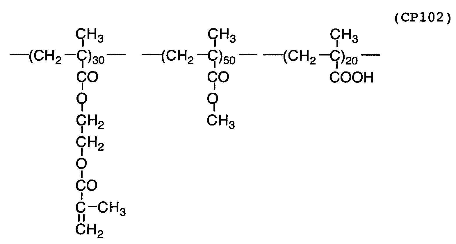


Claims (23)
- A lithographic process comprising the steps of: imagewise heating a presensitized lithographic printing plate which comprises a hydrophilic support and an image-forming layer containing a hydrophobic polymer and a compound having two or more o-quinodimethane structures or precursor structures thereof to polymerize the compound; and removing the unheated area of the image-forming layer to form a lithographic printing plate.
- The lithographic process as claimed in claim 1, wherein the image-forming layer further contains an agent capable of converting light to heat, and the presensitized lithographic printing plate is scanned with a laser beam to imagewise heat the plate.
- The lithographic process as claimed in claim 1, wherein the compound has two or more benzocyclobutene structures as the precursor structures of the o-quinodimethane structures.
- The lithographic process as claimed in claim 1, wherein the image-forming layer further contains a compound having two or more dienophile structures.
- The lithographic process as claimed in claim 1, wherein the hydrophobic polymer has dienophile structures.
- A lithographic process comprising the steps of: imagewise heating a presensitized lithographic printing plate which comprises a hydrophilic support and an image-forming layer containing a hydrophilic polymer and a compound having two or more o-quinodimethane structures or precursor structures thereof, said compound being contained in particles dispersed in the hydrophilic polymer to polymerize the compound and to fuse the particles together; and removing the unheated area of the image-forming layer to form a lithographic printing plate.
- The lithographic process as claimed in claim 6, wherein the image-forming layer further contains an agent capable of converting light to heat, and the presensitized lithographic printing plate is scanned with a laser beam to imagewise heat the plate.
- The lithographic process as claimed in claim 6, wherein the compound has two or more benzocyclobutene structures as the precursor structures of the o-quinodimethane structures.
- The lithographic process as claimed in claim 1, wherein the image-forming layer further contains a compound having two or more dienophile structures.
- The lithographic process as claimed in claim 1, wherein the particles further contain a hydrophobic polymer.
- The lithographic process as claimed in claim 10, wherein the hydrophobic polymer has dienophile structures.
- A lithographic printing process comprising the steps of: imagewise heating a presensitized lithographic printing plate which comprises a hydrophilic support and an image-forming layer containing a hydrophilic polymer and a compound having two or more o-quinodimethane structures or precursor structures thereof, said compound being contained in particles dispersed in the hydrophilic polymer to polymerize the compound and to fuse the particles together; attaching the plate to a printer; working the printer to remove the unheated area of the image-forming layer and to form a lithographic printing plate; and printing with the formed plate by supplying oily ink and dampening water to the plate.
- A presensitized lithographic printing plate which comprises a hydrophilic support and an image-forming layer containing a hydrophobic polymer and a compound having two or more o-quinodimethane structures or precursor structures thereof.
- A presensitized lithographic printing plate which comprises a hydrophilic support and an image-forming layer containing a hydrophilic polymer and a compound having two or more o-quinodimethane structures or precursor structures thereof, said compound being contained in particles dispersed in the hydrophilic polymer.
- A lithographic process comprising the steps of: imagewise heating a presensitized lithographic printing plate which comprises a hydrophilic support and an image-forming layer containing a hydrophobic polymer having o-quinodimethane structures or precursor structures thereof to cross-link the hydrophobic polymer; and removing the unheated area of the image-forming layer to form a lithographic printing plate.
- The lithographic process as claimed in claim 15, wherein the image-forming layer further contains a hydrophilic polymer, the hydrophobic polymer is contained in particles dispersed in the hydrophilic polymer, and the hydrophobic polymer is cross-linked to fuse the particles together.
- The lithographic process as claimed in claim 15, wherein the image-forming layer further contains an agent capable of converting light to heat, and the presensitized lithographic printing plate is scanned with a laser beam to imagewise heat the plate.
- The lithographic process as claimed in claim 15, wherein the hydrophobic polymer has benzocyclobutene structures as the precursor structures of the o-quinodimethane structures.
- The lithographic process as claimed in claim 15, wherein the image-forming layer further contains a compound having two or more dienophile structures.
- The lithographic process as claimed in claim 15, wherein the image-forming layer further contains a polymer having dienophile structures.
- A lithographic printing process comprising the steps of: imagewise heating a presensitized lithographic printing plate which comprises a hydrophilic support and an image-forming layer containing a hydrophilic polymer and a hydrophobic polymer having o-quinodimethane structures or precursor structures thereof, said hydrophobic polymer being contained in particles dispersed in the hydrophilic polymer to cross-link the hydrophobic polymer and to fuse the particles together; attaching the plate to a printer; working the printer to remove the unheated area of the image-forming layer and to form a lithographic printing plate; and printing with the formed plate by supplying oily ink and dampening water to the plate.
- A presensitized lithographic printing plate which comprises a hydrophilic support and an image-forming layer containing a hydrophobic polymer having o-quinodimethane structures or precursor structures thereof.
- The presensitized lithographic printing plate as claimed in claim 22, wherein the image-forming layer further contains a hydrophilic polymer, and the hydrophobic polymer is contained in particles dispersed in the hydrophilic polymer.
Applications Claiming Priority (6)
| Application Number | Priority Date | Filing Date | Title |
|---|---|---|---|
| JP2001234969 | 2001-08-02 | ||
| JP2001234969 | 2001-08-02 | ||
| JP2001384096 | 2001-12-18 | ||
| JP2001384096A JP3842639B2 (en) | 2001-12-18 | 2001-12-18 | Planographic printing plate making method, lithographic printing method, and lithographic printing original plate |
| JP2002099151A JP3847201B2 (en) | 2001-08-02 | 2002-04-01 | Image forming method, planographic printing plate making method and planographic printing method |
| JP2002099151 | 2002-04-01 |
Publications (3)
| Publication Number | Publication Date |
|---|---|
| EP1281514A2 true EP1281514A2 (en) | 2003-02-05 |
| EP1281514A3 EP1281514A3 (en) | 2003-11-26 |
| EP1281514B1 EP1281514B1 (en) | 2006-09-20 |
Family
ID=27347264
Family Applications (1)
| Application Number | Title | Priority Date | Filing Date |
|---|---|---|---|
| EP02015574A Expired - Lifetime EP1281514B1 (en) | 2001-08-02 | 2002-07-12 | Lithographic printing plate and lithographic process |
Country Status (5)
| Country | Link |
|---|---|
| US (1) | US6780567B2 (en) |
| EP (1) | EP1281514B1 (en) |
| CN (1) | CN100474107C (en) |
| AT (1) | ATE340074T1 (en) |
| DE (1) | DE60214803T2 (en) |
Cited By (4)
| Publication number | Priority date | Publication date | Assignee | Title |
|---|---|---|---|---|
| EP1614539A1 (en) * | 2004-07-08 | 2006-01-11 | Agfa-Gevaert | Method for making a lithographic printing plate |
| EP1614540A1 (en) * | 2004-07-08 | 2006-01-11 | Agfa-Gevaert | Method for making a lithographic printing plate |
| US7354696B2 (en) | 2004-07-08 | 2008-04-08 | Agfa Graphics Nv | Method for making a lithographic printing plate |
| US7425405B2 (en) | 2004-07-08 | 2008-09-16 | Agfa Graphics, N.V. | Method for making a lithographic printing plate |
Families Citing this family (8)
| Publication number | Priority date | Publication date | Assignee | Title |
|---|---|---|---|---|
| EP1560611A1 (en) * | 2002-11-05 | 2005-08-10 | Jingjiao Guan | Self-folding polymer microparticles |
| EP2278404A3 (en) | 2004-05-19 | 2011-04-27 | Agfa Graphics N.V. | Method of making a photopolymer printing plate |
| EP1817166B1 (en) * | 2004-10-01 | 2010-01-20 | Agfa Graphics Nv | Method of making lithographic printing plates |
| US20060188811A1 (en) * | 2005-02-24 | 2006-08-24 | Kunio Tani | Planographic printing plate material and printing process |
| WO2010006948A1 (en) * | 2008-07-16 | 2010-01-21 | Agfa Graphics Nv | A method and apparatus for preparing lithographic printing plate precursors |
| JP6742686B2 (en) * | 2013-11-14 | 2020-08-19 | ローム アンド ハース エレクトロニック マテリアルズ エルエルシーRohm and Haas Electronic Materials LLC | Gap filling method |
| US9490117B2 (en) | 2013-12-31 | 2016-11-08 | Dow Global Technologies Llc | Directed self-assembly pattern formation methods and compositions |
| KR102308361B1 (en) * | 2013-12-31 | 2021-10-01 | 다우 글로벌 테크놀로지스 엘엘씨 | Crosslinkable polymers and underlayer compositions |
Citations (7)
| Publication number | Priority date | Publication date | Assignee | Title |
|---|---|---|---|---|
| US2800457A (en) | 1953-06-30 | 1957-07-23 | Ncr Co | Oil-containing microscopic capsules and method of making them |
| JPS3819574B1 (en) | 1961-11-16 | 1963-09-26 | ||
| GB952807A (en) | 1961-09-05 | 1964-03-18 | Ncr Co | Process for manufacturing minute capsules having waxy material walls |
| GB990443A (en) | 1962-05-14 | 1965-04-28 | Standard Telephones Cables Ltd | Arrangement for separating two conveyer-tube sections in pneumatic tube systems |
| US4001140A (en) | 1974-07-10 | 1977-01-04 | Ncr Corporation | Capsule manufacture |
| EP0770494A2 (en) | 1995-10-24 | 1997-05-02 | Agfa-Gevaert N.V. | A method for making a lithographic printing plate involving on press development |
| US6030750A (en) | 1995-10-24 | 2000-02-29 | Agfa-Gevaert. N.V. | Method for making a lithographic printing plate involving on press development |
Family Cites Families (4)
| Publication number | Priority date | Publication date | Assignee | Title |
|---|---|---|---|---|
| JP3213001B2 (en) * | 1991-12-10 | 2001-09-25 | ザ ダウ ケミカル カンパニー | Photocurable cyclobutarene composition |
| TW437040B (en) * | 1998-08-12 | 2001-05-28 | Applied Materials Inc | Interconnect line formed by dual damascene using dielectric layers having dissimilar etching characteristics |
| US6919164B2 (en) * | 2001-06-08 | 2005-07-19 | The Penn State Research Foundation | Patterning compositions using E-beam lithography and structures and devices made thereby |
| WO2003010565A2 (en) * | 2001-07-26 | 2003-02-06 | The Penn State Research Foundation | Optical waveguides and grating structures fabricated using polymeric dielectric compositions |
-
2002
- 2002-07-08 US US10/189,551 patent/US6780567B2/en not_active Expired - Fee Related
- 2002-07-12 EP EP02015574A patent/EP1281514B1/en not_active Expired - Lifetime
- 2002-07-12 AT AT02015574T patent/ATE340074T1/en not_active IP Right Cessation
- 2002-07-12 DE DE60214803T patent/DE60214803T2/en not_active Expired - Lifetime
- 2002-08-02 CN CN02128222.6A patent/CN100474107C/en not_active Expired - Fee Related
Patent Citations (8)
| Publication number | Priority date | Publication date | Assignee | Title |
|---|---|---|---|---|
| US2800457A (en) | 1953-06-30 | 1957-07-23 | Ncr Co | Oil-containing microscopic capsules and method of making them |
| GB952807A (en) | 1961-09-05 | 1964-03-18 | Ncr Co | Process for manufacturing minute capsules having waxy material walls |
| JPS3819574B1 (en) | 1961-11-16 | 1963-09-26 | ||
| GB990443A (en) | 1962-05-14 | 1965-04-28 | Standard Telephones Cables Ltd | Arrangement for separating two conveyer-tube sections in pneumatic tube systems |
| US4001140A (en) | 1974-07-10 | 1977-01-04 | Ncr Corporation | Capsule manufacture |
| EP0770494A2 (en) | 1995-10-24 | 1997-05-02 | Agfa-Gevaert N.V. | A method for making a lithographic printing plate involving on press development |
| US6030750A (en) | 1995-10-24 | 2000-02-29 | Agfa-Gevaert. N.V. | Method for making a lithographic printing plate involving on press development |
| US6096481A (en) | 1995-10-24 | 2000-08-01 | Agfa-Gevaert, N.V. | Method for making a lithographic printing plate involving on press development |
Cited By (4)
| Publication number | Priority date | Publication date | Assignee | Title |
|---|---|---|---|---|
| EP1614539A1 (en) * | 2004-07-08 | 2006-01-11 | Agfa-Gevaert | Method for making a lithographic printing plate |
| EP1614540A1 (en) * | 2004-07-08 | 2006-01-11 | Agfa-Gevaert | Method for making a lithographic printing plate |
| US7354696B2 (en) | 2004-07-08 | 2008-04-08 | Agfa Graphics Nv | Method for making a lithographic printing plate |
| US7425405B2 (en) | 2004-07-08 | 2008-09-16 | Agfa Graphics, N.V. | Method for making a lithographic printing plate |
Also Published As
| Publication number | Publication date |
|---|---|
| US20030165778A1 (en) | 2003-09-04 |
| CN1405629A (en) | 2003-03-26 |
| EP1281514B1 (en) | 2006-09-20 |
| DE60214803T2 (en) | 2007-10-25 |
| DE60214803D1 (en) | 2006-11-02 |
| EP1281514A3 (en) | 2003-11-26 |
| ATE340074T1 (en) | 2006-10-15 |
| US6780567B2 (en) | 2004-08-24 |
| CN100474107C (en) | 2009-04-01 |
Similar Documents
| Publication | Publication Date | Title |
|---|---|---|
| EP1629977B1 (en) | Lithographic printing process | |
| US6780567B2 (en) | Lithographic process using reaction of o-quinodimethane | |
| US20090087779A1 (en) | Printing plate material | |
| JP2005047181A (en) | Plate-making method for lithographic printing plate, lithographic printing method and lithographic printing original plate | |
| US7001704B2 (en) | Presensitized lithographic plate comprising microcapsules | |
| EP1391296B1 (en) | Presensitized lithographic plate comprising microcapsules | |
| EP1287985B1 (en) | Lithographic printing plate precursor | |
| JP3842639B2 (en) | Planographic printing plate making method, lithographic printing method, and lithographic printing original plate | |
| JP3847201B2 (en) | Image forming method, planographic printing plate making method and planographic printing method | |
| JP2005262708A (en) | Original plate of lithographic printing plate and lithographic printing method | |
| JP2003326867A (en) | Lithographic printing method and lithographic printing original plate | |
| JP4054648B2 (en) | Planographic printing original plate, planographic printing plate making method and planographic printing method | |
| JP2005119129A (en) | Lithographic original plate, making method of lithographic plate and lithographic method | |
| JP2002225451A (en) | Original plate for lithographic printing plate | |
| JP2003063164A (en) | Original plate for lithographic printing | |
| JP2004358698A (en) | Lithographic printing original plate, manufacturing method for lithographic printing plate and lithographic printing method | |
| JP2002283758A (en) | Original film for planographic printing plate | |
| JP2003295420A (en) | Method for making planographic printing plate, planographic printing method and planographic printing plate precursor | |
| JP2003034087A (en) | Lithographic printing plate original plate | |
| JP2004209876A (en) | Printing method using original plate of heat-sensitive lithographic printing plate | |
| JP2003005358A (en) | Image forming material and original plate for planographic printing plate | |
| JP2004243582A (en) | Method for printing using dampening water for lithographic printing plate and original printing plate for thermal lithographic printing plate | |
| JP2004090436A (en) | Lithographic printing original plate, platemaking method for lithographic printing plate, and lithographic printing method | |
| JP2002264556A (en) | Image forming material and original plate for lithographic printing plate | |
| JP2004106226A (en) | Printing method for original plate of heat sensitive lithographic printing plate |
Legal Events
| Date | Code | Title | Description |
|---|---|---|---|
| PUAI | Public reference made under article 153(3) epc to a published international application that has entered the european phase |
Free format text: ORIGINAL CODE: 0009012 |
|
| AK | Designated contracting states |
Designated state(s): AT BE BG CH CY CZ DE DK EE ES FI FR GB GR IE IT LI LU MC NL PT SE SK TR |
|
| AX | Request for extension of the european patent |
Extension state: AL LT LV MK RO SI |
|
| PUAL | Search report despatched |
Free format text: ORIGINAL CODE: 0009013 |
|
| AK | Designated contracting states |
Kind code of ref document: A3 Designated state(s): AT BE BG CH CY CZ DE DK EE ES FI FR GB GR IE IT LI LU MC NL PT SE SK TR |
|
| AX | Request for extension of the european patent |
Extension state: AL LT LV MK RO SI |
|
| 17P | Request for examination filed |
Effective date: 20040305 |
|
| AKX | Designation fees paid |
Designated state(s): AT BE BG CH CY CZ DE DK EE ES FI FR GB GR IE IT LI LU MC NL PT SE SK TR |
|
| GRAP | Despatch of communication of intention to grant a patent |
Free format text: ORIGINAL CODE: EPIDOSNIGR1 |
|
| RTI1 | Title (correction) |
Free format text: LITHOGRAPHIC PRINTING PLATE AND LITHOGRAPHIC PROCESS |
|
| GRAS | Grant fee paid |
Free format text: ORIGINAL CODE: EPIDOSNIGR3 |
|
| GRAA | (expected) grant |
Free format text: ORIGINAL CODE: 0009210 |
|
| AK | Designated contracting states |
Kind code of ref document: B1 Designated state(s): AT BE BG CH CY CZ DE DK EE ES FI FR GB GR IE IT LI LU MC NL PT SE SK TR |
|
| PG25 | Lapsed in a contracting state [announced via postgrant information from national office to epo] |
Ref country code: BE Free format text: LAPSE BECAUSE OF FAILURE TO SUBMIT A TRANSLATION OF THE DESCRIPTION OR TO PAY THE FEE WITHIN THE PRESCRIBED TIME-LIMIT Effective date: 20060920 Ref country code: IT Free format text: LAPSE BECAUSE OF FAILURE TO SUBMIT A TRANSLATION OF THE DESCRIPTION OR TO PAY THE FEE WITHIN THE PRESCRIBED TIME-LIMIT;WARNING: LAPSES OF ITALIAN PATENTS WITH EFFECTIVE DATE BEFORE 2007 MAY HAVE OCCURRED AT ANY TIME BEFORE 2007. THE CORRECT EFFECTIVE DATE MAY BE DIFFERENT FROM THE ONE RECORDED. Effective date: 20060920 Ref country code: CH Free format text: LAPSE BECAUSE OF FAILURE TO SUBMIT A TRANSLATION OF THE DESCRIPTION OR TO PAY THE FEE WITHIN THE PRESCRIBED TIME-LIMIT Effective date: 20060920 Ref country code: AT Free format text: LAPSE BECAUSE OF FAILURE TO SUBMIT A TRANSLATION OF THE DESCRIPTION OR TO PAY THE FEE WITHIN THE PRESCRIBED TIME-LIMIT Effective date: 20060920 Ref country code: CZ Free format text: LAPSE BECAUSE OF FAILURE TO SUBMIT A TRANSLATION OF THE DESCRIPTION OR TO PAY THE FEE WITHIN THE PRESCRIBED TIME-LIMIT Effective date: 20060920 Ref country code: SK Free format text: LAPSE BECAUSE OF FAILURE TO SUBMIT A TRANSLATION OF THE DESCRIPTION OR TO PAY THE FEE WITHIN THE PRESCRIBED TIME-LIMIT Effective date: 20060920 Ref country code: NL Free format text: LAPSE BECAUSE OF FAILURE TO SUBMIT A TRANSLATION OF THE DESCRIPTION OR TO PAY THE FEE WITHIN THE PRESCRIBED TIME-LIMIT Effective date: 20060920 Ref country code: FI Free format text: LAPSE BECAUSE OF FAILURE TO SUBMIT A TRANSLATION OF THE DESCRIPTION OR TO PAY THE FEE WITHIN THE PRESCRIBED TIME-LIMIT Effective date: 20060920 Ref country code: LI Free format text: LAPSE BECAUSE OF FAILURE TO SUBMIT A TRANSLATION OF THE DESCRIPTION OR TO PAY THE FEE WITHIN THE PRESCRIBED TIME-LIMIT Effective date: 20060920 |
|
| REG | Reference to a national code |
Ref country code: GB Ref legal event code: FG4D |
|
| REG | Reference to a national code |
Ref country code: CH Ref legal event code: EP |
|
| REG | Reference to a national code |
Ref country code: IE Ref legal event code: FG4D |
|
| REF | Corresponds to: |
Ref document number: 60214803 Country of ref document: DE Date of ref document: 20061102 Kind code of ref document: P |
|
| PG25 | Lapsed in a contracting state [announced via postgrant information from national office to epo] |
Ref country code: BG Free format text: LAPSE BECAUSE OF FAILURE TO SUBMIT A TRANSLATION OF THE DESCRIPTION OR TO PAY THE FEE WITHIN THE PRESCRIBED TIME-LIMIT Effective date: 20061220 Ref country code: SE Free format text: LAPSE BECAUSE OF FAILURE TO SUBMIT A TRANSLATION OF THE DESCRIPTION OR TO PAY THE FEE WITHIN THE PRESCRIBED TIME-LIMIT Effective date: 20061220 Ref country code: DK Free format text: LAPSE BECAUSE OF FAILURE TO SUBMIT A TRANSLATION OF THE DESCRIPTION OR TO PAY THE FEE WITHIN THE PRESCRIBED TIME-LIMIT Effective date: 20061220 |
|
| PG25 | Lapsed in a contracting state [announced via postgrant information from national office to epo] |
Ref country code: ES Free format text: LAPSE BECAUSE OF FAILURE TO SUBMIT A TRANSLATION OF THE DESCRIPTION OR TO PAY THE FEE WITHIN THE PRESCRIBED TIME-LIMIT Effective date: 20061231 |
|
| NLV1 | Nl: lapsed or annulled due to failure to fulfill the requirements of art. 29p and 29m of the patents act | ||
| PG25 | Lapsed in a contracting state [announced via postgrant information from national office to epo] |
Ref country code: PT Free format text: LAPSE BECAUSE OF FAILURE TO SUBMIT A TRANSLATION OF THE DESCRIPTION OR TO PAY THE FEE WITHIN THE PRESCRIBED TIME-LIMIT Effective date: 20070312 |
|
| RAP2 | Party data changed (patent owner data changed or rights of a patent transferred) |
Owner name: FUJIFILM CORPORATION |
|
| REG | Reference to a national code |
Ref country code: CH Ref legal event code: PL |
|
| EN | Fr: translation not filed | ||
| REG | Reference to a national code |
Ref country code: GB Ref legal event code: 732E |
|
| PLBE | No opposition filed within time limit |
Free format text: ORIGINAL CODE: 0009261 |
|
| STAA | Information on the status of an ep patent application or granted ep patent |
Free format text: STATUS: NO OPPOSITION FILED WITHIN TIME LIMIT |
|
| 26N | No opposition filed |
Effective date: 20070621 |
|
| PG25 | Lapsed in a contracting state [announced via postgrant information from national office to epo] |
Ref country code: FR Free format text: LAPSE BECAUSE OF FAILURE TO SUBMIT A TRANSLATION OF THE DESCRIPTION OR TO PAY THE FEE WITHIN THE PRESCRIBED TIME-LIMIT Effective date: 20070518 Ref country code: GR Free format text: LAPSE BECAUSE OF FAILURE TO SUBMIT A TRANSLATION OF THE DESCRIPTION OR TO PAY THE FEE WITHIN THE PRESCRIBED TIME-LIMIT Effective date: 20061221 Ref country code: MC Free format text: LAPSE BECAUSE OF NON-PAYMENT OF DUE FEES Effective date: 20070731 |
|
| PG25 | Lapsed in a contracting state [announced via postgrant information from national office to epo] |
Ref country code: EE Free format text: LAPSE BECAUSE OF FAILURE TO SUBMIT A TRANSLATION OF THE DESCRIPTION OR TO PAY THE FEE WITHIN THE PRESCRIBED TIME-LIMIT Effective date: 20060920 |
|
| PG25 | Lapsed in a contracting state [announced via postgrant information from national office to epo] |
Ref country code: IE Free format text: LAPSE BECAUSE OF NON-PAYMENT OF DUE FEES Effective date: 20070712 |
|
| PG25 | Lapsed in a contracting state [announced via postgrant information from national office to epo] |
Ref country code: FR Free format text: LAPSE BECAUSE OF FAILURE TO SUBMIT A TRANSLATION OF THE DESCRIPTION OR TO PAY THE FEE WITHIN THE PRESCRIBED TIME-LIMIT Effective date: 20060920 |
|
| PG25 | Lapsed in a contracting state [announced via postgrant information from national office to epo] |
Ref country code: CY Free format text: LAPSE BECAUSE OF FAILURE TO SUBMIT A TRANSLATION OF THE DESCRIPTION OR TO PAY THE FEE WITHIN THE PRESCRIBED TIME-LIMIT Effective date: 20060920 Ref country code: LU Free format text: LAPSE BECAUSE OF NON-PAYMENT OF DUE FEES Effective date: 20070712 |
|
| PG25 | Lapsed in a contracting state [announced via postgrant information from national office to epo] |
Ref country code: TR Free format text: LAPSE BECAUSE OF FAILURE TO SUBMIT A TRANSLATION OF THE DESCRIPTION OR TO PAY THE FEE WITHIN THE PRESCRIBED TIME-LIMIT Effective date: 20060920 |
|
| PGFP | Annual fee paid to national office [announced via postgrant information from national office to epo] |
Ref country code: GB Payment date: 20120711 Year of fee payment: 11 |
|
| PGFP | Annual fee paid to national office [announced via postgrant information from national office to epo] |
Ref country code: DE Payment date: 20120704 Year of fee payment: 11 |
|
| GBPC | Gb: european patent ceased through non-payment of renewal fee |
Effective date: 20130712 |
|
| REG | Reference to a national code |
Ref country code: DE Ref legal event code: R119 Ref document number: 60214803 Country of ref document: DE Effective date: 20140201 |
|
| PG25 | Lapsed in a contracting state [announced via postgrant information from national office to epo] |
Ref country code: GB Free format text: LAPSE BECAUSE OF NON-PAYMENT OF DUE FEES Effective date: 20130712 Ref country code: DE Free format text: LAPSE BECAUSE OF NON-PAYMENT OF DUE FEES Effective date: 20140201 |