EP1280355A2 - Method and apparatus for connecting a television interphone monitor system to a concierge station over internet - Google Patents
Method and apparatus for connecting a television interphone monitor system to a concierge station over internet Download PDFInfo
- Publication number
- EP1280355A2 EP1280355A2 EP02251796A EP02251796A EP1280355A2 EP 1280355 A2 EP1280355 A2 EP 1280355A2 EP 02251796 A EP02251796 A EP 02251796A EP 02251796 A EP02251796 A EP 02251796A EP 1280355 A2 EP1280355 A2 EP 1280355A2
- Authority
- EP
- European Patent Office
- Prior art keywords
- television interphone
- interphone monitor
- concierge
- communication network
- interface unit
- Prior art date
- Legal status (The legal status is an assumption and is not a legal conclusion. Google has not performed a legal analysis and makes no representation as to the accuracy of the status listed.)
- Granted
Links
Images


Classifications
-
- H—ELECTRICITY
- H04—ELECTRIC COMMUNICATION TECHNIQUE
- H04M—TELEPHONIC COMMUNICATION
- H04M11/00—Telephonic communication systems specially adapted for combination with other electrical systems
- H04M11/04—Telephonic communication systems specially adapted for combination with other electrical systems with alarm systems, e.g. fire, police or burglar alarm systems
-
- H—ELECTRICITY
- H04—ELECTRIC COMMUNICATION TECHNIQUE
- H04N—PICTORIAL COMMUNICATION, e.g. TELEVISION
- H04N7/00—Television systems
- H04N7/14—Systems for two-way working
- H04N7/141—Systems for two-way working between two video terminals, e.g. videophone
- H04N7/148—Interfacing a video terminal to a particular transmission medium, e.g. ISDN
-
- H—ELECTRICITY
- H04—ELECTRIC COMMUNICATION TECHNIQUE
- H04N—PICTORIAL COMMUNICATION, e.g. TELEVISION
- H04N7/00—Television systems
- H04N7/18—Closed-circuit television [CCTV] systems, i.e. systems in which the video signal is not broadcast
- H04N7/183—Closed-circuit television [CCTV] systems, i.e. systems in which the video signal is not broadcast for receiving images from a single remote source
- H04N7/186—Video door telephones
Definitions
- This invention relates to a television interphone apparatus provided for communication between building entrances and individual apartments of the building, along with transmission of visitor's pictures to a monitor mounted on the wall of the apartment, or to a concierge counter and/or to a concierge/service center over the internet.
- a television interphone monitor used for entrance monitoring and communications is mounted on a wall inside the apartment and is wired via multi-core cables for connecting to each other different elements of the system, such as a microphone and speaker wires, a coax cable for video signals, a door release wire, a calling wire and an alarm wire.
- a microphone and speaker wires such as a microphone and speaker wires, a coax cable for video signals, a door release wire, a calling wire and an alarm wire.
- U.S patent number 5.923.363 Another type of television interphone monitoring system is disclosed in U.S patent number 5.923.363, wherein the entrance unit comprises a matrix switching apparatus for connecting a plurality of entrance units and concierge units to multiple apartments simultaneously.
- An object of the present invention is provide a method and apparatus for connecting a television interphone monitoring system via wired or wireless, dedicated or public telephone or other networks and/or via the internet to an E concierge station, providing the tenants and visitors alike with non limited concierge services around the clock.
- Another object of the present invention is to provide for a simple recall of the E concierge station via a simple key touch, and to further simplify the communication with the operators of the E concierge station by providing two way voice and picture or data communications, thereby allowing small children and the elderly that are unable to operate a PC or other internet interfacing device, a simple, fast and efficient recall of the E concierge station and request a variety of services by communicating through the handset and the monitor of the television interphone monitor and/or through the entrance panel, using the voice, picture and data communicating facilities of the television interphone monitoring system.
- An apparatus for connecting a television interphone monitoring system via a public telephone line to an E concierge station comprises a single entrance panel or a plurality of entrance panels each comprising a microphone and a speaker, and each of which may comprise a television camera and a display monitor and each of the entrance panel processing an electrical information signal including two-way audio signals and/or one or two-way video signals and/or data signal, a single television interphone monitor or a plurality of television interphone monitors for communication with and observing the visitors, a single transmission line or a plurality of transmission lines for connecting each television interphone monitor with a central unit or directly with the single entrance panel or the plurality of entrance panels.
- the central unit may include a circuit for feeding an information signal to a television interphone monitor and a circuit for receiving the information signal from the television interphone monitors through corresponding transmission lines.
- the central unit and the television interphone monitors may be connected through matrix switching circuits for connecting any one of the entrance panels to any one of the television interphone monitors or switching over from one entrance panel to another or from one television interphone monitor to another.
- the central unit may incorporate a signal separation/injection circuit to inject video signals generated by the television camera along with audio, data, control and alarm signals for propagating combined information signals through the transmission lines to the television interphone monitor or to a concierge station or to the E concierge station via dedicated or public telephone lines or via wireless telephone or other communication network or via the internet.
- a signal separation/injection circuit can be installed in the switching circuits of the central unit to inject or separate from the transmission line the information signals processed by the switching circuit, or multiple separation/injection circuits can be incorporated one per each transmission line.
- the separation/injection circuit also separates the information signal propagated through the transmission line from any DC components present on the transmission line whenever the television monitor interphone is powered via the transmission line, and feeds the separated information signal to the receiving circuit of the entrance unit.
- the receiving circuit may comprise decoding/demodulating circuits for feeding the video, audio, data, control and alarm signals to the respective circuits.
- Each television interphone monitor may further incorporate a signal combining circuit to process and combine video, audio, data, control and alarm signals generated by the television interphone monitor, and an injection circuit to inject the combined signals that form an information signal into the transmission line connecting the television interphone monitor with the central unit or the entrance unit or the concierge station or the E concierge station.
- a signal combining circuit to process and combine video, audio, data, control and alarm signals generated by the television interphone monitor
- an injection circuit to inject the combined signals that form an information signal into the transmission line connecting the television interphone monitor with the central unit or the entrance unit or the concierge station or the E concierge station.
- the interphone television monitor of the present invention may further comprise a television camera for generating video signals, a control circuit for generating and feeding a control signal consisting of a coded control command such as a code for controlling the entrance door lock and/or a code for controlling the elevators, or a code for controlling the lighting of corridors and the entrance.
- the coded control command may include alarm signals for alerting a concierge or a security attendant.
- the coded control command may also include a switch-on control command for connecting the television interphone monitor with any of the entrance panels or switching over from one entrance panel to another or for connecting the television interphone monitor with a concierge station or with a security room or with the E concierge station.
- the coded control signals may use a binary code or digital codes consisting of high-low or narrow-wide pulses or use dual tone signals used for a digital telephone, or use a specific frequency or a pulse count, or a mixture of different pulses and frequencies for a given control command.
- the coded control can be AM or FM and combined into the audio frequency range and mixed with the audio and/or video signals propagated between the television interphone monitor and the entrance unit.
- Similar or identical coded control signals are also generated by the central unit or the entrance panel for controlling individual functions related to each television interphone monitor, such as ringing, switching the monitor on, a fire alarm annunciation, a general alarm annunciation, switching the lighting of corridors on-off, or blocking the elevators and/or many other coded controls for operating functions of a concierge and/or alarm attendant for an apartments' building or a block.
- the video signals generated by the television camera may be converted into differential signals for propagation via low cost transmission lines such as a twisted pair and may be processed into digital video signals, or modulated onto a carrier frequency.
- the video and audio signals along with the control and alarm signals generated by the entrance panel or the central unit and the television interphone monitor may also be converted into differential signals or digital signals and may be AM or FM modulated onto a carrier frequency having a frequency higher or lower than the video frequency and propagated through the transmission line connecting the television interphone monitor with the central unit and/or with the entrance unit.
- the video signals may be compressed signals and the audio signals along with the control and alarm signals may also be compressed and mixed into the video signals preferably during the vertical blanking period.
- the entrance unit, or the central unit or the television interphone monitor unit may further comprise or be connected to an internet interface unit which converts the video, audio, data, control and alarm signals to digital signals for propagating the digital signals through wired or wireless, dedicated or public, digital or analog telephone or other communication network for connecting the video interphone system to the E concierge station.
- the internet interface unit may be a well known PC with modem and provided with software for video, audio and data communication via the internet or it can be a well known micro processor based interface with limited applications, specifically designed for communication with a given internet station.
- the well known PC or the micro processor based interface may also be provided with video, audio and data recording facilities, for recording all visitors along with the time and date of their visit as well as recording all events and for storing and safe keeping the recorded data for long periods.
- the video recorder, digital or analog and/or audio recorder can be separately connected to an entrance unit or to the central unit for recording all visitors and events, while a recorded data can be replayed onto a television interphone monitor, or onto a concierge station or onto a guard station via playback command by a tenant, a security guard, a concierge or the E concierge station.
- the video signals and the audio signals along with data, alarm and control signals can be bi-directionally propagated through a low cost transmission line extending between the central unit and the television interphone monitor, and via telephone lines or other public or dedicated communications networks between the central unit and E concierge station, while a regulated current as disclosed in U.S. patent 5,923,363, may be fed to the television interphone monitors through same low cost transmission line connecting the central unit and the television interphone monitors.
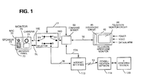
- FIG.1 shows an apparatus for connecting a single television interphone monitor system to an E concierge station over the Internet as a preferred embodiment when applying the present invention to a television interphone monitoring system.
- An information signal in the following description may consist of audio or video signals only, or a combination of video, audio, alarm, data and code signals propagated between an entrance panel, concierge or guard station and a television interphone monitor, and/or between an E concierge station and a television interphone monitor, and/or between and E concierge station and an entrance panel, concierge or guard station, and/or between E concierge station and a television interphone monitor, simultaneously with an entrance panel, concierge or guard station.
- a video signal in the following description may be a video portion of a composite video signal or a composite video signal or a digital video signal. Audio signals in the following description may be an analog or digital signals, while the video signal and/or the audio signal and/or the data signal may be compressed signals.
- the apparatus for connecting a television interphone monitor system to a concierge station over the internet comprises an entrance panel 70 incorporating a television camera 71, a microphone 73, a speaker 74, a display monitor 75 and selector keys (not shown) for transmitting and receiving an information signal, a command sensor 50 and a selector S1/S2 for receiving and transferring the information signals to and from the entrance panel 70, a transmission line 16 for propagating information signals between the television interphone monitor 40 and the command sensor 50 and for propagating information signals between the command sensor 50 via the selector S1/S2 and the entrance panel 70.
- the television interphone monitor 40 has a display monitor circuit 44 for displaying images and an interphone circuit 45 for receiving and generating information signals.
- the television interphone monitor 40 further incorporates a data/alarm input for processing data and alarm signals and a video input for receiving video signals and for propagating the received data, alarm and video signals through the transmission line 16.
- the command sensor 50 extracts and decodes a command and control signals propagated via the transmission line 16 and feed a select command signal to selector S1/S2 through a command line 17 and to the internet interface 110 via a command line 17A.
- the selector S1/S2 can be operated via a command signal generated from the television interphone monitor 40, through the command sensor 50 and the command line 17, or via a command generated from the E concierge station via the internet interface 110 and the connect line 18, or via a command generated from the entrance panel and fed to the selector S1/S2 via the select line SL.
- the selector S1/S2 can be commanded to connect the entrance panel 70 to the television interphone monitor 40 as shown in FIG.1, or to the internet interface 110 by switching over S1 to B position or to both, the television interphone monitor 40 and the internet interface 110, by switching over both S1 and S2 to B position.
- the selector S1/S2 can be further commanded to connect the television interphone monitor 40 to the internet interface 110 by switching over S2 only to B position.
- an E concierge station By such arrangement an E concierge station, the television interphone monitor 40 and/or the entrance panel 70 can be interconnected in any configuration.
- the selectors S1 and S2 are shown as a pair of mechanical switch-over switches, but the S1 and S2 can be any well known electronic analog or digital switches or matrix switches, which are widely available in different IC packages.
- the internet interface 110 is fed with information signals via the connect line 18 and is activated to engage the E concierge station through the command line 17A and communicate with the E concierge station via the network line 19.
- the network line 19 can be any public or dedicated telephone line, hard wired, fiber optic or wireless. It can be a well-known networking line such as TCP/IP or ATM or Ethernet or it can be a communication line, directly connected to an Internet network provider or to the E concierge station.
- the E concierge station 129 which will be described, is provided with human or electronic operators, having voice, video, control, alarm and data communication facilities including common codes, data, and information signals commensurating with the codes, data and information signals used for the television interphone monitor system.
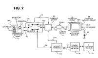
- FIG.2 shows a television interphone monitor system with a single television interphone monitor unit, identical to the system shown in FIG.1 with the exception of a current supply 14 that is added between the transmission line 16 and the transmission line 16A connecting the television interphone monitor 40A to the current supply 14.
- the transmission line 16A carries a regulated current to operate the television interphone plus charge current to charge the rechargeable battery 49 that powers the television monitor circuit 44 of the television interphone monitor 40A, which unlike the television interphone monitor 40, is not connected to a power line.
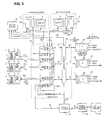
- FIG.3 shows an apparatus for connecting multiple television interphone monitors system to an E concierge station over the internet as a preferred embodiment, comprising the entrance panel 70 incorporating the television camera 71, microphone 73, speaker 74, display monitor 75 and selector keys (not shown) for transmitting and receiving an information signal, a command sensor 60 and two selectors S1 and S2 for receiving and transferring the information signals to and from the entrance panel 70, with the selectors S1 and S2 and the entrance panel 70 shown as part of an entrance unit 120, a plurality of transmission lines 16 for propagating information signals between two or more television interphone monitors 40, shown as 1, 2 and n, and multiple inputs command sensor 60 and for propagating information signals between the command sensor 60 via the selectors S1 and S2 and the entrance panel 70.
- Each of the television interphone monitors 40 comprises the display monitor circuit 44 for displaying images, and the interphone circuit 45 for receiving and generating information signals.
- each video interphone monitor further incorporates a data/alarm input for processing data and alarm signals and a video input for receiving video signals and for propagating the received data, alarm and video signals through a transmission line 16.
- the command sensor 60 extracts and decodes alarm, command and control signals propagated via the transmission lines 16 and feed select command signal to selector S1 and S2 through a command line 17 and to the internet interface 110 via a command line 17A.
- commands and controls the control circuit 130 may comprise a microprocessor for controlling multi tasks simultaneously, in accordance with the data fed to from the command sensor 60 through control/command line 17B.
- the selectors S1 and S2 can be operated via a command signal generated from any of the television interphone monitors 40, through the command sensor 60 and the command lines 17, 17B and 17C or via a command generated from the E concierge station via the internet interface 110 and the connect line 18, or via a command generated from the entrance panel and fed to the selectors S1 and S2 via the select line SL.
- the selector S1 can be commanded to connect the entrance panel 70 to one of the television interphone monitors 40 while another television interphone monitor 40 may be connected via selector S2 to an E concierge station via the internet interface 110.
- Such arrangement provides full flexibility in engaging the E concierge station from the entrance panel 70, any of the television interphone monitors 40 or both, or providing for separate communication lines, one between the entrance panel 70 and a television interphone monitor 40 and another between a television interphone monitor 40 and the E concierge station via the internet interface 110.
- the selectors S1 and S2 are shown in FIG.3 as a pair of manual selector switches, but similar to S1 and S2 of FIGS.1 and 2 the selector S1 and S2 of FIG.3 can be any well known electronic analog and digital switches or matrix switches, which are widely available in different IC packages.
- the internet interface 110 of FIG.3 is fed with information signals via the connect line 18 and is activated to engage the E concierge station through the command line 17A and communicate with the E concierge station via the network line 19.
- the network line 19 can be any public or dedicated telephone line, hard wired, fiber optic or wireless. It can be a well-known networking line such as TCP/IP or ATM or Ethernet or it can be a communication line, directly connected to an Internet network provider or to an E concierge station.
- the E concierge station is provided with human or electronic operators, having voice, video, controls, alarm and data communication facilities including common codes, data, and information signals commensurating with the codes, data and information signals used by the television interphone monitor system.
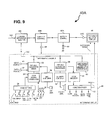
- FIG.4 shows a television interphone monitor system with multiple television interphone monitors 40A, identical to the system shown in FIG.3 with exception of the multiple current supply units 14 which are added between the transmission lines 16 and 16A connecting the video interphone monitors 40a with the current supply units 14.
- the transmission line 16A carries a regulated current to operate the television interphone plus charge current to charge the rechargeable batteries 49 that power the television monitor circuits 44 of the television interphone monitors 40A, which unlike the television interphone monitors 40, are not connected to a power line.
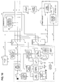
- FIG.5 shows an apparatus for connecting multiple television interphone monitors system to an E concierge station over the internet as a preferred embodiment, including multiple 1-n entrance panels 70, each incorporating television camera 71, microphone 73, speaker 74, display monitor 75 and selector keys (not shown) for transmitting and receiving an information signal.
- the apparatus further has a concierge counter 8 and a security counter 9 each having a monitor 5 and an interphone unit 6 for generating and receiving information signals and a control unit 102 for generating and receiving select and control commands, the command sensor 60 and multiple selectors SG, SC, S1-1 ⁇ S1-2, S1-n and S2, which are combined into a matrix selector assembly SM for receiving and transferring the information signals to and from the entrance panels 70, the concierge counter 8, the security counter 9 and the television interphone monitors 40 through a plurality of transmission line 16, 16-1, 16-2, 16-n, 16C, 16G and 18 and the multiple inputs command sensor 60 for retrieving command signals from the information signals propagated through the command sensor 60.
- a concierge counter 8 and a security counter 9 each having a monitor 5 and an interphone unit 6 for generating and receiving information signals and a control unit 102 for generating and receiving select and control commands, the command sensor 60 and multiple selectors SG, SC, S1-1 ⁇ S1-2, S1-n and S2, which
- Each of the television interphone monitors 40 includes display monitor circuit 44 for displaying images, and an interphone circuit 45 for receiving and generating information signals and similar to the television interphone monitor 40 of FIG.1 or FIG.3, each video interphone monitor further incorporates a data/alarm input for processing data and alarm signals and a video input for receiving video signals and for propagating the received data, alarm and video signals through a respective transmission line 16.
- the command sensor 60 extracts and decodes alarm, command and control signals propagated via the transmission lines 16 and feed select command signal to a master control unit 101 and to the internet interface 110 via command lines 17A.
- the master control 101 commands and controls the control circuits 102 of the concierge counter 8, the security counter and the matrix selector assembly SM via select line 101A simultaneously, in accordance to the data fed to it from the command sensor 60 through control/command line 17B.
- Each of the selectors S1-1 to S1-n can be operated via a command signal generated from any of the television interphone monitors 40, through the command sensor 60 and the command lines 17B or via a command generated from the E concierge station via the internet interface 110 and the connect line 18, or via a command generated from an entrance panel and fed to the selectors S1-1 and S1-n via the select lines SL.
- the selectors S1-1 to S1-n can be commanded to connect each respective entrance panel 70 to one television interphone monitors 40, while other television interphone monitors 40 may be connected via selectors SG, SC and S2 to the concierge counter 8, the security counter 9 and to an E concierge station via the internet interface 110.
- an entrance panel 70 or the concierge counter 8 or the security counter 9 to the internet interface 110 via selectors SC or SG or S1-1 to S1-n and S2, or to connect an entrance panel 70 or the concierge counter 8 or the security counter 9 along with one of the television interphone monitors 40 to the internet interface 110.
- Such arrangement provides full flexibility in engaging the E concierge station from any entrance panel 70, the concierge and/or the security counters and any of the television interphone monitors 40 individually or compoundly, or providing for separate communication lines, one between each entrance panel 70 and a television interphone monitor 40 and others between a television interphone monitor 40 and the concierge counter 8, the security counter 9 and E concierge station via the internet interface 110.
- the selectors SG, SC, S1-1 ⁇ S1-n and S2 are shown in FIG.5 as manual selector switches, but similar to S1 and S2 of FIG.3 the selectors of FIG.5 can be any well known array of relays or electronic analog or digital switches or matrix switches, which are widely available in different IC packages.
- the internet interface 110 of FIG.5 is fed with information signals via the connect line 18 and is activated to engage the E concierge station through the command line 17A and communicate with the E concierge station via the network line 19.
- the network line 19 can be any public or dedicated telephone line, hard wired, fiber optic or wireless. It can be a well-known networking line such as TCP/IP or ATM or Ethernet or it can be a communication line, directly connected to an Internet network provider or to an E concierge station.
- the E concierge station as explained above, is provided with human or electronic operators, having voice, video, controls, alarm and data communication facilities including common codes, data, and information signals commensurating with the codes, data and information signals used by the television interphone monitor system.
- FIG.6 shows a television interphone monitor system with multiple television interphone monitors 40A, identical to the system shown in FIG.5 with exception of the multiple current supply units 14 which are added between the transmission lines 16 and 16A connecting the video interphone monitors 40a with the current supply units 14.
- the transmission line 16A carries a regulated current to operate the television interphone plus charge current to charge the rechargeable batteries 49 that power the television monitor circuits 44 of the television interphone monitors 40A, which unlike the television interphone monitors 40, are not connected to a power line.
- the multiple current supply units 14 which are identical with the current supply units of FIG.2 and FIG.4 are fed with power supplied by a main power supply unit 7.
- FIG.7 shows a television interphone monitor system with multiple television interphone monitors 40A and multiple entrance panels 70, identical to the system shown in FIG.5 with exception of the n selectors S2-1 to S2-n which are added to an expanded matrix selector SM-X and the addition of n transmission lines 18-1 to 18-n for connecting the selectors S2-1 to S2-n with the internet interface unit 110.
- the internet interface can handle up to n simultaneous connections with the E concierge station via wide bandwidth network line 19W which provides for two-way multiplexed transmission of plurality of information signals.
- FIG.8 shows a television interphone monitor system similar to the system shown in FIG.7 with the exception of the n number of internet interface units 110, each fed with individual information signal through connect line 18-1 and up to 18-n and each internet interface individually engage the E concierge station via a network line 19.
- the multiple E concierge stations are identical with the E concierge station described in FIG.3 and FIG.5.
- the television interphone monitors 40A of FIG.8 are powered via a transmission lines 16A by current supply unit 14, which is identical with the current supply unit 14 of FIG.4 and FIG.6.
- n number of internet interfaces 110 each for connecting a single television interphone monitor 40 or 40A to an E concierge station via network line 19 can be mixed with n number of internet interfaces 110 each for connecting plurality of television interphone monitors 40 and/or 40A and/or entrance panels and/or concierge and/or security counter to the E concierge station via a wide band network line 19W.
- the video interphone monitor 40A is connected to a transmission line 16A through a DC-signal injector/separator circuit 49C for separating the DC from the received signals.
- the separator circuit 49C consists of a well-known coupling capacitor for coupling the signals and blocking the DC from the signal processing circuits and well known RF filters for removing the signals from the DC.
- the injector/separator circuit may consist of signal transformers for retrieving information signals from the DC and RF traps for the removal of the information signals from the DC line.
- the filtered DC line is fed from the injector/separator circuit 49C to a current control circuit 49B.
- the current control circuit 49B ensures that the interphone circuits 45 are fed with a controlled current through the terminal 48, and a trickle current for charging a Ni-Cd or other rechargeable battery 49 through the battery control circuit 49A.
- the battery control circuit further employs a switch for connecting the battery to the television monitor circuit through the terminal 48A for operating the monitor. The details of the regulated current supply and the use of the rechargeable battery are fully described in the U.S. patent 5,923,363.
- the television interphone monitor 40 is operated from a power source directly fed to the terminals 48 and 48A and not by a regulated current through its transmission line 16; therefore the current control circuit 49B, the battery control circuit 49A, and the DC/signal separator portion of the DC/signal separator/injector 49C, the battery 49 are not used for the television interphone monitor 40.
- the interphone circuit 45 of the television interphone monitors 40 or 40A includes a code setting circuit 34 for setting control and command codes such as opening the door lock or calling the elevator into a given floor or switching the lights on-off and/or code for operating the selector S1, S2, S1-1 to S2-n, respectively of FIG.1 to FIG.8 or for recalling the E concierge station.
- the alarm contacts 35 of the interphone circuit 45 shown in FIG.9 will set an alarm command code when activated manually or automatically through peripheral alarm equipment such as a burglar alarm.
- the interphone circuit 45 also has a code signal generator 33 which generates control and code signals, such a generating well known dial-tone frequencies used for telephone networks or such well known RS422 or RS232 serial signals and feed the coded control signals consisting of dual tone frequencies or serial signals to signal processor/mixer 32 for mixing the coded control signals with the audio signal and/or with video signals fed through terminal 46 and/or with data signal fed through terminal 47 and injects the mixed signals into the transmission line 16 via the DC-signal injector/separator circuit 49C.
- the DC-signal injector/separator circuit 49C injects the mixed audio signals via the well known coupling capacitor or signal transformer. It may also use well-known transistor/buffer amplifier circuits for feeding the mixed signal into the transmission line 16A, or to the transmission line 16.
- the code signal generator 33 of the interphone circuit 45 may consist of a digital pulse generator for transmitting digital pulse signals commensurate with the selected code, in which case the signal processor mixer 32 may generate pulse signals for mixing the digital pulses with the audio signals and for injecting the mixed audio signal into the transmission line 16 or 16A via the DC-signal injector/separator 49C.
- the interphone 45 also includes a microphone amplifier 36 coupled between the microphone 36A and the mixer 32, a signal extractor processor 38, a speaker amplifier 39 coupled to a speaker 39A, a code decoder 41 coupled to a function driver 42 and a video signal extractor demodulator 43, the functions of which will be explained below.
- the entrance panel 70 includes a code setting and generating circuit 72A for setting control codes and generating control signals similar to the codes generated by the code setting circuit 34 and code signal generating circuit 33 of FIG.9 such as activating a ringer, or opening the door lock or calling the elevator into a given floor or switching the lights on-off, call keys 72 for addressing a video interphone monitor of a given apartment, alarm and program command circuit 72B and command memory for setting alarm and other command codes which can be activated manually or automatically through peripheral alarm equipment such as burglar alarm and an E concierge call key for engaging the E concierge station.
- a code setting and generating circuit 72A for setting control codes and generating control signals similar to the codes generated by the code setting circuit 34 and code signal generating circuit 33 of FIG.9 such as activating a ringer, or opening the door lock or calling the elevator into a given floor or switching the lights on-off
- call keys 72 for addressing a video interphone monitor of a given apartment
- alarm and program command circuit 72B and command memory for setting alarm and other command codes
- the code signal setting and generating circuit 72A may consist of a dual-tone dialer IC for generating well known dial-tone frequencies used for telephone networks, or an IC for generating serial signals such as RS422 or RS232 or an IP network signals such as used for TCP/IP, Ethernet or ATM network.
- the coded control signals consisting of a single or a group of dual tone frequencies or serial signals are fed from the code signal setting and generator circuit 72A to an audio signal processor/mixer circuit 73B for mixing the coded control signals with the audio signals and for injecting the signals into transmission line 16E and to the selector S1.
- the code for calling and engaging the E concierge station can consist of well known telephone numbers for calling and engaging the E concierge station through public telephone lines or public ISDN lines, or it can be an IP code for addressing the E concierge station through a network provider, such as the Internet.
- the code for calling and engaging the E concierge station may be a combination of telephone number and an IP code, and may include password, such as used with PCs and within the Internet communications.
- the code setting circuit 34 of FIG.9 and the code setting circuit 72A of FIG.10 need not communicate the final engage call for engaging the E concierge station, as such engage call is generated by the Internet interface unit 110 on the basis of an E concierge call code set by the code setting circuits 34 or 72A.
- the code signal generator 72A shown in FIG.10 may consist of a digital pulse generator for transmitting digital pulse signals commensurate with the selected code, in which case the audio signal processor mixer 73B may generate pulse signals for mixing the pulse signals with the audio signals and for injecting the mixed audio signal into the transmission line 16E.
- the signal extractor processor 38 of the circuit 45 shown in FIG.9 extracts the audio signal from the information signals and the code decoding circuit 41 decodes the control codes fed from the signal extractor/processor 38 and feed the decoded code signal to the function driver 42 which drives the call ringer and switches the monitor circuit 44 on, or switches the lights on-off or activates an alarm.
- the code decoder 41 consist of a dual-tone or serial signal decoder IC for decoding the well known dial-tone frequencies used for telephone networks or the serial signals content and feeds the decoded control signals to the function driver 42.
- the function driver 42 consists of electronic switching/driving devices such as transistors or multiplexers ICs, or relays, or photo couplers or other well-known switching/driving devices.
- the signal extractor/processor 38 extracts the audio signal from the information signals by using well known low pass filters for extracting the lower frequency audio signals from the information signals fed from the information signal line 16D.
- the extracted audio signals are also fed to the speaker amplifier 39 and to the speaker 39A.
- the microphone 36A, microphone amplifier 36, speaker 39A and speaker amplifier 39 use well known audio components for amplifying the received audio signals and the microphone audio signals.
- the microphone amplifier 36 feeds the microphone signals to the signal processor/mixer 32 for feeding the mixed audio and microphone signals through the information signal line 16D to the DC-signal separator/injector 49C for injecting the mixed audio and microphone signals to the transmission line 16, or to the transmission line 16A.
- the coded control signals generated by the code signal generator 33 of circuit 45 shown in FIG.9 or the code signal setting and generating circuit 72A shown in FIG.10 are serial signals or digital signals or pulse signals
- the code decoder 41 shown in FIG.9 and the code decoder 76 shown in FIG.10 will employ a well known band pass filter for extracting the digital signal or pulse signals and a digital decoder for decoding the coded signals.
- the two-way audio signals generated by the entrance panels 70 shown in FIG.10 and the audio signals generated by the television interphone monitor 40 or 40A can be propagated along with two-way control signals and alarm signals between the entrance panel and the television interphone monitor via transmission line 16 and/or 16A that carries regulated current to operate the interphone circuits 45 of the television interphone monitor 40A and a charge current to charge the rechargeable battery 49 for operating the television monitor circuit 44 of the television interphone monitor 40 or 40A without disturbing the information signals by the random current drain and/or current surges caused by random activation of the monitor.
- the well-known television camera 71 feeds composite video signals to the video signal processor mixer 71A.
- the video signal processor mixer uses well known frequency modulation IC to modulate the composite video signals onto a carrier frequency which keeps the lower frequency range of the modulated video signal above the upper frequency range of the audio signals thereby permitting the video signals to be injected into a common transmission line 16E used for the audio signals without disturbing the audio signals.
- the video signal processor mixer 72 may further comprise a well known differential signal converter IC for converting the modulated video signals into different signals and feeding the differential signals into the transmission line 16E and into the information transmission line 16 via selector S1 and current supply unit 14, or the video signal processor mixer 71A may include a well known compression circuit for digitizing and compressing the video signals and feeding a well known compressed video signals through the transmission line 16E to the information transmission line 16 via selector S1.
- the video signal extractor demodulator and processor 43 of the interphone circuit 45 shown in FIG.9 extracts from line 16D the frequency modulated video signals or the differential signals or the compressed video signals by using a well known band pass filter and demodulates the extracted video signal by using well known ICs and other peripheral components to feed the television monitor circuits 44 with a demodulated video signal for displaying an image of the visitor at the entrance onto the screen of the television monitor circuit 44.
- the television monitor circuit is activated via the function driver circuit 42 on the basis of a command fed to it from the code decoder 41.
- the signal processor mixer circuit 32 of FIG.9 comprises a similar video signals processing circuits of the video signal processor mixer 71A of FIG.10 described above, as well as digital data signals processing circuit of the signals processor mixer 73B of FIG.10, thereby any video signals and data signals fed to terminals 46 and 47 of FIG.9 respectively are processed, mixed and injected into the transmission line 16 or 16A via the DC/signal separator injector 49C and through the transmission line 16D.
- the video, data and audio extractor processor 77 of the entrance panel feeds the extracted decoded video signals to the TV/data monitor circuit 75 of FIG.10 the same way the video signals extractor demodulator and processor 43 of FIG.9 feed the video signals to the television monitor 44.
- the controller 102 of the concierge counter 8 and the controller 102 of the security counter room 9, shown in FIG.5 to FIG.8 can receive control data from the master controller 101 and the matrix selector assembly SM and transmit overriding control and selector select signals to the controller 101 and the matrix selector assembly SM or SM-X.
- a signal fed from the matrix selector assembly SM or SM-X to the controller 101 or controller 102 contains switching-on or switching-over data, which provide the security guards and the concierge with information and status of visitors, callers and alarm.
- the interphone circuits 6 of the concierge counter 8 and of the security counter 9 are identical to the interphone circuit 45 of the television interphone monitor 40 or 40A of FIG.9 while the monitor circuits 5 can be similar to the television monitor circuit 44 also shown in FIG.9 or any other television monitor circuit. Accordingly, it is possible for the concierge counter 8 or the security counter 9 to receive and transmit audio, video, control, data or alarm signals from and to any individual television interphone monitor 40 or 40A and/or from and to any of the entrance panels 70 and/or from and to the E concierge station via the internet interface 110. Such arrangement permits the concierge or the security guard a total flexibility to communicate with each tenant or visitor, or interfere in case of emergency into visitor-to-tenant calls and/or communicate with the E concierge center, directly or together with any of the tenants or visitor or both.
- the master control circuit or controller 101 of FIG.5 to FIG.8 and the controller 130 of FIG.3, FIG.4 and FIG.10 are fed with control and command signals from the command sensors 60.
- the command sensor 60 consists of a command code extractor/decoder and command driver communicator circuit 60A, comprising multiple inputs 1, 2and up to n, each connects to one of the transmission lines 16 1,2 -n for receiving an information signals.
- the extractor/decoder portion of the circuit may comprise multiple n circuits each comprising a signal extractor/processor and a code decoder similar to the signals extractor processor 38 and code decoder 41 of FIG.9.
- the lines 16 can be connected to a single signal extractor circuit via a scanning circuit which scans the transmission line one after another in sequence, in a continues closed loop and feed the information signals one after the other to the input of the single signals extractor processor circuit, which is similar to the circuit 38 of FIG.9, or a given number of lines 16 may be scanned individually by a given number of n scanners and each output of a scanner feeds the information signals to n number of signal extractor/processor circuits, each similar to the circuit 38 of FIG.9 for outputting an extracted signals.
- the extracted signals are fed to a code decoder similar to the code decoder 41 of FIG.9 and the decoded code is fed from the command sensor to the master controller 101 or to the controller 130 of FIG.3 to FIG.8 and FIG.10 via command line 17B, and to the selector S1, or S10 or to the matrix selector assembly SM or SM-X of FIG.1 to FIG.8 and FIG.10 via E concierge select line 17.
- the master controller 101 or the controller 130 feed given commands to the entrance panel, such as command to switch on the light, activate a digital data, audio and/or video recorder 140 and or recall the concierge, or the security guard, or activate any other function of the system.
- the command line 17B feeds via the controllers 130 or 101 and via the select line 101A or 17C or directly to the selector S1 or S10 or SM or SM-X a command for connecting a selector S1, or S10 or SC or SG, corresponding to the received command, to the television interphone monitor 40 or 40A that is generating an engage command.
- the engage command to connect a video interphone monitor 40 or 40A to an E concierge station is fed from the command sensor 60 via E concierge select line 17 to the selector S2 or to the selectors S2-1 to S2-n and via command line 17A to the internet interface unit 110.
- the internet interface 110 as shown in FIG.10 includes an alarm, data, audio and video extractor/decoder circuit 110A comprising circuits similar to the signals processor mixer 32, code signal generator 33, signals extractor processor 38, code decoder 41 and video signals extractor, demodulator and processor 43 of the interphone circuit 45, and therefore the circuit 110A of the internet interface unit 110 can extract, mix, decode and code audio, video, alarm, control and data signals two way for communicating two-way information signals through the selector S2 and through the connect line 18 the same way the television interphone monitors 40 or 40A and/or the entrance panels 70 or the concierge counter 8 or the security counter 9 communicate two-ways.
- the alarm, data, audio and video extractor/decoder 110A also receives and feeds audio, video, alarm, control and data signals, similar to the input signals fed to the signal processor or the mixer 32 of FIG.9 and similar to the output signals fed from the signal extractor processor 38 and the video signals extractor, demodulator and processor 43 of FIG.9, through the intranet line 110B.
- the internet/network communicator 110C can be a well known PC, portable PC, a palm PC or custom programmed internet/network communicator, adapted to receive a control code signal via the command line 17A or via the alarm, data, audio and video extractor decoder 110A and to process the interfaced audio, video, data, alarm and control signals and to generate an engage call signal to an E concierge station via the network line 19.
- the internet interface 110 may further include n number of alarm, data, audio and video extractor/decoder circuits 110A to process a single or simultaneously n number of E concierge calls to a single or multiple E concierge stations, by interfacing the voice (audio), pictures (video), data, alarm and control signals of a single or multiple television interphone monitors and/or entrance panels and/or concierge and security counters of the video interphone monitor system.
- the speaker 39A and the microphone 36A of FIG.9, and the speaker 74 and the microphone 73 of FIG.10 can be enclosed inside a handset, such as used for telephones and as the code setting keys of the code setting circuit 34 of FIG.9 and the call keys 72 of FIG.10 can be a touch keys of a monitor screen 44 of FIG.9 or 75 of FIG.10 it is becoming apparent, that the method and apparatus for connecting a television inteprhone monitor system of present invention offer convenience and simplicity for the recalling of an E concierge station by a simple key touch of a touch screen of the television interphone monitor, and simple voice communication with the E concierge station, using the interphone handset.
- the single or multiple E concierge stations 129 shown in FIG.1 to FIG.8 and in FIG.10 are connected to the network line 19 or 19W via a network 119, which can be dedicated network or a well known public provided network such as ISDN or Internet or public telephone exchange.
- a network 119 can be dedicated network or a well known public provided network such as ISDN or Internet or public telephone exchange.
- the operators of the E concierge station can be provided with handsets or a head mounted microphone and speaker for communicating by voice with visitors that are calling tenants through an entrance panel 70 of a building, or directly with tenants through a television interphone monitor 40 or 40A inside the apartment, or with a concierge or with a security guard, or with a combination of a visitor, a tenant and/or concierge and security guard.
- the E concierge station may be further provided with monitors for observing the visitors, and/or with digital video and audio recorder, or VCR to record the visitor's images and/or voice communications, and in instances that a video camera associated and connected to the television interphone monitor 40 or 40A is active, it can record the images and/or communication from within the apartment.
- monitors for observing the visitors, and/or with digital video and audio recorder, or VCR to record the visitor's images and/or voice communications, and in instances that a video camera associated and connected to the television interphone monitor 40 or 40A is active, it can record the images and/or communication from within the apartment.
- the system location and other information can be stored in a memory circuit such as data stored in the command memory circuit 72C shown in FIG.10, the information and data can be transferred to the E concierge station automatically, and a display screen in front of the operator of the E concierge station can display all necessary information, such as the caller name, address or even the caller's credit card number, when such number is stored in the system.
- the operator of the E concierge station can therefore handle many tasks, including the tasks of answering to visitors, or to attend and handle certain specifically diverted calls from visitors to certain tenants of a building.
- the operator of an E concierge station can further transmit control signals such as, opening the door, switching on-off the lights, calling the elevator to a given floor and the like. Furthermore, the E concierge operator, can provide services such as purchasing tickets to a show, calling medical doctors or ambulances, providing contacts to repair personnel such as electricians, plumbers or painters and the like and also provide purchasing services, including grocery deliveries from nearby supermarket or fast food chains and many other services that are requested by tenants, visitors or by a local concierge or guard of a building.
- the E concierge station can generate product selection menus and catalogs or price lists for display onto the monitors 44 of the television interphone monitor 40 or 40A, and/or onto the monitors 5 of the concierge or guard counters or onto the TV/data monitor circuit 75 of FIG.10.
- the selection menus and catalogs or price lists can be stored into a memory, such as hard disk drive of a PC or of a custom programmed internet/network communicator 110C, to be recalled for display onto monitors 44 or monitors 5 or onto TV/data monitor circuit 75, by the operator of the E concierge station, or by the local concierge or guard or by the tenant.
- the storing of all the service data into a local PC 110C substantially improve the speed and the efficiency of the services the E concierge station is providing by its capability to instantly recall many service displays, regardless of the bandwidth of the network line 19 and/or the communication network 119.
- the television interphone monitors can be powered through their respective transmission lines or directly via a power line and connect to the entrance panel, or entrance unit, or to a concierge or to a security guard or to an E concierge station by a simple apparatus in an arbitrary combination with each other, whereby one, two or any arbitrary entrance panels can be connected to a plurality of arbitrary television interphone monitors through the transmission lines connecting the television interphone monitor and via the current supply units, while other entrance panels and/or television interphone monitor station and/or a concierge or security guard can be connected to an E concierge station via the internet.
Abstract
Description
- This invention relates to a television interphone apparatus provided for communication between building entrances and individual apartments of the building, along with transmission of visitor's pictures to a monitor mounted on the wall of the apartment, or to a concierge counter and/or to a concierge/service center over the internet.
- A television interphone monitor used for entrance monitoring and communications is mounted on a wall inside the apartment and is wired via multi-core cables for connecting to each other different elements of the system, such as a microphone and speaker wires, a coax cable for video signals, a door release wire, a calling wire and an alarm wire. Whenever a more complex system is installed such as for multi-entrances and/or concierge station systems the wiring becomes very complex and costly.
- Moreover, when a complex multi-entrance system is installed and operated by several visitors from different entrances all of the visitors, except a visitor that is connected to his selected apartment, must wait until the "busy" communication line is cleared first, at which time the system connects the next visitor in line. This busy line state causes delays and other inconveniences, particularly whenever a concierge is engaged in lengthy communication with a tenant and/or a visitor through the video interphone system network.
- Furthermore, some buildings employ several concierge stations, while in other buildings the concierge services are offered partially, such as only during daytime. This causes confusion and further delays as tenants keep on calling the concierge, rendering the communication line busy and loading the video interphone system constantly, denying emergencies and other needed concierge services.
- Another type of television interphone monitoring system is disclosed in U.S patent number 5.923.363, wherein the entrance unit comprises a matrix switching apparatus for connecting a plurality of entrance units and concierge units to multiple apartments simultaneously.
- However, in the event that a concierge services are not available around the clock, or when a single concierge serving the whole building is fully occupied and busy, the need for emergency or any other services may not be timely attended, thereby rendering the services poor and inefficient.
- An object of the present invention to is provide a method and apparatus for connecting a television interphone monitoring system via wired or wireless, dedicated or public telephone or other networks and/or via the internet to an E concierge station, providing the tenants and visitors alike with non limited concierge services around the clock. Another object of the present invention is to provide for a simple recall of the E concierge station via a simple key touch, and to further simplify the communication with the operators of the E concierge station by providing two way voice and picture or data communications, thereby allowing small children and the elderly that are unable to operate a PC or other internet interfacing device, a simple, fast and efficient recall of the E concierge station and request a variety of services by communicating through the handset and the monitor of the television interphone monitor and/or through the entrance panel, using the voice, picture and data communicating facilities of the television interphone monitoring system.
- An apparatus for connecting a television interphone monitoring system via a public telephone line to an E concierge station according to the present invention comprises a single entrance panel or a plurality of entrance panels each comprising a microphone and a speaker, and each of which may comprise a television camera and a display monitor and each of the entrance panel processing an electrical information signal including two-way audio signals and/or one or two-way video signals and/or data signal, a single television interphone monitor or a plurality of television interphone monitors for communication with and observing the visitors, a single transmission line or a plurality of transmission lines for connecting each television interphone monitor with a central unit or directly with the single entrance panel or the plurality of entrance panels.
- The central unit may include a circuit for feeding an information signal to a television interphone monitor and a circuit for receiving the information signal from the television interphone monitors through corresponding transmission lines. The central unit and the television interphone monitors may be connected through matrix switching circuits for connecting any one of the entrance panels to any one of the television interphone monitors or switching over from one entrance panel to another or from one television interphone monitor to another.
- The central unit may incorporate a signal separation/injection circuit to inject video signals generated by the television camera along with audio, data, control and alarm signals for propagating combined information signals through the transmission lines to the television interphone monitor or to a concierge station or to the E concierge station via dedicated or public telephone lines or via wireless telephone or other communication network or via the internet. As the signals are mutually injected into the transmission line they become a combined information signal, propagated between the entrance panels and the television interphone monitors or between the entrance panel and a concierge station or the E concierge station. A signal separation/injection circuit can be installed in the switching circuits of the central unit to inject or separate from the transmission line the information signals processed by the switching circuit, or multiple separation/injection circuits can be incorporated one per each transmission line.
- The separation/injection circuit also separates the information signal propagated through the transmission line from any DC components present on the transmission line whenever the television monitor interphone is powered via the transmission line, and feeds the separated information signal to the receiving circuit of the entrance unit. The receiving circuit may comprise decoding/demodulating circuits for feeding the video, audio, data, control and alarm signals to the respective circuits.
- Each television interphone monitor may further incorporate a signal combining circuit to process and combine video, audio, data, control and alarm signals generated by the television interphone monitor, and an injection circuit to inject the combined signals that form an information signal into the transmission line connecting the television interphone monitor with the central unit or the entrance unit or the concierge station or the E concierge station.
- The interphone television monitor of the present invention may further comprise a television camera for generating video signals, a control circuit for generating and feeding a control signal consisting of a coded control command such as a code for controlling the entrance door lock and/or a code for controlling the elevators, or a code for controlling the lighting of corridors and the entrance. The coded control command may include alarm signals for alerting a concierge or a security attendant. The coded control command may also include a switch-on control command for connecting the television interphone monitor with any of the entrance panels or switching over from one entrance panel to another or for connecting the television interphone monitor with a concierge station or with a security room or with the E concierge station.
- The coded control signals may use a binary code or digital codes consisting of high-low or narrow-wide pulses or use dual tone signals used for a digital telephone, or use a specific frequency or a pulse count, or a mixture of different pulses and frequencies for a given control command. The coded control can be AM or FM and combined into the audio frequency range and mixed with the audio and/or video signals propagated between the television interphone monitor and the entrance unit.
- Similar or identical coded control signals are also generated by the central unit or the entrance panel for controlling individual functions related to each television interphone monitor, such as ringing, switching the monitor on, a fire alarm annunciation, a general alarm annunciation, switching the lighting of corridors on-off, or blocking the elevators and/or many other coded controls for operating functions of a concierge and/or alarm attendant for an apartments' building or a block.
The video signals generated by the television camera may be converted into differential signals for propagation via low cost transmission lines such as a twisted pair and may be processed into digital video signals, or modulated onto a carrier frequency. - The video and audio signals along with the control and alarm signals generated by the entrance panel or the central unit and the television interphone monitor may also be converted into differential signals or digital signals and may be AM or FM modulated onto a carrier frequency having a frequency higher or lower than the video frequency and propagated through the transmission line connecting the television interphone monitor with the central unit and/or with the entrance unit. The video signals may be compressed signals and the audio signals along with the control and alarm signals may also be compressed and mixed into the video signals preferably during the vertical blanking period.
- The entrance unit, or the central unit or the television interphone monitor unit may further comprise or be connected to an internet interface unit which converts the video, audio, data, control and alarm signals to digital signals for propagating the digital signals through wired or wireless, dedicated or public, digital or analog telephone or other communication network for connecting the video interphone system to the E concierge station. The internet interface unit may be a well known PC with modem and provided with software for video, audio and data communication via the internet or it can be a well known micro processor based interface with limited applications, specifically designed for communication with a given internet station.
- In large installations of large condominiums requiring more than one internet access line, several interfaces and several wired or wireless lines can be installed, or the internet interface can be such that will connect a plurality of television interphone monitors and/or entrance panels, using wideband wired or wireless public or dedicated lines, for communicating between the E concierge station and multiple apartments and/or entrances simultaneously.
- The well known PC or the micro processor based interface may also be provided with video, audio and data recording facilities, for recording all visitors along with the time and date of their visit as well as recording all events and for storing and safe keeping the recorded data for long periods. The video recorder, digital or analog and/or audio recorder can be separately connected to an entrance unit or to the central unit for recording all visitors and events, while a recorded data can be replayed onto a television interphone monitor, or onto a concierge station or onto a guard station via playback command by a tenant, a security guard, a concierge or the E concierge station.
- According to the preferred embodiment of the present invention the video signals and the audio signals along with data, alarm and control signals can be bi-directionally propagated through a low cost transmission line extending between the central unit and the television interphone monitor, and via telephone lines or other public or dedicated communications networks between the central unit and E concierge station, while a regulated current as disclosed in U.S. patent 5,923,363, may be fed to the television interphone monitors through same low cost transmission line connecting the central unit and the television interphone monitors.
- The foregoing objects and features of the present invention will become apparent from the following description of preferred embodiments of the invention with reference to the accompanying drawings, in which:
- FIG.1 is a block diagram of a television interphone monitor system with connection to the Internet according to a preferred embodiment of the present invention;
- FIG.2 is a block diagram of a television interphone monitor system shown in FIG. 1 wherein the television interphone monitor is powered via the information transmission line;
- FIG.3 is a block diagram of a multiple television interphone monitor system with a single entrance panel and with connection to the Internet according to a preferred embodiment of the present invention;
- FIG.4 is a block diagram of a multiple television interphone monitor system shown in FIG.3 wherein the television interphone monitors are powered via the information transmission lines;
- FIG.5 is a block diagram of a multiple television interphone monitor system with multiple entrance panels, concierge and guard stations and with connection to the Internet according to a preferred embodiment of the present invention;
- FIG.6 is a block diagram of a multiple television interphone monitor system shown in FIG.5 wherein the television interphone monitors are powered via the information transmission lines;
- FIG.7 is a block diagram of a multiple television interphone monitor system with multiple entrance panels, concierge and guard stations and with multiple connections to the internet interface unit according to a preferred embodiment of the present invention;
- FIG.8 is a block diagram of a multiple television interphone monitor system shown in FIG.7 wherein the television interphone monitors are powered via the information transmission lines and wherein multiple internet interface units provide for multiple connections to the internet;
- FIG.9 is a block diagram of an electric circuit of a television interphone monitor of the apparatus shown in FIGS.2, 4, 6 and 8;
- FIG.10 is a block diagram of an electric circuit showing an entrance panel with matrix switching, along with a command and control circuit portions and their connections to an Internet interface unit, according to the preferred embodiment of the present invention.
- FIG.1 shows an apparatus for connecting a single television interphone monitor system to an E concierge station over the Internet as a preferred embodiment when applying the present invention to a television interphone monitoring system. An information signal in the following description may consist of audio or video signals only, or a combination of video, audio, alarm, data and code signals propagated between an entrance panel, concierge or guard station and a television interphone monitor, and/or between an E concierge station and a television interphone monitor, and/or between and E concierge station and an entrance panel, concierge or guard station, and/or between E concierge station and a television interphone monitor, simultaneously with an entrance panel, concierge or guard station. A video signal in the following description may be a video portion of a composite video signal or a composite video signal or a digital video signal. Audio signals in the following description may be an analog or digital signals, while the video signal and/or the audio signal and/or the data signal may be compressed signals.
- Referring to FIG.1, the apparatus for connecting a television interphone monitor system to a concierge station over the internet comprises an
entrance panel 70 incorporating atelevision camera 71, amicrophone 73, aspeaker 74, adisplay monitor 75 and selector keys (not shown) for transmitting and receiving an information signal, acommand sensor 50 and a selector S1/S2 for receiving and transferring the information signals to and from theentrance panel 70, atransmission line 16 for propagating information signals between thetelevision interphone monitor 40 and thecommand sensor 50 and for propagating information signals between thecommand sensor 50 via the selector S1/S2 and theentrance panel 70. Thetelevision interphone monitor 40 has adisplay monitor circuit 44 for displaying images and aninterphone circuit 45 for receiving and generating information signals. - The
television interphone monitor 40 further incorporates a data/alarm input for processing data and alarm signals and a video input for receiving video signals and for propagating the received data, alarm and video signals through thetransmission line 16. Thecommand sensor 50 extracts and decodes a command and control signals propagated via thetransmission line 16 and feed a select command signal to selector S1/S2 through acommand line 17 and to theinternet interface 110 via acommand line 17A. - The selector S1/S2 can be operated via a command signal generated from the
television interphone monitor 40, through thecommand sensor 50 and thecommand line 17, or via a command generated from the E concierge station via theinternet interface 110 and theconnect line 18, or via a command generated from the entrance panel and fed to the selector S1/S2 via the select line SL. The selector S1/S2 can be commanded to connect theentrance panel 70 to thetelevision interphone monitor 40 as shown in FIG.1, or to theinternet interface 110 by switching over S1 to B position or to both, thetelevision interphone monitor 40 and theinternet interface 110, by switching over both S1 and S2 to B position. - The selector S1/S2 can be further commanded to connect the
television interphone monitor 40 to theinternet interface 110 by switching over S2 only to B position. By such arrangement an E concierge station, thetelevision interphone monitor 40 and/or theentrance panel 70 can be interconnected in any configuration. The selectors S1 and S2 are shown as a pair of mechanical switch-over switches, but the S1 and S2 can be any well known electronic analog or digital switches or matrix switches, which are widely available in different IC packages. - The
internet interface 110 is fed with information signals via theconnect line 18 and is activated to engage the E concierge station through thecommand line 17A and communicate with the E concierge station via thenetwork line 19. Thenetwork line 19 can be any public or dedicated telephone line, hard wired, fiber optic or wireless. It can be a well-known networking line such as TCP/IP or ATM or Ethernet or it can be a communication line, directly connected to an Internet network provider or to the E concierge station. - The
E concierge station 129, which will be described, is provided with human or electronic operators, having voice, video, control, alarm and data communication facilities including common codes, data, and information signals commensurating with the codes, data and information signals used for the television interphone monitor system. - FIG.2 shows a television interphone monitor system with a single television interphone monitor unit, identical to the system shown in FIG.1 with the exception of a
current supply 14 that is added between thetransmission line 16 and thetransmission line 16A connecting the television interphone monitor 40A to thecurrent supply 14. Thetransmission line 16A carries a regulated current to operate the television interphone plus charge current to charge therechargeable battery 49 that powers thetelevision monitor circuit 44 of the television interphone monitor 40A, which unlike the television interphone monitor 40, is not connected to a power line. - The
current supply 14, the charging of the battery and other details of the powering of thevideo interphone monitor 40A are not described here as they are fully described in the U.S. patent 5,923,363. - FIG.3 shows an apparatus for connecting multiple television interphone monitors system to an E concierge station over the internet as a preferred embodiment, comprising the
entrance panel 70 incorporating thetelevision camera 71,microphone 73,speaker 74, display monitor 75 and selector keys (not shown) for transmitting and receiving an information signal, acommand sensor 60 and two selectors S1 and S2 for receiving and transferring the information signals to and from theentrance panel 70, with the selectors S1 and S2 and theentrance panel 70 shown as part of anentrance unit 120, a plurality oftransmission lines 16 for propagating information signals between two or more television interphone monitors 40, shown as 1, 2 and n, and multiple inputs commandsensor 60 and for propagating information signals between thecommand sensor 60 via the selectors S1 and S2 and theentrance panel 70. Each of the television interphone monitors 40 comprises thedisplay monitor circuit 44 for displaying images, and theinterphone circuit 45 for receiving and generating information signals. - Similar to the television interphone monitor 40 of FIG.1 each video interphone monitor further incorporates a data/alarm input for processing data and alarm signals and a video input for receiving video signals and for propagating the received data, alarm and video signals through a
transmission line 16. Thecommand sensor 60 extracts and decodes alarm, command and control signals propagated via thetransmission lines 16 and feed select command signal to selector S1 and S2 through acommand line 17 and to theinternet interface 110 via acommand line 17A. However, as the multiple system may generate large number of alarms, commands and controls thecontrol circuit 130 may comprise a microprocessor for controlling multi tasks simultaneously, in accordance with the data fed to from thecommand sensor 60 through control/command line 17B. - The selectors S1 and S2 can be operated via a command signal generated from any of the television interphone monitors 40, through the
command sensor 60 and thecommand lines internet interface 110 and theconnect line 18, or via a command generated from the entrance panel and fed to the selectors S1 and S2 via the select line SL. The selector S1 can be commanded to connect theentrance panel 70 to one of the television interphone monitors 40 while another television interphone monitor 40 may be connected via selector S2 to an E concierge station via theinternet interface 110. It is also possible to connect theentrance panel 70 to theinternet interface 110 via selectors S1 and S2, or to connect both theentrance panel 70 along with one of the television interphone monitors 40 to theinternet interface 110. Such arrangement provides full flexibility in engaging the E concierge station from theentrance panel 70, any of the television interphone monitors 40 or both, or providing for separate communication lines, one between theentrance panel 70 and a television interphone monitor 40 and another between a television interphone monitor 40 and the E concierge station via theinternet interface 110. - The selectors S1 and S2 are shown in FIG.3 as a pair of manual selector switches, but similar to S1 and S2 of FIGS.1 and 2 the selector S1 and S2 of FIG.3 can be any well known electronic analog and digital switches or matrix switches, which are widely available in different IC packages.
- Similar to the
internet interface 110 of FIG.1 theinternet interface 110 of FIG.3 is fed with information signals via theconnect line 18 and is activated to engage the E concierge station through thecommand line 17A and communicate with the E concierge station via thenetwork line 19. Thenetwork line 19 can be any public or dedicated telephone line, hard wired, fiber optic or wireless. It can be a well-known networking line such as TCP/IP or ATM or Ethernet or it can be a communication line, directly connected to an Internet network provider or to an E concierge station. - Similar to FIG.1 the E concierge station is provided with human or electronic operators, having voice, video, controls, alarm and data communication facilities including common codes, data, and information signals commensurating with the codes, data and information signals used by the television interphone monitor system.
- FIG.4 shows a television interphone monitor system with multiple television interphone monitors 40A, identical to the system shown in FIG.3 with exception of the multiple
current supply units 14 which are added between thetransmission lines current supply units 14. Thetransmission line 16A carries a regulated current to operate the television interphone plus charge current to charge therechargeable batteries 49 that power thetelevision monitor circuits 44 of the television interphone monitors 40A, which unlike the television interphone monitors 40, are not connected to a power line. - The
current supply 14, the charging of the batteries and details of the powering of the video interphone monitors 40A are fully explained in the U.S. patent 5,923,363. - FIG.5 shows an apparatus for connecting multiple television interphone monitors system to an E concierge station over the internet as a preferred embodiment, including multiple 1-
n entrance panels 70, each incorporatingtelevision camera 71,microphone 73,speaker 74, display monitor 75 and selector keys (not shown) for transmitting and receiving an information signal. The apparatus further has aconcierge counter 8 and asecurity counter 9 each having amonitor 5 and aninterphone unit 6 for generating and receiving information signals and acontrol unit 102 for generating and receiving select and control commands, thecommand sensor 60 and multiple selectors SG, SC, S1-1 ~ S1-2, S1-n and S2, which are combined into a matrix selector assembly SM for receiving and transferring the information signals to and from theentrance panels 70, theconcierge counter 8, thesecurity counter 9 and the television interphone monitors 40 through a plurality oftransmission line 16, 16-1, 16-2, 16-n, 16C, 16G and 18 and the multiple inputs commandsensor 60 for retrieving command signals from the information signals propagated through thecommand sensor 60. Each of the television interphone monitors 40 includesdisplay monitor circuit 44 for displaying images, and aninterphone circuit 45 for receiving and generating information signals and similar to the television interphone monitor 40 of FIG.1 or FIG.3, each video interphone monitor further incorporates a data/alarm input for processing data and alarm signals and a video input for receiving video signals and for propagating the received data, alarm and video signals through arespective transmission line 16. Thecommand sensor 60 extracts and decodes alarm, command and control signals propagated via thetransmission lines 16 and feed select command signal to amaster control unit 101 and to theinternet interface 110 viacommand lines 17A. Themaster control 101 commands and controls thecontrol circuits 102 of theconcierge counter 8, the security counter and the matrix selector assembly SM viaselect line 101A simultaneously, in accordance to the data fed to it from thecommand sensor 60 through control/command line 17B. - Each of the selectors S1-1 to S1-n can be operated via a command signal generated from any of the television interphone monitors 40, through the
command sensor 60 and thecommand lines 17B or via a command generated from the E concierge station via theinternet interface 110 and theconnect line 18, or via a command generated from an entrance panel and fed to the selectors S1-1 and S1-n via the select lines SL. The selectors S1-1 to S1-n can be commanded to connect eachrespective entrance panel 70 to one television interphone monitors 40, while other television interphone monitors 40 may be connected via selectors SG, SC and S2 to theconcierge counter 8, thesecurity counter 9 and to an E concierge station via theinternet interface 110. It is also possible to connect anentrance panel 70 or theconcierge counter 8 or thesecurity counter 9 to theinternet interface 110 via selectors SC or SG or S1-1 to S1-n and S2, or to connect anentrance panel 70 or theconcierge counter 8 or thesecurity counter 9 along with one of the television interphone monitors 40 to theinternet interface 110. Such arrangement provides full flexibility in engaging the E concierge station from anyentrance panel 70, the concierge and/or the security counters and any of the television interphone monitors 40 individually or compoundly, or providing for separate communication lines, one between eachentrance panel 70 and a television interphone monitor 40 and others between a television interphone monitor 40 and theconcierge counter 8, thesecurity counter 9 and E concierge station via theinternet interface 110. - The selectors SG, SC, S1-1 ~ S1-n and S2 are shown in FIG.5 as manual selector switches, but similar to S1 and S2 of FIG.3 the selectors of FIG.5 can be any well known array of relays or electronic analog or digital switches or matrix switches, which are widely available in different IC packages.
- Similar to the
internet interface 110 of FIG.1 and FIG.3, theinternet interface 110 of FIG.5 is fed with information signals via theconnect line 18 and is activated to engage the E concierge station through thecommand line 17A and communicate with the E concierge station via thenetwork line 19. Thenetwork line 19 can be any public or dedicated telephone line, hard wired, fiber optic or wireless. It can be a well-known networking line such as TCP/IP or ATM or Ethernet or it can be a communication line, directly connected to an Internet network provider or to an E concierge station. - The E concierge station, as explained above, is provided with human or electronic operators, having voice, video, controls, alarm and data communication facilities including common codes, data, and information signals commensurating with the codes, data and information signals used by the television interphone monitor system.
- FIG.6 shows a television interphone monitor system with multiple television interphone monitors 40A, identical to the system shown in FIG.5 with exception of the multiple
current supply units 14 which are added between thetransmission lines current supply units 14. Thetransmission line 16A carries a regulated current to operate the television interphone plus charge current to charge therechargeable batteries 49 that power thetelevision monitor circuits 44 of the television interphone monitors 40A, which unlike the television interphone monitors 40, are not connected to a power line. The multiplecurrent supply units 14 which are identical with the current supply units of FIG.2 and FIG.4 are fed with power supplied by a mainpower supply unit 7. - FIG.7 shows a television interphone monitor system with multiple television interphone monitors 40A and
multiple entrance panels 70, identical to the system shown in FIG.5 with exception of the n selectors S2-1 to S2-n which are added to an expanded matrix selector SM-X and the addition of n transmission lines 18-1 to 18-n for connecting the selectors S2-1 to S2-n with theinternet interface unit 110. By this expanded arrangement the internet interface can handle up to n simultaneous connections with the E concierge station via widebandwidth network line 19W which provides for two-way multiplexed transmission of plurality of information signals. On the other hand, FIG.8 shows a television interphone monitor system similar to the system shown in FIG.7 with the exception of the n number ofinternet interface units 110, each fed with individual information signal through connect line 18-1 and up to 18-n and each internet interface individually engage the E concierge station via anetwork line 19. The multiple E concierge stations are identical with the E concierge station described in FIG.3 and FIG.5. The television interphone monitors 40A of FIG.8 are powered via atransmission lines 16A bycurrent supply unit 14, which is identical with thecurrent supply unit 14 of FIG.4 and FIG.6. However, it is obvious that instead of thetelevision interphone monitor 40A shown in FIG.8 it is possible to use a television interphone monitors 40 shown in FIG.7 or it is possible to replace the television interphone monitors 40 of FIG.7 with video interphone monitors 40A and withcurrent supply units 14. It is also obvious that it is possible to mix television interphone monitors 40 and television interphone monitors 40A in any of the systems shown in FIGS.3, 4, 5, 6, 7 and 8. It is also obvious that n number ofinternet interfaces 110, each for connecting a single television interphone monitor 40 or 40A to an E concierge station vianetwork line 19 can be mixed with n number ofinternet interfaces 110 each for connecting plurality of television interphone monitors 40 and/or 40A and/or entrance panels and/or concierge and/or security counter to the E concierge station via a wideband network line 19W. - As shown in FIG.9 the
video interphone monitor 40A is connected to atransmission line 16A through a DC-signal injector/separator circuit 49C for separating the DC from the received signals. Theseparator circuit 49C consists of a well-known coupling capacitor for coupling the signals and blocking the DC from the signal processing circuits and well known RF filters for removing the signals from the DC. The injector/separator circuit may consist of signal transformers for retrieving information signals from the DC and RF traps for the removal of the information signals from the DC line. The filtered DC line is fed from the injector/separator circuit 49C to acurrent control circuit 49B. Thecurrent control circuit 49B ensures that theinterphone circuits 45 are fed with a controlled current through the terminal 48, and a trickle current for charging a Ni-Cd or otherrechargeable battery 49 through thebattery control circuit 49A. The battery control circuit further employs a switch for connecting the battery to the television monitor circuit through the terminal 48A for operating the monitor. The details of the regulated current supply and the use of the rechargeable battery are fully described in the U.S. patent 5,923,363. In contrast, the television interphone monitor 40 is operated from a power source directly fed to theterminals transmission line 16; therefore thecurrent control circuit 49B, thebattery control circuit 49A, and the DC/signal separator portion of the DC/signal separator/injector 49C, thebattery 49 are not used for the television interphone monitor 40. - The
interphone circuit 45 of the television interphone monitors 40 or 40A includes acode setting circuit 34 for setting control and command codes such as opening the door lock or calling the elevator into a given floor or switching the lights on-off and/or code for operating the selector S1, S2, S1-1 to S2-n, respectively of FIG.1 to FIG.8 or for recalling the E concierge station. Thealarm contacts 35 of theinterphone circuit 45 shown in FIG.9 will set an alarm command code when activated manually or automatically through peripheral alarm equipment such as a burglar alarm. Theinterphone circuit 45 also has acode signal generator 33 which generates control and code signals, such a generating well known dial-tone frequencies used for telephone networks or such well known RS422 or RS232 serial signals and feed the coded control signals consisting of dual tone frequencies or serial signals to signal processor/mixer 32 for mixing the coded control signals with the audio signal and/or with video signals fed throughterminal 46 and/or with data signal fed through terminal 47 and injects the mixed signals into thetransmission line 16 via the DC-signal injector/separator circuit 49C. The DC-signal injector/separator circuit 49C injects the mixed audio signals via the well known coupling capacitor or signal transformer. It may also use well-known transistor/buffer amplifier circuits for feeding the mixed signal into thetransmission line 16A, or to thetransmission line 16. - The
code signal generator 33 of theinterphone circuit 45 may consist of a digital pulse generator for transmitting digital pulse signals commensurate with the selected code, in which case thesignal processor mixer 32 may generate pulse signals for mixing the digital pulses with the audio signals and for injecting the mixed audio signal into thetransmission line separator 49C. Theinterphone 45 also includes amicrophone amplifier 36 coupled between themicrophone 36A and themixer 32, asignal extractor processor 38, aspeaker amplifier 39 coupled to aspeaker 39A, acode decoder 41 coupled to afunction driver 42 and a videosignal extractor demodulator 43, the functions of which will be explained below. - As shown in FIG.10 the
entrance panel 70 includes a code setting and generatingcircuit 72A for setting control codes and generating control signals similar to the codes generated by thecode setting circuit 34 and codesignal generating circuit 33 of FIG.9 such as activating a ringer, or opening the door lock or calling the elevator into a given floor or switching the lights on-off, callkeys 72 for addressing a video interphone monitor of a given apartment, alarm andprogram command circuit 72B and command memory for setting alarm and other command codes which can be activated manually or automatically through peripheral alarm equipment such as burglar alarm and an E concierge call key for engaging the E concierge station. The code signal setting and generatingcircuit 72A may consist of a dual-tone dialer IC for generating well known dial-tone frequencies used for telephone networks, or an IC for generating serial signals such as RS422 or RS232 or an IP network signals such as used for TCP/IP, Ethernet or ATM network. The coded control signals consisting of a single or a group of dual tone frequencies or serial signals are fed from the code signal setting andgenerator circuit 72A to an audio signal processor/mixer circuit 73B for mixing the coded control signals with the audio signals and for injecting the signals intotransmission line 16E and to the selector S1. - The code for calling and engaging the E concierge station can consist of well known telephone numbers for calling and engaging the E concierge station through public telephone lines or public ISDN lines, or it can be an IP code for addressing the E concierge station through a network provider, such as the Internet. The code for calling and engaging the E concierge station may be a combination of telephone number and an IP code, and may include password, such as used with PCs and within the Internet communications. As will be explained, the
code setting circuit 34 of FIG.9 and thecode setting circuit 72A of FIG.10 need not communicate the final engage call for engaging the E concierge station, as such engage call is generated by theInternet interface unit 110 on the basis of an E concierge call code set by thecode setting circuits - The
code signal generator 72A shown in FIG.10 may consist of a digital pulse generator for transmitting digital pulse signals commensurate with the selected code, in which case the audiosignal processor mixer 73B may generate pulse signals for mixing the pulse signals with the audio signals and for injecting the mixed audio signal into thetransmission line 16E. - The
signal extractor processor 38 of thecircuit 45 shown in FIG.9 extracts the audio signal from the information signals and thecode decoding circuit 41 decodes the control codes fed from the signal extractor/processor 38 and feed the decoded code signal to thefunction driver 42 which drives the call ringer and switches themonitor circuit 44 on, or switches the lights on-off or activates an alarm. Thecode decoder 41 consist of a dual-tone or serial signal decoder IC for decoding the well known dial-tone frequencies used for telephone networks or the serial signals content and feeds the decoded control signals to thefunction driver 42. Thefunction driver 42 consists of electronic switching/driving devices such as transistors or multiplexers ICs, or relays, or photo couplers or other well-known switching/driving devices. - The signal extractor/
processor 38 extracts the audio signal from the information signals by using well known low pass filters for extracting the lower frequency audio signals from the information signals fed from theinformation signal line 16D. The extracted audio signals are also fed to thespeaker amplifier 39 and to thespeaker 39A. Themicrophone 36A,microphone amplifier 36,speaker 39A andspeaker amplifier 39 use well known audio components for amplifying the received audio signals and the microphone audio signals. Themicrophone amplifier 36 feeds the microphone signals to the signal processor/mixer 32 for feeding the mixed audio and microphone signals through theinformation signal line 16D to the DC-signal separator/injector 49C for injecting the mixed audio and microphone signals to thetransmission line 16, or to thetransmission line 16A. - If the coded control signals generated by the
code signal generator 33 ofcircuit 45 shown in FIG.9 or the code signal setting and generatingcircuit 72A shown in FIG.10 are serial signals or digital signals or pulse signals, thecode decoder 41 shown in FIG.9 and thecode decoder 76 shown in FIG.10 will employ a well known band pass filter for extracting the digital signal or pulse signals and a digital decoder for decoding the coded signals. - It is apparent from the above description that the two-way audio signals generated by the
entrance panels 70 shown in FIG.10 and the audio signals generated by the television interphone monitor 40 or 40A can be propagated along with two-way control signals and alarm signals between the entrance panel and the television interphone monitor viatransmission line 16 and/or 16A that carries regulated current to operate theinterphone circuits 45 of thetelevision interphone monitor 40A and a charge current to charge therechargeable battery 49 for operating thetelevision monitor circuit 44 of the television interphone monitor 40 or 40A without disturbing the information signals by the random current drain and/or current surges caused by random activation of the monitor. - As shown in FIG.10, the well-known
television camera 71 feeds composite video signals to the videosignal processor mixer 71A. The video signal processor mixer uses well known frequency modulation IC to modulate the composite video signals onto a carrier frequency which keeps the lower frequency range of the modulated video signal above the upper frequency range of the audio signals thereby permitting the video signals to be injected into acommon transmission line 16E used for the audio signals without disturbing the audio signals. In the preferred embodiment the videosignal processor mixer 72 may further comprise a well known differential signal converter IC for converting the modulated video signals into different signals and feeding the differential signals into thetransmission line 16E and into theinformation transmission line 16 via selector S1 andcurrent supply unit 14, or the videosignal processor mixer 71A may include a well known compression circuit for digitizing and compressing the video signals and feeding a well known compressed video signals through thetransmission line 16E to theinformation transmission line 16 via selector S1. - The video signal extractor demodulator and
processor 43 of theinterphone circuit 45 shown in FIG.9 extracts fromline 16D the frequency modulated video signals or the differential signals or the compressed video signals by using a well known band pass filter and demodulates the extracted video signal by using well known ICs and other peripheral components to feed thetelevision monitor circuits 44 with a demodulated video signal for displaying an image of the visitor at the entrance onto the screen of thetelevision monitor circuit 44. The television monitor circuit is activated via thefunction driver circuit 42 on the basis of a command fed to it from thecode decoder 41. - It has also been apparent from the above description that information signals composed of the video signal along with audio signal, control signals and alarm signals are transmitted from the entrance panel and/or the entrance unit to the television interphone monitor through a common transmission line.
The signalprocessor mixer circuit 32 of FIG.9 comprises a similar video signals processing circuits of the videosignal processor mixer 71A of FIG.10 described above, as well as digital data signals processing circuit of thesignals processor mixer 73B of FIG.10, thereby any video signals and data signals fed toterminals 46 and 47 of FIG.9 respectively are processed, mixed and injected into thetransmission line signal separator injector 49C and through thetransmission line 16D. - The video, data and
audio extractor processor 77 of the entrance panel feeds the extracted decoded video signals to the TV/data monitor circuit 75 of FIG.10 the same way the video signals extractor demodulator andprocessor 43 of FIG.9 feed the video signals to thetelevision monitor 44. - The
controller 102 of theconcierge counter 8 and thecontroller 102 of thesecurity counter room 9, shown in FIG.5 to FIG.8 can receive control data from themaster controller 101 and the matrix selector assembly SM and transmit overriding control and selector select signals to thecontroller 101 and the matrix selector assembly SM or SM-X. A signal fed from the matrix selector assembly SM or SM-X to thecontroller 101 orcontroller 102 contains switching-on or switching-over data, which provide the security guards and the concierge with information and status of visitors, callers and alarm. - The
interphone circuits 6 of theconcierge counter 8 and of thesecurity counter 9 are identical to theinterphone circuit 45 of the television interphone monitor 40 or 40A of FIG.9 while themonitor circuits 5 can be similar to thetelevision monitor circuit 44 also shown in FIG.9 or any other television monitor circuit. Accordingly, it is possible for theconcierge counter 8 or thesecurity counter 9 to receive and transmit audio, video, control, data or alarm signals from and to any individual television interphone monitor 40 or 40A and/or from and to any of theentrance panels 70 and/or from and to the E concierge station via theinternet interface 110. Such arrangement permits the concierge or the security guard a total flexibility to communicate with each tenant or visitor, or interfere in case of emergency into visitor-to-tenant calls and/or communicate with the E concierge center, directly or together with any of the tenants or visitor or both. - The master control circuit or
controller 101 of FIG.5 to FIG.8 and thecontroller 130 of FIG.3, FIG.4 and FIG.10 are fed with control and command signals from thecommand sensors 60. Thecommand sensor 60 consists of a command code extractor/decoder and commanddriver communicator circuit 60A, comprisingmultiple inputs 1, 2and up to n, each connects to one of thetransmission lines 16 1,2 -n for receiving an information signals. The extractor/decoder portion of the circuit may comprise multiple n circuits each comprising a signal extractor/processor and a code decoder similar to thesignals extractor processor 38 andcode decoder 41 of FIG.9. To reduce the number of the signal extractor/processor and decoder circuits thelines 16 can be connected to a single signal extractor circuit via a scanning circuit which scans the transmission line one after another in sequence, in a continues closed loop and feed the information signals one after the other to the input of the single signals extractor processor circuit, which is similar to thecircuit 38 of FIG.9, or a given number oflines 16 may be scanned individually by a given number of n scanners and each output of a scanner feeds the information signals to n number of signal extractor/processor circuits, each similar to thecircuit 38 of FIG.9 for outputting an extracted signals. - The extracted signals are fed to a code decoder similar to the
code decoder 41 of FIG.9 and the decoded code is fed from the command sensor to themaster controller 101 or to thecontroller 130 of FIG.3 to FIG.8 and FIG.10 viacommand line 17B, and to the selector S1, or S10 or to the matrix selector assembly SM or SM-X of FIG.1 to FIG.8 and FIG.10 via E conciergeselect line 17. Themaster controller 101 or thecontroller 130 feed given commands to the entrance panel, such as command to switch on the light, activate a digital data, audio and/orvideo recorder 140 and or recall the concierge, or the security guard, or activate any other function of the system. In parallel thecommand line 17B feeds via thecontrollers select line command sensor 60 via E conciergeselect line 17 to the selector S2 or to the selectors S2-1 to S2-n and viacommand line 17A to theinternet interface unit 110. - The
internet interface 110 as shown in FIG.10 includes an alarm, data, audio and video extractor/decoder circuit 110A comprising circuits similar to thesignals processor mixer 32,code signal generator 33, signalsextractor processor 38,code decoder 41 and video signals extractor, demodulator andprocessor 43 of theinterphone circuit 45, and therefore thecircuit 110A of theinternet interface unit 110 can extract, mix, decode and code audio, video, alarm, control and data signals two way for communicating two-way information signals through the selector S2 and through theconnect line 18 the same way the television interphone monitors 40 or 40A and/or theentrance panels 70 or theconcierge counter 8 or thesecurity counter 9 communicate two-ways. The alarm, data, audio and video extractor/decoder 110A also receives and feeds audio, video, alarm, control and data signals, similar to the input signals fed to the signal processor or themixer 32 of FIG.9 and similar to the output signals fed from thesignal extractor processor 38 and the video signals extractor, demodulator andprocessor 43 of FIG.9, through theintranet line 110B. - Connected to the
intranet line 110B, the internet/network communicator 110C can be a well known PC, portable PC, a palm PC or custom programmed internet/network communicator, adapted to receive a control code signal via thecommand line 17A or via the alarm, data, audio andvideo extractor decoder 110A and to process the interfaced audio, video, data, alarm and control signals and to generate an engage call signal to an E concierge station via thenetwork line 19. Depending on the bandwidth of thenetwork line 19 and the speed capabilities of the PC or the custom programmed internet/network communicator 110C, theinternet interface 110 may further include n number of alarm, data, audio and video extractor/decoder circuits 110A to process a single or simultaneously n number of E concierge calls to a single or multiple E concierge stations, by interfacing the voice (audio), pictures (video), data, alarm and control signals of a single or multiple television interphone monitors and/or entrance panels and/or concierge and security counters of the video interphone monitor system. - As the
speaker 39A and themicrophone 36A of FIG.9, and thespeaker 74 and themicrophone 73 of FIG.10 can be enclosed inside a handset, such as used for telephones and as the code setting keys of thecode setting circuit 34 of FIG.9 and thecall keys 72 of FIG.10 can be a touch keys of amonitor screen 44 of FIG.9 or 75 of FIG.10 it is becoming apparent, that the method and apparatus for connecting a television inteprhone monitor system of present invention offer convenience and simplicity for the recalling of an E concierge station by a simple key touch of a touch screen of the television interphone monitor, and simple voice communication with the E concierge station, using the interphone handset. - The single or multiple
E concierge stations 129 shown in FIG.1 to FIG.8 and in FIG.10 are connected to thenetwork line network 119, which can be dedicated network or a well known public provided network such as ISDN or Internet or public telephone exchange. - The operators of the E concierge station can be provided with handsets or a head mounted microphone and speaker for communicating by voice with visitors that are calling tenants through an
entrance panel 70 of a building, or directly with tenants through a television interphone monitor 40 or 40A inside the apartment, or with a concierge or with a security guard, or with a combination of a visitor, a tenant and/or concierge and security guard. - The E concierge station may be further provided with monitors for observing the visitors, and/or with digital video and audio recorder, or VCR to record the visitor's images and/or voice communications, and in instances that a video camera associated and connected to the television interphone monitor 40 or 40A is active, it can record the images and/or communication from within the apartment.
- Since the data and information pertaining to a tenant, the system location and other information can be stored in a memory circuit such as data stored in the
command memory circuit 72C shown in FIG.10, the information and data can be transferred to the E concierge station automatically, and a display screen in front of the operator of the E concierge station can display all necessary information, such as the caller name, address or even the caller's credit card number, when such number is stored in the system. - The operator of the E concierge station can therefore handle many tasks, including the tasks of answering to visitors, or to attend and handle certain specifically diverted calls from visitors to certain tenants of a building.
- The operator of an E concierge station can further transmit control signals such as, opening the door, switching on-off the lights, calling the elevator to a given floor and the like. Furthermore, the E concierge operator, can provide services such as purchasing tickets to a show, calling medical doctors or ambulances, providing contacts to repair personnel such as electricians, plumbers or painters and the like and also provide purchasing services, including grocery deliveries from nearby supermarket or fast food chains and many other services that are requested by tenants, visitors or by a local concierge or guard of a building.
- For effectively providing wide ranging services, the E concierge station can generate product selection menus and catalogs or price lists for display onto the
monitors 44 of the television interphone monitor 40 or 40A, and/or onto themonitors 5 of the concierge or guard counters or onto the TV/data monitor circuit 75 of FIG.10. - In order to reduce the volume of data and signals over the
network line 19, the selection menus and catalogs or price lists can be stored into a memory, such as hard disk drive of a PC or of a custom programmed internet/network communicator 110C, to be recalled for display ontomonitors 44 or monitors 5 or onto TV/data monitor circuit 75, by the operator of the E concierge station, or by the local concierge or guard or by the tenant. The storing of all the service data into alocal PC 110C substantially improve the speed and the efficiency of the services the E concierge station is providing by its capability to instantly recall many service displays, regardless of the bandwidth of thenetwork line 19 and/or thecommunication network 119. - According to the method and apparatus for connecting a television interphone monitor system to an E concierge station shown in FIG.1 to FIG.8 the television interphone monitors can be powered through their respective transmission lines or directly via a power line and connect to the entrance panel, or entrance unit, or to a concierge or to a security guard or to an E concierge station by a simple apparatus in an arbitrary combination with each other, whereby one, two or any arbitrary entrance panels can be connected to a plurality of arbitrary television interphone monitors through the transmission lines connecting the television interphone monitor and via the current supply units, while other entrance panels and/or television interphone monitor station and/or a concierge or security guard can be connected to an E concierge station via the internet.
- It should be understood, of course, that the foregoing disclosure relates to only a preferred embodiment of the invention and that it is intended to cover all changes and modifications of the example of the invention herein chosen for the purpose of the disclosure, which modifications do not constitute departures from the spirit and scope of the invention.
Claims (38)
- A method for connecting a television interphone monitor system including at least one television interphone monitor connected via internal communication lines and a matrix selector with at least one entrance panel, and with at least one interface unit to an E concierge station via a communication network selected from the group consisting of dedicated network, public network and the Internet, comprising the steps of: propagating information signals including a combination of signals selected from the group consisting of audio signals, video signals, control signals, alarm signals and data signals, generated by said television interphone monitor and said entrance panel and exchanged through said matrix selector and through said internal communication lines for selectively communicating between said at least one television interphone monitor and said at least one entrance panel with said at least one interface unit;processing said information signals through said interface unit for feeding an interfaced information signal to said communication network;generating and feeding an engage call signal to said interface unit for connecting said E concierge station with said interface unit through said communication network; andcommunicating said interfaced information signal processed by said interface unit between said television interphone monitor system and said E concierge station.
- The method for connecting a television interphone monitor system to an E concierge station via a communication network according to claim 1, wherein a regulated current for operation of said television interphone monitor and for charging a rechargeable battery associated with said television interphone monitor is fed through said internal communication lines to said television interphone monitor.
- The method for connecting a television interphone monitor system to an E concierge station via a communication network according to claim 1, wherein said television interphone monitor and said entrance panel include select keys for generating control signals including said engage call signal.
- The method for connecting a television interphone monitor system to an E concierge station via a communication network according to claim 2, wherein said television interphone monitor and said entrance panel include select keys for generating control signals including said engage call signal.
- The method for connecting a television interphone monitor system to an E concierge station via a communication network according to claim 1, wherein said television interphone monitor system further includes at least one counter station selected from a group consisting of a concierge counter station and a security counter station adapted to communicate said information signals through said matrix selector and said internal communication lines with said at least one interface unit.
- The method for connecting a television interphone monitor system to an E concierge station via a communication network according to claim 2, wherein said television interphone monitor system further includes at least one counter station selected from a group consisting of a concierge counter station and security counter station adapted to communicate said information signals through said matrix selector and said internal communication lines with said at least one interface unit.
- The method for connecting a television interphone monitor system to an E concierge station via a communication network according to claim 1, wherein said at least one television interphone monitor and said at least one entrance panel conjointly communicate with said at least one interface unit for conjointly communicating said interfaced information signals to said E concierge station.
- The method for connecting a television interphone monitor system to an E concierge station via a communication network according to claim 2, wherein said at least one television interphone monitor and said at least one entrance panel conjointly communicate with said at least one interface unit for conjointly communicating said interfaced information signals to said E concierge station.
- The method for connecting a television interphone monitor system to an E concierge station via a communication network according to claim 5, wherein said at least one television interphone monitor communicate with said at least one interface unit conjointly with said at least one counter station for conjointly communicating said interfaced information signals to said E concierge station.
- The method for connecting a television interphone monitor system to an E concierge station via a communication network according to claim 6, wherein said at least one television interphone monitor communicate with said at least one interface unit conjointly with said at least one counter station for conjointly communicating said interfaced information signals to said E concierge station.
- The method for connecting a television interphone monitor system to an E concierge station via a communication network according to claim 5, wherein said at least one interface unit communicate selectively with said at least one counter station and said at least one entrance panel and said at least one television interphone monitor for selectively communicating said interfaced information signals to said E concierge station.
- The method for connecting a television interphone monitor system to an E concierge station via a communication network according to claim 6, wherein said at least one interface unit communicate selectively with said at least one counter station and said at least one entrance panel and said at least one television interphone monitor for selectively communicating said interfaced information signals to said E concierge station.
- The method for connecting a television interphone monitor system to an E concierge station via a communication network according to claim 7, wherein said interface unit is adapted to process said conjointly communicated information signals and communicate multiple independent interfaced information signals with said E concierge station via said communication network.
- The method for connecting a television interphone monitor system to an E concierge station via a communication network according to claim 8, wherein said interface unit is adapted to process said conjointly communicated information signals and communicate multiple independent interfaced information signals with said E concierge station via said communication network.
- The method for connecting a television interphone monitor system to an E concierge station via a communication network according to claim 9, wherein said interface unit is adapted to process said conjointly communicated information signals and communicate multiple independent interfaced information signals with said E concierge station via said communication network.
- The method for connecting a television interphone monitor system to an E concierge station via a communication network according to claim 10, wherein said interface unit is adapted to process said conjointly communicated information signals and communicate multiple independent interfaced information signals with said E concierge station via said communication network.
- The method for connecting a television interphone monitor system to and E concierge station via a communication network according to claim 1, wherein said at least one interface unit includes memory means for storing data pertaining services provided by said E concierge station and for retrieving selectively the stored data for displaying information pertaining said services onto said video interphone monitor.
- The method for connecting a television interphone monitor system to and E concierge station via a communication network according to claim 2, wherein said at least one interface unit includes memory means for storing data pertaining services provided by said E concierge station and for retrieving selectively the stored data for displaying information pertaining said services onto said video interphone monitor.
- The method for connecting a television interphone monitor system to an E concierge center via the Internet according to claim 5, wherein said at least one interface unit includes memory means for storing data pertaining services provided by said E concierge station and for retrieving selectively the stored data for displaying information pertaining said services onto said video interphone monitor and onto a monitor of said at least one counter station.
- The method for connecting a television interphone monitor system to an E concierge center via the Internet according to claim 6, wherein said at least one interface unit includes memory means for storing data pertaining services provided by said E concierge station and for retrieving selectively the stored data for displaying information pertaining said services onto said video interphone monitor and onto a monitor of said at least one counter station.
- An apparatus for connecting a television interphone monitor system to an E concierge station via a communication network selected from the group consisting of dedicated network, public network and the Internet, comprising;at least one television interphone monitor connected via internal communication lines and a matrix selector with at least one entrance panel and with at least one interface unit;wherein said television interphone monitor and said entrance panel include select keys and are adapted to process information signals including a combination of signals selected from the group consisting of audio signals, video signals, control signals, alarm signals and data signals through said matrix selector and through said internal communication lines for communicating selectively between said television interphone monitor with said entrance panel and said interface unit and between said entrance panel and said interface unit; said interface unit is adapted to process said information signals and communicate interfaced information signals with said E concierge station via said communication network; wherein
one or more of said select keys generate an engage call signal to said interface unit for engaging and connecting said E concierge station through said communication network for communicating said interfaced information signals between one of said television interphone monitor and said entrance panel with said E concierge station through said interface unit. - The apparatus for connecting a television interphone monitor system to an E concierge station via a communication network according to claim 21, wherein said internal communication lines are connected to a regulated current power supply for supplying regulated current to said at least one television interphone monitor for operating said television interphone monitor and for charging a rechargeable battery associated with said television interphone monitor.
- The apparatus for connecting a television interphone monitor system to an E concierge station via a communication network according to claim 21, wherein said television interphone monitor system further comprises; at least one counter station selected from a group consisting of a concierge counter station and a security counter station adapted to communicate said information signals through said matrix selector and said internal communication lines with said interface unit.
- The apparatus for connecting a television interphone monitor system to an E concierge station via a communication network according to claim 22, wherein said television interphone monitor system further comprises; at least one counter station selected from a group consisting of a concierge counter station and a security counter station adapted to communicate said information signals through said matrix selector and said internal communication lines with said interface unit.
- The apparatus for connecting a television interphone monitor system to an E concierge station via a communication network according to claim 21, wherein said television interphone monitor and said entrance panel conjointly communicate with said interface unit for conjointly communicating said interfaced information signals to said E concierge station.
- The apparatus for connecting a television interphone monitor system to an E concierge station via a communication network according to claim 22, wherein said television interphone monitor and said entrance panel conjointly communicate with said interface unit for conjointly communicating said interfaced information signals to said E concierge station.
- The apparatus for connecting a television interphone monitor system to an E concierge station via a communication network according to claim 23, wherein said television interphone monitor communicates with said interface unit conjointly with said at least one counter station for conjointly communicating said interfaced information signals to said E concierge station.
- The apparatus for connecting a television interphone monitor system to an E concierge station via a communication network according to claim 24, wherein said television interphone monitor communicates with said interface unit conjointly with said at least one counter station for conjointly communicating said interfaced information signals to said E concierge station.
- The apparatus for connecting a television interphone monitor system to an E concierge station via a communication network according to claim 23, wherein said interface unit communicates selectively with said counter station and said entrance panel and said television interphone monitor for selectively communicating said interfaced information signals to said E concierge station.
- The apparatus for connecting a television interphone monitor system to an E concierge station via a communication network according to claim 24, wherein said interface unit communicates selectively with said counter station and said entrance panel and said television interphone monitor for selectively communicating said interfaced information signals to said E concierge station.
- The apparatus for connecting a television interphone monitor system to an E concierge station via a communication network according to claim 25, wherein said interface unit is adapted to process said conjointly communicated information signals and communicate multiple independent interfaced information signals with said E concierge station via said communication network.
- The apparatus for connecting a television interphone monitor system to an E concierge station via a communication network according to claim 26, wherein said interface unit is adapted to process said conjointly communicated information signals and communicate multiple independent interfaced information signals with said E concierge station via said communication network.
- The apparatus for connecting a television interphone monitor system to an E concierge station via a communication network according to claim 27, wherein said interface unit is adapted to process said conjointly communicated information signals and communicate multiple independent interfaced information signals with said E concierge station via said communication network.
- The apparatus for connecting a television interphone monitor system to an E concierge station via a communication network according to claim 28, wherein said interface unit is adapted to process said conjointly communicated information signals and communicate multiple independent interfaced information signals with said E concierge station via said communication network.
- The apparatus for connecting a television interphone monitor system to an E concierge station via a communication network according to the claim 21, wherein said interface unit includes memory means for storing data pertaining services provided by said E concierge station and for retrieving selectively the stored data for displaying information pertaining said services onto said television interphone monitor.
- The apparatus for connecting a television interphone monitor system to an E concierge station via a communication network according to the claim 22, wherein said interface unit includes memory means for storing data pertaining services provided by said E concierge station and for retrieving selectively the stored data for displaying information pertaining said services onto said television interphone monitor.
- The apparatus for connecting a television interphone monitor system to an E concierge station via a communication network according to the claim 23, wherein said interface unit includes memory means for storing data pertaining services provided by said E concierge station and for retrieving selectively the stored data for displaying information pertaining said services onto said television interphone monitor and onto a monitor of said at least one counter station.
- The apparatus for connecting a television interphone monitor system to an E concierge station via a communication network according to the claim 24, wherein said interface unit includes memory means for storing data pertaining services provided by said E concierge station and for retrieving selectively the stored data for displaying information pertaining said services onto said television interphone monitor and onto a monitor of said at least one counter station.
Priority Applications (1)
| Application Number | Priority Date | Filing Date | Title |
|---|---|---|---|
| SI200230054T SI1280355T1 (en) | 2001-07-24 | 2002-03-13 | Method and apparatus for connecting a television interphone monitor system to a concierge station over internet |
Applications Claiming Priority (2)
| Application Number | Priority Date | Filing Date | Title |
|---|---|---|---|
| US09/912,002 US6603842B2 (en) | 2001-07-24 | 2001-07-24 | Method and apparatus for connecting a television interphone monitor system to a concierge station over the internet |
| US912002 | 2001-07-24 |
Publications (3)
| Publication Number | Publication Date |
|---|---|
| EP1280355A2 true EP1280355A2 (en) | 2003-01-29 |
| EP1280355A3 EP1280355A3 (en) | 2004-01-07 |
| EP1280355B1 EP1280355B1 (en) | 2004-09-15 |
Family
ID=25431242
Family Applications (1)
| Application Number | Title | Priority Date | Filing Date |
|---|---|---|---|
| EP02251796A Expired - Lifetime EP1280355B1 (en) | 2001-07-24 | 2002-03-13 | Method and apparatus for connecting a television interphone monitor system to a concierge station over internet |
Country Status (30)
| Country | Link |
|---|---|
| US (2) | US6603842B2 (en) |
| EP (1) | EP1280355B1 (en) |
| KR (1) | KR100821030B1 (en) |
| CN (2) | CN1399471A (en) |
| AT (1) | ATE276626T1 (en) |
| AU (1) | AU774323B2 (en) |
| BG (1) | BG65869B1 (en) |
| CA (1) | CA2449741C (en) |
| CZ (1) | CZ302043B6 (en) |
| DE (1) | DE60201230T2 (en) |
| DK (1) | DK1280355T3 (en) |
| EA (1) | EA006046B1 (en) |
| EE (1) | EE200400051A (en) |
| ES (1) | ES2227397T3 (en) |
| HK (1) | HK1068757A1 (en) |
| HR (1) | HRP20031018B1 (en) |
| HU (1) | HU228289B1 (en) |
| IL (2) | IL159730A0 (en) |
| MX (1) | MXPA04000706A (en) |
| NO (1) | NO20040260L (en) |
| NZ (1) | NZ530234A (en) |
| PL (1) | PL211471B1 (en) |
| PT (1) | PT1280355E (en) |
| SG (1) | SG135059A1 (en) |
| SI (1) | SI1280355T1 (en) |
| SK (1) | SK962004A3 (en) |
| TR (1) | TR200402726T4 (en) |
| UA (1) | UA76998C2 (en) |
| WO (1) | WO2003024066A1 (en) |
| ZA (1) | ZA200400419B (en) |
Cited By (6)
| Publication number | Priority date | Publication date | Assignee | Title |
|---|---|---|---|---|
| ES2242550A1 (en) * | 2005-06-15 | 2005-11-01 | Jose Antonio Medina Martinez | Residential intercom has CPU for sending files or documents to communication circuit or network installed within house, touch screen associated to CPU for sending text messages processed by CPU, and recorder voice messages |
| FR2907570A1 (en) * | 2006-10-18 | 2008-04-25 | Aceltis Sarl | Combined device for e.g. communicating and exchanging information, has video color display integrating data acquisition unit in shape of tactile key and cooperating with informative message e.g. image, generation unit |
| ES2315138A1 (en) * | 2006-11-24 | 2009-03-16 | Fermax Electronica, S.A.E. | Video entry system with power transmission, audio, video and data on bifilar line. (Machine-translation by Google Translate, not legally binding) |
| EP2229767A2 (en) * | 2007-12-04 | 2010-09-22 | Elbex Video Ltd. | Method and apparatus for connecting and operating lockers for home deliveries via video interphones and remotely via a virtual doorman |
| EP3008683A4 (en) * | 2013-06-13 | 2017-01-11 | Elbex Video Ltd. | Method and apparatus for propagating combination of signals for operating a closed circuit e-commerce |
| CN106507022A (en) * | 2016-09-29 | 2017-03-15 | 北京小米移动软件有限公司 | Video intercommunication method and device |
Families Citing this family (44)
| Publication number | Priority date | Publication date | Assignee | Title |
|---|---|---|---|---|
| US6603842B2 (en) * | 2001-07-24 | 2003-08-05 | Elbex Video Ltd. | Method and apparatus for connecting a television interphone monitor system to a concierge station over the internet |
| JP3881285B2 (en) * | 2002-05-30 | 2007-02-14 | アイホン株式会社 | Intercom device |
| US7486271B2 (en) * | 2003-03-05 | 2009-02-03 | Shmuel Hershkovitz | Security system user interface with video display |
| ES2235600B1 (en) * | 2003-04-02 | 2006-03-16 | Alcad, S.A. | ELECTRONIC VIDEO PORT SYSTEM. |
| JP3901173B2 (en) * | 2004-06-07 | 2007-04-04 | セイコーエプソン株式会社 | Image processing apparatus, image processing method, and image processing program |
| US7461012B2 (en) * | 2004-06-08 | 2008-12-02 | Elbex Video Ltd. | Method and apparatus for simplified e-commerce shopping via home shopping terminals |
| JP4080464B2 (en) * | 2004-07-14 | 2008-04-23 | 松下電器産業株式会社 | Verification vector generation method and electronic circuit verification method using the same |
| US7552801B2 (en) | 2004-09-27 | 2009-06-30 | Electronics Micro Systems, Inc. | Elevator systems having display systems with pluralities of sequentially connected monitor units |
| JP2006115159A (en) * | 2004-10-14 | 2006-04-27 | Matsushita Electric Ind Co Ltd | Intercom system |
| EP1876130A4 (en) * | 2005-04-28 | 2012-11-07 | Mitsubishi Electric Corp | Elevator monitor system |
| KR100725945B1 (en) * | 2006-01-03 | 2007-06-11 | 삼성전자주식회사 | Broadcasting signal retransmitting system and method using illuminated light communication |
| DE102006033295A1 (en) * | 2006-07-17 | 2008-01-24 | Ms Neumann Elektronik Gmbh | Decentralized, IP-based communication system with analog WL intercom stations |
| US7973647B2 (en) * | 2006-08-24 | 2011-07-05 | Elbex Video Ltd. | Method and apparatus for remotely operating appliances from video interphones or shopping terminals |
| US7800644B2 (en) * | 2006-08-26 | 2010-09-21 | Shih-Ming Hwang | Apparatus for integrating video and power transmission signals |
| US7649727B2 (en) * | 2007-10-18 | 2010-01-19 | Elbex Video Ltd. | Method and apparatus for remotely operating AC powered appliances from video interphones or shopping terminals |
| US7639907B2 (en) * | 2007-11-14 | 2009-12-29 | Elbex Video Ltd. | Method and apparatus for operating AC powered appliances via video interphones, two way IR drivers and remote control devices |
| JP5045590B2 (en) * | 2008-07-23 | 2012-10-10 | 三菱電機株式会社 | Display device |
| US8175463B2 (en) | 2008-09-24 | 2012-05-08 | Elbex Video Ltd. | Method and apparatus for connecting AC powered switches, current sensors and control devices via two way IR, fiber optic and light guide cables |
| EP2172883A1 (en) * | 2008-09-30 | 2010-04-07 | Siemens Aktiengesellschaft | Method for managing and controlling manufacturing processes planned by an Enterprise Resource Planning and produced by a plant floor |
| BRPI1009098B1 (en) * | 2009-03-02 | 2020-11-24 | Sintokogio, Ltd | SYSTEM AND METHOD FOR REMOTE ASSISTANCE IN A FOUNDRY WORKSHOP |
| US8131386B2 (en) | 2009-06-15 | 2012-03-06 | Elbex Video Ltd. | Method and apparatus for simplified interconnection and control of audio components of an home automation system |
| CN101707698B (en) * | 2009-11-06 | 2012-02-22 | 中兴通讯股份有限公司 | Video monitoring system and control method thereof |
| US8041221B2 (en) | 2009-11-11 | 2011-10-18 | Elbex Video Ltd. | Method and apparatus for coupling optical signal with packaged circuits via optical cables and lightguide couplers |
| US8148921B2 (en) * | 2010-03-17 | 2012-04-03 | Elbex Video Ltd. | Method and apparatus for propagating optical signals along with power feed to illuminators and electrical appliances |
| DE102010016180B4 (en) * | 2010-03-29 | 2012-04-19 | Schneider Electric Industries Sas | Door intercom with concierge function |
| US8170722B1 (en) | 2010-12-09 | 2012-05-01 | Elbex Video Ltd. | Method and apparatus for coding and linking electrical appliances for control and status report |
| US8384249B2 (en) | 2011-04-14 | 2013-02-26 | Elbex Video Ltd. | Method and apparatus for combining AC power relay and current sensors with AC wiring devices |
| US9425981B2 (en) | 2011-07-14 | 2016-08-23 | Colin Foster | Remote access control to residential or office buildings |
| US8269376B1 (en) | 2011-09-06 | 2012-09-18 | Elbex Video Ltd. | Method and apparatus for switching on-off a group or all lights or appliances of premises |
| CN102438128A (en) * | 2011-12-19 | 2012-05-02 | 厦门万安智能股份有限公司 | Boundary-less visual intercom doorphone |
| DE202011110280U1 (en) * | 2011-12-20 | 2013-04-30 | Telegärtner GmbH | Door Phone |
| US8489469B1 (en) | 2012-08-30 | 2013-07-16 | Elbex Video Ltd. | Method and structure for simplified coding of display pages for operating a closed circuit E-commerce |
| US8442792B1 (en) | 2012-10-26 | 2013-05-14 | Elbex Video Ltd. | Method and apparatus for calibrating intelligent AC outlets |
| US9036320B1 (en) | 2013-12-02 | 2015-05-19 | Elbex Video Ltd. | Mechanical latching relays and hybrid switches with latching relays for use in electrical automation |
| US9018803B1 (en) | 2013-10-04 | 2015-04-28 | Elbex Video Ltd. | Integrated SPDT or DPDT switch with SPDT relay combination for use in residence automation |
| US9219358B2 (en) | 2014-03-26 | 2015-12-22 | Elbex Video Ltd. | Intelligent support box for electric hybrid switches, power outlets and combinations thereof |
| US20150311649A1 (en) * | 2014-04-23 | 2015-10-29 | Red Point Positioning Corporation | Method and system to automatically identify electrical devices |
| GB2536194A (en) * | 2015-02-11 | 2016-09-14 | Eaton Ind France Sas | Automatically deducing the electrical cabling between electrical devices |
| US9928981B2 (en) | 2016-06-02 | 2018-03-27 | Elbex Video Ltd | Apparatus and method for powering a coil of latching relays and hybrid switches |
| US10586671B2 (en) | 2016-06-02 | 2020-03-10 | Elbex Video Ltd. | Apparatus and method for powering a coil of latching relays and hybrid switches |
| US10686535B2 (en) * | 2018-03-09 | 2020-06-16 | Elbex Video Ltd. | Method and a system for introducing noise free voice boxes into AC power grid environment in residences and commercial units |
| US10313141B1 (en) | 2018-03-09 | 2019-06-04 | Elbex Video Ltd. | Method and a tester for testing and verifying the conductivity of optical cable segments linked within a cascaded infrastructure of smart residences |
| US10797476B2 (en) | 2018-03-09 | 2020-10-06 | Elbex Video Ltd. | Two way and four way cascading optical exchanges provide traffic control for variety of signals with emphasis to WiFi |
| US10225005B1 (en) | 2018-03-09 | 2019-03-05 | Elbex Video Ltd. | Communication infrastructure devices and support tools for intelligent residences or businesses and communicating method with and operating intelligent electrical devices |
Citations (6)
| Publication number | Priority date | Publication date | Assignee | Title |
|---|---|---|---|---|
| US4764953A (en) * | 1987-05-22 | 1988-08-16 | Chern Lih Ju | Method and apparatus for remote doorbell answering |
| US5717379A (en) * | 1995-04-10 | 1998-02-10 | Alcatel N.V. | Remote monitoring system |
| US5754637A (en) * | 1995-04-17 | 1998-05-19 | Samsung Electronics Co., Ltd. | Collective house interphone system and method therefore |
| US5923363A (en) * | 1997-03-06 | 1999-07-13 | Elbex Video Ltd. | Apparatus for powering a television interphone monitor via a signal transmission line |
| US6072861A (en) * | 1997-05-21 | 2000-06-06 | Lg Electronics, Inc. | Device transmitting audio and image information remotely via e-mail |
| GB2354394A (en) * | 1999-09-09 | 2001-03-21 | Roke Manor Research | Communicating with a door answering apparatus via the internet |
Family Cites Families (9)
| Publication number | Priority date | Publication date | Assignee | Title |
|---|---|---|---|---|
| JPS6020693A (en) * | 1983-07-14 | 1985-02-01 | Mitsubishi Electric Corp | Doorway controlling device |
| EP0497428B1 (en) * | 1991-01-31 | 1997-09-03 | Matsushita Electric Works, Ltd. | Interphone with television |
| WO1994003014A1 (en) * | 1992-07-24 | 1994-02-03 | Koz Mark C | Low power video security monitoring system |
| WO1994010804A1 (en) * | 1992-10-27 | 1994-05-11 | Oakleigh Systems, Inc. | Access control security system using digital communication |
| US5612994A (en) * | 1995-02-22 | 1997-03-18 | Chen; Jhy-Ping | Interphone system |
| US6049598A (en) * | 1996-04-03 | 2000-04-11 | Alcatel | Facility for tying a door intercommunication system with a video camera to an integrated services digital network |
| US5953363A (en) * | 1997-03-10 | 1999-09-14 | Ajax Magnethermic Corporation | Bushing for minimizing power losses in a channel inductor |
| DE10039263A1 (en) * | 2000-08-11 | 2002-02-21 | Klaus Genswein | Door intercom system stores optical and/or acoustic information entered via system component(s) in memory medium for direct or indirect access by telephone or mobile telephone |
| US6603842B2 (en) * | 2001-07-24 | 2003-08-05 | Elbex Video Ltd. | Method and apparatus for connecting a television interphone monitor system to a concierge station over the internet |
-
2001
- 2001-07-24 US US09/912,002 patent/US6603842B2/en not_active Expired - Lifetime
-
2002
- 2002-03-13 SI SI200230054T patent/SI1280355T1/en unknown
- 2002-03-13 ES ES02251796T patent/ES2227397T3/en not_active Expired - Lifetime
- 2002-03-13 AT AT02251796T patent/ATE276626T1/en active
- 2002-03-13 DK DK02251796T patent/DK1280355T3/en active
- 2002-03-13 PT PT02251796T patent/PT1280355E/en unknown
- 2002-03-13 TR TR2004/02726T patent/TR200402726T4/en unknown
- 2002-03-13 DE DE60201230T patent/DE60201230T2/en not_active Expired - Lifetime
- 2002-03-13 EP EP02251796A patent/EP1280355B1/en not_active Expired - Lifetime
- 2002-04-11 CN CN02105859A patent/CN1399471A/en active Pending
- 2002-04-11 CN CNB2004100392606A patent/CN1251505C/en not_active Expired - Lifetime
- 2002-06-17 AU AU48817/02A patent/AU774323B2/en not_active Ceased
- 2002-07-12 EA EA200400115A patent/EA006046B1/en not_active IP Right Cessation
- 2002-07-12 IL IL15973002A patent/IL159730A0/en active IP Right Grant
- 2002-07-12 SG SG200600980-7A patent/SG135059A1/en unknown
- 2002-07-12 HU HU0600147A patent/HU228289B1/en not_active IP Right Cessation
- 2002-07-12 CA CA002449741A patent/CA2449741C/en not_active Expired - Fee Related
- 2002-07-12 SK SK96-2004A patent/SK962004A3/en unknown
- 2002-07-12 NZ NZ530234A patent/NZ530234A/en not_active IP Right Cessation
- 2002-07-12 EE EEP200400051A patent/EE200400051A/en unknown
- 2002-07-12 WO PCT/US2002/022187 patent/WO2003024066A1/en active IP Right Grant
- 2002-07-12 PL PL369932A patent/PL211471B1/en unknown
- 2002-07-12 MX MXPA04000706A patent/MXPA04000706A/en active IP Right Grant
- 2002-07-12 KR KR1020047001068A patent/KR100821030B1/en active IP Right Grant
- 2002-07-12 CZ CZ20040279A patent/CZ302043B6/en not_active IP Right Cessation
- 2002-12-07 UA UA2004021312A patent/UA76998C2/en unknown
-
2003
- 2003-07-17 US US10/621,926 patent/US6940957B2/en not_active Expired - Lifetime
- 2003-12-08 HR HRP20031018AA patent/HRP20031018B1/en not_active IP Right Cessation
-
2004
- 2004-01-06 IL IL159730A patent/IL159730A/en unknown
- 2004-01-20 NO NO20040260A patent/NO20040260L/en not_active Application Discontinuation
- 2004-01-20 ZA ZA2004/00419A patent/ZA200400419B/en unknown
- 2004-01-23 BG BG108543A patent/BG65869B1/en unknown
-
2005
- 2005-02-02 HK HK05100872A patent/HK1068757A1/en not_active IP Right Cessation
Patent Citations (6)
| Publication number | Priority date | Publication date | Assignee | Title |
|---|---|---|---|---|
| US4764953A (en) * | 1987-05-22 | 1988-08-16 | Chern Lih Ju | Method and apparatus for remote doorbell answering |
| US5717379A (en) * | 1995-04-10 | 1998-02-10 | Alcatel N.V. | Remote monitoring system |
| US5754637A (en) * | 1995-04-17 | 1998-05-19 | Samsung Electronics Co., Ltd. | Collective house interphone system and method therefore |
| US5923363A (en) * | 1997-03-06 | 1999-07-13 | Elbex Video Ltd. | Apparatus for powering a television interphone monitor via a signal transmission line |
| US6072861A (en) * | 1997-05-21 | 2000-06-06 | Lg Electronics, Inc. | Device transmitting audio and image information remotely via e-mail |
| GB2354394A (en) * | 1999-09-09 | 2001-03-21 | Roke Manor Research | Communicating with a door answering apparatus via the internet |
Cited By (13)
| Publication number | Priority date | Publication date | Assignee | Title |
|---|---|---|---|---|
| ES2242550A1 (en) * | 2005-06-15 | 2005-11-01 | Jose Antonio Medina Martinez | Residential intercom has CPU for sending files or documents to communication circuit or network installed within house, touch screen associated to CPU for sending text messages processed by CPU, and recorder voice messages |
| FR2907570A1 (en) * | 2006-10-18 | 2008-04-25 | Aceltis Sarl | Combined device for e.g. communicating and exchanging information, has video color display integrating data acquisition unit in shape of tactile key and cooperating with informative message e.g. image, generation unit |
| ES2315138A1 (en) * | 2006-11-24 | 2009-03-16 | Fermax Electronica, S.A.E. | Video entry system with power transmission, audio, video and data on bifilar line. (Machine-translation by Google Translate, not legally binding) |
| EP2229767A2 (en) * | 2007-12-04 | 2010-09-22 | Elbex Video Ltd. | Method and apparatus for connecting and operating lockers for home deliveries via video interphones and remotely via a virtual doorman |
| JP2011505644A (en) * | 2007-12-04 | 2011-02-24 | エルベックスビデオ株式会社 | Method and apparatus for connecting to and operating a locker for home delivery via a video intercom and a remote virtual doorman |
| EP2229767A4 (en) * | 2007-12-04 | 2012-02-15 | Elbex Video Ltd | Method and apparatus for connecting and operating lockers for home deliveries via video interphones and remotely via a virtual doorman |
| EP3008683A4 (en) * | 2013-06-13 | 2017-01-11 | Elbex Video Ltd. | Method and apparatus for propagating combination of signals for operating a closed circuit e-commerce |
| US9679326B2 (en) | 2013-06-13 | 2017-06-13 | Elbex Video Ltd. | Storage device and method for controlling a storage facility of a delivery station |
| US9684923B2 (en) | 2013-06-13 | 2017-06-20 | Elbex Video Ltd. | Communication infrastructure and method for exchanging plurality of bidirectional signals with terminals of a building |
| US9684921B2 (en) | 2013-06-13 | 2017-06-20 | Elbex Video Ltd. | Apparatus and method interlocking plurality of servers and terminals in a synchronous closed circuit |
| US9684922B2 (en) | 2013-06-13 | 2017-06-20 | Elbex Video Ltd. | Accurate delivery apparatus and method for delivering from within a building and distant locations |
| US9741068B2 (en) | 2013-06-13 | 2017-08-22 | Elbex Video Ltd. | Delivery device and method for verifiable no-error delivery by a delivery station |
| CN106507022A (en) * | 2016-09-29 | 2017-03-15 | 北京小米移动软件有限公司 | Video intercommunication method and device |
Also Published As
Similar Documents
| Publication | Publication Date | Title |
|---|---|---|
| EP1280355B1 (en) | Method and apparatus for connecting a television interphone monitor system to a concierge station over internet | |
| US5923363A (en) | Apparatus for powering a television interphone monitor via a signal transmission line | |
| KR0142505B1 (en) | Video conversation/monitoring system | |
| CA2281099A1 (en) | Method and apparatus for telephone intercom doorbell response system | |
| JP3736757B2 (en) | Television intercom monitor system connection method and television interphone monitor system connection device | |
| JP4443641B2 (en) | Power supply device for television, intercom monitor | |
| JP2000286972A (en) | Video transmission system | |
| JPH11146371A (en) | Automatic operation video telephone system | |
| JPH02260860A (en) | Automatic answering video telephone system | |
| JP3662742B2 (en) | Button telephone with power failure function | |
| JPH071897Y2 (en) | A terminal unit for switching call lines in an apartment housing monitoring call system | |
| JPS6229384A (en) | Interphone system | |
| JP2002290581A (en) | Call system for multiple dwellings | |
| JPS6229385A (en) | Interphone system | |
| JPH04234264A (en) | Doorphone device with camera | |
| ES2120385A1 (en) | Audiovisual telecommunications system. | |
| MXPA99007856A (en) | Method and apparatus for telephone intercom doorbell response system |
Legal Events
| Date | Code | Title | Description |
|---|---|---|---|
| PUAI | Public reference made under article 153(3) epc to a published international application that has entered the european phase |
Free format text: ORIGINAL CODE: 0009012 |
|
| AK | Designated contracting states |
Designated state(s): AT BE CH CY DE DK ES FI FR GB GR IE IT LI LU MC NL PT SE TR |
|
| AX | Request for extension of the european patent |
Extension state: AL LT LV MK RO SI |
|
| PUAL | Search report despatched |
Free format text: ORIGINAL CODE: 0009013 |
|
| AK | Designated contracting states |
Kind code of ref document: A3 Designated state(s): AT BE CH CY DE DK ES FI FR GB GR IE IT LI LU MC NL PT SE TR |
|
| AX | Request for extension of the european patent |
Extension state: AL LT LV MK RO SI |
|
| GRAP | Despatch of communication of intention to grant a patent |
Free format text: ORIGINAL CODE: EPIDOSNIGR1 |
|
| 17P | Request for examination filed |
Effective date: 20040128 |
|
| GRAS | Grant fee paid |
Free format text: ORIGINAL CODE: EPIDOSNIGR3 |
|
| GRAA | (expected) grant |
Free format text: ORIGINAL CODE: 0009210 |
|
| AK | Designated contracting states |
Kind code of ref document: B1 Designated state(s): AT BE CH CY DE DK ES FI FR GB GR IE IT LI LU MC NL PT SE TR |
|
| AX | Request for extension of the european patent |
Extension state: AL LT LV MK RO SI |
|
| REG | Reference to a national code |
Ref country code: CH Ref legal event code: EP Ref country code: GB Ref legal event code: FG4D |
|
| AKX | Designation fees paid |
Designated state(s): AT BE CH CY DE DK ES FI FR GB GR IE IT LI LU MC NL PT SE TR |
|
| AXX | Extension fees paid |
Extension state: RO Payment date: 20040130 Extension state: MK Payment date: 20040128 Extension state: SI Payment date: 20040130 Extension state: LV Payment date: 20040130 Extension state: LT Payment date: 20040130 Extension state: AL Payment date: 20040130 |
|
| REG | Reference to a national code |
Ref country code: IE Ref legal event code: FG4D |
|
| REF | Corresponds to: |
Ref document number: 60201230 Country of ref document: DE Date of ref document: 20041021 Kind code of ref document: P |
|
| REG | Reference to a national code |
Ref country code: CH Ref legal event code: NV Representative=s name: KIRKER & CIE SA |
|
| REG | Reference to a national code |
Ref country code: GR Ref legal event code: EP Ref document number: 20040403210 Country of ref document: GR |
|
| REG | Reference to a national code |
Ref country code: PT Ref legal event code: SC4A Free format text: AVAILABILITY OF NATIONAL TRANSLATION Effective date: 20041105 |
|
| REG | Reference to a national code |
Ref country code: SE Ref legal event code: TRGR |
|
| REG | Reference to a national code |
Ref country code: ES Ref legal event code: FG2A Ref document number: 2227397 Country of ref document: ES Kind code of ref document: T3 |
|
| PLBE | No opposition filed within time limit |
Free format text: ORIGINAL CODE: 0009261 |
|
| STAA | Information on the status of an ep patent application or granted ep patent |
Free format text: STATUS: NO OPPOSITION FILED WITHIN TIME LIMIT |
|
| ET | Fr: translation filed | ||
| 26N | No opposition filed |
Effective date: 20050616 |
|
| PGFP | Annual fee paid to national office [announced via postgrant information from national office to epo] |
Ref country code: CY Payment date: 20100311 Year of fee payment: 9 |
|
| PG25 | Lapsed in a contracting state [announced via postgrant information from national office to epo] |
Ref country code: CY Free format text: LAPSE BECAUSE OF NON-PAYMENT OF DUE FEES Effective date: 20120313 |
|
| PGFP | Annual fee paid to national office [announced via postgrant information from national office to epo] |
Ref country code: AT Payment date: 20140320 Year of fee payment: 13 Ref country code: GR Payment date: 20140321 Year of fee payment: 13 Ref country code: TR Payment date: 20140310 Year of fee payment: 13 |
|
| PGFP | Annual fee paid to national office [announced via postgrant information from national office to epo] |
Ref country code: PT Payment date: 20140307 Year of fee payment: 13 |
|
| REG | Reference to a national code |
Ref country code: FR Ref legal event code: PLFP Year of fee payment: 14 |
|
| PGFP | Annual fee paid to national office [announced via postgrant information from national office to epo] |
Ref country code: ES Payment date: 20150325 Year of fee payment: 14 Ref country code: FI Payment date: 20150320 Year of fee payment: 14 Ref country code: DK Payment date: 20150325 Year of fee payment: 14 Ref country code: NL Payment date: 20150323 Year of fee payment: 14 Ref country code: LU Payment date: 20150323 Year of fee payment: 14 Ref country code: MC Payment date: 20150323 Year of fee payment: 14 Ref country code: CH Payment date: 20150325 Year of fee payment: 14 Ref country code: IE Payment date: 20150319 Year of fee payment: 14 |
|
| PGFP | Annual fee paid to national office [announced via postgrant information from national office to epo] |
Ref country code: SE Payment date: 20150324 Year of fee payment: 14 |
|
| REG | Reference to a national code |
Ref country code: PT Ref legal event code: MM4A Free format text: LAPSE DUE TO NON-PAYMENT OF FEES Effective date: 20150914 |
|
| REG | Reference to a national code |
Ref country code: LT Ref legal event code: MM9D Effective date: 20150313 |
|
| PG25 | Lapsed in a contracting state [announced via postgrant information from national office to epo] |
Ref country code: PT Free format text: LAPSE BECAUSE OF NON-PAYMENT OF DUE FEES Effective date: 20150914 |
|
| REG | Reference to a national code |
Ref country code: AT Ref legal event code: MM01 Ref document number: 276626 Country of ref document: AT Kind code of ref document: T Effective date: 20150313 |
|
| REG | Reference to a national code |
Ref country code: GR Ref legal event code: ML Ref document number: 20040403210 Country of ref document: GR Effective date: 20151002 |
|
| REG | Reference to a national code |
Ref country code: SI Ref legal event code: KO00 Effective date: 20151113 |
|
| PG25 | Lapsed in a contracting state [announced via postgrant information from national office to epo] |
Ref country code: GR Free format text: LAPSE BECAUSE OF NON-PAYMENT OF DUE FEES Effective date: 20151002 |
|
| PG25 | Lapsed in a contracting state [announced via postgrant information from national office to epo] |
Ref country code: AT Free format text: LAPSE BECAUSE OF NON-PAYMENT OF DUE FEES Effective date: 20150313 |
|
| REG | Reference to a national code |
Ref country code: FR Ref legal event code: PLFP Year of fee payment: 15 |
|
| PGFP | Annual fee paid to national office [announced via postgrant information from national office to epo] |
Ref country code: DE Payment date: 20160421 Year of fee payment: 15 |
|
| REG | Reference to a national code |
Ref country code: DK Ref legal event code: EBP Effective date: 20160331 |
|
| PG25 | Lapsed in a contracting state [announced via postgrant information from national office to epo] |
Ref country code: FI Free format text: LAPSE BECAUSE OF NON-PAYMENT OF DUE FEES Effective date: 20160313 Ref country code: LU Free format text: LAPSE BECAUSE OF NON-PAYMENT OF DUE FEES Effective date: 20160313 Ref country code: MC Free format text: LAPSE BECAUSE OF NON-PAYMENT OF DUE FEES Effective date: 20160331 |
|
| REG | Reference to a national code |
Ref country code: CH Ref legal event code: PL |
|
| REG | Reference to a national code |
Ref country code: SE Ref legal event code: EUG |
|
| REG | Reference to a national code |
Ref country code: NL Ref legal event code: MM Effective date: 20160401 |
|
| PG25 | Lapsed in a contracting state [announced via postgrant information from national office to epo] |
Ref country code: SE Free format text: LAPSE BECAUSE OF NON-PAYMENT OF DUE FEES Effective date: 20160314 |
|
| REG | Reference to a national code |
Ref country code: IE Ref legal event code: MM4A |
|
| PG25 | Lapsed in a contracting state [announced via postgrant information from national office to epo] |
Ref country code: IE Free format text: LAPSE BECAUSE OF NON-PAYMENT OF DUE FEES Effective date: 20160313 Ref country code: CH Free format text: LAPSE BECAUSE OF NON-PAYMENT OF DUE FEES Effective date: 20160331 Ref country code: LI Free format text: LAPSE BECAUSE OF NON-PAYMENT OF DUE FEES Effective date: 20160331 Ref country code: NL Free format text: LAPSE BECAUSE OF NON-PAYMENT OF DUE FEES Effective date: 20160401 |
|
| REG | Reference to a national code |
Ref country code: FR Ref legal event code: PLFP Year of fee payment: 16 |
|
| PG25 | Lapsed in a contracting state [announced via postgrant information from national office to epo] |
Ref country code: DK Free format text: LAPSE BECAUSE OF NON-PAYMENT OF DUE FEES Effective date: 20160331 |
|
| PG25 | Lapsed in a contracting state [announced via postgrant information from national office to epo] |
Ref country code: TR Free format text: LAPSE BECAUSE OF NON-PAYMENT OF DUE FEES Effective date: 20150313 |
|
| REG | Reference to a national code |
Ref country code: DE Ref legal event code: R119 Ref document number: 60201230 Country of ref document: DE |
|
| PG25 | Lapsed in a contracting state [announced via postgrant information from national office to epo] |
Ref country code: DE Free format text: LAPSE BECAUSE OF NON-PAYMENT OF DUE FEES Effective date: 20171003 |
|
| REG | Reference to a national code |
Ref country code: FR Ref legal event code: PLFP Year of fee payment: 17 |
|
| PG25 | Lapsed in a contracting state [announced via postgrant information from national office to epo] |
Ref country code: ES Free format text: LAPSE BECAUSE OF NON-PAYMENT OF DUE FEES Effective date: 20160314 |
|
| REG | Reference to a national code |
Ref country code: ES Ref legal event code: FD2A Effective date: 20180627 |
|
| PGFP | Annual fee paid to national office [announced via postgrant information from national office to epo] |
Ref country code: FR Payment date: 20210323 Year of fee payment: 20 Ref country code: IT Payment date: 20210329 Year of fee payment: 20 |
|
| PGFP | Annual fee paid to national office [announced via postgrant information from national office to epo] |
Ref country code: GB Payment date: 20210323 Year of fee payment: 20 Ref country code: BE Payment date: 20210322 Year of fee payment: 20 |
|
| REG | Reference to a national code |
Ref country code: BE Ref legal event code: MK Effective date: 20220313 |
|
| REG | Reference to a national code |
Ref country code: GB Ref legal event code: PE20 Expiry date: 20220312 |
|
| PG25 | Lapsed in a contracting state [announced via postgrant information from national office to epo] |
Ref country code: GB Free format text: LAPSE BECAUSE OF EXPIRATION OF PROTECTION Effective date: 20220312 |