EP1278274A2 - Coaxial connector assembly and antenna assembly having a switching function - Google Patents
Coaxial connector assembly and antenna assembly having a switching function Download PDFInfo
- Publication number
- EP1278274A2 EP1278274A2 EP02014540A EP02014540A EP1278274A2 EP 1278274 A2 EP1278274 A2 EP 1278274A2 EP 02014540 A EP02014540 A EP 02014540A EP 02014540 A EP02014540 A EP 02014540A EP 1278274 A2 EP1278274 A2 EP 1278274A2
- Authority
- EP
- European Patent Office
- Prior art keywords
- coaxial connector
- connector
- coaxial
- metal strip
- connector assembly
- Prior art date
- Legal status (The legal status is an assumption and is not a legal conclusion. Google has not performed a legal analysis and makes no representation as to the accuracy of the status listed.)
- Granted
Links
Images


Classifications
-
- H—ELECTRICITY
- H01—ELECTRIC ELEMENTS
- H01Q—ANTENNAS, i.e. RADIO AERIALS
- H01Q1/00—Details of, or arrangements associated with, antennas
- H01Q1/12—Supports; Mounting means
- H01Q1/22—Supports; Mounting means by structural association with other equipment or articles
- H01Q1/24—Supports; Mounting means by structural association with other equipment or articles with receiving set
- H01Q1/241—Supports; Mounting means by structural association with other equipment or articles with receiving set used in mobile communications, e.g. GSM
- H01Q1/242—Supports; Mounting means by structural association with other equipment or articles with receiving set used in mobile communications, e.g. GSM specially adapted for hand-held use
- H01Q1/243—Supports; Mounting means by structural association with other equipment or articles with receiving set used in mobile communications, e.g. GSM specially adapted for hand-held use with built-in antennas
-
- H—ELECTRICITY
- H01—ELECTRIC ELEMENTS
- H01R—ELECTRICALLY-CONDUCTIVE CONNECTIONS; STRUCTURAL ASSOCIATIONS OF A PLURALITY OF MUTUALLY-INSULATED ELECTRICAL CONNECTING ELEMENTS; COUPLING DEVICES; CURRENT COLLECTORS
- H01R24/00—Two-part coupling devices, or either of their cooperating parts, characterised by their overall structure
- H01R24/38—Two-part coupling devices, or either of their cooperating parts, characterised by their overall structure having concentrically or coaxially arranged contacts
- H01R24/40—Two-part coupling devices, or either of their cooperating parts, characterised by their overall structure having concentrically or coaxially arranged contacts specially adapted for high frequency
- H01R24/42—Two-part coupling devices, or either of their cooperating parts, characterised by their overall structure having concentrically or coaxially arranged contacts specially adapted for high frequency comprising impedance matching means or electrical components, e.g. filters or switches
- H01R24/46—Two-part coupling devices, or either of their cooperating parts, characterised by their overall structure having concentrically or coaxially arranged contacts specially adapted for high frequency comprising impedance matching means or electrical components, e.g. filters or switches comprising switches
-
- H—ELECTRICITY
- H01—ELECTRIC ELEMENTS
- H01R—ELECTRICALLY-CONDUCTIVE CONNECTIONS; STRUCTURAL ASSOCIATIONS OF A PLURALITY OF MUTUALLY-INSULATED ELECTRICAL CONNECTING ELEMENTS; COUPLING DEVICES; CURRENT COLLECTORS
- H01R2103/00—Two poles
-
- H—ELECTRICITY
- H01—ELECTRIC ELEMENTS
- H01R—ELECTRICALLY-CONDUCTIVE CONNECTIONS; STRUCTURAL ASSOCIATIONS OF A PLURALITY OF MUTUALLY-INSULATED ELECTRICAL CONNECTING ELEMENTS; COUPLING DEVICES; CURRENT COLLECTORS
- H01R2201/00—Connectors or connections adapted for particular applications
- H01R2201/02—Connectors or connections adapted for particular applications for antennas
Landscapes
- Engineering & Computer Science (AREA)
- Computer Networks & Wireless Communication (AREA)
- Coupling Device And Connection With Printed Circuit (AREA)
- Details Of Connecting Devices For Male And Female Coupling (AREA)
- Details Of Aerials (AREA)
- Structure Of Receivers (AREA)
Abstract
Description
- The present invention generally relates to the field of coaxial connectors and more specifically to a coaxial connector assembly and an antenna assembly having a switching function, preferably used in a mobile phone.
- Coaxial connectors having a switching function are for example used in mobile phones to provide a connection option for an external antenna. When the external antenna is connected, an internal antenna of the mobile phone has to be disconnected from respective parts of the mobile phone.
- Such a coaxial connector assembly for use in a mobile phone is known from WO 98/31078. Figure 6 illustrates this prior art connector assembly in an unmated state thereof. The coaxial connector assembly comprises a
first connector 1 and asecond connector 2. Thefirst connector 1 is mounted on a printedcircuit board 5 within a device such as a portable phone having anouter housing 6 for reception in a device such as a telephone cradle 9. Furthermore, thesecond connector 2 is mounted within the telephone cradle 9 for mating with thefirst connector 1. Each connector comprises aninner contact 31, 21 surrounded by a respectiveouter contact resilient contact arm 32 electrically connects the first and second surfacemount contact portions first connector 1 is moveable in an axial direction A. Upon mating of the first and second connector, the moveable inner contact 31 is depressed and separates theresilient contact arm 32 from a respective counter contact portion 53. Thereby a switching function is realised, wherein in a first state the first surfacemount contact portion 51 and the second surfacemount contact portion 52 are connected and in a second state separated from each other. - Furthermore, US 5,625,177 describes a similar first connector which is mounted on a printed circuit board e.g. for testing parts of said printed circuit board when inserting a test probe having a second connector into the first connector. The second connector is of a coaxial type, having an inner conductor which protrudes in an axial (mating) direction and an outer conductor separated from the inner conductor by a dielectric. The first connector comprises a corresponding mating portion and a reversibly moveable spring arm abutting to a first contact portion electrically connected to a first portion of the printed circuit board. The spring arm further is electrically connected to a second portion of the printed circuit board. When the test probe connector is inserted in a direction perpendicular to the board, its protruding inner conductor depresses the spring arm. Thereby the contact between the spring arm and the first contact portion is separated and an electrical contact between the test probe connector and the spring arm is achieved.
- During the mating or unmating process these connector assemblies are mechanically heavily stressed. In particular the printed circuit board and the electrical contacts thereto suffer from this mechanical influence.
- Furthermore, in the example of the switched internal antenna, independently of the mating state of the assembly, the board is always electrically connected to the internal antenna providing a first RF-signal. As a consequence, when the external antenna in the mated state of the connector assembly provides a second RF-signal, internal antenna transmits unnecessarily its first RF-signal. Additionally, the printed circuit board has to be adapted to be able to provide and possibly shield the RF-signal on its provision from a corresponding interface portion of the board to the switching connector assembly mounted on the board.
- A problem to be solved is how to simplify the antenna switching structure of a coaxial connector assembly.
- This problem is solved by the invention according to
claim 1. - The invention is a coaxial connector assembly including a first coaxial connector and a second coaxial connector matable therewith in an axial direction. Each of the coaxial connectors includes a mating section having an inner contact surrounded by an outer contact and separated therefrom by a dielectric. One of the first and second coaxial connectors has a lead-in portion for guiding and locating the connector mating section of the other of the first and second coaxial connectors during plugging together. One of the inner contacts is formed by a resilient metal strip which is integrally formed with a contact portion that is adapted to provide a switchable electrical connection with a corresponding counter contact portion depending on the mated or unmated state of the coaxial connector assembly.
- The invention will now be described by way of example with reference to the accompanying drawings wherein:
- Fig. 1
- is a cross sectional view of a coaxial connector assembly according to the invention in the mated state of the assembly,
- Fig. 2
- is a cross sectional view illustrating the assembly of figure 1 in an unmated state thereof,
- Fig. 3
- is a side and a top cross sectional view illustrating the arrangement of the assembly according to figures 1 and 2 in a mobile phone housing,
- Fig. 4
- is a more detailed view of the relevant portions of figure 3,
- Fig. 5
- is a cross sectional view of an antenna assembly according to a further embodiment of this invention, and
- Fig. 6
- is a cross sectional view of a prior art coaxial connector assembly in its unmated state.
- Referring now to the drawings and particularly to figures 1 to 4, a first preferred embodiment of a coaxial connector assembly and an antenna assembly is described in detail. For the general details of the illustrated connector assembly it is referred to the above-mentioned document WO 98/31078.
- Figure 1 and 2 illustrate the coaxial connector assembly in a mated and an unmated state respectively. There is provided a first
coaxial connector 1 and a secondcoaxial connector 2 matable with each other in an axial direction A. The coaxial connector assembly is arranged in ahousing 6 of a mobile phone further comprising a printedcircuit board 5 and an internal antenna orantenna portion 4. - The first connector being mechanically fixed to the
circuit board 5 via theinternal antenna 4 and the connecting means 7. - An incoming RF-signal is received in the
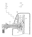
internal antenna 4 and provided to the printedcircuit board 5 via aresilient metal strip 3. The arrows in Fig. 2 indicate a signal flow of the received RF-signal. The metal strip is integrally formed with acontact portion 14 being adapted to provide a switchable electrical connection with a corresponding counter contact portion 41. In the unmated state of the assembly thecontact portion 14 abuts to the counter contact portion 41, which is electrically connected to theinternal antenna 4. Finally, asignal terminal 16 of themetal strip 3 provides the RF-signal to thePCB 5. Reference numbers 27 and 26 indicate the mating sections of the first and second coaxial connectors respectively. - Figure 3 illustrates the arrangement of the coaxial connector assembly or the antenna assembly in the
housing 6 of a mobile phone. The top view illustrates in its cross sectional part theinternal antenna 4 and the firstcoaxial connector 1. Furthermore, in the corresponding cross sectional side view shown in the lower part of Fig. 3, the printedcircuit board 5 as well as a lead in portion 61 of the mobile phone'shousing 6 are illustrated. - Figure 4 shows a more detailed view of the relevant parts of figure 3, wherein the first
coaxial connector 1 comprises theresilient metal strip 3, being mechanically fixed to thefirst connector 1 throughfixing means 42. Theresilient metal strip 3 forms aninner contact 11 of the firstcoaxial connector 1 and preferably has a U-shaped form. Furthermore, it protrudes with its tip 18 from amating face 17 of the firstcoaxial connector 1. Thefirst connector 1 further comprises a non-illustrated ground or outer contact portion at aposition 12 being separated from the inner connector by a dielectric 13. - The
inner contact 11 of theresilient metal strip 3 is movable in an axial direction. Accordingly, the first connector may be adapted to allow a corresponding movement of theinner contact 11 by providing a gap between theinner contact 11 and the dielectric 13. Therein, the gap may also at least partly form the dielectric 13. The firstcoaxial connector 1 further comprises a lead-inportion 29 for guiding and locating the connector mating sections during plugging together. - Preferably, the
inner contact 21 of the second coaxial connector 2 (Fig. 2) has a recess 25 formed in itsmating face 24 to abut or receive the tip 18 of the protruding metal strip in the mated state of the assembly. - As illustrated in figure 1 in the mated state of the connector assembly an
inner contact 21 of thesecond connector 2 comes into contact with the tip 18 of theinner contact 11 of theresilient metal strip 3. The second connector further comprises anouter contact 22 which is separated from itsinner contact 21 by a dielectric 23. In the mated state the respective mating faces of the first and second connector oppose each other. - The
resilient metal strip 3 is at least partly moveable in an axial direction to provide a switching function between a signal from thesecond connector 2 or theinternal antenna 4. Upon mating of the first 1 and second 2 coaxial connector theinner contacts 11 of the resilient metal strip is depressed so as to separate itscontact portion 14 from the counter contact portion 41. Thereby in the mated state of the connector assembly an external RF-signal arriving from the second connector is transferred to thePCB 5 via the resilient metal strip as indicated by the arrows in figure 1. - Preferably the
metal strip 3 has thecontact portion 14 at a free end of afirst contact leg 19 of themetal strip 3. Furthermore, in an advantageous embodiment the contact portion or RFinput signal terminal 16 of the resilient metal strip is embodied at a free end of a resilient second contact leg 15 of themetal strip 3. - Furthermore, the fixing means 7 may be used to clip or screw the antenna assembly to the PCB and may be adapted to provide a flexible mechanical connection the PCB to further improve the mechanical coupling to the connector assembly. Finally, the ground contact or
outer contact 12 of the first connector may be electrically connected to thePCB 5 either by pressing or soldering via the fixing means 7 or with a small spring soldered on thePCB 5. - An antenna assembly according to the invention comprises the first
coaxial connector 1, theantenna portion 4 and theresilient metal strip 3. Therein, essentially theresilient metal strip 3 forms the switching means to provide the switching function in the antenna assembly. As it is apparent for a skilled person the same above-mentioned advantage for the antenna assembly may be achieved with common switching means. The switching means or resilient metal strip has thecontact portion 16 as a common RF input signal terminal. The first coaxial connector is matable with a secondcoaxial connector 2. Depending on a corresponding mated or an unmated state of the antenna assembly, the RF signal is switched to either theantenna portion 4 or thesecond connector 2. - Figure 5 illustrates a second embodiment for the present invention. Since most of the details illustrated therein are identical to the first embodiment basically the differences thereto will be described in more detail.
- The
antenna portion 4 is equally integrally formed with thefirst connector 1, but according to this embodiment mechanically fixed to thehousing 6. Hence, no direct mechanical connection to thePCB 5 exists and corresponding mechanical stress only indirectly effects thePCB 5 by means of thehousing 6. The electrical connection to thePCB 5 again is realised by theresilient metal strip 3 as illustrated for the first embodiment of the invention. A further difference to the first embodiment is the modified lead-inarea 29 of thefirst connector 1, thereby avoiding the need for a lead-in area 61 of thehousing 6. - As will be apparent for a person skilled in the art, the following improvements lead to further preferred embodiments for the first as well as the second embodiment.
- In a modification of the above embodiments, the first
coaxial connector 1 and theantenna portion 4 may be formed as a single molded integrated device. Therein the antenna assembly is essentially formed by one part made out of two different plastic parts wherein one of the plastic parts is covered by a conducting layer e.g. nickel layer, the other plastic part being non-covered. - Moreover, the
contact portion 14 of theresilient metal strip 3 may also be arranged in between the fixed portion thereof and theinner contact 11. The axial movement of theresilient metal strip 3 still would be suitable to separate thecontact portion 14 from the correspondingly arranged counter contact portion 41. Finally, the second coaxial connector may be connected to an external antenna e.g. a car kit or a test probe in a production line.
Claims (7)
- A coaxial connector assembly comprising a first coaxial connector (1) and a second coaxial connector (2) matable therewith in an axial direction, each said connector comprising a mating section (26, 27) having an inner contact (11, 21) surrounded by an outer contact (12, 22) and separated therefrom by a dielectric (13, 23), one of the first and second coaxial connectors having a lead-in portion (29) for guiding and locating the connector mating section of the other of the first and second coaxial connectors during plugging together, characterized in that:said inner contact (11) is formed by a resilient metal strip which is integrally formed with a contact portion (14) that is adapted to provide a switchable electrical connection with a corresponding counter contact portion (41) depending on the mated or unmated state of the coaxial connector assembly.
- The coaxial connector assembly according to claim 1, wherein said inner contact of said resilient metal strip has a U-shaped form.
- The coaxial connector assembly according to claim 1, wherein said resilient metal strip comprises a first contact leg (19) having said contact portion arranged at its free end.
- The coaxial connector assembly according to claim 1, wherein said resilient metal strip has a signal terminal (16) for making an electrical connection to a printed circuit board (5).
- The coaxial connector assembly according to claim 1, wherein said first connector has a mating face (17), and a tip (18) of said metal strip protrudes from the mating face.
- The coaxial connector assembly according to claim 5, wherein said second connector has a mating face (24) and a recess in said mating face to receive the tip of said protruding metal strip in the mated state of the connector assembly.
- The coaxial connector assembly according to claim 1, wherein said first connector comprises fixing means (42) for fixing said resilient metal strip in said first connector.
Applications Claiming Priority (2)
| Application Number | Priority Date | Filing Date | Title |
|---|---|---|---|
| US09/901,432 US6473045B1 (en) | 2001-07-09 | 2001-07-09 | Coaxial connector assembly and antenna assembly having a switching function |
| US901432 | 2001-07-09 |
Publications (3)
| Publication Number | Publication Date |
|---|---|
| EP1278274A2 true EP1278274A2 (en) | 2003-01-22 |
| EP1278274A3 EP1278274A3 (en) | 2003-05-21 |
| EP1278274B1 EP1278274B1 (en) | 2007-09-19 |
Family
ID=25414176
Family Applications (1)
| Application Number | Title | Priority Date | Filing Date |
|---|---|---|---|
| EP02014540A Expired - Lifetime EP1278274B1 (en) | 2001-07-09 | 2002-07-01 | Coaxial connector assembly and antenna assembly having a switching function |
Country Status (6)
| Country | Link |
|---|---|
| US (1) | US6473045B1 (en) |
| EP (1) | EP1278274B1 (en) |
| CN (1) | CN1396789A (en) |
| AT (1) | ATE373882T1 (en) |
| DE (1) | DE60222507T2 (en) |
| DK (1) | DK1278274T3 (en) |
Families Citing this family (18)
| Publication number | Priority date | Publication date | Assignee | Title |
|---|---|---|---|---|
| FR2828022B1 (en) * | 2001-07-27 | 2003-11-21 | Framatome Connectors Int | INTEGRATED ASSEMBLY COMPRISING AN ANTENNA AND A SWITCH |
| FR2841038B1 (en) * | 2002-06-13 | 2004-08-27 | Cit Alcatel | CONNECTOR-SWITCH COMBINATION FOR FLAT ANTENNA |
| US6837724B2 (en) * | 2002-06-27 | 2005-01-04 | Molex Incvorporated | Electrical connector with an internal switch |
| US6683577B1 (en) * | 2002-09-06 | 2004-01-27 | Smartant Telecom Co., Ltd. | Printed circuit antenna |
| US6734832B1 (en) * | 2002-12-13 | 2004-05-11 | Motorola, Inc. | Antenna switching system for a mobile communication device |
| US6940459B2 (en) * | 2002-12-31 | 2005-09-06 | Centurion Wireless Technologies, Inc. | Antenna assembly with electrical connectors |
| JP4162525B2 (en) | 2003-03-28 | 2008-10-08 | 日本圧着端子製造株式会社 | Connector unit for high frequency radio |
| JP2005251746A (en) * | 2004-03-02 | 2005-09-15 | Tyco Electronics Amp Gmbh | Plug socket connector of very small size |
| JP4220446B2 (en) * | 2004-08-27 | 2009-02-04 | ヒロセ電機株式会社 | Coaxial connector with switch |
| US7161544B2 (en) * | 2004-12-29 | 2007-01-09 | Sony Ericsson Mobile Communications | Mobile terminals including a built-in radio frequency test interface |
| US7364458B1 (en) * | 2006-12-20 | 2008-04-29 | Lotes Co., Ltd. | Electrical connector |
| US8068058B2 (en) * | 2007-07-06 | 2011-11-29 | Laird Technologies, Inc. | Antenna assembly with connectors having an internal conductive channel |
| ATE472189T1 (en) | 2008-03-10 | 2010-07-15 | Tyco Electronics Amp Gmbh | COAXIAL CONNECTOR |
| US8172627B2 (en) * | 2008-12-03 | 2012-05-08 | Tyco Electronics Corporation | Electrical connector with plated plug and receptacle |
| ATE540452T1 (en) | 2009-05-29 | 2012-01-15 | Tyco Electronics Nederland Bv | MINIATURE SWITCHING CONNECTORS |
| KR101689601B1 (en) | 2010-05-19 | 2016-12-26 | 엘지전자 주식회사 | Mobile terminal |
| US8899992B2 (en) | 2012-04-09 | 2014-12-02 | Asustek Computer Inc. | Connector |
| KR102208755B1 (en) * | 2014-04-04 | 2021-01-28 | 삼성전자주식회사 | Electronic device |
Citations (4)
| Publication number | Priority date | Publication date | Assignee | Title |
|---|---|---|---|---|
| US5421289A (en) * | 1992-06-12 | 1995-06-06 | Capellaro; Ricky J. | Feed bowl mounting device for pet enclosures with spring loaded detent plunger for quick disconnect and removal of the bowl |
| EP1039588A2 (en) * | 1999-03-25 | 2000-09-27 | Itt Manufacturing Enterprises, Inc. | PCB-mounted switch |
| GB2351617A (en) * | 1999-06-30 | 2001-01-03 | Matsushita Electric Ind Co Ltd | Coaxial connector with switch |
| US6439906B1 (en) * | 1999-03-25 | 2002-08-27 | Itt Manufacturing Enterprises, Inc. | Coax switch assembly |
Family Cites Families (6)
| Publication number | Priority date | Publication date | Assignee | Title |
|---|---|---|---|---|
| JP3251801B2 (en) | 1995-03-03 | 2002-01-28 | ヒロセ電機株式会社 | High frequency switch for board mounting |
| US5516303A (en) * | 1995-01-11 | 1996-05-14 | The Whitaker Corporation | Floating panel-mounted coaxial connector for use with stripline circuit boards |
| GB9700531D0 (en) | 1997-01-13 | 1997-03-05 | Decolletage Sa Saint Maurice | Coaxial switch connector assembly |
| US6224407B1 (en) * | 1997-12-17 | 2001-05-01 | The Whitaker Corporation | Coaxial switch connector assembly |
| JPH11251001A (en) * | 1997-12-22 | 1999-09-17 | Whitaker Corp:The | Coaxial connector assembled body |
| JP3337650B2 (en) * | 1998-10-05 | 2002-10-21 | ヒロセ電機株式会社 | Coaxial connector with switch |
-
2001
- 2001-07-09 US US09/901,432 patent/US6473045B1/en not_active Expired - Fee Related
-
2002
- 2002-07-01 DK DK02014540T patent/DK1278274T3/en active
- 2002-07-01 AT AT02014540T patent/ATE373882T1/en not_active IP Right Cessation
- 2002-07-01 DE DE60222507T patent/DE60222507T2/en not_active Expired - Fee Related
- 2002-07-01 EP EP02014540A patent/EP1278274B1/en not_active Expired - Lifetime
- 2002-07-03 CN CN02140146.2A patent/CN1396789A/en active Pending
Patent Citations (4)
| Publication number | Priority date | Publication date | Assignee | Title |
|---|---|---|---|---|
| US5421289A (en) * | 1992-06-12 | 1995-06-06 | Capellaro; Ricky J. | Feed bowl mounting device for pet enclosures with spring loaded detent plunger for quick disconnect and removal of the bowl |
| EP1039588A2 (en) * | 1999-03-25 | 2000-09-27 | Itt Manufacturing Enterprises, Inc. | PCB-mounted switch |
| US6439906B1 (en) * | 1999-03-25 | 2002-08-27 | Itt Manufacturing Enterprises, Inc. | Coax switch assembly |
| GB2351617A (en) * | 1999-06-30 | 2001-01-03 | Matsushita Electric Ind Co Ltd | Coaxial connector with switch |
Also Published As
| Publication number | Publication date |
|---|---|
| EP1278274A3 (en) | 2003-05-21 |
| CN1396789A (en) | 2003-02-12 |
| US6473045B1 (en) | 2002-10-29 |
| ATE373882T1 (en) | 2007-10-15 |
| DE60222507T2 (en) | 2008-06-26 |
| EP1278274B1 (en) | 2007-09-19 |
| DE60222507D1 (en) | 2007-10-31 |
| DK1278274T3 (en) | 2007-12-10 |
Similar Documents
| Publication | Publication Date | Title |
|---|---|---|
| EP1278274B1 (en) | Coaxial connector assembly and antenna assembly having a switching function | |
| JP3881863B2 (en) | Coaxial connector with switch | |
| US5453019A (en) | Internal/external antenna switch connector | |
| KR100491682B1 (en) | Coaxial Connector with Switch | |
| EP2175531B1 (en) | Coaxial connector | |
| US6224407B1 (en) | Coaxial switch connector assembly | |
| KR101802731B1 (en) | Coaxial connector with switch | |
| JP3422485B2 (en) | Jack | |
| EP0869584B1 (en) | Coaxial connector for switching antennas | |
| JP2010108719A (en) | Connector | |
| WO1998031078A1 (en) | Coaxial switch connector assembly | |
| US6142803A (en) | Coaxial antenna connector for mobile phone | |
| JP5557104B2 (en) | Connector and connection path switching device | |
| JP3079274B2 (en) | Coaxial connector with switch | |
| JP2001035606A (en) | Connector with switch | |
| JPH09147996A (en) | Connector with change-over switch | |
| EP0924810B1 (en) | Coaxial antenna connector for mobile phone | |
| JP2002093533A (en) | Coaxial connector and communication device | |
| JP2004031087A (en) | Coaxial connector with switch | |
| CN215771780U (en) | First connector and connector assembly | |
| EP1041680A2 (en) | Electrostatic discharge protection for a coaxial connector | |
| JP2004047169A (en) | Coaxial connector assembly | |
| KR100511493B1 (en) | Coaxial connector with dual rf switch | |
| KR200332348Y1 (en) | Coaxial connector with dual rf switch | |
| US7435118B2 (en) | Antenna switch |
Legal Events
| Date | Code | Title | Description |
|---|---|---|---|
| PUAI | Public reference made under article 153(3) epc to a published international application that has entered the european phase |
Free format text: ORIGINAL CODE: 0009012 |
|
| AK | Designated contracting states |
Kind code of ref document: A2 Designated state(s): AT BE BG CH CY CZ DE DK EE ES FI FR GB GR IE IT LI LU MC NL PT SE SK TR |
|
| AX | Request for extension of the european patent |
Free format text: AL;LT;LV;MK;RO;SI |
|
| PUAL | Search report despatched |
Free format text: ORIGINAL CODE: 0009013 |
|
| AK | Designated contracting states |
Designated state(s): AT BE BG CH CY CZ DE DK EE ES FI FR GB GR IE IT LI LU MC NL PT SE SK TR |
|
| AX | Request for extension of the european patent |
Extension state: AL LT LV MK RO SI |
|
| 17P | Request for examination filed |
Effective date: 20031121 |
|
| AKX | Designation fees paid |
Designated state(s): AT BE BG CH CY CZ DE DK EE ES FI FR GB GR IE IT LI LU MC NL PT SE SK TR |
|
| 17Q | First examination report despatched |
Effective date: 20040205 |
|
| 17Q | First examination report despatched |
Effective date: 20040205 |
|
| GRAP | Despatch of communication of intention to grant a patent |
Free format text: ORIGINAL CODE: EPIDOSNIGR1 |
|
| GRAS | Grant fee paid |
Free format text: ORIGINAL CODE: EPIDOSNIGR3 |
|
| GRAA | (expected) grant |
Free format text: ORIGINAL CODE: 0009210 |
|
| AK | Designated contracting states |
Kind code of ref document: B1 Designated state(s): AT BE BG CH CY CZ DE DK EE ES FI FR GB GR IE IT LI LU MC NL PT SE SK TR |
|
| REG | Reference to a national code |
Ref country code: GB Ref legal event code: FG4D |
|
| REG | Reference to a national code |
Ref country code: CH Ref legal event code: EP |
|
| REF | Corresponds to: |
Ref document number: 60222507 Country of ref document: DE Date of ref document: 20071031 Kind code of ref document: P |
|
| REG | Reference to a national code |
Ref country code: IE Ref legal event code: FG4D |
|
| REG | Reference to a national code |
Ref country code: SE Ref legal event code: TRGR |
|
| REG | Reference to a national code |
Ref country code: DK Ref legal event code: T3 |
|
| PG25 | Lapsed in a contracting state [announced via postgrant information from national office to epo] |
Ref country code: AT Free format text: LAPSE BECAUSE OF FAILURE TO SUBMIT A TRANSLATION OF THE DESCRIPTION OR TO PAY THE FEE WITHIN THE PRESCRIBED TIME-LIMIT Effective date: 20070919 |
|
| NLV1 | Nl: lapsed or annulled due to failure to fulfill the requirements of art. 29p and 29m of the patents act | ||
| PG25 | Lapsed in a contracting state [announced via postgrant information from national office to epo] |
Ref country code: BE Free format text: LAPSE BECAUSE OF FAILURE TO SUBMIT A TRANSLATION OF THE DESCRIPTION OR TO PAY THE FEE WITHIN THE PRESCRIBED TIME-LIMIT Effective date: 20070919 |
|
| PG25 | Lapsed in a contracting state [announced via postgrant information from national office to epo] |
Ref country code: NL Free format text: LAPSE BECAUSE OF FAILURE TO SUBMIT A TRANSLATION OF THE DESCRIPTION OR TO PAY THE FEE WITHIN THE PRESCRIBED TIME-LIMIT Effective date: 20070919 Ref country code: GR Free format text: LAPSE BECAUSE OF FAILURE TO SUBMIT A TRANSLATION OF THE DESCRIPTION OR TO PAY THE FEE WITHIN THE PRESCRIBED TIME-LIMIT Effective date: 20071220 Ref country code: ES Free format text: LAPSE BECAUSE OF FAILURE TO SUBMIT A TRANSLATION OF THE DESCRIPTION OR TO PAY THE FEE WITHIN THE PRESCRIBED TIME-LIMIT Effective date: 20071230 |
|
| ET | Fr: translation filed | ||
| PG25 | Lapsed in a contracting state [announced via postgrant information from national office to epo] |
Ref country code: SK Free format text: LAPSE BECAUSE OF FAILURE TO SUBMIT A TRANSLATION OF THE DESCRIPTION OR TO PAY THE FEE WITHIN THE PRESCRIBED TIME-LIMIT Effective date: 20070919 Ref country code: CZ Free format text: LAPSE BECAUSE OF FAILURE TO SUBMIT A TRANSLATION OF THE DESCRIPTION OR TO PAY THE FEE WITHIN THE PRESCRIBED TIME-LIMIT Effective date: 20070919 Ref country code: PT Free format text: LAPSE BECAUSE OF FAILURE TO SUBMIT A TRANSLATION OF THE DESCRIPTION OR TO PAY THE FEE WITHIN THE PRESCRIBED TIME-LIMIT Effective date: 20080219 |
|
| PLBE | No opposition filed within time limit |
Free format text: ORIGINAL CODE: 0009261 |
|
| STAA | Information on the status of an ep patent application or granted ep patent |
Free format text: STATUS: NO OPPOSITION FILED WITHIN TIME LIMIT |
|
| 26N | No opposition filed |
Effective date: 20080620 |
|
| REG | Reference to a national code |
Ref country code: CH Ref legal event code: PL |
|
| REG | Reference to a national code |
Ref country code: DK Ref legal event code: EBP |
|
| EUG | Se: european patent has lapsed | ||
| GBPC | Gb: european patent ceased through non-payment of renewal fee |
Effective date: 20080701 |
|
| PG25 | Lapsed in a contracting state [announced via postgrant information from national office to epo] |
Ref country code: MC Free format text: LAPSE BECAUSE OF NON-PAYMENT OF DUE FEES Effective date: 20080731 |
|
| PG25 | Lapsed in a contracting state [announced via postgrant information from national office to epo] |
Ref country code: EE Free format text: LAPSE BECAUSE OF FAILURE TO SUBMIT A TRANSLATION OF THE DESCRIPTION OR TO PAY THE FEE WITHIN THE PRESCRIBED TIME-LIMIT Effective date: 20070919 Ref country code: DE Free format text: LAPSE BECAUSE OF NON-PAYMENT OF DUE FEES Effective date: 20090203 |
|
| REG | Reference to a national code |
Ref country code: FR Ref legal event code: ST Effective date: 20090331 |
|
| PG25 | Lapsed in a contracting state [announced via postgrant information from national office to epo] |
Ref country code: FI Free format text: LAPSE BECAUSE OF NON-PAYMENT OF DUE FEES Effective date: 20080701 |
|
| PG25 | Lapsed in a contracting state [announced via postgrant information from national office to epo] |
Ref country code: LI Free format text: LAPSE BECAUSE OF NON-PAYMENT OF DUE FEES Effective date: 20080731 Ref country code: GB Free format text: LAPSE BECAUSE OF NON-PAYMENT OF DUE FEES Effective date: 20080701 Ref country code: CH Free format text: LAPSE BECAUSE OF NON-PAYMENT OF DUE FEES Effective date: 20080731 |
|
| PG25 | Lapsed in a contracting state [announced via postgrant information from national office to epo] |
Ref country code: CY Free format text: LAPSE BECAUSE OF FAILURE TO SUBMIT A TRANSLATION OF THE DESCRIPTION OR TO PAY THE FEE WITHIN THE PRESCRIBED TIME-LIMIT Effective date: 20070919 Ref country code: IE Free format text: LAPSE BECAUSE OF NON-PAYMENT OF DUE FEES Effective date: 20080701 Ref country code: DK Free format text: LAPSE BECAUSE OF NON-PAYMENT OF DUE FEES Effective date: 20080731 |
|
| PG25 | Lapsed in a contracting state [announced via postgrant information from national office to epo] |
Ref country code: BG Free format text: LAPSE BECAUSE OF FAILURE TO SUBMIT A TRANSLATION OF THE DESCRIPTION OR TO PAY THE FEE WITHIN THE PRESCRIBED TIME-LIMIT Effective date: 20071219 Ref country code: IT Free format text: LAPSE BECAUSE OF NON-PAYMENT OF DUE FEES Effective date: 20080701 Ref country code: FR Free format text: LAPSE BECAUSE OF NON-PAYMENT OF DUE FEES Effective date: 20080731 |
|
| PG25 | Lapsed in a contracting state [announced via postgrant information from national office to epo] |
Ref country code: SE Free format text: LAPSE BECAUSE OF NON-PAYMENT OF DUE FEES Effective date: 20080702 Ref country code: LU Free format text: LAPSE BECAUSE OF NON-PAYMENT OF DUE FEES Effective date: 20080701 |
|
| PG25 | Lapsed in a contracting state [announced via postgrant information from national office to epo] |
Ref country code: TR Free format text: LAPSE BECAUSE OF FAILURE TO SUBMIT A TRANSLATION OF THE DESCRIPTION OR TO PAY THE FEE WITHIN THE PRESCRIBED TIME-LIMIT Effective date: 20070919 |