EP1278259A2 - Fuel cell unit - Google Patents
Fuel cell unit Download PDFInfo
- Publication number
- EP1278259A2 EP1278259A2 EP02015831A EP02015831A EP1278259A2 EP 1278259 A2 EP1278259 A2 EP 1278259A2 EP 02015831 A EP02015831 A EP 02015831A EP 02015831 A EP02015831 A EP 02015831A EP 1278259 A2 EP1278259 A2 EP 1278259A2
- Authority
- EP
- European Patent Office
- Prior art keywords
- gas
- fuel cell
- substrate
- cell unit
- tight
- Prior art date
- Legal status (The legal status is an assumption and is not a legal conclusion. Google has not performed a legal analysis and makes no representation as to the accuracy of the status listed.)
- Granted
Links
- 239000000446 fuel Substances 0.000 title claims abstract description 151
- 239000000758 substrate Substances 0.000 claims abstract description 101
- 239000012530 fluid Substances 0.000 claims description 55
- 239000003792 electrolyte Substances 0.000 claims description 37
- 229910052751 metal Inorganic materials 0.000 claims description 19
- 239000002184 metal Substances 0.000 claims description 19
- 238000003466 welding Methods 0.000 claims description 18
- 238000007789 sealing Methods 0.000 claims description 14
- 150000001875 compounds Chemical class 0.000 claims description 9
- 238000004382 potting Methods 0.000 claims description 9
- 238000005219 brazing Methods 0.000 claims description 4
- 238000003754 machining Methods 0.000 claims 1
- 239000007789 gas Substances 0.000 description 91
- 239000002737 fuel gas Substances 0.000 description 70
- 239000007800 oxidant agent Substances 0.000 description 33
- 230000001590 oxidative effect Effects 0.000 description 26
- 238000004519 manufacturing process Methods 0.000 description 10
- 238000005476 soldering Methods 0.000 description 9
- VNWKTOKETHGBQD-UHFFFAOYSA-N methane Chemical compound C VNWKTOKETHGBQD-UHFFFAOYSA-N 0.000 description 8
- 230000008093 supporting effect Effects 0.000 description 8
- 238000000034 method Methods 0.000 description 6
- 230000008569 process Effects 0.000 description 6
- 229910000679 solder Inorganic materials 0.000 description 6
- 238000005452 bending Methods 0.000 description 5
- 238000003825 pressing Methods 0.000 description 5
- 239000004215 Carbon black (E152) Substances 0.000 description 4
- 229930195733 hydrocarbon Natural products 0.000 description 4
- 150000002430 hydrocarbons Chemical class 0.000 description 4
- 239000001301 oxygen Substances 0.000 description 4
- 229910052760 oxygen Inorganic materials 0.000 description 4
- -1 oxygen ions Chemical class 0.000 description 4
- MYMOFIZGZYHOMD-UHFFFAOYSA-N Dioxygen Chemical compound O=O MYMOFIZGZYHOMD-UHFFFAOYSA-N 0.000 description 3
- 229910010293 ceramic material Inorganic materials 0.000 description 3
- 239000007769 metal material Substances 0.000 description 3
- XLYOFNOQVPJJNP-UHFFFAOYSA-N water Substances O XLYOFNOQVPJJNP-UHFFFAOYSA-N 0.000 description 3
- UFHFLCQGNIYNRP-UHFFFAOYSA-N Hydrogen Chemical compound [H][H] UFHFLCQGNIYNRP-UHFFFAOYSA-N 0.000 description 2
- XEEYBQQBJWHFJM-UHFFFAOYSA-N Iron Chemical compound [Fe] XEEYBQQBJWHFJM-UHFFFAOYSA-N 0.000 description 2
- 230000004888 barrier function Effects 0.000 description 2
- 238000006243 chemical reaction Methods 0.000 description 2
- 239000011248 coating agent Substances 0.000 description 2
- 238000000576 coating method Methods 0.000 description 2
- 239000000567 combustion gas Substances 0.000 description 2
- 238000010894 electron beam technology Methods 0.000 description 2
- 238000004049 embossing Methods 0.000 description 2
- 239000001257 hydrogen Substances 0.000 description 2
- 229910052739 hydrogen Inorganic materials 0.000 description 2
- 239000000203 mixture Substances 0.000 description 2
- 239000003345 natural gas Substances 0.000 description 2
- 239000011148 porous material Substances 0.000 description 2
- 239000000047 product Substances 0.000 description 2
- 239000007787 solid Substances 0.000 description 2
- 229910018072 Al 2 O 3 Inorganic materials 0.000 description 1
- ODINCKMPIJJUCX-UHFFFAOYSA-N Calcium oxide Chemical compound [Ca]=O ODINCKMPIJJUCX-UHFFFAOYSA-N 0.000 description 1
- VYPSYNLAJGMNEJ-UHFFFAOYSA-N Silicium dioxide Chemical compound O=[Si]=O VYPSYNLAJGMNEJ-UHFFFAOYSA-N 0.000 description 1
- 229910000831 Steel Inorganic materials 0.000 description 1
- 230000009471 action Effects 0.000 description 1
- QVQLCTNNEUAWMS-UHFFFAOYSA-N barium oxide Chemical compound [Ba]=O QVQLCTNNEUAWMS-UHFFFAOYSA-N 0.000 description 1
- 229910052810 boron oxide Inorganic materials 0.000 description 1
- 239000003990 capacitor Substances 0.000 description 1
- 239000000919 ceramic Substances 0.000 description 1
- 239000011195 cermet Substances 0.000 description 1
- 239000007795 chemical reaction product Substances 0.000 description 1
- 238000002485 combustion reaction Methods 0.000 description 1
- 239000002131 composite material Substances 0.000 description 1
- 238000007906 compression Methods 0.000 description 1
- 238000010276 construction Methods 0.000 description 1
- 238000005520 cutting process Methods 0.000 description 1
- 238000000280 densification Methods 0.000 description 1
- JKWMSGQKBLHBQQ-UHFFFAOYSA-N diboron trioxide Chemical compound O=BOB=O JKWMSGQKBLHBQQ-UHFFFAOYSA-N 0.000 description 1
- 238000003487 electrochemical reaction Methods 0.000 description 1
- 239000003502 gasoline Substances 0.000 description 1
- 229910052742 iron Inorganic materials 0.000 description 1
- 239000002923 metal particle Substances 0.000 description 1
- 239000010445 mica Substances 0.000 description 1
- 229910052618 mica group Inorganic materials 0.000 description 1
- 230000003647 oxidation Effects 0.000 description 1
- 238000007254 oxidation reaction Methods 0.000 description 1
- TWNQGVIAIRXVLR-UHFFFAOYSA-N oxo(oxoalumanyloxy)alumane Chemical compound O=[Al]O[Al]=O TWNQGVIAIRXVLR-UHFFFAOYSA-N 0.000 description 1
- 125000004430 oxygen atom Chemical group O* 0.000 description 1
- 230000035699 permeability Effects 0.000 description 1
- 229910052628 phlogopite Inorganic materials 0.000 description 1
- 238000007750 plasma spraying Methods 0.000 description 1
- 238000004080 punching Methods 0.000 description 1
- 238000007650 screen-printing Methods 0.000 description 1
- 238000000926 separation method Methods 0.000 description 1
- 239000007784 solid electrolyte Substances 0.000 description 1
- 229910002076 stabilized zirconia Inorganic materials 0.000 description 1
- 239000010959 steel Substances 0.000 description 1
Images


Classifications
-
- H—ELECTRICITY
- H01—ELECTRIC ELEMENTS
- H01M—PROCESSES OR MEANS, e.g. BATTERIES, FOR THE DIRECT CONVERSION OF CHEMICAL ENERGY INTO ELECTRICAL ENERGY
- H01M8/00—Fuel cells; Manufacture thereof
- H01M8/24—Grouping of fuel cells, e.g. stacking of fuel cells
- H01M8/2465—Details of groupings of fuel cells
- H01M8/247—Arrangements for tightening a stack, for accommodation of a stack in a tank or for assembling different tanks
-
- H—ELECTRICITY
- H01—ELECTRIC ELEMENTS
- H01M—PROCESSES OR MEANS, e.g. BATTERIES, FOR THE DIRECT CONVERSION OF CHEMICAL ENERGY INTO ELECTRICAL ENERGY
- H01M8/00—Fuel cells; Manufacture thereof
- H01M8/02—Details
- H01M8/0271—Sealing or supporting means around electrodes, matrices or membranes
-
- H—ELECTRICITY
- H01—ELECTRIC ELEMENTS
- H01M—PROCESSES OR MEANS, e.g. BATTERIES, FOR THE DIRECT CONVERSION OF CHEMICAL ENERGY INTO ELECTRICAL ENERGY
- H01M8/00—Fuel cells; Manufacture thereof
- H01M8/02—Details
- H01M8/0271—Sealing or supporting means around electrodes, matrices or membranes
- H01M8/0273—Sealing or supporting means around electrodes, matrices or membranes with sealing or supporting means in the form of a frame
-
- H—ELECTRICITY
- H01—ELECTRIC ELEMENTS
- H01M—PROCESSES OR MEANS, e.g. BATTERIES, FOR THE DIRECT CONVERSION OF CHEMICAL ENERGY INTO ELECTRICAL ENERGY
- H01M8/00—Fuel cells; Manufacture thereof
- H01M8/24—Grouping of fuel cells, e.g. stacking of fuel cells
- H01M8/241—Grouping of fuel cells, e.g. stacking of fuel cells with solid or matrix-supported electrolytes
- H01M8/2425—High-temperature cells with solid electrolytes
- H01M8/2432—Grouping of unit cells of planar configuration
-
- H—ELECTRICITY
- H01—ELECTRIC ELEMENTS
- H01M—PROCESSES OR MEANS, e.g. BATTERIES, FOR THE DIRECT CONVERSION OF CHEMICAL ENERGY INTO ELECTRICAL ENERGY
- H01M8/00—Fuel cells; Manufacture thereof
- H01M8/24—Grouping of fuel cells, e.g. stacking of fuel cells
- H01M8/2457—Grouping of fuel cells, e.g. stacking of fuel cells with both reactants being gaseous or vaporised
-
- H—ELECTRICITY
- H01—ELECTRIC ELEMENTS
- H01M—PROCESSES OR MEANS, e.g. BATTERIES, FOR THE DIRECT CONVERSION OF CHEMICAL ENERGY INTO ELECTRICAL ENERGY
- H01M8/00—Fuel cells; Manufacture thereof
- H01M8/24—Grouping of fuel cells, e.g. stacking of fuel cells
- H01M8/2465—Details of groupings of fuel cells
- H01M8/2483—Details of groupings of fuel cells characterised by internal manifolds
-
- H—ELECTRICITY
- H01—ELECTRIC ELEMENTS
- H01M—PROCESSES OR MEANS, e.g. BATTERIES, FOR THE DIRECT CONVERSION OF CHEMICAL ENERGY INTO ELECTRICAL ENERGY
- H01M8/00—Fuel cells; Manufacture thereof
- H01M8/10—Fuel cells with solid electrolytes
- H01M8/12—Fuel cells with solid electrolytes operating at high temperature, e.g. with stabilised ZrO2 electrolyte
- H01M2008/1293—Fuel cells with solid oxide electrolytes
-
- Y—GENERAL TAGGING OF NEW TECHNOLOGICAL DEVELOPMENTS; GENERAL TAGGING OF CROSS-SECTIONAL TECHNOLOGIES SPANNING OVER SEVERAL SECTIONS OF THE IPC; TECHNICAL SUBJECTS COVERED BY FORMER USPC CROSS-REFERENCE ART COLLECTIONS [XRACs] AND DIGESTS
- Y02—TECHNOLOGIES OR APPLICATIONS FOR MITIGATION OR ADAPTATION AGAINST CLIMATE CHANGE
- Y02E—REDUCTION OF GREENHOUSE GAS [GHG] EMISSIONS, RELATED TO ENERGY GENERATION, TRANSMISSION OR DISTRIBUTION
- Y02E60/00—Enabling technologies; Technologies with a potential or indirect contribution to GHG emissions mitigation
- Y02E60/30—Hydrogen technology
- Y02E60/50—Fuel cells
Definitions
- the present invention relates to a fuel cell unit comprising a housing, a substrate and one disposed on an electrode side of the substrate Electrode, wherein the substrate is formed so that it Passage of a gas from a arranged on a gas space side of the substrate Gas space allowed to the electrode.
- the electrode disposed on the electrode side of the substrate forms a Component of a cathode-anode-electrolyte unit, in which in operation the fuel cell unit is an electrochemical reaction takes place in the Course at the anode of the KAE unit electrons are released and this the cathode of the KAE unit for the ionization of oxygen atoms via a external circuit are supplied.
- contact plates serve the charge balance between the cathode of a fuel cell unit and the anode of the adjacent fuel cell unit to the Cathode to supply the electrons required for ionization. From marginal Contact plates of the fuel cell block assembly can electrical Charges are tapped to give them an external utility power circuit supply.
- a difficult problem in the production of such fuel cell units consists in creating a gas-tight seal between the on the Gas space side of the substrate arranged gas space, for example a Brenngasraum, and one of the side facing away from the substrate on the Electrode arranged further gas space, such as an oxidant space.
- the present invention is therefore based on the object, a fuel cell unit to create the type mentioned, in which the on the Gas space side of the substrate arranged gas space in a simple and reliable Way is compared to another gas space sealed gas-tight.
- the Substrate comprises a substantially gas-tight zone, which differs from a Surface of the substrate through the substrate to an opposite Surface of the substrate extends.
- the solution according to the invention is thus based on the concept of a subarea the otherwise gas-permeable substrate in such a way that he forms a substantially gastight barrier, which as part of the on the gas space side of the substrate arranged gas space of another Gas chamber can serve separating seal.
- the gas-tight zone of the substrate gas-tight to the housing of the fuel cell unit borders. In this way, can on an additional sealing element be omitted, otherwise a sealing gap between the substrate and the Seal the housing would have.
- the housing comprises a sheet metal part and that the gas-tight zone of the substrate is adjacent to the sheet metal part.
- a sheet metal part can by one or more forming operations, in particular by embossing and / or deep drawing, from a substantially flat sheet metal blank are produced. This manufacturing process is inexpensive and suitable for mass production.
- the sheet metal part can, for example, a fluid guide element of the fuel cell unit form, which is the leadership of a fuel gas or a gaseous oxidant through the fuel cell unit is used.
- the housing includes machined housing parts.
- the gas-tight zone of the substrate additionally fulfills a sealing function a mechanical holding function, if it is advantageously provided that the gas-tight zone of the substrate is fixed to the housing.
- the gas-tight zone of the substrate by welding, preferably by laser welding, and / or by soldering, preferably by brazing, to the housing is.
- the gas-tight zone of the substrate during the process welding and / or soldering to the housing becomes.
- the fuel cell unit arranged one above the electrode comprises substantially gas-tight electrolyte and that the gas-tight Zone of the substrate on its opposite side of the housing gas-tight adjacent to the electrolyte.
- the electrolyte meets except his electrochemical function as part of the KAE unit additionally one Sealing function, so that on an additional sealing element on the housing opposite side of the substrate can be dispensed with what simplifies the production of the fuel cell unit.
- the fuel cell unit a Sealing region comprises a potting compound, which both to the up to the gas-tight zone of the substrate extending electrolyte as well as the substrate is gas-tight adjacent and thus the outer edge of the electrolyte gas-tight covered.
- Such a potting compound for example, a glass solder, a Metallot or an inorganic paste during the manufacture of the fuel cell unit or hardens during operation of the fuel cell unit.
- a glass solder which can be used as potting compound can be composed, for example, like a glass solder known from EP 0 907 215 A1, ie 11 to 13% by weight aluminum oxide (Al 2 O 3 ), 10 to 14% by weight boron oxide (BO 2 ), approximately 5 % By weight of calcium oxide (CaO), 23 to 26% by weight of barium oxide (BaO) and about 50% by weight of silica (SiO 2 ).
- the fuel cell unit a substantially gas-tight over the electrode arranged Electrolyte includes and that the fuel cell unit further comprises a sealing area which gas-tight to the electrolyte and gas-tight to the gas-tight zone of the substrate on the housing opposite Side adjacent.
- such a sealing region may be substantially gas-tight Potting compound, such as a glass solder, a Metallot or a while the production or during the operation of the fuel cell unit curing include inorganic paste.
- the production of the gas-tight zone in the substrate is greatly facilitated, when the gas-tight zone is formed in a pre-compressed area of the substrate is.
- Such a region has a reduced porosity, so that the still existing pores and through channels in a simple manner, for example by welding or soldering, can be closed.
- the gas-tight zone is preferably annular closed trained.
- the gas-tight zone of the substrate encloses a gas-permeable region of the substrate.
- the gas-tight zone substantially extends parallel to an edge of the substrate and preferably close the edge of the substrate is arranged.
- the construction according to the invention of a fuel cell unit is particularly suitable for so-called high-temperature fuel cell units, the one Operating temperature of up to 1000 ° C and without external reformer directly with a hydrocarbon fuel gas such as Methane or natural gas or, alternatively, using an external Reformers, with a hydrocarbon fuel gas, such as Methane, natural gas, diesel or gasoline fuel, can be operated.
- a hydrocarbon fuel gas such as Methane or natural gas
- a hydrocarbon fuel gas such as Methane, natural gas, diesel or gasoline fuel
- Claim 15 is directed to a fuel cell block assembly, which a Comprises a plurality of fuel cell units according to the invention, the longitudinal follow each other in a stacking direction.
- a fuel cell device shown as a whole as 100 in FIGS. 1 to 12 comprises a substantially cuboid housing 102 (see FIG. 1), into which an oxidant supply line 104 opens, via the the interior of the housing 102, an oxidizing agent, for example Air or pure oxygen from a feed fan (not shown) supplied under an overpressure of, for example, about 50 mbar becomes.
- an oxidizing agent for example Air or pure oxygen from a feed fan (not shown) supplied under an overpressure of, for example, about 50 mbar becomes.
- an oxidant discharge pipe 105 opens, by which excess oxidizing agent from the interior of the housing 102 is dischargeable.
- Fuel cell block assembly 106 which has a lower End plate 108, a middle upper end plate 110, two side upper end plates 111 and a plurality between the lower end plate 108 and the upper end plates 110, 111 arranged along a stacking direction 112nd comprising successive fuel cell units 114.
- Fuel cell units 114 includes each of the fuel cell units 114 is a substantially plate-shaped cathode-anode-electrolyte unit 116 (hereinafter referred to briefly as KAE unit), between a contact plate 118 and a fluid guide frame 120 is held.
- KAE unit substantially plate-shaped cathode-anode-electrolyte unit
- the KAE unit 116 includes, as shown purely schematically in Fig. 4, a gas-permeable, electrically conductive substrate 121, for example, as Metal wire mesh, metal wire mesh, metal wire mesh, metal wire mesh or as a porous or sintered metal particle Body may be formed, wherein through the substrate 121, a fuel gas pass from a fuel gas space 124 adjacent to the substrate 121 can.
- a gas-permeable, electrically conductive substrate 121 for example, as Metal wire mesh, metal wire mesh, metal wire mesh, metal wire mesh or as a porous or sintered metal particle Body may be formed, wherein through the substrate 121, a fuel gas pass from a fuel gas space 124 adjacent to the substrate 121 can.
- the KAE unit 116 includes a substrate 121 disposed on the plate-shaped anode 122 of an electrically conductive ceramic material, such as Ni-ZrO 2 cermet (ceramic-metal mixture), which is porous to the fuel gas from the fuel gas chamber 124 the Passage through the anode 122 to allow the electrolyte 126 adjacent to the anode 122.
- an electrically conductive ceramic material such as Ni-ZrO 2 cermet (ceramic-metal mixture)
- a fuel gas for example, a hydrocarbon-containing gas mixture or pure hydrogen can be used.
- the electrolyte 126 is preferably formed as a solid electrolyte us, for example formed from yttrium-stabilized zirconia.
- an oxidizing agent such as air or pure oxygen
- the electrolyte 126 is substantially gas tight, so that no oxidizing agent from the oxidant space 130 through the electrolyte 126 into the fuel gas space 124 and no fuel gas from the fuel gas chamber 124 through the Electrolyte 126 can enter the oxidant space 130.
- the KAE unit 116 has each one Fuel cell unit 114 a temperature of, for example, about 850 ° C, at which the electrolyte 126 is conductive for oxygen ions.
- the Oxidant from the oxidant space 130 increases at the anode 122 Electrons and gives divalent oxygen ions to the electrolyte 126th which migrate through the electrolyte 126 to the anode 122.
- the fuel gas from the fuel gas chamber 124 through the Oxygen ions from the electrolyte 126 oxidize and thereby give electrons to the anode 122 from.
- the contact plates 118 are used in the reaction of the anode 122nd dissipating electrons from the anode 122 via the substrate 121 to dissipate or the electrons required for the reaction at the cathode 128 To supply cathode 128.
- each of the contact plates 118 made of a good electrical conductivity Sheet metal, which (as best seen in Fig. 5 can be seen) with a variety is provided by contact elements 132, which, for example, the shape in the longitudinal direction 133 of the contact plate 118 extending ribs which follow one another in the transverse direction 131 of the contact plate 118, wherein the successive in the transverse direction 131 contact elements 132 directly adjacent to each other and from the center plane 139 of the contact plate 118 from alternately to different sides of the contact plate 118 project.
- Each of the contact elements 132 has a central, strip-shaped contact region 137 at which it is connected to an adjacent KAE unit 116 in FIG electrically conductive contact is (see in particular Fig. 4 and Fig. 7).
- the contact areas 137 of the anode-side contact elements 132 a of a Contact plate 118 are connected to the substrate 121 and thus to the anode 122 the same fuel cell unit 114 associated KAE unit 116 in electrical surface contact, so that electrons from the respective anode 122nd can get into the contact plate 118.
- the cathode-side contact elements 132b of the contact plates 118 stand each with the cathode 128 of an adjacent fuel cell unit 114 associated KAE unit 116 in electrically conductive surface contact, so that electrons can pass from the contact plate 118 to the cathode 128. In this way, the contact plates 118 allow the charge balance between the anodes 122 and the cathodes 128 along the stacking direction 112 consecutive KAE units 116.
- the arranged at the ends of the fuel cell block assembly 106 contact plates 118 are (in a non-illustrated way) with an external one Circuit connected to the at these marginal contact plates 118 tap resulting electric charges.
- each contact plate 118 has the structure of one in the transverse direction 131 of the contact plate 118 corrugated corrugated iron on.
- the gas guide region 136 has on both sides of the contact pad 134 respectively a side area 140a and 140b, respectively.
- a plurality for example two, are substantially circular fuel gas passage openings 142 formed.
- Each of the fuel gas passage openings 142 is of an annular edge region 144, each of the regions 142 opposite the gas guide region 136 offset along the stacking direction 112 down and with the gas guide region 136 via a slope 146, which at an inner Bend line 148 to the respective edge region 144 and along an outer Bend line 150 adjacent to the gas guide region 136, is connected.
- the fuel gas passage openings 142 serve for the passage of the fuel cell units 114 zu formatdem fuel gas through the respective contact plate 118th
- each Contact plate 118 is a plurality of, for example, three substantially circular exhaust gas passage openings 152 provided.
- Each of the exhaust gas passage openings 152 is of an annular edge region 154 surrounded, which opposite the gas guide region 136 of Contact plate 118 along the stacking direction 112 is offset downward and with the gas guide region 136 via a slope 156, which at an inner Bend line 158 to the edge region 154 and along an outer bend line 160 adjacent to the gas guide area 136, with the gas guide area 136 is connected (see in particular Fig. 8).
- the exhaust gas passage openings 152 of the contact plate 118 allow the Passage of exhaust gas to be discharged from the fuel cell units 114, which excess fuel gas and combustion products, in particular Water contains, through the contact plate 118th
- each contact plate 118 encloses a gas guide region 136
- the outer edge of the edge region 162 is connected to a connecting flange 170 provided which adjoins the edge region 162 along a bending line 172 and extending from the edge region 162 substantially parallel to the stacking direction 112 extends down.
- connection flange 170 The substantially parallel to the stacking direction 112 aligned outer surface of the connection flange 170 forms a first connection surface 174.
- Each of the contact plates 118 is formed as a sheet metal part, which consists of a substantially planar, substantially rectangular sheet metal layer Embossing and / or deep drawing as well as by punching out or cutting out the Fuel gas passage openings 142 and the exhaust gas passage openings 152 is formed.
- the fluid guide frame 120 are as sheet metal parts of a substantially levels, formed substantially rectangular sheet metal layer.
- each fluid guide frame 120 a substantially rectangular, central passage opening 176 for the Passage of the KAE unit 116 of the same fuel cell unit 114.
- This passage opening 176 is of a substantially planar, vertical Surrounding the stacking direction 112 gas guide area 178 surrounded, which two side portions 180a, 180b, which at the passage opening 176 opposite.
- substantially circular exhaust passage openings 184 are formed, which the passage of exhaust gas to be discharged from the fuel cell units 114 allow the fluid guide frame 120.
- each fluid guide frame 120 is at its outer edge provided with a connecting flange 186 which longitudinally a bend line 188 adjacent to the gas guide region 178 and from the gas guide region 178 substantially parallel to the stacking direction 112 extends down.
- the substantially parallel to the stacking direction 112 aligned inside of the connecting flange 186 forms a second connecting surface 190.
- a fluid guide frame 120 and a contact plate 118 together a housing 192 of a fuel cell unit 114.
- the substantially aligned parallel to the stacking direction 112 surrounds Connecting flange 186 of the fluid guide frame 120 which also in essentially aligned parallel to the stacking direction 112 connecting flange 170 of the contact plate 118 such that the first connection surface the connection flange 170 of the contact plate 118 and the second connection surface 190 on the connecting flange 186 of the fluid guiding frame 120 facing each other.
- the weld 196 may, for example, in the laser welding process or in Electron beam process can be produced.
- connection between the connecting flanges 186 and 170 also by soldering, in particular by a brazing done.
- the contact plate 118 in a kind Slidable seat received in the fluid guide frame 120, so that the connecting flanges 186 and 170 then also easily gastight with each other can be connected when the distance between the lower edges 194 and 198 along the stacking direction 112 due to manufacturing tolerances in the manufacture of the contact plate 118 and the fluid guide frame 120 or due to mounting tolerances in the assembly of the fuel cell unit 114 along the edge of the contact plate 118 and the edge of the Fluid guide frame 120 varies.
- annular support members 200 which with its bottom 202 each at the top of an exhaust passage opening 152 surrounding edge portion 154 of a contact plate 118 and with its top 204 each at the bottom of an exhaust passage opening 184 in the fluid guide frame 120 surrounding area of Fluid guide frame 120 abut.
- Such a support element 200 is shown in perspective in Fig. 10 and has the shape of a circular ring with a substantially rectangular Cross-section on.
- Supporting element 200 with radially aligned, the support element 200 of the inside 206 of which passes through to the outside 208, in the Circumferential direction of the support member 200 spaced from each other, in essential cylindrical gas passageways 210 provided.
- the support members 200 serve to the contact plate 118 and the fluid guide frame 120 of a housing 192 of a fuel cell unit 114 Keep distance from each other and so squeezing the case 192 by the during assembly of the fuel cell block assembly 106 on the Housing 192 acting clamping force to prevent.
- the supporting action of the support members 200 plays a particular role in the operating temperature of the fuel cell device 100, which is in a range of about 800 ° C to about 1000 ° C in a high-temperature fuel cell device, since at such operating temperatures, the yield strength of the steel from which the contact plate 118 and the fluid guide frame 120 are reduced to values of less than about 10 N / mm 2 , so that even without the presence of the support members 200 even small clamping forces would be sufficient to press the contact plate 118 and the fluid guide frame 120 of a housing 192 against each other.
- the support members 200 may be made of a metallic material or be formed of a ceramic material.
- a support element can be used, which as a porous sintered element formed of a ceramic and / or a metallic material is. Such a sintered element already has a porosity sufficient gas permeability, so that such an element not with Gas passageways must be provided.
- Each of the gas canister 212 seals the gap between the adjacent contact plate 118 and the adjacent fluid guide frame 120 from gas-tight and surrounds the respective exhaust gas passage opening 152, 184 in the contact plate 118 and in the fluid guide frame 120 annular.
- the gas channel seals 112 may each be a flat gasket of mica, in particular of phlogopite.
- gas channel seals 212 each a gas-tight, electrically insulating coating comprising, as a paste by screen printing or by roll coating on the surface of the contact plate 118 or on the surface of the Fluid guide frame 120 is applied.
- each fuel cell unit 114 is of the Oxidant space 130 of one arranged in the stacking direction 112 above Fuel cell unit 114 gas-tight by a fuel gas space seal 218 separated, their structure in the following with reference to Figure 11 is described in detail.
- the substrate 121 has the KAE unit 116 a densified outer area 220 extending along the entire circumference of the substrate 121 and in which the thickness of the substrate 121 by pressing for example to about 20% of the initial thickness, i.e. the thickness of the unpressed portion of the substrate 121 has been reduced is.
- the porosity of the substrate 121 i. of the percentage of gas filled volume of the substrate 121 on the total volume of the substrate 121, in the compacted outer region 220 at nearly Zero reduced.
- a substrate 121 having a porosity of x% has the thickness in the compressed outer region 220 by the compression process preferably reduced to (100 - x)% of the initial thickness; in the Case of porosity from 80% to 20% of the initial thickness.
- the substrate 121 is connected to the underside 222 of the compacted outer area 220 placed on the fluid guide frame 120 and by a welding process, for example by laser welding, electron beam welding, Projection welding or capacitor discharge welding, gas-tight with the metallic material of the fluid guide frame 120 connected.
- a welding process for example by laser welding, electron beam welding, Projection welding or capacitor discharge welding, gas-tight with the metallic material of the fluid guide frame 120 connected.
- the welding process is in the compacted outer region 220 of the Substrate 121 has a porosity-less gas-tight zone 224, which extends from the bottom 222 to the top 226 of the compacted Outside area 220 through the compacted outer area 220 of Substrate 121 extends therethrough and along the entire circumference forming the substrate 121 extending gas-tight barrier, which passes through a gas from the outside of the gas-tight zone 224 lying edge region 228 in the enclosed by the gas-tight zone 224 inner region 230 of Substrate 121 as well as prevents gas passage in the reverse direction.
- the gas-tight zone 224 in the compressed outer region 220 of the Substrate 221 also by soldering the substrate 121 to the fluid guide frame 120 are formed.
- the solder used is due to the capillary action into the remaining pores and through channels in the densified outer region 220 of the substrate 121 is sucked in and closes these passageways permanently, so that one over the entire Height of the compressed outer region 220 extending gas-tight zone 224 is created.
- the gas-tight electrolyte extends 126 of the KAE unit 116 over the edge of the gas-permeable anode 122 and beyond the edge of the gas-permeable cathode 128 and lies with his Bottom side directly on the top 226 of the compacted outer area 220 of the substrate 121.
- the outer region 232 of the electrolyte 126 thus forms together with the gas tight zone 224 of the compacted outer region 220 of the substrate 121 a gas-tight fuel gas space seal 218, which the above the fluid guide frame 120 arranged oxidant space 130 gas-tight from the fuel gas space disposed below the fluid guide frame 120 124 separates.
- this seal is in the area between the outer edge of the anode 122 and the gas-tight zone 224 of the compressed outer region 220 of the Substrate 121 through the out past the anode 122 outdoor area 232 of the electrolyte 126 is formed.
- the fuel gas space seal 218 a sealing region formed from a potting compound comprising the area from the outer edge of the anode 122 up to the gas-tight zone 224 gas-tight covered.
- Such a potting compound for example, a glass solder, a Metallot or an inorganic paste.
- the KAE unit 116 rests with the compacted outer portion 220 of FIG Substrate 121 on the fluid guide frame 120 of the same fuel cell unit 114, wherein the uncompressed region of the substrate 121 by the passage opening 176 of the fluid guide frame 120 extends therethrough, the substrate 121 by welding or soldering to the fluid guide frame 120 is fixed and the fluid guide frame 120 by welding at the weld 196 or by soldering its connecting flange 186 with the connecting flange 170 of the contact plate 118 at the contact plate 118 is fixed.
- the fuel cell units 114 of the fuel cell stack 106 are along the stacking direction 112 stacked so that the cathode side Contact elements 132b of each contact plate 118 to the cathode of KAE unit 116 of the underlying fuel cell unit 114 extend and abut in the electrically conductive contact on the same.
- the fuel gas passage openings 142, 182 and the exhaust gas passage openings are aligned 152, 184 along the stacking direction 112 successively Fuel cell units 114 with each other, so as to the fuel gas channels 216 and the exhaust ducts 214 to form.
- each fuel gas channel 216 opens at the lower end of each fuel gas channel 216 in the same a fuel gas supply port 234, which is the lower End plate 108 of the fuel cell block assembly 106 coaxial with the respective Fuel gas passage 216 interspersed.
- a fuel gas branch line 236 is connected, which from a fuel gas supply line 238 branches off, passing through the housing of the Fuel cell device 100 passed gas-tight and to a (not shown) fuel gas supply is connected, which the fuel gas supply line 238 a fuel gas, for example a hydrocarbon-containing gas or pure hydrogen under an overpressure of, for example, about 50 mbar feeds.
- a fuel gas for example a hydrocarbon-containing gas or pure hydrogen under an overpressure of, for example, about 50 mbar feeds.
- the exhaust channels 214 of the fuel cell block assembly 106 open at their upper ends in each case in a respective exhaust passage 214 coaxial Abgasabriosö réelle 240 (see FIG. 3), which the lateral upper end plate 111 interspersed and at their end facing away from the respective exhaust duct 214 end is connected to a respective exhaust branch line 242.
- exhaust branch lines 242 lead into a common exhaust gas discharge line 244 (see Fig. 1), which gas-tight through the housing 102 of the fuel cell device 100 passed and to a (not shown) exhaust treatment unit connected.
- the fuel gas flows through the Fuel gas supply pipe 238, the fuel gas branch pipes 236 and the fuel gas supply ports 234 in the two fuel gas channels 216 and distributed from there through the gas passageways 210 of the combustion gas channel side support elements 200 to the fuel gas chambers 124 of the fuel cell units 114, which respectively through the contact plate 118, the fluid guide frame 120 and the KAE unit 116 of the respective fuel cell unit 114 enclosed are.
- the fuel gas is at least partially at the respective fuel gas chamber 124 limiting anode 122 of the respective KAE unit 116 oxidized.
- the oxidation product gets along with excess Fuel gas from the fuel gas chambers 124 of the fuel cell units 114th through the gas passageways 210 of the abgaskanalassien supporting elements 200 in the three exhaust passages 214, from which it through the Abgasab adoptedö réelleen 240, the exhaust branch lines 242 and the exhaust gas discharge line 244 is discharged to the (not shown) exhaust treatment unit.
- the oxidant needed for operation of the fuel cell device 100 (For example, air or pure oxygen) is the interior of the Housing 102 is supplied through the oxidant supply line 104.
- oxygen ions formed by the electrolytes 126 to the anodes 122 of the KAE units 116 of the fuel cell units 114 migrate.
- the flow direction of the fuel gas and the exhaust gas through the fuel cell device 100 is in the drawings with simple arrows 246, the Flow direction of the oxidant through the fuel cell device 100 indicated by double arrows 248.
- the flow direction of the oxidant through the oxidant spaces 130 is substantially parallel to the flow direction of the fuel gas through the fuel gas chambers 124.
- Connecting screws 250 are provided, which Through holes 252 in the middle upper end plate 110 of the fuel cell block assembly 106 enforce and at their respective Screw head 254 opposite end provided with an external thread 256 are, which in each case a threaded bore 258 in the lower end plate 108 of the fuel cell assembly 106 is screwed so that the middle upper end plate 110 and lower end plate 108 through the connecting bolts 250 are braced against each other and a desired pressing force via the end plates 108, 110 on the central, the contact pads 134th comprehensive range of the stack of fuel cell units 114 transferable is (see Fig. 2).
- a plurality of connecting bolts 260 are provided, which through-holes 262 in the side upper end plates 111 of the fuel cell block assembly 106 enforce and at her the respective screw head 264 opposite end are provided with an external thread 266, which is screwed into a respective threaded bore 268 in the lower end plate 108 is such that the lateral upper end plates 111 and the lower end plate 108 are braced against each other by the connecting screws 260 and a desired pressing force over the end plates 108, 111 in the region of Fuel gas channels 216 and the exhaust ports 214 to the stack of fuel cell units 114 is transferable.
- the by the external tension by means of the connecting screws 250 and the middle upper end plate 110 generated pressing force determines the contact pressure, with which the contact elements 132 against the substrate 121 or against the cathode 128 of the adjacent KAE unit 116 are pressed.
- the fuel cell block assembly 106 described above becomes as follows assembled:
- the individual fuel cell units 114 are assembled by each a substrate 121 with its compacted outer region 220 on a Fluid guide frame 120 launched and described in the above By welding or soldering, to form a gas-tight zone 224 in the compressed outer region 220, on the fluid guide frame 120 is determined.
- the anode 122, the electrolyte 126 and the cathode 128 of the KAE unit 116 for example generated by plasma spraying, wherein the electrolyte 126 is generated in such a way is that he the gas-tight zone 224 in the compressed outer region 220 of the substrate 121 gas-tightly covers the fuel gas space seal 218th manufacture.
- the contact plate 118 of the fuel cell unit 114 to Attached to the side of the substrate 121 facing away from the KAE unit 116, and by welding or soldering the connecting flange 170 of the contact plate 118 with the connecting flange 186 of the fluid guide frame 120 connected gas-tight.
- the fuel cell assembly 106 from the individual fuel cell units 114 assembled by the desired number of fuel cell units 114 is stacked along the stacking direction 112 and the Fuel cell units 114 by means of the end plates 108, 110, 111 and the the end plates against each other bracing connecting screws 250, 260th be fixed in position relative to each other.
- a second embodiment of a fuel cell device shown in FIGS. 13 to 15 100 differs from the one described above first embodiment only in that supporting elements 200 ', which between the contact plate 118 and the fluid guide frame 120th the same fuel cell unit 114 are arranged and thus a Collapsing the housing 192 of the fuel cell unit 114 below the Contact pressure under which the lateral upper end plates 111 and the lower End plate 108 are braced against each other, prevent, not as a separate Components, but rather in one piece with the contact plate 118 and with the Fluid guide frame 120 are formed.
- each exhaust passage 214 a plurality, for example ten, supporting elements 200 'are arranged, which in the circumferential direction of the exhaust passage 214 are spaced from each other, so that the exhaust gas from the fuel gas chamber 124 of the respective fuel cell unit 114 through the gas passages 269 forming spaces between can reach the support elements 200 'in the exhaust duct 214.
- each of the support members 200 includes each of the support members 200 'has an upper part 270 and a lower part 272, wherein the lower part 272 formed integrally with the contact plate 118 is and in the exhaust passage opening 152 protruding edge region the contact plate 118 comprises, which by bending along a bending line 274 bent back by 180 ° to the edge region 154 of the contact plate 118 has been.
- the upper part 270 of the support element 200 ' is integral with the fluid guide frame 120 is formed and includes a in the exhaust passage opening 184 projecting edge region of the fluid guide frame 120, which along a first bend line 276 by 180 ° to the gas guide region 178th has been bent back and along a second bending line 278 by 180 ° has been bent back.
- the upper part 270 of the support element 200 'thus comprises two superimposed arranged layers, wherein the lower layer 280 with its underside on the Top of the lower part 272 of the support member 200 'rests flat.
- the total of three metal sheet layers of the support element 200 'thus form a solid metallic body, passing through the gas channel seals 212 and the supporting elements 200 'acting pressing forces substantially can not be further compressed and thus the contact plate 118 and the fluid guide frame 120 in the region of the exhaust gas passage 214 Keeps distance from each other and squeezing the housing 192 of the Fuel cell unit 114 prevents.
- the supporting elements 200 'corresponding support elements described above are also in the range of fuel gas channels 216 between the Contact plate 118 and the fluid guide frame 120 of the same fuel cell unit 114 arranged.
- the second embodiment of a fuel cell device is correct 100 in structure and function with the first embodiment to the above description of which reference is made.
Abstract
Description
Die vorliegende Erfindung betrifft eine Brennstoffzelleneinheit, die ein Gehäuse, ein Substrat und eine auf einer Elektrodenseite des Substrats angeordnete Elektrode umfaßt, wobei das Substrat so ausgebildet ist, daß es den Durchtritt eines Gases aus einem auf einer Gasraumseite des Substrats angeordneten Gasraum zu der Elektrode erlaubt.The present invention relates to a fuel cell unit comprising a housing, a substrate and one disposed on an electrode side of the substrate Electrode, wherein the substrate is formed so that it Passage of a gas from a arranged on a gas space side of the substrate Gas space allowed to the electrode.
Solche Brennstoffzelleneinheiten sind aus dem Stand der Technik bekannt.Such fuel cell units are known from the prior art.
In der Regel werden mehrere solcher Brennstoffzelleneinheiten zu einem Brennstoffzellenblockverbund zusammengefaßt, in welchem die Brennstoffzelleneinheiten längs einer Stapelrichtung aufeinander folgen.As a rule, several such fuel cell units become one Combined fuel cell block composite, in which the fuel cell units follow one another along a stacking direction.
Die auf der Elektrodenseite des Substrats angeordnete Elektrode bildet einen Bestandteil einer Kathoden-Anoden-Elektrolyt-Einheit, in welcher im Betrieb der Brennstoffzelleneinheit eine elektrochemische Reaktion abläuft, in deren Verlauf an der Anode der KAE-Einheit Elektronen freigesetzt werden und diese der Kathode der KAE-Einheit zur Ionisierung von Sauerstoffatomen über einen äußeren Stromkreis zugeführt werden. Zwischen den KAE-Einheiten zweier aufeinanderfolgender Brennstoffzelleneinheiten angeordnete Kontaktplatten dienen dem Ladungsausgleich zwischen der Kathode der einen Brennstoffzelleneinheit und der Anode der benachbarten Brennstoffzelleneinheit, um der Kathode die zur Ionisierung benötigten Elektronen zuzuführen. Von randständigen Kontaktplatten des Brennstoffzellenblockverbunds können elektrische Ladungen abgegriffen werden, um sie einem externen Nutz-Stromkreislauf zuzuführen. The electrode disposed on the electrode side of the substrate forms a Component of a cathode-anode-electrolyte unit, in which in operation the fuel cell unit is an electrochemical reaction takes place in the Course at the anode of the KAE unit electrons are released and this the cathode of the KAE unit for the ionization of oxygen atoms via a external circuit are supplied. Between the KAE units of two arranged successive fuel cell units contact plates serve the charge balance between the cathode of a fuel cell unit and the anode of the adjacent fuel cell unit to the Cathode to supply the electrons required for ionization. From marginal Contact plates of the fuel cell block assembly can electrical Charges are tapped to give them an external utility power circuit supply.
Ein schwieriges Problem bei der Herstellung solcher Brennstoffzelleneinheiten besteht in der Schaffung einer gasdichten Abdichtung zwischen dem auf der Gasraumseite des Substrats angeordneten Gasraum, beispielsweise einem Brenngasraum, und einem der auf dem Substrat abgewandten Seite der Elektrode angeordneten weiteren Gasraum, beispielsweise einem Oxidationsmittelraum.A difficult problem in the production of such fuel cell units consists in creating a gas-tight seal between the on the Gas space side of the substrate arranged gas space, for example a Brenngasraum, and one of the side facing away from the substrate on the Electrode arranged further gas space, such as an oxidant space.
Der vorliegenden Erfindung liegt daher die Aufgabe zugrunde, eine Brennstoffzelleneinheit der eingangs genannten Art zu schaffen, bei welcher der auf der Gasraumseite des Substrats angeordnete Gasraum in einfacher und zuverlässiger Weise gegenüber einem weiteren Gasraum gasdicht abgedichtet ist.The present invention is therefore based on the object, a fuel cell unit to create the type mentioned, in which the on the Gas space side of the substrate arranged gas space in a simple and reliable Way is compared to another gas space sealed gas-tight.
Diese Aufgabe wird bei einer Brennstoffzelleneinheit mit den Merkmalen des Oberbegriffs von Anspruch 1 erfindungsgemäß dadurch gelöst, daß das Substrat eine im wesentlichen gasdichte Zone umfaßt, welche sich von einer Oberfläche des Substrats durch das Substrat hindurch zu einer gegenüberliegenden Oberfläche des Substrats erstreckt.This object is achieved in a fuel cell unit with the features of The preamble of claim 1 according to the invention solved in that the Substrate comprises a substantially gas-tight zone, which differs from a Surface of the substrate through the substrate to an opposite Surface of the substrate extends.
Der erfindungsgemäßen Lösung liegt somit das Konzept zugrunde, einen Teilbereich des ansonsten gasdurchlässigen Substrats so auszugestalten, daß er eine im wesentlichen gasdichte Barriere bildet, welche als Bestandteil der den auf der Gasraumseite des Substrats angeordneten Gasraum von einem weiteren Gasraum abtrennenden Abdichtung dienen kann.The solution according to the invention is thus based on the concept of a subarea the otherwise gas-permeable substrate in such a way that he forms a substantially gastight barrier, which as part of the on the gas space side of the substrate arranged gas space of another Gas chamber can serve separating seal.
Bei einer bevorzugten Ausgestaltung der Erfindung ist vorgesehen, daß die gasdichte Zone des Substrats gasdicht an das Gehäuse der Brennstoffzelleneinheit angrenzt. Auf diese Weise kann auf ein zusätzliches Dichtelement verzichtet werden, das sonst einen Dichtspalt zwischen dem Substrat und dem Gehäuse abdichten müßte.In a preferred embodiment of the invention it is provided that the gas-tight zone of the substrate gas-tight to the housing of the fuel cell unit borders. In this way, can on an additional sealing element be omitted, otherwise a sealing gap between the substrate and the Seal the housing would have.
Insbesondere kann vorgesehen sein, daß das Gehäuse ein Blechformteil umfaßt und daß die gasdichte Zone des Substrats an das Blechformteil angrenzt. Ein solches Blechformteil kann durch einen oder mehrere Umformvorgänge, insbesondere durch Prägen und/oder Tiefziehen, aus einem im wesentlichen ebenen Blechzuschnitt hergestellt werden. Dieses Herstellungsverfahren ist kostengünstig und für eine Großserienproduktion geeignet.In particular, it can be provided that the housing comprises a sheet metal part and that the gas-tight zone of the substrate is adjacent to the sheet metal part. Such a sheet metal part can by one or more forming operations, in particular by embossing and / or deep drawing, from a substantially flat sheet metal blank are produced. This manufacturing process is inexpensive and suitable for mass production.
Das Blechformteil kann beispielsweise ein Fluidführungselement der Brennstoffzelleneinheit bilden, welches der Führung eines Brenngases oder eines gasförmigen Oxidationsmittels durch die Brennstoffzelleneinheit dient.The sheet metal part can, for example, a fluid guide element of the fuel cell unit form, which is the leadership of a fuel gas or a gaseous oxidant through the fuel cell unit is used.
Alternativ oder ergänzend hierzu kann auch vorgesehen sein, daß das Gehäuse spanend bearbeitete Gehäuseteile umfaßt.Alternatively or additionally, it can also be provided that the housing includes machined housing parts.
Die gasdichte Zone des Substrats erfüllt neben einer Abdichtfunktion zusätzlich eine mechanische Haltefunktion, wenn vorteilhafterweise vorgesehen ist, daß die gasdichte Zone des Substrats an dem Gehäuse festgelegt ist.The gas-tight zone of the substrate additionally fulfills a sealing function a mechanical holding function, if it is advantageously provided that the gas-tight zone of the substrate is fixed to the housing.
Um die gasdichte Zone in einfacher und zuverlässiger Weise gasdicht mit dem Gehäuse zu verbinden, ist vorteilhafter vorgesehen, daß die gasdichte Zone des Substrats durch Schweißen, vorzugsweise durch Laserschweißen, und/oder durch Löten, vorzugsweise durch Hartlöten, an dem Gehäuse festgelegt ist. To the gas-tight zone in a simple and reliable manner gas-tight with the To connect housing, it is advantageously provided that the gas-tight zone of the substrate by welding, preferably by laser welding, and / or by soldering, preferably by brazing, to the housing is.
Ferner kann vorgesehen sein, daß die gasdichte Zone des Substrats beim Vorgang des Veschweißens und/oder des Verlötens mit dem Gehäuse gebildet wird.Furthermore, it can be provided that the gas-tight zone of the substrate during the process welding and / or soldering to the housing becomes.
Um die Abdichtung des auf der Gasraumseite des Substrats angeordneten Gasraums gegenüber dem weiteren Gasraum zu vervollständigen, kann vorgesehen sein, daß die Brennstoffzelleneinheit einen über der Elektrode angeordneten im wesentlichen gasdichten Elektrolyten umfaßt und daß die gasdichte Zone des Substrats auf ihrer dem Gehäuse gegenüberliegenden Seite gasdicht an den Elektrolyten angrenzt. Auf diese Weise erfüllt der Elektrolyt außer seiner elektrochemischen Funktion als Bestandteil der KAE-Einheit zusätzlich eine Abdichtfunktion, so daß auf ein zusätzliches Dichtelement auf der dem Gehäuse gegenüberliegenden Seite des Substrats verzichtet werden kann, was die Herstellung der Brennstoffzelleneinheit vereinfacht.To seal the arranged on the gas space side of the substrate Gas space to complete the other gas space can be provided be that the fuel cell unit arranged one above the electrode comprises substantially gas-tight electrolyte and that the gas-tight Zone of the substrate on its opposite side of the housing gas-tight adjacent to the electrolyte. In this way, the electrolyte meets except his electrochemical function as part of the KAE unit additionally one Sealing function, so that on an additional sealing element on the housing opposite side of the substrate can be dispensed with what simplifies the production of the fuel cell unit.
Um eine besonders dichte und zuverlässige Abdichtung des auf der Gasraumseite des Substrats angeordneten Gasraums gegenüber dem weiteren Gasraum zu erzielen, kann vorgesehen sein, daß die Brennstoffzelleneinheit einen Dichtungsbereich aus einer Vergußmasse umfaßt, welcher sowohl an den sich bis zur gasdichten Zone des Substrats erstreckenden Elektrolyten als auch an das Substrat gasdicht angrenzt und somit den äußeren Rand des Elektrolyten gasdicht überdeckt.To a particularly dense and reliable sealing of the gas space side the substrate arranged gas space with respect to the other gas space to achieve, it can be provided that the fuel cell unit a Sealing region comprises a potting compound, which both to the up to the gas-tight zone of the substrate extending electrolyte as well as the substrate is gas-tight adjacent and thus the outer edge of the electrolyte gas-tight covered.
Eine solche Vergußmasse kann beispielsweise ein Glaslot, ein Metallot oder eine anorganische Paste, die während der Herstellung der Brennstoffzelleneinheit oder im Betrieb der Brennstoffzelleneinheit aushärtet, umfassen. Such a potting compound, for example, a glass solder, a Metallot or an inorganic paste during the manufacture of the fuel cell unit or hardens during operation of the fuel cell unit.
Ein als Vergußmasse verwendbares Glaslot kann beispielsweise wie ein aus der EP 0 907 215 A1 bekanntes Glaslot zusammengesetzt sein, d.h. 11 bis 13 Gewichts-% Aluminiumoxid (Al2O3), 10 bis 14 Gewichts-% Boroxid (BO2), etwa 5 Gewichts-% Kalziumoxid (CaO), 23 bis 26 Gewichts-% Bariumoxid (BaO) und etwa 50 Gewichts-% Siliciumoxid (SiO2) enthalten.A glass solder which can be used as potting compound can be composed, for example, like a glass solder known from EP 0 907 215 A1, ie 11 to 13% by weight aluminum oxide (Al 2 O 3 ), 10 to 14% by weight boron oxide (BO 2 ), approximately 5 % By weight of calcium oxide (CaO), 23 to 26% by weight of barium oxide (BaO) and about 50% by weight of silica (SiO 2 ).
Alternativ oder ergänzend zu einem bis zu der gasdichten Zone des Substrats geführten Elektrolyten kann auch vorgesehen sein, daß die Brennstoffzelleneinheit einen über der Elektrode angeordneten im wesentlichen gasdichten Elektrolyten umfaßt und daß die Brennstoffzelleneinheit ferner einen Dichtungsbereich umfaßt, welcher gasdicht an den Elektrolyten und gasdicht an die gasdichte Zone des Substrats auf deren dem Gehäuse gegenüberliegender Seite angrenzt.Alternatively or in addition to one up to the gas-tight zone of the substrate guided electrolyte may also be provided that the fuel cell unit a substantially gas-tight over the electrode arranged Electrolyte includes and that the fuel cell unit further comprises a sealing area which gas-tight to the electrolyte and gas-tight to the gas-tight zone of the substrate on the housing opposite Side adjacent.
Insbesondere kann ein solcher Dichtungsbereich eine im wesentlichen gasdichte Vergußmasse, beispielsweise ein Glaslot, ein Metallot oder eine während der Herstellung oder während des Betriebes der Brennstoffzelleneinheit aushärtende anorganische Paste umfassen.In particular, such a sealing region may be substantially gas-tight Potting compound, such as a glass solder, a Metallot or a while the production or during the operation of the fuel cell unit curing include inorganic paste.
Die Herstellung der gasdichten Zone in dem Substrat wird erheblich erleichtert, wenn die gasdichte Zone in einem vorverdichteten Bereich des Substrats ausgebildet ist. Ein solcher Bereich weist eine verringerte Porosität auf, so daß die noch vorhandenen Poren und Durchgangskanäle in einfacher Weise, beispielsweise durch Verschweißen oder Verlöten, verschlossen werden können.The production of the gas-tight zone in the substrate is greatly facilitated, when the gas-tight zone is formed in a pre-compressed area of the substrate is. Such a region has a reduced porosity, so that the still existing pores and through channels in a simple manner, for example by welding or soldering, can be closed.
Um eine sich rings um das Substrat erstreckende Abdichtung zwischen dem auf der Gasraumseite des Substrats angeordneten Gasraum und dem weiteren Gasraum bilden zu können, ist die gasdichte Zone vorzugsweise ringförmig geschlossen ausgebildet. To a around the substrate extending seal between the on the gas space side of the substrate arranged gas space and the other To be able to form gas space, the gas-tight zone is preferably annular closed trained.
Insbesondere kann vorgesehen sein, daß die gasdichte Zone des Substrats einen gasdurchlässigen Bereich des Substrats umschließt.In particular, it can be provided that the gas-tight zone of the substrate encloses a gas-permeable region of the substrate.
Um einen möglichst großen Bereich des Substrats für den Durchtritt von Gas zu der auf der Elektrodenseite des Substrats angeordneten Elektrode nutzen zu können, kann vorgesehen sein, daß sich die gasdichte Zone im wesentlichen parallel zu einem Rand des Substrats erstreckt und vorzugsweise nahe des Randes des Substrats angeordnet ist.To the largest possible area of the substrate for the passage of gas use to the disposed on the electrode side of the substrate electrode can be provided that the gas-tight zone substantially extends parallel to an edge of the substrate and preferably close the edge of the substrate is arranged.
Der erfindungsgemäße Aufbau einer Brennstoffzelleneinheit eignet sich insbesondere für sogenannte Hochtemperatur-Brennstoffzelleneinheiten, die eine Betriebstemperatur von bis zu 1000°C aufweisen und ohne externen Reformer direkt mit einem kohlenwasserstoffhaltigen Brenngas wie beispielsweise Methan oder Erdgas oder, alternativ hierzu, unter Verwendung eines externen Reformers, mit einem kohlenwasserstoffhaltigen Brenngas, wie beispielsweise Methan, Erdgas, Diesel- oder Benzinkraftstoff, betrieben werden können.The construction according to the invention of a fuel cell unit is particularly suitable for so-called high-temperature fuel cell units, the one Operating temperature of up to 1000 ° C and without external reformer directly with a hydrocarbon fuel gas such as Methane or natural gas or, alternatively, using an external Reformers, with a hydrocarbon fuel gas, such as Methane, natural gas, diesel or gasoline fuel, can be operated.
Anspruch 15 ist auf einen Brennstoffzellenblockverbund gerichtet, welcher eine
Mehrzahl von erfindungsgemäßen Brennstoffzelleneinheiten umfaßt, die längs
einer Stapelrichtung aufeinander folgen.
Weitere Merkmale und Vorteile der Erfindung sind Gegenstand der nachfolgenden Beschreibung und zeichnerischen Darstellung von Ausführungsbeispielen. Further features and advantages of the invention are the subject of the following Description and graphic representation of exemplary embodiments.
In den Zeichnungen zeigen:
- Fig. 1
- eine schematische perspektivische Darstellung einer Brennstoffzellenvorrichtung mit Zuführleitungen und Abführleitungen für das Oxidationsmittel und das Brennstoffgas;
- Fig. 2
- einen schematischen vertikalen Schnitt durch einen in dem Gehäuse der Brennstoffzellenvorrichtung aus Fig. 1 angeordneten Brennstoffzellenblockverbund;
- Fig. 3
- eine Draufsicht von oben auf Endplatten des Brennstoffzellenblockverbunds aus Fig. 2;
- Fig. 4
- einen schematischen Längsschnitt durch eine Kathoden-Anoden-Elektrolyt-Einheit mit daran angrenzenden Kontaktplatten;
- Fig.5
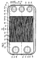
- eine schematische Draufsicht auf eine Kontaktplatte einer Brennstoffzelleneinheit;
- Fig. 6
- eine schematische Draufsicht auf einen Fluidführungsrahmen einer Brennstoffzelleneinheit;
- Fig. 7
- den rechten Teil eines schematischen Querschnitts durch vier in der Stapelrichtung des Brennstoffzellenblockverbunds aufeinanderfolgende Brennstoffzelleneinheiten;
- Fig. 8
- den rechten Teil eines schematischen Längsschnitts durch vier längs der Stapelrichtung des Brennstoffzellenblockverbunds aufeinanderfolgende Brennstoffzelleneinheiten im Bereich eines Gaskanals;
- Fig. 9
- den rechten Teil eines schematischen Längsschnitts durch vier längs der Stapelrichtung des Brennstoffzellenblockverbunds aufeinanderfolgende Brennstoffzelleneinheiten im Bereich zwischen zwei Gaskanälen;
- Fig. 10
- eine schematische perspektivische Darstellung eines einen Gaskanal umgebenden ringförmigen Abstützelements einer Brennstoffzelleneinheit;
- Fig. 11
- eine vergrößerte Darstellung des Bereichs I aus Fig. 7;
- Fig. 12
- eine schematische perspektivische Explosionsdarstellung zweier in der Stapelrichtung aufeinanderfolgender Brennstoffzelleneinheiten;
- Fig. 13
- eine Draufsicht auf das Gehäuse einer Brennstoffzelleneinheit im Bereich einer Gasdurchgangsöffnung bei einer zweiten Ausführungsform der Brennstoffzelleneinheit, welche eine Vielzahl einstückig mit den Gehäusewänden ausgebildeter Abstützelemente aufweist;
- Fig. 14
- einen schematischen Schnitt durch das Gehäuse der Brennstoffzelleneinheit aus Fig. 13 längs der Linie 14-14 in Fig. 13; und
- Fig. 15
- einen schematischen Schnitt durch das Gehäuse der Brennstoffzelleneinheit aus Fig. 13 längs der Linie 15-15 in Fig. 13.
- Fig. 1
- a schematic perspective view of a fuel cell device with supply lines and discharge lines for the oxidizing agent and the fuel gas;
- Fig. 2
- a schematic vertical section through a arranged in the housing of the fuel cell device of Figure 1 fuel cell block assembly.
- Fig. 3
- a top view of end plates of the fuel cell block assembly of Fig. 2;
- Fig. 4
- a schematic longitudinal section through a cathode-anode-electrolyte unit with adjoining contact plates;
- Figure 5
- a schematic plan view of a contact plate of a fuel cell unit;
- Fig. 6
- a schematic plan view of a fluid guide frame of a fuel cell unit;
- Fig. 7
- the right part of a schematic cross section through four in the stacking direction of the fuel cell block assembly sequential fuel cell units;
- Fig. 8
- the right part of a schematic longitudinal section through four along the stacking direction of the fuel cell block assembly sequential fuel cell units in the region of a gas channel;
- Fig. 9
- the right part of a schematic longitudinal section through four along the stacking direction of the fuel cell block assembly successive fuel cell units in the region between two gas ducts;
- Fig. 10
- a schematic perspective view of a surrounding a gas channel annular support member of a fuel cell unit;
- Fig. 11
- an enlarged view of the area I of Fig. 7;
- Fig. 12
- a schematic perspective exploded view of two successive in the stacking direction fuel cell units;
- Fig. 13
- a plan view of the housing of a fuel cell unit in the region of a gas passage opening in a second embodiment of the fuel cell unit, which has a plurality of integrally formed with the housing walls supporting elements;
- Fig. 14
- a schematic section through the housing of the fuel cell unit of Figure 13 along the line 14-14 in Fig. 13 .; and
- Fig. 15
- a schematic section through the housing of the fuel cell unit of FIG. 13 along the line 15-15 in Fig. 13th
Gleiche oder funktional äquivalente Elemente sind in allen Figuren mit denselben Bezugszeichen bezeichnet.Equal or functionally equivalent elements are the same in all figures Reference numeral.
Eine in den Fig. 1 bis 12 dargestellte, als Ganzes mit 100 bezeichnete Brennstoffzellenvorrichtung
umfaßt ein im wesentlichen quaderförmiges Gehäuse
102 (siehe Fig. 1), in das eine Oxidationsmittel-Zuführleitung 104 mündet,
über die dem Innenraum des Gehäuses 102 ein Oxidationsmittel, beispielsweise
Luft oder reiner Sauerstoff, von einem (nicht dargestellten) Zuführgebläse
unter einem Überdruck von beispielsweise ungefähr 50 mbar zugeführt
wird.A fuel cell device, shown as a whole as 100 in FIGS. 1 to 12
comprises a substantially cuboid housing
102 (see FIG. 1), into which an
Ferner mündet in das Gehäuse 102 eine Oxidationsmittel-Abführleitung 105,
durch welche überschüssiges Oxidationsmittel aus dem Innenraum des Gehäuses
102 abführbar ist.Further, in the
Im Innenraum des Gehäuses 102 ist ein in den Fig. 2 und 3 als Ganzes dargestellter
Brennstoffzellenblockverbund 106 angeordnet, welcher eine untere
Endplatte 108, eine mittlere obere Endplatte 110, zwei seitliche obere Endplatten
111 und eine Vielzahl zwischen der unteren Endplatte 108 und den
oberen Endplatten 110, 111 angeordneter, längs einer Stapelrichtung 112
aufeinanderfolgender Brennstoffzelleneinheiten 114 umfaßt. In the interior of the
Wie am besten aus Fig. 12 zu ersehen ist, welche eine perspektivische Explosionsdarstellung
zweier längs der Stapelrichtung 112 aufeinanderfolgender
Brennstoffzelleneinheiten 114 zeigt, umfaßt jede der Brennstoffzelleneinheiten
114 eine im wesentlichen plattenförmige Kathoden-Anoden-Elektrolyt-Einheit
116 (im folgenden kurz als KAE-Einheit bezeichnet), die zwischen einer Kontaktplatte
118 und einem Fluidführungsrahmen 120 gehalten ist.As best seen in Fig. 12, which is an exploded perspective view
two successive along the stacking
Die KAE-Einheit 116 umfaßt, wie in Fig. 4 rein schematisch dargestellt ist, ein
gasdurchlässiges, elektrisch leitfähiges Substrat 121, das beispielsweise als
Metalldrahtgeflecht, Metalldrahtvlies, Metalldrahtgewebe, Metalldrahtgestrick
oder als ein aus gesinterten oder gepreßten Metallpartikeln bestehender poröser
Körper ausgebildet sein kann, wobei durch das Substrat 121 ein Brenngas
aus einem an das Substrat 121 angrenzenden Brenngasraum 124 hindurchtreten
kann.The
Ferner umfaßt die KAE-Einheit 116 eine auf dem Substrat 121 angeordnete
plattenförmige Anode 122 aus einem elektrisch leitfähigen keramischen Material,
beispielsweise Ni-ZrO2-Cermet (Keramik-Metall-Gemisch), welches porös
ist, um dem Brenngas aus dem Brenngasraum 124 den Durchtritt durch die
Anode 122 zu dem an die Anode 122 angrenzenden Elektrolyten 126 zu ermöglichen.Further, the
Als Brenngas kann beispielsweise ein kohlenwasserstoffhaltiges Gasgemisch oder reiner Wasserstoff verwendet werden.As a fuel gas, for example, a hydrocarbon-containing gas mixture or pure hydrogen can be used.
Der Elektrolyt 126 ist vorzugsweise als Feststoffelektrolyt ausgebildet uns beispielsweise
aus Yttrium-stabilisiertem Zirkoniumdioxid gebildet. The
Auf der der Anode 122 gegenüberliegenden Seite des Elektrolyten 126 grenzt
an denselben eine plattenförmige Kathode 128, die aus einem elektrisch leitfähigen
keramischen Material, beispielsweise aus LaMnO3, gebildet ist und eine
Porosität aufweist, um einem Oxidationsmittel, beispielsweise Luft oder reinem
Sauerstoff, aus einem an die Kathode 128 angrenzenden Oxidationsmittelraum
130 den Durchtritt zu dem Elektrolyten 126 zu ermöglichen.On the opposite side of the
Der Elektrolyt 126 ist im wesentlichen gasdicht, so daß kein Oxidationsmittel
aus dem Oxidationsmittelraum 130 durch den Elektrolyten 126 in den Brenngasraum
124 und kein Brenngas aus dem Brenngasraum 124 durch den
Elektrolyten 126 in den Oxidationsmittelraum 130 gelangen kann.The
Im Betrieb der Brennstoffzellenvorrichtung weist die KAE-Einheit 116 jeder
Brennstoffzelleneinheit 114 eine Temperatur von beispielsweise ungefähr
850°C auf, bei welcher der Elektrolyt 126 für Sauerstoffionen leitfähig ist. Das
Oxidationsmittel aus dem Oxidationsmittelraum 130 nimmt an der Anode 122
Elektronen auf und gibt zweiwertige Sauerstoffionen an den Elektrolyten 126
ab, welche durch den Elektrolyten 126 hindurch zur Anode 122 wandern. An
der Anode 122 wird das Brenngas aus dem Brenngasraum 124 durch die
Sauerstoffionen aus dem Elektrolyten 126 oxidiert und gibt dabei Elektronen
an die Anode 122 ab.In operation of the fuel cell device, the
Die Kontaktplatten 118 dienen dazu, die bei der Reaktion an der Anode 122
frei werdenden Elektronen von der Anode 122 über das Substrat 121 abzuführen
bzw. die für die Reaktion an der Kathode 128 benötigten Elektronen der
Kathode 128 zuzuführen. The
Hierzu besteht jede der Kontaktplatten 118 aus einem elektrisch gut leitfähigen
Metallblech, das (wie am besten aus Fig. 5 zu ersehen ist) mit einer Vielzahl
von Kontaktelementen 132 versehen ist, welche beispielsweise die Form
sich in der Längsrichtung 133 der Kontaktplatte 118 erstreckender Rippen
aufweisen, die in der Querrichtung 131 der Kontaktplatte 118 aufeinander folgen,
wobei die in der Querrichtung 131 aufeinanderfolgenden Kontaktelemente
132 unmittelbar aneinander angrenzen und von der Mittelebene 139 der Kontaktplatte
118 aus abwechselnd zu verschiedenen Seiten der Kontaktplatte
118 vorspringen. Die von der Kontaktplatte 118 nach oben und somit zu der
Anode 122 der derselben Brennstoffzelleneinheit 114 zugehörigen KAE-Einheit
116 vorspringenden anodenseitigen Kontaktelemente sind mit dem Bezugszeichen
132a, die von der Kontaktplatte 118 nach unten und damit zu der Kathode
128 der einer benachbarten Brennstoffzelleneinheit 114 zugehörigen
KAE-Einheit 116 vorspringenden kathodenseitigen Kontaktelemente sind mit
dem Bezugszeichen 132b bezeichnet.For this purpose, each of the
Jedes der Kontaktelemente 132 weist einen mittigen, streifenförmigen Kontaktbereich
137 auf, an dem es mit einer angrenzenden KAE-Einheit 116 in
elektrisch leitendem Kontakt steht (siehe insbesondere Fig. 4 und Fig. 7).Each of the
Die Kontaktbereiche 137 der anodenseitigen Kontaktelemente 132a einer
Kontaktplatte 118 stehen mit dem Substrat 121 und somit mit der Anode 122
der derselben Brennstoffzelleneinheit 114 zugehörigen KAE-Einheit 116 in
elektrischem Flächenkontakt, so daß Elektronen von der jeweiligen Anode 122
in die Kontaktplatte 118 gelangen können.The
Die kathodenseitigen Kontaktelemente 132b der Kontaktplatten 118 stehen
jeweils mit der Kathode 128 der einer benachbarten Brennstoffzelleneinheit
114 zugehörigen KAE-Einheit 116 in elektrisch leitfähigem Flächenkontakt, so
daß Elektronen von der Kontaktplatte 118 zu der Kathode 128 gelangen können.
Auf diese Weise ermöglichen die Kontaktplatten 118 den Ladungsausgleich
zwischen den Anoden 122 und den Kathoden 128 längs der Stapelrichtung
112 aufeinanderfolgender KAE-Einheiten 116.The cathode-
Die an den Enden des Brennstoffzellenblockverbunds 106 angeordneten Kontaktplatten
118 sind (auf nicht zeichnerisch dargestellte Weise) mit einem externen
Stromkreislauf verbunden, um die an diesen randständigen Kontaktplatten
118 entstehenden elektrischen Ladungen abzugreifen.The arranged at the ends of the fuel
Das aus den Kontaktelementen 132 gebildete Kontaktfeld 134 jeder Kontaktplatte
118 weist die Struktur eines in der Querrichtung 131 der Kontaktplatte
118 gewellten Wellblechs auf.The formed from the
Wie am besten aus der Draufsicht der Fig. 5 zu ersehen ist, ist das mit den
Kontaktelementen 132 versehene mittige, im wesentlichen rechteckige Kontaktfeld
134 jeder Kontaktplatte 118 in einen ebenen, im wesentlichen rechteckigen
Gasführungsbereich 136 der Kontaktplatte 118 eingebettet.As best seen in the plan view of Fig. 5, that is with the
Der Gasführungsbereich 136 weist zu beiden Seiten des Kontaktfeldes 134 jeweils
einen Seitenbereich 140a bzw. 140b auf.The
In dem Seitenbereich 140a sind mehrere, beispielsweise zwei, im wesentlichen
kreisförmige Brenngasdurchgangsöffnungen 142 ausgebildet.In the side area 140a, a plurality, for example two, are substantially
circular fuel
Jede der Brenngasdurchgangsöffnungen 142 ist von einem ringförmigen Randbereich
144 umgeben, wobei jeder der Bereiche 142 gegenüber dem Gasführungsbereich
136 längs der Stapelrichtung 112 nach unten versetzt und mit
dem Gasführungsbereich 136 über eine Schräge 146, welche an einer inneren
Biegelinie 148 an den jeweiligen Randbereich 144 und längs einer äußeren
Biegelinie 150 an den Gasführungsbereich 136 angrenzt, verbunden ist.Each of the fuel
Die Brenngasdurchgangsöffnungen 142 dienen dem Durchtritt von den Brennstoffzelleneinheiten
114 zuzuführendem Brenngas durch die jeweilige Kontaktplatte
118.The fuel
Der dem Seitenbereich 140a gegenüberliegende Seitenbereich 140b jeder
Kontaktplatte 118 ist mit mehreren, beispielsweise mit drei, im wesentlichen
kreisförmigen Abgasdurchgangsöffnungen 152 versehen.The
Jede der Abgasdurchgangsöffnungen 152 ist von einem ringförmigen Randbereich
154 umgeben, welcher gegenüber dem Gasführungsbereich 136 der
Kontaktplatte 118 längs der Stapelrichtung 112 nach unten versetzt ist und
mit dem Gasführungsbereich 136 über eine Schräge 156, welche an einer inneren
Biegelinie 158 an den Randbereich 154 und längs einer äußeren Biegelinie
160 an den Gasführungsbereich 136 angrenzt, mit dem Gasführungsbereich
136 verbunden ist (siehe insbesondere Fig. 8).Each of the exhaust
Die Abgasdurchgangsöffnungen 152 der Kontaktplatte 118 ermöglichen den
Durchtritt von aus den Brennstoffzelleneinheiten 114 abzuführendem Abgas,
welches überschüssiges Brenngas und Verbrennungsprodukte, insbesondere
Wasser, enthält, durch die Kontaktplatte 118.The exhaust
Ferner ist jede Kontaktplatte 118 mit einem den Gasführungsbereich 136 umschließenden
Randbereich 162 versehen, welcher senkrecht zur Stapelrichtung
112 ausgerichtet ist, gegenüber dem Gasführungsbereich 136 längs der Stapelrichtung
112 nach oben versetzt ist und mit dem Gasführungsbereich 136
über eine Schräge 164, welche längs einer inneren Biegelinie 166 an den Gasführungsbereich
136 und längs einer äußeren Biegelinie 168 an den Randbereich
162 angrenzt, verbunden ist.Furthermore, each
Der äußere Rand des Randbereichs 162 ist mit einem Verbindungsflansch 170
versehen, welcher längs einer Biegelinie 172 an den Randbereich 162 angrenzt
und sich von dem Randbereich 162 im wesentlichen parallel zu der Stapelrichtung
112 nach unten erstreckt.The outer edge of the
Die im wesentlichen parallel zur Stapelrichtung 112 ausgerichtete Außenfläche
des Verbindungsflansches 170 bildet eine erste Verbindungsfläche 174.The substantially parallel to the stacking
Jede der Kontaktplatten 118 ist als Blechformteil ausgebildet, welches aus
einer im wesentlichen ebenen, im wesentlichen rechteckigen Blechlage durch
Prägen und/oder Tiefziehen sowie durch Ausstanzen oder Ausschneiden der
Brenngasdurchgangsöffnungen 142 und der Abgasdurchgangsöffnungen 152
gebildet ist.Each of the
Auch die Fluidführungsrahmen 120 sind als Blechformteile aus einer im wesentlichen
ebenen, im wesentlichen rechteckigen Blechlage gebildet.The
Wie am besten aus Fig. 6 zu ersehen ist, weist jeder Fluidführungsrahmen 120
eine im wesentlichen rechteckige, mittige Durchtrittsöffnung 176 für den
Durchtritt der KAE-Einheit 116 derselben Brennstoffzelleneinheit 114 auf.As best seen in FIG. 6, each fluid guide frame 120
a substantially rectangular, central passage opening 176 for the
Passage of the
Diese Durchtrittsöffnung 176 ist von einem im wesentlichen ebenen, senkrecht
zur Stapelrichtung 112 ausgerichteten Gasführungsbereich 178 umgeben, welcher
zwei Seitenbereiche 180a, 180b umfaßt, welche einander an der Durchtrittsöffnung
176 gegenüberliegen. This passage opening 176 is of a substantially planar, vertical
Surrounding the stacking
In dem Seitenbereich 180a sind mehrere, beispielsweise zwei, im wesentlichen
kreisförmige Brenngasdurchgangsöffnungen 182 ausgebildet, welche den
Durchtritt von Brenngas durch den Fluidführungsrahmen 120 ermöglichen.In the side area 180a, a plurality, for example two, are substantially
circular fuel
In dem dem Seitenbereich 180a gegenüberliegenden Seitenbereich 180b des
Gasführungsbereichs 178 sind mehrere, beispielsweise drei, im wesentlichen
kreisförmige Abgasdurchgangsöffnungen 184 ausgebildet, welche den Durchtritt
von aus den Brennstoffzelleneinheiten 114 abzuführendem Abgas durch
den Fluidführungsrahmen 120 ermöglichen.In the
Der Gasführungsbereich 178 jedes Fluidführungsrahmens 120 ist an seinem
äußeren Rand mit einem Verbindungsflansch 186 versehen, welcher längs
einer Biegelinie 188 an den Gasführungsbereich 178 angrenzt und sich von
dem Gasführungsbereich 178 im wesentlichen parallel zu der Stapelrichtung
112 nach unten erstreckt.The
Die im wesentlichen parallel zur Stapelrichtung 112 ausgerichtete Innenseite
des Verbindungsflansches 186 bildet eine zweite Verbindungsfläche 190.The substantially parallel to the stacking
Jeweils ein Fluidführungsrahmen 120 und eine Kontaktplatte 118 bilden zusammen
ein Gehäuse 192 einer Brennstoffzelleneinheit 114.In each case, a
Wie aus den Fig. 7 bis 9 zu ersehen ist, sind der Fluidführungsrahmen 120 und
die Kontaktplatte 118 eines solchen Gehäuses 192 einer Brennstoffzelleneinheit
114 an ihren Verbindungsflanschen 186 bzw. 170 aneinander festgelegt
und gasdicht gegeneinander abgedichtet. As can be seen from Figs. 7 to 9, the
Dabei umgreift der im wesentlichen parallel zur Stapelrichtung 112 ausgerichtete
Verbindungsflansch 186 des Fluidführungsrahmens 120 den ebenfalls im
wesentlichen parallel zur Stapelrichtung 112 ausgerichteten Verbindungsflansch
170 der Kontaktplatte 118 derart, daß die erste Verbindungsfläche an
dem Verbindungsflansch 170 der Kontaktplatte 118 und die zweite Verbindungsfläche
190 an dem Verbindungsflansch 186 des Fluidführungsrahmens
120 einander gegenüberstehen.In this case, the substantially aligned parallel to the stacking
Wie aus den Fig. 7 bis 9 zu ersehen ist, sind der untere Rand 194 und die
zweite Verbindungsfläche 190 des Verbindungsflansches 186 des Fluidführungsrahmens
120 mittels einer Schweißnaht 196 mit der ersten Verbindungsfläche
174 und an dem unteren Rand 198 des Verbindungsflansches 170 der
Kontaktplatte 118 verbunden und so an dem Verbindungsflansch 170 der Kontaktplatte
118 festgelegt.As can be seen from Figs. 7 to 9, the
Dabei sorgt die längs der Ränder der Kontaktplatte 118 und des Fluidführungsrahmens
120 umlaufende Schweißnaht 196 für einen gasdichten Verschluß
des Zwischenraums zwischen den Verbindungsflanschen 186 und 170.In doing so, it ensures along the edges of the
Die Schweißnaht 196 kann beispielsweise im Laserschweißverfahren oder im
Elektronenstrahlverfahren hergestellt werden.The
Alternativ oder ergänzend zu einer Verschweißung kann die Verbindung zwischen
den Verbindungsflanschen 186 und 170 auch durch Verlötung, insbesondere
durch eine Hartlötung, erfolgen.Alternatively or in addition to a weld, the connection between
the connecting
Dadurch, daß die Verbindungsflansche 186 und 170 und insbesondere die
einander gegenüberstehenden Verbindungsflächen 174 und 190 parallel zur
Stapelrichtung 112 ausgerichtet sind, ist die Kontaktplatte 118 in einer Art
Schiebesitz in dem Fluidführungsrahmen 120 aufgenommen, so daß die Verbindungsflansche
186 und 170 auch dann problemlos gasdicht miteinander
verbunden werden können, wenn der Abstand zwischen den unteren Rändern
194 und 198 längs der Stapelrichtung 112 aufgrund von Fertigungstoleranzen
bei der Herstellung der Kontaktplatte 118 und des Fluidführungsrahmens 120
oder aufgrund von Montagetoleranzen beim Zusammenbau der Brennstoffzelleneinheit
114 längs des Randes der Kontaktplatte 118 und des Randes des
Fluidführungsrahmens 120 variiert.Characterized in that the connecting
Wie am besten aus Fig. 8 zu ersehen ist, sind im Bereich der Abgasdurchgangsöffnungen
152, 184 ringförmige Abstützelemente 200 angeordnet, welche
mit ihrer Unterseite 202 jeweils an der Oberseite eines eine Abgasdurchgangsöffnung
152 umgebenden Randbereichs 154 einer Kontaktplatte 118 und
mit ihrer Oberseite 204 jeweils an der Unterseite des eine Abgasdurchgangsöffnung
184 in dem Fluidführungsrahmen 120 umgebenden Bereichs des
Fluidführungsrahmens 120 anliegen.As best seen in Fig. 8, are in the region of the
Ähnliche, sich nur in ihren Abmessungen von den Abstützelementen 200 an
den Abgasdurchgangsöffnungen 152, 184 unterscheidende Abstützelemente
200 sind zwischen der Kontaktplatte 118 und dem Fluidführungsrahmen 120
im Bereich der Brenngasdurchgangsöffnungen 142, 182 angeordnet.Similar, only in their dimensions of the
Ein solches Abstützelement 200 ist in Fig. 10 perspektivisch dargestellt und
weist die Form eines Kreisringes mit einem im wesentlichen rechteckigen
Querschnitt auf. Um einen Gasdurchtritt von der Innenseite zur Außenseite des
Abstützelements 200 (oder in umgekehrter Richtung) zu ermöglichen, ist das
Abstützelement 200 mit radial ausgerichteten, das Abstützelement 200 von
dessen Innenseite 206 bis zu dessen Außenseite 208 durchsetzenden, in der
Umfangsrichtung des Abstützelements 200 voneinander beabstandeten, im
wesentlichen zylindrischen Gasdurchtrittskanälen 210 versehen.Such a
Die Abstützelemente 200 dienen dazu, die Kontaktplatte 118 und den Fluidführungsrahmen
120 eines Gehäuses 192 einer Brennstoffzelleneinheit 114 auf
Abstand voneinander zu halten und so ein Zusammendrücken des Gehäuses
192 durch die bei der Montage des Brennstoffzellenblockverbunds 106 auf das
Gehäuse 192 einwirkende Einspannkraft zu verhindern.The
Die Abstützwirkung der Abstützelemente 200 spielt bei der Betriebstemperatur
der Brennstoffzellenvorrichtung 100, welche bei einer Hochtemperatur-Brennstoffzellenvorrichtung
im Bereich von ungefähr 800°C bis ungefähr 1000°C
liegt, eine besondere Rolle, da bei solchen Betriebstemperaturen die Streckgrenze
des Stahls, aus welchem die Kontaktplatte 118 und der Fluidführungsrahmen
120 gebildet sind, auf Werte von weniger als ungefähr 10 N/mm2 abfällt,
so daß ohne das Vorhandensein der Abstützelemente 200 bereits geringe
Einspannkräfte dazu ausreichen würden, die Kontaktplatte 118 und den Fluidführungsrahmen
120 eines Gehäuses 192 gegeneinander zu drücken.The supporting action of the
Die Abstützelemente 200 können aus einem metallischen Material oder aus
einem keramischen Material gebildet sein.The
Statt eines massiven Abstützelements mit Gasdurchtrittskanälen 210 kann
auch ein Abstützelement verwendet werden, welches als poröses Sinterelement
aus einem keramischen und/oder einem metallischen Material gebildet
ist. Ein solches Sinterelement weist bereits aufgrund seiner Porosität eine
ausreichende Gasdurchlässigkeit auf, so daß ein solches Element nicht mit
Gasdurchtrittskanälen versehen werden muß. Instead of a solid support member with
Wie am besten aus den Fig. 8 und 12 zu ersehen ist, ist zwischen der Unterseite
des Randbereichs 154 jeder Abgasdurchgangsöffnung 152 in einer Kontaktplatte
118 und der Oberseite des Gasführungsbereichs 178 des in der Stapelrichtung
112 unter der betreffenden Kontaktplatte 118 angeordneten Fluidführungsrahmens
120 einer benachbarten Brennstoffzelleneinheit 114 jeweils
eine Gaskanal-Dichtung 212 angeordnet. Jede der Gaskanaldichtungen 212
dichtet den Zwischenraum zwischen der angrenzenden Kontaktplatte 118 und
dem angrenzenden Fluidführungsrahmen 120 gasdicht ab und umschließt die
jeweilige Abgasdurchgangsöffnung 152, 184 in der Kontaktplatte 118 bzw. in
dem Fluidführungsrahmen 120 ringförmig.As best seen in Figures 8 and 12, is between the bottom
the
Wie am besten aus Fig. 8 zu erkennen ist, begrenzen die in der Stapelrichtung
112 aufeinanderfolgenden Kontaktplatten 118 und Fluidführungsrahmen 120
mit den jeweils dazwischen angeordneten Abstützelementen 200 und Gaskanal-Dichtungen
212 mehrere, beispielsweise drei, Abgaskanäle 214, in welche
Abgas aus den Brenngasräumen 124 der Brennstoffzelleneinheiten 114 durch
die Gasdurchtrittskanäle 210 in den Abstützelementen 200 eintreten kann und
die durch die Gaskanal-Dichtungen 212 gasdicht von den Oxidationsmittelräumen
130 der Brennstoffzelleneinheiten 114 getrennt sind.As best seen in Figure 8, they limit in the stacking
In entsprechender Weise sind auch zwischen den Randbereichen 144 der
Brenngasdurchgangsöffnungen 142 jeder Kontaktplatte 118 und dem Fluidführungsrahmen
120 einer in der Stapelrichtung 112 unter der betreffenden
Kontaktplatte 118 angeordneten Brennstoffzelleneinheit 114 Gaskanal-Dichtungen
212 angeordnet, welche die Brenngasdurchgangsöffnungen 142 und
182 in der Kontaktplatte 118 bzw. in dem Fluidführungsrahmen 120 ringförmig
umschließen, so daß die in der Stapelrichtung 112 aufeinanderfolgenden Kontaktplatten
118 und Fluidführungsrahmen 120 zusammen mit den jeweils
dazwischen angeordneten Abstützelementen 200 und Gaskanal-Dichtungen
212 mehrere, beispielsweise zwei, Brenngaskanäle 216 bilden, welche sich
längs der Stapelrichtung 112 erstrecken, aus welchen Brenngas durch die Gasdurchtrittskanäle
210 in den Abstützelementen 200 in die Brenngasräume 124
der Brennstoffzelleneinheiten 114 austreten kann und welche durch die Gaskanal-Dichtungen
212 gasdicht von den Oxidationsmittelräumen 130 der
Brennstoffzelleneinheiten 114 getrennt sind.Similarly, between the
Die Gaskanal-Dichtungen 112 können beispielsweise jeweils eine Flachdichtung aus Glimmer, insbesondere aus Phlogopit, umfassen.For example, the gas channel seals 112 may each be a flat gasket of mica, in particular of phlogopite.
Alternativ oder ergänzend hierzu kann auch vorgesehen sein, daß die Gaskanal-Dichtungen
212 jeweils eine gasdichte, elektrisch isolierende Beschichtung
umfassen, die als Paste im Siebdruckverfahren oder mittels Walzenbeschichtung
auf die Oberfläche der Kontaktplatte 118 oder auf die Oberfläche des
Fluidführungsrahmens 120 aufgebracht wird.Alternatively or additionally, it can also be provided that the gas channel seals
212 each a gas-tight, electrically insulating coating
comprising, as a paste by screen printing or by roll coating
on the surface of the
Ferner ist der Brenngasraum 124 jeder Brennstoffzelleneinheit 114 von dem
Oxidationsmittelraum 130 einer in der Stapelrichtung 112 darüber angeordneten
Brennstoffzelleneinheit 114 gasdicht durch eine Brenngasraum-Dichtung
218 getrennt, deren Aufbau im folgenden unter Bezugnahme auf die Figur 11
detailliert beschrieben wird.Further, the
Wie aus Fig. 11 zu ersehen ist, weist das Substrat 121 der KAE-Einheit 116
einen verdichteten Außenbereich 220 auf, der sich längs des gesamten Umfangs
des Substrats 121 erstreckt und in welchem die Dicke des Substrats 121
durch einen Pressvorgang auf beispielsweise ungefähr 20 % der Anfangsdicke,
d.h. der Dicke des ungepreßten Bereichs des Substrats 121, reduziert worden
ist. As can be seen from FIG. 11, the
Bei diesem Verdichtungsvorgang wird die Porosität des Substrats 121, d.h. der
prozentuale Anteil des gasgefüllten Volumens des Substrats 121 am Gesamtvolumen
des Substrats 121, in dem verdichteten Außenbereich 220 auf nahezu
Null verringert.In this densification process, the porosity of the
Um dies zu erreichen, wird bei einem Substrat 121, das eine Porosität von x %
aufweist, die Dicke im verdichteten Außenbereich 220 durch den Verdichtungsvorgang
vorzugsweise auf (100 - x)% der Anfangsdicke reduziert; im
Falle einer Porosität von 80 % also auf 20 % der Anfangsdicke.In order to achieve this, for a
Das Substrat 121 wird mit der Unterseite 222 des verdichteten Außenbereichs
220 auf den Fluidführungsrahmen 120 aufgelegt und durch einen Schweißvorgang,
beispielsweise durch Laserschweißen, Elektronenstrahlschweißen,
Buckelschweißen oder Kondensatorentladungsschweißen, gasdicht mit dem
metallischen Material des Fluidführungsrahmens 120 verbunden.The
Durch den Schweißvorgang wird in dem verdichteten Außenbereich 220 des
Substrats 121 eine keine Porosität mehr aufweisende gasdichte Zone 224 gebildet,
welche sich von der Unterseite 222 bis zu der Oberseite 226 des verdichteten
Außenbereichs 220 durch den verdichteten Außenbereich 220 des
Substrats 121 hindurch erstreckt und eine sich längs des gesamten Umfangs
des Substrats 121 erstreckende gasdichte Barriere bildet, welche einen Gasdurchtritt
von dem außerhalb der gasdichten Zone 224 liegenden Randbereich
228 in den von der gasdichten Zone 224 umschlossenen Innenbereich 230 des
Substrats 121 ebenso wie einen Gasdurchtritt in umgekehrter Richtung verhindert. By the welding process is in the compacted
Statt durch Verschweißen des Substrats 121 mit dem Fluidführungsrahmen
120 kann die gasdichte Zone 224 im verdichteten Außenbereich 220 des
Substrats 221 auch durch Verlöten des Substrats 121 mit dem Fluidführungsrahmen
120 gebildet werden. Dabei wird das verwendete Lot aufgrund der Kapillarwirkung
in die noch vorhandenen Poren und Durchgangskanäle in dem
verdichteten Außenbereich 220 des Substrats 121 hineingesogen und verschließt
diese Durchgangsöffnungen dauerhaft, so daß eine sich über die gesamte
Höhe des verdichteten Außenbereichs 220 erstreckende gasdichte Zone
224 entsteht.Instead, by welding the
Wie aus Fig. 11 ferner zu ersehen ist, erstreckt sich der gasdichte Elektrolyt
126 der KAE-Einheit 116 über den Rand der gasdurchlässigen Anode 122 und
über den Rand der gasdurchlässigen Kathode 128 hinaus und liegt mit seiner
Unterseite direkt auf der Oberseite 226 des verdichteten Außenbereichs 220
des Substrats 121 auf.As can also be seen from Fig. 11, the gas-tight electrolyte extends
126 of the
Dieser direkt auf dem Substrat 121 angeordnete Außenbereich 232 des Elektrolyts
126 erstreckt sich zum Rand des Substrats 121 hin so weit nach außen,
daß er die gasdichte Zone 224 überdeckt und somit der Innenbereich 230 des
Substrats 121 gasdicht von dem über dem Elektrolyten 126 liegenden Oxidationsmittelraum
130 getrennt ist, ohne daß für diese gasdichte Abtrennung ein
zusätzliches Abdichtmedium benötigt wird.This arranged directly on the
Der Außenbereich 232 des Elektrolyten 126 bildet somit zusammen mit der
gasdichten Zone 224 des verdichteten Außenbereichs 220 des Substrats 121
eine gasdichte Brenngasraum-Dichtung 218, welche den oberhalb des Fluidführungsrahmens
120 angeordneten Oxidationsmittelraum 130 gasdicht von
dem unterhalb des Fluidführungsrahmens 120 angeordneten Brenngasraum
124 trennt.The
Bei der in Fig. 11 dargestellten Ausführungsform der Brenngasraum-Dichtung
218 wird diese Dichtung im Bereich zwischen dem äußeren Rand der Anode
122 und der gasdichten Zone 224 des verdichteten Außenbereichs 220 des
Substrats 121 durch den über die Anode 122 hinausgeführten Außenbereich
232 des Elektrolyten 126 gebildet.In the embodiment of the fuel gas space seal illustrated in FIG. 11
218, this seal is in the area between the outer edge of the
Alternativ oder ergänzend hierzu kann auch vorgesehen sein, daß die Brenngasraum-Dichtung
218 einen aus einer Vergußmasse gebildeten Dichtungsbereich
umfaßt, welcher den Bereich vom äußeren Rand der Anode 122 bis zu
der gasdichten Zone 224 gasdicht überdeckt.Alternatively or additionally, it may also be provided that the fuel gas space seal
218 a sealing region formed from a potting compound
comprising the area from the outer edge of the
Eine solche Vergußmasse kann beispielsweise ein Glaslot, ein Metallot oder eine anorganische Paste umfassen.Such a potting compound, for example, a glass solder, a Metallot or an inorganic paste.
Umfaßt die Brenngasraum-Dichtung 218 sowohl einen bis über die gasdichte
Zone 224 hinausgezogenen Elektrolyten 126 als auch eine diesen Außenbereich
232 des Elektrolyten 126 überdeckende Vergußmasse, so wird hierdurch
eine besonders dichte und zuverlässige Abdichtung des Brenngasraums 124
gegenüber dem Oxidationsmittelraum 130 erzielt.Includes the fuel
Wie insbesondere aus Fig. 7 zu ersehen ist, liegt im montierten Zustand einer
Brennstoffzelleneinheit 114 die KAE-Einheit 116 der betreffenden Brennstoffzelle
114 mit dem Substrat 121 auf den anodenseitigen Kontaktelementen
132a der Kontaktplatte 118 der Brennstoffzelleneinheit 114 auf. As can be seen in particular from Fig. 7, is in the assembled state of a
Ferner liegt die KAE-Einheit 116 mit dem verdichteten Außenbereich 220 des
Substrats 121 auf dem Fluidführungsrahmen 120 derselben Brennstoffzelleneinheit
114 auf, wobei sich der unverdichtete Bereich des Substrats 121 durch
die Durchtrittsöffnung 176 des Fluidführungsrahmen 120 hindurch erstreckt,
das Substrat 121 durch Verschweißung oder Verlötung an dem Fluidführungsrahmen
120 festgelegt ist und der Fluidführungsrahmen 120 durch Verschweißung
an der Schweißnaht 196 oder durch Verlötung seines Verbindungsflansches
186 mit dem Verbindungsflansch 170 der Kontaktplatte 118 an
der Kontaktplatte 118 festgelegt ist.Further, the
Die Brennstoffzelleneinheiten 114 des Brennstoffzellenblockverbunds 106 sind
längs der Stapelrichtung 112 so aufeinandergestapelt, daß die kathodenseitigen
Kontaktelemente 132b jeder Kontaktplatte 118 sich zu der Kathode der
KAE-Einheit 116 der darunter angeordneten Brennstoffzelleneinheit 114 erstrecken
und im elektrisch leitenden Kontakt an derselben anliegen.The
Dabei fluchten die Brenngasdurchgangsöffnungen 142, 182 und die Abgasdurchgangsöffnungen
152, 184 längs der Stapelrichtung 112 aufeinanderfolgender
Brennstoffzelleneinheiten 114 miteinander, um so die Brenngaskanäle
216 bzw. die Abgaskanäle 214 zu bilden.In this case, the fuel
Wie aus Fig. 2 zu ersehen ist, mündet an dem unterem Ende jedes Brenngaskanals
216 in denselben eine Brenngaszuführöffnung 234, welche die untere
Endplatte 108 des Brennstoffzellenblockverbunds 106 koaxial zu dem jeweiligen
Brenngaskanal 216 durchsetzt.As can be seen from Fig. 2, opens at the lower end of each
An das dem jeweiligen Brenngaskanal 216 abgewandte Ende der Brenngaszuführöffnung
234 ist eine Brenngas-Zweigleitung 236 angeschlossen, welche
von einer Brenngas-Zuführleitung 238 abzweigt, die durch das Gehäuse der
Brennstoffzellenvorrichtung 100 gasdicht hindurchgeführt und an eine (nicht
dargestellte) Brenngaszufuhr angeschlossen ist, welche der Brenngas-Zuführleitung
238 ein Brenngas, beispielsweise ein kohlenwasserstoffhaltiges Gas
oder reinen Wasserstoff, unter einem Überdruck von beispielsweise ungefähr
50 mbar zuführt.At the end of the fuel gas supply opening facing away from the respective
Die Abgaskanäle 214 des Brennstoffzellenblockverbunds 106 münden an ihren
oberen Enden jeweils in eine zum betreffenden Abgaskanal 214 koaxiale Abgasabführöffnung
240 (siehe Fig. 3), welche die seitliche obere Endplatte 111
durchsetzt und an ihrem dem jeweiligen Abgaskanal 214 abgewandten Ende
an jeweils eine Abgas-Zweigleitung 242 angeschlossen ist.The
Diese Abgas-Zweigleitungen 242 münden in eine gemeinsame Abgas-Abführleitung
244 (siehe Fig. 1), welche gasdicht durch das Gehäuse 102 der Brennstoffzellenvorrichtung
100 hindurchgeführt und an eine (nicht dargestellt) Abgasbehandlungseinheit
angeschlossen ist.These
Im Betrieb der Brennstoffzellenvorrichtung 100 strömt das Brenngas durch die
Brenngas-Zuführleitung 238, die Brenngas-Zweigleitungen 236 und die Brenngaszuführöffnungen
234 in die beiden Brenngaskanäle 216 ein und verteilt sich
von dort durch die Gasdurchtrittskanäle 210 der brenngaskanalseitigen Abstützelemente
200 auf die Brenngasräume 124 der Brennstoffzelleneinheiten
114, welche jeweils durch die Kontaktplatte 118, den Fluidführungsrahmen
120 und die KAE-Einheit 116 der betreffenden Brennstoffzelleneinheit 114 umschlossen
sind.In operation of the
Wie bereits beschrieben, wird das Brenngas zumindest teilweise an der den
jeweiligen Brenngasraum 124 begrenzenden Anode 122 der jeweiligen KAE-Einheit
116 oxidiert. As already described, the fuel gas is at least partially at the
respective
Das Oxidationsprodukt (Wasser) gelangt zusammen mit überschüssigem
Brenngas aus den Brenngasräumen 124 der Brennstoffzelleneinheiten 114
durch die Gasdurchtrittskanäle 210 der abgaskanalseitigen Abstützelemente
200 in die drei Abgaskanäle 214, aus welchen es durch die Abgasabführöffnungen
240, die Abgas-Zweigleitungen 242 und die Abgas-Abführleitung 244
zu der (nicht dargestellten) Abgasbehandlungseinheit abgeführt wird.The oxidation product (water) gets along with excess
Fuel gas from the
Dadurch, daß die Anzahl der Abgaskanäle 214 größer ist als die Anzahl der
Brenngaskanäle 216, wird eine besonders gleichmäßige Durchströmung der
Brenngasräume 124 zwischen den rippenförmigen Kontaktelementen 132 erzielt
und der Strömungswiderstand beim Durchströmen des Kontaktfeldes 134
reduziert.Characterized in that the number of
In der Abgasbehandlungseinheit wird beispielsweise das Reaktionsprodukt (Wasser) aus dem Abgasstrom entfernt, und überschüssiges Brenngas wird zu der Brenngaszufuhr geleitet, um nochmals der Brennstoffzellenvorrichtung 100 zugeführt zu werden.In the exhaust gas treatment unit, for example, the reaction product (Water) removed from the exhaust stream, and excess fuel gas is too the fuel gas fed to again the fuel cell device 100th to be fed.
Das für den Betrieb der Brennstoffzellenvorrichtung 100 benötigte Oxidationsmittel
(beispielsweise Luft oder reiner Sauerstoff) wird dem Innenraum des
Gehäuses 102 durch die Oxidationsmittel-Zuführleitung 104 zugeführt.The oxidant needed for operation of the fuel cell device 100
(For example, air or pure oxygen) is the interior of the
Im Innenraum des Gehäuses 102 verteilt sich das Oxidationsmittel auf die zwischen
den Brenngasräumen 124 der Brennstoffzelleneinheiten 114 ausgebildeten
Oxidationsmittelräume 130, welche durch jeweils eine Kontaktplatte 118
einer Brennstoffzelleneinheit 114 sowie durch den Fluidführungsrahmen 120
und die Kathode 128 der KAE-Einheit 116 einer benachbarten Brennstoffzelleneinheit
114 umschlossen sind.In the interior of the
In die Oxidationsmittelräume hinein und aus denselben wieder heraus gelangt
das Oxidationsmittel durch die Zwischenräume zwischen jeweils einem Fluidführungsrahmen
120 einer Brennstoffzelleneinheit 114 und der Kontaktplatte
118 der in der Stapelrichtung 112 darauffolgenden Brennstoffzelleneinheit 114,
soweit diese Zwischenräume nicht durch die Abstützelemente 200, welche die
Brenngaskanäle 216 bzw. die Abgaskanäle 214 umgeben, überdeckt sind.Into and out of the oxidant rooms
the oxidant through the spaces between each a
Wie bereits beschrieben, werden aus dem Oxidationsmittel an den Kathoden
128 der KAE-Einheiten 116 der Brennstoffzelleneinheiten 114 Sauerstoffionen
gebildet, welche durch die Elektrolyten 126 zu den Anoden 122 der KAE-Einheiten
116 der Brennstoffzelleneinheiten 114 wandern.As already described, from the oxidant at the
Überschüssiges Oxidationsmittel gelangt aus den Oxidationsmittelräumen 130
der Brennstoffzelleneinheiten 114 auf der der Eintrittsseite des Oxidationsmittels
gegenüberliegenden Seite hinaus und wird durch die Oxidationsmittel-Abführleitung
105 aus dem Innenraum des Gehäuses 102 der Brennstoffzellenvorrichtung
100 abgeführt.Excess oxidant passes out of the
Die Strömungsrichtung des Brenngases und des Abgases durch die Brennstoffzellenvorrichtung
100 ist in den Zeichnungen mit einfachen Pfeilen 246, die
Strömungsrichtung des Oxidationsmittels durch die Brennstoffzellenvorrichtung
100 mittels Doppelpfeilen 248 angegeben.The flow direction of the fuel gas and the exhaust gas through the
Die Strömungsrichtung des Oxidationsmittels durch die Oxidationsmittelräume
130 ist im wesentlichen parallel zu der Strömungsrichtung des Brenngases
durch die Brenngasräume 124. The flow direction of the oxidant through the
Um die längs der Stapelrichtung 112 aufeinanderfolgenden Brennstoffzelleneinheiten
114 durch äußere Verspannung aneinander festzulegen, sind mehrere
Verbindungsschrauben 250 (siehe Fig. 2 und 3) vorgesehen, welche
Durchgangsbohrungen 252 in der mittleren oberen Endplatte 110 des Brennstoffzellenblockverbunds
106 durchsetzen und an ihrem dem jeweiligen
Schraubenkopf 254 abgewandten Ende mit einem Außengewinde 256 versehen
sind, welches in jeweils eine Gewindebohrung 258 in der unteren Endplatte
108 des Brennstoffzellenverbunds 106 eingedreht ist, so daß die mittlere
obere Endplatte 110 und die untere Endplatte 108 durch die Verbindungsschrauben
250 gegeneinander verspannt werden und eine gewünschte Presskraft
über die Endplatten 108, 110 auf den mittigen, die Kontaktfelder 134
umfassenden Bereich des Stapels der Brennstoffzelleneinheiten 114 übertragbar
ist (siehe Fig. 2).To the fuel cell units successive along the stacking
Ferner sind mehrere Verbindungsschrauben 260 vorgesehen, welche Durchgangsbohrungen
262 in den seitlichen oberen Endplatten 111 des Brennstoffzellenblockverbunds
106 durchsetzen und an ihrem dem jeweiligen Schraubenkopf
264 abgewandten Ende mit einem Außengewinde 266 versehen sind,
welches in jeweils eine Gewindebohrung 268 in der unteren Endplatte 108 eingedreht
ist, so daß die seitlichen oberen Endplatten 111 und die untere Endplatte
108 durch die Verbindungsschrauben 260 gegeneinander verspannt sind
und eine gewünschte Presskraft über die Endplatten 108, 111 im Bereich der
Brenngaskanäle 216 bzw. der Abgaskanäle 214 auf den Stapel der Brennstoffzelleneinheiten
114 übertragbar ist. Further, a plurality of connecting
Die durch die äußere Verspannung mittels der Verbindungsschrauben 250 und
der mittleren oberen Endplatte 110 erzeugte Presskraft bestimmt den Anpressdruck,
mit dem die Kontaktelemente 132 gegen das Substrat 121 bzw.
gegen die Kathode 128 der angrenzenden KAE-Einheit 116 gepreßt werden.The by the external tension by means of the connecting
Der Anpressdruck, mit dem die Abstützelemente 200 und die Gaskanal-Dichtungen
212 gegen die Kontaktplatten 118 und die Fluidführungsrahmen 120
gepreßt werden, wird dagegen - unabhängig von der Verspannung mittels der
Verbindungsschrauben 250 und der mittleren oberen Endplatte 110 - ausschließlich
durch die äußere Vorspannkraft bestimmt, mit welcher die seitlichen
oberen Endplatten 111 mittels der Verbindungsschrauben 260 gegen die untere
Endplatte 108 verspannt sind.The contact pressure with which the
Der vorstehend beschriebene Brennstoffzellenblockverbund 106 wird wie folgt
montiert:The fuel
Zunächst werden die einzelnen Brennstoffzelleneinheiten 114 montiert, indem
jeweils ein Substrat 121 mit seinem verdichteten Außenbereich 220 auf einen
Fluidführungsrahmen 120 aufgelegt und in der vorstehend beschriebenen
Weise durch Verschweißen oder Verlöten, unter Bildung einer gasdichten Zone
224 in dem verdichteten Außenbereich 220, an dem Fluidführungsrahmen 120
festgelegt wird. Anschließend werden auf dem Substrat 121 die Anode 122,
der Elektrolyt 126 und die Kathode 128 der KAE-Einheit 116, beispielsweise
durch Plasmaspritzen erzeugt, wobei der Elektrolyt 126 in der Weise erzeugt
wird, daß er die gasdichte Zone 224 in dem verdichteten Außenbereich 220
des Substrats 121 gasdicht überdeckt, um die Brenngasraum-Dichtung 218
herzustellen. First, the individual
Anschließend wird die Kontaktplatte 118 der Brennstoffzelleneinheit 114 zur
Anlage an der der KAE-Einheit 116 abgewandten Seite des Substrats 121 gebracht,
und durch Verschweißen oder Verlöten wird der Verbindungsflansch
170 der Kontaktplatte 118 mit dem Verbindungsflansch 186 des Fluidführungsrahmens
120 gasdicht verbunden.Subsequently, the
Darauf wird der Brennstoffzellenverbund 106 aus den einzelnen Brennstoffzelleneinheiten
114 zusammengesetzt, indem die gewünschte Anzahl von Brennstoffzelleneinheiten
114 längs der Stapelrichtung 112 gestapelt wird und die
Brennstoffzelleneinheiten 114 mittels der Endplatten 108, 110, 111 und der
die Endplatten gegeneinander verspannenden Verbindungsschrauben 250, 260
in ihrer Lage relativ zueinander fixiert werden.Thereafter, the
Eine in den Fig. 13 bis 15 dargestellte zweite Ausführungsform einer Brennstoffzellenvorrichtung
100 unterscheidet sich von der vorstehend beschriebenen
ersten Ausführungsform lediglich dadurch, daß Abstützelemente 200',
welche zwischen der Kontaktplatte 118 und dem Fluidführungsrahmen 120
derselben Brennstoffzelleneinheit 114 angeordnet sind und somit ein
Kollabieren des Gehäuses 192 der Brennstoffzelleneinheit 114 unter dem
Anpressdruck, unter dem die seitlichen oberen Endplatten 111 und die untere
Endplatte 108 gegeneinander verspannt werden, verhindern, nicht als separate
Bauteile, sondern vielmehr einstückig mit der Kontaktplatte 118 bzw. mit dem
Fluidführungsrahmen 120 ausgebildet sind.A second embodiment of a fuel cell device shown in FIGS. 13 to 15
100 differs from the one described above
first embodiment only in that supporting
Wie aus den Fig. 13 und 14 zu ersehen ist, sind rings um jeden Abgaskanal
214 mehrere, beispielsweise zehn, Abstützelemente 200' angeordnet, welche
in der Umfangsrichtung des Abgaskanals 214 voneinander beabstandet sind,
so daß das Abgas aus dem Brenngasraum 124 der betreffenden Brennstoffzelleneinheit
114 durch die Gasdurchlässe 269 bildenden Zwischenräume zwischen
den Abstützelementen 200' in den Abgaskanal 214 gelangen kann.As can be seen from Figs. 13 and 14, are around each exhaust passage
214 a plurality, for example ten, supporting
Wie am besten aus der Schnittdarstellung der Fig. 14 zu ersehen ist, umfaßt
jedes der Abstützelemente 200' einen oberen Teil 270 und einen unteren Teil
272, wobei der untere Teil 272 einstückig mit der Kontaktplatte 118 ausgebildet
ist und einen in die Abgasdurchgangsöffnung 152 überstehenden Randbereich
der Kontaktplatte 118 umfaßt, welcher durch Umbiegen längs einer Biegelinie
274 um 180° auf den Randbereich 154 der Kontaktplatte 118 zurückgebogen
worden ist.As best seen in the sectional view of FIG. 14, includes
each of the
Der obere Teil 270 des Abstützelements 200' ist einstückig mit dem Fluidführungsrahmen
120 ausgebildet und umfaßt einen in die Abgasdurchgangsöffnung
184 überstehenden Randbereich des Fluidführungsrahmens 120, welcher
längs einer ersten Biegelinie 276 um 180° auf den Gasführungsbereich 178
zurückgebogen worden ist und längs einer zweiten Biegelinie 278 um 180° auf
sich selbst zurückgebogen worden ist.The
Der obere Teil 270 des Abstützelements 200' umfaßt somit zwei übereinander
angeordnete Lagen, wobei die untere Lage 280 mit ihrer Unterseite auf der
Oberseite des unteren Teils 272 des Abstützelements 200' flächig aufliegt.The
Die insgesamt drei Metallblechlagen des Abstützelements 200' bilden somit
einen massiven metallischen Körper, welcher durch die auf die Gaskanal-Dichtungen
212 und die Abstützelemente 200' wirkenden Presskräfte im wesentlichen
nicht weiter komprimiert werden kann und somit die Kontaktplatte
118 und den Fluidführungsrahmen 120 im Bereich des Abgaskanals 214 auf
Abstand voneinander hält und ein Zusammendrücken des Gehäuses 192 der
Brennstoffzelleneinheit 114 verhindert.The total of three metal sheet layers of the
Den vorstehend beschriebenen Abstützelementen 200' entsprechende Abstützelemente
sind auch im Bereich der Brenngaskanäle 216 zwischen der
Kontaktplatte 118 und dem Fluidführungsrahmen 120 derselben Brennstoffzelleneinheit
114 angeordnet.The supporting
Im übrigen stimmt die zweite Ausführungsform einer Brennstoffzellenvorrichtung 100 hinsichtlich Aufbau und Funktion mit der ersten Ausführungsform überein, auf deren vorstehende Beschreibung insoweit Bezug genommen wird.Otherwise, the second embodiment of a fuel cell device is correct 100 in structure and function with the first embodiment to the above description of which reference is made.
Claims (16)
dadurch gekennzeichnet, daß das Substrat (121) mindestens eine im wesentlichen gasdichte Zone (224) umfaßt, welche sich von einer Oberfläche des Substrats (121) durch das Substrat (121) hindurch zu einer gegenüberliegenden Oberfläche des Substrats (121) erstreckt.A fuel cell unit comprising a housing (192), a substrate (121), and an electrode (122) disposed on an electrode side (226) of the substrate (121), the substrate (121) being configured to emit a gas allows a gas space (124) arranged on a gas space side of the substrate (121) to the electrode (122),
characterized in that the substrate (121) comprises at least one substantially gas-tight zone (224) extending from a surface of the substrate (121) through the substrate (121) to an opposite surface of the substrate (121).
Applications Claiming Priority (2)
| Application Number | Priority Date | Filing Date | Title |
|---|---|---|---|
| DE10135333 | 2001-07-19 | ||
| DE10135333A DE10135333A1 (en) | 2001-07-19 | 2001-07-19 | fuel cell unit |
Publications (3)
| Publication Number | Publication Date |
|---|---|
| EP1278259A2 true EP1278259A2 (en) | 2003-01-22 |
| EP1278259A3 EP1278259A3 (en) | 2004-01-28 |
| EP1278259B1 EP1278259B1 (en) | 2010-09-08 |
Family
ID=7692457
Family Applications (1)
| Application Number | Title | Priority Date | Filing Date |
|---|---|---|---|
| EP02015831A Expired - Lifetime EP1278259B1 (en) | 2001-07-19 | 2002-07-16 | Fuel cell unit |
Country Status (4)
| Country | Link |
|---|---|
| US (1) | US6921602B2 (en) |
| EP (1) | EP1278259B1 (en) |
| AT (1) | ATE480877T1 (en) |
| DE (2) | DE10135333A1 (en) |
Cited By (4)
| Publication number | Priority date | Publication date | Assignee | Title |
|---|---|---|---|---|
| WO2009012829A1 (en) | 2007-07-26 | 2009-01-29 | Plansee Se | Fuel cell and method for the production thereof |
| DE102013008473A1 (en) | 2013-05-21 | 2014-11-27 | Plansee Composite Materials Gmbh | FUEL CELL |
| WO2018165683A1 (en) | 2017-03-16 | 2018-09-20 | Plansee Se | Functionalized, porous gas guiding part for an electro-chemical module |
| EP3664201A4 (en) * | 2017-07-31 | 2020-08-19 | Nissan Motor Co., Ltd. | Fuel battery cell |
Families Citing this family (25)
| Publication number | Priority date | Publication date | Assignee | Title |
|---|---|---|---|---|
| DE10317361A1 (en) * | 2003-04-15 | 2004-11-04 | Bayerische Motoren Werke Ag | Fuel cell and / or electrolyser and process for their production |
| JP4572062B2 (en) * | 2003-06-26 | 2010-10-27 | 本田技研工業株式会社 | Fuel cell stack |
| US20040265666A1 (en) * | 2003-06-27 | 2004-12-30 | Weil K. Scott | Solid oxide fuel cell frames and method of manufacture |
| DE10334131A1 (en) * | 2003-07-25 | 2005-02-17 | Webasto Ag | Method for producing a fuel cell stack |
| WO2005027247A1 (en) | 2003-09-08 | 2005-03-24 | Fraunhofer-Gesellschaft zur Förderung der angewandten Forschung e.V. | Interconnector for high-temperature fuel cell unit |
| DE10350478B4 (en) * | 2003-09-08 | 2009-01-08 | Fraunhofer-Gesellschaft zur Förderung der angewandten Forschung e.V. | fuel cell unit |
| US8168347B2 (en) * | 2004-12-30 | 2012-05-01 | Delphi Technologies Inc. | SOFC assembly joint spacing |
| DE102005034616B4 (en) * | 2005-07-18 | 2008-07-03 | Elringklinger Ag | Fuel cell unit and fuel cell stack |
| US7645069B1 (en) * | 2005-07-27 | 2010-01-12 | L-3 Communications Cyterra Corporation | Energetic material detector |
| US20110151575A1 (en) * | 2005-07-27 | 2011-06-23 | L-3 Communications Cyterra Corporation | Energetic Material Detector |
| US8292496B1 (en) | 2005-07-27 | 2012-10-23 | L-3 Communications Cyterra Corporation | Energetic material detector |
| US20070059580A1 (en) * | 2005-09-15 | 2007-03-15 | Budinski Michael K | Design strategies for corrosion mitigation |
| JP4963550B2 (en) * | 2006-01-31 | 2012-06-27 | 本田技研工業株式会社 | Fuel cell |
| DE102007024226A1 (en) * | 2007-05-11 | 2008-11-13 | Deutsches Zentrum für Luft- und Raumfahrt e.V. | fuel cell module |
| US8574782B2 (en) * | 2008-10-22 | 2013-11-05 | Utc Power Corporation | Fuel cell repeater unit including frame and separator plate |
| US20100248065A1 (en) * | 2008-10-22 | 2010-09-30 | Jean Yamanis | Fuel cell repeater unit |
| US8524028B2 (en) | 2009-08-25 | 2013-09-03 | Hamilton Sundstrnad Space Systems International, Inc. | Laminate assembly sealing method and arrangement |
| EP3087632B1 (en) * | 2013-12-27 | 2018-05-16 | Elcogen OY | Method and arrangement for distributing reactants into a fuel cell or into an electrolyzer cell |
| EP3012892B1 (en) | 2014-10-24 | 2017-07-19 | Swiss Hydrogen SA | Electrochemical device with stack |
| AT14455U3 (en) * | 2015-07-14 | 2017-05-15 | Plansee Se | Electrochemical module |
| US10211478B2 (en) * | 2015-10-07 | 2019-02-19 | Bloom Energy Corporation | Fuel cell stack column including stress-relief components |
| AT15921U1 (en) | 2017-03-16 | 2018-09-15 | Plansee Se | Porous molding for electrochemical module |
| JP7003598B2 (en) * | 2017-11-21 | 2022-02-04 | 株式会社デンソー | Fuel cell cell stack |
| US20220029187A1 (en) * | 2018-12-06 | 2022-01-27 | Widex A/S | A direct alcohol fuel cell |
| WO2021162972A1 (en) * | 2020-02-11 | 2021-08-19 | Phillips 66 Company | Solid oxide fuel cell frame assembly |
Citations (6)
| Publication number | Priority date | Publication date | Assignee | Title |
|---|---|---|---|---|
| US3960598A (en) * | 1973-03-30 | 1976-06-01 | Siemens Aktiengesellschaft | Filter press-type fuel cell battery |
| EP0387643A1 (en) * | 1989-03-08 | 1990-09-19 | Asea Brown Boveri Aktiengesellschaft | Fuel cell assembly |
| EP0425939A1 (en) * | 1989-10-26 | 1991-05-08 | Siemens Aktiengesellschaft | Solid electrolyte high-temperature fuelcell module |
| DE4119910C1 (en) * | 1991-06-17 | 1992-12-17 | Abb Patent Gmbh, 6800 Mannheim, De | Mfr. or treatment of material layers of high temp. fuel cell - involves irradiation with laser, IR or electron beam or microwaves in selected areas |
| WO1998033225A1 (en) * | 1997-01-29 | 1998-07-30 | Magnet-Motor Gesellschaft Für Magnetmotorische Technik Mbh | Membrane-electrode unit with an integrated wear ring, and production process |
| EP0907215A1 (en) * | 1997-10-02 | 1999-04-07 | Siemens Aktiengesellschaft | Sealing a high temperature fuel cell of a high temperature fuel cell stack |
Family Cites Families (9)
| Publication number | Priority date | Publication date | Assignee | Title |
|---|---|---|---|---|
| US4365008A (en) * | 1981-07-27 | 1982-12-21 | United Technologies Corporation | Densified edge seals for fuel cell components |
| US4514475A (en) * | 1984-03-30 | 1985-04-30 | The United States Of America As Represented By The United States Department Of Energy | Fuel cell separator with compressible sealing flanges |
| US5424144A (en) * | 1993-10-21 | 1995-06-13 | M-C Power Corporation | One piece separator plate with insert ring step design |
| US5532073A (en) * | 1993-11-29 | 1996-07-02 | Kabushiki Kaisha Toshiba | Fuel cell |
| DE19602315C2 (en) * | 1996-01-23 | 2001-10-11 | Siemens Ag | Liquid-cooled fuel cell with distribution channels |
| GB9807977D0 (en) | 1998-04-16 | 1998-06-17 | Gec Alsthom Ltd | Improvements in or relating to coating |
| US6187466B1 (en) * | 1998-07-23 | 2001-02-13 | International Fuel Cells Corporation | Fuel cell with water capillary edge seal |
| CA2298967A1 (en) | 1999-07-14 | 2001-01-14 | Ashok C. Khandkar | Method and apparatus for joining solid oxide fuel cell interconnects and cells |
| DE10044703B4 (en) * | 2000-09-09 | 2013-10-17 | Elringklinger Ag | Fuel cell unit, fuel cell block assembly and method for producing a fuel cell block assembly |
-
2001
- 2001-07-19 DE DE10135333A patent/DE10135333A1/en not_active Withdrawn
-
2002
- 2002-07-16 DE DE50214642T patent/DE50214642D1/en not_active Expired - Lifetime
- 2002-07-16 EP EP02015831A patent/EP1278259B1/en not_active Expired - Lifetime
- 2002-07-16 AT AT02015831T patent/ATE480877T1/en active
- 2002-07-17 US US10/197,338 patent/US6921602B2/en not_active Expired - Lifetime
Patent Citations (6)
| Publication number | Priority date | Publication date | Assignee | Title |
|---|---|---|---|---|
| US3960598A (en) * | 1973-03-30 | 1976-06-01 | Siemens Aktiengesellschaft | Filter press-type fuel cell battery |
| EP0387643A1 (en) * | 1989-03-08 | 1990-09-19 | Asea Brown Boveri Aktiengesellschaft | Fuel cell assembly |
| EP0425939A1 (en) * | 1989-10-26 | 1991-05-08 | Siemens Aktiengesellschaft | Solid electrolyte high-temperature fuelcell module |
| DE4119910C1 (en) * | 1991-06-17 | 1992-12-17 | Abb Patent Gmbh, 6800 Mannheim, De | Mfr. or treatment of material layers of high temp. fuel cell - involves irradiation with laser, IR or electron beam or microwaves in selected areas |
| WO1998033225A1 (en) * | 1997-01-29 | 1998-07-30 | Magnet-Motor Gesellschaft Für Magnetmotorische Technik Mbh | Membrane-electrode unit with an integrated wear ring, and production process |
| EP0907215A1 (en) * | 1997-10-02 | 1999-04-07 | Siemens Aktiengesellschaft | Sealing a high temperature fuel cell of a high temperature fuel cell stack |
Cited By (8)
| Publication number | Priority date | Publication date | Assignee | Title |
|---|---|---|---|---|
| WO2009012829A1 (en) | 2007-07-26 | 2009-01-29 | Plansee Se | Fuel cell and method for the production thereof |
| DE102007034967A1 (en) | 2007-07-26 | 2009-01-29 | Plansee Se | Fuel cell and process for its production |
| US9680163B2 (en) | 2007-07-26 | 2017-06-13 | Plansee Se | Fuel cell and method for production thereof |
| DE102013008473A1 (en) | 2013-05-21 | 2014-11-27 | Plansee Composite Materials Gmbh | FUEL CELL |
| CN105518918A (en) * | 2013-05-21 | 2016-04-20 | 攀时复合材料有限公司 | Fuel cell |
| CN105518918B (en) * | 2013-05-21 | 2018-08-10 | 攀时复合材料有限公司 | Fuel cell |
| WO2018165683A1 (en) | 2017-03-16 | 2018-09-20 | Plansee Se | Functionalized, porous gas guiding part for an electro-chemical module |
| EP3664201A4 (en) * | 2017-07-31 | 2020-08-19 | Nissan Motor Co., Ltd. | Fuel battery cell |
Also Published As
| Publication number | Publication date |
|---|---|
| EP1278259B1 (en) | 2010-09-08 |
| EP1278259A3 (en) | 2004-01-28 |
| US6921602B2 (en) | 2005-07-26 |
| DE50214642D1 (en) | 2010-10-21 |
| US20030031915A1 (en) | 2003-02-13 |
| DE10135333A1 (en) | 2003-02-06 |
| ATE480877T1 (en) | 2010-09-15 |
Similar Documents
| Publication | Publication Date | Title |
|---|---|---|
| EP1278259B1 (en) | Fuel cell unit | |
| DE10044703B4 (en) | Fuel cell unit, fuel cell block assembly and method for producing a fuel cell block assembly | |
| EP1662596B1 (en) | Seal arrangement for a high temperature fuel cell stack and process to manufacture such a stack | |
| DE20308332U1 (en) | Electrochemical compressor system | |
| WO2017137292A1 (en) | Bipolar plate having asymmetrical sealing sections, and fuel cell stack having such a bipolar plate | |
| EP1314217B1 (en) | High temperature fuel cell | |
| DE10135334B4 (en) | Fuel cell unit and fuel cell block assembly | |
| DE10135336C1 (en) | Fuel cell unit for fuel cell block has 2 housing parts sealed together via coupling surface parallel to stacking direction of fuel cell units within fuel cell block | |
| EP1246283B1 (en) | Electrically insulating spacer/seal system | |
| DE10358457B4 (en) | Spacer element for a fuel cell stack and fuel cell unit with such a spacer element | |
| DE10210293B4 (en) | Fuel cell block assembly and method for producing a fuel cell block assembly | |
| DE102015207455A1 (en) | Bipolar plate with different thickness half plates and fuel cell stack with such | |
| DE60306916T2 (en) | ELECTROCHEMICAL GENERATOR WITH A BIPOLAR PLATE HAVING A VARIETY OF HOLES FROM THE DISTRIBUTION OF GASES | |
| DE10125777C2 (en) | poetry | |
| EP1261052B1 (en) | Sealing | |
| DE4128515C1 (en) | ||
| DE102005027065B4 (en) | Spacer arrangement and fuel cell unit for a fuel cell stack | |
| DE10330478B9 (en) | Fuel cell unit and method for manufacturing a fuel cell unit | |
| DE10330476B4 (en) | Fuel cell unit and method for producing a fuel cell unit |
Legal Events
| Date | Code | Title | Description |
|---|---|---|---|
| PUAI | Public reference made under article 153(3) epc to a published international application that has entered the european phase |
Free format text: ORIGINAL CODE: 0009012 |
|
| AK | Designated contracting states |
Kind code of ref document: A2 Designated state(s): AT BE BG CH CY CZ DE DK EE ES FI FR GB GR IE IT LI LU MC NL PT SE SK TR |
|
| AX | Request for extension of the european patent |
Free format text: AL;LT;LV;MK;RO;SI |
|
| PUAL | Search report despatched |
Free format text: ORIGINAL CODE: 0009013 |
|
| AK | Designated contracting states |
Kind code of ref document: A3 Designated state(s): AT BE BG CH CY CZ DE DK EE ES FI FR GB GR IE IT LI LU MC NL PT SE SK TR |
|
| AX | Request for extension of the european patent |
Extension state: AL LT LV MK RO SI |
|
| RIC1 | Information provided on ipc code assigned before grant |
Ipc: 7H 01M 8/10 A Ipc: 7H 01M 8/02 B |
|
| 17P | Request for examination filed |
Effective date: 20040403 |
|
| AKX | Designation fees paid |
Designated state(s): AT BE BG CH CY CZ DE DK EE ES FI FR GB GR IE IT LI LU MC NL PT SE SK TR |
|
| 17Q | First examination report despatched |
Effective date: 20070129 |
|
| GRAP | Despatch of communication of intention to grant a patent |
Free format text: ORIGINAL CODE: EPIDOSNIGR1 |
|
| GRAS | Grant fee paid |
Free format text: ORIGINAL CODE: EPIDOSNIGR3 |
|
| GRAA | (expected) grant |
Free format text: ORIGINAL CODE: 0009210 |
|
| AK | Designated contracting states |
Kind code of ref document: B1 Designated state(s): AT BE BG CH CY CZ DE DK EE ES FI FR GB GR IE IT LI LU MC NL PT SE SK TR |
|
| REG | Reference to a national code |
Ref country code: GB Ref legal event code: FG4D Free format text: NOT ENGLISH |
|
| REG | Reference to a national code |
Ref country code: CH Ref legal event code: EP |
|
| RAP2 | Party data changed (patent owner data changed or rights of a patent transferred) |
Owner name: DEUTSCHES ZENTRUM FUER LUFT- UND RAUMFAHRT E.V. Owner name: ELRINGKLINGER AG |
|
| REG | Reference to a national code |
Ref country code: IE Ref legal event code: FG4D Free format text: LANGUAGE OF EP DOCUMENT: GERMAN |
|
| REF | Corresponds to: |
Ref document number: 50214642 Country of ref document: DE Date of ref document: 20101021 Kind code of ref document: P |
|
| REG | Reference to a national code |
Ref country code: NL Ref legal event code: VDEP Effective date: 20100908 |
|
| PG25 | Lapsed in a contracting state [announced via postgrant information from national office to epo] |
Ref country code: FI Free format text: LAPSE BECAUSE OF FAILURE TO SUBMIT A TRANSLATION OF THE DESCRIPTION OR TO PAY THE FEE WITHIN THE PRESCRIBED TIME-LIMIT Effective date: 20100908 |
|
| PG25 | Lapsed in a contracting state [announced via postgrant information from national office to epo] |
Ref country code: CY Free format text: LAPSE BECAUSE OF FAILURE TO SUBMIT A TRANSLATION OF THE DESCRIPTION OR TO PAY THE FEE WITHIN THE PRESCRIBED TIME-LIMIT Effective date: 20100908 |
|
| REG | Reference to a national code |
Ref country code: IE Ref legal event code: FD4D |
|
| PG25 | Lapsed in a contracting state [announced via postgrant information from national office to epo] |
Ref country code: GR Free format text: LAPSE BECAUSE OF FAILURE TO SUBMIT A TRANSLATION OF THE DESCRIPTION OR TO PAY THE FEE WITHIN THE PRESCRIBED TIME-LIMIT Effective date: 20101209 Ref country code: NL Free format text: LAPSE BECAUSE OF FAILURE TO SUBMIT A TRANSLATION OF THE DESCRIPTION OR TO PAY THE FEE WITHIN THE PRESCRIBED TIME-LIMIT Effective date: 20100908 Ref country code: SE Free format text: LAPSE BECAUSE OF FAILURE TO SUBMIT A TRANSLATION OF THE DESCRIPTION OR TO PAY THE FEE WITHIN THE PRESCRIBED TIME-LIMIT Effective date: 20100908 |
|
| PG25 | Lapsed in a contracting state [announced via postgrant information from national office to epo] |
Ref country code: IE Free format text: LAPSE BECAUSE OF FAILURE TO SUBMIT A TRANSLATION OF THE DESCRIPTION OR TO PAY THE FEE WITHIN THE PRESCRIBED TIME-LIMIT Effective date: 20100908 |
|
| PG25 | Lapsed in a contracting state [announced via postgrant information from national office to epo] |
Ref country code: SK Free format text: LAPSE BECAUSE OF FAILURE TO SUBMIT A TRANSLATION OF THE DESCRIPTION OR TO PAY THE FEE WITHIN THE PRESCRIBED TIME-LIMIT Effective date: 20100908 Ref country code: CZ Free format text: LAPSE BECAUSE OF FAILURE TO SUBMIT A TRANSLATION OF THE DESCRIPTION OR TO PAY THE FEE WITHIN THE PRESCRIBED TIME-LIMIT Effective date: 20100908 Ref country code: IT Free format text: LAPSE BECAUSE OF FAILURE TO SUBMIT A TRANSLATION OF THE DESCRIPTION OR TO PAY THE FEE WITHIN THE PRESCRIBED TIME-LIMIT Effective date: 20100908 Ref country code: PT Free format text: LAPSE BECAUSE OF FAILURE TO SUBMIT A TRANSLATION OF THE DESCRIPTION OR TO PAY THE FEE WITHIN THE PRESCRIBED TIME-LIMIT Effective date: 20110110 Ref country code: EE Free format text: LAPSE BECAUSE OF FAILURE TO SUBMIT A TRANSLATION OF THE DESCRIPTION OR TO PAY THE FEE WITHIN THE PRESCRIBED TIME-LIMIT Effective date: 20100908 |
|
| PG25 | Lapsed in a contracting state [announced via postgrant information from national office to epo] |
Ref country code: ES Free format text: LAPSE BECAUSE OF FAILURE TO SUBMIT A TRANSLATION OF THE DESCRIPTION OR TO PAY THE FEE WITHIN THE PRESCRIBED TIME-LIMIT Effective date: 20101219 |
|
| PLBE | No opposition filed within time limit |
Free format text: ORIGINAL CODE: 0009261 |
|
| STAA | Information on the status of an ep patent application or granted ep patent |
Free format text: STATUS: NO OPPOSITION FILED WITHIN TIME LIMIT |
|
| 26N | No opposition filed |
Effective date: 20110609 |
|
| PG25 | Lapsed in a contracting state [announced via postgrant information from national office to epo] |
Ref country code: DK Free format text: LAPSE BECAUSE OF FAILURE TO SUBMIT A TRANSLATION OF THE DESCRIPTION OR TO PAY THE FEE WITHIN THE PRESCRIBED TIME-LIMIT Effective date: 20100908 |
|
| REG | Reference to a national code |
Ref country code: DE Ref legal event code: R097 Ref document number: 50214642 Country of ref document: DE Effective date: 20110609 |
|
| BERE | Be: lapsed |
Owner name: DEUTSCHES ZENTRUM FUR LUFT- UND RAUMFAHRT E.V. Effective date: 20110731 Owner name: ELRINGKLINGER A.G. Effective date: 20110731 |
|
| PG25 | Lapsed in a contracting state [announced via postgrant information from national office to epo] |
Ref country code: MC Free format text: LAPSE BECAUSE OF NON-PAYMENT OF DUE FEES Effective date: 20110731 |
|
| REG | Reference to a national code |
Ref country code: CH Ref legal event code: PL |
|
| GBPC | Gb: european patent ceased through non-payment of renewal fee |
Effective date: 20110716 |
|
| PG25 | Lapsed in a contracting state [announced via postgrant information from national office to epo] |
Ref country code: LI Free format text: LAPSE BECAUSE OF NON-PAYMENT OF DUE FEES Effective date: 20110731 Ref country code: BE Free format text: LAPSE BECAUSE OF NON-PAYMENT OF DUE FEES Effective date: 20110731 Ref country code: CH Free format text: LAPSE BECAUSE OF NON-PAYMENT OF DUE FEES Effective date: 20110731 |
|
| PG25 | Lapsed in a contracting state [announced via postgrant information from national office to epo] |
Ref country code: GB Free format text: LAPSE BECAUSE OF NON-PAYMENT OF DUE FEES Effective date: 20110716 |
|
| PG25 | Lapsed in a contracting state [announced via postgrant information from national office to epo] |
Ref country code: LU Free format text: LAPSE BECAUSE OF NON-PAYMENT OF DUE FEES Effective date: 20110716 |
|
| PG25 | Lapsed in a contracting state [announced via postgrant information from national office to epo] |
Ref country code: TR Free format text: LAPSE BECAUSE OF FAILURE TO SUBMIT A TRANSLATION OF THE DESCRIPTION OR TO PAY THE FEE WITHIN THE PRESCRIBED TIME-LIMIT Effective date: 20100908 Ref country code: BG Free format text: LAPSE BECAUSE OF FAILURE TO SUBMIT A TRANSLATION OF THE DESCRIPTION OR TO PAY THE FEE WITHIN THE PRESCRIBED TIME-LIMIT Effective date: 20101208 |
|
| REG | Reference to a national code |
Ref country code: DE Ref legal event code: R082 Ref document number: 50214642 Country of ref document: DE Representative=s name: HOEGER, STELLRECHT & PARTNER PATENTANWAELTE MB, DE |
|
| REG | Reference to a national code |
Ref country code: FR Ref legal event code: PLFP Year of fee payment: 15 |
|
| REG | Reference to a national code |
Ref country code: DE Ref legal event code: R082 Ref document number: 50214642 Country of ref document: DE Ref country code: DE Ref legal event code: R081 Ref document number: 50214642 Country of ref document: DE Owner name: ELRINGKLINGER AG, DE Free format text: FORMER OWNERS: ELRINGKLINGER AG, 72581 DETTINGEN, DE; DEUTSCHES ZENTRUM FUER LUFT- UND RAUMFAHRT E.V., 51147 KOELN, DE |
|
| REG | Reference to a national code |
Ref country code: FR Ref legal event code: PLFP Year of fee payment: 16 |
|
| REG | Reference to a national code |
Ref country code: FR Ref legal event code: PLFP Year of fee payment: 17 |
|
| PGFP | Annual fee paid to national office [announced via postgrant information from national office to epo] |
Ref country code: FR Payment date: 20190724 Year of fee payment: 18 |
|
| PG25 | Lapsed in a contracting state [announced via postgrant information from national office to epo] |
Ref country code: FR Free format text: LAPSE BECAUSE OF NON-PAYMENT OF DUE FEES Effective date: 20200731 |
|
| PGFP | Annual fee paid to national office [announced via postgrant information from national office to epo] |
Ref country code: AT Payment date: 20210720 Year of fee payment: 20 |
|
| PGFP | Annual fee paid to national office [announced via postgrant information from national office to epo] |
Ref country code: DE Payment date: 20210721 Year of fee payment: 20 |
|
| REG | Reference to a national code |
Ref country code: DE Ref legal event code: R071 Ref document number: 50214642 Country of ref document: DE |
|
| REG | Reference to a national code |
Ref country code: AT Ref legal event code: MK07 Ref document number: 480877 Country of ref document: AT Kind code of ref document: T Effective date: 20220716 |