EP1278117B1 - Printing control apparatus and display method therefor - Google Patents
Printing control apparatus and display method therefor Download PDFInfo
- Publication number
- EP1278117B1 EP1278117B1 EP02254997.6A EP02254997A EP1278117B1 EP 1278117 B1 EP1278117 B1 EP 1278117B1 EP 02254997 A EP02254997 A EP 02254997A EP 1278117 B1 EP1278117 B1 EP 1278117B1
- Authority
- EP
- European Patent Office
- Prior art keywords
- job
- output
- printing
- file
- Prior art date
- Legal status (The legal status is an assumption and is not a legal conclusion. Google has not performed a legal analysis and makes no representation as to the accuracy of the status listed.)
- Expired - Lifetime
Links
Images


Classifications
-
- G—PHYSICS
- G06—COMPUTING; CALCULATING OR COUNTING
- G06F—ELECTRIC DIGITAL DATA PROCESSING
- G06F3/00—Input arrangements for transferring data to be processed into a form capable of being handled by the computer; Output arrangements for transferring data from processing unit to output unit, e.g. interface arrangements
- G06F3/12—Digital output to print unit, e.g. line printer, chain printer
- G06F3/1201—Dedicated interfaces to print systems
- G06F3/1202—Dedicated interfaces to print systems specifically adapted to achieve a particular effect
- G06F3/1203—Improving or facilitating administration, e.g. print management
- G06F3/1205—Improving or facilitating administration, e.g. print management resulting in increased flexibility in print job configuration, e.g. job settings, print requirements, job tickets
-
- G—PHYSICS
- G06—COMPUTING; CALCULATING OR COUNTING
- G06F—ELECTRIC DIGITAL DATA PROCESSING
- G06F3/00—Input arrangements for transferring data to be processed into a form capable of being handled by the computer; Output arrangements for transferring data from processing unit to output unit, e.g. interface arrangements
- G06F3/12—Digital output to print unit, e.g. line printer, chain printer
- G06F3/1201—Dedicated interfaces to print systems
- G06F3/1223—Dedicated interfaces to print systems specifically adapted to use a particular technique
- G06F3/1237—Print job management
- G06F3/1253—Configuration of print job parameters, e.g. using UI at the client
- G06F3/1256—User feedback, e.g. print preview, test print, proofing, pre-flight checks
-
- G—PHYSICS
- G06—COMPUTING; CALCULATING OR COUNTING
- G06F—ELECTRIC DIGITAL DATA PROCESSING
- G06F3/00—Input arrangements for transferring data to be processed into a form capable of being handled by the computer; Output arrangements for transferring data from processing unit to output unit, e.g. interface arrangements
- G06F3/12—Digital output to print unit, e.g. line printer, chain printer
- G06F3/1201—Dedicated interfaces to print systems
- G06F3/1278—Dedicated interfaces to print systems specifically adapted to adopt a particular infrastructure
- G06F3/1284—Local printer device
-
- G—PHYSICS
- G06—COMPUTING; CALCULATING OR COUNTING
- G06F—ELECTRIC DIGITAL DATA PROCESSING
- G06F3/00—Input arrangements for transferring data to be processed into a form capable of being handled by the computer; Output arrangements for transferring data from processing unit to output unit, e.g. interface arrangements
- G06F3/12—Digital output to print unit, e.g. line printer, chain printer
- G06F3/1201—Dedicated interfaces to print systems
- G06F3/1278—Dedicated interfaces to print systems specifically adapted to adopt a particular infrastructure
- G06F3/1285—Remote printer device, e.g. being remote from client or server
Definitions
- the present invention relates to a printing control apparatus, and a display method, program, and storage medium therefor.
- routine operation may occur in which one copy of an original is printed on an OHP film for presentation, and a necessary number of copies are printed on paper sheets to be distributed.
- OHP overhead projector
- routine operation may occur in which one copy of an original is printed on an OHP film for presentation, and a necessary number of copies are printed on paper sheets to be distributed.
- the following procedure is generally used. That is, the original is created by an information processing apparatus such as a personal computer.
- One copy of an output for the OHP is printed on a paper sheet by an output apparatus such as a printer.
- the printed original is copied to an OHP film by a copying machine. Additionally, the number of copies, layout, single- or double-side print mode, and staple are set for distribution, OHP output is changed to paper output, and the original is copied.
- EP 1 026 577 discloses an output management system which provides a nearly continuous output of raster data to a plurality of output devices, such as imagesetters, platesetters, on-press imagers, digital proofers, digital colour printers and the like.
- a preview system provides access to the jobs in a job list for user review on a computer monitor.
- the present invention has been made to address the above problems, and has as its object to provide a printing control apparatus capable of, in printing a single original on a plurality of output media, previewing a printing result for each output medium or a printing result for a combination of a plurality of printing media before printing is executed in accordance with print settings for each output medium, and a display method, program, and storage medium for the printing control apparatus.
- the present invention provides a printing control apparatus according to claim 1.
- the present invention also provides a display method for a printing control apparatus according to claim 3.
- the present invention further provides a program according to claim 5 and a computer-readable recording medium according to claim 6.
- a printing system having a spooler serving as a spool means for, before print data to be transmitted to a printer is generated, temporarily storing the print data using a data format (so-called intermediate code) different from that of print data to be finally sent to a printer, a despooler serving as a despool means for generating the print data to be finally sent to the printer from the data temporarily stored in the intermediate code format, and a printer driver serving as a means for generating a printer control command will be described.
- a data format so-called intermediate code
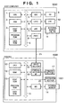
- Fig. 1 is a block diagram showing the arrangement of a printer control system according to the embodiment. As shown in Fig. 1 , the printer control system is constituted by a host computer 3000 and printer 1500.
- the present invention can be applied to a single device, a system formed from a plurality of devices, or a system connected through a network such as a LAN or WAN to execute processing as far as the function of the present invention can be implemented.
- the host computer 3000 shown in Fig. 1 has a CPU 1 which processes documents made up from graphics, images, characters, tables (including spreadsheets), and the like in a mixed manner, on the basis of a document processing program stored in the program ROM in a ROM 3 or in an external memory (HD or FD) 11.
- the CPU 1 systematically controls all devices connected to a system bus 4.
- the program ROM in the ROM 3 or the external memory 11 stores an operating system (to be referred to as an "OS" hereinafter) serving as the control program of the CPU 1.
- the font ROM in the ROM 3 or the external memory 11 stores font data to be used in document processing.
- the data ROM in the ROM 3 or the external memory 11 stores various data to be used in document processing.
- a RAM 2 functions as a main memory or work area of the CPU 1.
- a keyboard controller (KBC) 5 controls an input from a keyboard 9 or a pointing device (not shown).
- a CRT controller 6 controls display on a CRT display (CRT) 10.
- a disk controller (DKC) 7 controls access to the external memory 11 such as a hard disk (HD) or floppy disk (FD) which stores a boot program, various kinds of applications, font data, user files, edit files, and printer control command generation program (to be referred to as a "printer driver” hereinafter).
- a printer controller (PRTC) 8 executes communication control processing with the printer 1500 connected through a bidirectional interface (interface) 21.
- the CPU 1 executes, e.g., rasterizing of an outline font on a display information area set on the RAM 2 to allow WYSIWYG on the CRT 10.
- the CPU 1 also opens various kinds of registered windows on the basis of a command pointed by a mouse cursor (not shown) on the CRT 10 and executes various data processing operations. With this arrangement, in executing printing, the user can open a window related to print settings to set the printer or set the print processing method for the printer driver including selection of a print mode.
- a printer CPU 12 outputs an image signal as output information to a printing section (printer engine) 17 connected to a system bus 15 on the basis of a control program stored in the program ROM in a ROM 13 or a control program stored in an external memory 14.
- the program ROM in the ROM 13 also stores the control program of the CPU 12.
- the font ROM in the ROM 13 stores font data to be used in generating output information.
- the data ROM in the ROM 13 stores information to be used on the host computer.
- the CPU 12 can communicate with the host computer 3000 through an input section 18 so that information in the printer 1500 can be sent to the host computer 3000.
- a RAM 19 functions as the main memory or work area of the CPU 12. The memory capacity of the RAM 19 can be expanded using an optional RAM connected to an expansion port (not shown).
- the RAM 19 is used as an output information rasterizing area, environment data storage area, or NVRAM. Access to the above-described external memory 14 such as a hard disk (HD) or IC card is controlled by a memory controller (MC) 20.
- the external memory 14 is connected as an option to store font data, an emulation program, and form data.
- An operation panel 1501 is formed from switches and LED indicators for operation.
- the number of above-described external memories 14 is not limited to one. Instead, a plurality of optional cards in addition to internal fonts or a plurality of external memories which store programs for interpreting printer control languages of different language systems may be connected.
- an NVRAM (not shown) may be arranged to store print mode setting information from the operation panel 1501.
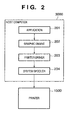
- Fig. 2 is a block diagram showing print processing executed by the host computer 3000.
- An application 201, graphic engine 202, printer driver 203, and system spooler 204 in Fig. 2 are present as files stored in the external memory 11. In executing a file as a program module, it is loaded into the RAM 2 by the OS or a module which uses the module and executed.
- the application 201 and printer driver 203 may be added to the HD of the external memory 11 through an FD of the external memory 11, a CD-ROM (not shown), or a network (not shown).
- the application 201 stored in the external memory 11 is loaded into the RAM 2 and executed.
- the application 201 outputs a print instruction to the printer 1500 by the keyboard 9 or a mouse (not shown)
- output (rendering) is performed using the graphic engine 202 which is also loaded into the RAM 2 and is executable.
- the graphic engine 202 loads the printer driver 203 prepared for each printing apparatus from the external memory 11 into the RAM 2 and sets the output from the application 201 in the printer driver 203.
- the graphic engine 202 also converts a GDI (Graphic Device Interface) function received from the application 201 into a DDI (Device Driver Interface) function and outputs it to the printer driver 203.
- GDI Graphic Device Interface
- DDI Device Driver Interface
- the printer driver 203 converts the DDI function received from the graphic engine 202 into a control command, e.g., a PDL (Page Description Language) that can be recognized by the printer 1500.
- the converted printer control command is transferred to the system spooler 204 loaded into the RAM 2 by the OS and output to the printer 1500 through the interface 21 as print data.
- Fig. 3 shows an arrangement obtained by extending the system shown in Fig. 2 , which temporarily generates a spool file 303 formed from an intermediate code in sending a print instruction from the graphic engine 202 to the printer driver 203.
- the application 201 is released from print processing when the printer driver 203 has completely converted all print instructions from the graphic engine 202 into printer control commands.
- the application 201 is released from print processing when a spooler 302 has completely converted all print instructions into intermediate code data and output them to the spool file 303. That is, according to the system shown in Fig. 3 , the application 201 is released from print processing in a short time. Additionally, in the system shown in Fig. 3 , the contents of the spool file 303 can be processed. Hence, a function that is not provided by the application, for example, a function of reducing or enlarging print data from the application 201 or reducing and printing a plurality of pages into one page, can be realized.
- the system shown in Fig. 3 is extended to spool intermediate code data.
- setting is done on a window provided by the printer driver 203, and the printer driver 203 saves the setting contents on the RAM 2 or external memory 11.
- a DDI function as a print instruction from the graphic engine 202 is received by a dispatcher 301. If the print instruction (DDI function) received from the graphic engine 202 is based on a print instruction (GDI function) issued from the application 201 to the graphic engine 202, the dispatcher 301 loads the spooler 302 stored in the external memory 11 into the RAM 2 and sends the print instruction (DDI function) not to the printer driver 203 but to the spooler 302.
- GDI function print instruction issued from the application 201 to the graphic engine 202
- the spooler 302 analyzes the received print instruction, converts the print instruction into an intermediate code for each page, and outputs the intermediate code data to the spool file 303.
- the spool file of the intermediate code stored for each page is called a PDF (Page Description File).
- the spooler 302 also acquires from the printer driver 203 process settings (bookbinding printing, Nup, double-side printing, stapling, color/monochrome, and the like) related to the print data set for the printer driver 203 and stores them in the spool file 303 as a file for each job.
- the setting file stored for each job is called a spool description file (to be referred to as an SDF).
- the spool description file will be described later in more detail.
- the spool file 303 is generated as a file on the external memory 11. However, the spool file 303 may be generated on the RAM 2.
- the spooler 302 also loads a spool file manager 304 stored in the external memory 11 into the RAM 2 and notifies the spool file manager 304 of the generation situation of the spool file 303. After that, the spool file manager 304 determines on the basis of the contents of process settings related to the print data and stored in the spool file 303 whether printing can be performed.
- a despooler 305 stored in the external memory 11 is loaded into the RAM 2 and instructed to execute print processing of a page description file of an intermediate code described in the spool file 303. Then, the despooler 305 processes the page description file of the intermediate code contained in the spool file 303 in accordance with the spool description file containing process setting information and contained in the spool file 303, re-generates a GDI function, and outputs it through the graphic engine 202 again.
- the dispatcher 301 sends the print instruction not to the spooler 302 but to the printer driver 203.
- the printer driver 203 generates a printer control command formed from a page description language on the basis of the DDI function acquired from the graphic engine 202 and outputs the command to the printer 1500 through the system spooler 204.
- a previewer 306 and setting change editor 307 are arranged to allow preview, print setting change, and combining of a plurality of jobs.
- the contents set in the property of the printer driver are stored in a structure (e.g., called DEVMODE in Windows) provided by the OS as a setting file.
- the structure contains, e.g., setting whether a file is to be stored in the spool file manager 304 during process setting contained in the spool file 303.
- a page description file and spool description file are generated and stored in the spool file 303, as described above.
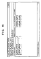
- the window of the spool file manager pops up to display a list of jobs spooled in the spool file 303.
- Fig. 16 shows an example in which four jobs are spooled.
- a menu bar 1601 or a menu icon 1602 immediately under the menu bar 1601 is clicked on, the jobs can be operated.
- the number of operations on the menu bar 1601 equals the number of operations represented by the menu icons 1602.
- the previewer 306 stored in the external memory 11 is loaded in the RAM 2 and instructed to execute preview processing of the job of the intermediate code described in the spool file 303.
- the previewer 306 sequentially reads out the page description files (PDFs) of intermediate codes contained in the spool file 303, processes the PDFs in accordance with the contents of process setting information contained in the spool description file (SDF) stored in the spool file 303, and outputs a GDI function to the graphic engine 202.
- PDFs page description files
- SDF process setting information contained in the spool description file
- the graphic engine 202 can appropriate rendering in accordance with a designated output destination.
- the previewer 306 can be implemented by processing an intermediate code contained in the spool file 303 in accordance with the contents of process setting contained in the spool file 303 and outputting the intermediate code using the graphic engine 202, like the despooler 305.
- a print preview that indicates the actual manner the rendering data is to be printed, or a print preview that is closest to the result to be output by the printer can be presented to the user in accordance with each condition, e.g., whether Nup (N logical pages are reduced and laid out in one physical page and printed) is designated, bookbinding printing is designated, or stamping is designated.
- the despooler 305 processes the page description file on the basis of the spool description file to generate a GDI function.
- the print request is transmitted to the graphic engine 202.
- the print instruction is sent to the printer driver 203 through the dispatcher 301. Then, printing is executed.
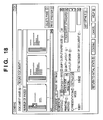
- the setting change editor 307 can be set for a job for which "edit + preview" is designated in Fig. 9 , like the preview. With similar processing, the window of the spool file manager 304 pops up to display a list of spooled jobs. When "job edit" is designated on the window of the spool file manager 304, and setting change is instructed, the setting change editor 307 stored in the external memory 11 is loaded into the RAM 2 and instructed to display current or default process settings. A job setting window as shown in Fig. 18 is displayed.
- This setting change editor 307 acquires from the spool file 303 the spool description file of a job for which "job edit" is designated, and changes the default values of the job setting window shown in Fig. 18 on the basis of set items designated in the spool description file.
- number of copies 1, print mode: single-side, layout: 1 page/sheet, and the like are designated.
- the contents of process settings contained in the spool description file stored in the spool file 303 can be changed or corrected. To do this, items that can be set by the printer driver 203 may be prepared in the user interface on the setting change editor 307. Alternatively, the user interface of the printer driver 203 itself may be invoked.
- the number of copies, print mode (single-side, double-side, bookbinding printing), page layout, arrangement order, and the like can be designated.
- print mode single-side, double-side, bookbinding printing
- page layout arrangement order, and the like.
- “detail setting” is clicked on, most of items that can be designated by the printer driver can be re-set. However, the setting change of items related to the printing quality, including resolution and graphic mode, is not permitted.
- the change is approved in accordance with the approval request on the setting change editor 307. Control shifts to the spool file manager 304.
- the change in print settings is saved. It is saved not in the original spool description file but in a newly created job output setting file used for job editing or the like. The job output setting file will be described later in detail with reference to Fig. 10 and subsequent drawings.
- the user When the user confirms the change on the previewer 306 and wants to print in accordance with the changed setting contents, he issues a print request on the spool file manager 304.
- the print request is transmitted to the graphic engine 202.
- a print instruction is sent to the printer driver 203 through the dispatcher 301. Then, printing is executed.
- designation can be done to combine a plurality of print jobs and print them as one print job.
- This designation also premises a job for which "edit + preview" is designated as an output destination in the property of the printer driver shown in Fig. 9 .
- the setting change editor 307 stored in the external memory 11 is loaded into the RAM 2 and instructed to display process settings of the first job on the list of default process settings.
- a combining setting window as shown in Fig. 18 is displayed.
- the job setting window of the setting change editor 307 is used as the combining setting window.
- another module may be used.
- This setting change editor 307 processes the page description file of the intermediate code contained in the spool file 303 in accordance with the contents of process settings contained in the job setting information stored in the spool file 303 and outputs the page description file to the client area of its own using the graphic engine 202 for all jobs designated as jobs to be combined, thereby outputting an image on the window. At this time, small previews of all jobs selected can be displayed in the preview area shown in Fig. 18 .
- a job output setting file is generated by extending the spool description file of each job. The job output setting file is generated even when job editing is executed.
- One job output setting file is generated for one job.
- one job output setting file is generated for one combined job.
- Process settings for each job before combining or those changed or corrected to process settings integrated for the combined job may be displayed.
- items that can be set by the printer driver 203 may be prepared in the user interface on the setting change editor 307.
- the user interface of the printer driver 203 itself may be invoked.
- the change is approved in accordance with the approval request on the setting change editor 307, as described above.
- Control shifts to the spool file manager 304. With these operations, the plurality of selected jobs are displayed as one combined job on the window of the spool file manager.
- the user When the user confirms the change on the previewer 306 and wants to print in accordance with the changed setting contents, he issues a print request on the spool file manager 304.
- the print request is transmitted to the graphic engine 202.
- a print instruction is sent to the printer driver 203 through the dispatcher 301. Then, printing is executed.
- the structure of the printer 1500 of this embodiment which executes printing on the basis of a printer control command input from the printer driver 203 through the system spooler 204, will be described next.
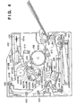
- Fig. 4 is a sectional view showing the structure of the printer of this embodiment.
- the printer 1500 a color laser printer having a double-side printing function will be described here.
- a laser beam modulated in accordance with image data of each color obtained on the basis of print data input by the host computer 3000 scans a photosensitive drum 415 through a polygon mirror 431, thereby forming an electrostatic latent image.
- This electrostatic latent image is developed by toner to obtain a visible image.
- a multiple of visible images for all colors are transferred onto an intermediate transfer body 409, thereby forming a color visible image.
- the color visible image is further transferred onto a transfer member 402 and fixed on the transfer member 402.
- An image forming section which executes the above control is constructed by a drum unit 413 having the photosensitive drum 415, a primary charging section having a contact charge roller 417, a cleaning section, a developing section, the intermediate transfer body 409, a paper feed section including a paper cassette 401 and various kinds of rollers 403, 404, 405, and 407, a transfer section including a transfer roller 410, and a fixing section 425.
- the drum unit 413 is formed by integrating the photosensitive drum (photosensitive body) 415 and a cleaner container 414 having a cleaning mechanism which also serves as the holder of the photosensitive drum 415.
- the drum unit 413 is supported to be detachable from the printer main body.
- the drum unit 413 can easily be exchanged in accordance with the service life of the photosensitive drum 415.
- the photosensitive drum 415 is formed by coating the outer surface of an aluminum cylinder with an organic photoconductive layer and rotatably supported by the cleaner container 414.
- the photosensitive drum 415 rotates upon receiving a driving force from a drive motor (not shown).
- the drive motor rotates the photosensitive drum 415 counterclockwise in accordance with image forming operation. When the surface of the photosensitive drum 415 is selectively exposed, an electrostatic latent image is formed.
- a modulated laser beam is reflected by the polygon mirror 431 which is rotated by a motor 431a in synchronism with a horizontal sync signal of an image signal so that the photosensitive drum 415 is irradiated with the laser beam through a lens 432 and reflecting mirror 433.
- the developing section has three color developing units 420Y, 420M, and 420C which develop yellow (Y), magenta (M), and cyan (C) images, and one black developing unit 421B which develops a black (B) image.
- the color developing units 420Y, 420M, and 420C and black developing unit 421B have sleeves 420YS, 420MS, 420CS, and 421BS and coating blades 420YB, 420MB, 420CB, and 421BB which are pressed against the outer surfaces of the sleeves 420YS, 420MS, 420CS, and 421BS, respectively.
- the three color developing units 420Y, 420M, and 420C have coating rollers 420YR, 420MR, and 420CR, respectively.
- the black developing unit 421B is detachably attached to the printer main body.
- the color developing units 420Y, 420M, and 420C are detachable attached to a developing rotary 423 which rotates about a rotating shaft 422.
- the sleeve 421BS of the black developing unit 421B is arranged at a small interval of, e.g., about 300 ⁇ m with respect to the photosensitive drum 415.
- the black developing unit 421B conveys toner by an internal convey member and applies electrical charges to the toner by frictional charging such that the toner is coated by the coating blade 421BB on the outer surface of the sleeve 421BS which rotates clockwise.
- a developing bias is applied to the sleeve 421BS, the electrostatic latent image is developed on the photosensitive drum 415 to form a visible image on the photosensitive drum 415 by black toner.
- the three color developing units 420Y, 420M, and 420C rotate as the developing rotary 423 rotates in forming an image.
- a predetermined one of the sleeves 420YS, 420MS, and 420CS opposes the photosensitive drum 415 at a small interval of about 300 ⁇ m.
- a predetermined one of the color developing units 420Y, 420M, and 420C stops at a developing position opposing the photosensitive drum 415, so a visible image is formed on the photosensitive drum 415.
- the developing rotary 423 rotates as the intermediate transfer body 409 rotates by one revolution.
- the developing process is executed in the order of yellow developing unit 420Y, magenta developing unit 420M, cyan developing unit 420C, and black developing unit 421B.
- yellow developing unit 420Y magenta developing unit 420M
- cyan developing unit 420C cyan developing unit 420C
- black developing unit 421B black developing unit 421B.
- the intermediate transfer body 409 is designed to come into contact with the photosensitive drum 415 and rotate as the photosensitive drum 415 rotates. In forming a color image, the intermediate transfer body 409 rotates clockwise to receive multiple transfer of four visible images from the photosensitive drum 415. Additionally, in forming a color image, the transfer roller 410 (to be described later) comes into contact with the intermediate transfer body 409 to sandwich and convey the transfer member 402, thereby simultaneously multiple-transferring the color visible images on the intermediate transfer body 409 onto the transfer member 402.
- a TOP sensor 409a and RS sensor 409b, which detect the position of the intermediate transfer body 409 in the rotational direction, and a density sensor 409c which detects the density of the toner image transferred to the intermediate transfer body 409 are arranged at the outer peripheral portion of the intermediate transfer body 409.
- the transfer roller 410 has a transfer charger supported to come close to or separate from the intermediate transfer body 409.
- the transfer roller 410 is formed by winding a medium-resistive foam elastic body around a metal shaft. While color visible images are being multiple-transferred onto the intermediate transfer body 409, the transfer roller 410 separates downward not to disturb the color visible images, as indicated by a solid line in Fig. 4 . After the four color visible images are formed on the intermediate transfer body 409, the transfer roller 410 is located at the upper position indicated by a dotted line in Fig. 4 by a cam member (not shown) in synchronism with the transfer timing of the color visible images onto the transfer member 402.
- the transfer roller 410 is pressed against the intermediate transfer body 409 by a predetermined press force via the transfer member 402. Simultaneously, a bias voltage is applied to the transfer roller 410. Hence, the color visible images on the intermediate transfer body 409 are transferred onto the transfer member 402.
- the fixing section 425 fixes the transferred color visible images while conveying the transfer member 402.
- the fixing section 425 has a fixing roller 426 for heating the transfer member 402 and a press roller 427 for pressing the transfer member 402 against the fixing roller 426.
- the fixing roller 426 and press roller 427 are hollow rollers and incorporate heaters 428 and 429, respectively. That is, the transfer member 402 which holds the color visible images is conveyed by the fixing roller 426 and press roller 427 and simultaneously heated and pressed to fix the toner on the surface of the transfer member 402.
- the transfer member 402 is discharged to a discharge section 437 by discharge rollers 434, 435, and 436. Thus, the image forming operation is ended.
- the cleaning means cleans the toner that remains on the photosensitive drum 415 and intermediate transfer body 409. Waste toner that remains after a visible image formed on the photosensitive drum 415 by toner is transferred onto the intermediate transfer body 409 or waste toner that remains after four color visible images formed on the intermediate transfer body 409 are transferred onto the transfer member 402 is stored in the cleaner container 414.
- the transfer member (printing paper sheet) 402 to be printed is picked up from the paper feed tray 401 by the paper feed roller 403.
- Color toner images are printed on the printing paper sheet which is sandwiched between the intermediate transfer body 409 and the transfer roller 410 and conveyed.
- the toner images are fixed.
- a convey path is formed such that a guide 438 guides the printing paper sheet to the discharge section 437 on the upper side.
- a path is formed to guide the printing paper sheet to a double-side printing unit on the lower side.
- the printing paper sheet guided to the double-side printing unit is temporarily sent to the lower side of the tray 401 (convey path indicated by a chain double-dashed line) by a convey roller 440 and then conveyed in a reverse direction to a double-side tray 439.
- the paper sheet On the double-side tray 439, the paper sheet is turned over from those placed in the paper cassette 401.
- the convey direction is also reversed. In this state, toner images are transferred and fixed again, thereby completing double-side printing.
- Fig. 5 is a flow chart showing a generation process by the spooler 302.
- the spooler 302 receives a print request from the application 201 through the graphic engine 202 and dispatcher 301.
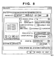
- a dialogue for inputting print settings as shown in Fig. 8 is displayed. Print settings input from this dialogue are transferred to the spooler 302 through the printer driver 203.
- the setting input dialogue shown in Fig. 8 includes a setting item for determining the number of logical pages to be laid out in one physical page, as indicated by 801.
- step S502 the spooler 302 determines whether the received print request is a job start request. If YES in step S502, the flow advances to step S503.
- the spooler 302 generates the spool file 303 to temporarily store intermediate data.
- step S504 the spooler 302 notifies the spool file manager 304 of the progress of print processing.
- step S505 the page counter of the spooler 302 is initialized to "1".
- the spool file manager 304 loads and stores, from the spool file 303, job setting information and process settings for the job that has started printing.
- step S502 determines whether the received request is a job end request. If NO in step S506, the flow advances to step S507 to determine whether page feed is designated. If YES in step S507, the flow advances to step S508 to notify the spool file manager 304 of the progress of print processing, increment the page counter by one, close the page description file that stores the intermediate code, and generate the next page description file.
- step S509 The spooler 302 prepares for a write of the intermediate code in a page description file.
- step S510 to store the print request in the spool file 303, the spooler 302 converts the DDI function of the print request into an intermediate code.
- step S511 the spooler 302 writes the print request (intermediate code) converted into a storable form in step S510 in the page description file of the spool file 303.
- the flow returns to step S501 to receive a print request from the application 201 again.
- step S501 to S511 The series of processes in steps S501 to S511 are continued until a job end request (End Doc) is received from the application 201.
- the spooler 302 acquires pieces of information such as process settings stored in a DEVMODE structure from the printer driver 203 and stores them in the spool file 303 as a spool description file. If YES in step S506, the flow advances to step S512 because all print requests from the application 201 are ended.
- the spool file manager 304 is notified of the progress of print processing, and the processing is ended.
- a process for causing the spool file manager 304 to receive progress notification from the spooler 302 or despooler 305 and control the generation process by the spooler 302 and a print data generation process (to be described later) by the despooler 305 will be described next.
- Fig. 6 is a flow chart showing control by the spool file manager 304.
- the spool file manager 304 receives a print processing progress notification from the spooler 302 or despooler 305.
- the spool file manager 304 determines whether the progress notification is a printing start notification from the spooler 302, which is sent in step S504 of Fig. 5 . If YES in step S602, the flow advances to step S603 to load process settings for printing from the spool file 303 and start managing a job.
- step S602 determines whether the progress notification is a notification of the end of printing (page feed) of one logical page, which is sent from the spooler 302 in step S508 of Fig. 5 . If YES in step S604, the flow advances to step S605 to store logical page information corresponding to the logical page. It is determined in step S606 whether printing of one physical page can start for n logical pages that have been spooled. If YES in step S606, the flow advances to step S607 to determine the physical page number from the number of logical pages assigned to one physical page to be printed.
- a process setting is done to lay out, e.g., four logical pages in one physical page, as shown in Fig. 8 .
- the first physical page can be printed when the fourth logical page is spooled.
- the second physical page can be printed when the eighth logical page is spooled.
- logical pages to be laid out in one physical page can be determined by the spool end notification in step S512 of Fig. 5 .
- step S608 pieces of information including the numbers of logical pages that construct the printable physical page and the physical page number are stored in a job output setting file (a file containing physical page information) by a format as shown in Fig. 10 .
- the despooler 305 is notified that physical page information corresponding to one physical page is added. After that, the flow returns to step S601 to wait for the next notification.
- the job output setting file will be described later in more detail with reference to Fig. 10 .
- print processing can be performed when logical pages that construct one physical page are spooled.
- step S604 determines whether the notification is a job end notification from the spooler 302, which is sent in step S512 of Fig. 5 . If YES in step S609, the flow advances to step S606 described above. If NO in step S609, the flow advances to step S610.
- the spool file manager 304 determines whether the received notification is a printing end notification of one physical page from the despooler 305. If YES in step S610, the flow advances to step S611 to determine whether printing for the process settings is completed. If YES in step S611, the flow advances to step S612 to notify the despooler 305 of the end of printing. If NO in step S611, the flow advances to step S606 described above.
- the despooler 305 of this embodiment presumes one physical page as a unit of print processing.
- step S608 described above pieces of information necessary for print processing of one physical page are successively stored in a file such that they can be reused. If reuse is unnecessary, a high-speed medium such as a shared memory may used to sequentially overwrite information for each physical page so as to increase the speed and save the resource.
- the speed of progress of the spooler 302 is higher than that of the despooler 305, or if the despooler 305 starts after all pages are spooled, the despooler 305 need not always be notified of the page printable state for each physical page in step S608. Instead, in accordance with the progress on the despooler 305 side, the despooler 305 may be notified that a plurality of physical pages or all physical pages are printable such that the number of times of notification can be decreased.
- step S610 the flow advances to step S613.
- the spool file manager 304 determines whether the notification is a printing end notification from the despooler 305. If YES in step S613, the flow advances to step S614.
- the spool file manager 304 deletes the corresponding page description file of the spool file 303, and the processing is ended. If NO in step S613, the flow advances to step S615 to execute another normal processing (e.g., error processing) and wait for the next notification.
- a print data generation process of causing the despooler 305 to read out necessary information (page description file, spool description file, and the like) from the spool file 303 in accordance with a print request from the spool file manager 304 and generates print data will be described next.
- the method of transferring generated print data to the printer 1500 is the same as that described with reference to Fig. 3 .
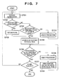
- Fig. 7 is a flow chart showing the print data generation process by the despooler 305.
- step S701 a notification from the spool file manager 304 is received.
- step S702 the despooler 305 determines whether the received notification is a job end notification. If YES in step S702, the flow advances to step S703 to set an end flag. The flow then advances to step S705.
- step S704 determines whether the notification if a printing start request for one physical page, which is sent in step S608 of Fig. 6 . If NO in step S704, the flow advances to step S710 to execute another processing (error processing). The flow returns to step S701 to wait for the next notification. If YES in step S704, the flow advances to step S705.
- the despooler 305 stores the ID of the printable physical page that is received in step S704.
- step S706 determines whether print processing of all pages for the physical page IDs stored in step S705 is ended. If YES in step S706, the flow advances to step S707 to determine whether the end flag has been set in step S703.
- step S707 it is regarded that the job is ended.
- the spool file manager 304 is notified that the processing by the despooler 305 is ended, and the processing is ended. If NO in step S707, the flow returns to step S701 to wait for the next notification.
- step S706 the flow advances to step S708.
- the despooler 305 sequentially reads out unprocessed physical page IDs from the stored physical page IDs.
- the despooler 305 loads information necessary for generating print data of a physical page corresponding to each readout physical page ID and executes print processing.
- the despooler 305 converts the print request instruction stored in the spool file 303 into a format (GDI function) that can be recognized by the graphic engine 202 and transfers the GDI function.
- step S708 For a process setting (to be referred to as "N page printing” hereinafter) for laying out a plurality of logical pages in one physical page, the print request instruction is converted in step S708 in consideration of reduction layout.
- the spool file manager 304 is notified of the end of print data generation for one physical page in step S709. The flow returns to step S706. These processes are repeated until print processing for all printable physical page IDs stored in step S705 described above is ended.
- the application 201 is released from print processing at a timing when the spooler 302 generates an intermediate code and stores it in the spool file 303.
- the processing time can be shortened as compared to conventional print processing in which print data is directly output to the printer driver 203.
- an intermediate file (page description file and spool description file) which takes print settings of the printer driver into consideration is temporarily stored in the spool file 303.
- the user can recognize a print preview to be actually printed.
- print jobs generated by a plurality of applications 201 can be combined or rearranged. Print settings can be changed by the user without activating the application 201 again to execute printing.
- a job output setting file is generated by the despooler 305 when a print request is issued to the graphic engine 202. Even when preview or job combining is performed, a job output setting file is generated.
- This job output setting file is the same as a spool description file for a single job. For a combined job, the job output setting file is generated on the basis of a plurality of pieces of job setting information.
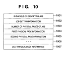
- Fig. 10 is a view showing a job output setting file in this embodiment.
- This job output setting file stores information of a printable physical page generated by the spool file manager 304 in step S608 of Fig. 6 .
- an ID used to identify a job is stored in a field 1001.
- the ID may be held in a form such as the name of a file that stores the information or the name of a shared memory.
- Job setting information is stored in a field 1002.
- the job setting information contains a structure necessary for starting printing the job for the graphic engine 202, designation of N page printing, designation of additional rendering of a page frame or the like, the number of copies, and finishing designation such as stapling. These pieces of information can be set only in a one-to-one correspondence to a job. In the job setting information, only necessary pieces of information are stored in accordance with the function to the job.
- the number of physical pages of the job is stored in a field 1003, which indicates that pieces of physical page information corresponding to the number are stored after this field.
- the field 1003 since a notification of the number of printable physical pages is sent, the field 1003 may be omitted. After this field, pieces of physical page information corresponding to the number of physical pages stored in the field 1003 are stored from a field 1004. The physical page information will be described later in more detail with reference to Fig. 12 .
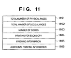
- Fig. 11 is a view showing job setting information in the field 1002 shown in Fig. 10 .
- the total number of physical pages is stored in a field 1101.
- the total number of logical pages is stored in a field 1102.
- the information in the fields 1101 and 1102 can be added to print data and used when, e.g., the number of pages is printed as additional information. While printing continues, these fields store temporary values. Alternatively, until printing is ended, the spool file manager 304 postpones generating information of printable physical pages.
- Information of the number of copies which designates the number of copies to be printed by a print job, is stored in a field 1103.
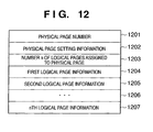
- Fig. 12 is a view showing physical page information in the field 1004 shown in Fig. 10 .
- a physical page number is stored in a first field 1201. That is, a value used to manage the printing order or additionally print a physical page number is stored.
- Physical page setting information is stored in a field 1202. When layout or a color/monochrome mode can be designated for each physical page, the setting of layout or a color/monochrome mode is stored.
- the number of logical pages assigned to a physical page is stored in a field 1203. When four pages are assigned to one physical page, "4" or an ID that indicates 4-page printing is stored. Pieces of logical page information corresponding to the number designated in the field 1203 are stored from a field 1204.
- the actual number of page data is smaller than the number of pages designated in the field 1203 because of the number of pages printed from the application 201.
- special data that indicates a blank page is stored as logical page information.
- Fig. 13 is a view showing physical page setting information in the field 1202 shown in Fig. 12 .
- the layout order of logical pages on a physical page is stored in a field 1301.
- designation of the order of laying out logical pages on a physical page e.g., rightward or downward from the upper left
- the pieces of logical page information from the field 1204 are arranged not in the order of page number but in an order corresponding to the layout order as a substitute for the setting in the field 1301.
- Information representing an upper or lower surface in the double-side print mode is stored in a field 1302.
- This information is used to, e.g., align the binding margin on the upper and lower surfaces.
- Designation of a color page or monochrome page is stored in a field 1303. This information is used when the printer has a monochrome mode and color mode, and a document made up from both color and monochrome pages is to be printed by printing a color page in the color mode and a monochrome page in the monochrome mode.
- processing by a color printer can be changed for each page in an auto-color mode. More specifically, for a color page, the intermediate transfer body (intermediate transfer drum and intermediate transfer belt) or transfer member rotates by the number of device colors, i.e., four revolution for YMCK.
- the intermediate transfer body or transfer member rotates by only one revolution for black, thereby controlling transfer.
- Additional printing information is stored in a field 1304. This information is used when additional information such as the number of pages or the date is to be printed on a physical page.
- fields are added in accordance with the function of the system.
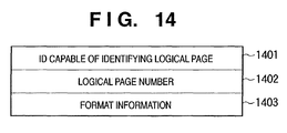
- Fig. 14 is a view showing logical page information in the field 1204 shown in Fig. 12 .
- the ID of a logical page is stored in a field 1401.
- the intermediate code of a page description file corresponding to the logical page is referred to from the spool file 303 using this ID.
- the intermediate code of the logical page only needs to be accessible using the ID.
- a file, a memory pointer, or the intermediate code itself of the logical page may be included.
- a logical page number is stored in a field 1402.
- the logical page number is used when it is to be printed as additional information or as supplementary information of the logical page ID.
- Format information is stored in a field 1403.
- Various setting items that can be designated for each logical page are stored.
- additional print information such as a page frame and information of various settings designated for each logical page, such as an enlargement/reduction magnification, are stored.
- Attribute information for a logical page such as color/monochrome information for each logical page can also be stored as needed.
- the field 1403 can be omitted in a system which requires no change in settings for each logical page or no attribute information for each logical page.
- a job output setting file has the above-described structure.
- a spool description file has almost the same structure as described above. More specifically, a spool description file has, as a job, a print format (single- or double-side print mode, bookbinding printing, or the like), print layout (Nup or poster printing), additional information (additional digital watermark, date, or user name), the number of copies, and paper size information.
- a print format single- or double-side print mode, bookbinding printing, or the like
- print layout Non-back printing
- additional information additional digital watermark, date, or user name
- the number of copies and paper size information.
- Each physical page is formed from a layout order of logical pages, information representing an upper or lower surface in the double-side print mode, and a color mode.
- the setting contents of a job are contained in a spool description file for a single job or in a job output setting file shown in Fig. 10 for a combined job. Since the file is separated from the spool file 303 that stores an intermediate code, the job settings can be changed by re-creating the job output setting file.
- the setting change editor 307 re-creates or partially rewrites a job output setting file independently or in cooperation with the spool file manager 304, thereby realizing the job setting change function.
- Fig. 15 is a flow chart showing a job setting change process by the setting change editor 307.
- the setting change editor 307 loads a spool description file or job output setting file.
- the job output setting file is the same as that loaded by the previewer 306 or despooler 305.
- the contents of the loaded file are displayed for the user.
- the setting contents are changed by interaction with the user on the user interface as shown in Fig. 18 and designating the menu or the like as described above. In this step, not the interaction scheme but a batch scheme of changing the contents in accordance with the contents of setting change written in a file or the like may be employed.
- step S1504 the setting change editor 307 compares the setting contents loaded first in step S1501 with the current setting contents and determines whether the setting contents are changed. If YES in step S1504, the flow advances to step S1505 to generate a new job output setting file and notify the spool file manager 304 that the setting contents are changed. The processing is ended. If NO in step S1504, the spool file manager 304 is notified that the setting contents are kept unchanged, and the processing is ended.
- a new job output setting file is generated.
- the new job output setting file is validated, and the old job output setting file is deleted.
- the file is saved without being deleted.
- the new job output setting file is deleted, and the old job output setting file is validated and reflected on display.
- the setting change editor 307 has been described as another module. However, the setting change editor 307 may merely be part of the user interface of the spool file manager 304. In addition, instead of causing the setting change editor 307 to actually write the change contents in the job output setting file, the setting change editor 307 may notify the spool file manager 304 of only the contents of setting change, and the job output setting file may be actually changed on the spool file manager 304 side.
- the spool file 303 with the intermediate code format is normally generated for each job.
- the intermediate code of each logical page in a job file to be processed is sequentially read out and processed.
- the logical page ID in the field 1401 can be realized by a relative or absolute offset that indicates the location of each logical page in the file.
- the spool file 303 and page information belonging to the job must be specified from the job ID in the field 1401.
- an ID for identifying the spool file 303 is added to a logical page ID, thereby specifying the spool file 303. In this case, only the field 1401 needs to be mainly changed.
- the spool file 303 can be identified in the field 1401, loading a page portion can be processed by the same logic as in processing of a single job.
- the file name of each logical page may be used as a logical page ID in the field 1401.
- the above-described job binder function makes it possible to continuously transmit PDL data as a plurality of documents between commands that designate the start and end of one print job transmitted from the printer driver 203 to the printer 1500.
- Fig. 19 is a view showing the user interface of the printer driver 203 which designates a print mode in which a single original is printed in accordance with a plurality of print settings.
- a check box of "presentation mode” is checked on this user interface, the presentation function of printing OHP films for presentation and materials to be distributed all at once is validated.
- a "detail setting button” 1902 in the presentation mode is validated. When the button is clicked on, a dialogue shown in Fig. 20 is activated.
- the above-described user interface is displayed by a display control module (also called a display control means) contained in the printing control program of the present invention.
- a display control module also called a display control means
- details for the presentation mode can be set.
- the user interface of the printer driver 203 has the same set items as those settable in this user interface of the presentation mode. Settings on the user interface of the printer driver 203 are applied to materials to be distributed. Settings of the above-described dialogue are applied to OHP films.
- set items include paper type 2001, color print mode 2002, output paper size 2003, number 2004 of copies, page layout 2005, printing method 2006, discharge method 2007, and discharge destination 2008. Printing of OHP films for presentation is assumed here.
- the default values of the respective settings are "OHP film” as the paper type 2001, "color” or “automatic discrimination” for a color printer as the color print mode 2002, "same as original size” as the output paper size 2003, “1” as the number 2004 of copies, “1 page/sheet (standard)” as the page layout 2005, “single-side printing” as the printing method 2006, and a discharge destination to which OHP films can be discharged as the discharge destination 2008.
- OHP films Since these settings can be changed on this dialogue, for example, not OHP films but paper sheets may used to output even for presentation, or N-up printing may be executed. Setting on the dialogue is done independently of setting for the materials to be distributed, OHP films may be printed in the color mode while materials to be distributed may be printed in the monochrome mode.
- the spooler 302 stores process settings for the job in the spool description file of the spool file 303, as described above.
- the spooler 302 also stores settings for OHP films for presentation, which are set in the user interface shown in Fig. 20 in the spool file 303 in the form of a spool description file. That is, when the presentation mode is set, a spool description file for OHP films of presentation and a spool description file for paper materials to be distributed are stored.
- the detail setting button 1802 When the detail setting button 1802 is clicked on, the same dialogue as the detail setting dialogue for the presentation mode, which is arranged on the user interface of the printer driver 203 shown in Fig. 20 , is displayed.
- the set contents for the OHP materials for presentation can be confirmed or changed.
- the contents displayed on this dialogue are read out from the spool description file for OHP materials for presentation, which is stored in the spool file 303. If the contents are changed, the change is stored in a job output setting file, as described above.
- two job output setting files are stored. That is, a job output setting file for OHP materials for presentation and that for paper materials to be distributed are stored. However, when a job output setting file has already been generated, the dialogue is displayed on the basis of the contents of this job output setting file.
- the combo-box for selecting the preview subject is designed to select OHP materials for presentation or paper materials to be distributed.
- Fig. 21 is a view showing a job setting window when "distribution" is selected in the preview subject selection combo-box 2103.
- materials to be distributed which have a layout of 2 pages/sheet on both surfaces, are previewed.
- the necessary number of sheets is 7.
- the contents of a spool description file corresponding to the paper materials to be distributed are displayed here. However, if a job output setting file has already been generated, preview display is done on the basis of the contents of the job output setting file.
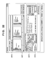
- Fig. 22 is a view showing a job setting window when "presentation" is selected in the preview subject selection combo-box 2204.
- materials for presentation which have a layout of 1 page/sheet on a single surface, are previewed.
- the necessary number of sheets is 27.
- print settings 2203 such as the number of copies, printing method, and layout indicate set values for distribution. Only the small preview area 2201 is changed for presentation.
- preview display is done on the basis of the contents of a spool description file corresponding to OHP materials for presentation, which is stored in the spool file 303.
- display is done on the basis of the contents of a spool description file corresponding to paper materials to be distributed. If a job output setting file has already been generated, both display for presentation and display for distribution are done on the basis of the contents of the job output setting file.
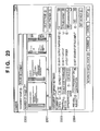
- Fig. 23 is a view showing a job setting window when "presentation/distribution" is selected in the preview subject selection combo-box 2304.
- materials for presentation which have a layout of 1 page/sheet on a single surface, and materials to be distributed, which have a layout of 2 pages/sheet on both surfaces, are previewed.
- the necessary numbers of OHP films and sheets are 27 and 7, respectively.
- print settings 2303 such as the number of copies, printing method, and layout indicate set values for distribution. Only the small preview area 2301 is changed for presentation/distribution.
- this display for presentation/distribution in addition to the display for presentation based on the contents of a spool description file corresponding to OHP materials for presentation, which is stored in the spool file 303, the contents of a spool description file corresponding to paper materials to be distributed are displayed. However, if a job output setting file has already been generated, the preview of paper materials to be distributed is displayed on the basis of the contents of the job output setting file. For the remaining display items, display is done on the basis of the contents of a spool description file corresponding to paper materials to be distributed. If a job output setting file has already been generated, both display for presentation and display for distribution are done on the basis of the contents of the job output setting file.
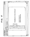
- the user interface of the large preview shown in Fig. 17 has no control function of switching the preview subject.
- the preview subject can be switched and previewed like a job setting window.
- Fig. 24 is a chart showing print processing by the despooler 305 and printer driver 203 in the presentation mode.
- the despooler 305 executes processing of generating a print job, e.g., CreateDC() or StartDoc() for Windows in accordance with a print processing procedure of the OS.
- the printer driver 203 is notified of this processing through a GDI.
- the printer driver 203 executes job generation processing and job attribute setting processing for the printer 1500. More specifically, a command for instructing generation of a job and a command for designating the attribute of the job to the printer 1500 are generated and transmitted to the printer 1500 through an OS procedure for transmitting data to the printer 1500.
- the despooler 305 executes ExtEscape (DOCUMENT_START) to notify the printer driver 203 of the start of a document having the first print settings. More specifically, it means a notification of the start of printing of an OHP portion for presentation.
- ExtEscape DOCUMENT_START
- the printer driver 203 is notified of print settings for the first document. More specifically, the printer driver 203 is notified of print settings for OHP materials for presentation.
- the printer driver 203 executes document generation processing and document attribute setting processing of notifying the printer 1500 of the start of the first document. More specifically, a command for designating print settings for the OHP materials for presentation to the printer 1500 is generated and transmitted to the printer 1500 through an OS procedure for transmitting data to the printer 1500.
- the despooler 305 notifies the printer driver 203 of the rendering contents of the first document, i.e., the rendering contents of the OHP materials for presentation through the GDI.
- the printer driver 203 receives the rendering contents that are converted from the GDI to a DDI, converts the DDI into a rendering instruction in a form such as a PDL that can be interpreted by a printer, and transmits the instruction to the printer 1500.
- the despooler 305 notifies the spooler 302 by ExtEscape (DOCUMENT_END) and ExtEscape (DOCUMENT_START) that the first document is ended, and the second document is to be started. Since the two notifications aim at notifying the printer driver 203 of the boundary between the documents, they may be made up into one notification for notifying the printer driver 203 of the boundary between the documents.
- the despooler 305 executes processing for the second document, i.e., the paper materials to be distributed, like processing for the first document.
- This processing is the same as that for the first document except that notifications of print settings and rendering contents are related to the paper materials to be distributed.
- the despooler 305 executes processing of ending the print job, e.g., EndDoc() for Windows, in accordance with the print processing procedure of the OS.
- the printer driver 203 is notified of this processing through the GDI.
- the printer driver 203 executes job ending processing. More specifically, a command for instructing the printer 1500 to end the job is generated and transmitted to the printer 1500 through an OS procedure for transmitting data to the printer 1500.
- a print job generated in the presentation mode sets a plurality of print settings (for presentation and for distribution) for a single document.
- the plurality of print settings can be transmitted from the printer driver 203 to the printer 1500 as one print job using the job binder function (protocol).
- a print job which applies a plurality of print settings to a single original can be previewed.
- the printing result can be confirmed on a screen in advance before execution of printing.
- a plurality of settings such as layout can be changed while confirming the preview result.
- the present invention may be applied to a system constituted by a plurality of devices (e.g., a host computer, an interface device, a reader, a printer, and the like) or an apparatus comprising a single device (e.g., a copying machine, a facsimile apparatus, or the like).
- a host computer e.g., a host computer, an interface device, a reader, a printer, and the like
- an apparatus comprising a single device e.g., a copying machine, a facsimile apparatus, or the like.
- the object of the present invention can also be achieved by supplying a storage medium which stores software program codes for implementing the functions of the above-described embodiment to a system or apparatus and causing the computer (or a CPU or MPU) of the system or apparatus to read out and execute the program codes stored in the storage medium.
- the program codes read out from the storage medium implement the functions of the above-described embodiment by themselves, and the storage medium which stores the program codes constitutes the present invention.
- the storage medium for supplying the program codes for example, a floppy disk, hard disk, optical disk, magnetooptical disk, CD-ROM, CD-R, magnetic tape, nonvolatile memory card, ROM, or the like can be used.
- a printing result on each output medium or printing results on a plurality of output media can be previewed before printing is executed in accordance with the print settings for each output medium.
Description
- The present invention relates to a printing control apparatus, and a display method, program, and storage medium therefor.
- When presentation is to be done using an overhead projector (OHP), routine operation may occur in which one copy of an original is printed on an OHP film for presentation, and a necessary number of copies are printed on paper sheets to be distributed. In such case, the following procedure is generally used. That is, the original is created by an information processing apparatus such as a personal computer. One copy of an output for the OHP is printed on a paper sheet by an output apparatus such as a printer. The printed original is copied to an OHP film by a copying machine. Additionally, the number of copies, layout, single- or double-side print mode, and staple are set for distribution, OHP output is changed to paper output, and the original is copied.
- Recently, a personal computer and printer can be connected. Printers capable of stapling or printing on an OHP film as an output medium are becoming popular. Hence, the user can execute the operation only by a personal computer and printer without using any copying machine. In such operation using a personal computer and printer, first, an original is created on the host computer. An OHP output for presentation is printed by directly designating for the printer an OHP film as an output medium. Next, the print settings can be changed to print the original on paper sheets to be distributed.
- In the prior art, when a plurality of different printing layouts (OHP output for presentation and paper output for distribution) are to be set for a single original created by an information processing apparatus, and the original is to be printed by an output apparatus, results by the respective printing layouts should be checked by displaying previews on a screen in advance before actual printing is executed. However, the conventional preview function is not designed to select one of the plurality of different printing layouts or a combination of a plurality of different printing layouts and display its printing result. The function is not designed to confirm the printing results displayed as previews and change settings for each printing layout.
-
EP 1 026 577 discloses an output management system which provides a nearly continuous output of raster data to a plurality of output devices, such as imagesetters, platesetters, on-press imagers, digital proofers, digital colour printers and the like. A preview system provides access to the jobs in a job list for user review on a computer monitor. - The present invention has been made to address the above problems, and has as its object to provide a printing control apparatus capable of, in printing a single original on a plurality of output media, previewing a printing result for each output medium or a printing result for a combination of a plurality of printing media before printing is executed in accordance with print settings for each output medium, and a display method, program, and storage medium for the printing control apparatus.
- The present invention provides a printing control apparatus according to
claim 1. - The present invention also provides a display method for a printing control apparatus according to
claim 3. - The present invention further provides a program according to
claim 5 and a computer-readable recording medium according toclaim 6. - Other features and advantages of the present invention will be apparent from the following description of an embodiment of the invention which is described by way of example only in conjunction with the accompanying drawings, in which like reference characters designate the same or similar parts throughout the figures thereof, and in which:
-
Fig. 1 is a block diagram showing the arrangement of a printer control system according to the embodiment; -
Fig. 2 is a block diagram showing print processing executed by ahost computer 3000; -
Fig. 3 is a block diagram showing an arrangement for temporarily spooling a printing instruction from an application by intermediate code data; -
Fig. 4 is a sectional view showing the structure of a printer according to the embodiment; -
Fig. 5 is a flow chart showing a generation process by aspooler 302; -
Fig. 6 is a flow chart showing control by aspool file manager 304; -
Fig. 7 is a flow chart showing a print data generation process by adespooler 305; -
Fig. 8 is a view showing a dialogue for inputting print settings; -
Fig. 9 is a view showing the property window of a printer driver; -
Fig. 10 is a view showing a job output setting file in the embodiment; -
Fig. 11 is a view showing job setting information in afield 1002 shown inFig. 10 ; -
Fig. 12 is a view showing physical page information in afield 1004 shown inFig. 10 ; -
Fig. 13 is a view showing physical page setting information in afield 1202 shown inFig. 12 ; -
Fig. 14 is a view showing logical page information in afield 1204 shown inFig. 12 ; -
Fig. 15 is a flow chart showing a job setting change process by asetting change editor 307; -
Fig. 16 is a view showing the window of the spool file manager; -
Fig. 17 is a view showing large preview of print process settings contained in aspool file 303; -
Fig. 18 is a view showing a job setting window; -
Fig. 19 is a view showing the user interface of a printer driver which designates a print mode in which a single original is printed in accordance with a plurality of print settings; -
Fig. 20 is a view showing the detail setting dialogue of a presentation mode; -
Fig. 21 is a view showing a job setting window when "distribution" is selected in a preview subject selection combo-box 2103; -
Fig. 22 is a view showing a job setting window when "presentation" is selected in a preview subject selection combo-box 2204; -
Fig. 23 is a view showing a job setting window when "presentation/distribution" is selected in a preview subject selection combo-box 2304; and -
Fig. 24 is a chart showing print processing by thedespooler 305 andprinter driver 203 in a presentation mode. - The embodiment of the present invention will be described below in detail with reference to the accompanying drawings.
- Before the description of this embodiment, the arrangement of a system formed from a printer to which the present invention can be applied and an information processing apparatus such as a personal computer connected to the printer and, more particularly, a printing system having a spooler serving as a spool means for, before print data to be transmitted to a printer is generated, temporarily storing the print data using a data format (so-called intermediate code) different from that of print data to be finally sent to a printer, a despooler serving as a despool means for generating the print data to be finally sent to the printer from the data temporarily stored in the intermediate code format, and a printer driver serving as a means for generating a printer control command will be described.
-
Fig. 1 is a block diagram showing the arrangement of a printer control system according to the embodiment. As shown inFig. 1 , the printer control system is constituted by ahost computer 3000 andprinter 1500. - The present invention can be applied to a single device, a system formed from a plurality of devices, or a system connected through a network such as a LAN or WAN to execute processing as far as the function of the present invention can be implemented.
- The
host computer 3000 shown inFig. 1 has aCPU 1 which processes documents made up from graphics, images, characters, tables (including spreadsheets), and the like in a mixed manner, on the basis of a document processing program stored in the program ROM in aROM 3 or in an external memory (HD or FD) 11. TheCPU 1 systematically controls all devices connected to asystem bus 4. The program ROM in theROM 3 or theexternal memory 11 stores an operating system (to be referred to as an "OS" hereinafter) serving as the control program of theCPU 1. The font ROM in theROM 3 or theexternal memory 11 stores font data to be used in document processing. The data ROM in theROM 3 or theexternal memory 11 stores various data to be used in document processing. ARAM 2 functions as a main memory or work area of theCPU 1. - In the
host computer 3000, a keyboard controller (KBC) 5 controls an input from akeyboard 9 or a pointing device (not shown). ACRT controller 6 controls display on a CRT display (CRT) 10. A disk controller (DKC) 7 controls access to theexternal memory 11 such as a hard disk (HD) or floppy disk (FD) which stores a boot program, various kinds of applications, font data, user files, edit files, and printer control command generation program (to be referred to as a "printer driver" hereinafter). A printer controller (PRTC) 8 executes communication control processing with theprinter 1500 connected through a bidirectional interface (interface) 21. - The
CPU 1 executes, e.g., rasterizing of an outline font on a display information area set on theRAM 2 to allow WYSIWYG on theCRT 10. TheCPU 1 also opens various kinds of registered windows on the basis of a command pointed by a mouse cursor (not shown) on theCRT 10 and executes various data processing operations. With this arrangement, in executing printing, the user can open a window related to print settings to set the printer or set the print processing method for the printer driver including selection of a print mode. - On the other hand, in the
printer 1500, aprinter CPU 12 outputs an image signal as output information to a printing section (printer engine) 17 connected to asystem bus 15 on the basis of a control program stored in the program ROM in aROM 13 or a control program stored in anexternal memory 14. The program ROM in theROM 13 also stores the control program of theCPU 12. The font ROM in theROM 13 stores font data to be used in generating output information. When the printer has noexternal memory 14 such as a hard disk, the data ROM in theROM 13 stores information to be used on the host computer. - The
CPU 12 can communicate with thehost computer 3000 through aninput section 18 so that information in theprinter 1500 can be sent to thehost computer 3000. ARAM 19 functions as the main memory or work area of theCPU 12. The memory capacity of theRAM 19 can be expanded using an optional RAM connected to an expansion port (not shown). - The
RAM 19 is used as an output information rasterizing area, environment data storage area, or NVRAM. Access to the above-describedexternal memory 14 such as a hard disk (HD) or IC card is controlled by a memory controller (MC) 20. Theexternal memory 14 is connected as an option to store font data, an emulation program, and form data. Anoperation panel 1501 is formed from switches and LED indicators for operation. - The number of above-described
external memories 14 is not limited to one. Instead, a plurality of optional cards in addition to internal fonts or a plurality of external memories which store programs for interpreting printer control languages of different language systems may be connected. In addition, an NVRAM (not shown) may be arranged to store print mode setting information from theoperation panel 1501. - Typical print processing executed by the host computer to which a printing apparatus such as a printer is connected directly or through a network will be described next.
-
Fig. 2 is a block diagram showing print processing executed by thehost computer 3000. Anapplication 201,graphic engine 202,printer driver 203, andsystem spooler 204 inFig. 2 are present as files stored in theexternal memory 11. In executing a file as a program module, it is loaded into theRAM 2 by the OS or a module which uses the module and executed. Theapplication 201 andprinter driver 203 may be added to the HD of theexternal memory 11 through an FD of theexternal memory 11, a CD-ROM (not shown), or a network (not shown). - First, the
application 201 stored in theexternal memory 11 is loaded into theRAM 2 and executed. When theapplication 201 outputs a print instruction to theprinter 1500 by thekeyboard 9 or a mouse (not shown), output (rendering) is performed using thegraphic engine 202 which is also loaded into theRAM 2 and is executable. - The
graphic engine 202 loads theprinter driver 203 prepared for each printing apparatus from theexternal memory 11 into theRAM 2 and sets the output from theapplication 201 in theprinter driver 203. Thegraphic engine 202 also converts a GDI (Graphic Device Interface) function received from theapplication 201 into a DDI (Device Driver Interface) function and outputs it to theprinter driver 203. - The
printer driver 203 converts the DDI function received from thegraphic engine 202 into a control command, e.g., a PDL (Page Description Language) that can be recognized by theprinter 1500. The converted printer control command is transferred to thesystem spooler 204 loaded into theRAM 2 by the OS and output to theprinter 1500 through theinterface 21 as print data. - The printing system of this embodiment will be described. In this embodiment, in addition to the printing system formed from the printer and host computer shown in
Fig. 2 , an arrangement for temporarily spooling print data from an application by intermediate code data is added, as shown inFig. 3 . -
Fig. 3 shows an arrangement obtained by extending the system shown inFig. 2 , which temporarily generates aspool file 303 formed from an intermediate code in sending a print instruction from thegraphic engine 202 to theprinter driver 203. - In the system shown in
Fig. 2 , theapplication 201 is released from print processing when theprinter driver 203 has completely converted all print instructions from thegraphic engine 202 into printer control commands. - In the system shown in
Fig. 3 , however, theapplication 201 is released from print processing when aspooler 302 has completely converted all print instructions into intermediate code data and output them to thespool file 303. That is, according to the system shown inFig. 3 , theapplication 201 is released from print processing in a short time. Additionally, in the system shown inFig. 3 , the contents of thespool file 303 can be processed. Hence, a function that is not provided by the application, for example, a function of reducing or enlarging print data from theapplication 201 or reducing and printing a plurality of pages into one page, can be realized. - Unlike the system shown in
Fig. 2 , the system shown inFig. 3 is extended to spool intermediate code data. To process print data, normally, setting is done on a window provided by theprinter driver 203, and theprinter driver 203 saves the setting contents on theRAM 2 orexternal memory 11. - Print processing of the system shown in
Fig. 3 will be described next in detail. As shown inFig. 3 , in this extended processing scheme, a DDI function as a print instruction from thegraphic engine 202 is received by adispatcher 301. If the print instruction (DDI function) received from thegraphic engine 202 is based on a print instruction (GDI function) issued from theapplication 201 to thegraphic engine 202, thedispatcher 301 loads thespooler 302 stored in theexternal memory 11 into theRAM 2 and sends the print instruction (DDI function) not to theprinter driver 203 but to thespooler 302. - The
spooler 302 analyzes the received print instruction, converts the print instruction into an intermediate code for each page, and outputs the intermediate code data to thespool file 303. The spool file of the intermediate code stored for each page is called a PDF (Page Description File). Thespooler 302 also acquires from theprinter driver 203 process settings (bookbinding printing, Nup, double-side printing, stapling, color/monochrome, and the like) related to the print data set for theprinter driver 203 and stores them in thespool file 303 as a file for each job. The setting file stored for each job is called a spool description file (to be referred to as an SDF). The spool description file will be described later in more detail. - The
spool file 303 is generated as a file on theexternal memory 11. However, thespool file 303 may be generated on theRAM 2. Thespooler 302 also loads aspool file manager 304 stored in theexternal memory 11 into theRAM 2 and notifies thespool file manager 304 of the generation situation of thespool file 303. After that, thespool file manager 304 determines on the basis of the contents of process settings related to the print data and stored in thespool file 303 whether printing can be performed. - If the
spool file manager 304 determines that printing can be performed using thegraphic engine 202, adespooler 305 stored in theexternal memory 11 is loaded into theRAM 2 and instructed to execute print processing of a page description file of an intermediate code described in thespool file 303. Then, thedespooler 305 processes the page description file of the intermediate code contained in thespool file 303 in accordance with the spool description file containing process setting information and contained in thespool file 303, re-generates a GDI function, and outputs it through thegraphic engine 202 again. - On the other hand, when the print instruction (DDI function) received from the
graphic engine 202 is based on the print instruction (GDI function) issued from thedespooler 305 to thegraphic engine 202, thedispatcher 301 sends the print instruction not to thespooler 302 but to theprinter driver 203. Theprinter driver 203 generates a printer control command formed from a page description language on the basis of the DDI function acquired from thegraphic engine 202 and outputs the command to theprinter 1500 through thesystem spooler 204. - In the example shown in
Fig. 3 , in addition to the extended system described above, apreviewer 306 and settingchange editor 307 are arranged to allow preview, print setting change, and combining of a plurality of jobs. - To do print preview, change print settings, or combine a plurality of jobs, the user must designate "edit + preview" by a pull-down menu serving as a means for "designating an output destination" on the property window of the printer driver shown in
Fig. 9 . - The contents set in the property of the printer driver are stored in a structure (e.g., called DEVMODE in Windows) provided by the OS as a setting file. The structure contains, e.g., setting whether a file is to be stored in the
spool file manager 304 during process setting contained in thespool file 303. When thespool file manager 304 loads process settings through the printer driver, and storage is designated, a page description file and spool description file are generated and stored in thespool file 303, as described above. As shown inFig. 16 , the window of the spool file manager pops up to display a list of jobs spooled in thespool file 303. -
Fig. 16 shows an example in which four jobs are spooled. When a menu bar 1601 or a menu icon 1602 immediately under the menu bar 1601 is clicked on, the jobs can be operated. The number of operations on the menu bar 1601 equals the number of operations represented by the menu icons 1602. There are a total of 11 kinds of operations, i.e., "print" for printing while a job is being selected, "save and print" for printing while leaving a spool file of intermediate code, "preview" for checking the output preview of a job in consideration of process settings, "delete" for deleting a spool file of intermediate code, "copy" for generating a copy of a spool file of intermediate code, "combine" for combining jobs of a plurality of spool files of intermediate code into one job, "divide" for dividing a combined job into a plurality of original jobs, "job edit" for changing print settings (layout settings or finishing settings) of a single job or combined job, "move to first" for setting the printing order of a desired job to first, "advance job" for advancing the printing order of a desired job by one, "delay job" for delaying the printing order of a desired job by one, and "move to last" for setting the printing order of a desired job to last. - When the preview of a single job or combined job is designated on the window of the spool file manager shown in
Fig. 16 , thepreviewer 306 stored in theexternal memory 11 is loaded in theRAM 2 and instructed to execute preview processing of the job of the intermediate code described in thespool file 303. - The
previewer 306 sequentially reads out the page description files (PDFs) of intermediate codes contained in thespool file 303, processes the PDFs in accordance with the contents of process setting information contained in the spool description file (SDF) stored in thespool file 303, and outputs a GDI function to thegraphic engine 202. When thegraphic engine 202 outputs rendering data to its client area, output onto the window can be performed. - The
graphic engine 202 can appropriate rendering in accordance with a designated output destination. Hence, thepreviewer 306 can be implemented by processing an intermediate code contained in thespool file 303 in accordance with the contents of process setting contained in thespool file 303 and outputting the intermediate code using thegraphic engine 202, like thedespooler 305. - As described above, when process settings set for the
printer driver 203 are stored in thespool file 303 as a spool description file, and the data of a page description file is processed and output on the basis of the spool description file, a print preview that indicates the actual manner the rendering data is to be printed, or a print preview that is closest to the result to be output by the printer can be presented to the user in accordance with each condition, e.g., whether Nup (N logical pages are reduced and laid out in one physical page and printed) is designated, bookbinding printing is designated, or stamping is designated. - In the preview function provided by conventional application software for creating a document or the like, rendering is executed on the basis of page setting in that application after all. For this reason, print settings by the
printer driver 203 are not reflected, and the user cannot recognize the preview to be actually printed. - When preview processing is executed in the above way, a large preview of process settings of printing contained in the
spool file 303 is displayed on the window by thepreviewer 306, as shown inFig. 17 . After that, thepreviewer 306 is closed by user's OFF instruction. Then, control shifts to the window of the spool file manager shown inFig. 16 . - If the user wants to print in accordance with the contents displayed by the
previewer 306, he instructs "print" or "save and print" on the window of thespool file manager 304, thereby issuing a print request. Thedespooler 305 processes the page description file on the basis of the spool description file to generate a GDI function. The print request is transmitted to thegraphic engine 202. The print instruction is sent to theprinter driver 203 through thedispatcher 301. Then, printing is executed. - A change in setting using the setting
change editor 307 will be described next. The settingchange editor 307 can be set for a job for which "edit + preview" is designated inFig. 9 , like the preview. With similar processing, the window of thespool file manager 304 pops up to display a list of spooled jobs. When "job edit" is designated on the window of thespool file manager 304, and setting change is instructed, the settingchange editor 307 stored in theexternal memory 11 is loaded into theRAM 2 and instructed to display current or default process settings. A job setting window as shown inFig. 18 is displayed. - This setting
change editor 307 acquires from thespool file 303 the spool description file of a job for which "job edit" is designated, and changes the default values of the job setting window shown inFig. 18 on the basis of set items designated in the spool description file. In the example shown inFig. 18 , number of copies: 1, print mode: single-side, layout: 1 page/sheet, and the like are designated. - Even in this setting
change editor 307, when the page description file of the intermediate code contained in thespool file 303 is processed in accordance with the contents of process settings contained in the spool description file stored in thespool file 303 and output to the client area of its own using thegraphic engine 202, small preview output onto the window shown inFig. 18 can be performed. - The contents of process settings contained in the spool description file stored in the
spool file 303 can be changed or corrected. To do this, items that can be set by theprinter driver 203 may be prepared in the user interface on the settingchange editor 307. Alternatively, the user interface of theprinter driver 203 itself may be invoked. - As shown in
Fig. 18 , the number of copies, print mode (single-side, double-side, bookbinding printing), page layout, arrangement order, and the like can be designated. When "detail setting" is clicked on, most of items that can be designated by the printer driver can be re-set. However, the setting change of items related to the printing quality, including resolution and graphic mode, is not permitted. - For the changed items, the change is approved in accordance with the approval request on the setting
change editor 307. Control shifts to thespool file manager 304. For the items whose change has been approved, the change in print settings is saved. It is saved not in the original spool description file but in a newly created job output setting file used for job editing or the like. The job output setting file will be described later in detail with reference toFig. 10 and subsequent drawings. - When the user confirms the change on the
previewer 306 and wants to print in accordance with the changed setting contents, he issues a print request on thespool file manager 304. The print request is transmitted to thegraphic engine 202. A print instruction is sent to theprinter driver 203 through thedispatcher 301. Then, printing is executed. - On the window of the
spool file manager 304 shown inFig. 16 , designation can be done to combine a plurality of print jobs and print them as one print job. This designation also premises a job for which "edit + preview" is designated as an output destination in the property of the printer driver shown inFig. 9 . - When the user wants to combine print jobs, he invokes the
application 201 from theprinter driver 203 and selects "edit + preview" on the user interface as shown inFig. 9 . As in the above-described case, with this selection, the window of the spool file manager pops up, as shown inFig. 16 . Spooled jobs are displayed as a list on the window of thespool file manager 304. When the same operation as described above is performed from theapplication 201, a list of a plurality of jobs is displayed on thespool file manager 304. - When a plurality of jobs are selected, and "combine" is designated, the setting
change editor 307 stored in theexternal memory 11 is loaded into theRAM 2 and instructed to display process settings of the first job on the list of default process settings. A combining setting window as shown inFig. 18 is displayed. In this case, the job setting window of the settingchange editor 307 is used as the combining setting window. However, another module may be used. - This setting
change editor 307 processes the page description file of the intermediate code contained in thespool file 303 in accordance with the contents of process settings contained in the job setting information stored in thespool file 303 and outputs the page description file to the client area of its own using thegraphic engine 202 for all jobs designated as jobs to be combined, thereby outputting an image on the window. At this time, small previews of all jobs selected can be displayed in the preview area shown inFig. 18 . When a combined job is to be generated, a job output setting file is generated by extending the spool description file of each job. The job output setting file is generated even when job editing is executed. One job output setting file is generated for one job. In addition, one job output setting file is generated for one combined job. - Process settings for each job before combining or those changed or corrected to process settings integrated for the combined job may be displayed. To do this, items that can be set by the
printer driver 203 may be prepared in the user interface on the settingchange editor 307. Alternatively, the user interface of theprinter driver 203 itself may be invoked. - For the combined job and changed items, the change is approved in accordance with the approval request on the setting
change editor 307, as described above. Control shifts to thespool file manager 304. With these operations, the plurality of selected jobs are displayed as one combined job on the window of the spool file manager. - When the user confirms the change on the
previewer 306 and wants to print in accordance with the changed setting contents, he issues a print request on thespool file manager 304. The print request is transmitted to thegraphic engine 202. A print instruction is sent to theprinter driver 203 through thedispatcher 301. Then, printing is executed. - The structure of the
printer 1500 of this embodiment, which executes printing on the basis of a printer control command input from theprinter driver 203 through thesystem spooler 204, will be described next. -
Fig. 4 is a sectional view showing the structure of the printer of this embodiment. As an example of theprinter 1500, a color laser printer having a double-side printing function will be described here. - As shown in
Fig. 4 , in this printer, a laser beam modulated in accordance with image data of each color obtained on the basis of print data input by thehost computer 3000 scans aphotosensitive drum 415 through apolygon mirror 431, thereby forming an electrostatic latent image. This electrostatic latent image is developed by toner to obtain a visible image. A multiple of visible images for all colors are transferred onto anintermediate transfer body 409, thereby forming a color visible image. The color visible image is further transferred onto atransfer member 402 and fixed on thetransfer member 402. - An image forming section which executes the above control is constructed by a
drum unit 413 having thephotosensitive drum 415, a primary charging section having acontact charge roller 417, a cleaning section, a developing section, theintermediate transfer body 409, a paper feed section including apaper cassette 401 and various kinds ofrollers transfer roller 410, and afixing section 425. - The
drum unit 413 is formed by integrating the photosensitive drum (photosensitive body) 415 and acleaner container 414 having a cleaning mechanism which also serves as the holder of thephotosensitive drum 415. Thedrum unit 413 is supported to be detachable from the printer main body. Thedrum unit 413 can easily be exchanged in accordance with the service life of thephotosensitive drum 415. Thephotosensitive drum 415 is formed by coating the outer surface of an aluminum cylinder with an organic photoconductive layer and rotatably supported by thecleaner container 414. Thephotosensitive drum 415 rotates upon receiving a driving force from a drive motor (not shown). The drive motor rotates thephotosensitive drum 415 counterclockwise in accordance with image forming operation. When the surface of thephotosensitive drum 415 is selectively exposed, an electrostatic latent image is formed. - In the
scanner section 430, a modulated laser beam is reflected by thepolygon mirror 431 which is rotated by amotor 431a in synchronism with a horizontal sync signal of an image signal so that thephotosensitive drum 415 is irradiated with the laser beam through alens 432 and reflectingmirror 433. - To convert the electrostatic latent image into a visible image, the developing section has three
color developing units unit 421B which develops a black (B) image. Thecolor developing units unit 421B have sleeves 420YS, 420MS, 420CS, and 421BS and coating blades 420YB, 420MB, 420CB, and 421BB which are pressed against the outer surfaces of the sleeves 420YS, 420MS, 420CS, and 421BS, respectively. The threecolor developing units - The black developing
unit 421B is detachably attached to the printer main body. Thecolor developing units rotating shaft 422. - The sleeve 421BS of the black developing
unit 421B is arranged at a small interval of, e.g., about 300 µ m with respect to thephotosensitive drum 415. The black developingunit 421B conveys toner by an internal convey member and applies electrical charges to the toner by frictional charging such that the toner is coated by the coating blade 421BB on the outer surface of the sleeve 421BS which rotates clockwise. When a developing bias is applied to the sleeve 421BS, the electrostatic latent image is developed on thephotosensitive drum 415 to form a visible image on thephotosensitive drum 415 by black toner. - The three
color developing units rotary 423 rotates in forming an image. A predetermined one of the sleeves 420YS, 420MS, and 420CS opposes thephotosensitive drum 415 at a small interval of about 300 µm. With this arrangement, a predetermined one of thecolor developing units photosensitive drum 415, so a visible image is formed on thephotosensitive drum 415. - In forming a color image, the developing
rotary 423 rotates as theintermediate transfer body 409 rotates by one revolution. The developing process is executed in the order of yellow developingunit 420Y,magenta developing unit 420M, cyan developing unit 420C, and black developingunit 421B. When theintermediate transfer body 409 rotates by four revolutions, visible images by yellow, magenta, cyan, and black toners are sequentially formed. Consequently, a full-color visible image is formed on theintermediate transfer body 409. - The
intermediate transfer body 409 is designed to come into contact with thephotosensitive drum 415 and rotate as thephotosensitive drum 415 rotates. In forming a color image, theintermediate transfer body 409 rotates clockwise to receive multiple transfer of four visible images from thephotosensitive drum 415. Additionally, in forming a color image, the transfer roller 410 (to be described later) comes into contact with theintermediate transfer body 409 to sandwich and convey thetransfer member 402, thereby simultaneously multiple-transferring the color visible images on theintermediate transfer body 409 onto thetransfer member 402. ATOP sensor 409a andRS sensor 409b, which detect the position of theintermediate transfer body 409 in the rotational direction, and adensity sensor 409c which detects the density of the toner image transferred to theintermediate transfer body 409 are arranged at the outer peripheral portion of theintermediate transfer body 409. - The
transfer roller 410 has a transfer charger supported to come close to or separate from theintermediate transfer body 409. Thetransfer roller 410 is formed by winding a medium-resistive foam elastic body around a metal shaft. While color visible images are being multiple-transferred onto theintermediate transfer body 409, thetransfer roller 410 separates downward not to disturb the color visible images, as indicated by a solid line inFig. 4 . After the four color visible images are formed on theintermediate transfer body 409, thetransfer roller 410 is located at the upper position indicated by a dotted line inFig. 4 by a cam member (not shown) in synchronism with the transfer timing of the color visible images onto thetransfer member 402. With this operation, thetransfer roller 410 is pressed against theintermediate transfer body 409 by a predetermined press force via thetransfer member 402. Simultaneously, a bias voltage is applied to thetransfer roller 410. Hence, the color visible images on theintermediate transfer body 409 are transferred onto thetransfer member 402. - The fixing
section 425 fixes the transferred color visible images while conveying thetransfer member 402. The fixingsection 425 has a fixingroller 426 for heating thetransfer member 402 and apress roller 427 for pressing thetransfer member 402 against the fixingroller 426. The fixingroller 426 andpress roller 427 are hollow rollers and incorporateheaters transfer member 402 which holds the color visible images is conveyed by the fixingroller 426 andpress roller 427 and simultaneously heated and pressed to fix the toner on the surface of thetransfer member 402. - After the visible images are fixed, the
transfer member 402 is discharged to adischarge section 437 bydischarge rollers - The cleaning means cleans the toner that remains on the
photosensitive drum 415 andintermediate transfer body 409. Waste toner that remains after a visible image formed on thephotosensitive drum 415 by toner is transferred onto theintermediate transfer body 409 or waste toner that remains after four color visible images formed on theintermediate transfer body 409 are transferred onto thetransfer member 402 is stored in thecleaner container 414. - The transfer member (printing paper sheet) 402 to be printed is picked up from the
paper feed tray 401 by thepaper feed roller 403. Color toner images are printed on the printing paper sheet which is sandwiched between theintermediate transfer body 409 and thetransfer roller 410 and conveyed. As the printing paper sheet passes through the fixingsection 425, the toner images are fixed. In a single-side print mode, a convey path is formed such that aguide 438 guides the printing paper sheet to thedischarge section 437 on the upper side. In a double-side print mode, a path is formed to guide the printing paper sheet to a double-side printing unit on the lower side. - The printing paper sheet guided to the double-side printing unit is temporarily sent to the lower side of the tray 401 (convey path indicated by a chain double-dashed line) by a convey
roller 440 and then conveyed in a reverse direction to a double-side tray 439. On the double-side tray 439, the paper sheet is turned over from those placed in thepaper cassette 401. The convey direction is also reversed. In this state, toner images are transferred and fixed again, thereby completing double-side printing. - A generation process by the
spooler 302, in which the above-describedspooler 302 receives a print request from theapplication 201 through thegraphic engine 202 anddispatcher 301, analyzes the print request, and converts print data into an intermediate code for each page, thereby generating a spool file, will be described. -
Fig. 5 is a flow chart showing a generation process by thespooler 302. First, in step S501, thespooler 302 receives a print request from theapplication 201 through thegraphic engine 202 anddispatcher 301. In theapplication 201, a dialogue for inputting print settings as shown inFig. 8 is displayed. Print settings input from this dialogue are transferred to thespooler 302 through theprinter driver 203. The setting input dialogue shown inFig. 8 includes a setting item for determining the number of logical pages to be laid out in one physical page, as indicated by 801. - In step S502, the
spooler 302 determines whether the received print request is a job start request. If YES in step S502, the flow advances to step S503. Thespooler 302 generates thespool file 303 to temporarily store intermediate data. In step S504, thespooler 302 notifies thespool file manager 304 of the progress of print processing. In step S505, the page counter of thespooler 302 is initialized to "1". Thespool file manager 304 loads and stores, from thespool file 303, job setting information and process settings for the job that has started printing. - If NO in step S502, the flow advances to step S506. The
spooler 302 determines whether the received request is a job end request. If NO in step S506, the flow advances to step S507 to determine whether page feed is designated. If YES in step S507, the flow advances to step S508 to notify thespool file manager 304 of the progress of print processing, increment the page counter by one, close the page description file that stores the intermediate code, and generate the next page description file. - If NO in step S507, the flow advances to step S509. The
spooler 302 prepares for a write of the intermediate code in a page description file. In step S510, to store the print request in thespool file 303, thespooler 302 converts the DDI function of the print request into an intermediate code. In step S511, thespooler 302 writes the print request (intermediate code) converted into a storable form in step S510 in the page description file of thespool file 303. The flow returns to step S501 to receive a print request from theapplication 201 again. - The series of processes in steps S501 to S511 are continued until a job end request (End Doc) is received from the
application 201. Simultaneously, thespooler 302 acquires pieces of information such as process settings stored in a DEVMODE structure from theprinter driver 203 and stores them in thespool file 303 as a spool description file. If YES in step S506, the flow advances to step S512 because all print requests from theapplication 201 are ended. Thespool file manager 304 is notified of the progress of print processing, and the processing is ended. - A process for causing the
spool file manager 304 to receive progress notification from thespooler 302 or despooler 305 and control the generation process by thespooler 302 and a print data generation process (to be described later) by thedespooler 305 will be described next. -
Fig. 6 is a flow chart showing control by thespool file manager 304. First, in step S601, thespool file manager 304 receives a print processing progress notification from thespooler 302 ordespooler 305. In step S602, thespool file manager 304 determines whether the progress notification is a printing start notification from thespooler 302, which is sent in step S504 ofFig. 5 . If YES in step S602, the flow advances to step S603 to load process settings for printing from thespool file 303 and start managing a job. - If NO in step S602, the flow advances to step S604. The
spool file manager 304 determines whether the progress notification is a notification of the end of printing (page feed) of one logical page, which is sent from thespooler 302 in step S508 ofFig. 5 . If YES in step S604, the flow advances to step S605 to store logical page information corresponding to the logical page. It is determined in step S606 whether printing of one physical page can start for n logical pages that have been spooled. If YES in step S606, the flow advances to step S607 to determine the physical page number from the number of logical pages assigned to one physical page to be printed. - For this physical page calculation, assume that a process setting is done to lay out, e.g., four logical pages in one physical page, as shown in
Fig. 8 . The first physical page can be printed when the fourth logical page is spooled. Similarly, the second physical page can be printed when the eighth logical page is spooled. - Even when the total number of logical pages is not a multiple of the number of logical pages laid out in one physical page, logical pages to be laid out in one physical page can be determined by the spool end notification in step S512 of
Fig. 5 . - In step S608, pieces of information including the numbers of logical pages that construct the printable physical page and the physical page number are stored in a job output setting file (a file containing physical page information) by a format as shown in
Fig. 10 . Thedespooler 305 is notified that physical page information corresponding to one physical page is added. After that, the flow returns to step S601 to wait for the next notification. The job output setting file will be described later in more detail with reference toFig. 10 . - As described above, in this embodiment, even when a print job is not completely spooled, print processing can be performed when logical pages that construct one physical page are spooled.
- If NO in step S604, the flow advances to step S609. The
spool file manager 304 determines whether the notification is a job end notification from thespooler 302, which is sent in step S512 ofFig. 5 . If YES in step S609, the flow advances to step S606 described above. If NO in step S609, the flow advances to step S610. Thespool file manager 304 determines whether the received notification is a printing end notification of one physical page from thedespooler 305. If YES in step S610, the flow advances to step S611 to determine whether printing for the process settings is completed. If YES in step S611, the flow advances to step S612 to notify thedespooler 305 of the end of printing. If NO in step S611, the flow advances to step S606 described above. - The
despooler 305 of this embodiment presumes one physical page as a unit of print processing. In step S608 described above, pieces of information necessary for print processing of one physical page are successively stored in a file such that they can be reused. If reuse is unnecessary, a high-speed medium such as a shared memory may used to sequentially overwrite information for each physical page so as to increase the speed and save the resource. If the speed of progress of thespooler 302 is higher than that of thedespooler 305, or if the despooler 305 starts after all pages are spooled, thedespooler 305 need not always be notified of the page printable state for each physical page in step S608. Instead, in accordance with the progress on thedespooler 305 side, thedespooler 305 may be notified that a plurality of physical pages or all physical pages are printable such that the number of times of notification can be decreased. - If NO in step S610, the flow advances to step S613. The
spool file manager 304 determines whether the notification is a printing end notification from thedespooler 305. If YES in step S613, the flow advances to step S614. Thespool file manager 304 deletes the corresponding page description file of thespool file 303, and the processing is ended. If NO in step S613, the flow advances to step S615 to execute another normal processing (e.g., error processing) and wait for the next notification. - A print data generation process of causing the
despooler 305 to read out necessary information (page description file, spool description file, and the like) from thespool file 303 in accordance with a print request from thespool file manager 304 and generates print data will be described next. The method of transferring generated print data to theprinter 1500 is the same as that described with reference toFig. 3 . -
Fig. 7 is a flow chart showing the print data generation process by thedespooler 305. First, in step S701, a notification from thespool file manager 304 is received. In step S702, thedespooler 305 determines whether the received notification is a job end notification. If YES in step S702, the flow advances to step S703 to set an end flag. The flow then advances to step S705. - If NO in step S702, the flow advances to step S704 to determine whether the notification if a printing start request for one physical page, which is sent in step S608 of
Fig. 6 . If NO in step S704, the flow advances to step S710 to execute another processing (error processing). The flow returns to step S701 to wait for the next notification. If YES in step S704, the flow advances to step S705. Thedespooler 305 stores the ID of the printable physical page that is received in step S704. In step S706, thedespooler 305 determines whether print processing of all pages for the physical page IDs stored in step S705 is ended. If YES in step S706, the flow advances to step S707 to determine whether the end flag has been set in step S703. If YES in step S707, it is regarded that the job is ended. Thespool file manager 304 is notified that the processing by thedespooler 305 is ended, and the processing is ended. If NO in step S707, the flow returns to step S701 to wait for the next notification. - If NO in step S706, the flow advances to step S708. The
despooler 305 sequentially reads out unprocessed physical page IDs from the stored physical page IDs. The despooler 305 loads information necessary for generating print data of a physical page corresponding to each readout physical page ID and executes print processing. In this print processing, thedespooler 305 converts the print request instruction stored in thespool file 303 into a format (GDI function) that can be recognized by thegraphic engine 202 and transfers the GDI function. - For a process setting (to be referred to as "N page printing" hereinafter) for laying out a plurality of logical pages in one physical page, the print request instruction is converted in step S708 in consideration of reduction layout. When necessary print processing is ended, the
spool file manager 304 is notified of the end of print data generation for one physical page in step S709. The flow returns to step S706. These processes are repeated until print processing for all printable physical page IDs stored in step S705 described above is ended. - As described above, since print processing is executed by the
dispatcher 301,spooler 302,spool file manager 304, anddespooler 305, theapplication 201 is released from print processing at a timing when thespooler 302 generates an intermediate code and stores it in thespool file 303. Hence, the processing time can be shortened as compared to conventional print processing in which print data is directly output to theprinter driver 203. - In addition, an intermediate file (page description file and spool description file) which takes print settings of the printer driver into consideration is temporarily stored in the
spool file 303. Hence, the user can recognize a print preview to be actually printed. Also, print jobs generated by a plurality ofapplications 201 can be combined or rearranged. Print settings can be changed by the user without activating theapplication 201 again to execute printing. - In print processing using the
spooler 302, a job output setting file is generated by thedespooler 305 when a print request is issued to thegraphic engine 202. Even when preview or job combining is performed, a job output setting file is generated. This job output setting file is the same as a spool description file for a single job. For a combined job, the job output setting file is generated on the basis of a plurality of pieces of job setting information. - The job output setting file of this embodiment will be described below.
-
Fig. 10 is a view showing a job output setting file in this embodiment. This job output setting file stores information of a printable physical page generated by thespool file manager 304 in step S608 ofFig. 6 . Referring toFig. 10 , an ID used to identify a job is stored in afield 1001. The ID may be held in a form such as the name of a file that stores the information or the name of a shared memory. Job setting information is stored in afield 1002. The job setting information contains a structure necessary for starting printing the job for thegraphic engine 202, designation of N page printing, designation of additional rendering of a page frame or the like, the number of copies, and finishing designation such as stapling. These pieces of information can be set only in a one-to-one correspondence to a job. In the job setting information, only necessary pieces of information are stored in accordance with the function to the job. - The number of physical pages of the job is stored in a
field 1003, which indicates that pieces of physical page information corresponding to the number are stored after this field. In this embodiment, since a notification of the number of printable physical pages is sent, thefield 1003 may be omitted. After this field, pieces of physical page information corresponding to the number of physical pages stored in thefield 1003 are stored from afield 1004. The physical page information will be described later in more detail with reference toFig. 12 . -
Fig. 11 is a view showing job setting information in thefield 1002 shown inFig. 10 . Referring toFig. 11 , the total number of physical pages is stored in afield 1101. The total number of logical pages is stored in afield 1102. The information in thefields spool file manager 304 postpones generating information of printable physical pages. Information of the number of copies, which designates the number of copies to be printed by a print job, is stored in afield 1103. When printing of a plurality of copies is set in thefield 1103, designation whether printing is to be executed for each copy is stored in afield 1104. Finishing information such as stapling, punching, or Z-folding is stored in afield 1105. This information is designated when the printer has a finisher in or outside the main body. Additional information including decoration such as a page frame and a date and information to be added to the print job, such as the user name, the number of pages, and digital watermark are stored in afield 1106. As the number of function increases, the number of fields contained in the job setting information also increases. For example, when double-side printing is possible, a field for storing designation of double-side printing is added. -
Fig. 12 is a view showing physical page information in thefield 1004 shown inFig. 10 . Referring toFig. 12 , a physical page number is stored in afirst field 1201. That is, a value used to manage the printing order or additionally print a physical page number is stored. Physical page setting information is stored in afield 1202. When layout or a color/monochrome mode can be designated for each physical page, the setting of layout or a color/monochrome mode is stored. The number of logical pages assigned to a physical page is stored in afield 1203. When four pages are assigned to one physical page, "4" or an ID that indicates 4-page printing is stored. Pieces of logical page information corresponding to the number designated in thefield 1203 are stored from afield 1204. - In some cases, the actual number of page data is smaller than the number of pages designated in the
field 1203 because of the number of pages printed from theapplication 201. In such case, special data that indicates a blank page is stored as logical page information. -
Fig. 13 is a view showing physical page setting information in thefield 1202 shown inFig. 12 . Referring toFig. 13 , the layout order of logical pages on a physical page is stored in afield 1301. For N page printing, designation of the order of laying out logical pages on a physical page (e.g., rightward or downward from the upper left) is stored. For a system of certain kind, instead of storing the layout order, the pieces of logical page information from thefield 1204 are arranged not in the order of page number but in an order corresponding to the layout order as a substitute for the setting in thefield 1301. Information representing an upper or lower surface in the double-side print mode is stored in afield 1302. This information is used to, e.g., align the binding margin on the upper and lower surfaces. Designation of a color page or monochrome page is stored in afield 1303. This information is used when the printer has a monochrome mode and color mode, and a document made up from both color and monochrome pages is to be printed by printing a color page in the color mode and a monochrome page in the monochrome mode. When this information is present, processing by a color printer can be changed for each page in an auto-color mode. More specifically, for a color page, the intermediate transfer body (intermediate transfer drum and intermediate transfer belt) or transfer member rotates by the number of device colors, i.e., four revolution for YMCK. For a monochrome page, the intermediate transfer body or transfer member rotates by only one revolution for black, thereby controlling transfer. Additional printing information is stored in afield 1304. This information is used when additional information such as the number of pages or the date is to be printed on a physical page. For the physical page setting information as well, fields are added in accordance with the function of the system. -
Fig. 14 is a view showing logical page information in thefield 1204 shown inFig. 12 . The ID of a logical page is stored in afield 1401. The intermediate code of a page description file corresponding to the logical page is referred to from thespool file 303 using this ID. In addition, the intermediate code of the logical page only needs to be accessible using the ID. A file, a memory pointer, or the intermediate code itself of the logical page may be included. A logical page number is stored in afield 1402. The logical page number is used when it is to be printed as additional information or as supplementary information of the logical page ID. Format information is stored in afield 1403. Various setting items that can be designated for each logical page are stored. For example, additional print information such as a page frame and information of various settings designated for each logical page, such as an enlargement/reduction magnification, are stored. Attribute information for a logical page such as color/monochrome information for each logical page can also be stored as needed. Conversely, thefield 1403 can be omitted in a system which requires no change in settings for each logical page or no attribute information for each logical page. - A job output setting file has the above-described structure. A spool description file has almost the same structure as described above. More specifically, a spool description file has, as a job, a print format (single- or double-side print mode, bookbinding printing, or the like), print layout (Nup or poster printing), additional information (additional digital watermark, date, or user name), the number of copies, and paper size information. Each physical page is formed from a layout order of logical pages, information representing an upper or lower surface in the double-side print mode, and a color mode.
- In addition to the extended system described above, a process of realizing the job setting change function by the setting
change editor 307 shown inFig. 3 will be described below. In this embodiment, the setting contents of a job are contained in a spool description file for a single job or in a job output setting file shown inFig. 10 for a combined job. Since the file is separated from thespool file 303 that stores an intermediate code, the job settings can be changed by re-creating the job output setting file. The settingchange editor 307 re-creates or partially rewrites a job output setting file independently or in cooperation with thespool file manager 304, thereby realizing the job setting change function. -
Fig. 15 is a flow chart showing a job setting change process by the settingchange editor 307. First, in step S1501, the settingchange editor 307 loads a spool description file or job output setting file. The job output setting file is the same as that loaded by thepreviewer 306 ordespooler 305. In step S1502, the contents of the loaded file are displayed for the user. In step S1503, the setting contents are changed by interaction with the user on the user interface as shown inFig. 18 and designating the menu or the like as described above. In this step, not the interaction scheme but a batch scheme of changing the contents in accordance with the contents of setting change written in a file or the like may be employed. - In step S1504, the setting
change editor 307 compares the setting contents loaded first in step S1501 with the current setting contents and determines whether the setting contents are changed. If YES in step S1504, the flow advances to step S1505 to generate a new job output setting file and notify thespool file manager 304 that the setting contents are changed. The processing is ended. If NO in step S1504, thespool file manager 304 is notified that the setting contents are kept unchanged, and the processing is ended. - In this way, a new job output setting file is generated. When the user selects an "OK" button on the user interface window shown in
Fig. 18 , the new job output setting file is validated, and the old job output setting file is deleted. When not a job output setting file but the spool description file of a single job is changed, the file is saved without being deleted. When the user selects a "return to initial state" button on the user interface window shown inFig. 18 , the new job output setting file is deleted, and the old job output setting file is validated and reflected on display. - In this embodiment, the setting
change editor 307 has been described as another module. However, the settingchange editor 307 may merely be part of the user interface of thespool file manager 304. In addition, instead of causing the settingchange editor 307 to actually write the change contents in the job output setting file, the settingchange editor 307 may notify thespool file manager 304 of only the contents of setting change, and the job output setting file may be actually changed on thespool file manager 304 side. - In addition to the conventional extended system for combining a plurality of print jobs and printing them as one print job, an extension for despoiling and previewing the combined job will be described next.
- The
spool file 303 with the intermediate code format is normally generated for each job. For a single job, the intermediate code of each logical page in a job file to be processed is sequentially read out and processed. For this reason, the logical page ID in thefield 1401 can be realized by a relative or absolute offset that indicates the location of each logical page in the file. For a combined job, thespool file 303 and page information belonging to the job must be specified from the job ID in thefield 1401. In this embodiment, an ID for identifying thespool file 303 is added to a logical page ID, thereby specifying thespool file 303. In this case, only thefield 1401 needs to be mainly changed. This is because if thespool file 303 can be identified in thefield 1401, loading a page portion can be processed by the same logic as in processing of a single job. When thespool file 303 is stored as separate files for the respective logical pages, the file name of each logical page may be used as a logical page ID in thefield 1401. - Next, a case wherein a plurality of different settings are done for an original created by the
host computer 3000 of the above-described printing system and transmitted to theprinter 1500 as one print job will be described. More specifically, a method of realizing a presentation function using a job binder function (protocol) when, e.g., theprinter 1500 has no presentation function of continuously outputting print data received from thehost computer 3000 to OHP output for presentation and paper output for distribution (i.e., theprinter 1500 cannot understand a command for designating the presentation mode) will be described. - The above-described job binder function makes it possible to continuously transmit PDL data as a plurality of documents between commands that designate the start and end of one print job transmitted from the
printer driver 203 to theprinter 1500. -
Fig. 19 is a view showing the user interface of theprinter driver 203 which designates a print mode in which a single original is printed in accordance with a plurality of print settings. When a check box of "presentation mode" is checked on this user interface, the presentation function of printing OHP films for presentation and materials to be distributed all at once is validated. In addition, a "detail setting button" 1902 in the presentation mode is validated. When the button is clicked on, a dialogue shown inFig. 20 is activated. - The above-described user interface is displayed by a display control module (also called a display control means) contained in the printing control program of the present invention.
- In the dialogue shown in
Fig. 20 , details for the presentation mode can be set. The user interface of theprinter driver 203 has the same set items as those settable in this user interface of the presentation mode. Settings on the user interface of theprinter driver 203 are applied to materials to be distributed. Settings of the above-described dialogue are applied to OHP films. As shown inFig. 20 , set items includepaper type 2001,color print mode 2002,output paper size 2003,number 2004 of copies,page layout 2005,printing method 2006,discharge method 2007, anddischarge destination 2008. Printing of OHP films for presentation is assumed here. Hence, the default values of the respective settings are "OHP film" as thepaper type 2001, "color" or "automatic discrimination" for a color printer as thecolor print mode 2002, "same as original size" as theoutput paper size 2003, "1" as thenumber 2004 of copies, "1 page/sheet (standard)" as thepage layout 2005, "single-side printing" as theprinting method 2006, and a discharge destination to which OHP films can be discharged as thedischarge destination 2008. - Since these settings can be changed on this dialogue, for example, not OHP films but paper sheets may used to output even for presentation, or N-up printing may be executed. Setting on the dialogue is done independently of setting for the materials to be distributed, OHP films may be printed in the color mode while materials to be distributed may be printed in the monochrome mode.
- When the user executes printing by designating the presentation mode on the user interfaces shown in
Figs. 19 and20 , thespooler 302 stores process settings for the job in the spool description file of thespool file 303, as described above. Thespooler 302 also stores settings for OHP films for presentation, which are set in the user interface shown inFig. 20 in thespool file 303 in the form of a spool description file. That is, when the presentation mode is set, a spool description file for OHP films of presentation and a spool description file for paper materials to be distributed are stored. - When "edit + preview" is selected for the output destination of the user interface of the
printer driver 203 in executing printing, the user interface of thespool file manager 304 shown inFig. 16 pops up. In addition, the large preview shown inFig. 17 and the job setting window shown inFig. 18 can also be used. When a job for which the presentation mode is set is opened on the job setting window, a job setting window in which acheck box 1801 of presentation mode shown inFig. 18 is ON is activated. When thecheck box 1801 is ON, adetail setting button 1802 and preview subject selection combo-box (combo-box 2103 shown inFig. 21 , 2204 shown inFig. 22 , or 2304 shown inFig. 23 ) are validated. - When the
detail setting button 1802 is clicked on, the same dialogue as the detail setting dialogue for the presentation mode, which is arranged on the user interface of theprinter driver 203 shown inFig. 20 , is displayed. The set contents for the OHP materials for presentation can be confirmed or changed. The contents displayed on this dialogue are read out from the spool description file for OHP materials for presentation, which is stored in thespool file 303. If the contents are changed, the change is stored in a job output setting file, as described above. - In the presentation mode, two job output setting files are stored. That is, a job output setting file for OHP materials for presentation and that for paper materials to be distributed are stored. However, when a job output setting file has already been generated, the dialogue is displayed on the basis of the contents of this job output setting file. The combo-box for selecting the preview subject is designed to select OHP materials for presentation or paper materials to be distributed.
-
Fig. 21 is a view showing a job setting window when "distribution" is selected in the preview subject selection combo-box 2103. As shown inFig. 21 , in asmall preview area 2101, materials to be distributed, which have a layout of 2 pages/sheet on both surfaces, are previewed. As indicated by 2102, the necessary number of sheets is 7. The contents of a spool description file corresponding to the paper materials to be distributed are displayed here. However, if a job output setting file has already been generated, preview display is done on the basis of the contents of the job output setting file. -
Fig. 22 is a view showing a job setting window when "presentation" is selected in the preview subject selection combo-box 2204. As shown inFig. 22 , in asmall preview area 2201, materials for presentation, which have a layout of 1 page/sheet on a single surface, are previewed. As indicated by 2202, the necessary number of sheets (OHP films) is 27. At this time,print settings 2203 such as the number of copies, printing method, and layout indicate set values for distribution. Only thesmall preview area 2201 is changed for presentation. - In this display for presentation, unlike the small preview display of the above-described job setting window, preview display is done on the basis of the contents of a spool description file corresponding to OHP materials for presentation, which is stored in the
spool file 303. For the remaining display items, display is done on the basis of the contents of a spool description file corresponding to paper materials to be distributed. If a job output setting file has already been generated, both display for presentation and display for distribution are done on the basis of the contents of the job output setting file. -
Fig. 23 is a view showing a job setting window when "presentation/distribution" is selected in the preview subject selection combo-box 2304. As shown inFig. 23 , in asmall preview area 2301, materials for presentation, which have a layout of 1 page/sheet on a single surface, and materials to be distributed, which have a layout of 2 pages/sheet on both surfaces, are previewed. As indicated by 2302, the necessary numbers of OHP films and sheets are 27 and 7, respectively. At this time,print settings 2303 such as the number of copies, printing method, and layout indicate set values for distribution. Only thesmall preview area 2301 is changed for presentation/distribution. - The contents of a spool description file corresponding to the paper materials to be distributed are displayed here. However, if a job output setting file has already been generated, preview display is done on the basis of the contents of the job output setting file.
- In this display for presentation/distribution, in addition to the display for presentation based on the contents of a spool description file corresponding to OHP materials for presentation, which is stored in the
spool file 303, the contents of a spool description file corresponding to paper materials to be distributed are displayed. However, if a job output setting file has already been generated, the preview of paper materials to be distributed is displayed on the basis of the contents of the job output setting file. For the remaining display items, display is done on the basis of the contents of a spool description file corresponding to paper materials to be distributed. If a job output setting file has already been generated, both display for presentation and display for distribution are done on the basis of the contents of the job output setting file. - With this processing, print settings for OHP materials for presentation and those for paper materials to be distributed can be confirmed in the preview area before printing. In this embodiment, the user interface of the large preview shown in
Fig. 17 has no control function of switching the preview subject. However, as can easily be understood, the preview subject can be switched and previewed like a job setting window. - Processing executed when the presentation mode is validated by the user interface of the
printer driver 203 or a job setting window, and printing is executed will be described next. When a mode except "edit + preview" is selected as the output destination setting of the user interface of theprinter driver 203, and printing is executed while keeping the presentation mode ON, the user interface of thespool file manager 304 shown inFig. 16 is not displayed. However, the print processing is the same as that when printing is executed from thespool file manager 304 while selecting "edit + preview". -
Fig. 24 is a chart showing print processing by thedespooler 305 andprinter driver 203 in the presentation mode. First, thedespooler 305 executes processing of generating a print job, e.g., CreateDC() or StartDoc() for Windows in accordance with a print processing procedure of the OS. Theprinter driver 203 is notified of this processing through a GDI. Theprinter driver 203 executes job generation processing and job attribute setting processing for theprinter 1500. More specifically, a command for instructing generation of a job and a command for designating the attribute of the job to theprinter 1500 are generated and transmitted to theprinter 1500 through an OS procedure for transmitting data to theprinter 1500. - The
despooler 305 executes ExtEscape (DOCUMENT_START) to notify theprinter driver 203 of the start of a document having the first print settings. More specifically, it means a notification of the start of printing of an OHP portion for presentation. In next ResetDC(), theprinter driver 203 is notified of print settings for the first document. More specifically, theprinter driver 203 is notified of print settings for OHP materials for presentation. In response to these processes, theprinter driver 203 executes document generation processing and document attribute setting processing of notifying theprinter 1500 of the start of the first document. More specifically, a command for designating print settings for the OHP materials for presentation to theprinter 1500 is generated and transmitted to theprinter 1500 through an OS procedure for transmitting data to theprinter 1500. - After that, the
despooler 305 notifies theprinter driver 203 of the rendering contents of the first document, i.e., the rendering contents of the OHP materials for presentation through the GDI. As described above, theprinter driver 203 receives the rendering contents that are converted from the GDI to a DDI, converts the DDI into a rendering instruction in a form such as a PDL that can be interpreted by a printer, and transmits the instruction to theprinter 1500. - The
despooler 305 notifies thespooler 302 by ExtEscape (DOCUMENT_END) and ExtEscape (DOCUMENT_START) that the first document is ended, and the second document is to be started. Since the two notifications aim at notifying theprinter driver 203 of the boundary between the documents, they may be made up into one notification for notifying theprinter driver 203 of the boundary between the documents. - After that, the
despooler 305 executes processing for the second document, i.e., the paper materials to be distributed, like processing for the first document. This processing is the same as that for the first document except that notifications of print settings and rendering contents are related to the paper materials to be distributed. - Finally, the
despooler 305 executes processing of ending the print job, e.g., EndDoc() for Windows, in accordance with the print processing procedure of the OS. Theprinter driver 203 is notified of this processing through the GDI. Theprinter driver 203 executes job ending processing. More specifically, a command for instructing theprinter 1500 to end the job is generated and transmitted to theprinter 1500 through an OS procedure for transmitting data to theprinter 1500. - As a means for causing the
despooler 305 to notify theprinter driver 203 of processing through the GDI, detailed APIs such as ExtEscape() and ResetDC () have been exemplified above. However, the same processing as described above can be realized even by a means other than the APIs as long as the means can cause thedespooler 305 andprinter driver 203 to synchronously execute print processing. - With the above processing, a print job generated in the presentation mode sets a plurality of print settings (for presentation and for distribution) for a single document. The plurality of print settings can be transmitted from the
printer driver 203 to theprinter 1500 as one print job using the job binder function (protocol). - As described above, according to this embodiment, a print job which applies a plurality of print settings to a single original can be previewed. Hence, the printing result can be confirmed on a screen in advance before execution of printing. In addition, a plurality of settings such as layout can be changed while confirming the preview result.
- The present invention may be applied to a system constituted by a plurality of devices (e.g., a host computer, an interface device, a reader, a printer, and the like) or an apparatus comprising a single device (e.g., a copying machine, a facsimile apparatus, or the like).
- The object of the present invention can also be achieved by supplying a storage medium which stores software program codes for implementing the functions of the above-described embodiment to a system or apparatus and causing the computer (or a CPU or MPU) of the system or apparatus to read out and execute the program codes stored in the storage medium.
- In this case, the program codes read out from the storage medium implement the functions of the above-described embodiment by themselves, and the storage medium which stores the program codes constitutes the present invention.
- As the storage medium for supplying the program codes, for example, a floppy disk, hard disk, optical disk, magnetooptical disk, CD-ROM, CD-R, magnetic tape, nonvolatile memory card, ROM, or the like can be used.
- The functions of the above-described embodiment are implemented not only when the readout program codes are executed by the computer but also when the operating system (OS) running on the computer performs part or all of actual processing on the basis of the instructions of the program codes.
- The functions of the above-described embodiment are also implemented when the program codes read out from the storage medium are written in the memory of a function expansion board inserted into the computer or a function expansion unit connected to the computer, and the CPU of the function expansion board or function expansion unit performs part or all of actual processing on the basis of the instructions of the program codes.
- As described above, according to the embodiment, when a single original is to be printed on a plurality of output media, a printing result on each output medium or printing results on a plurality of output media can be previewed before printing is executed in accordance with the print settings for each output medium.
- As many apparently widely different embodiments of the present invention can be made without departing from the spirit and scope thereof, it is to be understood that the invention is not limited to the specific embodiments thereof except as defined in the appended claims.
Claims (6)
- A printing control apparatus comprising:mode designation means (1801, 1901) for designating a print mode in which a single original is output to a plurality of output media;setting means (2001-2008) for setting print settings for the plurality of output media to which the single original is to be output in the print mode designated by the mode designation means; anddisplay control means (2101, 2103, 2201, 2204, 2301, 2304) for executing control to display a user interface enabling a user to select a desired output medium from the plurality of output media and to select a combination of the plurality of output media and for executing control to display, as a preview, a printing result of outputting the single original to the selected output medium on the basis of print settings for the output medium set by the setting means in the case a desired output medium is selected via the user interface or for executing control to display, as a preview, all printing results of outputting the single original to the selected combination of output media on the basis of print settings for the output media set by the setting means in the case a combination of output media is selected via the user interface.
- The apparatus according to claim 1, wherein the plurality of output media are an OHP film and a paper sheet.
- A display method for a printing control apparatus, comprising the steps of:designating a print mode in which a single original is output to a plurality of output media;setting print settings for the plurality of output media to which the single original is output in the print mode designated in the designating step; andexecuting control to display a user interface enabling a user to select a desired output medium from the plurality of output media and to select a combination of the plurality of output media and executing control to display, as a preview, a printing result of outputting the single original to the selected output medium on the basis of print settings set for the output medium in the setting step in the case a desired output medium is selected via the user interface and executing control to display, as a preview, all printing results of outputting the single original to the selected combination of output media in the case a combination of output media is selected via the user interface.
- The method according to claim 3, wherein the plurality of output media are an OHP film and a paper sheet.
- A computer program which on execution by a computer causes the computer to perform the method of any of claims 3 to 4.
- A computer-readable recording medium which records the program as claimed in claim 5.
Applications Claiming Priority (4)
| Application Number | Priority Date | Filing Date | Title |
|---|---|---|---|
| JP2001215936 | 2001-07-16 | ||
| JP2001215936 | 2001-07-16 | ||
| JP2001345083 | 2001-11-09 | ||
| JP2001345083A JP3689662B2 (en) | 2001-07-16 | 2001-11-09 | Information processing apparatus and display method thereof |
Publications (3)
| Publication Number | Publication Date |
|---|---|
| EP1278117A2 EP1278117A2 (en) | 2003-01-22 |
| EP1278117A3 EP1278117A3 (en) | 2006-12-27 |
| EP1278117B1 true EP1278117B1 (en) | 2015-09-09 |
Family
ID=26618824
Family Applications (1)
| Application Number | Title | Priority Date | Filing Date |
|---|---|---|---|
| EP02254997.6A Expired - Lifetime EP1278117B1 (en) | 2001-07-16 | 2002-07-16 | Printing control apparatus and display method therefor |
Country Status (5)
| Country | Link |
|---|---|
| US (1) | US7161691B2 (en) |
| EP (1) | EP1278117B1 (en) |
| JP (1) | JP3689662B2 (en) |
| KR (1) | KR100524568B1 (en) |
| CN (1) | CN1260070C (en) |
Families Citing this family (46)
| Publication number | Priority date | Publication date | Assignee | Title |
|---|---|---|---|---|
| JP2003162520A (en) * | 2001-09-14 | 2003-06-06 | Canon Inc | Information-processing apparatus and method |
| JP3634784B2 (en) * | 2001-09-14 | 2005-03-30 | キヤノン株式会社 | Information processing method and print control apparatus |
| JP2003231323A (en) * | 2002-02-07 | 2003-08-19 | Canon Inc | Printer, printing method, image processor, image processing method, storage medium and program |
| US7283257B2 (en) * | 2002-09-25 | 2007-10-16 | Xerox Corporation | Print job GUI |
| EP1477892B1 (en) | 2003-05-16 | 2015-12-23 | Sap Se | System, method, computer program product and article of manufacture for inputting data in a computer system |
| JP4579578B2 (en) * | 2003-07-03 | 2010-11-10 | キヤノン株式会社 | Printing method, printing control apparatus, storage medium, and program |
| US20050050448A1 (en) * | 2003-08-29 | 2005-03-03 | Dehart Dave R. | Systems and methods for providing support to a user regarding media usage |
| US20050094162A1 (en) * | 2003-10-30 | 2005-05-05 | Sharp Laboratories Of America, Inc. | Scan subsystem generation of document processing data |
| JP2005305867A (en) * | 2004-04-22 | 2005-11-04 | Seiko Epson Corp | Image processing system, image display device, printer, and method for printing |
| KR100583456B1 (en) | 2004-05-13 | 2006-05-26 | 삼성전자주식회사 | The printing method of making a booklet |
| JP2006031482A (en) * | 2004-07-16 | 2006-02-02 | Toshiba Corp | Profile management method and management system |
| KR100628572B1 (en) * | 2004-12-10 | 2006-09-26 | 삼성전자주식회사 | Editing method for printing image and the apparatus thereof |
| JP2006277057A (en) * | 2005-03-28 | 2006-10-12 | Brother Ind Ltd | Information processing device and program |
| JP4222334B2 (en) * | 2005-03-30 | 2009-02-12 | ブラザー工業株式会社 | Information processing apparatus and program |
| JP4218654B2 (en) * | 2005-03-30 | 2009-02-04 | ブラザー工業株式会社 | Information processing apparatus and program |
| JP4533225B2 (en) * | 2005-04-20 | 2010-09-01 | キヤノン株式会社 | Image forming apparatus, control method therefor, and program |
| US20060279783A1 (en) * | 2005-06-08 | 2006-12-14 | Kabushiki Kaisha Toshiba | Apparatus and method for determining and setting finishing parameters for a document being printed |
| US7872770B2 (en) * | 2005-06-30 | 2011-01-18 | Xerox Corporation | Printing system and method for combining multiple print jobs into a single compound print job |
| JP4604888B2 (en) * | 2005-07-12 | 2011-01-05 | 富士ゼロックス株式会社 | POSITION INFORMATION MANAGEMENT DEVICE, IMAGE FORMING DEVICE, POSITION INFORMATION MANAGEMENT METHOD, AND PROGRAM |
| JP2007088767A (en) * | 2005-09-21 | 2007-04-05 | Fuji Xerox Co Ltd | Image reader, image processor, image reading method and image processing method |
| US7975224B2 (en) * | 2005-12-21 | 2011-07-05 | Xerox Corporation | WYSIWYG multifunction device finishing options |
| US20080301541A1 (en) * | 2006-04-27 | 2008-12-04 | Ron Karidi | Online internet navigation system and method |
| JP4630847B2 (en) * | 2006-06-09 | 2011-02-09 | キヤノン株式会社 | Information processing apparatus, information processing method, and program |
| JP4859564B2 (en) * | 2006-07-10 | 2012-01-25 | コニカミノルタビジネステクノロジーズ株式会社 | Data transmission apparatus, data transmission method, and data transmission processing program |
| JP4971783B2 (en) * | 2006-12-27 | 2012-07-11 | キヤノン株式会社 | Information processing apparatus and print setting method |
| JP4561823B2 (en) * | 2007-12-25 | 2010-10-13 | ブラザー工業株式会社 | Image processing device |
| JP5294660B2 (en) * | 2008-03-13 | 2013-09-18 | キヤノン株式会社 | Printing system, control method therefor, and program |
| US9141587B2 (en) * | 2008-05-19 | 2015-09-22 | Canon Kabushiki Kaisha | Print control method and print control apparatus for controlling printing of structured document |
| JP5084675B2 (en) * | 2008-09-09 | 2012-11-28 | キヤノン株式会社 | Information processing apparatus, control method, computer program, storage medium |
| CN102033452A (en) * | 2009-10-06 | 2011-04-27 | 株式会社东芝 | Printing apparatus, printing method |
| JP5556398B2 (en) * | 2010-06-08 | 2014-07-23 | ソニー株式会社 | Information processing apparatus, information processing method, and program |
| JP2012008860A (en) * | 2010-06-25 | 2012-01-12 | Canon Inc | Image forming apparatus, print control method, and program |
| JP2012043406A (en) | 2010-07-23 | 2012-03-01 | Ricoh Co Ltd | Image processing apparatus, image processing method and program |
| JP5741103B2 (en) * | 2011-03-18 | 2015-07-01 | 株式会社リコー | Information processing apparatus, print setting method, print setting program, and recording medium |
| JP5909895B2 (en) * | 2011-07-01 | 2016-04-27 | セイコーエプソン株式会社 | Program, portable terminal, portable terminal control method, and printing system |
| JP5539280B2 (en) * | 2011-09-07 | 2014-07-02 | キヤノン株式会社 | Data processing apparatus, data processing method and program |
| JP5780136B2 (en) * | 2011-11-30 | 2015-09-16 | ブラザー工業株式会社 | server |
| JP5677370B2 (en) * | 2012-05-31 | 2015-02-25 | 京セラドキュメントソリューションズ株式会社 | Operating device and operating method |
| JP2014056474A (en) | 2012-09-13 | 2014-03-27 | Brother Ind Ltd | Image display device and control program |
| JP2014141003A (en) * | 2013-01-23 | 2014-08-07 | Canon Inc | Image forming device, control method thereof, and program |
| JP6344047B2 (en) * | 2013-06-04 | 2018-06-20 | 株式会社リコー | Output control device, output control program, output control method, and recording medium |
| JP5889848B2 (en) * | 2013-08-28 | 2016-03-22 | 京セラドキュメントソリューションズ株式会社 | Information processing terminal, printing program, printing apparatus and printing system |
| CN104924772B (en) * | 2014-03-20 | 2019-05-21 | 深圳迈瑞生物医疗电子股份有限公司 | Pathologic finding is printed to the method, equipment, sheet pushing machine of slide with data element |
| JP6891543B2 (en) * | 2017-03-02 | 2021-06-18 | 富士フイルムビジネスイノベーション株式会社 | Server equipment, image forming equipment, server system and programs |
| KR102422189B1 (en) * | 2017-11-28 | 2022-07-18 | 주식회사 빅솔론 | Method for managing printing job in case of error occurring in printing system, and apparatus for performing the same |
| JP2022074347A (en) * | 2020-11-04 | 2022-05-18 | セイコーエプソン株式会社 | Program, display method, and print control unit |
Family Cites Families (27)
| Publication number | Priority date | Publication date | Assignee | Title |
|---|---|---|---|---|
| US5781175A (en) * | 1986-04-21 | 1998-07-14 | Canon Kabushiki Kaisha | Image search apparatus |
| US5481353A (en) * | 1994-10-31 | 1996-01-02 | Xerox Corporation | Apparatus for producing variable feature presentation sets |
| JP3786444B2 (en) | 1995-03-06 | 2006-06-14 | 京セラミタ株式会社 | Image forming apparatus |
| JPH08297553A (en) * | 1995-04-25 | 1996-11-12 | Canon Inc | Information processing system and its control method |
| US5963216A (en) * | 1996-04-25 | 1999-10-05 | Hewlett-Packard Company | Providing print preview of a print job using printing calls from a print driver |
| US5867632A (en) * | 1996-11-07 | 1999-02-02 | Xionics Document Technologies, Inc. | System and method for providing glossy compression and contone/bitonal image conversion |
| JPH10221908A (en) | 1997-02-06 | 1998-08-21 | Ricoh Co Ltd | Image forming device |
| JPH10322487A (en) | 1997-05-16 | 1998-12-04 | Canon Inc | Image processor its control method and image processing system |
| JP3673643B2 (en) | 1997-07-30 | 2005-07-20 | キヤノン株式会社 | Print layout apparatus, print layout method, and storage medium |
| JP3408124B2 (en) * | 1997-11-06 | 2003-05-19 | シャープ株式会社 | Print processing device using computer system |
| JPH11143667A (en) | 1997-11-07 | 1999-05-28 | Konica Corp | Computer readable recording medium with recorded program and image forming device |
| KR19990086289A (en) * | 1998-05-27 | 1999-12-15 | 윤종용 | Apparatus and method for outputting a presentation document |
| JP2000085200A (en) | 1998-07-14 | 2000-03-28 | Canon Inc | Data processing apparatus, data processing method for the data processing apparatus, and memory medium storing program readable by computer |
| JP2000039980A (en) | 1998-07-23 | 2000-02-08 | Canon Inc | System and method for printer control and storage medium |
| JP2000222156A (en) * | 1999-01-28 | 2000-08-11 | Sony Corp | Device and method for print output control, and computer-readable recording medium where program having print output control function is recorded |
| JP2000242453A (en) | 1999-02-08 | 2000-09-08 | Agfa Corp | Output management system |
| JP2000339121A (en) | 1999-05-27 | 2000-12-08 | Ricoh Co Ltd | Printer driver |
| JP2001067347A (en) * | 1999-06-23 | 2001-03-16 | Canon Inc | Information processor, information processing method and storage medium storing computer-readable program |
| JP2001100468A (en) | 1999-09-30 | 2001-04-13 | Casio Electronics Co Ltd | Printer and printing system |
| US6621590B1 (en) * | 1999-10-29 | 2003-09-16 | Hewlett-Packard Development Company, Lp. | Method and control for summarizing distribution of page-specific features within a multi-page print job |
| JP2001134024A (en) | 1999-11-01 | 2001-05-18 | Canon Inc | Image forming device, image forming method and storage medium |
| JP3634695B2 (en) | 1999-11-02 | 2005-03-30 | キヤノン株式会社 | Printing control method and apparatus |
| JP2001134560A (en) | 1999-11-02 | 2001-05-18 | Canon Inc | Method and device for print control |
| JP2001148755A (en) * | 1999-11-19 | 2001-05-29 | Canon Inc | Image forming device, method of controlling image forming device, and storage medium |
| JP2001166640A (en) | 1999-12-09 | 2001-06-22 | Canon Inc | Image forming device, control method thereof, and storage medium |
| US20010056449A1 (en) | 2000-04-27 | 2001-12-27 | Hirokazu Kawamoto | Information processing apparatus, print control apparatus, method of controlling an information processing apparatus, method of controlling a print control apparatus, and storage medium |
| US6943903B2 (en) * | 2001-03-23 | 2005-09-13 | Hewlett-Packard Development Company, L.P. | System and method for providing print preview/media selection |
-
2001
- 2001-11-09 JP JP2001345083A patent/JP3689662B2/en not_active Expired - Fee Related
-
2002
- 2002-07-12 US US10/193,121 patent/US7161691B2/en not_active Expired - Fee Related
- 2002-07-15 CN CNB021262160A patent/CN1260070C/en not_active Expired - Fee Related
- 2002-07-15 KR KR10-2002-0041240A patent/KR100524568B1/en active IP Right Grant
- 2002-07-16 EP EP02254997.6A patent/EP1278117B1/en not_active Expired - Lifetime
Also Published As
| Publication number | Publication date |
|---|---|
| KR100524568B1 (en) | 2005-10-31 |
| JP3689662B2 (en) | 2005-08-31 |
| US20030011802A1 (en) | 2003-01-16 |
| JP2003094757A (en) | 2003-04-03 |
| CN1260070C (en) | 2006-06-21 |
| US7161691B2 (en) | 2007-01-09 |
| EP1278117A3 (en) | 2006-12-27 |
| CN1397430A (en) | 2003-02-19 |
| EP1278117A2 (en) | 2003-01-22 |
| KR20030007192A (en) | 2003-01-23 |
Similar Documents
| Publication | Publication Date | Title |
|---|---|---|
| EP1278117B1 (en) | Printing control apparatus and display method therefor | |
| JP3619087B2 (en) | Information processing apparatus, information processing method, and storage medium storing computer-readable program | |
| US7679776B2 (en) | Information processing apparatus, information processing method, and storage medium storing computer-readable program therein | |
| JP4298146B2 (en) | Information processing apparatus and method for generating print data | |
| JP4834256B2 (en) | Information processing apparatus, print data generation method, print control program, and storage medium | |
| US7385712B2 (en) | Print control method and apparatus | |
| US6616359B1 (en) | Print control method and apparatus | |
| US8085429B2 (en) | Information processing apparatus and method for generating print data for a book with a cover sheet | |
| US6313919B1 (en) | Printing control apparatus and method | |
| US7525682B2 (en) | Information processing apparatus, print control method therefor, and storage medium | |
| JP2001067347A (en) | Information processor, information processing method and storage medium storing computer-readable program | |
| JP3733288B2 (en) | Information processing apparatus, print control method, and storage medium | |
| US7362465B2 (en) | Information processing apparatus and control method therefor | |
| JP3631068B2 (en) | Information processing apparatus, information processing method, and storage medium storing computer-readable program | |
| JP3673684B2 (en) | Information processing apparatus, information processing method, and storage medium storing computer-readable program | |
| JP2003029942A (en) | Printing controller, control method therefor, program and storage medium | |
| JP2004157610A (en) | Information processor |
Legal Events
| Date | Code | Title | Description |
|---|---|---|---|
| PUAI | Public reference made under article 153(3) epc to a published international application that has entered the european phase |
Free format text: ORIGINAL CODE: 0009012 |
|
| AK | Designated contracting states |
Kind code of ref document: A2 Designated state(s): AT BE BG CH CY CZ DE DK EE ES FI FR GB GR IE IT LI LU MC NL PT SE SK TR |
|
| AX | Request for extension of the european patent |
Free format text: AL;LT;LV;MK;RO;SI |
|
| PUAL | Search report despatched |
Free format text: ORIGINAL CODE: 0009013 |
|
| AK | Designated contracting states |
Kind code of ref document: A3 Designated state(s): AT BE BG CH CY CZ DE DK EE ES FI FR GB GR IE IT LI LU MC NL PT SE SK TR |
|
| AX | Request for extension of the european patent |
Extension state: AL LT LV MK RO SI |
|
| 17P | Request for examination filed |
Effective date: 20070627 |
|
| AKX | Designation fees paid |
Designated state(s): DE FR GB IT |
|
| 17Q | First examination report despatched |
Effective date: 20110315 |
|
| GRAJ | Information related to disapproval of communication of intention to grant by the applicant or resumption of examination proceedings by the epo deleted |
Free format text: ORIGINAL CODE: EPIDOSDIGR1 |
|
| GRAP | Despatch of communication of intention to grant a patent |
Free format text: ORIGINAL CODE: EPIDOSNIGR1 |
|
| GRAP | Despatch of communication of intention to grant a patent |
Free format text: ORIGINAL CODE: EPIDOSNIGR1 |
|
| INTG | Intention to grant announced |
Effective date: 20141105 |
|
| GRAP | Despatch of communication of intention to grant a patent |
Free format text: ORIGINAL CODE: EPIDOSNIGR1 |
|
| INTG | Intention to grant announced |
Effective date: 20150508 |
|
| GRAS | Grant fee paid |
Free format text: ORIGINAL CODE: EPIDOSNIGR3 |
|
| GRAA | (expected) grant |
Free format text: ORIGINAL CODE: 0009210 |
|
| AK | Designated contracting states |
Kind code of ref document: B1 Designated state(s): DE FR GB IT |
|
| REG | Reference to a national code |
Ref country code: GB Ref legal event code: FG4D |
|
| REG | Reference to a national code |
Ref country code: DE Ref legal event code: R082 Ref document number: 60247451 Country of ref document: DE Representative=s name: WESER & KOLLEGEN, DE |
|
| REG | Reference to a national code |
Ref country code: DE Ref legal event code: R096 Ref document number: 60247451 Country of ref document: DE |
|
| PG25 | Lapsed in a contracting state [announced via postgrant information from national office to epo] |
Ref country code: IT Free format text: LAPSE BECAUSE OF FAILURE TO SUBMIT A TRANSLATION OF THE DESCRIPTION OR TO PAY THE FEE WITHIN THE PRESCRIBED TIME-LIMIT Effective date: 20150909 |
|
| REG | Reference to a national code |
Ref country code: DE Ref legal event code: R097 Ref document number: 60247451 Country of ref document: DE |
|
| PLBE | No opposition filed within time limit |
Free format text: ORIGINAL CODE: 0009261 |
|
| STAA | Information on the status of an ep patent application or granted ep patent |
Free format text: STATUS: NO OPPOSITION FILED WITHIN TIME LIMIT |
|
| 26N | No opposition filed |
Effective date: 20160610 |
|
| REG | Reference to a national code |
Ref country code: DE Ref legal event code: R119 Ref document number: 60247451 Country of ref document: DE |
|
| GBPC | Gb: european patent ceased through non-payment of renewal fee |
Effective date: 20160716 |
|
| PG25 | Lapsed in a contracting state [announced via postgrant information from national office to epo] |
Ref country code: FR Free format text: LAPSE BECAUSE OF NON-PAYMENT OF DUE FEES Effective date: 20160801 Ref country code: DE Free format text: LAPSE BECAUSE OF NON-PAYMENT OF DUE FEES Effective date: 20170201 |
|
| REG | Reference to a national code |
Ref country code: FR Ref legal event code: ST Effective date: 20170331 |
|
| PG25 | Lapsed in a contracting state [announced via postgrant information from national office to epo] |
Ref country code: GB Free format text: LAPSE BECAUSE OF NON-PAYMENT OF DUE FEES Effective date: 20160716 |