EP1276251A1 - Method for calculating a weighting vector for an antenna array - Google Patents
Method for calculating a weighting vector for an antenna array Download PDFInfo
- Publication number
- EP1276251A1 EP1276251A1 EP01116931A EP01116931A EP1276251A1 EP 1276251 A1 EP1276251 A1 EP 1276251A1 EP 01116931 A EP01116931 A EP 01116931A EP 01116931 A EP01116931 A EP 01116931A EP 1276251 A1 EP1276251 A1 EP 1276251A1
- Authority
- EP
- European Patent Office
- Prior art keywords
- mobile
- antenna
- signal
- subcarrier
- channel
- Prior art date
- Legal status (The legal status is an assumption and is not a legal conclusion. Google has not performed a legal analysis and makes no representation as to the accuracy of the status listed.)
- Granted
Links
Images


Classifications
-
- H—ELECTRICITY
- H04—ELECTRIC COMMUNICATION TECHNIQUE
- H04L—TRANSMISSION OF DIGITAL INFORMATION, e.g. TELEGRAPHIC COMMUNICATION
- H04L27/00—Modulated-carrier systems
- H04L27/26—Systems using multi-frequency codes
- H04L27/2601—Multicarrier modulation systems
- H04L27/2647—Arrangements specific to the receiver only
-
- H—ELECTRICITY
- H04—ELECTRIC COMMUNICATION TECHNIQUE
- H04B—TRANSMISSION
- H04B7/00—Radio transmission systems, i.e. using radiation field
- H04B7/02—Diversity systems; Multi-antenna system, i.e. transmission or reception using multiple antennas
- H04B7/04—Diversity systems; Multi-antenna system, i.e. transmission or reception using multiple antennas using two or more spaced independent antennas
- H04B7/08—Diversity systems; Multi-antenna system, i.e. transmission or reception using multiple antennas using two or more spaced independent antennas at the receiving station
- H04B7/0837—Diversity systems; Multi-antenna system, i.e. transmission or reception using multiple antennas using two or more spaced independent antennas at the receiving station using pre-detection combining
- H04B7/0842—Weighted combining
- H04B7/0845—Weighted combining per branch equalization, e.g. by an FIR-filter or RAKE receiver per antenna branch
-
- H—ELECTRICITY
- H04—ELECTRIC COMMUNICATION TECHNIQUE
- H04B—TRANSMISSION
- H04B7/00—Radio transmission systems, i.e. using radiation field
- H04B7/02—Diversity systems; Multi-antenna system, i.e. transmission or reception using multiple antennas
- H04B7/04—Diversity systems; Multi-antenna system, i.e. transmission or reception using multiple antennas using two or more spaced independent antennas
- H04B7/08—Diversity systems; Multi-antenna system, i.e. transmission or reception using multiple antennas using two or more spaced independent antennas at the receiving station
- H04B7/0837—Diversity systems; Multi-antenna system, i.e. transmission or reception using multiple antennas using two or more spaced independent antennas at the receiving station using pre-detection combining
- H04B7/0842—Weighted combining
- H04B7/0848—Joint weighting
- H04B7/0857—Joint weighting using maximum ratio combining techniques, e.g. signal-to- interference ratio [SIR], received signal strenght indication [RSS]
Definitions
- the present invention generally relates to the field of wireless communication systems with high-speed mobile access, especially to pilot-assisted wireless communication systems considering channel estimation, and, more particularly, to spatial filtering (beamforming) algorithms comprising a novel weighting vector calculation method to support interference cancellation in high-speed wireless multi-carrier systems, wherein Orthogonal Frequency Division Multiplexing (OFDM) is applied as a multi-carrier modulation technique.
- OFDM Orthogonal Frequency Division Multiplexing
- a broadband radio channel as needed for the transmission of high data rates, is characterized by severe attenuation fades (frequency-selective fading) caused by multipath propagation of the transmitted mobile radio signals.
- the wireless environment is typically characterized by a plurality of scattering processes and the absence of direct line of sight (LOS) paths between the base stations (BS) and the mobile stations (MS).
- LOS line of sight
- the channel exhibits a time-variant behavior due to the mobility of the receiver, which possibly requires a continuous adaptation of the transmission system to said behavior.
- the mobile radio channel causes perturbation effects on the transmission link in the form of attenuation, distortions and fluctuations.
- Adaptive antennas promise to greatly increase the capacity of cellular systems by suppressing co-channel interference, improving coverage quality, and mitigating multipath interference.
- much research has been done towards merging adaptive antenna technology with existing cellular and PCS air-interface specifications based on AMPS, TDMA and CDMA technology as well as OFDM.
- antenna arrays can be used to combat various types of channel impairments.
- An antenna array consists of a set of antennas designed to receive signals radiating from specific directions and to attenuate signals radiating from other directions of no interest.
- the output of said array elements is weighted and added by means of a so-called beamformer to produce a directed main beam and adjustable nulls.
- the beamformer In order to reject the interferences, the beamformer has to place its nulls in the direction of possible interferers, and to steer to the direction of the target signal by maintaining constant gain at this direction.
- micro-diversity where the distance between different antennas is in the order of only a few wavelenghts
- macro-diversity where said distance is at least 10 wavelenghts. In practice, this usually means that in case of micro-diversity all antennas are located at the same station, and in case of macro-diversity all antennas are located at physically separated stations.
- a combination of both types is often used to combat both effects caused by multipath fading (micro-diversity) and by shadowing (macro-diversity).
- the receiver signals can be considered as being independent, and thereby the probability that all received signals fade at the same time can drastically be reduced.
- Beamforming and diversity reception can be employed to cope with the effect of delay spread and co-channel interference (CCI). Consequently, the performance of the entire mobile transmission system is improved.
- CCI delay spread and co-channel interference
- the objective is to apply a set of complex weights to the antennas that produces signal reinforcement at the mobile receiver.
- adaptive transmitter diversity dealt only with single-user systems.
- uplink measurements have been used to select antenna weights that support a plurality of simultaneous users by nulling or mimimizing the interference experienced at each mobile station (MS) from transmissions intended for other mobile stations.
- the performance of transmission systems employing antenna arrays can be measured by means of the signal-to-noise ratio (SNR) and mutual information. Although the two metrics are closely related, they have important differences: The SNR characterizes the performance of typical uncoded systems, whereas mutual information measures determine the maximum rate of reliable communication achievable with coded systems (in the absence of delay and processing constraints).
- SNR signal-to-noise ratio
- mutual information measures determine the maximum rate of reliable communication achievable with coded systems (in the absence of delay and processing constraints).
- a beamforming strategy is optimal.
- the transmissions from the different antenna elements at the base are designed to be coherently added at the intended receiver, yielding an average enhancement of the SNR and a corresponding enhancement of the mutual information over single-element antenna systems.
- this improvement requires that the transmitter antenna array has accurate knowledge of the channel parameters to the intended recipient, which is difficult to achieve when the parameters are time-varying. Gains obtained in practice with only partial information at the transmitter are more modest as a result.
- this factor of enhancement cannot be obtained at each receiver even when the parameters of all channels are perfectly known as it is generally not possible to simultaneously beamform to multiple recipients.
- Antenna arrays may be employed either at the transmitter or the receiver. In a mobile radio system, it is generally most practical to employ an antenna array at the base station rather than at the mobile units. Then, for transmitting from the mobile station (MS) to the base station (BS) during the uplink, diversity is achieved by means of multiple-element receive antenna arrays ("receiver diversity"), whereas in transmitting from the base station (BS) to the mobile stations (MS) during the downlink, diversity is achieved by means of a multiple-element transmit antenna array (“transmitter diversity"). Transmitter diversity has traditionally been viewed as more difficult to exploit than receiver diversity, in part because the transmitter is assumed to know less about the channel than the receiver, and in part because of the challenging signal design problem: the transmitter is permitted to generate different signals at each antenna element.
- a receiver-adaptive antenna array For a receiver-adaptive antenna array, training or pilot signals, along with the internal structure of the message-carrying signals, enable the receiver to increase its signal-to-noise ratio (SNR) and carrier-to-interference ratio (CIR).
- SNR signal-to-noise ratio
- CIR carrier-to-interference ratio
- a transmitter-adaptive antenna array usually either a-priori or auxiliary information concerning the propagation of signals from the antenna array to the desired (in-cell) and undesired (out-of-cell) receivers is needed.
- Space-time processing promises to significantly improve mobile radio performance.
- the principles of space-time processing can be used to develop "smart" antennas that employ adaptive arrays of antenna sensors. Therefore, the "smart antenna” concept has become very interesting for the mobile communications industry.
- the term “smart antenna” usually refers to the deployment of multiple antennas at the base station (BS), coupled with special processing of the multiple received signals. Smart antennas can adaptively reject co-channel interference (CCI) and mitigate effects caused by multipath fading. They have been identified as a promising means to extend the base-station coverage, increase the system capacity and enhance the quality of servive (QoS).
- CCI co-channel interference
- a “smart” antenna generally consists of the sensor array, the beamforming network and the adaptive processor.
- the channel model contains both the temporal and spatial characteristics of the channel.
- CCI co-channel interference
- the transmitter powers are constantly adjusted by increasing if the signal-to-noise ratio (SNR) is low, and decreasing if the SNR is high, such that the quality of weak communication links can be improved.
- SNR signal-to-noise ratio
- Receivers employing antenna arrays may adjust their beam patterns in such a way that they obtain maximum gain towards the directions of their transmitters and minimum gain towards the other directions, such that the overall interference power can be minimized.
- Linear processing using antenna arrays is a signal processing technique called spatial filtering or "beamforming".
- a beamformer uses an array of antenna elements to exploit the spatial separation of impinging signals that mutually overlap in their spectra. This spatial filtering process enables the beamformer to separate the desired signals from the interferering signals by adaptively updating its weights and steering beams towards the desired users.
- an adaptive beamforming in the downlink is to modify the beam pattern in order to enhance the reception of the desired signal at the mobile station (MS), while simultaneously suppressing interfering signals by means of a complex weight selection.
- beams are formed in such a way that they point in the direction of the desired user in order to minimize the energy transmitted in direction of interfering sources.
- the main lobe of the antenna pattern can be directed to the desired angle. This enhances the strength of the desired signal and also suppresses the interference from signals coming from undesired directions.
- adaptive beamforming reduces multipath fading of the transmitted signals by using narrow beams.
- LMS Least Mean Squares
- DMI Direct Matrix Inversion
- RLS Recursive Least Squares
- the main goal of common adaptive algorithms used in spatial and temporal processing is to maximize the output signal-to-interference-plus-noise ratio (SINR). This is accomplished by minimizing the cost functions associated with various criteria, e.g. Minimum Mean Square Error (MMSE) and Least Squares (LS) criteria.
- MMSE Minimum Mean Square Error
- LS Least Squares
- the vector x (n) can be a collection of past time samples (in the case of temporal filtering), or a collection of antenna outputs (in the case of spatial filtering).
- MMSE Minimum Mean Square Error
- LMS time-domain Least Mean Square
- the LMS algorithm uses a minimum mean square error criterion to determine the appropriate antenna weighting vectors w .
- This algorithm is considered as an optimal algorithm because the solution minimizes the error between the array output and the desired signal. Therefore, it is assumed that the desired signal is known, or a signal containing the desired signal characteristics is available.
- LMS is a computationally simple algorithm. Its complexity grows linearly with the number of antenna elements N. However, it suffers from slow convergence. Unlike the MMSE criterion, the LS criterion tries to minimize the time-average error between the linear processor output and a desired response over a finite number of time samples.
- the cost function J( w ) for the LS criterion is: wherein
- antenna weighting vectors w are chosen to solve the following maximization problem, wherein
- the desired weighting vector w is given by the eigenvector corresponding to the largest eigenvalue of the autocorrelation matrix A .
- the bulk of the computation involved in maximum power beamforming is involved in the following steps:
- the power method of eigenvector decomposition provides a low-computation, iterative method to find the eigenvector with the largest eigenvalue.
- Common single-channel signal extraction algorithms include interference rejection and joint detection (JD) techniques. In all these algorithms, only temporal processing is utilized since the receiver antenna at the base station (BS) contains only one element.
- JD joint detection
- Interference rejection algorithms can be divided into non-blind and blind interference rejection techniques that only employ temporal processing.
- the non-blind techniques employ some sort of training to estimate channel and receiver parameters with adaptive processing.
- training sequences are not available and channel is estimated using some known structure of the signals.
- only non-blind interference rejection techniques shall be considered.
- Non-blind adaptive processing techniques can be broken into three main approaches: Linear Time-Independent Adaptive Filtering (LTIAF), Linear Time-Dependent Adaptive Filtering (LTDAF), and non-linear adaptive processing using Decision Feedback Equalizers (DFE) or Maximum Likelihood Sequence Estimators (MLSE).
- LTIAF Linear Time-Independent Adaptive Filtering
- LDAF Linear Time-Dependent Adaptive Filtering
- DFE Decision Feedback Equalizers
- MBE Maximum Likelihood Sequence Estimators
- MMSE linear equalizers - LTIAF and LTDAF - are not very efficient on channels with deep spectral nulls in the passband. This is because the linear equalizer places high gain near the spectral null in order to compensate for the distortion, thereby enhancing the noise present in those frequencies. Non-linear methods do not suffer from this phenomenon.
- DFE Decision Feedback Equalizer
- ISI intersymbol interference
- DFE can perform limited interference rejection.
- JD joint detection
- ML Maximum Likelihood
- MAP Maximum a Posteriori
- effects caused by multipath propagation of the signals to be transmitted and co-channel interference are the major impairments to the signal quality and system capacity.
- Multipath propagation gives rise to fading and time dispersion.
- the time dispersion problem can be solved using linear equalizers or non-linear equalization techniques such as Decision Feedback Equalization (DFE) and Maximum Likelihood Sequence Estimation (MLSE).
- DFE Decision Feedback Equalization
- MLSE Maximum Likelihood Sequence Estimation
- multiple antennas collect more signal energy and diversity gain due to the spatial separation of their antenna elements. When the antennas are spaced appropriately, there is a good chance that not all of them will fade at the same time. Moreover, multiple antennas can be used to combine multiple copies of both desired and interfering signals in such a way that the desired signal components can constructively be added, whereas the interfering signals add destructively. This process of exploiting spatial diversity is called spatial equalization.
- Space-Time Adaptive Processing (STAP) receivers combine spatial and temporal equalization in order to provide better interference rejection performance as well as better intersymbol interference (ISI) reduction than single antenna receivers. Similar to single antenna array processing techniques, STAP algorithms can be classified according to how they treat interference: interference rejection or joint detection.
- Non-blind interference rejection techniques require the use of training sequences to estimate the mobile radio channel. Although the use of training sequences greatly simplifies the channel estimation problem, exploiting them can be difficult when interfering users transmit asynchronously.
- Non-blind interference rejection techniques can be broken into linear, non-linear, and hybrid categories. Linear interference rejection tends to break down in overloaded environments. By contrast, hybrid techniques combining linear and non-linear approaches have been proposed that try to combine the advantages of each approach.
- Linear beamformer are used for steering nulls in the direction of the interfering signals. Additionally, a frame synchronization is achieved by locating the peaks in the cross correlation of the beamformer outputs with modified training sequences. The beamformer weights are updated using a LS criterion, and an equalization of intersymbol interference (ISI) is carried out using a fractionally spaced linear equalizer.
- ISI intersymbol interference
- the algorithm can effectively separate several users. However, its performance is limited by the linear beamformer, that means as long as the number of co-channel users does not exceed the number of antenna elements, a linear beamformer (N-element array) can null out up to N-1 users.
- Non-linear adaptive array processing techniques perform much better than the aforementioned linear techniques, especially in severe multipath fading environments.
- Joint detection (JD) receivers are capable of eliminating intracell interference, that means the interference caused by other users in the same time slot and cell, with a reasonable effort and complexity.
- the purpose of joint space-time processing is to obtain spatial autocorrelation matrices which can directly be used for the calculation of the beamforming weights needed for the downlink.
- the spatial autocorrelation matrix of the interference B is computed by estimating the spatial autocorrelation matrix of the complete received signal and by subtracting the estimated spatial autocorrelation matrices of the intracell users.
- the joint detector eliminates the greatest portion of the intracell interference. Therefore, the spatial autocorrelation matrix B only contains contributions from co-channel interference (CCI) caused by mobile stations (MS) from other cells.
- CCI co-channel interference
- MS mobile stations
- Orthogonal Frequency Division Multiplex OFDM
- OFDM Orthogonal Frequency Division Multiplexing
- ISI intersymbol interference
- the best interference suppresion performance is generally achieved when wideband algorithms are employed by the adaptive antenna array.
- many wideband adaptive antenna algorithms employ a Fast Fourier Transform (FFT) processing, which is also commonly used in an OFDM demodulator to produce the narrow-band subcarriers of a received OFDM signal. Therefore, a natural way to merge adaptive antennas with OFDM is to employ narrowband adaptive array techniques on the demodulated subcarriers in the OFDM receiver.
- FFT Fast Fourier Transform
- reference-signal-based adaptive array algorithms are appropriate for interference suppression and equalization.
- Algorithms of this type operate on the pilot symbols transmitted by the desired user to produce a weight vector that attempts to minimize the mean square error between the array output and the known pilot sequence.
- these algorithms need the channel and signal characteristics to be relatively constant over the interval in which said weights are computed and applied to the received signal.
- Algorithms which can not track channel variations suffer from a significant degradation in the bit error rate (BER) and the signal-to-interference-plus-noise ratio (SINR).
- BER bit error rate
- SINR signal-to-interference-plus-noise ratio
- each subcarrier can be assumed to be flat faded, the presence of delay spread on the channel can cause significant decorrelation in the fading processes on different subcarriers within a time-frequency slot. Even in a fixed wireless access system, temporal variations in the channel can and will occur due to the motion of any surrounding objects in the system.
- the invention proposed in the European patent application No. 00 118 418 relates to a communication device for receiving and transmitting OFDM signals in a wireless communication system.
- the system further comprises diversity antenna means including a plurality of antenna elements, means for individually adjusting the amplitude of at least one subcarrier signal of said OFDM signal to be transmitted for each of said antenna elements in accordance with measured attenuation information.
- a higher amplitude is given to each subcarrier of said OFDM transmission signal if said measurement indicates a lower attenuation of the associated transmission channel, and vice versa. In this way, an unnecessary transmission of energy on severely distorted transmission channels can be avoided.
- an adaptive loading calculation and signaling scheme for being applied to wireless multi-carrier transmission systems, wherein an Adaptive Loading Calculation block calculates loading tables which contain one entry for each data subcarrier. Thereby, fading channel profile information is used to detect the power of the current fading on each subcarrier. After the subcarriers have been sorted according to their power levels, subcarriers with high power levels use an higher modulation scheme as the originally selected ones, whereas simultaneously subcarriers with low power levels use a lower modulation scheme.
- the US patent application No. 4,353,119 pertains to a receiver system, wherein complex-valued weighting vectors are applied to weight signals from N omnidirectional auxiliary antennas connected to each other. The weighted outputs are then summed with the signal from the main antenna of said receiver system to suppress undesired sidelobe effects caused by the same interferer signal.
- the underlying invention presents a Batch Covariance Relaxation (BCR) approach to solve a complex system of N linear equations in N unknowns involving a Hermitian matrix.
- a method and a device used for a communication system including a receiver having a plurality of adaptive antennas for receiving a plurality of informations bursts transmitted by at least one. transmitting user device is disclosed.
- the information bursts contain a number of data symbols and a pilot symbol sequence of content known at both the transmitting user device and the receiver.
- an error signal between a simulated received pilot signal and the received pilot symbol sequence is calculated, and a channel model sequence is computed, wherein the power of the error signal is minimized and the channel transfer function is computed by weighting predetermined basis functions.
- the US patent application No. 5,694,416 relates to an equipment and methods for increasing the signal-to-interference-plus-noise ratio (SINR) of global positioning system (GPS) receivers.
- a navigation satellite receiver for receiving GPS signals being able to suppress interference and enhance satellite signals by using differences in their spatial positions is disclosed.
- Said receiver comprises four adaptive antennas being arranged in a spatial array.
- a Code Gated Maximum Likelihood (CGML) technique is applied to whiten predetermined aperture estimates by multiplying these estimates with the mathematical inverse Cholesky factor of the interference data, in order to maximize the ratio of the GPS signal power to the interference power.
- CGML Code Gated Maximum Likelihood
- each of the applied interference cancellation techniques is optimized to a specific purpose, and thus it contains certain limitations.
- the European patent application No. 0 982 875 is mainly related to CDMA systems, and the US patent application No. 5,694,416 pertains to GPS systems.
- Using adaptive array antenna schemes or antenna diversity is a conventional method to accommodate large numbers of mobile terminals (MTs) in a cell.
- Methods of generating antenna weighting vectors according to the present state of the art which are used to maximize the carrier-to-interference ratio (CIR), normally apply complicated matrix-vector calculations such as the Batch Covariance Relaxation (BCR) approach as described in the US patent application No. 4,353,119, or the Code Gated Maximum Likelihood (CGML) technique as described in the US patent application No. 5,694,416, in which an inverse matrix calculation of the autocorrelation matrix is required.
- BCR Batch Covariance Relaxation
- CGML Code Gated Maximum Likelihood
- the object of the invention propose a simplified low-cost and low-effort interference cancellation technique for a high-speed wireless multi-carrier system.
- the technique should allow to estimate and equalize the impairments of the received signal caused by the time-variant multipath fading channel, in order to improve the transmission quality of the system.
- the underlying invention describes a low-cost and low-effort solution for an interference cancellation technique applied to a high-speed wireless multi-carrier system for supporting mobile applications within environments being severely impaired by the time-varying multipath fading behavior of the mobile radio channel.
- the vector channel model is applied.
- the signal channel vector a k (n) can be estimated from pilot symbols during the receive mode of Time Division Duplex (TDD).
- the interference channel vector b (j) / k(n) should also be estimated as a required signal. In this case, the signal channel estimation for both required and interference signal should be done separately.
- the power of the combined signal - omitting the time variance represented by the discrete time variable n - can be written as E ⁇
- the channel estimate vector a k can also be employed as most adequate antenna weighting vector w k to maximize the required signal power w k H A k w k .
- M is the number of interferers
- M is the number of interferers
- B k is defined as the outer product of the summed interference channel vectors:
- the Rayleigh quotient ⁇ k is only defined when its denominator yields a value that is not zero, which implies that the matrix B k should be positive definite and, consequently, all eigenvalues of B k , given by ⁇ 0 , ⁇ 1 , ..., ⁇ (N-1) , are greater
- one of the objects of this invention is to maximize the carrier-to-interference ratio (CIR) denoted by the Rayleigh quotient ⁇ k .
- CIR carrier-to-interference ratio
- the denominator w k H B k w k of ⁇ k is minimized first.
- the antenna weighting vector w k is chosen in such a way that the numerator w k H A k w k of ⁇ k becomes a maximum, thereby keeping the denominator w k H B k w k of ⁇ k at the already obtained minimum.
- the antenna weighting vector w opt / k that maximizes the CIR given by said Rayleigh quotient ⁇ k in equation (7a) is the so-called dominating generalized eigenvector q dom / k associated with the largest generalized eigenvalue ⁇ max / kof the matrix pair [ A k , B k ].
- 0 ⁇ j ⁇ M-1 ⁇ ⁇ C N , which is spanned by the interference vectors b (j) / k, wherein ⁇ ⁇ / k is defined as follows: ⁇ ⁇ k : ⁇ w k
- ( w k ⁇ C N ) ⁇ ( w k ⁇ b (j) k ⁇ b (j) k ⁇ ⁇ k ) ⁇ , wherein w k ⁇ b (j) / k ⁇ w k H b (j) / k 0.
- the antenna weighting vector w k is defined as the projection of the signal channel vector a k onto the orthogonal complement of the interference channel vector b (j) / k.
- the antenna weighting vector w k can be chosen from the orthogonal complement of all M interference channel vectors, until the number of intereferers M is smaller than the number of antennas N.
- the interference channel vectors b (j) / k are assumed to be linearly independent, but normally they are not orthogonal to each other. Therefore, an orthogonalization procedure of the respective interference channel vectors b (j) / k should be performed before calculating the antenna weighting vectors w k .
- u (j) / k denotes the normalized orthonormal base of the space ⁇ (j) / k which is spanned by the interference vectors b (0) / k, b (1) / k,..., b (j) / k, and proj( w (0) / k
- the normalized orthonormal bases u (j) / k can be chosen from previously selected interferer(s).
- CINR carrier-to-interference-plus-noise ratio
- the antenna weighting vector w k is set to the associated signal channel vector a k (Step #0).
- w k is gradually modified by removing parts of a k which fall onto each orthogonal base u (j) / k of interference (Step #1 to Step #(M-1)).
- the Rayleigh quotient ⁇ k ' is compared before and after said subtraction. If ⁇ k ' becomes smaller, the subtraction of is abandoned.
- the efficiency of the antenna weighting vectors w k depends on the choice of the normalized orthomormal bases u (j) / k. In any case, the ratio given by the Rayleigh quotient ⁇ k ' can be improved, however, since only adequate bases u (j) / k are used to generate the antenna weighting vectors w k .
- the second normalized base u (1) / k is chosen from the orthogonal complement of u (0) / k and adjusted, in order to maximize the second dominant interference channel vector b (1) / k:
- This antenna weighting vector generation method is applied to each subcarrier k of the OFDM multi-carrier signal, thereby optimizing the total OFDM multi-carrier signal.
- the underlying invention manages with one inner product operation and one vector subtraction for each interference cancellation - in contrast to the present state of the art.
- Another advantage of the underlying invention is that it the above described method can easily and profitably be applied to Wireless Local Area Networks (W-LANs), in which high bit rates at a rather low mobility of the participants are required.
- WLANs Wireless Local Area Networks
- the generated antenna weighting vectors w k can also be used for the transmission of TDD signals.
- the access points (APs) can be enabled to extinguish or reduce a signal at specific points where the signal is not required.
- the signal can be extinguished at specific points where mobile terminals (MTs) are communicating with another AP.
- MTs mobile terminals
- the distributed transmit signal, y k : E ⁇ w k H x k ⁇ (0 ⁇ k ⁇ K-1), can also be divided by the inner product of the antenna weighting vector w k with the signal channel vector a k :
- the receiver By applying this operation to each subcarrier k, the receiver is enabled to receive equal subcarrier power. Thereby, the obtained signal y k ' can also be distributed.
- the total transmit power from all antenna elements of a mobile transmitter can also be limited to a predefined threshold.
- the underlying modulation scheme can be replaced by a simpler one, or those subcarriers can not be used at all. Therefore, as can be taken from the previous European patent application No. 00 125 435.8, so-called "load swapping" techniques can be employed. These techniques compensate OFDM symbols represented by a reduced bit sequence by changing the modulation scheme of other subcarriers to a more complex scheme which allows to transmit data at a higher data rate.
- the modulation scheme of subcarriers having a power level higher than a predefined threshold is increased, whereas simultaneously the modulation scheme of subcarriers having a power level lower than a predefined threshold is decreased.
- the total number of used subcarriers remains unchanged, and the total number of coded bits per OFDM symbol is maintained.
- the antenna weighting vectors can also advantageously be applied to duplex methods used for mobile radio communication.
- access points APs
- MTs mobile terminals
- orthogonal antenna weighting vectors for each MT.
- all orthogonal bases referring to the undesired signal channel vector space should be removed from the required signal channel vector a k .
- one AP can accommodate as many MTs as there are antenna elements.
- the independent patent claim 1 and the dependent claims 2 to 11 refer to a mobile transmission system comprising at least one mobile transmitter and/or at least one mobile receiver sharing a plurality of mobile radio cells for supporting wireless communication over a mobile radio channel by means of a pilot-assisted wireless multi-carrier system.
- Said multi-carrier system comprises:
- the mobile radio channel of said pilot-assisted wireless multi-carrier system can be modeled by means of signal channel vectors for each subcarrier and linearly independent interference channel vectors for each subcarrier.
- a beamforming algorithm is applied, in which antenna weighting vectors are calculated for each subcarrier in such a way that the denominator of the associated Rayleigh quotient becomes a minimum, thereby simultaneously maximizing the numerator of said Rayleigh quotient.
- independent patent claim 12 and the dependent claims 13 to 22 relate to a method for supporting a mobile transmission system as described above.
- the independent patent claim 23 refers to a mobile telecommunications device which supports a mobile transmission system according to anyone of the claims 1 to 11.
- the independent patent claim 24 refers to a mobile telecommunications device which comprises a mobile transmitter and/or a mobile receiver designed for supporting a method according to anyone of the claims 12 to 22.
- the independent patent claim 25 relates to a computer program, which performs, when executed by a processor of a mobile telecommunication device, a method according to anyone of the claims 12 to 22.
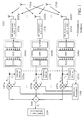
- Fig. 1 shows a block diagram of the receiver 100 in accordance with the preferred embodiment of the underlying invention. It comprises means for performing a channel estimation 105a-c and channel equalization 109. For the RF signals received at each of the antennas 102a-c the same operations are performed. In the following, the operations performed for the signal received at antenna 102b shall representatively be described. At first, the RF signal received at antenna 102b is submitted to a module 103b which performs a downconversion to the baseband, an analog-digital conversion and a removal of the guard interval preceding said signal.
- the OFDM demodulation can be performed by means of a combined module 104b comprising a serial-to-parallel converter (S/P), a digital signal processor performing a Fast Fourier Transform (FFT) and a parallel-to-serial converter (P/S).
- S/P serial-to-parallel converter
- FFT Fast Fourier Transform
- P/S parallel-to-serial converter
- the obtained data vector element x k,i is then weighted by means of a receive (RX) antenna weighting vector element w k,i calculated by means of an adaptive processor 106.
- said receive (RX) antenna weighting vector element w k,i is supplied by the channel estimator 105b having the data vector element x k,i as input signal.
- the receive (RX) antenna weighting vector w k is adaptively updated by means of the adaptive processor 106.
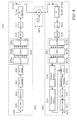
- Fig. 2 exhibits a block diagram of the transmitter 200 comprising means 207 for performing an interference cancellation in accordance with the preferred embodiment of the underlying invention.
- a beamforming algorithm is used for maximizing the energy transmitted in direction of the desired mobile terminal 201a (MT1) and steering nulls in direction of the interfering mobile terminal 201b (MT2).
- MT1 desired mobile terminal
- MT2 interfering mobile terminal
- the operations performed for the signal transmitted from antenna 202b shall representatively be described.
- the OFDM symbol stream 205 to be transmitted from each antenna 202a-c is weighted with the aid of transmit (TX) antenna weighting vectors obtained from module 207.
- the OFDM modulation can be performed by means of a combined module 204b comprising a serial-to-parallel converter (S/P), a digital signal processor performing an Inverse Fast Fourier Transform (IFFT) and a parallel-to-serial converter (P/S).
- a combined module 203b serves to insert a guard interval, to perform a digital-to-analog conversion and a RF upconversion of the signal to be transmitted from antenna 202b.
- Fig. 3 shows a situation 300 in which a first access point 302a (AP1) has to independently estimate interferences coming from an interfering mobile terminal 301b (MT2) in order to steer nulls in direction of said mobile terminal 301b (MT2).
- a second access point 302b (AP2) has to independently estimate interferences coming from an interfering mobile terminal 301a (MT1) in order to steer nulls in direction of said mobile terminal 301a (MT1).
- the access points 302a (AP1) and 302b (AP2) can co-operate by exchanging specific signal bursts comtained in their signal sequences 303a and 303b, respectively.
- Fig. 4 refers to a block diagram 400 for the employed mobile transmission system comprising one mobile transmitter 401 and one mobile receiver 402 for supporting wireless communication over a mobile radio channel by means of a pilot-assisted wireless multi-carrier system considering channel estimation and equalization.
- the input is a binary data stream 404 using any suitable modulation technique.
- a scrambler 405 is used for randomizing the transmitted input data bits 404 in order to minimize interferences.
- the data is then transformed into a multilevel signal to be prepared for an OFDM modulation 409.
- the serial data stream is converted to parallel by means of the serial-parallel converter 409a, the data rate gets reduced by K, where K is the number of parallel subchannels used for the applied OFDM modulation.
- K is the number of parallel subchannels used for the applied OFDM modulation.
- the data symbols are mapped to the subcarriers using an Inverse Fast Fourier Transform (IFFT) performed by a digital signal processor 409b, and reconverted to serial by means of a parallel-serial converter 409c.
- IFFT Inverse Fast Fourier Transform
- a guard interval is inserted with the aid of the guard interval insertion unit 410.
- CP cyclic prefix
- a signal windowing is performed in order to reduce the out-of-band radiation. Therefore, a raised-cosine window function is normally employed.
- the signal is then submitted to a digital-analog converter 411 to produce the analog baseband signal, modulated to the RF carrier wave by means of an RF upconversion unit 412a, amplified, and transmitted over the mobile radio channel 403.
- the mobile radio channel 403 is assumed to be an Additive White Gaussian Noise (AWGN) channel.
- AWGN Additive White Gaussian Noise
- the complementary operations are applied in reverse order.
- the received RF signal is downconverted to the baseband by means of the RF downconverter 414b, and submitted to an analog-digital converter 415.
- the guard interval is removed with the aid of the guard interval removal unit 416, the OFDM demodulation 417 can be performed.
- the data is then transformed into a multilevel signal to be prepared for an OFDM demodulation.
- the serial data stream is converted to parallel by means of the serial-parallel converter 417a, all subcarriers are separated by applying a Fast Fourier Transform (FFT) performed by a digital signal processor 417b, and reconverted to serial by means of a parallel-serial converter 417c.
- FFT Fast Fourier Transform
- the data stream is submitted to a deinterleaver 420 followed by a symbol-to-bit mapper 421, a decoder 422, and a descrambler 423 to obtain the output data bits 424.
- Figs. 5a and 5b exhibit a detailed view of the OFDM modulation 501 performed in the transmitter with multiplexing data symbols and pilot symbols, and the OFDM demodulation 502 performed in the receiver, respectively.
- IFFT Inverse Fast Fourier Transform
- FFT Fast Fourier Transform
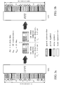
- Fig. 6 shows an example 600 for performing a frequency-domain channel estimation in the receiver 100 by means of preamble symbols.
- an alignment of the subcarrier phase is performed with a predetermined pattern, given by the respective receive (RX) antenna weighting vector element w k,i calculated by means of the adaptive processor 106.
- 601a is an example for an OFDM symbol stream before said alignment of the subcarrier phases;
- 601b shows the OFDM symbol stream after said alignment.
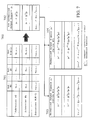
- Fig. 7 presents a scheme 700 for individually applying antenna weighting vectors to all subcarriers. Thereby, pre-equalizing and load swapping techniques can optionally be added.
- 701 shows a matrix scheme comprising transmit (TX) antenna weighting vector elements for each subcarrier k (for 0 ⁇ k ⁇ K-1) and transmit (TX) antenna i (for 0 ⁇ i ⁇ N-1) to maximize the carrier-to-interference ratio (CIR) given by the Rayleigh quotient ⁇ k , or the carrier-to-interference-plus-noise ratio (CINR) given by the Rayleigh quotient ⁇ k ', respectively.
- CIR carrier-to-interference ratio
- CINR carrier-to-interference-plus-noise ratio
- transmit (TX) antenna weighting vector elements are needed to generate the non-normalized scalar output signals y k (for 0 ⁇ k ⁇ K-1) depicted in the vector scheme 702.
- Fig. 8 exhibits a situation 800 in which one access point 802 (AP) can transmit different signals to two different mobile stations 801a (MT1) and 801b (MT2), respectively, at the same frequency and time. Therein, two mutually orthogonal antenna weighting vectors are employed to form null and beam, respectively.
- AP access point 802
- MT1a mobile stations 801a
- MT2b mobile stations 801b
- two mutually orthogonal antenna weighting vectors are employed to form null and beam, respectively.
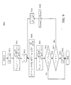
- Fig. 9 shows a a flow chart 900 of an example for choosing the optimum antenna weighting vector according to the preferred embodiment of the underlying invention. It contains the algorithm as described above.
- a calculation 902 of the Rayleigh quotient ⁇ k,before ' : w opt H k A k w opt k w opt H k B k w opt k + ⁇ 2 k ⁇ I representing the carrier-to-interference-plus-noise ratio (CINR) before subtracting the projection of the associated signal channel vector a k onto the orthogonal base u (j) / k of the associated interference channel vector b (j) / k is done.
- a reinitialization 903 of the interferer index (j : 0)
- a calculation 904 of a new antenna weighting vector by means of a first Gram-Schmidt orthogonalization procedure is executed:
- the Rayleigh quotient ⁇ k,after ' : w try H k A k w try k w try H k B k w try k + ⁇ 2 k ⁇ I representing the carrier-to-interference-plus-noise ratio (CINR) after subtracting the projection of the associated signal channel vector a k onto the orthogonal base u (j) / k of the associated interference channel vector b (j) / k is calculated.
- the Rayleigh quotient before performing step 904 is compared with the Rayleigh quotient after having performed step 904.
- the algorithm starts again with step 904.
Abstract
Description
- Sensor array: To receive (and transmit) signals, the sensor array comprises N antenna elements (sensors). The physical arrangement of the array (linear, circular, etc.) is arbitrary, but places fundamental limitations on the capability of the "smart" antenna.
- Beamforming network: The output of each of these N antenna elements is fed into the beamforming network, where the outputs are processed by means of linear time-variant (LTV) filters. These filters determine the directional pattern of the "smart" antenna, that means the relative sensibility of response to signals for a specified frequency from various directions. The outputs of the LTV filters are then summed to form the overall output y(t). The complex weights of the LTV filters are determined by the adaptive processor.
- Adaptive processor: As mentioned above, the adaptive processor determines the complex weights of the beamforming network. The signals and known system features used to compute said weights include the following items: the signals xi(n) (for i = 0,...,N-1) received by the antenna array, the output y(n) of the "smart" antenna, the spatial structure of the antenna array, the temporal structure of the received signal, feedback signals from the mobile stations (MS), and the network topology.
- N
- is the number of antenna elements,
- w ∈ CN
- denotes the complex-valued weighting vector,
- x(n) ∈ CN
- denotes the complex-valued received signal vector,
- y(n) ∈ C
- denotes the complex-valued output signal, and
- 'H'
- denotes the complex conjugate transpose operation (Hermitian transpose).
- A := E{x(n)x(n)H} ∈ CN×N
- is the complex-valued space-time correlation matrix of the time-variant sensor data x(n) ∈ CN from N antenna elements with the discrete time variable n,
- p := E{x(n)·d(n)*} ∈ CN
- is the correlation of the complex-valued sensor data x(n) ∈ CN with the desired signal d(n) ∈ C,
- '*'
- denotes the complex conjugate operation, and
- 'H'
- is the complex conjugate transpose operation (Hermitian transpose).
- µ
- is the constant stepsize, which governs the rate of convergence of said iterative process,
- ε(n) = d(n)-y(n)
- is the error function between the desired signal d(n) and the output y(n), and
- '*'
- denotes the complex conjugate operation.

- xi ∈ CN
- is the i-th received data vector,
- di(n) ∈ C
- is the i-th desired signal at the discrete time n,
- N
- is the number of the antenna elements, and
- wHxi
- denotes the inner product of the vectors w and x i.
- X := [x0, ...., xN-1] ∈ CN×N
- is the received data matrix,
- d(n) := [d0(n), ..., dN-1(n)]T ∈ CN
- denotes the desired signal vector, and
- 'H'
- is the complex conjugate transpose operation (Hermitian transpose).

- A := E{x(n)x(n)H} ∈ CN×N
- is the complex-valued space-time correlation matrix of the time-variant sensor data x(n) ∈ CN from N antenna elements with the discrete time variable n,
- w ∈ CN
- is the desired complex-valued weighting vector,
- wH
- denotes the complex conjugate transpose operation (Hermitian transpose) of w,
- ∥w∥2 := wHw
- denotes the Euclidian length of w,

- 'H'
- denotes the complex conjugate transpose operation (Hermitian transpose), and
- E{.}
- denotes the expected value of its argument.

wherein M is the number of interferers and the complex-valued N×N-dimensional undesired spatial covariance matrix B k is defined as the outer product of the summed interference channel vectors:


- e(0)k
- is the unit vector in the direction of b (0) / k,
- '*'
- denotes the complex conjugate operation,
- 'H'
- denotes the complex conjugate transpose operation, and
- ∥.∥2
- denotes the Euclidian length of a vector argument.


- diversity antennas or adaptive antenna arrays including at least two antenna elements for transmitting and/or receiving modulated radio signals in order to accommodate a large number of mobile terminals within each of said mobile radio cells,
- means for performing an OFDM multi-carrier modulation and/or an OFDM multi-carrier demodulation, respectively, in which each OFDM signal is composed of at least one subcarrier signal each being assigned to a respective transmission channel of said pilot-assisted wireless multi-carrier system, and
- means for individually adjusting the amplitude of at least
one subcarrier signal of an OFDM tranmission signal to be
transmitted for each of said antenna elements in order to
maximize the carrier-to-interference-plus-noise ratio
(CINR) for each subcarrier of said mobile transmission system
given by the Rayleigh quotients for each subcarrier,
which can be calculated by means of the autocorrelation matrix
of the signal channel vectors a k, the interference
channel vectors b k, said antenna weighting vectors w k and
the
noise power σ 2 / k·I of the mobile radio channel.
- FIG. 1
- a block diagram of the receiver comprising means for performing an interference cancellation in accordance with the preferred embodiment of the underlying invention,
- FIG. 2
- a block diagram of the transmitter comprising means for performing an interference cancellation in accordance with the preferred embodiment of the underlying invention, wherein a beamforming algorithm is used for maximizing the energy transmitted in direction of the desired mobile terminal MT1 and steering nulls in direction of the interfering mobile terminal MT2,
- FIG. 3
- a situation in which a first access point AP1 has to independently estimate interferences coming from an interfering mobile terminal MT2 in order to steer nulls in direction of said mobile terminal MT2,
- FIG. 4
- a block diagram for a mobile transmission system supporting wireless communication over a mobile radio channel by means of a pilot-assisted wireless multi-carrier system considering channel estimation and equalization,
- FIG. 5a
- a detailed view of the OFDM modulator,
- FIG. 5b
- a detailed view of the OFDM demodulator
- FIG. 6
- an example for performing a frequency-domain channel estimation in the receiver by means of preamble symbols,
- FIG. 7
- a scheme for individually applying antenna weighting vectors to all subcarriers,
- FIG. 8
- a situation in which one access point AP can transmit different signals to two different mobile stations MT1 and MT2, respectively, at the same frequency and time, and
- FIG. 9
- a flow chart of an example for choosing the optimum antenna weighting vector according to the preferred embodiment of the underlying invention.
| OFDM Transmission Parameter | Prescribed Value |
| sampling period Δt | Δt = 50 ns |
| sampling rate fs | fs = 1 / Δt = 20 MHz |
| symbol duration Ts | Ts = 64·Δt = 3.2 µs |
| guard interval TG (required | optional) | TG = 16·Δt = 0.8 µs | TG = 8·Δt = 0.4 µs |
| symbol interval TMC (required | optional) | TMC = TS + TG = 80·Δt = 4.0 µs | TMC = TS + TG = 72·Δt = 3.6 µs |
| number NSD of subcarriers for data signals | NSD = 48 |
| number NSP of subcarriers for pilot signals | NSP = 4 |
| total number NST of subcarriers | NST ≡ K = NSD + NSP = 52 |
| subchannel spacing Δf between the individual subcarriers | Δf = 1 / TS = 0.3125 MHz |
| subchannel spacing B between the outer subcarriers | B = NST·Δf = 16.25 MHz |
| system bandwidth Bsys | Bsys = 20 MHz |


Claims (25)
- A mobile transmission system comprising at least one mobile transmitter (200) and/or at least one mobile receiver (100) sharing a plurality of mobile radio cells for supporting wireless communication over a mobile radio channel by means of a pilot-assisted wireless multi-carrier system, comprising:characterized bydiversity antennas or adaptive antenna arrays (102a-c, 202a-c) including at least two antenna elements for transmitting and/or receiving modulated radio signals,means for performing an OFDM multi-carrier modulation (204a-c) and/or demodulation (104a-c), in which each OFDM signal is composed of at least one subcarrier signal each being assigned to a respective transmission channel of said pilot-assisted wireless multi-carrier system,means (106, 107a-c, 108) for individually adjusting the amplitude of at least one subcarrier signal of an OFDM tranmission signal to be transmitted for each of said antenna elements (102a-c) in order to maximize the carrier-to-interference-plus-noise ratio (CINR) for each subcarrier of said mobile transmission system given by the Rayleigh quotients for each subcarrier,
means for carrying out a beamforming algorithm, in which antenna weighting vectors are calculated for each subcarrier in such a way that the denominator of the associated Rayleigh quotient becomes a minimum. - A mobile transmission system according to claim 1,
wherein the antenna weighting vectors for each subcarrier are chosen from the orthogonal complement of the space which is spanned by the associated interference channel vectors. - A mobile transmission system according to anyone of the claims 1 or 2,
characterized by
means for performing a first Gram-Schmidt orthogonalization for the interference channel vectors of each subcarrier before calculating the associated antenna weighting vectors for each subcarrier. - A mobile transmission system according to claim 3,
wherein the means for performing said first Gram-Schmidt orthogonalization procedure perform the following steps for each subcarrier:initialization of the antenna weighting vector by setting the antenna weighting vector to the associated signal channel vector,gradual modification of the antenna weighting vector by subtracting the projection of the associated signal channel vector onto the orthogonal base of the associated interference channel vector, in order to obtain an orthogonal set of linearly independent antenna weighting vectors,comparation of the the Rayleigh quotient before and after said subtraction,abandonment of the the subtraction of said projection if the Rayleigh quotient calculated after having performed said subtraction is smaller than before. - A mobile transmission system according to anyone of the claims 3 or 4,
comprising means for the execution of said first Gram-Schmidt orthogonalization procedure for calculating antenna weighting vectors,
wherein a normalized orthogonal base is calculated with the aid of a second Gram-Schmidt orthogonalization procedure in order to improve the efficiency of said first Gram-Schmidt orthogonalization procedure. - A mobile transmission system according to anyone of the claims 1 to 5,
comprising means for normalizing the output power for all subcarriers of the mobile transmitter by dividing it by the inner product of the antenna weighting vector and the signal channel vector in order to obtain an equal subcarrier power in the mobile receiver. - A mobile transmission system according to claim 6,
wherein the transmitted signal is distributed to all antenna elements of the mobile transmitter after said normalization of the output power for all subcarriers of said mobile transmitter. - A mobile transmission system according to anyone of the claims 1 to 7,
wherein the total transmit power from all antenna elements of the mobile transmitter is limited to a predefined upper threshold level. - A mobile transmission system according to anyone of the claims 1 to 7,
wherein a load swapping technique is employed in order to compensate OFDM symbols represented by a reduced bit sequence by changing the modulation scheme of other subcarriers to a more complex scheme which allows to transmit data at a higher data rate. - A mobile transmission system according to claim 9, comprising means for performing a load swapping,
wherein the modulation scheme of subcarriers having a power level higher than a predefined threshold is increased, whereas the modulation scheme of subcarriers having a power level lower than a predefined threshold is decreased, thereby departing from the applied OFDM modulation scheme. - A mobile transmission system according to anyone of the claims 1 to 10,
comprising at least one access point (AP) and at least two mobile terminals (MT),
wherein orthogonalized antenna weighting vectors are applied to provide a duplex operation in said mobile transmission system in order to enable said access points (AP) to independently communicate with two or more of said mobile terminals (MT) at the same frequency and/or time. - A method for operating a mobile transmission system comprising at least one mobile transmitter (200) and/or at least one mobile receiver (100) sharing a plurality of mobile radio cells for supporting wireless communication over a mobile radio channel by means of a pilot-assisted wireless multi-carrier system, comprising:characterized in thatdiversity antennas or adaptive antenna arrays (102a-c, 202a-c) including at least two antenna elements for transmitting and/or receiving modulated radio signals,means for performing an OFDM multi-carrier modulation (204a-c) and/or demodulation (104a-c), in which each OFDM signal is composed of at least one subcarrier signal each being assigned to a respective transmission channel of said pilot-assisted wireless multi-carrier system,means (106, 107a-c, 108) for individually adjusting the amplitude of at least one subcarrier signal of an OFDM tranmission signal to be transmitted for each of said antenna elements (102a-c) in order to maximize the carrier-to-interference-plus-noise ratio (CINR) for each subcarrier of said mobile transmission system given by the Rayleigh quotients for each subcarrier,
antenna weighting vectors are calculated for each subcarrier in such a way that the denominator of the associated Rayleigh quotient becomes a minimum, thereby maximizing the numerator of said Rayleigh quotient. - A method according to claim 12,
wherein the antenna weighting vectors for each subcarrier are chosen from the orthogonal complement of the space which is spanned by the associated interference channel vectors. - A method according to anyone of the claims 12 or 13,
wherein a first Gram-Schmidt orthogonalization is performed for the interference channel vectors of each subcarrier before calculating the associated antenna weighting vectors for each subcarrier. - A method according to claim 14,
wherein for the execution of said first Gram-Schmidt orthogonalization procedure for calculating antenna weighting vectors the following steps are performed:initialization of the antenna weighting vector by setting the antenna weighting vector to the associated signal channel vector,gradual modification of the antenna weighting vector by subtracting the projection of the associated signal channel vector onto the orthogonal base of the associated interference channel vectorin order to obtain an orthogonal set of linearly independent antenna weighting vectors,comparation of the the Rayleigh quotient before and after said subtraction,abandonment of the the subtraction of said projection if the Rayleigh quotient calculated after having performed said subtraction is smaller than before. - A method according to anyone of the claims 14 or 15,
wherein a normalized orthogonal base is calculated with the aid of a second Gram-Schmidt orthogonalization procedure in order to improve the efficiency of said first Gram-Schmidt orthogonalization procedure. - A method according to anyone of the claims 12 to 16,
wherein the output power for all subcarriers of the mobile transmitter is normalized by dividing it by the inner product of the antenna weighting vector and the signal channel vector in order to obtain an equal subcarrier power in the mobile receiver. - A method according to claim 17,
wherein the transmitted signal is distributed to all antenna elements of the mobile transmitter after said normalization of the output power for all subcarriers of said mobile transmitter. - A method according to anyone of the claims 12 to 18,
wherein the total transmit power from all antenna elements of the mobile transmitter is limited to a predefined upper threshold level. - A method according to anyone of the claims 12 to 18,
wherein a load swapping technique is employed in order to compensate OFDM symbols represented by a reduced bit sequence by changing the modulation scheme of other subcarriers to a more complex scheme which allows to transmit data at a higher data rate. - A method according to claim 20,
comprising means for performing a load swapping,
wherein the modulation scheme of subcarriers having a power level higher than a predefined threshold is increased, whereas the modulation scheme of subcarriers having a power level lower than a predefined threshold is decreased, thereby departing from the applied OFDM modulation scheme. - A method according to anyone of the claims 12 to 21,
comprising at least one access point (AP) and at least two mobile terminals (MT),
wherein orthogonalized antenna weighting vectors are applied to provide a duplex operation in said mobile transmission system in order to enable said access points (AP) to independently communicate with two or more of said mobile terminals (MT) at the same frequency and/or time. - A mobile telecommunications device,
characterized in that
it supports a mobile transmission system according to anyone of the claims 1 to 11. - A mobile telecommunications device,
characterized in that
it comprises a mobile transmitter and/or a mobile receiver designed for supporting a method according to anyone of the claims 12 to 22. - A computer program,
which performs, when executed by a processor of a mobile telecommunication device, a method according to anyone of the claims 12 to 22.
Priority Applications (3)
| Application Number | Priority Date | Filing Date | Title |
|---|---|---|---|
| DE60144162T DE60144162D1 (en) | 2001-07-11 | 2001-07-11 | Method for calculating a weight vector for a group antenna |
| EP05025668A EP1667341B1 (en) | 2001-07-11 | 2001-07-11 | Method for calculating a weighting vector for an antenna array |
| EP20010116931 EP1276251B1 (en) | 2001-07-11 | 2001-07-11 | Method for calculating a weighting vector for an antenna array |
Applications Claiming Priority (1)
| Application Number | Priority Date | Filing Date | Title |
|---|---|---|---|
| EP20010116931 EP1276251B1 (en) | 2001-07-11 | 2001-07-11 | Method for calculating a weighting vector for an antenna array |
Related Child Applications (2)
| Application Number | Title | Priority Date | Filing Date |
|---|---|---|---|
| EP05025668A Division EP1667341B1 (en) | 2001-07-11 | 2001-07-11 | Method for calculating a weighting vector for an antenna array |
| EP05025668.4 Division-Into | 2005-11-24 |
Publications (2)
| Publication Number | Publication Date |
|---|---|
| EP1276251A1 true EP1276251A1 (en) | 2003-01-15 |
| EP1276251B1 EP1276251B1 (en) | 2011-05-11 |
Family
ID=8178020
Family Applications (2)
| Application Number | Title | Priority Date | Filing Date |
|---|---|---|---|
| EP20010116931 Expired - Lifetime EP1276251B1 (en) | 2001-07-11 | 2001-07-11 | Method for calculating a weighting vector for an antenna array |
| EP05025668A Expired - Lifetime EP1667341B1 (en) | 2001-07-11 | 2001-07-11 | Method for calculating a weighting vector for an antenna array |
Family Applications After (1)
| Application Number | Title | Priority Date | Filing Date |
|---|---|---|---|
| EP05025668A Expired - Lifetime EP1667341B1 (en) | 2001-07-11 | 2001-07-11 | Method for calculating a weighting vector for an antenna array |
Country Status (2)
| Country | Link |
|---|---|
| EP (2) | EP1276251B1 (en) |
| DE (1) | DE60144162D1 (en) |
Cited By (28)
| Publication number | Priority date | Publication date | Assignee | Title |
|---|---|---|---|---|
| WO2004084420A2 (en) | 2003-03-13 | 2004-09-30 | Motorola, Inc. | Method and apparatus for multi-antenna transmission |
| WO2005024995A3 (en) * | 2003-09-03 | 2005-05-19 | Intel Corp | Communication system and method for channel estimation and beamforming using a multi-element array antenna |
| WO2005055539A1 (en) * | 2003-12-01 | 2005-06-16 | Koninklijke Philips Electronics N.V. | Methods an apparatus of multiple antenna receiver |
| WO2005057808A2 (en) * | 2003-12-03 | 2005-06-23 | Raytheon Company | Beamforming in a gps receiver |
| EP1596548A2 (en) * | 2004-05-13 | 2005-11-16 | NTT DoCoMo, Inc. | Channel estimation device, channel estimation method, and wireless receiver |
| EP1601120A1 (en) * | 2004-05-25 | 2005-11-30 | Micronas GmbH | Method and device for processing received data of a radio interface |
| US7133461B2 (en) * | 2001-12-14 | 2006-11-07 | Motorola, Inc. | Stream transmission method and device |
| KR100651556B1 (en) | 2004-06-30 | 2006-11-29 | 삼성전자주식회사 | Apparatus and method for estimating carrier to interference and noise ratio in communication system |
| USRE40568E1 (en) | 1999-01-08 | 2008-11-11 | Sony Corporation | Synchronization symbol structure using OFDM based transmission method |
| US7480234B1 (en) * | 2003-10-31 | 2009-01-20 | Cisco Technology, Inc. | Initial timing estimation in a wireless network receiver |
| WO2009152852A1 (en) * | 2008-06-18 | 2009-12-23 | Telefonaktiebolaget L M Ericsson (Publ) | Intercell interference reduction |
| US8300712B2 (en) | 2005-09-23 | 2012-10-30 | Koninklijke Philips Electronics N.V. | Equalization for zero prefix OFDM systems |
| CN102857459A (en) * | 2011-06-30 | 2013-01-02 | 中兴通讯股份有限公司 | Method and device for determining demodulation pilot frequencies |
| CN103323861A (en) * | 2013-06-19 | 2013-09-25 | 电子科技大学 | Method for improving steady-state performance of adaptive algorithm |
| EP2673998A1 (en) * | 2011-02-07 | 2013-12-18 | Nokia Corp. | Processing samples of a received rf signal |
| EP2696513A1 (en) * | 2012-08-06 | 2014-02-12 | Telefonaktiebolaget L M Ericsson AB (Publ) | Method and apparatus for adaptive cancellation of external interference |
| CN103987062A (en) * | 2014-04-16 | 2014-08-13 | 华为技术有限公司 | Method and device for eliminating interference of received signals |
| CN105281791A (en) * | 2014-07-24 | 2016-01-27 | 北京信威通信技术股份有限公司 | Interference detection method in OFDM wireless communication system |
| NO340372B1 (en) * | 2004-03-31 | 2017-04-10 | Interdigital Tech Corp | Wireless Transmitter / Receiver Unit (WTRU) attenuation to WTRU interference using multiple antennas or beams |
| US20170163327A1 (en) * | 2015-12-04 | 2017-06-08 | Hon Hai Precision Industry Co., Ltd. | System and method for beamforming wth automatic amplitude and phase error calibration |
| CN108173575A (en) * | 2017-08-28 | 2018-06-15 | 同济大学 | multiple-input and multiple-output relay antenna design method |
| CN109525288A (en) * | 2018-11-28 | 2019-03-26 | 广州市高峰科技有限公司 | For wirelessly communicating the parallel processing architecture of decorrelation operation |
| CN111537947A (en) * | 2020-05-12 | 2020-08-14 | 上海交通大学 | Single radio frequency channel space spectrum estimation direction-finding system and method |
| CN112202693A (en) * | 2020-09-03 | 2021-01-08 | 中国科学院上海微系统与信息技术研究所 | Anti-interference frequency offset estimation method suitable for OFDM system |
| CN112217761A (en) * | 2020-09-21 | 2021-01-12 | 中国科学院上海微系统与信息技术研究所 | Anti-interference frame header demodulation method suitable for OFDM system |
| CN112532560A (en) * | 2020-12-01 | 2021-03-19 | 四川灵通电讯有限公司 | System for adaptively modulating QAM (quadrature amplitude modulation) modulation mode in copper wire transmission and application method |
| CN113466796A (en) * | 2021-08-16 | 2021-10-01 | 电子科技大学 | Radar communication integration method based on coherent phase modulation broadcast mode |
| CN111856402B (en) * | 2020-07-23 | 2023-08-18 | 海尔优家智能科技(北京)有限公司 | Signal processing method and device, storage medium and electronic device |
Families Citing this family (4)
| Publication number | Priority date | Publication date | Assignee | Title |
|---|---|---|---|---|
| IL169417A (en) * | 2005-06-27 | 2011-05-31 | Alvarion Ltd | Method and apparatus for improving signal reception in wireless networks subjected to interference caused by transmissions in neighboring cells |
| CN102916736B (en) * | 2012-10-12 | 2016-01-20 | 广州海格通信集团股份有限公司 | The radio monitoring method and apparatus of wireless communication system |
| KR101934112B1 (en) | 2015-04-02 | 2019-01-02 | 한국전자통신연구원 | Method and apparatus for designing frequency-spatial filter with variable bandwidth |
| CN107026661A (en) * | 2017-03-08 | 2017-08-08 | 恩平市艺星电子有限公司 | A kind of multifrequency carrier wave multilayer diversity wireless transceiver system |
Citations (2)
| Publication number | Priority date | Publication date | Assignee | Title |
|---|---|---|---|---|
| US5982327A (en) * | 1998-01-12 | 1999-11-09 | Motorola, Inc. | Adaptive array method, device, base station and subscriber unit |
| US5999800A (en) * | 1996-04-18 | 1999-12-07 | Korea Telecom Freetel Co., Ltd. | Design technique of an array antenna, and telecommunication system and method utilizing the array antenna |
-
2001
- 2001-07-11 EP EP20010116931 patent/EP1276251B1/en not_active Expired - Lifetime
- 2001-07-11 DE DE60144162T patent/DE60144162D1/en not_active Expired - Lifetime
- 2001-07-11 EP EP05025668A patent/EP1667341B1/en not_active Expired - Lifetime
Patent Citations (2)
| Publication number | Priority date | Publication date | Assignee | Title |
|---|---|---|---|---|
| US5999800A (en) * | 1996-04-18 | 1999-12-07 | Korea Telecom Freetel Co., Ltd. | Design technique of an array antenna, and telecommunication system and method utilizing the array antenna |
| US5982327A (en) * | 1998-01-12 | 1999-11-09 | Motorola, Inc. | Adaptive array method, device, base station and subscriber unit |
Cited By (60)
| Publication number | Priority date | Publication date | Assignee | Title |
|---|---|---|---|---|
| USRE41486E1 (en) | 1999-01-08 | 2010-08-10 | Sony Corporation | Synchronization symbol structure using OFDM based transmission method |
| USRE41431E1 (en) | 1999-01-08 | 2010-07-13 | Sony Corporation | Synchronization symbol structure using OFDM based transmission method |
| USRE40568E1 (en) | 1999-01-08 | 2008-11-11 | Sony Corporation | Synchronization symbol structure using OFDM based transmission method |
| USRE41432E1 (en) | 1999-01-08 | 2010-07-13 | Sony Corporation | Synchronization symbol structure using OFDM based transmission method |
| USRE41470E1 (en) | 1999-01-08 | 2010-08-03 | Sony Corporation | Synchronization symbol structure using OFDM based transmission method |
| USRE41641E1 (en) | 1999-01-08 | 2010-09-07 | Sony Corporation | Synchronization symbol structure using OFDM based transmission method |
| USRE41606E1 (en) | 1999-01-08 | 2010-08-31 | Sony Corporation | Synchronization symbol structure using OFDM based transmission method |
| US7133461B2 (en) * | 2001-12-14 | 2006-11-07 | Motorola, Inc. | Stream transmission method and device |
| EP1609211A2 (en) * | 2003-03-13 | 2005-12-28 | Motorola, Inc. | Method and apparatus for multi-antenna transmission |
| EP1609211A4 (en) * | 2003-03-13 | 2010-06-09 | Motorola Inc | Method and apparatus for multi-antenna transmission |
| US6927728B2 (en) * | 2003-03-13 | 2005-08-09 | Motorola, Inc. | Method and apparatus for multi-antenna transmission |
| WO2004084420A2 (en) | 2003-03-13 | 2004-09-30 | Motorola, Inc. | Method and apparatus for multi-antenna transmission |
| US8165233B2 (en) | 2003-09-03 | 2012-04-24 | Intel Corporation | Multi-element antenna beamforming in a wireless access network |
| EP2262127A3 (en) * | 2003-09-03 | 2012-11-21 | Intel Corporation | Multi-element antenna beamforming in a wireless access network |
| CN102158269B (en) * | 2003-09-03 | 2013-07-17 | 英特尔公司 | Communication system and method for channel estimation and beamforming using a multi-element array antenna |
| US7453946B2 (en) | 2003-09-03 | 2008-11-18 | Intel Corporation | Communication system and method for channel estimation and beamforming using a multi-element array antenna |
| WO2005024995A3 (en) * | 2003-09-03 | 2005-05-19 | Intel Corp | Communication system and method for channel estimation and beamforming using a multi-element array antenna |
| US7480234B1 (en) * | 2003-10-31 | 2009-01-20 | Cisco Technology, Inc. | Initial timing estimation in a wireless network receiver |
| US8159932B1 (en) | 2003-10-31 | 2012-04-17 | Cisco Technology, Inc. | Initial timing estimation in a wireless network receiver |
| WO2005055539A1 (en) * | 2003-12-01 | 2005-06-16 | Koninklijke Philips Electronics N.V. | Methods an apparatus of multiple antenna receiver |
| WO2005057808A3 (en) * | 2003-12-03 | 2005-07-14 | Raytheon Co | Beamforming in a gps receiver |
| US7015858B2 (en) | 2003-12-03 | 2006-03-21 | Raytheon Company | Antijam module |
| WO2005057808A2 (en) * | 2003-12-03 | 2005-06-23 | Raytheon Company | Beamforming in a gps receiver |
| NO340372B1 (en) * | 2004-03-31 | 2017-04-10 | Interdigital Tech Corp | Wireless Transmitter / Receiver Unit (WTRU) attenuation to WTRU interference using multiple antennas or beams |
| US7583739B2 (en) | 2004-05-13 | 2009-09-01 | Ntt Docomo, Inc. | Channel estimation device, channel estimation method, and wireless receiver |
| EP1596548A3 (en) * | 2004-05-13 | 2007-12-05 | NTT DoCoMo, Inc. | Channel estimation device, channel estimation method, and wireless receiver |
| EP1596548A2 (en) * | 2004-05-13 | 2005-11-16 | NTT DoCoMo, Inc. | Channel estimation device, channel estimation method, and wireless receiver |
| EP1601120A1 (en) * | 2004-05-25 | 2005-11-30 | Micronas GmbH | Method and device for processing received data of a radio interface |
| US7778308B2 (en) | 2004-05-25 | 2010-08-17 | Trident Microsystems (Far East) Ltd. | Method and device for processing received data of a radio interface |
| KR100651556B1 (en) | 2004-06-30 | 2006-11-29 | 삼성전자주식회사 | Apparatus and method for estimating carrier to interference and noise ratio in communication system |
| US8300712B2 (en) | 2005-09-23 | 2012-10-30 | Koninklijke Philips Electronics N.V. | Equalization for zero prefix OFDM systems |
| US8838034B2 (en) | 2008-06-18 | 2014-09-16 | Telefonaktiebolaget L M Ericsson (Publ) | Intercell interference reduction |
| WO2009152852A1 (en) * | 2008-06-18 | 2009-12-23 | Telefonaktiebolaget L M Ericsson (Publ) | Intercell interference reduction |
| US9054856B2 (en) | 2011-02-07 | 2015-06-09 | Nokia Technologies Oy | Processing samples of a received RF signal |
| EP2673998A4 (en) * | 2011-02-07 | 2014-05-14 | Nokia Corp | Processing samples of a received rf signal |
| EP2673998A1 (en) * | 2011-02-07 | 2013-12-18 | Nokia Corp. | Processing samples of a received rf signal |
| CN102857459A (en) * | 2011-06-30 | 2013-01-02 | 中兴通讯股份有限公司 | Method and device for determining demodulation pilot frequencies |
| US9148244B2 (en) | 2012-08-06 | 2015-09-29 | Telefonaktiebolaget L M Ericsson (Publ) | Method and apparatus for adaptive cancellation of external interference |
| EP2696513A1 (en) * | 2012-08-06 | 2014-02-12 | Telefonaktiebolaget L M Ericsson AB (Publ) | Method and apparatus for adaptive cancellation of external interference |
| CN103323861A (en) * | 2013-06-19 | 2013-09-25 | 电子科技大学 | Method for improving steady-state performance of adaptive algorithm |
| CN103323861B (en) * | 2013-06-19 | 2015-06-10 | 电子科技大学 | Method for improving steady-state performance of adaptive algorithm |
| CN103987062B (en) * | 2014-04-16 | 2017-06-27 | 华为技术有限公司 | Receive the interference elimination method and device of signal |
| CN103987062A (en) * | 2014-04-16 | 2014-08-13 | 华为技术有限公司 | Method and device for eliminating interference of received signals |
| CN105281791B (en) * | 2014-07-24 | 2017-12-01 | 北京信威通信技术股份有限公司 | A kind of interference detection method in OFDM wireless communication systems |
| CN105281791A (en) * | 2014-07-24 | 2016-01-27 | 北京信威通信技术股份有限公司 | Interference detection method in OFDM wireless communication system |
| CN106877915B (en) * | 2015-12-04 | 2021-03-09 | 鸿海精密工业股份有限公司 | Beam forming method and device for automatically correcting amplitude and phase errors |
| US20170163327A1 (en) * | 2015-12-04 | 2017-06-08 | Hon Hai Precision Industry Co., Ltd. | System and method for beamforming wth automatic amplitude and phase error calibration |
| US9967081B2 (en) * | 2015-12-04 | 2018-05-08 | Hon Hai Precision Industry Co., Ltd. | System and method for beamforming wth automatic amplitude and phase error calibration |
| CN106877915A (en) * | 2015-12-04 | 2017-06-20 | 鸿海精密工业股份有限公司 | The automatic beam forming method and device for correcting amplitude and phase error |
| CN108173575A (en) * | 2017-08-28 | 2018-06-15 | 同济大学 | multiple-input and multiple-output relay antenna design method |
| CN109525288A (en) * | 2018-11-28 | 2019-03-26 | 广州市高峰科技有限公司 | For wirelessly communicating the parallel processing architecture of decorrelation operation |
| CN111537947A (en) * | 2020-05-12 | 2020-08-14 | 上海交通大学 | Single radio frequency channel space spectrum estimation direction-finding system and method |
| CN111856402B (en) * | 2020-07-23 | 2023-08-18 | 海尔优家智能科技(北京)有限公司 | Signal processing method and device, storage medium and electronic device |
| CN112202693B (en) * | 2020-09-03 | 2021-09-28 | 中国科学院上海微系统与信息技术研究所 | Anti-interference frequency offset estimation method suitable for OFDM system |
| CN112202693A (en) * | 2020-09-03 | 2021-01-08 | 中国科学院上海微系统与信息技术研究所 | Anti-interference frequency offset estimation method suitable for OFDM system |
| CN112217761B (en) * | 2020-09-21 | 2021-09-28 | 中国科学院上海微系统与信息技术研究所 | Anti-interference frame header demodulation method suitable for OFDM system |
| CN112217761A (en) * | 2020-09-21 | 2021-01-12 | 中国科学院上海微系统与信息技术研究所 | Anti-interference frame header demodulation method suitable for OFDM system |
| CN112532560A (en) * | 2020-12-01 | 2021-03-19 | 四川灵通电讯有限公司 | System for adaptively modulating QAM (quadrature amplitude modulation) modulation mode in copper wire transmission and application method |
| CN113466796A (en) * | 2021-08-16 | 2021-10-01 | 电子科技大学 | Radar communication integration method based on coherent phase modulation broadcast mode |
| CN113466796B (en) * | 2021-08-16 | 2023-05-26 | 电子科技大学 | Radar communication integrated method based on coherent phase modulation broadcast mode |
Also Published As
| Publication number | Publication date |
|---|---|
| EP1667341B1 (en) | 2011-03-02 |
| EP1276251B1 (en) | 2011-05-11 |
| EP1667341A1 (en) | 2006-06-07 |
| DE60144162D1 (en) | 2011-04-14 |
Similar Documents
| Publication | Publication Date | Title |
|---|---|---|
| EP1276251B1 (en) | Method for calculating a weighting vector for an antenna array | |
| US5982327A (en) | Adaptive array method, device, base station and subscriber unit | |
| US6826240B1 (en) | Method and device for multi-user channel estimation | |
| Vook et al. | Adaptive antennas for OFDM | |
| US6504506B1 (en) | Method and device for fixed in time adaptive antenna combining weights | |
| Budsabathon et al. | Optimum beamforming for pre-FFT OFDM adaptive antenna array | |
| US6362781B1 (en) | Method and device for adaptive antenna combining weights | |
| US7756007B2 (en) | Method to improve channel estimate in broadband SIMO/MIMO cellular radio networks during abrupt interference variations | |
| EP2437448B1 (en) | Method for Processing Received OFDM Data Symbols and OFDM Baseband Receiver | |
| Munster et al. | Co-channel interference suppression assisted adaptive OFDM in interference limited environments | |
| EP1205007B1 (en) | Method of and apparatus for beam reduction and combining in a radio communications system | |
| US20040146024A1 (en) | Method and system for interference reduction in a wireless communication network using a joint detector | |
| CA2553678A1 (en) | Multi-user adaptive array receiver and method | |
| JP2007300606A (en) | Spatial diversity receiver and spatial diversity transmitter | |
| US6445342B1 (en) | Method and device for multi-user frequency-domain channel estimation | |
| EP2575274B1 (en) | Method and receiver for recovering a desired signal transmitted in the presence of one or more interference signals | |
| Choi et al. | Frequency domain pre-equalization with transmit diversity for MISO broadband wireless communications | |
| WO2007093384A1 (en) | Method for optimizing the spacing between receiving antennas of an array usable for counteracting both interference and fading in cellular systems | |
| Bento et al. | Frequency-domain detection without matrix inversions for mmWave communications with correlated massive MIMO channels | |
| KR19990026450A (en) | Structure and Signal Receiving Method of Multicarrier Code Division Multiple Access Receiver Using Antenna Array | |
| Budsabathon et al. | On a novel pre-FFT OFDM adaptive antenna array for delayed signal suppression | |
| Bahri et al. | Performance of adaptive beamforming algorithm for LMS-MCCDMA MIMO smart antennas. | |
| Kadhim | PHY01 Design and Implementation of Adaptive Antenna System in Physical Layer CDMA Transceivers Based Multiwavelet Signals | |
| Kadhim | Implementation of Adaptive Antenna System in CDMA Transceivers Based Multiwavelet Signals | |
| Kuzminskiy et al. | Data Regularized Signal Recovery and Interference Rejection in High Mobility Scenarios |
Legal Events
| Date | Code | Title | Description |
|---|---|---|---|
| PUAI | Public reference made under article 153(3) epc to a published international application that has entered the european phase |
Free format text: ORIGINAL CODE: 0009012 |
|
| AK | Designated contracting states |
Kind code of ref document: A1 Designated state(s): AT BE CH CY DE DK ES FI FR GB GR IE IT LI LU MC NL PT SE TR |
|
| AX | Request for extension of the european patent |
Free format text: AL;LT;LV;MK;RO;SI |
|
| 17P | Request for examination filed |
Effective date: 20030411 |
|
| AKX | Designation fees paid |
Designated state(s): DE FR GB |
|
| 17Q | First examination report despatched |
Effective date: 20050523 |
|
| RAP1 | Party data changed (applicant data changed or rights of an application transferred) |
Owner name: SONY DEUTSCHLAND GMBH |
|
| RAP1 | Party data changed (applicant data changed or rights of an application transferred) |
Owner name: SONY DEUTSCHLAND GMBH |
|
| RAP1 | Party data changed (applicant data changed or rights of an application transferred) |
Owner name: SONY DEUTSCHLAND GMBH |
|
| GRAJ | Information related to disapproval of communication of intention to grant by the applicant or resumption of examination proceedings by the epo deleted |
Free format text: ORIGINAL CODE: EPIDOSDIGR1 |
|
| GRAP | Despatch of communication of intention to grant a patent |
Free format text: ORIGINAL CODE: EPIDOSNIGR1 |
|
| GRAP | Despatch of communication of intention to grant a patent |
Free format text: ORIGINAL CODE: EPIDOSNIGR1 |
|
| GRAS | Grant fee paid |
Free format text: ORIGINAL CODE: EPIDOSNIGR3 |
|
| GRAA | (expected) grant |
Free format text: ORIGINAL CODE: 0009210 |
|
| AK | Designated contracting states |
Kind code of ref document: B1 Designated state(s): DE FR GB |
|
| REG | Reference to a national code |
Ref country code: GB Ref legal event code: FG4D |
|
| REG | Reference to a national code |
Ref country code: DE Ref legal event code: R096 Ref document number: 60144607 Country of ref document: DE Effective date: 20110622 |
|
| PLBE | No opposition filed within time limit |
Free format text: ORIGINAL CODE: 0009261 |
|
| STAA | Information on the status of an ep patent application or granted ep patent |
Free format text: STATUS: NO OPPOSITION FILED WITHIN TIME LIMIT |
|
| 26N | No opposition filed |
Effective date: 20120214 |
|
| REG | Reference to a national code |
Ref country code: DE Ref legal event code: R097 Ref document number: 60144607 Country of ref document: DE Effective date: 20120214 |
|
| PGFP | Annual fee paid to national office [announced via postgrant information from national office to epo] |
Ref country code: FR Payment date: 20120806 Year of fee payment: 12 |
|
| REG | Reference to a national code |
Ref country code: FR Ref legal event code: ST Effective date: 20140331 |
|
| PG25 | Lapsed in a contracting state [announced via postgrant information from national office to epo] |
Ref country code: FR Free format text: LAPSE BECAUSE OF NON-PAYMENT OF DUE FEES Effective date: 20130731 |
|
| PGFP | Annual fee paid to national office [announced via postgrant information from national office to epo] |
Ref country code: GB Payment date: 20140721 Year of fee payment: 14 |
|
| GBPC | Gb: european patent ceased through non-payment of renewal fee |
Effective date: 20150711 |
|
| PG25 | Lapsed in a contracting state [announced via postgrant information from national office to epo] |
Ref country code: GB Free format text: LAPSE BECAUSE OF NON-PAYMENT OF DUE FEES Effective date: 20150711 |
|
| REG | Reference to a national code |
Ref country code: DE Ref legal event code: R084 Ref document number: 60144607 Country of ref document: DE |
|
| PGFP | Annual fee paid to national office [announced via postgrant information from national office to epo] |
Ref country code: DE Payment date: 20200721 Year of fee payment: 20 |
|
| REG | Reference to a national code |
Ref country code: DE Ref legal event code: R071 Ref document number: 60144607 Country of ref document: DE |