EP1275964A1 - Measuring method for immunochromatographic test strip - Google Patents
Measuring method for immunochromatographic test strip Download PDFInfo
- Publication number
- EP1275964A1 EP1275964A1 EP01919809A EP01919809A EP1275964A1 EP 1275964 A1 EP1275964 A1 EP 1275964A1 EP 01919809 A EP01919809 A EP 01919809A EP 01919809 A EP01919809 A EP 01919809A EP 1275964 A1 EP1275964 A1 EP 1275964A1
- Authority
- EP
- European Patent Office
- Prior art keywords
- light
- immunochromatography test
- test piece
- optical system
- cylindrical lens
- Prior art date
- Legal status (The legal status is an assumption and is not a legal conclusion. Google has not performed a legal analysis and makes no representation as to the accuracy of the status listed.)
- Withdrawn
Links
Images


Classifications
-
- G—PHYSICS
- G01—MEASURING; TESTING
- G01N—INVESTIGATING OR ANALYSING MATERIALS BY DETERMINING THEIR CHEMICAL OR PHYSICAL PROPERTIES
- G01N21/00—Investigating or analysing materials by the use of optical means, i.e. using sub-millimetre waves, infrared, visible or ultraviolet light
- G01N21/84—Systems specially adapted for particular applications
- G01N21/8483—Investigating reagent band
-
- G—PHYSICS
- G01—MEASURING; TESTING
- G01N—INVESTIGATING OR ANALYSING MATERIALS BY DETERMINING THEIR CHEMICAL OR PHYSICAL PROPERTIES
- G01N21/00—Investigating or analysing materials by the use of optical means, i.e. using sub-millimetre waves, infrared, visible or ultraviolet light
- G01N21/75—Systems in which material is subjected to a chemical reaction, the progress or the result of the reaction being investigated
- G01N21/77—Systems in which material is subjected to a chemical reaction, the progress or the result of the reaction being investigated by observing the effect on a chemical indicator
- G01N21/78—Systems in which material is subjected to a chemical reaction, the progress or the result of the reaction being investigated by observing the effect on a chemical indicator producing a change of colour
-
- G—PHYSICS
- G01—MEASURING; TESTING
- G01N—INVESTIGATING OR ANALYSING MATERIALS BY DETERMINING THEIR CHEMICAL OR PHYSICAL PROPERTIES
- G01N33/00—Investigating or analysing materials by specific methods not covered by groups G01N1/00 - G01N31/00
- G01N33/48—Biological material, e.g. blood, urine; Haemocytometers
- G01N33/50—Chemical analysis of biological material, e.g. blood, urine; Testing involving biospecific ligand binding methods; Immunological testing
- G01N33/53—Immunoassay; Biospecific binding assay; Materials therefor
- G01N33/558—Immunoassay; Biospecific binding assay; Materials therefor using diffusion or migration of antigen or antibody
Definitions
- the present invention relates to a device for measuring immunochromatography test pieces.
- antibodies which provoke a antigen or antibody reaction with antigens (or antibodies) in a subject (sample) are previously coated in strips onto prescribed positions of an immunochromatography test piece.
- the antigens (or antibodies) in the subject are dissolved out using a developer solution, and are caused to impregnate into the immunochromatography test piece, whereupon the antigens (or antibodies) in the subject are trapped by an antigen or antibody reaction in the region of the antigens (or antibodies) coated onto the immunochromatography test piece.
- the quantity trapped is the total amount of that antigen (or antibody) in the subject
- Immunochromatography analysis can be used for measuring extremely small quantities, compared to standard colorimetric methods.
- Japanese Patent Laid-open No. H7-5110 discloses a measuring device for measuring the concentration of a specific material in a subject from an immunochromatography test piece after development and dying of the subject.
- light from an LED is irradiated onto an immunochromatography test piece, the light reflected from the immunochromatography test piece is detected by a CCD color image sensor, and the degree of coloration is identified.
- the portion which is colored by the antigen or antibody reaction extends in a direction which intersects with the path of movement of the subject, and cases are observed wherein uneven coloring occurs in the direction in which the colored portion extends. If uneven coloring occurs in the colored portion in this way, then it becomes difficult to measure the degree of coloring with good accuracy.
- the present invention was devised with the foregoing in view, an object thereof being to provide a measuring device for immunochromatography test pieces which is capable of measuring the degree of coloring of immunochromatography test pieces to a high level of accuracy.
- the measuring device for immunochromatography test pieces is a measuring device for immunochromatography test pieces, comprising an irradiation optical system for irradiating measurement light onto immunochromatography test pieces; and a detection optical system for detecting light from the immunochromatography test pieces due to the measurement light; characterized in that the detection optical system comprises a cylindrical lens and an imaging element; and the cylindrical lens is disposed in such a manner that the direction of the generating line thereof intersects with the direction of travel of antigens or antibodies in the immunochromatography test piece, and creates an image of a pattern formed in a direction intersecting with the direction of travel of the antigens or antibodies, on the imaging element, due to the irradiation of the measurement light from the irradiation optical system.
- the detection optical system has a cylindrical lens and an imaging element, and in particular, the cylindrical lens is disposed in such a manner that the direction of the generating line thereof intersects with the direction of travel of antigens or antibodies in the immunochromatography test piece, and creates an image of a pattern formed in a direction intersecting with the direction of travel of the antigens or antibodies, on the imaging element, due to the irradiation of the measurement light from the irradiation optical system. Therefore, light that is parallel to the direction of travel of the antigens or antibodies in the immunochromatography test piece is formed as an image on the imaging element, and light that is orthogonal to the direction of travel of the antigens or antibodies in the immunochromatography test piece is defocused and equalized.
- the measuring device for immunochromatography test pieces according to the present invention may be further characterized in that a member formed with a slit extending in the direction of the generating line of the cylindrical lens is further provided between the immunochromatography test piece and the cylindrical lens.
- the measuring device for immunochromatography test pieces may be further characterized in that the imaging element is a linear image sensor wherein a plurality of light-receiving elements are arrayed in a direction approximately orthogonal to the direction of the generating line of the cylindrical lens.
- the measuring device for immunochromatography test pieces according to the present invention may be further characterized in that the irradiation optical system and the detection optical system are disposed in such a manner that the imaging element receives the transmitted light of the measurement light irradiated onto the immunochromatography test piece; and the light absorption of the color pattern is measured on the basis of the transmitted light received by the imaging element.
- the degree of coloration of the immunochromatography test piece can be measured simply and very accurately. Consequently, the total amount of antigens or antibodies can be measured precisely.
- the measuring device for immunochromatography test pieces according to the present invention may be further characterized in that the irradiation optical system and the detection optical system are disposed in such a manner that the imaging element receives the reflected light of the measurement light irradiated onto the immunochromatography test piece; and the reflectivity of the color pattern is measured on the basis of the reflected light received by the imaging element.
- the degree of coloration of the immunochromatography test piece can be measured simply and very accurately. Consequently, the total amount of antigens or antibodies can be measured precisely.
- a measuring device for immunochromatography test pieces relating to an embodiment of the present invention is now described with reference to the drawings.
- similar elements or elements having similar functions are similarly labelled, and duplicated description thereof is omitted.
- a measuring device 1 for immunochromatography test pieces relating to a first embodiment is described with reference to Fig. 1.
- the measuring device 1 comprises an irradiating optical system 20 for irradiating measurement light onto an immunochromatography test piece 10, and a detection optical system 30 for detecting light from an immunochromatography test piece 10 by irradiation of the measurement light.
- the irradiation optical system 20 comprises a light-emitting element 21 and a mixing rod 22.
- the detection optical system 30 comprises an aperture 31, a cylindrical lens 33 forming an imaging lens, and a CCD image sensor 36 forming an imaging element.
- the immunochromatography test piece 10 has a long rectangular shape and is made from a material such as a nitrocellulose membrane, or filter paper, or the like. This immunochromatography test piece 10 is held inside a casing 11 having a long rectangular shape in plan view, and a subject application window 12, observation window 13 and control window 14 are provided extending in the direction of the longer side in the casing 11.
- the immunochromatography test piece 10 comprises a subject application section 15 provided in a position corresponding to the subject application window 12, and detecting sections 16, 17 provided in positions corresponding to the observation window 13 and control window 14.
- the detecting section 16 has a line shape (or band shape) formed by coating respective antigens (or antibodies) which react with antigens (or antibodies) in the subject, and causing same to solidify.
- the casing 11 which holds the immunochromatography test piece 10 is held by holding means (not illustrated).
- the observation window 13 has a size of 4 mm x 8 mm, for example.
- the subject is applied dropwise via the subject application window 12 onto the subject application section 15 of the immunochromatography test piece 10.
- the antigens (or antibodies) in the subject couple with the indicator dye and the indicator dye coupled with the antigens (or antibodies) in the subject, as well as unreacted indicator dye, travel in the longitudinal direction of the immunochromatography test piece 10. Supposing that the subject contains antigens, then it is assumed that the antigens will undergo an antigen/antibody reaction with the respective detecting sections.
- the antigens in the subject and the antigens fixed to the detecting section 16 react specifically and a line-shaped pattern 18 colored by the indicator dye is formed in the detecting section 16 where reaction has taken place.
- This colored line-shaped pattern 18 is formed extending in a direction intersecting (for example, orthogonally) with the direction of travel of the antigens (or antibodies) of the subject in the immunochromatography test piece 10, and it can be observed by means of the observation window 13.
- the light-emitting element 21 comprises a plurality of LEDs having different light emission wavelengths, in the present embodiment, a blue LED 21B and a red LED 21R. If the line-shaped pattern 18 formed by the antigen/antibody reaction is colored red, then the blue LED 21B is caused to emit light. If the line-shaped pattern 18 formed by the antigen/antibody reaction is colored blue, then the red LED 21R is caused to emit light.
- the mixing rod 22 is a square-shaped (or circular-shaped) rod made from transparent acrylic resin for mixing the light output by the light-emitting element 21 (blue LED 21B or red LED 21R), and it has a light input face and a light output face at the respective ends thereof.
- the aforementioned light-emitting element 21 is positioned on the light input face side of the mixing rod 22.
- An immunochromatography test piece 10 (casing 11) is positioned on the light output face side of the mixing rod 22. More specifically, the immunochromatography test piece 10 (casing 11) is positioned opposing the light output face of the mixing rod 22 in such a manner that the observation window 13 of the casing 11 coincides with the light output face of the mixing rod 22.
- the light output face of the mixing rod 22 has a size of 8 mm x 14 mm, and the surface area of the light output face of this mixing rod 22 is set to a larger area than the surface area of the opening in the observation window 13 of the casing 11.
- Diffusion plates 23, 24 forming diffusing means are provided at the light input face and light output face of the mixing rod 22, in a state of contact with the light input face and light output face of the mixing rod 22.
- These diffusing plates 23, 24 are made from opaque acrylic resin. Instead of providing diffusing plates 23, 24, it is also possible to form the actual light input face and light output face of the mixing rod 22 into ground glass surfaces in order to provide diffusing means.
- the light output from the light-emitting element 21 (blue LED 21B or red LED 21R) is diffused by the diffusing plate 23 and then enters into the mixing rod 22 via the light input face of the mixing rod 22.
- the light that has entered the mixing rod 22 is mixed by being fully reflected at the side faces of the mixing rod 22 whilst it is propagated therein, and this mixed light arrives at the light output face of the mixing rod 22.
- the light arriving at the light output face of the mixing rod 22 is diffused by the diffusing plate 24, and is then irradiated as measurement light from the rear face of the observation window 13 of the casing 11 in the direction of the immunochromatography test piece 10 (observation window 13 of the casing 11).
- the cylindrical lens 33 is positioned in such a manner that the direction of the generating line of the curved face of the cylindrical lens 33 intersects (for example, orthogonally) with the direction of travel of the antigens (or antibodies) of the subject in the immunochromatography test piece 10, in other words, in such a manner that it is facing in the direction of extension of the line-shaped pattern 18 formed by coloration of the immunochromatography test piece 10.
- the cylindrical lens 33 forms an image of the line-shaped pattern 18 formed in the immunochromatography test piece 10, by means of the input transmitted light from the immunochromatography test piece 10 (casing 11).
- the aperture 31 is positioned on the light input face side of the cylindrical lens 33.
- a long rectangular-shaped slit 32 extending in the direction of the generating line of the curved face of the cylindrical lens 33 is formed in the aperture 31.
- the slit 32 in the aperture 31 restricts the transmitted light which passes through the immunochromatography test piece 10 (casing 11) upon irradiation of measurement light and is emitted via the observation window 13.
- An aperture 34 for restricting light other the light from the observation window 13 from being input to the cylindrical lens 33 is provided on the light output face of the immunochromatography test piece 10 (casing 11).
- a hole section 35 for passing the transmitted light from the immunochromatography test piece 10 (casing 11) is provided in the aperture 34.
- the CCD image sensor 36 has a light receiving face 37, which is situated at the position where an image of the transmitted light from the immunochromatography test piece 10 (casing 11) is formed by the cylindrical lens 33.
- Light-receiving elements are provided in a one-dimensional or two-dimensional array on the light-receiving face 37.
- the CCD image sensor 36 detects the transmitted light from the immunochromatography test piece 10 by capturing the image formed by the cylindrical lens 33 on the light receiving face 37.
- the concentration of the subject is determined as described below, on the basis of the output signal from the CCD image sensor 36.
- a light absorption profile of the transmitted light of the immunochromatography test piece 10 is created as illustrated in Fig. 2, on the basis of the output signal intensity from the CCD image sensor 36 and the position of the light-receiving element (channel) of the CCD image sensor 36.
- the light absorption ABS is calculated by means of the following equation (1), taking T o as the output signal intensity at a position in the created absorption profile corresponding to a portion of the immunochromatography test piece 10 that is not colored, and taking T i as the output light intensity at a position corresponding to a colored region thereof (line-shaped pattern 18).
- T o the output signal intensity at a position in the created absorption profile corresponding to a portion of the immunochromatography test piece 10 that is not colored
- T i the output light intensity at a position corresponding to a colored region thereof
- the total quantity (concentration) of antibodies or antigens contained in the subjected is derived from the light absorption ABS, by referring to a previously created quantity characteristics graph.
- an irradiation optical system 20 and a detection optical system 30 are provided in the measuring device 1.
- the irradiation optical system 20 comprises a light-emitting element 21 (blue LED 21B or red LED 21R), and a mixing rod 22, and the light emitted from the mixing rod 22 is irradiated as measurement light onto the immunochromatography test piece 10 (casing 11).
- the detection optical system 30 comprises a cylindrical lens 33 and CCD image sensor 36, and detects transmitted light from the immunochromatography test piece 10 (casing 11) by means of the CCD image sensor 36.
- the light output by the light-emitting elements 21 is mixed by the mixing rod 22 before being irradiated onto the immunochromatography test piece 10 (casing 11), attenuation of the light from the light-emitting elements 21 is suppressed, and the amount of light irradiated onto the immunochromatography test piece 10 is increased. Consequently, the CCD image sensor 36 is able reliably to detect a line-shaped pattern 18 formed by coloration of the immunochromatography test piece 10. Moreover, since light-emitting elements 21 (a blue LED 21B and a red LED 21R) are used, it is possible to suppress increase in the size of the measuring device 1.
- the measuring device 1 since diffusing plates 23, 24 are provided at the light input face and light output face of the mixing rod 22, the light irradiated onto the immunochromatography test piece 10 (casing 11) is approximately equalized. Thereby, it is possible to perform detection of the line-shaped pattern 18 in the immunochromatography test piece 10 by means of the CCD image sensor 36 with even greater reliability.
- the measuring device 1 since the surface area of the light output face of the mixing rod 22 is greater than the surface area of the observation window 13 of the casing 11, the light irradiated onto a position corresponding to the observation window 13 of the immunochromatography test piece 10 will be further equalized. Thereby, the detection of the line-shaped pattern 18 in the immunochromatography test piece 10 by means of the CCD image sensor 36 can be performed with even greater reliability.
- the measuring device 1 has a cylindrical lens 33 forming an imaging lens, this cylindrical lens 33 being provided in such a manner that the direction of the generating line of the curved face thereof intersects with the direction of travel of the antigens or antibodies in the immunochromatography test piece 10, and due to irradiation of measurement light, an image of the line-shaped pattern 18 formed in a direction intersecting with the direction of travel of the antigens or antibodies is formed on the CCD image sensor 36.
- light which is parallel to the direction of travel of the antigens or antibodies in the immunochromatography test piece 10 is formed as an image on the CCD image sensor 36, and light which is orthogonal to the direction of travel of the antigens or antibodies in the immunochromatography test piece 10 is defocused and equalized.
- the uneven coloration is equalized optically by the cylindrical lens 33, and a pattern wherein the uneven discoloration is equalized optically is formed as an image on the CCD image sensor 36.
- the degree of coloration of the line-shaped pattern 18 formed in the immunochromatography test piece 10 can be measured with good accuracy.
- the aperture 31 formed with a long rectangular-shaped slit 32 extending in the direction of the generating line of the curved face of the cylindrical lens 33 is disposed on the light input face side of the cylindrical lens 33, it is possible to focus an image having little aberration on the CCD image sensor 36.
- the irradiation optical system 20 and detection optical system 30 in the measuring device 1 are positioned in such a manner that the CCD image sensor 36 receives the transmitted light of the measurement light irradiated onto the immunochromatography test piece 10, and the light absorption of the line-shaped pattern 18 formed by coloration is measured on the basis of the transmitted light received by the CCD image sensor 36.
- the degree of coloration of the line-shaped pattern 18 formed in the immunochromatography test piece 10 can be measured simply and very accurately, and the total amount (concentration) of antigens or antibodies contained in the subject can be measured precisely.
- the measuring device 101 for an immunochromatography test piece relating to a second embodiment differs from the measuring device 1 relating to the first embodiment in that the light path is constituted in a bent fashion by using mirrors.
- the measuring device 101 comprises a case 102, and a lid (not illustrated) which fits onto the case 102.
- a chassis 104 is fitted inside the case 102 in order to position an irradiation optical system 20, a detection optical system 30, and a control circuit 103 for controlling the operation of the measuring device 101 by performing various calculation processes.
- the light-emitting elements 21 (blue LED 21B or red LED 21R) are fixed to an installation plate 105, and this installation plate 105 is attached to the chassis 104 via a bracket 106.
- a mixing rod 22 is situated inside a rod case 107, in a state whereby the light input face and light output face of the mixing rod 22 contact diffusion plates 23, 24.
- the position of the mixing rod 22 in the direction of the light guide is limited by means of a restricting section 108 formed integrally with the rod case 107 confronting the diffusion plate 24, and a rod pressing plate 109 combined with the rod case 107 confronting the diffusion plate 23.
- a plurality of rod holders 110 are installed on the side face of the mixing rod 22, at prescribed intervals in the light guide direction of the mixing rod 22.
- the position of the mixing rod 22 in the direction orthogonal to the light guide direction thereof is limited by means of these rod holders 110 confronting the side walls of the rod case 107.
- test piece holder 111 constituted so that an immunochromatography test piece 10 (casing 11) can be inserted therein, is provided on the upper face of the restricting section 108 (rear side of the face confronting the diffusion plate 24).
- This test piece holder 111 functions as holding means for holding the immunochromatography test piece 10 (casing 11).
- the test piece holder 111 is constituted in such a manner that, the casing 11 makes contact with the aperture 34, when it is inserted inside the test piece holder 111 and positioned in a test piece installation section 112 formed integrally with the aperture 34.
- the test piece holder 111 is installed on the chassis 104 in a state where the restricting section 108 and test piece installation section 112 are in mutual contact.
- the insertion position of the immunochromatography test piece 10 (casing 11) in the longitudinal direction is restricted by means of a restricting section 113 formed integrally with the rod case 107 (restricting section 108) making contact with the end of the casing 11 in the longitudinal direction thereof.
- a hole section 35 for passing transmitted light from the immunochromatography test piece 10 (casing 11) is provided in the aperture 34.
- the hole section 35 of the aperture 34 has a size of 5 mm ⁇ 8 mm.
- a hole section 214 for irradiating light from the diffusion plate 24 onto the immunochromatography test piece 10 (casing 11) is provided on the test piece installation section 112 of the test piece holder 111.
- the hole section 114 of the test piece installation section 112 has a size of 8 mm ⁇ 14 mm.
- the light output face of the mixing rod 22 also has a size of 8 mm ⁇ 14 mm.
- the observation window has a size of 4 mm ⁇ 8 mm.
- a mirror 115 is provided on top of the test piece holder 111.
- This mirror 115 is installed on the chassis 104 via a mirror holder 116.
- the light reflected by the mirror 115 is input to the cylindrical lens 33.
- the light path is bent in the measuring device 101 by means of this mirror 115, and as illustrated in Fig. 3, the irradiation optical system 20 and the detection optical system 30 are located in an inverse L shape.
- the control circuit 103 is installed on the chassis 104 in a position to the inner side of the irradiation optical system 20 and detection optical system 30 provided in an inverse L shape.
- the cylindrical lens 33 is positioned in such a manner that the direction of the generating line of the curved face of the cylindrical lens 33 intersects (orthogonally, for example,) with the direction of travel of the antigens (or antibodies) of the subject in the immunochromatography test piece 10, in other words, in such a manner that it faces in the direction of extension of the line-shaped pattern 18 formed by coloration in the immunochromatography test piece 10.
- a lens mask 117 forming an aperture is positioned on the light input side of the cylindrical lens 33. As shown in Fig. 7, a long rectangular slit 32 extending in the direction of the generating line of the curved face of the cylindrical lens 33 is formed in the lens mask 117. The size of this slit 32 is set to 4 mm ⁇ 8 mm.
- the cylindrical lens 33 and lens mask 117 are held on either side by a lens holder 118 and pressing ring 119, by means of the lens holder 118 and pressing ring 119 being screw fitted together.
- the lens holder 118 is fixed in a state where it is inserted into a hole section of a lens installation tube 120.
- the lens installation tube 120 with the lens holder 118 fixed thereto is installed on the chassis 104.
- the linear array CCD image sensor 136 has a light receiving face 137 extending in a one-dimensional direction, as illustrated in Fig. 8.
- the linear array CCD image sensor 136 is disposed in such a manner that the light receiving face 137 thereof is positioned at the point where the transmitted light from the immunochromatography test piece 10 (casing 11) is formed into an image by the cylindrical lens 33.
- a plurality of light-receiving elements are disposed in a one-dimensional fashion on the light receiving face 137 of the linear array CCD image sensor 136.
- the linear array CCD image sensor 136 is fixed to a sensor holder 139 by means of a substrate 138, and this sensor holder 139 is attached to the chassis 104 via a sensor installation tube 140.
- the direction of extension of the light receiving face 137 of the linear array CCD image sensor 136 is a direction which intersects with the direction of the generating line of the curved face of the cylindrical lens 33, when the linear array CCD image sensor 136 is installed in the chassis 104.
- a baffle plate 141 for eliminating stray light is provided between the cylindrical lens 33 and the linear array CCD image sensor 136. Hole sections 142, 143 for transmitting light exiting from the cylindrical lens 33 are formed in this baffle plate 141.
- the baffle plate 141 is installed on the chassis 104.
- the detection optical system from the aperture 34 to the linear array CCD image sensor 136 is covered by a light shielding tube 150 in order to optically shield this detection optical system.
- the light shielding tube 150 is installed on the chassis 104.
- the measuring device 101 having the foregoing composition provides the same action and beneficial effects as the measuring device 1 relating to the first embodiment and is able reliably to detect a line-shaped pattern 18 formed by coloration of an immunochromatography test piece 10, by means of the linear array CCD image sensor 136. Moreover, since light-emitting elements 21 (blue LED 21B or red LED 21R) are used as light sources, it is possible to prevent increase in the size of the measuring device 101.
- the measuring device 101 has a cylindrical lens 33 as an imaging lens, and this cylindrical lens 33 is disposed so that the direction of the generating line of the curved face thereof intersects with the direction of travel of the antigens or antibodies in the immunochromatography test piece 10, and it forms an image of the line-shaped pattern 18 formed in a direction intersecting with the direction of travel of the antigens or antibodies, on the linear array CCD image sensor 136, due to irradiation of measurement light.
- a lens mask 117 formed with a long rectangular slit 32 extending in the direction of the generating line of the curved face of the cylindrical lens 33 is provided at the light input face of the cylindrical lens 33, it is possible to form an image having little aberration on the linear array CCD image sensor 136.
- a measuring device 101 since a linear array CCD image sensor 136 is used as an imaging element, a measuring device 101 having an inexpensive and compact composition can be achieved. As described above, since any unevenness in coloration is optically equalized by the cylindrical lens 33, it is possible to measure the degree of coloration of the line-shaped pattern 18 formed in the immunochromatography test piece 10 with a high level of accuracy, even if a linear array CCD image sensor 136 is used as an imaging element.
- the measuring device 201 for immunochromatography test pieces relating to a third embodiment differs from the measuring devices 1, 101 relating to the first embodiment and second embodiment in that the transmitted light and the reflected light of the measurement light irradiated onto an immunochromatography test piece are detected by the imaging element.
- the irradiation optical system 20 comprises a first irradiation optical system 20A for irradiating measurement light from the rear side of an immunochromatography test piece 10 (casing 11), and a second irradiation optical system 20B for irradiating measurement light from the front side of an immunochromatography test piece 10 (casing 11).
- the immunochromatography test piece 10 (casing 11) is held in a test piece holder 111 forming holding means.
- the first irradiation optical system 20A comprises, as a light-emitting element, a red LED 21R (or blue LED 21B), and a first mixing rod 22A.
- the light input face and light output face of a first mixing rod 22A are processed to ground glass faces.
- Light output from the red LED 21R (or blue LED 21B) is diffused by the ground glass face of the light input face of the first mixing rod 22A, and enters into the first mixing rod 22A.
- the light that has entered into the first mixing rod 22A is mixed by total reflection at the side faces of the first mixing rod 22A as it propagates therein, and it is diffused and output from the light output face of the first mixing rod 22A.
- the light exiting the first mixing rod 22A is irradiated onto the immunochromatography test piece 10 (observation window 13 of casing 11) as measurement light, from the rear side of the observation window 13 of the casing 11.
- the second irradiation optical system 20B comprises a blue LED 21B (or red LED 21R) as a light-emitting element, a second mixing rod 22B, and a condensing lens 202.
- the light input face and light output face of the second mixing rod 22B are processed to ground glass faces, similarly to the first mixing rod 22A.
- Light emitted by the blue LED 21B (or red LED 21R) is diffused by the ground glass face of the light input face of the first mixing rod 22B, and enters into the second mixing rod 22B.
- the light that has entered into the second mixing rod 22B is mixed by total reflection at the side faces of the second mixing rod 22B as it propagates therein, and it is diffused and output from the light output face of the second mixing rod 22B.
- the light exiting the second mixing rod 22B is condensed by the condensing lens 202, and is then irradiated onto the immunochromatography test piece 10 (observation window 13 of casing 11) as measurement light, via the observation window 13 of the casing 11.
- the measurement light irradiated from the first irradiation optical system 20A is received and detected as transmitted light from the immunochromatography test piece 10 (casing 11) by the linear array CCD image sensor 136. Furthermore, the measurement light irradiated from the second irradiation optical system 20B is received as detected as reflected light from the immunochromatography test piece 10 (casing 11) by the linear array CCD image sensor 136.
- a cylindrical lens 33 is positioned in such a manner that the direction of the generating line of the curved face of the cylindrical lens 33 intersects (orthogonally, for example,) with the direction of travel of the antigens (or antibodies) of the subject in the immunochromatography test piece 10, in other words, in such a manner that it faces in the direction of extension of the line-shaped pattern 18 formed by coloration in the immunochromatography test piece 10.
- a lens mask 117 formed with a long rectangular slit 32 extending in the direction of the generating line of the curved face of the cylindrical lens 33 is disposed at the light input face of the cylindrical lens 33.
- the linear array CCD image sensor 136 is disposed in such a manner that the direction of extension of the light receiving face 137 of the linear array CCD image sensor 136 intersects (orthogonally, for example) with the direction of the generating line of the curved face of the cylindrical lens 33.
- the measuring device 201 having the foregoing composition provides the same action and beneficial effects as the measuring devices 1, 101 relating to the first embodiment and second embodiment, and is able reliably to detect a line-shaped pattern 18 formed by coloration of an immunochromatography test piece 10, by means of the linear array CCD image sensor 136. Moreover, since light-emitting elements 21 (blue LED 21B or red LED 21R) are used as light sources, it is possible to prevent increase in the size of the measuring device 201.
- the measuring device 201 has a cylindrical lens 33 as an imaging lens, and this cylindrical lens 33 is disposed so that the direction of the generating line of the curved face thereof intersects with the direction of travel of the antigens or antibodies in the immunochromatography test piece 10. Consequently, even if uneven coloration occurs in the direction of extension of the line-shaped pattern 18 formed by coloration of the immunochromatography test piece 10, this uneven coloration will be optically equalized by the cylindrical lens 33, and hence a pattern wherein uneven coloration is optically equalized will be formed as an image on the linear array CCD image sensor 136. As a result, it is possible to measure the degree of coloration of the line-shaped pattern 18 formed on the immunochromatography test piece 10 to a high level of accuracy.
- the irradiation optical system 20 and detection optical system 30 are disposed in such a manner that the linear array CCD image sensor 136 receives both transmitted light and reflected light of the measurement light irradiated onto the immunochromatography test piece 10, and the light absorption of the line-shaped pattern 18 formed by coloration is measured on the basis of the transmitted light or reflectivity thus received by the linear array CCD image sensor 136. Accordingly, the degree of coloration of the line-shaped pattern 18 formed on the immunochromatography test piece 10 can be measured simply and very accurately, and hence the total amount (concentration) of antigens or antibodies contained in the subject can be measured precisely.
- the concentration of antigens or antibodies is very low, then the degree of coloration will be low and the amount of detected light is very weak. In cases where the concentration of antigens or antibodies is very low in this way, it is beneficial to use light absorption measurement based on the transmitted light. Moreover, if the concentration of the antigens or antibodies is high and the amount of detected light is high, then measurement of the reflectivity based on the reflected light is performed. As described above, it is possible to measure the concentration of antigens or antibodies, accurately across a wide range, by selective use of transmitted light measurement or reflected light measurement, according to the concentration of the antigens or antibodies.
- the transmitted light of the measurement light irradiated onto the immunochromatography test piece 10 (casing 11) is received by a CCD image sensor 36, 136, and the light absorption of the line-shaped pattern 18 formed in the immunochromatography test piece 10 is measured on the basis of the transmitted light thus received by the CCD image sensor 36, 136, but the invention is not limited to this.
- the reflected light of the measurement light irradiated onto the immunochromatography test piece 10 (casing 11) to be received by the CCD image sensor 36, 136,. in such a manner that the measuring devices 1, 101 measure the reflectivity of the line-shaped pattern 18 formed in the immunochromatography test piece 10 on the basis of the reflected light thus received by the CCD image sensor 36, 136.
- the present invention is applicable to a measuring device for immunochromatography test pieces used in pregnancy examinations, occult blood in faeces examinations, and the like.
Abstract
Description
- The present invention relates to a device for measuring immunochromatography test pieces.
- In immunochromatography analysis, antibodies (or antigens) which provoke a antigen or antibody reaction with antigens (or antibodies) in a subject (sample) are previously coated in strips onto prescribed positions of an immunochromatography test piece. After applying a subject to an immunochromatography test piece, the antigens (or antibodies) in the subject are dissolved out using a developer solution, and are caused to impregnate into the immunochromatography test piece, whereupon the antigens (or antibodies) in the subject are trapped by an antigen or antibody reaction in the region of the antigens (or antibodies) coated onto the immunochromatography test piece. Since the quantity trapped is the total amount of that antigen (or antibody) in the subject, it is possible to measure the total amount of the antigen (or antibody) by means of optical measurement, such as light absorption, or the like, if the antigen (or antibody) in the subject is previously marked by a dye. Immunochromatography analysis can be used for measuring extremely small quantities, compared to standard colorimetric methods.
- Japanese Patent Laid-open No. H7-5110 discloses a measuring device for measuring the concentration of a specific material in a subject from an immunochromatography test piece after development and dying of the subject. In the measuring device described in Japanese Patent Laid-open No. H7-5110, light from an LED is irradiated onto an immunochromatography test piece, the light reflected from the immunochromatography test piece is detected by a CCD color image sensor, and the degree of coloration is identified.
- In an immunochromatography test piece, the portion which is colored by the antigen or antibody reaction extends in a direction which intersects with the path of movement of the subject, and cases are observed wherein uneven coloring occurs in the direction in which the colored portion extends. If uneven coloring occurs in the colored portion in this way, then it becomes difficult to measure the degree of coloring with good accuracy.
- The present invention was devised with the foregoing in view, an object thereof being to provide a measuring device for immunochromatography test pieces which is capable of measuring the degree of coloring of immunochromatography test pieces to a high level of accuracy.
- In order to achieve the aforementioned object, the measuring device for immunochromatography test pieces according to the present invention is a measuring device for immunochromatography test pieces, comprising an irradiation optical system for irradiating measurement light onto immunochromatography test pieces; and a detection optical system for detecting light from the immunochromatography test pieces due to the measurement light; characterized in that the detection optical system comprises a cylindrical lens and an imaging element; and the cylindrical lens is disposed in such a manner that the direction of the generating line thereof intersects with the direction of travel of antigens or antibodies in the immunochromatography test piece, and creates an image of a pattern formed in a direction intersecting with the direction of travel of the antigens or antibodies, on the imaging element, due to the irradiation of the measurement light from the irradiation optical system.
- The detection optical system has a cylindrical lens and an imaging element, and in particular, the cylindrical lens is disposed in such a manner that the direction of the generating line thereof intersects with the direction of travel of antigens or antibodies in the immunochromatography test piece, and creates an image of a pattern formed in a direction intersecting with the direction of travel of the antigens or antibodies, on the imaging element, due to the irradiation of the measurement light from the irradiation optical system. Therefore, light that is parallel to the direction of travel of the antigens or antibodies in the immunochromatography test piece is formed as an image on the imaging element, and light that is orthogonal to the direction of travel of the antigens or antibodies in the immunochromatography test piece is defocused and equalized. Consequently, even if there is unevenness in the coloration in the direction of extension of the colored region, then the uneven coloration is optically equalized by the cylindrical lens, and a pattern wherein uneven coloration is optically equalized is formed as an image on the imaging element. As a result, it is possible to measure the degree of coloration of the immunochromatography test piece with a high level of accuracy.
- The measuring device for immunochromatography test pieces according to the present invention may be further characterized in that a member formed with a slit extending in the direction of the generating line of the cylindrical lens is further provided between the immunochromatography test piece and the cylindrical lens.
- By providing a member formed with a slit extending in the direction of the generating line of the cylindrical lens between the immunochromatography test piece and the cylindrical lens, it is possible to form an image having little aberration on the imaging element.
- Moreover, the measuring device for immunochromatography test pieces according to the present invention may be further characterized in that the imaging element is a linear image sensor wherein a plurality of light-receiving elements are arrayed in a direction approximately orthogonal to the direction of the generating line of the cylindrical lens.
- By using a linear image sensor wherein a plurality of light-receiving elements are arrayed in a direction approximately orthogonal to the direction of the generating line of the cylindrical lens, it is possible to realize a measuring device having an inexpensive and compact composition. As described above, since the uneven coloration is optically equalized by the cylindrical lens, then the degree of coloration of the immunochromatography test piece can be measured with good accuracy, even if a linear image sensor is used as the imaging element.
- Furthermore, the measuring device for immunochromatography test pieces according to the present invention may be further characterized in that the irradiation optical system and the detection optical system are disposed in such a manner that the imaging element receives the transmitted light of the measurement light irradiated onto the immunochromatography test piece; and the light absorption of the color pattern is measured on the basis of the transmitted light received by the imaging element.
- The degree of coloration of the immunochromatography test piece can be measured simply and very accurately. Consequently, the total amount of antigens or antibodies can be measured precisely.
- The measuring device for immunochromatography test pieces according to the present invention may be further characterized in that the irradiation optical system and the detection optical system are disposed in such a manner that the imaging element receives the reflected light of the measurement light irradiated onto the immunochromatography test piece; and the reflectivity of the color pattern is measured on the basis of the reflected light received by the imaging element.
- The degree of coloration of the immunochromatography test piece can be measured simply and very accurately. Consequently, the total amount of antigens or antibodies can be measured precisely.
-
- Fig. 1 is an approximate compositional view showing a measuring device for immunochromatography test pieces relating to a first embodiment of the present invention;
- Fig. 2 is a graph showing the light absorption profile of light transmitted by an immunochromatography test piece;
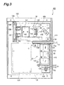
- Fig. 3 is a side view of a measuring device for immunochromatography test pieces relating to a second embodiment of the present invention;
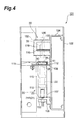
- Fig. 4 is a front view of a measuring device for immunochromatography test pieces relating to a second embodiment of the present invention;
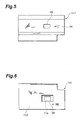
- Fig. 5 is a plan view of a test piece holder included in a measuring device for immunochromatography test pieces relating to a second embodiment of the present invention;
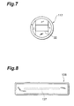
- Fig. 6 is a rear view of a test piece holder included in a measuring device for immunochromatography test pieces relating to a second embodiment of the present invention;
- Fig. 7 is a plan view of a lens mask included in a measuring device for immunochromatography test pieces relating to a second embodiment of the present invention;
- Fig. 8 is a plan view of a linear array CCD image sensor included in a measuring device for immunochromatography test pieces relating to a second embodiment;
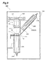
- Fig. 9 is a compositional view of a measuring device for immunochromatography test pieces relating to a third embodiment of the present invention; and
- Fig. 10 is a compositional view of a measuring device for immunochromatography test pieces relating to a third embodiment of the present invention.
-
- A measuring device for immunochromatography test pieces relating to an embodiment of the present invention is now described with reference to the drawings. In the respective drawings, similar elements or elements having similar functions are similarly labelled, and duplicated description thereof is omitted.
- Firstly, a
measuring device 1 for immunochromatography test pieces relating to a first embodiment is described with reference to Fig. 1. - The
measuring device 1 comprises an irradiatingoptical system 20 for irradiating measurement light onto animmunochromatography test piece 10, and a detectionoptical system 30 for detecting light from animmunochromatography test piece 10 by irradiation of the measurement light. The irradiationoptical system 20 comprises a light-emittingelement 21 and amixing rod 22. Moreover, the detectionoptical system 30 comprises anaperture 31, acylindrical lens 33 forming an imaging lens, and aCCD image sensor 36 forming an imaging element. - The
immunochromatography test piece 10 has a long rectangular shape and is made from a material such as a nitrocellulose membrane, or filter paper, or the like. Thisimmunochromatography test piece 10 is held inside acasing 11 having a long rectangular shape in plan view, and asubject application window 12,observation window 13 andcontrol window 14 are provided extending in the direction of the longer side in thecasing 11. Theimmunochromatography test piece 10 comprises asubject application section 15 provided in a position corresponding to thesubject application window 12, and detectingsections observation window 13 andcontrol window 14. The detectingsection 16 has a line shape (or band shape) formed by coating respective antigens (or antibodies) which react with antigens (or antibodies) in the subject, and causing same to solidify. Thecasing 11 which holds theimmunochromatography test piece 10 is held by holding means (not illustrated). Theobservation window 13 has a size of 4 mm x 8 mm, for example. - The subject is applied dropwise via the
subject application window 12 onto thesubject application section 15 of theimmunochromatography test piece 10. The antigens (or antibodies) in the subject couple with the indicator dye and the indicator dye coupled with the antigens (or antibodies) in the subject, as well as unreacted indicator dye, travel in the longitudinal direction of theimmunochromatography test piece 10. Supposing that the subject contains antigens, then it is assumed that the antigens will undergo an antigen/antibody reaction with the respective detecting sections. As the subject travels, the antigens in the subject and the antigens fixed to the detectingsection 16 react specifically and a line-shaped pattern 18 colored by the indicator dye is formed in the detectingsection 16 where reaction has taken place. This colored line-shaped pattern 18 is formed extending in a direction intersecting (for example, orthogonally) with the direction of travel of the antigens (or antibodies) of the subject in theimmunochromatography test piece 10, and it can be observed by means of theobservation window 13. - The light-emitting
element 21 comprises a plurality of LEDs having different light emission wavelengths, in the present embodiment, ablue LED 21B and ared LED 21R. If the line-shaped pattern 18 formed by the antigen/antibody reaction is colored red, then theblue LED 21B is caused to emit light. If the line-shaped pattern 18 formed by the antigen/antibody reaction is colored blue, then thered LED 21R is caused to emit light. - The
mixing rod 22 is a square-shaped (or circular-shaped) rod made from transparent acrylic resin for mixing the light output by the light-emitting element 21 (blue LED 21B orred LED 21R), and it has a light input face and a light output face at the respective ends thereof. The aforementioned light-emittingelement 21 is positioned on the light input face side of the mixingrod 22. An immunochromatography test piece 10 (casing 11) is positioned on the light output face side of the mixingrod 22. More specifically, the immunochromatography test piece 10 (casing 11) is positioned opposing the light output face of the mixingrod 22 in such a manner that theobservation window 13 of thecasing 11 coincides with the light output face of the mixingrod 22. The light output face of the mixingrod 22 has a size of 8 mm x 14 mm, and the surface area of the light output face of this mixingrod 22 is set to a larger area than the surface area of the opening in theobservation window 13 of thecasing 11. -
Diffusion plates rod 22, in a state of contact with the light input face and light output face of the mixingrod 22. These diffusingplates plates rod 22 into ground glass surfaces in order to provide diffusing means. - The light output from the light-emitting element 21 (
blue LED 21B orred LED 21R) is diffused by the diffusingplate 23 and then enters into the mixingrod 22 via the light input face of the mixingrod 22. The light that has entered the mixingrod 22 is mixed by being fully reflected at the side faces of the mixingrod 22 whilst it is propagated therein, and this mixed light arrives at the light output face of the mixingrod 22. The light arriving at the light output face of the mixingrod 22 is diffused by the diffusingplate 24, and is then irradiated as measurement light from the rear face of theobservation window 13 of thecasing 11 in the direction of the immunochromatography test piece 10 (observation window 13 of the casing 11). - The
cylindrical lens 33 is positioned in such a manner that the direction of the generating line of the curved face of thecylindrical lens 33 intersects (for example, orthogonally) with the direction of travel of the antigens (or antibodies) of the subject in theimmunochromatography test piece 10, in other words, in such a manner that it is facing in the direction of extension of the line-shapedpattern 18 formed by coloration of theimmunochromatography test piece 10. Thecylindrical lens 33 forms an image of the line-shapedpattern 18 formed in theimmunochromatography test piece 10, by means of the input transmitted light from the immunochromatography test piece 10 (casing 11). - The
aperture 31 is positioned on the light input face side of thecylindrical lens 33. A long rectangular-shapedslit 32 extending in the direction of the generating line of the curved face of thecylindrical lens 33 is formed in theaperture 31. Theslit 32 in theaperture 31 restricts the transmitted light which passes through the immunochromatography test piece 10 (casing 11) upon irradiation of measurement light and is emitted via theobservation window 13. - An
aperture 34 for restricting light other the light from theobservation window 13 from being input to thecylindrical lens 33 is provided on the light output face of the immunochromatography test piece 10 (casing 11). Ahole section 35 for passing the transmitted light from the immunochromatography test piece 10 (casing 11) is provided in theaperture 34. - The
CCD image sensor 36 has alight receiving face 37, which is situated at the position where an image of the transmitted light from the immunochromatography test piece 10 (casing 11) is formed by thecylindrical lens 33. Light-receiving elements are provided in a one-dimensional or two-dimensional array on the light-receivingface 37. TheCCD image sensor 36 detects the transmitted light from theimmunochromatography test piece 10 by capturing the image formed by thecylindrical lens 33 on thelight receiving face 37. - Next, a method for determining the concentration of the subject is described. When transmitted light from the
immunochromatography test piece 10 is detected by theCCD image sensor 36, the light absorption of the line-shapedpattern 18 formed by coloration is determined as described below, on the basis of the output signal from theCCD image sensor 36. Firstly, a light absorption profile of the transmitted light of theimmunochromatography test piece 10 is created as illustrated in Fig. 2, on the basis of the output signal intensity from theCCD image sensor 36 and the position of the light-receiving element (channel) of theCCD image sensor 36. Thereupon, the light absorption ABS is calculated by means of the following equation (1), taking To as the output signal intensity at a position in the created absorption profile corresponding to a portion of theimmunochromatography test piece 10 that is not colored, and taking Ti as the output light intensity at a position corresponding to a colored region thereof (line-shaped pattern 18). - When the light absorption ABS is calculated, the total quantity (concentration) of antibodies or antigens contained in the subjected is derived from the light absorption ABS, by referring to a previously created quantity characteristics graph.
- It is also possible to calculate the light absorption ABS on the basis of the following equation (2), taking Tao as the average output signal intensity at a position of the created absorption profile corresponding to a region of the immunochromatography test piece that is not colored, and Tai as the average output signal intensity at a position corresponding to a color region (line-shaped pattern).
- In this way, an irradiation
optical system 20 and a detectionoptical system 30 are provided in themeasuring device 1. The irradiationoptical system 20 comprises a light-emitting element 21 (blue LED 21B orred LED 21R), and a mixingrod 22, and the light emitted from the mixingrod 22 is irradiated as measurement light onto the immunochromatography test piece 10 (casing 11). The detectionoptical system 30 comprises acylindrical lens 33 andCCD image sensor 36, and detects transmitted light from the immunochromatography test piece 10 (casing 11) by means of theCCD image sensor 36. Since the light output by the light-emittingelements 21 is mixed by the mixingrod 22 before being irradiated onto the immunochromatography test piece 10 (casing 11), attenuation of the light from the light-emittingelements 21 is suppressed, and the amount of light irradiated onto theimmunochromatography test piece 10 is increased. Consequently, theCCD image sensor 36 is able reliably to detect a line-shapedpattern 18 formed by coloration of theimmunochromatography test piece 10. Moreover, since light-emitting elements 21 (ablue LED 21B and ared LED 21R) are used, it is possible to suppress increase in the size of the measuringdevice 1. - Furthermore, in the
measuring device 1, since diffusingplates rod 22, the light irradiated onto the immunochromatography test piece 10 (casing 11) is approximately equalized. Thereby, it is possible to perform detection of the line-shapedpattern 18 in theimmunochromatography test piece 10 by means of theCCD image sensor 36 with even greater reliability. - Furthermore, in the
measuring device 1, since the surface area of the light output face of the mixingrod 22 is greater than the surface area of theobservation window 13 of thecasing 11, the light irradiated onto a position corresponding to theobservation window 13 of theimmunochromatography test piece 10 will be further equalized. Thereby, the detection of the line-shapedpattern 18 in theimmunochromatography test piece 10 by means of theCCD image sensor 36 can be performed with even greater reliability. - Moreover, the measuring
device 1 has acylindrical lens 33 forming an imaging lens, thiscylindrical lens 33 being provided in such a manner that the direction of the generating line of the curved face thereof intersects with the direction of travel of the antigens or antibodies in theimmunochromatography test piece 10, and due to irradiation of measurement light, an image of the line-shapedpattern 18 formed in a direction intersecting with the direction of travel of the antigens or antibodies is formed on theCCD image sensor 36. Thereby, light which is parallel to the direction of travel of the antigens or antibodies in theimmunochromatography test piece 10 is formed as an image on theCCD image sensor 36, and light which is orthogonal to the direction of travel of the antigens or antibodies in theimmunochromatography test piece 10 is defocused and equalized. Consequently, even if uneven coloration occurs in the direction of extension of the line-shapedpattern 18 formed by coloration of theimmunochromatography test piece 10, the uneven coloration is equalized optically by thecylindrical lens 33, and a pattern wherein the uneven discoloration is equalized optically is formed as an image on theCCD image sensor 36. As a result, the degree of coloration of the line-shapedpattern 18 formed in theimmunochromatography test piece 10 can be measured with good accuracy. - Furthermore, in the
measuring device 1, since theaperture 31 formed with a long rectangular-shapedslit 32 extending in the direction of the generating line of the curved face of thecylindrical lens 33 is disposed on the light input face side of thecylindrical lens 33, it is possible to focus an image having little aberration on theCCD image sensor 36. - Moreover, the irradiation
optical system 20 and detectionoptical system 30 in themeasuring device 1 are positioned in such a manner that theCCD image sensor 36 receives the transmitted light of the measurement light irradiated onto theimmunochromatography test piece 10, and the light absorption of the line-shapedpattern 18 formed by coloration is measured on the basis of the transmitted light received by theCCD image sensor 36. Thereby, the degree of coloration of the line-shapedpattern 18 formed in theimmunochromatography test piece 10 can be measured simply and very accurately, and the total amount (concentration) of antigens or antibodies contained in the subject can be measured precisely. - Next, the measuring
device 101 for an immunochromatography test piece relating to a second embodiment is described with reference to Figs. 3 to 8. The measuringdevice 101 relating to the second embodiment differs from the measuringdevice 1 relating to the first embodiment in that the light path is constituted in a bent fashion by using mirrors. - As shown in Fig. 3 and Fig. 4, the measuring
device 101 comprises acase 102, and a lid (not illustrated) which fits onto thecase 102. Achassis 104 is fitted inside thecase 102 in order to position an irradiationoptical system 20, a detectionoptical system 30, and acontrol circuit 103 for controlling the operation of the measuringdevice 101 by performing various calculation processes. - The light-emitting elements 21 (
blue LED 21B orred LED 21R) are fixed to aninstallation plate 105, and thisinstallation plate 105 is attached to thechassis 104 via abracket 106. - A mixing
rod 22 is situated inside arod case 107, in a state whereby the light input face and light output face of the mixingrod 22contact diffusion plates rod 22 in the direction of the light guide is limited by means of a restrictingsection 108 formed integrally with therod case 107 confronting thediffusion plate 24, and arod pressing plate 109 combined with therod case 107 confronting thediffusion plate 23. A plurality ofrod holders 110 are installed on the side face of the mixingrod 22, at prescribed intervals in the light guide direction of the mixingrod 22. The position of the mixingrod 22 in the direction orthogonal to the light guide direction thereof is limited by means of theserod holders 110 confronting the side walls of therod case 107. - A
test piece holder 111 constituted so that an immunochromatography test piece 10 (casing 11) can be inserted therein, is provided on the upper face of the restricting section 108 (rear side of the face confronting the diffusion plate 24). Thistest piece holder 111 functions as holding means for holding the immunochromatography test piece 10 (casing 11). - The
test piece holder 111 is constituted in such a manner that, thecasing 11 makes contact with theaperture 34, when it is inserted inside thetest piece holder 111 and positioned in a testpiece installation section 112 formed integrally with theaperture 34. Thetest piece holder 111 is installed on thechassis 104 in a state where the restrictingsection 108 and testpiece installation section 112 are in mutual contact. The insertion position of the immunochromatography test piece 10 (casing 11) in the longitudinal direction is restricted by means of a restrictingsection 113 formed integrally with the rod case 107 (restricting section 108) making contact with the end of thecasing 11 in the longitudinal direction thereof. - As shown in Fig. 5, a
hole section 35 for passing transmitted light from the immunochromatography test piece 10 (casing 11) is provided in theaperture 34. Thehole section 35 of theaperture 34 has a size of 5 mm × 8 mm. Furthermore, as shown in Fig. 6, a hole section 214 for irradiating light from thediffusion plate 24 onto the immunochromatography test piece 10 (casing 11) is provided on the testpiece installation section 112 of thetest piece holder 111. Thehole section 114 of the testpiece installation section 112 has a size of 8 mm × 14 mm. The light output face of the mixingrod 22 also has a size of 8 mm × 14 mm. The observation window has a size of 4 mm × 8 mm. - A
mirror 115 is provided on top of thetest piece holder 111. Thismirror 115 is installed on thechassis 104 via amirror holder 116. The light reflected by themirror 115 is input to thecylindrical lens 33. The light path is bent in themeasuring device 101 by means of thismirror 115, and as illustrated in Fig. 3, the irradiationoptical system 20 and the detectionoptical system 30 are located in an inverse L shape. Thecontrol circuit 103 is installed on thechassis 104 in a position to the inner side of the irradiationoptical system 20 and detectionoptical system 30 provided in an inverse L shape. By laying out the irradiationoptical system 20, detectionoptical system 30 andcontrol circuit 103 in this way, it is possible to achieve compactification of the measuringdevice 101. - The
cylindrical lens 33 is positioned in such a manner that the direction of the generating line of the curved face of thecylindrical lens 33 intersects (orthogonally, for example,) with the direction of travel of the antigens (or antibodies) of the subject in theimmunochromatography test piece 10, in other words, in such a manner that it faces in the direction of extension of the line-shapedpattern 18 formed by coloration in theimmunochromatography test piece 10. Alens mask 117 forming an aperture is positioned on the light input side of thecylindrical lens 33. As shown in Fig. 7, a longrectangular slit 32 extending in the direction of the generating line of the curved face of thecylindrical lens 33 is formed in thelens mask 117. The size of this slit 32 is set to 4 mm × 8 mm. - The
cylindrical lens 33 andlens mask 117 are held on either side by alens holder 118 andpressing ring 119, by means of thelens holder 118 andpressing ring 119 being screw fitted together. Thelens holder 118 is fixed in a state where it is inserted into a hole section of alens installation tube 120. Thelens installation tube 120 with thelens holder 118 fixed thereto is installed on thechassis 104. - Light exiting the
cylindrical lens 33 is incident on a linear arrayCCD image sensor 136. The linear arrayCCD image sensor 136 has alight receiving face 137 extending in a one-dimensional direction, as illustrated in Fig. 8. The linear arrayCCD image sensor 136 is disposed in such a manner that thelight receiving face 137 thereof is positioned at the point where the transmitted light from the immunochromatography test piece 10 (casing 11) is formed into an image by thecylindrical lens 33. A plurality of light-receiving elements (in the present embodiment, 2048 elements) are disposed in a one-dimensional fashion on thelight receiving face 137 of the linear arrayCCD image sensor 136. The linear arrayCCD image sensor 136 is fixed to asensor holder 139 by means of asubstrate 138, and thissensor holder 139 is attached to thechassis 104 via asensor installation tube 140. As shown in Fig. 3, the direction of extension of thelight receiving face 137 of the linear arrayCCD image sensor 136 is a direction which intersects with the direction of the generating line of the curved face of thecylindrical lens 33, when the linear arrayCCD image sensor 136 is installed in thechassis 104. - A
baffle plate 141 for eliminating stray light is provided between thecylindrical lens 33 and the linear arrayCCD image sensor 136.Hole sections cylindrical lens 33 are formed in thisbaffle plate 141. Thebaffle plate 141 is installed on thechassis 104. - The detection optical system from the
aperture 34 to the linear arrayCCD image sensor 136 is covered by alight shielding tube 150 in order to optically shield this detection optical system. Thelight shielding tube 150 is installed on thechassis 104. - The measuring
device 101 having the foregoing composition provides the same action and beneficial effects as the measuringdevice 1 relating to the first embodiment and is able reliably to detect a line-shapedpattern 18 formed by coloration of animmunochromatography test piece 10, by means of the linear arrayCCD image sensor 136. Moreover, since light-emitting elements 21 (blue LED 21B orred LED 21R) are used as light sources, it is possible to prevent increase in the size of the measuringdevice 101. - Furthermore, the measuring
device 101 has acylindrical lens 33 as an imaging lens, and thiscylindrical lens 33 is disposed so that the direction of the generating line of the curved face thereof intersects with the direction of travel of the antigens or antibodies in theimmunochromatography test piece 10, and it forms an image of the line-shapedpattern 18 formed in a direction intersecting with the direction of travel of the antigens or antibodies, on the linear arrayCCD image sensor 136, due to irradiation of measurement light. Thereby, light that is parallel to the direction of travel of the antigens or antibodies in theimmunochromatography test piece 10 is formed as an image on the linear arrayCCD image sensor 136, and light that is orthogonal to the direction of travel of the antigens or antibodies in theimmunochromatography test piece 10 is defocused and equalized. Consequently, even if uneven coloration occurs in the direction of extension of the line-shapedpattern 18 formed by coloration of theimmunochromatography test piece 10, this uneven coloration will be optically equalized by thecylindrical lens 33, and hence a pattern wherein uneven coloration is optically equalized will be formed as an image on the linear arrayCCD image sensor 136. As a result, it is possible to measure the degree of coloration of the line-shapedpattern 18 formed on theimmunochromatography test piece 10 to a high level of accuracy. - Moreover, in the
measuring device 101, since alens mask 117 formed with a longrectangular slit 32 extending in the direction of the generating line of the curved face of thecylindrical lens 33 is provided at the light input face of thecylindrical lens 33, it is possible to form an image having little aberration on the linear arrayCCD image sensor 136. - Moreover, in the
measuring device 101, since a linear arrayCCD image sensor 136 is used as an imaging element, a measuringdevice 101 having an inexpensive and compact composition can be achieved. As described above, since any unevenness in coloration is optically equalized by thecylindrical lens 33, it is possible to measure the degree of coloration of the line-shapedpattern 18 formed in theimmunochromatography test piece 10 with a high level of accuracy, even if a linear arrayCCD image sensor 136 is used as an imaging element. - Next, a measuring
device 201 for immunochromatography test pieces relating to a third embodiment is described on the basis of Fig. 9 to Fig. 10. The measuringdevice 201 relating to the third embodiment differs from the measuringdevices - In the
measuring device 201, the irradiationoptical system 20 comprises a first irradiationoptical system 20A for irradiating measurement light from the rear side of an immunochromatography test piece 10 (casing 11), and a second irradiationoptical system 20B for irradiating measurement light from the front side of an immunochromatography test piece 10 (casing 11). The immunochromatography test piece 10 (casing 11) is held in atest piece holder 111 forming holding means. - The first irradiation
optical system 20A comprises, as a light-emitting element, ared LED 21R (orblue LED 21B), and afirst mixing rod 22A. The light input face and light output face of afirst mixing rod 22A are processed to ground glass faces. - Light output from the
red LED 21R (orblue LED 21B) is diffused by the ground glass face of the light input face of thefirst mixing rod 22A, and enters into thefirst mixing rod 22A. The light that has entered into thefirst mixing rod 22A is mixed by total reflection at the side faces of thefirst mixing rod 22A as it propagates therein, and it is diffused and output from the light output face of thefirst mixing rod 22A. The light exiting thefirst mixing rod 22A is irradiated onto the immunochromatography test piece 10 (observation window 13 of casing 11) as measurement light, from the rear side of theobservation window 13 of thecasing 11. - The second irradiation
optical system 20B comprises ablue LED 21B (orred LED 21R) as a light-emitting element, asecond mixing rod 22B, and a condensinglens 202. The light input face and light output face of thesecond mixing rod 22B are processed to ground glass faces, similarly to thefirst mixing rod 22A. - Light emitted by the
blue LED 21B (orred LED 21R) is diffused by the ground glass face of the light input face of thefirst mixing rod 22B, and enters into thesecond mixing rod 22B. The light that has entered into thesecond mixing rod 22B is mixed by total reflection at the side faces of thesecond mixing rod 22B as it propagates therein, and it is diffused and output from the light output face of thesecond mixing rod 22B. The light exiting thesecond mixing rod 22B is condensed by the condensinglens 202, and is then irradiated onto the immunochromatography test piece 10 (observation window 13 of casing 11) as measurement light, via theobservation window 13 of thecasing 11. - The measurement light irradiated from the first irradiation
optical system 20A is received and detected as transmitted light from the immunochromatography test piece 10 (casing 11) by the linear arrayCCD image sensor 136. Furthermore, the measurement light irradiated from the second irradiationoptical system 20B is received as detected as reflected light from the immunochromatography test piece 10 (casing 11) by the linear arrayCCD image sensor 136. - A
cylindrical lens 33 is positioned in such a manner that the direction of the generating line of the curved face of thecylindrical lens 33 intersects (orthogonally, for example,) with the direction of travel of the antigens (or antibodies) of the subject in theimmunochromatography test piece 10, in other words, in such a manner that it faces in the direction of extension of the line-shapedpattern 18 formed by coloration in theimmunochromatography test piece 10. Alens mask 117 formed with a longrectangular slit 32 extending in the direction of the generating line of the curved face of thecylindrical lens 33 is disposed at the light input face of thecylindrical lens 33. The linear arrayCCD image sensor 136 is disposed in such a manner that the direction of extension of thelight receiving face 137 of the linear arrayCCD image sensor 136 intersects (orthogonally, for example) with the direction of the generating line of the curved face of thecylindrical lens 33. - The measuring
device 201 having the foregoing composition provides the same action and beneficial effects as themeasuring devices pattern 18 formed by coloration of animmunochromatography test piece 10, by means of the linear arrayCCD image sensor 136. Moreover, since light-emitting elements 21 (blue LED 21B orred LED 21R) are used as light sources, it is possible to prevent increase in the size of the measuringdevice 201. - Furthermore, the measuring
device 201 has acylindrical lens 33 as an imaging lens, and thiscylindrical lens 33 is disposed so that the direction of the generating line of the curved face thereof intersects with the direction of travel of the antigens or antibodies in theimmunochromatography test piece 10. Consequently, even if uneven coloration occurs in the direction of extension of the line-shapedpattern 18 formed by coloration of theimmunochromatography test piece 10, this uneven coloration will be optically equalized by thecylindrical lens 33, and hence a pattern wherein uneven coloration is optically equalized will be formed as an image on the linear arrayCCD image sensor 136. As a result, it is possible to measure the degree of coloration of the line-shapedpattern 18 formed on theimmunochromatography test piece 10 to a high level of accuracy. - Moreover, in the
measuring device 201, the irradiationoptical system 20 and detectionoptical system 30 are disposed in such a manner that the linear arrayCCD image sensor 136 receives both transmitted light and reflected light of the measurement light irradiated onto theimmunochromatography test piece 10, and the light absorption of the line-shapedpattern 18 formed by coloration is measured on the basis of the transmitted light or reflectivity thus received by the linear arrayCCD image sensor 136. Accordingly, the degree of coloration of the line-shapedpattern 18 formed on theimmunochromatography test piece 10 can be measured simply and very accurately, and hence the total amount (concentration) of antigens or antibodies contained in the subject can be measured precisely. - If the concentration of antigens or antibodies is very low, then the degree of coloration will be low and the amount of detected light is very weak. In cases where the concentration of antigens or antibodies is very low in this way, it is beneficial to use light absorption measurement based on the transmitted light. Moreover, if the concentration of the antigens or antibodies is high and the amount of detected light is high, then measurement of the reflectivity based on the reflected light is performed. As described above, it is possible to measure the concentration of antigens or antibodies, accurately across a wide range, by selective use of transmitted light measurement or reflected light measurement, according to the concentration of the antigens or antibodies.
- The present invention is not limited to the foregoing embodiments, and the aforementioned numerical values, and the like, may also be changed appropriately.
- Moreover, in the
measuring devices CCD image sensor pattern 18 formed in theimmunochromatography test piece 10 is measured on the basis of the transmitted light thus received by theCCD image sensor CCD image sensor measuring devices pattern 18 formed in theimmunochromatography test piece 10 on the basis of the reflected light thus received by theCCD image sensor - The present invention is applicable to a measuring device for immunochromatography test pieces used in pregnancy examinations, occult blood in faeces examinations, and the like.
Claims (5)
- A measuring device for immunochromatography test pieces, comprising an irradiation optical system for irradiating measurement light onto immunochromatography test pieces; and a detection optical system for detecting light from said immunochromatography test pieces due to said measurement light;
characterized in that said detection optical system comprises a cylindrical lens and an imaging element; and
said cylindrical lens is disposed in such a manner that the direction of the generating line thereof intersects with the direction of travel of antigens or antibodies in said immunochromatography test piece, and creates an image of a pattern formed in a direction intersecting with the direction of travel of said antigens or antibodies, on said imaging element, due to the irradiation of said measurement light from said irradiation optical system. - The measuring device for immunochromatography test pieces according to claim 1, characterized in that a member having a slit formed to extend in the direction of the generating line of said cylindrical lens is further provided between said immunochromatography test piece and said cylindrical lens.
- The measuring device for immunochromatography test pieces according to claim 1, characterized in that said imaging element is a linear image sensor wherein a plurality of light-receiving elements are arrayed in a direction approximately orthogonal to the direction of the generating line of said cylindrical lens.
- The measuring device for immunochromatography test pieces according to claim 1, wherein said irradiation optical system and said detection optical system are disposed in such a manner that said imaging element receives the transmitted light of said measurement light irradiated onto said immunochromatography test piece; and
the light absorption of said color pattern is measured on the basis of said transmitted light received by said imaging element. - The measuring device for immunochromatography test pieces according to claim 1, wherein said irradiation optical system and said detection optical system are disposed in such a manner that said imaging element receives the reflected light of said measurement light irradiated onto said immunochromatography test piece; and
the reflectivity of said color pattern is measured on the basis of said reflected light received by said imaging element.
Applications Claiming Priority (3)
| Application Number | Priority Date | Filing Date | Title |
|---|---|---|---|
| JP2000111144 | 2000-04-12 | ||
| JP2000111144A JP4188538B2 (en) | 2000-04-12 | 2000-04-12 | Immunochromatographic test piece measuring device |
| PCT/JP2001/002990 WO2001077679A1 (en) | 2000-04-12 | 2001-04-06 | Measuring method for immunochromatographic test strip |
Publications (2)
| Publication Number | Publication Date |
|---|---|
| EP1275964A1 true EP1275964A1 (en) | 2003-01-15 |
| EP1275964A4 EP1275964A4 (en) | 2003-06-04 |
Family
ID=18623535
Family Applications (1)
| Application Number | Title | Priority Date | Filing Date |
|---|---|---|---|
| EP01919809A Withdrawn EP1275964A4 (en) | 2000-04-12 | 2001-04-06 | Measuring Method for immunochromatographic Test Strip |
Country Status (5)
| Country | Link |
|---|---|
| US (1) | US6819422B2 (en) |
| EP (1) | EP1275964A4 (en) |
| JP (1) | JP4188538B2 (en) |
| AU (1) | AU2001246854A1 (en) |
| WO (1) | WO2001077679A1 (en) |
Cited By (4)
| Publication number | Priority date | Publication date | Assignee | Title |
|---|---|---|---|---|
| EP1605248A1 (en) * | 2003-02-26 | 2005-12-14 | Hamamatsu Photonics K.K. | Device for measuring immunochromatography test piece |
| WO2009095679A2 (en) * | 2008-02-01 | 2009-08-06 | Cambridge Consultants Limited | Photometric pevice |
| EP2325624A1 (en) * | 2009-11-18 | 2011-05-25 | F. Hoffmann-La Roche AG | Method and device for inspecting a bodily fluid |
| EP1447658B1 (en) * | 2003-02-11 | 2015-10-21 | Bayer HealthCare LLC | Multiwavelength readhead for use in the determination of analytes in body fluids |
Families Citing this family (27)
| Publication number | Priority date | Publication date | Assignee | Title |
|---|---|---|---|---|
| EP2077443A3 (en) | 2000-09-25 | 2010-01-13 | Panasonic Corporation | Chromatography quantitative measuring apparatus |
| JP2003004743A (en) * | 2001-06-22 | 2003-01-08 | Matsushita Electric Ind Co Ltd | Chromatographic quantitative measurement apparatus |
| JP4797233B2 (en) * | 2000-09-25 | 2011-10-19 | パナソニック株式会社 | Compact sample concentration measuring device |
| JP4984355B2 (en) * | 2001-07-16 | 2012-07-25 | パナソニック株式会社 | Chromatographic quantitative measurement device |
| JP4734495B2 (en) * | 2003-01-30 | 2011-07-27 | ハッチンソン,マイケル | Method and apparatus for processing analytical test results |
| US7173704B2 (en) * | 2003-02-26 | 2007-02-06 | Hamamatsu Photonics K.K. | Measuring device for immunochromatography test piece and light source device |
| WO2005114043A1 (en) * | 2004-05-14 | 2005-12-01 | Allsop, Inc. | Offset solar-powered outdoor lighting apparatus |
| US7264971B2 (en) * | 2004-07-20 | 2007-09-04 | Siemens Medical Solutions Diagnostics | Read-head for optical diagnostic device |
| US20060262522A1 (en) * | 2005-05-18 | 2006-11-23 | Allsop James D | Offset solar-powered outdoor lighting apparatus |
| US7891832B2 (en) * | 2005-05-18 | 2011-02-22 | Allsop, Inc. | Outdoor light with positionable solar collector |
| US8789756B2 (en) * | 2006-02-25 | 2014-07-29 | Roche Diagnostics Operations, Inc. | Test element coding apparatuses, systems and methods |
| JP5174496B2 (en) * | 2008-03-13 | 2013-04-03 | グローリー株式会社 | Optical sensor module |
| KR101025723B1 (en) * | 2008-07-18 | 2011-04-04 | 주식회사 인포피아 | An immunochromatography detection sensor comprising optical waveguide and a detection method using the same |
| JP5928343B2 (en) * | 2010-12-20 | 2016-06-01 | コニカミノルタ株式会社 | Chromatography analyzer |
| JP5146565B2 (en) * | 2011-05-13 | 2013-02-20 | パナソニック株式会社 | Chromatographic quantitative measurement method |
| JP5093379B2 (en) * | 2011-05-13 | 2012-12-12 | パナソニック株式会社 | Chromatography quantitative measurement method |
| JP5093380B2 (en) * | 2011-05-13 | 2012-12-12 | パナソニック株式会社 | Chromatographic quantitative measurement method |
| JP5083433B2 (en) * | 2011-05-30 | 2012-11-28 | パナソニック株式会社 | Chromatographic quantitative measurement device |
| JP5554289B2 (en) * | 2011-06-13 | 2014-07-23 | 古河電気工業株式会社 | Detection apparatus for immunochromatography and detection method thereof |
| ES2890752T3 (en) | 2012-02-06 | 2022-01-21 | Univ California | Portable Rapid Diagnostic Test Reader |
| CN105090810A (en) * | 2014-05-16 | 2015-11-25 | 科宝智慧医疗科技(上海)有限公司 | Illumination device |
| CN104730000A (en) * | 2015-04-13 | 2015-06-24 | 大连理工大学 | Photoelectric quantitative testing device for immune chromatography reaction results |
| US9839088B1 (en) | 2016-03-10 | 2017-12-05 | Heathco, Llc | Security light with remote photo-voltaic module and battery backup and related methods |
| CN106568933A (en) * | 2016-10-31 | 2017-04-19 | 深圳市安鑫宝科技发展有限公司 | Aquatic animal diagnosing instrument |
| CN109239338B (en) * | 2018-10-09 | 2023-09-08 | 邱华遗 | Wide-range immunochromatography detection device and method |
| US10718500B1 (en) | 2019-08-30 | 2020-07-21 | HealthCo LLC | Solar powered security light with variable mounting |
| EP4317977A1 (en) * | 2021-03-30 | 2024-02-07 | FUJIFILM Corporation | Test device and cartridge |
Citations (9)
| Publication number | Priority date | Publication date | Assignee | Title |
|---|---|---|---|---|
| US4119381A (en) * | 1976-12-17 | 1978-10-10 | Eastman Kodak Company | Incubator and radiometric scanner |
| US4510383A (en) * | 1981-09-18 | 1985-04-09 | Boehringer Mannheim Gmbh | Device for the optical identification of a coding on a diagnostic test strip |
| US4537861A (en) * | 1983-02-03 | 1985-08-27 | Elings Virgil B | Apparatus and method for homogeneous immunoassay |
| EP0469377A2 (en) * | 1990-08-02 | 1992-02-05 | Roche Diagnostics GmbH | Analysis system and method for the determination of an analyte in a liquid sample |
| JPH0552809A (en) * | 1991-08-28 | 1993-03-02 | Hitachi Software Eng Co Ltd | Method and apparatus for reading fluorescent pattern |
| RU2018891C1 (en) * | 1991-02-01 | 1994-08-30 | Алексей Валерьевич Карнаухов | Confocal scanning microscope |
| WO1996039621A1 (en) * | 1995-06-06 | 1996-12-12 | Boehringer Mannheim Gmbh | Device for use in the optical investigation of surfaces |
| WO1998053301A2 (en) * | 1997-05-23 | 1998-11-26 | Becton Dickinson And Company | Automated microbiological testing apparatus and methods therefor |
| US6025601A (en) * | 1994-09-02 | 2000-02-15 | Affymetrix, Inc. | Method and apparatus for imaging a sample on a device |
Family Cites Families (11)
| Publication number | Priority date | Publication date | Assignee | Title |
|---|---|---|---|---|
| JPH0629847B2 (en) * | 1985-05-16 | 1994-04-20 | 株式会社島津製作所 | Chromatoskiana |
| SE462408B (en) * | 1988-11-10 | 1990-06-18 | Pharmacia Ab | OPTICAL BIOSENSOR SYSTEM USING SURFACE MONITORING RESONSE FOR THE DETECTION OF A SPECIFIC BIOMOLIC CYCLE, TO CALIBRATE THE SENSOR DEVICE AND TO CORRECT FOUND BASELINE OPERATION IN THE SYSTEM |
| EP0448931B1 (en) * | 1990-01-26 | 1996-04-03 | Canon Kabushiki Kaisha | Method for measuring a specimen by the use of fluorescence light |
| JP2516112B2 (en) * | 1991-08-13 | 1996-07-10 | 日立ソフトウエアエンジニアリング株式会社 | Nucleic acid electrophoresis pattern reading method |
| JP3559975B2 (en) | 1992-09-10 | 2004-09-02 | テラメックス株式会社 | Analysis method using test pieces |
| US5770389A (en) * | 1993-09-27 | 1998-06-23 | Abbott Laboratories | Apparatus and method for determining the quanity of an analyte in a biological sample by means of transmission photometry |
| DK0653625T3 (en) | 1993-11-12 | 2003-01-13 | Inverness Medical Switzerland | Test strip reading devices |
| JP3541232B2 (en) * | 1995-06-05 | 2004-07-07 | テラメックス株式会社 | Method for measuring the degree of coloration of immunochromatographic test strips |
| US6245507B1 (en) * | 1998-08-18 | 2001-06-12 | Orchid Biosciences, Inc. | In-line complete hyperspectral fluorescent imaging of nucleic acid molecules |
| JP2000121562A (en) | 1998-10-15 | 2000-04-28 | Ebisu Denki Kk | Device for quantitatively determining coloring substance and storage medium for quantitatively determining coloring substance |
| US6134002A (en) * | 1999-01-14 | 2000-10-17 | Duke University | Apparatus and method for the rapid spectral resolution of confocal images |
-
2000
- 2000-04-12 JP JP2000111144A patent/JP4188538B2/en not_active Expired - Fee Related
-
2001
- 2001-04-06 WO PCT/JP2001/002990 patent/WO2001077679A1/en not_active Application Discontinuation
- 2001-04-06 EP EP01919809A patent/EP1275964A4/en not_active Withdrawn
- 2001-04-06 US US10/257,440 patent/US6819422B2/en not_active Expired - Lifetime
- 2001-04-06 AU AU2001246854A patent/AU2001246854A1/en not_active Abandoned
Patent Citations (9)
| Publication number | Priority date | Publication date | Assignee | Title |
|---|---|---|---|---|
| US4119381A (en) * | 1976-12-17 | 1978-10-10 | Eastman Kodak Company | Incubator and radiometric scanner |
| US4510383A (en) * | 1981-09-18 | 1985-04-09 | Boehringer Mannheim Gmbh | Device for the optical identification of a coding on a diagnostic test strip |
| US4537861A (en) * | 1983-02-03 | 1985-08-27 | Elings Virgil B | Apparatus and method for homogeneous immunoassay |
| EP0469377A2 (en) * | 1990-08-02 | 1992-02-05 | Roche Diagnostics GmbH | Analysis system and method for the determination of an analyte in a liquid sample |
| RU2018891C1 (en) * | 1991-02-01 | 1994-08-30 | Алексей Валерьевич Карнаухов | Confocal scanning microscope |
| JPH0552809A (en) * | 1991-08-28 | 1993-03-02 | Hitachi Software Eng Co Ltd | Method and apparatus for reading fluorescent pattern |
| US6025601A (en) * | 1994-09-02 | 2000-02-15 | Affymetrix, Inc. | Method and apparatus for imaging a sample on a device |
| WO1996039621A1 (en) * | 1995-06-06 | 1996-12-12 | Boehringer Mannheim Gmbh | Device for use in the optical investigation of surfaces |
| WO1998053301A2 (en) * | 1997-05-23 | 1998-11-26 | Becton Dickinson And Company | Automated microbiological testing apparatus and methods therefor |
Non-Patent Citations (2)
| Title |
|---|
| PATENT ABSTRACTS OF JAPAN vol. 017, no. 357 (P-1568), 6 July 1993 (1993-07-06) & JP 05 052809 A (HITACHI SOFTWARE ENG CO LTD), 2 March 1993 (1993-03-02) * |
| See also references of WO0177679A1 * |
Cited By (10)
| Publication number | Priority date | Publication date | Assignee | Title |
|---|---|---|---|---|
| EP1447658B1 (en) * | 2003-02-11 | 2015-10-21 | Bayer HealthCare LLC | Multiwavelength readhead for use in the determination of analytes in body fluids |
| EP1605248A1 (en) * | 2003-02-26 | 2005-12-14 | Hamamatsu Photonics K.K. | Device for measuring immunochromatography test piece |
| CN100487424C (en) * | 2003-02-26 | 2009-05-13 | 浜松光子学株式会社 | Device for measuring immunochromatography test piece |
| EP1605248A4 (en) * | 2003-02-26 | 2012-03-14 | Hamamatsu Photonics Kk | Device for measuring immunochromatography test piece |
| WO2009095679A2 (en) * | 2008-02-01 | 2009-08-06 | Cambridge Consultants Limited | Photometric pevice |
| WO2009095679A3 (en) * | 2008-02-01 | 2009-12-10 | Cambridge Consultants Limited | Device and method for measuring scattering of radiation |
| US8742368B2 (en) | 2008-02-01 | 2014-06-03 | Cambridge Consultants Limited | Device and method for measuring scattering of radiation |
| EP2325624A1 (en) * | 2009-11-18 | 2011-05-25 | F. Hoffmann-La Roche AG | Method and device for inspecting a bodily fluid |
| WO2011061257A1 (en) * | 2009-11-18 | 2011-05-26 | Roche Diagnostics Gmbh | Method and device for analyzing a body fluid |
| US8570519B2 (en) | 2009-11-18 | 2013-10-29 | Roche Diagnostics Operations, Inc. | Method and device for analyzing a body fluid |
Also Published As
| Publication number | Publication date |
|---|---|
| JP4188538B2 (en) | 2008-11-26 |
| WO2001077679A1 (en) | 2001-10-18 |
| US20030098976A1 (en) | 2003-05-29 |
| EP1275964A4 (en) | 2003-06-04 |
| AU2001246854A1 (en) | 2001-10-23 |
| JP2001296246A (en) | 2001-10-26 |
| US6819422B2 (en) | 2004-11-16 |
Similar Documents
| Publication | Publication Date | Title |
|---|---|---|
| US6819422B2 (en) | Measuring method for immunochromatographic test strip | |
| KR100816799B1 (en) | Test element analysis system and method for analytical investigation using the same | |
| US6879399B2 (en) | Measuring method for immunochromatographic test strip | |
| EP1249696B1 (en) | Device for chromatographic quantitative measurement | |
| US5039225A (en) | Apparatus for measurement of reflection density | |
| EP1605248A1 (en) | Device for measuring immunochromatography test piece | |
| US20220113254A1 (en) | An apparatus and method for detecting photoluminescent light emitted from a sample | |
| JP2007225400A (en) | Optical detector | |
| JP2002267664A (en) | Measuring apparatus for immunochromatographic test piece | |
| JP4128730B2 (en) | Immunochromatographic test piece measuring device | |
| JP2011089917A (en) | Testpiece housing and immunochromatographic device for concentration measurement | |
| US20210148829A1 (en) | Reading device for a lateral flow test strip | |
| US6804007B2 (en) | Apparatus for multiplexing two surface plasma resonance channels onto a single linear scanned array | |
| JP2533845B2 (en) | Immunological analysis method | |
| CN117233094A (en) | Detection assembly and detection device | |
| CN117233092A (en) | Detection assembly and detection device | |
| CN117233095A (en) | Detection assembly and detection device | |
| JPH04301744A (en) | Prism for micro-total refection measurement | |
| JPH02156139A (en) | Light source apparatus for measuring concentration | |
| JPH0213829A (en) | Particle measuring apparatus |
Legal Events
| Date | Code | Title | Description |
|---|---|---|---|
| PUAI | Public reference made under article 153(3) epc to a published international application that has entered the european phase |
Free format text: ORIGINAL CODE: 0009012 |
|
| 17P | Request for examination filed |
Effective date: 20021105 |
|
| AK | Designated contracting states |
Kind code of ref document: A1 Designated state(s): AT BE CH CY DE DK ES FI FR GB GR IE IT LI LU MC NL PT SE TR |
|
| AX | Request for extension of the european patent |
Free format text: AL;LT;LV;MK;RO;SI |
|
| A4 | Supplementary search report drawn up and despatched |
Effective date: 20030423 |
|
| RIC1 | Information provided on ipc code assigned before grant |
Ipc: 7G 01N 33/558 B Ipc: 7G 01N 21/17 B Ipc: 7G 01N 31/22 B Ipc: 7G 01N 33/52 B Ipc: 7G 01N 33/543 A |
|
| RTI1 | Title (correction) |
Free format text: MEASURING METHOD FOR IMMUNOCHROMATOGRAPHIC TEST STRIP |
|
| RBV | Designated contracting states (corrected) |
Designated state(s): CH DE FR GB LI |
|
| 17Q | First examination report despatched |
Effective date: 20061023 |
|
| STAA | Information on the status of an ep patent application or granted ep patent |
Free format text: STATUS: THE APPLICATION IS DEEMED TO BE WITHDRAWN |
|
| 18D | Application deemed to be withdrawn |
Effective date: 20070303 |