EP1274208A1 - Communication device and transmission mode selecting method - Google Patents
Communication device and transmission mode selecting method Download PDFInfo
- Publication number
- EP1274208A1 EP1274208A1 EP02700655A EP02700655A EP1274208A1 EP 1274208 A1 EP1274208 A1 EP 1274208A1 EP 02700655 A EP02700655 A EP 02700655A EP 02700655 A EP02700655 A EP 02700655A EP 1274208 A1 EP1274208 A1 EP 1274208A1
- Authority
- EP
- European Patent Office
- Prior art keywords
- transmission
- transmission method
- control signal
- section
- information
- Prior art date
- Legal status (The legal status is an assumption and is not a legal conclusion. Google has not performed a legal analysis and makes no representation as to the accuracy of the status listed.)
- Granted
Links
Images


Classifications
-
- H—ELECTRICITY
- H04—ELECTRIC COMMUNICATION TECHNIQUE
- H04L—TRANSMISSION OF DIGITAL INFORMATION, e.g. TELEGRAPHIC COMMUNICATION
- H04L1/00—Arrangements for detecting or preventing errors in the information received
- H04L1/0001—Systems modifying transmission characteristics according to link quality, e.g. power backoff
- H04L1/0023—Systems modifying transmission characteristics according to link quality, e.g. power backoff characterised by the signalling
- H04L1/0028—Formatting
- H04L1/0029—Reduction of the amount of signalling, e.g. retention of useful signalling or differential signalling
-
- H—ELECTRICITY
- H04—ELECTRIC COMMUNICATION TECHNIQUE
- H04B—TRANSMISSION
- H04B7/00—Radio transmission systems, i.e. using radiation field
- H04B7/005—Control of transmission; Equalising
-
- H—ELECTRICITY
- H04—ELECTRIC COMMUNICATION TECHNIQUE
- H04L—TRANSMISSION OF DIGITAL INFORMATION, e.g. TELEGRAPHIC COMMUNICATION
- H04L1/00—Arrangements for detecting or preventing errors in the information received
- H04L1/0001—Systems modifying transmission characteristics according to link quality, e.g. power backoff
- H04L1/0002—Systems modifying transmission characteristics according to link quality, e.g. power backoff by adapting the transmission rate
- H04L1/0003—Systems modifying transmission characteristics according to link quality, e.g. power backoff by adapting the transmission rate by switching between different modulation schemes
-
- H—ELECTRICITY
- H04—ELECTRIC COMMUNICATION TECHNIQUE
- H04L—TRANSMISSION OF DIGITAL INFORMATION, e.g. TELEGRAPHIC COMMUNICATION
- H04L1/00—Arrangements for detecting or preventing errors in the information received
- H04L1/0001—Systems modifying transmission characteristics according to link quality, e.g. power backoff
- H04L1/0023—Systems modifying transmission characteristics according to link quality, e.g. power backoff characterised by the signalling
- H04L1/0025—Transmission of mode-switching indication
-
- H—ELECTRICITY
- H04—ELECTRIC COMMUNICATION TECHNIQUE
- H04L—TRANSMISSION OF DIGITAL INFORMATION, e.g. TELEGRAPHIC COMMUNICATION
- H04L1/00—Arrangements for detecting or preventing errors in the information received
- H04L1/0001—Systems modifying transmission characteristics according to link quality, e.g. power backoff
- H04L1/0023—Systems modifying transmission characteristics according to link quality, e.g. power backoff characterised by the signalling
- H04L1/0026—Transmission of channel quality indication
-
- H—ELECTRICITY
- H04—ELECTRIC COMMUNICATION TECHNIQUE
- H04L—TRANSMISSION OF DIGITAL INFORMATION, e.g. TELEGRAPHIC COMMUNICATION
- H04L1/00—Arrangements for detecting or preventing errors in the information received
- H04L1/0001—Systems modifying transmission characteristics according to link quality, e.g. power backoff
- H04L1/0023—Systems modifying transmission characteristics according to link quality, e.g. power backoff characterised by the signalling
- H04L1/0027—Scheduling of signalling, e.g. occurrence thereof
-
- H—ELECTRICITY
- H04—ELECTRIC COMMUNICATION TECHNIQUE
- H04L—TRANSMISSION OF DIGITAL INFORMATION, e.g. TELEGRAPHIC COMMUNICATION
- H04L27/00—Modulated-carrier systems
- H04L27/0008—Modulated-carrier systems arrangements for allowing a transmitter or receiver to use more than one type of modulation
-
- H—ELECTRICITY
- H04—ELECTRIC COMMUNICATION TECHNIQUE
- H04L—TRANSMISSION OF DIGITAL INFORMATION, e.g. TELEGRAPHIC COMMUNICATION
- H04L27/00—Modulated-carrier systems
- H04L27/0012—Modulated-carrier systems arrangements for identifying the type of modulation
-
- Y—GENERAL TAGGING OF NEW TECHNOLOGICAL DEVELOPMENTS; GENERAL TAGGING OF CROSS-SECTIONAL TECHNOLOGIES SPANNING OVER SEVERAL SECTIONS OF THE IPC; TECHNICAL SUBJECTS COVERED BY FORMER USPC CROSS-REFERENCE ART COLLECTIONS [XRACs] AND DIGESTS
- Y02—TECHNOLOGIES OR APPLICATIONS FOR MITIGATION OR ADAPTATION AGAINST CLIMATE CHANGE
- Y02D—CLIMATE CHANGE MITIGATION TECHNOLOGIES IN INFORMATION AND COMMUNICATION TECHNOLOGIES [ICT], I.E. INFORMATION AND COMMUNICATION TECHNOLOGIES AIMING AT THE REDUCTION OF THEIR OWN ENERGY USE
- Y02D30/00—Reducing energy consumption in communication networks
- Y02D30/50—Reducing energy consumption in communication networks in wire-line communication networks, e.g. low power modes or reduced link rate
Definitions
- the present invention relates to a communication apparatus and a transmission technique selection method, in particular, relates to a communication apparatus and a transmission technique selection method that preferably used for an adaptive modulation to improve transmission efficiency of packet communication, etc.
- FIG. 1 is a block diagram shows a conventional communication apparatus.
- Communication apparatus 10 receives a radio signal in radio reception section 12 via antenna 11. Predetermined radio reception processing are performed on the received signal in radio reception section 12. The radio reception processed signal is outputted to demodulator 13. The data is demodulated in demodulator 13, and it is separated into a reception data and estimation value of the reception signal estimated in reception quality estimating section 61 of the receiving side to be described later using FIG. 5.
- Channel quality estimating section 14 estimates the channel quality from the estimation value of the separated quality of reception signal and outputs the result to transmission method determining section 15.
- Transmission method determining section 15 determines transmission method of a signal transmitted to a communication partner from channel quality and outputs the result to switch 16, switch 17 and modulator 18.
- An appropriate modulation technique is chosen among BPSK (Binary Phase Shift Keying), QPSK, 8PSK, 16QAM (sixteen Quadrature Amplitude Modulation), 64QAM (sixty four Quadrature Amplitude Modulation) modulation as a transmission method.
- Switch 16 outputs the transmission data to either BPSK modulator 19, QPSK modulator 20, 8PSK modulator 21, 16QAM modulator 22, or 64QAM modulator 23 based on the transmission method determined in transmission method determining section 15.
- BPSK modulator 19 performs phase modulation on the transmitting data so that 1 symbol corresponds to 1 bit (2 values) of information and outputs the result to switch 17.
- QPSK modulator 20 performs phase modulation on the transmitting data so that 1 symbol corresponds to 2 bits (4 values) of information and outputs the result to switch 17.
- 8PSK modulator 21 performs phase modulation on the transmitting data so that 1 symbol corresponds to 3 bits (8 values) of information and outputs the result to switch 17.
- 16QAM modulator 22 performs multi-level orthogonal amplitude modulation on the transmitting data so that 1 symbol corresponds to 4 bits (16 values) of information and outputs the result to switch 17.
- 64QAM modulator 23 performs multi-level orthogonal amplitude modulation on the transmitting data so that 1 symbol corresponds to 6 bits (64 values) of information and outputs the result to switch 17.
- Switch 17 outputs the transmitting data which is modulated in either BPSK modulator 19, QPSK modulator 20, 8PSK modulator 21, 16QAM modulator 22 or 64QAM modulator based on a transmission method determined in transmission method determining section 15 to multiplexer 24.
- Multiplexer 24 multiplexes the modulated transmitting data and the information of transmission method determined in transmission method determining section 15 and outputs the result as a transmission signal to radio transmission section 25.
- Radio transmission section 25 transmits a transmission signal via antenna 11 after carrying out predetermined radio processing.
- FIG. 2 is a block diagram shows a conventional communication apparatus.
- the radio signal transmitted from the aforementioned communication apparatus is received through antenna 51 and subjected to predetermined radio processing in radio reception section 52.
- the received signal outputted from radio reception section 52 is separated into receiving signal and control signal in control signal separation section 53 and outputted to switch 54.
- a control signal shows a transmission method selected in the transmission side.
- Switch 54 outputs the receiving signal to either BPSK demodulator 56, QPSK demodulator 57, 8PSK demodulator 58, 16QAM demodulator 59 or 64QAM demodulator 60 according to the control signal.
- BPSK demodulator 56, QPSK demodulator 57, 8PSK demodulator 58, 16QAM demodulator 59 and 64QAM demodulator 60 each demodulates the respective receiving signal and outputs the obtained received signal to switch 55.
- Switch 55 outputs the receiving signal which is separated in control signal separation section 53 after being demodulated by either BPSK demodulator 56, QPSK demodulator 57, 8PSK demodulator 58, 16QAM demodulator 59 and 64QAM demodulator 60 to reception quality estimating section 61 and other external sections.
- Reception quality estimating section 61 estimates reception quality of the receiving signal and outputs it to modulator 62.
- Modulator 62 modulates the transmission data and reception quality information and outputs the result as a transmission signal to radio transmission section 63.
- Radio transmission section 63 transmits a transmission signal via antenna 51 after carrying out predetermined radio processing.
- FIG. 3 is a table showing the correspondence relation between transmission method and control signal.
- FIG. 3 shows the correspondence relation between transmission method and control signal.
- transmission method shows the modulation technique and control signal which is periodically transmitted to a communication partner.
- communication apparatus 10 uses "000” as a control signal.
- communication apparatus 10 uses "001" as a control signal.
- communication apparatus 10 uses "010” as a control signal.
- communication apparatus 10 uses "011” as a control signal.
- communication apparatus 10 uses "100" as a control signal.
- FIG. 4 shows a transmission example of the control signal.
- the horizontal axis represents time.
- a1, a2, a3 and a4 each represents decision standard when transmission method determining section 15 determines the transmission method.
- communication apparatus 10 transmits the signal with BPSK.
- communication apparatus 10 transmits the signal with QPSK.
- communication apparatus 10 transmits the signal with 8PSK.
- communication apparatus 10 transmits the signal with 16QAM.
- communication apparatus 10 transmits the signal with 64QAM.
- transmission method determining section 15 determines the transmission of signal with QPSK, and based on the table in FIG. 3, control signal "001" corresponds to conventional QPSK is outputted.
- transmission method determining section 15 determines the transmission of signal with BPSK, and based on the table in FIG. 3, control signal "000" corresponds to BPSK is outputted. Similar to time t2, at time t3 and t4, transmission method determining section 15, based on the table in FIG. 3, outputs control signal "000" corresponds to BPSK.
- transmission method determining section 15 Similar to time t1, at time t5, t6 and t7, transmission method determining section 15, based on the table in FIG. 3, outputs control signal "001" corresponds to QPSK.
- transmission method determining section 15 determines the transmission of signal with 8PSK, and based on the table in FIG. 3, outputs control signal "010" corresponds to 8PSK. Similar to time t8, at time t9 and t10, transmission method determining section 15, based on the table in FIG. 3, outputs control signal "010" corresponds to 8PSK.
- transmission method determining section 15 determines the transmission of signal with 16QAM, and based on the table in FIG. 3, outputs control signal "011" corresponds to 16QAM. Similar to time t11, at time t12, t13, t14 and t15, transmission method determining section 15, based on the table in FIG. 3, outputs control signal "011" corresponds to 16QAM.
- transmission method determining section 15 determines the transmission of signal with 64QAM, and based on the table in FIG. 3, outputs control signal "100" corresponds to 64QAM. Similar to time t16, at time t17, transmission method determining section 15, based on the table in FIG. 3, outputs control signal "100" corresponds to 64QAM.
- the communication apparatus of transmission side carries out transmission by updating adaptively modulation technique and carries out transmission after multiplexing modulation technique information such as (number of Multi-Level, etc.) in the transmission signal.
- modulation technique information such as (number of Multi-Level, etc.) in the transmission signal.
- the communication apparatus of reception side can perform demodulation based on modulation technique information even if the modulation technique is adaptively updated.
- the communication apparatus of reception side uses the so-called blind mode in which transmission method is estimated and then the received signal is demodulated.
- FIG. 5 is a block diagram showing a configuration of a conventional communication apparatus using a blind mode. However, the sections similar to those shown in FIG. 2 are assigned the same reference numerals and explanation thereof will be omitted.
- the communication apparatus of FIG. 5 comprises BPSK determining section 70, QPSK determining section 71, 8PSK determining section 72, 16QAM determining section 73, 64QAM determining section 74 and comparison section 75, a different point from the communication apparatus of FIG. 2 is that the demodulation is carried out after estimating the modulation technique of the received signal.
- BPSK determining section 70 collects the phase distribution or amplitude distribution of a symbol pattern of the received signal, determines whether these distributions coincide with distribution of the BPSK symbol pattern and outputs the determination result to comparison section 75.
- QPSK determining section 71 collects the phase distribution or amplitude distribution of a symbol pattern of the received signal, determines whether these distributions coincide with distribution of the QPSK symbol pattern and outputs the determination result to comparison section 75.
- BASK determining section 72 collects the phase distribution or amplitude distribution of a symbol pattern of the received signal, determines whether these distributions coincide with distribution of the 8PSK symbol pattern and outputs the determination result to comparison section 75.
- 16QAM determining section 73 collects the phase distribution or amplitude distribution of a symbol pattern of the received signal, determines whether these distributions coincide with distribution of the 16QAM symbol pattern and outputs the determination result to comparison section 75.
- 64QAM determining section 74 collects the phase distribution or amplitude distribution of a symbol pattern of the received signal, determines whether these distributions coincide with distribution of the 64QAM symbol pattern and outputs the determination result to comparison section 75.
- Comparison section 75 compares determination results outputted from BPSK determining section 70, QPSK determining section 71, 8PSK determining section 72, 16QAM determining section 73 and 64QAM determining section 74, and estimates the modulation method from the result in which the receiving signal symbol pattern is mostly coincide with a symbol pattern of each modulation technique. In addition, comparison section 75 carries out the switching between switch 54 and switch 55 from the estimating result of modulation method.
- the selected information shows the signal transmitted with a transmission technique which can be selected among all transmission techniques in the conventional apparatus is transmitted to a communication partner
- the kinds of information of the selected transmission method increases and the data capacity used for distinguishing the information of such selected transmission method becomes large, hence, there is a problem that the capacity of the transmitting data increases further in every transmission unit.
- a first object of the present invention is to provide a communication apparatus and a transmission technique selection method to reduce the communication capacity of a control signal which indicates the transmission method in a communication method selected among a plurality of transmission techniques.
- a second object of the present invention is to provide a communication apparatus and a transmission technique selection method to reduce the calculation required for estimation or to reduce the estimation error rate in blind mode.
- a communication apparatus by adaptively updating the transmission method every transmission unit, dividing the information of the selected transmission method into a large frame information and a small information and transmitting only the large frame information when it is necessary, that is to say, a communication apparatus adaptively updates the transmission method every transmission unit, divides the transmission method into a plurality of groups, determines group information in which a selected transmission method is included, transmits the group information when they are updated, and transmits periodically the information which shows a specific transmission method among the group.
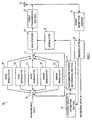
- FIG. 6 is a block diagram showing a configuration of a communication apparatus according to Embodiment 1 of the present invention.
- a communication terminal 100 mainly comprises antenna 101, radio reception section 102, demodulator 103, channel quality estimating section 104, transmission method determining section 105, switch 106, switch 107, control signal dividing section 108, BPSK modulator 109, QPSK modulator 110, 8PSK modulator 111, 16QAM modulator 112, 64QAM modulator 113, modulator 114, multiplexer 115 and radio transmission section 116.
- Radio reception section 102 receives a radio signal via antenna 101, carries out predetermined radio reception processing and outputs the received signal to demodulator 103.
- Demodulator 103 demodulates the received signal, separates the received data and the estimation value of the received signal quality which is estimated in reception quality estimating section 163 of the reception side as to be described later in FIG. 9, and outputs the result to channel quality estimating section 104 and other external sections.
- Channel quality estimating section 104 estimates the channel quality from the estimation value of the separated quality of reception signal and outputs the result to transmission method determining section 105 and control signal dividing section 108.
- Transmission method determining section 105 determines transmission method of a signal transmitted to communication partner from channel conditions and outputs the result to switch 106, switch 107 and control signal dividing section 108.
- an appropriate modulation method is selected among BPSK, QPSK, 8PSK, 16QAM and 64QAM modulation method as a transmission method.
- Channel conditions represent the state of communication channel such as channel quality, information of transmission power control, repetition information of a retransmission request, delay profile of the received signal, etc.
- Switch 106 outputs transmission data to either BPSK modulator 109, QPSK modulator 110, 8PSK modulator 111, 16QAM modulator 112, and 64QAM modulator 113 based on the transmission method determined in transmission method determining section 105.
- BPSK modulator 109 performs phase modulation on the transmission data so that 1 symbol corresponds to 2 bits (4 values) of information and outputs the result to switch 107.
- QPSK modulator 110 performs phase modulation on the transmission data so that 1 symbol corresponds to 2 bits (4 values) of information and outputs the result to switch 107.
- 8PSK modulator 111 performs phase modulation on the transmission data so that 1 symbol corresponds to 3 bits (8 values) of information and outputs the result to switch 107.
- 16QAM modulator 112 performs multi-level orthogonal amplitude modulation on the transmission data so that 1 symbol corresponds to 4 bits (16 values) of information and outputs the result to switch 107.
- 64QAM modulator 113 performs multi-level orthogonal amplitude modulation on the transmission data so that 1 symbol corresponds to 6 bits (64 values) of information and outputs the result to switch 107.
- Switch 107 outputs transmission data which is modulated in either BASK modulator 109, QPSK modulator 110, 8PSK modulator 111, 16QAM modulator 112, or 64QAM modulator 113 based on the transmission method determined in transmission method determining section 105 to multiplexer 115.
- Control signal dividing section 108 divides the transmission method information into high-speed control signal which is transmitted periodically and a low -speed control signal which is transmitted on demand rather than periodically. In addition, control signal dividing section 108 determines the combinations of low-speed control signal and high-speed control signal outputted from a tendency of communication quality, and outputs the result to modulator 114. Detailed description of the operation of control signal dividing section 108 will be described later.
- Modulator 114 modulates the high-speed control signal and low-speed control signal, and outputs the result to multiplexer 115.
- Multiplexer 115 multiplexes the modulated transmission data, high-speed control signal and low-speed control signal as a transmission signal and outputs it to radio transmission section 116.
- Radio transmission section 116 transmits a transmission signal subjected to predetermined radio processing via antenna 101.
- FIG. 7 is a table showing the correspondence relation between transmission method and control signal.
- the transmission method corresponds to two control signal.
- the transmission method shows the modulation technique
- two control signals show high-speed control signal which is transmitted periodically and low-speed control signal which is transmitted on demand rather than periodically.
- low-speed control signal uses “00” while high-speed control signal uses “0".
- low-speed control signal uses “00” while high-speed control signal uses “1” or low-speed control signal uses “01” while high-speed control signal uses “0”.
- 8PSK, 16QAM and 64QAM modulation method the used low-speed control signal and high-speed control signal are shown in FIG. 7.
- FIG. 8 shows a transmission example of the control signal.
- the horizontal axis represents time.
- a1, a2, a3 and a4 each represents the decision standard when transmission method determining section 105 determines the transmission method by which the signal is transmitted.
- communication apparatus 100 transmits the signal with BPSK.
- communication apparatus 100 transmits the signal with QPSK.
- communication apparatus 100 transmits the signal with 8PSK.
- communication apparatus 100 transmits the signal with 16QAM.
- communication apparatus 100 transmits the signal with 64QAM.
- transmission method determining section 105 determines the transmission of signal with QPSK.
- Control signal dividing section 108 outputs, based on the table in FIG. 7, low-speed control signal "00" and high-speed control signal "1" correspond to QPSK.
- transmission method determining section 105 determines the transmission of signal with BPSK.
- Control signal dividing section 108 outputs, based on the table in FIG. 7, low-speed control signal "00" and high-speed control signal "0" correspond to BPSK.
- control signal dividing section 108 Similar to time t2, at time t3 and t4, control signal dividing section 108 outputs, based on the table in FIG. 7, low-speed control signal "00" and high-speed control signal "0" correspond to BPSK.
- transmission method determining section 105 determines the transmission of signal with QPSK.
- Control signal dividing section 108 outputs, based on the table in FIG. 7, low-speed control signal "00" and high-speed control signal "1" correspond to QPSK.
- control signal dividing section 108 Similar to time t5, at time t6, control signal dividing section 108 outputs, based on the table in FIG. 7, low-speed control signal "00" and high-speed control signal "1" correspond to QPSK.
- transmission method determining section 105 determines the transmission of signal with QPSK.
- control signal dividing section 108 decides that the probability to update the modulation method from QPSK to 8PSK is higher than the probability to update the modulation method from QPSK to BPSK.
- control signal dividing section 108 outputs, based on the table in FIG. 7, low-speed control signal "01" corresponds to QPSK and 8PSK and high-speed control signal "0" corresponds to QPSK.
- transmission method determining section 105 determines the transmission of signal with 8PSK.
- Control signal dividing section 108 outputs, based on the table in FIG. 7, low-speed control signal "01" and high-speed control signal "1" correspond to 8PSK.
- control signal dividing section 108 Similar to time t8, at time t9, control signal dividing section 108 outputs, based on the table in FIG. 7, low-speed control signal "01" and high-speed control signal "1" correspond to 8PSK.
- transmission method determining section 105 determines the transmission of signal with 8PSK.
- control signal dividing section 108 decides that the probability to update the modulation method from 8PSK to 16QAM is higher than the probability to update the modulation method from 8PSK to QPSK.
- control signal dividing section 108 outputs, based on the table in FIG. 7, low-speed control signal "10" corresponds to 8PSK and 16QAM and high-speed control signal "0" corresponds to 8PSK.
- transmission method determining section 105 determines the transmission of signal with 16QAM.
- Control signal dividing section 108 outputs, based on the table in FIG. 7, low-speed control signal "10" and high-speed control signal "1" correspond to 16QAM.
- control signal dividing section 108 Similar to time t11, at time t12 and t13, control signal dividing section 108 outputs, based on the table in FIG. 7, low-speed control signal "10" and high-speed control signal "1" correspond to 16QAM.
- transmission method determining section 105 determines the transmission of signal with 16QAM.
- control signal dividing section 108 decides that the probability to update the modulation method from 16QAM to 64QAM is higher than the probability to update the modulation method from 16QAM to 8PSK.
- control signal dividing section 108 outputs, based on the table shown in FIG. 7, low-speed control signal "11" corresponds to 16QAM and 64QAM and high-speed control signal "0" corresponds to 16QAM.
- control signal dividing section 108 Similar to time t14, at time t15, control signal dividing section 108 outputs, based on the table in FIG. 7, low-speed control signal "11" and high-speed control signal "0" correspond to 16QAM.
- transmission method determining section 105 determines the transmission of signal with 64QAM.
- Control signal dividing section 108 outputs, based on the table in FIG. 7, low-speed control signal "11" and high-speed control signal "1" correspond to 64QAM.
- control signal dividing section 108 Similar to time t16, at time t17, control signal dividing section 108 outputs, based on the table in FIG. 7, low-speed control signal "11" and high-speed control signal "1" correspond to 64QAM.
- the communication apparatus of the present embodiment by dividing the transmission methods into a plurality of groups, deciding the group information in which the selected transmission method is included, transmits the group information when group information are updated, and transmits periodically the information which shows a specific transmission method among from groups, it is possible to reduce the size of a control signal transmitting periodically, and also possible to reduce the communication capacity of a control signal which indicates the transmission method.
- FIG. 9 is a block diagram showing a configuration of a communication apparatus according to the above-mentioned embodiment.
- a communication terminal 150 mainly comprises antenna 151, radio reception section 152, control signal separation section 153, high-speed/low-speed separation section 154, switch 155, storing section 156, addition section 157, switch 158, BPSK demodulator 159, QPSK demodulator 160, 8PSK demodulator 161, 16QAM demodulator 162, 64QAM demodulator 163, reception quality estimating section 164, modulator 165 and radio transmission section 166.
- Radio reception section 152 receives a radio signal via antenna 151 , carries out predetermined radio reception processing and outputs the obtained received signal to control signal separation section 153.
- Control signal separation section 153 extracts the control signal from the received signal and outputs it to high-speed/low-speed separation section 154. Control signal separation section 153 further outputs the received signal to switch 155.
- High-speed/low-speed separation section 154 divides the control signal to high-speed control signal and low-speed control signal, low-speed control signal is outputted to storing section 156 while high-speed signal is outputted to addition section 157.
- storing section 156 stores the low-speed control signal and outputs it to addition section 157.
- storing section 156 reflects it in the storing contents and outputs it to addition section 157.
- Addition section 157 combines low-speed control signal and high-speed control signal, and a selected information of the transmission method is generated then outputted to switch 155 and switch 158.
- addition section 157 adds low-speed control signal and high-speed control signal and generates the selected information of the transmission method.
- Switch 155 outputs transmission data to either BPSK demodulator 159, QPSK demodulator 160, 8PSK demodulator 161, 16QAM demodulator 162, and 64QAM demodulator 163 based on selected information of the transmission method generated in addition section 157.
- BPSK demodulator 159 demodulates the received signal using BPSK method and outputs the result to switch 158.
- QPSK demodulator 160 demodulates the received signal using QPSK method and outputs the result to switch 158.
- 8PSK demodulator 161 demodulates the received signal using 8PSK method and outputs the result to switch 158.
- 16QAM demodulator 162 demodulates the received signal using 16QAM method and outputs the result to switch 158.
- 64QAM demodulator 163 demodulates the received signal using 64QAM method and outputs the result to switch 158.
- Switch 158 selects the signal outputted from either BPSK demodulator 159, QPSK demodulator 160, 8PSK demodulator 161, 16QAM demodulator 162, and 64QAM demodulator 163 based on the selected information of the transmission method generated in addition section 157 and outputs the result to reception quality estimating section 164 and other external sections.
- Reception quality estimating section 164 estimates reception quality of the received data and outputs it to modulator 165.
- Modulator 165 modulates transmission data and reception quality information and outputs the result as a transmission signal to radio transmission section 166.
- Radio transmission section 166 transmits transmission signal via antenna 151 after carrying out predetermined radio processing.
- the communication apparatus of the present embodiment by receiving the group information in which the transmission method is included and information which specifies transmission method among the group and by specifying transmission method from an information which specifies group information, it is possible to reduce the size of control signal transmitting periodically, and also possible to reduce the communication capacity of control signal which indicates the transmission method.
- communication apparatus 100 of the present embodiment predicts the updating of a transmission method beforehand from communication quality of the receiving signal, but the present embodiment is not limited to this and it is possible to execute updating of transmission method along with prediction of the timing of transmission of low-speed control signal.
- low-speed control signal and high-speed control signal is not limited in particular.
- An example of a combination of low-speed control signal and high-speed control signal is shown below.
- FIG. 10 is a table showing the correspondence relation between transmission method and control signal.
- the transmission method corresponds to two control signals.
- transmission method shows the modulation technique
- the two control signals show high speed control signal which is transmitted periodically and low speed control signal which is transmitted on demand rather than periodically.
- low-speed control signal uses “0” while high-speed control signal uses “00".
- QPSK modulation technique low-speed control signal uses “0” while high-speed control signal uses “01” or low-speed control signal uses “1” while high-speed control signal uses “00”.
- 8PSK, 16QAM and 64QAM modulation method the used low-speed control signal and high-speed control signal are shown in FIG. 10.
- FIG. 11 shows transmission example of control signals .
- the horizontal axis represents time.
- a1, a2, a3 and a4 each represents decision standard when transmission method determining section 105 determines the transmission method by which a signal is transmitted. Operation of determining the modulation method from channel quality is the same as the operation of the above-mentioned embodiment.
- transmission method determining section 105 determines the transmission of signal with QPSK.
- Control signal dividing section 108 outputs, based on the table in FIG. 10, low-speed control signal "0" and high-speed control signal "01" correspond to QPSK.
- transmission method determining section 105 determines the transmission of signal with BPSK.
- Control signal dividing section 108 outputs, based on the table in FIG. 10, low-speed control signal "0" and high-speed control signal "00" correspond to BPSK.
- control signal dividing section 108 Similar to time t2, at time t3 and t4, control signal dividing section 108 outputs, based on the table in FIG. 10, low-speed control signal "0" and high-speed control signal "00" correspond to BPSK.
- control signal dividing section 108 Similar to time t1, at time t5, t6 and t7, control signal dividing section 108 outputs, based on the table in FIG. 10, low-speed control signal "0" and high-speed control signal "01" correspond to QPSK.
- transmission method determining section 105 determines the transmission of signal with 8PSK.
- Control signal dividing section 108 outputs, based on the table in FIG. 10, low-speed control signal "0" and high-speed control signal "10" correspond to 8PSK.
- control signal dividing section 108 Similar to time t8, at time t9, control signal dividing section 108 outputs, based on the table in FIG. 10, low-speed control signal "0" and high-speed control signal "10" correspond to 8PSK.
- transmission method determining section 105 determines the transmission of signal with 8PSK.
- control signal dividing section 108 decides that the probability to update the modulation method from 8PSK to 16QAM is higher than the probability to update the modulation method from 8PSK to QPSK.
- control signal dividing section 108 outputs, based on the table in FIG. 10, low-speed control signal "1" corresponds to 16QAM and 64QAM and high-speed control signal "01" corresponds to 8PSK.
- transmission method determining section 105 determines the transmission of signal with 16QAM.
- Control signal dividing section 108 outputs, based on the table in FIG. 10, low-speed control signal "1" and high-speed control signal "10" correspond to 16QAM.
- control signal dividing section 108 Similar to time t11, at time t12, t13, t14 and t15, control signal dividing section 108 outputs, based on the table in FIG. 10, low-speed control signal "1" and high-speed control signal "10" correspond to 16QAM.
- transmission method determining section 105 determines the transmission of signal with 64QAM.
- Control signal dividing section 108 outputs, based on the table in FIG. 10, low-speed control signal "1" and high-speed control signal "11" correspond to 64QAM.
- control signal dividing section 108 Similar to time t16, at time t17, control signal dividing section 108 outputs, based on the table in FIG. 10, low-speed control signal "1" and high-speed control signal "11" correspond to 16QAM.
- the communication apparatus of the present embodiment can reduce data capacity of the low-speed control signal.
- the kinds of the transmission method which can be covered by one low-speed control signal increase with increasing data capacity of high-speed control signal, transmission method can be updated without transmitting low-speed control signal again even in case when communication channel quality fluctuates suddenly.
- FIG. 12 is a block diagram showing a configuration of a communication apparatus according to Embodiment 2 of the present invention. However, the sections similar to those shown in FIG. 6 are assigned the same reference numerals and explanation thereof will be omitted.
- Communication apparatus 200 shown in FIG. 12 comprises control signal dividing section 201, and divides the transmission methods into a plurality of groups, determines the group information in which a selected transmission method is included, transmits only the group information when group information are updated, and does not transmit information which shows a specific transmission method among the group which is a different point from the communication apparatus shown in FIG. 6.
- Channel quality estimating section 104 estimates the channel quality from the quality estimation value of the reception signal separated in demodulator 103 and outputs the result to transmission method determining section 105 and control signal dividing section 201.
- Transmission method determining section 105 determines transmission method of a signal transmitting to communication partner using channel quality and outputs the result to switch 106, switch 107 and control signal dividing section 201.
- Control signal dividing section 201 divides the transmission method information into high-speed control signal which is transmitted periodically and low-speed control signal which is transmitted on demand rather than periodically, and outputs only low-speed control signal to modulator 114. Detailed description of the operation of control signal dividing section 201 will be described later.
- Modulator 114 modulates low-speed control signal, and outputs the result to multiplexer 115.
- FIG.13 shows a transmission example of control signal.
- the horizontal axis represents time.
- a1, a2, a3 and a4 each represents the decision standard when transmission method determining section 105 determines the transmission method by which the signal is transmitted. Operation of determining a modulation method from the channel quality is the same as the operation of the above-mentioned embodiment.
- transmissionmethod determining section 105 determines the transmission of signal with QPSK.
- Control signal dividing section 201 outputs, based on the table in FIG. 10, low-speed control signal "0" corresponds to QPSK.
- transmission method determining section 105 determines the transmission of signal with BPSK.
- Control signal dividing section 201 outputs, based on the table in FIG. 10, low-speed control signal "0" corresponds to BPSK.
- control signal dividing section 201 Similar to time t2, at time t3 and t4, control signal dividing section 201 outputs, based on the table in FIG. 10, low-speed control signal "0" corresponds to BPSK.
- control signal dividing section 201 Similar to time t1, at time t5, t6 and t7, control signal dividing section 201 outputs, based on the table in FIG. 10, low-speed control signal "0" corresponds to QPSK.
- transmission method determining section 105 determines the transmission of signal with 8PSK.
- Control signal dividing section 201 outputs, based on the table in FIG. 10, low-speed control signal "0" corresponds to 8PSK.
- control signal dividing section 201 outputs, based on the table in FIG. 10, low-speed control signal "0" corresponds to 8ASK.
- transmission method determining section 105 determines the transmission of signal with 8PSK.
- control signal dividing section 201 decides that the probability to update the modulation method from 8PSK to 16QAM is higher than the probability to update the modulation method from 8PSK to QPSK.
- control signal dividing section 201 outputs, based on the table in FIG. 10, low-speed control signal "1" corresponds to QPSK, 8PSK, 16QAM and 64QAM.
- transmission method determining section 105 determines the transmission of signal with 16QAM.
- Control signal dividing section 201 outputs, based on the table in FIG. 10, low-speed control signal "1" corresponds to 16QAM.
- control signal dividing section 201 Similar to time t11, at time t12, t13, t14 and t15, control signal dividing section 201 outputs, based on the table in FIG. 10, low-speed control signal "1" corresponds to 16QAM.
- transmission method determining section 105 determines the transmission of signal with 64QAM.
- Control signal dividing section 201 outputs, based on the table in FIG. 10, low-speed control signal "1" corresponds to 64QAM.
- control signal dividing section 201 Similar to time t16, at time t17, control signal dividing section 201 outputs, based on the table in FIG. 10, low-speed control signal "1" corresponds to 64QAM.
- the communication apparatus of the present embodiment by dividing the transmission methods into a plurality of groups, deciding the group information in which the selected transmission method is included and transmitting the group information when group information are updated, and by estimating the transmission method in the reception side by comparing between only symbol pattern of the plurality of the transmission methods shown by group information and symbol pattern of the received signal, it is possible to reduce the possibility of error in estimation as the number of candidates of the transmission method becomes small. Moreover, the amount of calculations required for estimation can also be decreased.
- FIG. 14 is a block diagram showing a configuration of a communication apparatus according to the aforementioned embodiment. However, the sections similar to those shown in FIG. 9 are assigned the same reference numerals and explanation thereof will be omitted.
- Communication apparatus 250 of FIG. 14 comprises control signal extraction section 251, switch 252, switch 253, switch 254, switch 255, BASK determining section 256, QPSK determining section 257, 8PSK determining section 258, 16QAM determining section 259, 64QAM determining section 260 and comparison section 261, a different point from the communication apparatus of FIG. 9 is that the demodulation is carried out after estimating the modulation technique of reception signal.
- Radio reception section 152 receives a radio signal through an antenna 151, carries out predetermined radio processing, and outputs the obtained received signal to switch 155, control signal extraction section 251, switch 252, switch 253, QPSK determining section 257, 8PSK determining section 258 and 16QAM determining section 259.
- Control signal extraction section 251 extracts low-speed control signal from the received signal and the transmission method which can be employed is determined, when the transmission method is either BPSK, QPSK, 8PSK or 16QAM, a circuit of switch 252 and switch 254 is connected while a circuit of switch 253 and switch 255 is disconnected.
- the transmission method is either QPSK, 8PSK, 16QAM or 64QAM, a circuit of switch 252 and switch 254 is disconnected while a circuit of switch 253 and switch 255 is connected.
- BPSK determining section 256 collects the phase distribution or amplitude distribution of a symbol pattern of received signal, determines whether these distributions coincide with distribution of BPSK symbol pattern and outputs the determination result to comparison section 261.
- QPSK determining section 257 collects the phase distribution or amplitude distribution of a symbol pattern of received signal, determines whether these distributions coincide with distribution of QPSK symbol pattern and outputs the determination result to comparison section 261.
- 8PSK determining section 258 collects the phase distribution or amplitude distribution of a symbol pattern of received signal, determines whether these distributions coincide with distribution of 8PSK symbol pattern and outputs the determination result to comparison section 261.
- 16QAM determining section 259 collects the phase distribution or amplitude distribution of a symbol pattern of received signal, determines whether these distributions coincide with distribution of 16QAM symbol pattern and outputs the determination result to comparison section 261.
- 64QAM determining section 260 collects the phase distribution or amplitude distribution of a symbol pattern of received signal, determines whether these distributions coincide with distribution of 64QAM symbol pattern and outputs the determination result to comparison section 261.
- Comparison section 261 compares the determination results outputted from BPSK determining section 256, QPSK determining section 257, 8PSK determining section 258, 16QAM determining section 259 and 64QAM determining section 260, and estimates the modulation method from the result in which the distribution of the received signal symbol pattern is mostly coincide with symbol pattern of each modulation technique. In addition, comparison section 261 carries out the switching between switch 155 and switch 158 from the estimation result of modulation method.
- the communication apparatus of the present embodiment by receiving the group information included the transmission method, estimating the transmission method by comparing between only the symbol pattern of a plurality of the transmission methods shown by group information and symbol pattern of the received signal, the possibility of error in estimation can be reduced as the number of candidates of estimated transmission method decreases. Moreover, the amount of calculations required for estimation can also be decreased.
- the error in estimation of 16QAM as 64QAM is eliminated in communication apparatus of reception side by transmission of low-speed control signal and specifying the modulation method as BPSK, QPSK, 8PSK and 16QAM.
- the error in estimation of QPSK as BPSK is eliminated in the communication apparatus of the receiving side by transmission of low-speed control signal and specifying the modulation method as QPSK, 8PSK, 16QAM and 64QAM.
- the communication apparatus of the present invention selects a modulation method among a plurality of modulation methods depending on channel quality, although the selection is carried out among a plurality of modulation techniques, but the selection is not limited to this and the selection method can be any method of which the transmission capacity of the communication is changed such as error correction method, spreading factor of CDMA, interleaving method, puncturing method, etc.
- the communication apparatus of the present invention can employ and compromise base station apparatus and communication terminal apparatus.
- the communication capacity of control signal which indicates the transmission method in a communication method selected among a plurality of transmission techniques can be reduced.
- the present invention is applicable to radio communication apparatus, base station apparatus and communication terminal apparatus.
Abstract
Description
- The present invention relates to a communication apparatus and a transmission technique selection method, in particular, relates to a communication apparatus and a transmission technique selection method that preferably used for an adaptive modulation to improve transmission efficiency of packet communication, etc.
- With the recent development of an Internet related art, it becomes possible to provide on the internet several kinds of services such as music on demand. In such a service, the transmission capacity of downlink channel is greatly increased. It is largely expected that high speed transmission in the downlink channel is to be achieved in order to realize services with large transmission capacity of the downlink channel. In addition, several technology developments are undergone on high speed transmission in downlink channel. As one technology of high speed transmission in downlink channel, a modulation method is adaptively updated in the transmission side, an adaptive modulation communication system carries out data transmission with a preferable efficiency.
- A conventional adaptive modulation communication system will be explained with reference to FIG. 1. FIG. 1 is a block diagram shows a conventional communication apparatus.
-
Communication apparatus 10 receives a radio signal inradio reception section 12 viaantenna 11. Predetermined radio reception processing are performed on the received signal inradio reception section 12. The radio reception processed signal is outputted todemodulator 13. The data is demodulated indemodulator 13, and it is separated into a reception data and estimation value of the reception signal estimated in receptionquality estimating section 61 of the receiving side to be described later using FIG. 5. Channelquality estimating section 14 estimates the channel quality from the estimation value of the separated quality of reception signal and outputs the result to transmissionmethod determining section 15. - Transmission
method determining section 15 determines transmission method of a signal transmitted to a communication partner from channel quality and outputs the result to switch 16,switch 17 andmodulator 18. Here, An appropriate modulation technique is chosen among BPSK (Binary Phase Shift Keying), QPSK, 8PSK, 16QAM (sixteen Quadrature Amplitude Modulation), 64QAM (sixty four Quadrature Amplitude Modulation) modulation as a transmission method. - Switch 16 outputs the transmission data to either
BPSK modulator 19,QPSK modulator 20,8PSK modulator 21,16QAM modulator 22, or 64QAM modulator 23 based on the transmission method determined in transmissionmethod determining section 15. -
BPSK modulator 19 performs phase modulation on the transmitting data so that 1 symbol corresponds to 1 bit (2 values) of information and outputs the result to switch 17.QPSK modulator 20 performs phase modulation on the transmitting data so that 1 symbol corresponds to 2 bits (4 values) of information and outputs the result to switch 17.8PSK modulator 21 performs phase modulation on the transmitting data so that 1 symbol corresponds to 3 bits (8 values) of information and outputs the result to switch 17. -
16QAM modulator 22 performs multi-level orthogonal amplitude modulation on the transmitting data so that 1 symbol corresponds to 4 bits (16 values) of information and outputs the result to switch 17. 64QAM modulator 23 performs multi-level orthogonal amplitude modulation on the transmitting data so that 1 symbol corresponds to 6 bits (64 values) of information and outputs the result to switch 17. - Switch 17 outputs the transmitting data which is modulated in either
BPSK modulator 19,QPSK modulator 20,8PSK modulator 21,16QAM modulator 22 or 64QAM modulator based on a transmission method determined in transmissionmethod determining section 15 tomultiplexer 24. -
Multiplexer 24 multiplexes the modulated transmitting data and the information of transmission method determined in transmissionmethod determining section 15 and outputs the result as a transmission signal toradio transmission section 25.Radio transmission section 25 transmits a transmission signal viaantenna 11 after carrying out predetermined radio processing. - The communication apparatus of the reception side will be explained below. FIG. 2 is a block diagram shows a conventional communication apparatus.
- The radio signal transmitted from the aforementioned communication apparatus is received through
antenna 51 and subjected to predetermined radio processing inradio reception section 52. The received signal outputted fromradio reception section 52 is separated into receiving signal and control signal in controlsignal separation section 53 and outputted to switch 54. Here, a control signal shows a transmission method selected in the transmission side. - Switch 54 outputs the receiving signal to either
BPSK demodulator 56,QPSK demodulator 57,8PSK demodulator 58,16QAM demodulator 59 or64QAM demodulator 60 according to the control signal. - BPSK
demodulator 56,QPSK demodulator 57,8PSK demodulator 58,16QAM demodulator 59 and64QAM demodulator 60 each demodulates the respective receiving signal and outputs the obtained received signal to switch 55. - Switch 55 outputs the receiving signal which is separated in control
signal separation section 53 after being demodulated by eitherBPSK demodulator 56,QPSK demodulator 57,8PSK demodulator 58,16QAM demodulator 59 and64QAM demodulator 60 to receptionquality estimating section 61 and other external sections. - Reception
quality estimating section 61 estimates reception quality of the receiving signal and outputs it tomodulator 62.Modulator 62 modulates the transmission data and reception quality information and outputs the result as a transmission signal toradio transmission section 63.Radio transmission section 63 transmits a transmission signal viaantenna 51 after carrying out predetermined radio processing. - Operation of the conventional communication apparatus will be explained below.
- FIG. 3 is a table showing the correspondence relation between transmission method and control signal. FIG. 3 shows the correspondence relation between transmission method and control signal. Here, transmission method shows the modulation technique and control signal which is periodically transmitted to a communication partner.
- When the signal is transmitted with BPSK modulation technique,
communication apparatus 10 uses "000" as a control signal. When the signal is transmitted with QPSK modulation technique,communication apparatus 10 uses "001" as a control signal. When the signal is transmitted with 8PSK modulation technique,communication apparatus 10 uses "010" as a control signal. When the signal is transmitted with 16QAM modulation technique,communication apparatus 10 uses "011" as a control signal. Finally, when the signal is transmitted with 64QAM modulation technique,communication apparatus 10 uses "100" as a control signal. - FIG. 4 shows a transmission example of the control signal. In FIG. 4, the horizontal axis represents time. In addition, a1, a2, a3 and a4 each represents decision standard when transmission
method determining section 15 determines the transmission method. - Here, when the channel quality is worse than a1,
communication apparatus 10 transmits the signal with BPSK. When the channel quality is more than a1 and worse than a2,communication apparatus 10 transmits the signal with QPSK. When the channel quality is more than a2 and worse than a3,communication apparatus 10 transmits the signal with 8PSK. When the channel quality is more than a3 and worse than a4,communication apparatus 10 transmits the signal with 16QAM. Finally, when the channel quality is more than a4,communication apparatus 10 transmits the signal with 64QAM. - At time t1, since the channel quality estimated by channel
quality estimating section 14 is more than a1 and worse than a2, transmissionmethod determining section 15 determines the transmission of signal with QPSK, and based on the table in FIG. 3, control signal "001" corresponds to conventional QPSK is outputted. - At the time t2, since the channel quality estimated by channel
quality estimating section 14 is worse than a1, transmissionmethod determining section 15 determines the transmission of signal with BPSK, and based on the table in FIG. 3, control signal "000" corresponds to BPSK is outputted. Similar to time t2, at time t3 and t4, transmissionmethod determining section 15, based on the table in FIG. 3, outputs control signal "000" corresponds to BPSK. - Similar to time t1, at time t5, t6 and t7, transmission
method determining section 15, based on the table in FIG. 3, outputs control signal "001" corresponds to QPSK. - At time t8, since the channel quality estimated by channel
quality estimating section 14 is more than a2 and worse than a3, transmissionmethod determining section 15 determines the transmission of signal with 8PSK, and based on the table in FIG. 3, outputs control signal "010" corresponds to 8PSK. Similar to time t8, at time t9 and t10, transmissionmethod determining section 15, based on the table in FIG. 3, outputs control signal "010" corresponds to 8PSK. - At time t11, since the channel quality estimated by channel
quality estimating section 14 is more than a3 and worse than a4, transmissionmethod determining section 15 determines the transmission of signal with 16QAM, and based on the table in FIG. 3, outputs control signal "011" corresponds to 16QAM. Similar to time t11, at time t12, t13, t14 and t15, transmissionmethod determining section 15, based on the table in FIG. 3, outputs control signal "011" corresponds to 16QAM. - At time t16, since the channel quality estimated by channel
quality estimating section 14 is more than a4, transmissionmethod determining section 15 determines the transmission of signal with 64QAM, and based on the table in FIG. 3, outputs control signal "100" corresponds to 64QAM. Similar to time t16, at time t17, transmissionmethod determining section 15, based on the table in FIG. 3, outputs control signal "100" corresponds to 64QAM. - Accordingly, in the aforementioned adaptive modulation communication system, the communication apparatus of transmission side carries out transmission by updating adaptively modulation technique and carries out transmission after multiplexing modulation technique information such as (number of Multi-Level, etc.) in the transmission signal. Thus, the communication apparatus of reception side can perform demodulation based on modulation technique information even if the modulation technique is adaptively updated.
- Moreover, there is a case where the information of the selected transmission method is not transmitted from the communication apparatus of transmission side, in such a case, the communication apparatus of reception side uses the so-called blind mode in which transmission method is estimated and then the received signal is demodulated.
- FIG. 5 is a block diagram showing a configuration of a conventional communication apparatus using a blind mode. However, the sections similar to those shown in FIG. 2 are assigned the same reference numerals and explanation thereof will be omitted.
- The communication apparatus of FIG. 5 comprises
BPSK determining section 70,QPSK determining section 71,8PSK determining section 72,16QAM determining section 73,64QAM determining section 74 andcomparison section 75, a different point from the communication apparatus of FIG. 2 is that the demodulation is carried out after estimating the modulation technique of the received signal. -
BPSK determining section 70 collects the phase distribution or amplitude distribution of a symbol pattern of the received signal, determines whether these distributions coincide with distribution of the BPSK symbol pattern and outputs the determination result tocomparison section 75.QPSK determining section 71 collects the phase distribution or amplitude distribution of a symbol pattern of the received signal, determines whether these distributions coincide with distribution of the QPSK symbol pattern and outputs the determination result tocomparison section 75. BASK determiningsection 72 collects the phase distribution or amplitude distribution of a symbol pattern of the received signal, determines whether these distributions coincide with distribution of the 8PSK symbol pattern and outputs the determination result tocomparison section 75. -
16QAM determining section 73 collects the phase distribution or amplitude distribution of a symbol pattern of the received signal, determines whether these distributions coincide with distribution of the 16QAM symbol pattern and outputs the determination result tocomparison section 75.64QAM determining section 74 collects the phase distribution or amplitude distribution of a symbol pattern of the received signal, determines whether these distributions coincide with distribution of the 64QAM symbol pattern and outputs the determination result tocomparison section 75. -
Comparison section 75 compares determination results outputted fromBPSK determining section 70,QPSK determining section 71,8PSK determining section 72,16QAM determining section 73 and64QAM determining section 74, and estimates the modulation method from the result in which the receiving signal symbol pattern is mostly coincide with a symbol pattern of each modulation technique. In addition,comparison section 75 carries out the switching betweenswitch 54 and switch 55 from the estimating result of modulation method. - However, because the selected information shows the signal transmitted with a transmission technique which can be selected among all transmission techniques in the conventional apparatus is transmitted to a communication partner, the kinds of information of the selected transmission method increases and the data capacity used for distinguishing the information of such selected transmission method becomes large, hence, there is a problem that the capacity of the transmitting data increases further in every transmission unit.
- Moreover, in blind mode in which a transmission method is estimated and reception processing is carried out in the reception side, there is a problem that a large number of calculations are required for estimation, or the error rate of estimation becomes large because there is a large number of candidates as an estimated transmission method.
- A first object of the present invention is to provide a communication apparatus and a transmission technique selection method to reduce the communication capacity of a control signal which indicates the transmission method in a communication method selected among a plurality of transmission techniques.
- Moreover, a second object of the present invention is to provide a communication apparatus and a transmission technique selection method to reduce the calculation required for estimation or to reduce the estimation error rate in blind mode.
- These objects can be achieved in a communication apparatus by adaptively updating the transmission method every transmission unit, dividing the information of the selected transmission method into a large frame information and a small information and transmitting only the large frame information when it is necessary, that is to say, a communication apparatus adaptively updates the transmission method every transmission unit, divides the transmission method into a plurality of groups, determines group information in which a selected transmission method is included, transmits the group information when they are updated, and transmits periodically the information which shows a specific transmission method among the group.
-
- FIG. 1 is a block diagram shows a conventional communication apparatus;
- FIG. 2 is a block diagram shows a conventional communication apparatus;
- FIG. 3 is a table showing the correspondence relation between transmission method and control signal;
- FIG.4 shows a transmission example of a control signal;
- FIG. 5 is a block diagram showing a configuration of a conventional communication apparatus using a blind mode;
- FIG. 6 is a block diagram showing a configuration of
a communication apparatus according to
Embodiment 1 of the present invention; - FIG. 7 is a table showing the correspondence relation between transmission method and control signal;
- FIG.8 shows a transmission example of a control signal;
- FIG. 9 is a block diagram showing a configuration of a communication apparatus according to the aforementioned embodiment;
- FIG. 10 is a table showing the correspondence relation between transmission method and control signal;
- FIG.11 shows a transmission example of a control signal;
- FIG. 12 is a block diagram showing a configuration of a communication apparatus according to Embodiment 2 of the present invention;
- FIG.13 shows a transmission example of a control signal; and
- FIG. 14 is a block diagram showing a configuration of a communication apparatus according to the aforementioned embodiment.
-
- Hereinafter, embodiments of the present invention will be specifically described with reference to the accompanying drawings.
- FIG. 6 is a block diagram showing a configuration of a communication apparatus according to
Embodiment 1 of the present invention; - In FIG. 6, a
communication terminal 100 mainly comprisesantenna 101,radio reception section 102,demodulator 103, channelquality estimating section 104, transmissionmethod determining section 105,switch 106,switch 107, controlsignal dividing section 108,BPSK modulator 109, QPSK modulator 110,8PSK modulator 111,16QAM modulator 112,64QAM modulator 113,modulator 114,multiplexer 115 andradio transmission section 116. -
Radio reception section 102 receives a radio signal viaantenna 101, carries out predetermined radio reception processing and outputs the received signal todemodulator 103.Demodulator 103 demodulates the received signal, separates the received data and the estimation value of the received signal quality which is estimated in receptionquality estimating section 163 of the reception side as to be described later in FIG. 9, and outputs the result to channelquality estimating section 104 and other external sections. Channelquality estimating section 104 estimates the channel quality from the estimation value of the separated quality of reception signal and outputs the result to transmissionmethod determining section 105 and controlsignal dividing section 108. - Transmission
method determining section 105 determines transmission method of a signal transmitted to communication partner from channel conditions and outputs the result to switch 106,switch 107 and controlsignal dividing section 108. Here, an appropriate modulation method is selected among BPSK, QPSK, 8PSK, 16QAM and 64QAM modulation method as a transmission method. - Channel conditions represent the state of communication channel such as channel quality, information of transmission power control, repetition information of a retransmission request, delay profile of the received signal, etc.
- Switch 106 outputs transmission data to either
BPSK modulator 109, QPSK modulator 110,8PSK modulator 111,16QAM modulator 112, and 64QAM modulator 113 based on the transmission method determined in transmissionmethod determining section 105. -
BPSK modulator 109 performs phase modulation on the transmission data so that 1 symbol corresponds to 2 bits (4 values) of information and outputs the result to switch 107. QPSK modulator 110 performs phase modulation on the transmission data so that 1 symbol corresponds to 2 bits (4 values) of information and outputs the result to switch 107.8PSK modulator 111 performs phase modulation on the transmission data so that 1 symbol corresponds to 3 bits (8 values) of information and outputs the result to switch 107. -
16QAM modulator 112 performs multi-level orthogonal amplitude modulation on the transmission data so that 1 symbol corresponds to 4 bits (16 values) of information and outputs the result to switch 107.64QAM modulator 113 performs multi-level orthogonal amplitude modulation on the transmission data so that 1 symbol corresponds to 6 bits (64 values) of information and outputs the result to switch 107. - Switch 107 outputs transmission data which is modulated in either BASK
modulator 109, QPSK modulator 110,8PSK modulator 111,16QAM modulator 112, or64QAM modulator 113 based on the transmission method determined in transmissionmethod determining section 105 tomultiplexer 115. - Control
signal dividing section 108 divides the transmission method information into high-speed control signal which is transmitted periodically and a low -speed control signal which is transmitted on demand rather than periodically. In addition, controlsignal dividing section 108 determines the combinations of low-speed control signal and high-speed control signal outputted from a tendency of communication quality, and outputs the result tomodulator 114. Detailed description of the operation of controlsignal dividing section 108 will be described later. -
Modulator 114 modulates the high-speed control signal and low-speed control signal, and outputs the result tomultiplexer 115. -
Multiplexer 115 multiplexes the modulated transmission data, high-speed control signal and low-speed control signal as a transmission signal and outputs it toradio transmission section 116.Radio transmission section 116 transmits a transmission signal subjected to predetermined radio processing viaantenna 101. - Operation of
communication apparatus 100 according to the present embodiment will be explained below. FIG. 7 is a table showing the correspondence relation between transmission method and control signal. In FIG. 7, the transmission method corresponds to two control signal. Here, the transmission method shows the modulation technique, and two control signals show high-speed control signal which is transmitted periodically and low-speed control signal which is transmitted on demand rather than periodically. - When the signal is transmitted with BPSK modulation technique, low-speed control signal uses "00" while high-speed control signal uses "0". When the signal is transmitted with QPSK modulation technique, low-speed control signal uses "00" while high-speed control signal uses "1" or low-speed control signal uses "01" while high-speed control signal uses "0". Similarly, when a signal is transmitted with either 8PSK, 16QAM and 64QAM modulation method, the used low-speed control signal and high-speed control signal are shown in FIG. 7.
- FIG. 8 shows a transmission example of the control signal. In FIG. 8, the horizontal axis represents time. Moreover, a1, a2, a3 and a4 each represents the decision standard when transmission
method determining section 105 determines the transmission method by which the signal is transmitted. - Here, when the channel quality is worse than a1,
communication apparatus 100 transmits the signal with BPSK. When the channel quality is more than a1 and worse than a2,communication apparatus 100 transmits the signal with QPSK. When the channel quality is more than a2 and worse than a3,communication apparatus 100 transmits the signal with 8PSK. When the channel quality is more than a3 and worse than a4,communication apparatus 100 transmits the signal with 16QAM. Finally, when the channel quality is more than a4,communication apparatus 100 transmits the signal with 64QAM. - At time t1, since the channel quality estimated by channel
quality estimating section 104 is more than a1 and worse than a2, transmissionmethod determining section 105 determines the transmission of signal with QPSK. Controlsignal dividing section 108 outputs, based on the table in FIG. 7, low-speed control signal "00" and high-speed control signal "1" correspond to QPSK. - At time t2, since the channel quality estimated by channel
quality estimating section 104 is worse than a1, transmissionmethod determining section 105 determines the transmission of signal with BPSK. Controlsignal dividing section 108 outputs, based on the table in FIG. 7, low-speed control signal "00" and high-speed control signal "0" correspond to BPSK. - Similar to time t2, at time t3 and t4, control
signal dividing section 108 outputs, based on the table in FIG. 7, low-speed control signal "00" and high-speed control signal "0" correspond to BPSK. - At time t5, since the channel quality estimated by channel
quality estimating section 104 is more than a1 and worse than a2, transmissionmethod determining section 105 determines the transmission of signal with QPSK. Controlsignal dividing section 108 outputs, based on the table in FIG. 7, low-speed control signal "00" and high-speed control signal "1" correspond to QPSK. - Similar to time t5, at time t6, control
signal dividing section 108 outputs, based on the table in FIG. 7, low-speed control signal "00" and high-speed control signal "1" correspond to QPSK. - At time t7, since the channel quality estimated by channel
quality estimating section 104 is more than a1 and worse than a2, transmissionmethod determining section 105 determines the transmission of signal with QPSK. With the improvement of the channel quality, controlsignal dividing section 108 decides that the probability to update the modulation method from QPSK to 8PSK is higher than the probability to update the modulation method from QPSK to BPSK. In addition, controlsignal dividing section 108 outputs, based on the table in FIG. 7, low-speed control signal "01" corresponds to QPSK and 8PSK and high-speed control signal "0" corresponds to QPSK. - At time t8, as the channel quality estimated by channel
quality estimating section 104 is more than a2 and worse than a3, transmissionmethod determining section 105 determines the transmission of signal with 8PSK. Controlsignal dividing section 108 outputs, based on the table in FIG. 7, low-speed control signal "01" and high-speed control signal "1" correspond to 8PSK. - Similar to time t8, at time t9, control
signal dividing section 108 outputs, based on the table in FIG. 7, low-speed control signal "01" and high-speed control signal "1" correspond to 8PSK. - At time t10, as the channel quality estimated by channel
quality estimating section 104 is more than a2 and worse than a3, transmissionmethod determining section 105 determines the transmission of signal with 8PSK. With the improvement of the channel quality, controlsignal dividing section 108 decides that the probability to update the modulation method from 8PSK to 16QAM is higher than the probability to update the modulation method from 8PSK to QPSK. In addition, controlsignal dividing section 108 outputs, based on the table in FIG. 7, low-speed control signal "10" corresponds to 8PSK and 16QAM and high-speed control signal "0" corresponds to 8PSK. - At time t11, because the channel quality estimated by channel
quality estimating section 104 is more than a3 and worse than a4, transmissionmethod determining section 105 determines the transmission of signal with 16QAM. Controlsignal dividing section 108 outputs, based on the table in FIG. 7, low-speed control signal "10" and high-speed control signal "1" correspond to 16QAM. - Similar to time t11, at time t12 and t13, control
signal dividing section 108 outputs, based on the table in FIG. 7, low-speed control signal "10" and high-speed control signal "1" correspond to 16QAM. - At time t14, as the channel quality estimated by channel
quality estimating section 104 is more than a3 and worse than a4, transmissionmethod determining section 105 determines the transmission of signal with 16QAM. With the improvement of the channel quality, controlsignal dividing section 108 decides that the probability to update the modulation method from 16QAM to 64QAM is higher than the probability to update the modulation method from 16QAM to 8PSK. In addition, controlsignal dividing section 108 outputs, based on the table shown in FIG. 7, low-speed control signal "11" corresponds to 16QAM and 64QAM and high-speed control signal "0" corresponds to 16QAM. - Similar to time t14, at time t15, control
signal dividing section 108 outputs, based on the table in FIG. 7, low-speed control signal "11" and high-speed control signal "0" correspond to 16QAM. - At time t16, as the channel quality estimated by channel
quality estimating section 104 is more than a4, transmissionmethod determining section 105 determines the transmission of signal with 64QAM. Controlsignal dividing section 108 outputs, based on the table in FIG. 7, low-speed control signal "11" and high-speed control signal "1" correspond to 64QAM. - Similar to time t16, at time t17, control
signal dividing section 108 outputs, based on the table in FIG. 7, low-speed control signal "11" and high-speed control signal "1" correspond to 64QAM. - According to the communication apparatus of the present embodiment, by dividing the transmission methods into a plurality of groups, deciding the group information in which the selected transmission method is included, transmits the group information when group information are updated, and transmits periodically the information which shows a specific transmission method among from groups, it is possible to reduce the size of a control signal transmitting periodically, and also possible to reduce the communication capacity of a control signal which indicates the transmission method.
- An explanation of a communication apparatus receiving the signal transmitted from
communication apparatus 100 will be given below. FIG. 9 is a block diagram showing a configuration of a communication apparatus according to the above-mentioned embodiment. - In FIG. 9, a
communication terminal 150 mainly comprisesantenna 151,radio reception section 152, controlsignal separation section 153, high-speed/low-speed separation section 154,switch 155, storingsection 156,addition section 157,switch 158,BPSK demodulator 159, QPSK demodulator 160,8PSK demodulator 161,16QAM demodulator 162,64QAM demodulator 163, receptionquality estimating section 164,modulator 165 andradio transmission section 166. -
Radio reception section 152 receives a radio signal viaantenna 151, carries out predetermined radio reception processing and outputs the obtained received signal to controlsignal separation section 153. - Control
signal separation section 153 extracts the control signal from the received signal and outputs it to high-speed/low-speed separation section 154. Controlsignal separation section 153 further outputs the received signal to switch 155. - High-speed/low-
speed separation section 154 divides the control signal to high-speed control signal and low-speed control signal, low-speed control signal is outputted to storingsection 156 while high-speed signal is outputted toaddition section 157. storingsection 156 stores the low-speed control signal and outputs it toaddition section 157. In addition, when a newly low-speed control signal is inputted, storingsection 156 reflects it in the storing contents and outputs it toaddition section 157. -
Addition section 157 combines low-speed control signal and high-speed control signal, and a selected information of the transmission method is generated then outputted to switch 155 andswitch 158. For example,addition section 157 adds low-speed control signal and high-speed control signal and generates the selected information of the transmission method. Switch 155 outputs transmission data to eitherBPSK demodulator 159, QPSK demodulator 160,8PSK demodulator 161,16QAM demodulator 162, and 64QAM demodulator 163 based on selected information of the transmission method generated inaddition section 157. -
BPSK demodulator 159 demodulates the received signal using BPSK method and outputs the result to switch 158. QPSK demodulator 160 demodulates the received signal using QPSK method and outputs the result to switch 158.8PSK demodulator 161 demodulates the received signal using 8PSK method and outputs the result to switch 158.16QAM demodulator 162 demodulates the received signal using 16QAM method and outputs the result to switch 158.64QAM demodulator 163 demodulates the received signal using 64QAM method and outputs the result to switch 158. -
Switch 158 selects the signal outputted from eitherBPSK demodulator 159, QPSK demodulator 160,8PSK demodulator 161,16QAM demodulator 162, and 64QAM demodulator 163 based on the selected information of the transmission method generated inaddition section 157 and outputs the result to receptionquality estimating section 164 and other external sections. - Reception
quality estimating section 164 estimates reception quality of the received data and outputs it tomodulator 165.Modulator 165 modulates transmission data and reception quality information and outputs the result as a transmission signal toradio transmission section 166.Radio transmission section 166 transmits transmission signal viaantenna 151 after carrying out predetermined radio processing. - According to the communication apparatus of the present embodiment, by receiving the group information in which the transmission method is included and information which specifies transmission method among the group and by specifying transmission method from an information which specifies group information, it is possible to reduce the size of control signal transmitting periodically, and also possible to reduce the communication capacity of control signal which indicates the transmission method.
- Moreover, although
communication apparatus 100 of the present embodiment predicts the updating of a transmission method beforehand from communication quality of the receiving signal, but the present embodiment is not limited to this and it is possible to execute updating of transmission method along with prediction of the timing of transmission of low-speed control signal. - In addition, the combination of low-speed control signal and high-speed control signal is not limited in particular. An example of a combination of low-speed control signal and high-speed control signal is shown below.
- FIG. 10 is a table showing the correspondence relation between transmission method and control signal. In FIG. 10, the transmission method corresponds to two control signals. Here, transmission method shows the modulation technique, and the two control signals show high speed control signal which is transmitted periodically and low speed control signal which is transmitted on demand rather than periodically.
- When a signal is transmitted using BPSK modulation technique, low-speed control signal uses "0" while high-speed control signal uses "00". When a signal is transmitted using QPSK modulation technique, low-speed control signal uses "0" while high-speed control signal uses "01" or low-speed control signal uses "1" while high-speed control signal uses "00". Similarly, when a signal is transmitted using either 8PSK, 16QAM and 64QAM modulation method, the used low-speed control signal and high-speed control signal are shown in FIG. 10.
- Operation of
communication apparatus 100 in the case when the above-mentioned two control signals are used will be explained. FIG. 11 shows transmission example of control signals . In FIG. 11, the horizontal axis represents time. Moreover, a1, a2, a3 and a4 each represents decision standard when transmissionmethod determining section 105 determines the transmission method by which a signal is transmitted. Operation of determining the modulation method from channel quality is the same as the operation of the above-mentioned embodiment. - At time t1, since the channel quality estimated by channel
quality estimating section 104 is more than a1 and worse than a2, transmissionmethod determining section 105 determines the transmission of signal with QPSK. Controlsignal dividing section 108 outputs, based on the table in FIG. 10, low-speed control signal "0" and high-speed control signal "01" correspond to QPSK. - At time t2, as the channel quality estimated by channel
quality estimating section 104 is less than a1, transmissionmethod determining section 105 determines the transmission of signal with BPSK. Controlsignal dividing section 108 outputs, based on the table in FIG. 10, low-speed control signal "0" and high-speed control signal "00" correspond to BPSK. - Similar to time t2, at time t3 and t4, control
signal dividing section 108 outputs, based on the table in FIG. 10, low-speed control signal "0" and high-speed control signal "00" correspond to BPSK. - Similar to time t1, at time t5, t6 and t7, control
signal dividing section 108 outputs, based on the table in FIG. 10, low-speed control signal "0" and high-speed control signal "01" correspond to QPSK. - At time t8, as the channel quality estimated by channel
quality estimating section 104 is more than a2 and worse than a3, transmissionmethod determining section 105 determines the transmission of signal with 8PSK. Controlsignal dividing section 108 outputs, based on the table in FIG. 10, low-speed control signal "0" and high-speed control signal "10" correspond to 8PSK. - Similar to time t8, at time t9, control
signal dividing section 108 outputs, based on the table in FIG. 10, low-speed control signal "0" and high-speed control signal "10" correspond to 8PSK. - At time t10, as the channel quality estimated by channel
quality estimating section 104 is more than a2 and worse than a3, transmissionmethod determining section 105 determines the transmission of signal with 8PSK. With the improvement of the channel quality, controlsignal dividing section 108 decides that the probability to update the modulation method from 8PSK to 16QAM is higher than the probability to update the modulation method from 8PSK to QPSK. In addition, controlsignal dividing section 108 outputs, based on the table in FIG. 10, low-speed control signal "1" corresponds to 16QAM and 64QAM and high-speed control signal "01" corresponds to 8PSK. - At time t11, as the channel quality estimated by channel
quality estimating section 104 is more than a3 and worse than a4, transmissionmethod determining section 105 determines the transmission of signal with 16QAM. Controlsignal dividing section 108 outputs, based on the table in FIG. 10, low-speed control signal "1" and high-speed control signal "10" correspond to 16QAM. - Similar to time t11, at time t12, t13, t14 and t15, control
signal dividing section 108 outputs, based on the table in FIG. 10, low-speed control signal "1" and high-speed control signal "10" correspond to 16QAM. - At time t16, since the channel quality estimated by channel
quality estimating section 104 is more than a4, transmissionmethod determining section 105 determines the transmission of signal with 64QAM. Controlsignal dividing section 108 outputs, based on the table in FIG. 10, low-speed control signal "1" and high-speed control signal "11" correspond to 64QAM. - Similar to time t16, at time t17, control
signal dividing section 108 outputs, based on the table in FIG. 10, low-speed control signal "1" and high-speed control signal "11" correspond to 16QAM. - Accordingly, the communication apparatus of the present embodiment can reduce data capacity of the low-speed control signal. In such a case, because the kinds of the transmission method which can be covered by one low-speed control signal increase with increasing data capacity of high-speed control signal, transmission method can be updated without transmitting low-speed control signal again even in case when communication channel quality fluctuates suddenly.
- FIG. 12 is a block diagram showing a configuration of a communication apparatus according to Embodiment 2 of the present invention. However, the sections similar to those shown in FIG. 6 are assigned the same reference numerals and explanation thereof will be omitted.
- Communication apparatus 200 shown in FIG. 12 comprises control
signal dividing section 201, and divides the transmission methods into a plurality of groups, determines the group information in which a selected transmission method is included, transmits only the group information when group information are updated, and does not transmit information which shows a specific transmission method among the group which is a different point from the communication apparatus shown in FIG. 6. - Channel
quality estimating section 104 estimates the channel quality from the quality estimation value of the reception signal separated indemodulator 103 and outputs the result to transmissionmethod determining section 105 and controlsignal dividing section 201. Transmissionmethod determining section 105 determines transmission method of a signal transmitting to communication partner using channel quality and outputs the result to switch 106,switch 107 and controlsignal dividing section 201. - Control
signal dividing section 201 divides the transmission method information into high-speed control signal which is transmitted periodically and low-speed control signal which is transmitted on demand rather than periodically, and outputs only low-speed control signal tomodulator 114. Detailed description of the operation of controlsignal dividing section 201 will be described later. -
Modulator 114 modulates low-speed control signal, and outputs the result tomultiplexer 115. - Operation of communication apparatus 200 according to the present embodiment will be explained below. FIG.13 shows a transmission example of control signal. In FIG. 13, the horizontal axis represents time. Moreover, a1, a2, a3 and a4 each represents the decision standard when transmission
method determining section 105 determines the transmission method by which the signal is transmitted. Operation of determining a modulation method from the channel quality is the same as the operation of the above-mentioned embodiment. - At time t1, since the channel quality estimated by channel
quality estimating section 104 is more than a1 and worse than a2,transmissionmethod determining section 105 determines the transmission of signal with QPSK. Controlsignal dividing section 201 outputs, based on the table in FIG. 10, low-speed control signal "0" corresponds to QPSK. - At time t2, because the channel quality estimated by channel
quality estimating section 104 is less than a1, transmissionmethod determining section 105 determines the transmission of signal with BPSK. Controlsignal dividing section 201 outputs, based on the table in FIG. 10, low-speed control signal "0" corresponds to BPSK. - Similar to time t2, at time t3 and t4, control
signal dividing section 201 outputs, based on the table in FIG. 10, low-speed control signal "0" corresponds to BPSK. - Similar to time t1, at time t5, t6 and t7, control
signal dividing section 201 outputs, based on the table in FIG. 10, low-speed control signal "0" corresponds to QPSK. - At time t8, as the channel quality estimated by channel
quality estimating section 104 is more than a2 and worse than a3, transmissionmethod determining section 105 determines the transmission of signal with 8PSK. Controlsignal dividing section 201 outputs, based on the table in FIG. 10, low-speed control signal "0" corresponds to 8PSK. - Similar to time t8, at time t9, control
signal dividing section 201 outputs, based on the table in FIG. 10, low-speed control signal "0" corresponds to 8ASK. - At
time 110, as the channel quality estimated by channelquality estimating section 104 is more than a2 and worse than a3, transmissionmethod determining section 105 determines the transmission of signal with 8PSK. With the improvement of the channel quality, controlsignal dividing section 201 decides that the probability to update the modulation method from 8PSK to 16QAM is higher than the probability to update the modulation method from 8PSK to QPSK. In addition, controlsignal dividing section 201 outputs, based on the table in FIG. 10, low-speed control signal "1" corresponds to QPSK, 8PSK, 16QAM and 64QAM. - At time t11, because the channel quality estimated by channel
quality estimating section 104 is more than a3 and worse than a4, transmissionmethod determining section 105 determines the transmission of signal with 16QAM. Controlsignal dividing section 201 outputs, based on the table in FIG. 10, low-speed control signal "1" corresponds to 16QAM. - Similar to time t11, at time t12, t13, t14 and t15, control
signal dividing section 201 outputs, based on the table in FIG. 10, low-speed control signal "1" corresponds to 16QAM. - At time t16, as the channel quality estimated by channel
quality estimating section 104 is more than a4, transmissionmethod determining section 105 determines the transmission of signal with 64QAM. Controlsignal dividing section 201 outputs, based on the table in FIG. 10, low-speed control signal "1" corresponds to 64QAM. - Similar to time t16, at time t17, control
signal dividing section 201 outputs, based on the table in FIG. 10, low-speed control signal "1" corresponds to 64QAM. - According to the communication apparatus of the present embodiment, by dividing the transmission methods into a plurality of groups, deciding the group information in which the selected transmission method is included and transmitting the group information when group information are updated, and by estimating the transmission method in the reception side by comparing between only symbol pattern of the plurality of the transmission methods shown by group information and symbol pattern of the received signal, it is possible to reduce the possibility of error in estimation as the number of candidates of the transmission method becomes small. Moreover, the amount of calculations required for estimation can also be decreased.
- An explanation of a communication apparatus receiving radio signal transmitted from communication apparatus 200 will be given below. FIG. 14 is a block diagram showing a configuration of a communication apparatus according to the aforementioned embodiment. However, the sections similar to those shown in FIG. 9 are assigned the same reference numerals and explanation thereof will be omitted.
-
Communication apparatus 250 of FIG. 14 comprises controlsignal extraction section 251,switch 252,switch 253,switch 254,switch 255, BASK determiningsection 256,QPSK determining section 257,8PSK determining section 258,16QAM determining section 259,64QAM determining section 260 andcomparison section 261, a different point from the communication apparatus of FIG. 9 is that the demodulation is carried out after estimating the modulation technique of reception signal. -
Radio reception section 152 receives a radio signal through anantenna 151, carries out predetermined radio processing, and outputs the obtained received signal to switch 155, controlsignal extraction section 251,switch 252,switch 253,QPSK determining section 257,8PSK determining section 258 and16QAM determining section 259. - Control
signal extraction section 251 extracts low-speed control signal from the received signal and the transmission method which can be employed is determined, when the transmission method is either BPSK, QPSK, 8PSK or 16QAM, a circuit ofswitch 252 and switch 254 is connected while a circuit ofswitch 253 and switch 255 is disconnected. - Moreover, when the transmission method is either QPSK, 8PSK, 16QAM or 64QAM, a circuit of
switch 252 and switch 254 is disconnected while a circuit ofswitch 253 and switch 255 is connected. -
BPSK determining section 256 collects the phase distribution or amplitude distribution of a symbol pattern of received signal, determines whether these distributions coincide with distribution of BPSK symbol pattern and outputs the determination result tocomparison section 261.QPSK determining section 257 collects the phase distribution or amplitude distribution of a symbol pattern of received signal, determines whether these distributions coincide with distribution of QPSK symbol pattern and outputs the determination result tocomparison section 261.8PSK determining section 258 collects the phase distribution or amplitude distribution of a symbol pattern of received signal, determines whether these distributions coincide with distribution of 8PSK symbol pattern and outputs the determination result tocomparison section 261. -
16QAM determining section 259 collects the phase distribution or amplitude distribution of a symbol pattern of received signal, determines whether these distributions coincide with distribution of 16QAM symbol pattern and outputs the determination result tocomparison section 261.64QAM determining section 260 collects the phase distribution or amplitude distribution of a symbol pattern of received signal, determines whether these distributions coincide with distribution of 64QAM symbol pattern and outputs the determination result tocomparison section 261. -
Comparison section 261 compares the determination results outputted fromBPSK determining section 256,QPSK determining section 257,8PSK determining section 258,16QAM determining section 259 and64QAM determining section 260, and estimates the modulation method from the result in which the distribution of the received signal symbol pattern is mostly coincide with symbol pattern of each modulation technique. In addition,comparison section 261 carries out the switching betweenswitch 155 and switch 158 from the estimation result of modulation method. - According to the communication apparatus of the present embodiment, by receiving the group information included the transmission method, estimating the transmission method by comparing between only the symbol pattern of a plurality of the transmission methods shown by group information and symbol pattern of the received signal, the possibility of error in estimation can be reduced as the number of candidates of estimated transmission method decreases. Moreover, the amount of calculations required for estimation can also be decreased.
- For example, when either of BPSK, QPSK, 8PSK, 16QAM and 64QAM is used for signal transmission, the error in estimation of 16QAM as 64QAM is eliminated in communication apparatus of reception side by transmission of low-speed control signal and specifying the modulation method as BPSK, QPSK, 8PSK and 16QAM.
- Moreover, the error in estimation of QPSK as BPSK is eliminated in the communication apparatus of the receiving side by transmission of low-speed control signal and specifying the modulation method as QPSK, 8PSK, 16QAM and 64QAM.
- In addition, the communication apparatus of the present invention selects a modulation method among a plurality of modulation methods depending on channel quality, although the selection is carried out among a plurality of modulation techniques, but the selection is not limited to this and the selection method can be any method of which the transmission capacity of the communication is changed such as error correction method, spreading factor of CDMA, interleaving method, puncturing method, etc.
- In addition, the communication apparatus of the present invention can employ and compromise base station apparatus and communication terminal apparatus.
- As it is clear from the above explanation and according to the communication apparatus and transmission technique selection method of the present invention, the communication capacity of control signal which indicates the transmission method in a communication method selected among a plurality of transmission techniques can be reduced.
- The present application is based on the Japanese Patent Application No. 2001-051622 filed on Feb. 27, 2001, entire content of which is expressly incorporated by reference herein.
- The present invention is applicable to radio communication apparatus, base station apparatus and communication terminal apparatus.
Claims (10)
- A communication apparatus, in which a communication is carried out by selecting one transmission method among a plurality of transmission methods, comprising:transmission method determining section which selects a transmission method from a plurality of transmission methods used for signal transmission;control signal dividing section which generates a range information which shows a candidate of a transmission method selected among selection information that show a selected transmission method, and specific information that is used to specify the selection information from the range information;transmission method which transmits the range information.
- The communication apparatus according to claim 1, wherein said transmission section transmits the range information when the range information is updated.
- The communication apparatus according to claim 1, wherein said transmission section transmits periodically the specific information.
- The communication apparatus according to claim 1, wherein said transmission method determining section selects the transmission method that is used for signal transmission from channel conditions, and said control signal dividing section generates range information from the channel quality information.
- A communication apparatus comprising:control signal separation section which extracts a range information and a specific information from a receiving signal;separation section which separates the extracted range information and specific information;storing section which stores the range information;recovering section which determines the transmission method from the range information and specific information and recovers received data from the received signal using the determined transmission method.
- A communication apparatus comprising:control signal extraction section which extracts a range information from a reception signal;transmission method estimating section which estimates transmission method of the reception signal from transmission methods specified by the range information;recovering section which recovers the reception signal using the estimated transmission method.
- A communication apparatus comprising a base station apparatus, wherein said communication apparatus, in which a communication is carried out by selecting one transmission method among a plurality of transmission methods, comprising:transmission method determining section which selects a transmission method from a plurality of transmission methods;control signal dividing section which generates a range information that shows a candidate of a transmission method selected among selection information show a selected transmission method, and a specific information to specify the selection information from the range information;transmission section which transmits the range information.
- A communication apparatus comprising a communication terminal apparatus, wherein said communication apparatus, in which a communication is carried out by selecting one transmission method among a plurality of transmission methods, comprising:transmission method determining section which selects a transmission method used for signal transmission from a plurality of transmission methods;control signal dividing section which generates a range information shows a candidate of a transmission method selected among selection information that show a selected transmission method and a specific information to specify the selection information from the range information;transmission section which transmits said range information.
- A transmission technique selection method in a communication method by which a communication is carried out by selecting one transmission method among a plurality of transmission method,
wherein said transmission technique selection method in transmission side comprising:wherein said transmission technique selection method in reception side comprising:step of selection a transmission method used for signal transmission from a plurality of transmission methods;step of generating a range information shows a candidate of a transmission method selected among a selection information which show a selected transmission method; andstep of transmitting the range information, andstep of extracting the range information from a reception signal;step of estimating transmission method of the reception signal from transmission methods specified by the range information; andstep of recovering the reception signal with the estimated transmission method. - A transmission technique selection method in a communication method by which a communication is carried out by selecting one transmission method among a plurality of transmission method,
wherein said transmission technique selection method in transmission side comprising:step of selection a transmission method used for signal transmission from a plurality of transmission methods;step of generating a range information shows a candidate of a transmission method selected among selection information that show a selected transmission method and a specific information to specify the selection information from the range information;step of transmitting the range information;step of transmitting periodically the specific information;step of extracting the range information and the specific information from reception signal;step of separating the extracted range information and specific informationstep of storing the range information;step of determining transmission method from the range information and specific information; andstep of recovering received data from reception signal with the determined transmission method.
Applications Claiming Priority (3)
| Application Number | Priority Date | Filing Date | Title |
|---|---|---|---|
| JP2001051622 | 2001-02-27 | ||
| JP2001051622A JP3589992B2 (en) | 2001-02-27 | 2001-02-27 | Communication device and transmission method selection method |
| PCT/JP2002/001519 WO2002069591A1 (en) | 2001-02-27 | 2002-02-21 | Communication device and transmission mode selecting method |
Publications (3)
| Publication Number | Publication Date |
|---|---|
| EP1274208A1 true EP1274208A1 (en) | 2003-01-08 |
| EP1274208A4 EP1274208A4 (en) | 2009-12-02 |
| EP1274208B1 EP1274208B1 (en) | 2012-01-04 |
Family
ID=18912372
Family Applications (1)
| Application Number | Title | Priority Date | Filing Date |
|---|---|---|---|
| EP02700655A Expired - Lifetime EP1274208B1 (en) | 2001-02-27 | 2002-02-21 | Communication device and transmission mode selecting method |
Country Status (6)
| Country | Link |
|---|---|
| US (1) | US6965639B2 (en) |
| EP (1) | EP1274208B1 (en) |
| JP (1) | JP3589992B2 (en) |
| KR (1) | KR20020093964A (en) |
| CN (1) | CN1198430C (en) |
| WO (1) | WO2002069591A1 (en) |
Cited By (8)
| Publication number | Priority date | Publication date | Assignee | Title |
|---|---|---|---|---|
| WO2003101062A1 (en) * | 2002-05-20 | 2003-12-04 | Qualcomm Incorporated | Method and apparatus for a multiple modulation transmitter |
| EP1398929A1 (en) * | 2002-09-13 | 2004-03-17 | Siemens Aktiengesellschaft | Method and Apparatus used on the receiver side for determining the modulation used on the transmitter side in a communication system with adaptive modulation |
| EP1406405A1 (en) * | 2002-10-04 | 2004-04-07 | Alcatel | System and method for adaptive modulation based on channel estimates and capacity requirements |
| EP2066052A2 (en) | 2007-11-29 | 2009-06-03 | Samsung Electronics Co., Ltd. | Broadcast receiving apparatus and method for receiving hierarchically modulated broadcast signals |
| WO2010081552A1 (en) * | 2009-01-15 | 2010-07-22 | Nokia Siemens Networks Gmbh & Co. Kg | Transmitting a first and a second channel quality information between two network elements |
| CN102013937A (en) * | 2009-09-07 | 2011-04-13 | 普天信息技术研究院有限公司 | Channel quality estimation method and transmission method of E-UCCH (Enhanced-Uplink Control Channel) |
| WO2013066399A1 (en) * | 2011-11-04 | 2013-05-10 | Qualcomm Incorporated | Method and apparatus for interference cancellation by a user equipment using blind detection |
| US9723496B2 (en) | 2011-11-04 | 2017-08-01 | Qualcomm Incorporated | Method and apparatus for interference cancellation by a user equipment using blind detection |
Families Citing this family (26)
| Publication number | Priority date | Publication date | Assignee | Title |
|---|---|---|---|---|
| JP3973506B2 (en) * | 2002-07-19 | 2007-09-12 | 三洋電機株式会社 | Wireless receiving apparatus, wireless receiving method, and wireless receiving program |
| JP4353774B2 (en) * | 2002-12-04 | 2009-10-28 | パナソニック株式会社 | Data transmission method and data reception method, and transmission apparatus and reception apparatus using them |
| JP4506979B2 (en) * | 2003-05-27 | 2010-07-21 | 日本電気株式会社 | Data communication apparatus for selecting modulation scheme with appropriate threshold in adaptive modulation |
| JP4182345B2 (en) | 2003-06-26 | 2008-11-19 | 日本電気株式会社 | Interference cancellation unit and multi-user interference canceller |
| US20050041805A1 (en) * | 2003-08-04 | 2005-02-24 | Lowell Rosen | Miniaturized holographic communications apparatus and methods |
| US7418047B2 (en) * | 2004-02-25 | 2008-08-26 | Matsushita Electric Industrial Co., Ltd. | Communication apparatus using a plurality of modulation schemes and transmission apparatus composing such communication apparatus |
| JP4077800B2 (en) * | 2004-02-27 | 2008-04-23 | 日本電信電話株式会社 | Radio channel quality judgment method and radio access system |
| JP2006135674A (en) * | 2004-11-05 | 2006-05-25 | Ntt Docomo Inc | Receiver for mobile communication, transmitter for mobile communication, reception method for mobile communication, and transmission method for mobile communication |
| US7423964B2 (en) * | 2004-11-18 | 2008-09-09 | International Business Machines Corporation | Apparatus and method to set the signaling rate of a network disposed within an information storage and retrieval system |
| US8743708B1 (en) | 2005-08-01 | 2014-06-03 | Rockwell Collins, Inc. | Device and method supporting cognitive, dynamic media access control |
| US7583611B1 (en) * | 2005-08-01 | 2009-09-01 | Rockwell Collins, Inc. | System and method to support communication between non-cognitive radios and cognitive radios |
| JP4818271B2 (en) * | 2005-08-18 | 2011-11-16 | パナソニック株式会社 | Wireless communication terminal apparatus and CQI selection method |
| JP4760333B2 (en) * | 2005-11-28 | 2011-08-31 | セイコーエプソン株式会社 | Wireless communication apparatus and wireless communication method |
| JP4684146B2 (en) * | 2006-03-27 | 2011-05-18 | 京セラ株式会社 | Mobile station equipment |
| WO2007148784A1 (en) * | 2006-06-23 | 2007-12-27 | Nec Corporation | Wireless communication apparatus and method for switching modulation schemes thereof |
| US20080207258A1 (en) * | 2007-02-26 | 2008-08-28 | Broadcom Corporation, A California Corporation | Multimode transmitter with digital up conversion and methods for use therewith |
| US7990922B2 (en) * | 2007-11-09 | 2011-08-02 | Samsung Electronics Co., Ltd. | Method and apparatus for transmitting information of device in wireless personal area network |
| US8213949B1 (en) * | 2008-11-26 | 2012-07-03 | Clearwire Ip Holdings Llc | Adjustable modulation for overhead information in wireless communication networks |
| JP4668315B2 (en) * | 2008-12-02 | 2011-04-13 | フェリカネットワークス株式会社 | Information processing apparatus, communication control method, and program |
| KR100998095B1 (en) | 2009-12-30 | 2010-12-03 | 엘아이지넥스원 주식회사 | Apparatus for controlling target, and system for controlling target with the said apparatus |
| JP5590150B2 (en) * | 2010-12-27 | 2014-09-17 | 日本電気株式会社 | STP routing control system applied to radio communication apparatus having AMR function |
| JP6003386B2 (en) * | 2012-08-16 | 2016-10-05 | 日本電気株式会社 | Wireless communication apparatus, wireless frame generation method, and communication system |
| CN105103511B (en) | 2013-04-12 | 2019-02-15 | 太阳专利托管公司 | Sending method |
| KR102183442B1 (en) * | 2013-04-18 | 2020-11-26 | 삼성전자주식회사 | Method and apparatus for transmitting and receiving signals using multiple modulation and coding schemes in a wireless communication system |
| US10050878B2 (en) * | 2015-05-07 | 2018-08-14 | Texas Instruments Incorporated | Network communication system with node energy reduction packet protocol |
| GB201611856D0 (en) * | 2016-07-07 | 2016-08-24 | Univ Surrey | Transmitting and receiving data in a wireless communication network |
Citations (3)
| Publication number | Priority date | Publication date | Assignee | Title |
|---|---|---|---|---|
| US5577087A (en) * | 1991-10-31 | 1996-11-19 | Nec Corporation | Variable modulation communication method and system |
| EP0944200A2 (en) * | 1998-03-19 | 1999-09-22 | Fujitsu Limited | Adaptive modulation method and apparatus |
| WO2000041318A1 (en) * | 1999-01-06 | 2000-07-13 | University Of Southampton | Burst-by-burst adaptive single-carrier data transmission |
Family Cites Families (8)
| Publication number | Priority date | Publication date | Assignee | Title |
|---|---|---|---|---|
| US5950124A (en) * | 1995-09-06 | 1999-09-07 | Telxon Corporation | Cellular communication system with dynamically modified data transmission parameters |
| JPH09186635A (en) * | 1995-12-29 | 1997-07-15 | Kokusai Electric Co Ltd | Equalizer |
| JPH09307541A (en) | 1996-05-15 | 1997-11-28 | Kokusai Electric Co Ltd | Frame synchronization circuit |
| JP3324941B2 (en) * | 1996-09-11 | 2002-09-17 | 株式会社日立国際電気 | Transceiver with variable modulation parameter adaptive modulation scheme |
| US5983101A (en) * | 1996-11-26 | 1999-11-09 | Telefonaktiebolaget Lm Ericsson | Point to multipoint radio access system |
| JP3066483B2 (en) | 1997-03-04 | 2000-07-17 | 郵政省通信総合研究所長 | Digital mobile radio communication method |
| CN1257382A (en) * | 1998-07-24 | 2000-06-21 | 休斯电子公司 | Frame formatting for aerial interface |
| JP2001268019A (en) | 2000-03-23 | 2001-09-28 | Hitachi Kokusai Electric Inc | Digital mobile communication system |
-
2001
- 2001-02-27 JP JP2001051622A patent/JP3589992B2/en not_active Expired - Fee Related
-
2002
- 2002-02-21 KR KR1020027014432A patent/KR20020093964A/en not_active Application Discontinuation
- 2002-02-21 WO PCT/JP2002/001519 patent/WO2002069591A1/en not_active Application Discontinuation
- 2002-02-21 CN CNB028004582A patent/CN1198430C/en not_active Expired - Fee Related
- 2002-02-21 US US10/239,923 patent/US6965639B2/en not_active Expired - Fee Related
- 2002-02-21 EP EP02700655A patent/EP1274208B1/en not_active Expired - Lifetime
Patent Citations (3)
| Publication number | Priority date | Publication date | Assignee | Title |
|---|---|---|---|---|
| US5577087A (en) * | 1991-10-31 | 1996-11-19 | Nec Corporation | Variable modulation communication method and system |
| EP0944200A2 (en) * | 1998-03-19 | 1999-09-22 | Fujitsu Limited | Adaptive modulation method and apparatus |
| WO2000041318A1 (en) * | 1999-01-06 | 2000-07-13 | University Of Southampton | Burst-by-burst adaptive single-carrier data transmission |
Non-Patent Citations (1)
| Title |
|---|
| See also references of WO02069591A1 * |
Cited By (11)
| Publication number | Priority date | Publication date | Assignee | Title |
|---|---|---|---|---|
| WO2003101062A1 (en) * | 2002-05-20 | 2003-12-04 | Qualcomm Incorporated | Method and apparatus for a multiple modulation transmitter |
| US6906996B2 (en) | 2002-05-20 | 2005-06-14 | Qualcomm Inc | Multiple modulation wireless transmitter |
| EP1398929A1 (en) * | 2002-09-13 | 2004-03-17 | Siemens Aktiengesellschaft | Method and Apparatus used on the receiver side for determining the modulation used on the transmitter side in a communication system with adaptive modulation |
| EP1406405A1 (en) * | 2002-10-04 | 2004-04-07 | Alcatel | System and method for adaptive modulation based on channel estimates and capacity requirements |
| EP2066052A2 (en) | 2007-11-29 | 2009-06-03 | Samsung Electronics Co., Ltd. | Broadcast receiving apparatus and method for receiving hierarchically modulated broadcast signals |
| WO2010081552A1 (en) * | 2009-01-15 | 2010-07-22 | Nokia Siemens Networks Gmbh & Co. Kg | Transmitting a first and a second channel quality information between two network elements |
| US10128977B2 (en) | 2009-01-15 | 2018-11-13 | Fraunhofer-Gesellschaft Zur Foerderung Der Angewandten Forschung E.V. | Transmitting a first and a second channel quality information between two network elements |
| CN102013937A (en) * | 2009-09-07 | 2011-04-13 | 普天信息技术研究院有限公司 | Channel quality estimation method and transmission method of E-UCCH (Enhanced-Uplink Control Channel) |
| CN102013937B (en) * | 2009-09-07 | 2013-01-02 | 普天信息技术研究院有限公司 | Channel quality estimation method and transmission method of E-UCCH (Enhanced-Uplink Control Channel) |
| WO2013066399A1 (en) * | 2011-11-04 | 2013-05-10 | Qualcomm Incorporated | Method and apparatus for interference cancellation by a user equipment using blind detection |
| US9723496B2 (en) | 2011-11-04 | 2017-08-01 | Qualcomm Incorporated | Method and apparatus for interference cancellation by a user equipment using blind detection |
Also Published As
| Publication number | Publication date |
|---|---|
| EP1274208B1 (en) | 2012-01-04 |
| US6965639B2 (en) | 2005-11-15 |
| EP1274208A4 (en) | 2009-12-02 |
| WO2002069591A1 (en) | 2002-09-06 |
| US20030053549A1 (en) | 2003-03-20 |
| CN1457583A (en) | 2003-11-19 |
| JP2002261851A (en) | 2002-09-13 |
| KR20020093964A (en) | 2002-12-16 |
| JP3589992B2 (en) | 2004-11-17 |
| CN1198430C (en) | 2005-04-20 |
Similar Documents
| Publication | Publication Date | Title |
|---|---|---|
| US6965639B2 (en) | Communication apparatus and transmission technique selection method | |
| JP4713632B2 (en) | Transmission method and apparatus combining pulse modulation and hierarchical modulation | |
| EP1024622B1 (en) | Method and system for selecting a coding scheme | |
| US5771226A (en) | Data rate detector for terminal station receiver | |
| KR100738823B1 (en) | Modulation method for transmitter | |
| RU2622853C2 (en) | Two-stage alarm system for data flow transfer | |
| EP1204256B1 (en) | Adaptive modulation communication system | |
| US8204144B2 (en) | Wireless communication system, apparatus and method thereof | |
| KR20020032620A (en) | Communication terminal apparatus, base station apparatus, and communication method | |
| JPH11178050A (en) | Control information transmission method, transmitter, and transmitter-receiver | |
| KR100759235B1 (en) | Demodulation method for receiver | |
| EP1626552B1 (en) | Multiple independent pathway communications | |
| JP2928224B1 (en) | Antenna switching diversity receiving apparatus and receiving method | |
| JP2000261398A (en) | Communication equipment | |
| US7274759B2 (en) | Antenna switching based on a preamble MSE metric | |
| US7469124B1 (en) | Rate adaptive satellite communications | |
| EP2040406A2 (en) | Data communication device and data communication method | |
| EP1383290A1 (en) | Radio receiving apparatus, method for determining modulation scheme, and method for determining coding scheme | |
| US20080049873A1 (en) | System and method to perform DC compensation on a radio frequency burst in a cellular wireless network | |
| JP4376658B2 (en) | Base station apparatus, mobile terminal and mobile communication system | |
| US20050031054A1 (en) | Digital communication device and digital communication system | |
| US7333550B2 (en) | Bit processing method for adaptive multirate modulation | |
| JP2003319007A (en) | Base station equipment, and packet transmission method | |
| KR20030092095A (en) | Method, apparatus and system for synchronization in radio communication systems | |
| Tang et al. | Notice of Violation of IEEE Publication Principles: Adaptive modulation for fading channels |
Legal Events
| Date | Code | Title | Description |
|---|---|---|---|
| PUAI | Public reference made under article 153(3) epc to a published international application that has entered the european phase |
Free format text: ORIGINAL CODE: 0009012 |
|
| 17P | Request for examination filed |
Effective date: 20021024 |
|
| AK | Designated contracting states |
Kind code of ref document: A1 Designated state(s): AT BE CH CY DE DK ES FI FR GB GR IE IT LI LU MC NL PT SE TR |
|
| AX | Request for extension of the european patent |
Free format text: AL;LT;LV;MK;RO;SI |
|
| RAP1 | Party data changed (applicant data changed or rights of an application transferred) |
Owner name: PANASONIC CORPORATION |
|
| A4 | Supplementary search report drawn up and despatched |
Effective date: 20091029 |
|
| RIC1 | Information provided on ipc code assigned before grant |
Ipc: H04L 1/00 20060101AFI20091023BHEP Ipc: H04L 27/00 20060101ALI20091023BHEP Ipc: H04L 27/38 20060101ALI20091023BHEP |
|
| 17Q | First examination report despatched |
Effective date: 20100712 |
|
| GRAP | Despatch of communication of intention to grant a patent |
Free format text: ORIGINAL CODE: EPIDOSNIGR1 |
|
| GRAS | Grant fee paid |
Free format text: ORIGINAL CODE: EPIDOSNIGR3 |
|
| GRAA | (expected) grant |
Free format text: ORIGINAL CODE: 0009210 |
|
| AK | Designated contracting states |
Kind code of ref document: B1 Designated state(s): DE FR GB |
|
| REG | Reference to a national code |
Ref country code: GB Ref legal event code: FG4D |
|
| REG | Reference to a national code |
Ref country code: DE Ref legal event code: R096 Ref document number: 60241887 Country of ref document: DE Effective date: 20120308 |
|
| PLBE | No opposition filed within time limit |
Free format text: ORIGINAL CODE: 0009261 |
|
| STAA | Information on the status of an ep patent application or granted ep patent |
Free format text: STATUS: NO OPPOSITION FILED WITHIN TIME LIMIT |
|
| 26N | No opposition filed |
Effective date: 20121005 |
|
| REG | Reference to a national code |
Ref country code: DE Ref legal event code: R097 Ref document number: 60241887 Country of ref document: DE Effective date: 20121005 |
|
| REG | Reference to a national code |
Ref country code: GB Ref legal event code: 732E Free format text: REGISTERED BETWEEN 20140612 AND 20140618 |
|
| REG | Reference to a national code |
Ref country code: DE Ref legal event code: R082 Ref document number: 60241887 Country of ref document: DE Representative=s name: GRUENECKER, KINKELDEY, STOCKMAIR & SCHWANHAEUS, DE |
|
| REG | Reference to a national code |
Ref country code: DE Ref legal event code: R081 Ref document number: 60241887 Country of ref document: DE Owner name: PANASONIC INTELLECTUAL PROPERTY CORPORATION OF, US Free format text: FORMER OWNER: PANASONIC CORP., KADOMA-SHI, OSAKA, JP Effective date: 20140711 Ref country code: DE Ref legal event code: R081 Ref document number: 60241887 Country of ref document: DE Owner name: PANASONIC INTELLECTUAL PROPERTY CORPORATION OF, US Free format text: FORMER OWNER: MATSUSHITA ELECTRIC INDUSTRIAL CO., LTD., KADOMA-SHI, OSAKA, JP Effective date: 20120116 Ref country code: DE Ref legal event code: R082 Ref document number: 60241887 Country of ref document: DE Representative=s name: GRUENECKER, KINKELDEY, STOCKMAIR & SCHWANHAEUS, DE Effective date: 20140711 Ref country code: DE Ref legal event code: R081 Ref document number: 60241887 Country of ref document: DE Owner name: PANASONIC INTELLECTUAL PROPERTY CORPORATION OF, US Free format text: FORMER OWNER: PANASONIC CORPORATION, KADOMA-SHI, OSAKA, JP Effective date: 20140711 Ref country code: DE Ref legal event code: R082 Ref document number: 60241887 Country of ref document: DE Representative=s name: GRUENECKER PATENT- UND RECHTSANWAELTE PARTG MB, DE Effective date: 20140711 |
|
| REG | Reference to a national code |
Ref country code: FR Ref legal event code: TP Owner name: PANASONIC INTELLECTUAL PROPERTY CORPORATION OF, US Effective date: 20140722 |
|
| REG | Reference to a national code |
Ref country code: FR Ref legal event code: PLFP Year of fee payment: 14 |
|
| PGFP | Annual fee paid to national office [announced via postgrant information from national office to epo] |
Ref country code: DE Payment date: 20150219 Year of fee payment: 14 |
|
| PGFP | Annual fee paid to national office [announced via postgrant information from national office to epo] |
Ref country code: FR Payment date: 20150219 Year of fee payment: 14 Ref country code: GB Payment date: 20150218 Year of fee payment: 14 |
|
| REG | Reference to a national code |
Ref country code: DE Ref legal event code: R119 Ref document number: 60241887 Country of ref document: DE |
|
| GBPC | Gb: european patent ceased through non-payment of renewal fee |
Effective date: 20160221 |
|
| REG | Reference to a national code |
Ref country code: FR Ref legal event code: ST Effective date: 20161028 |
|
| PG25 | Lapsed in a contracting state [announced via postgrant information from national office to epo] |
Ref country code: GB Free format text: LAPSE BECAUSE OF NON-PAYMENT OF DUE FEES Effective date: 20160221 Ref country code: FR Free format text: LAPSE BECAUSE OF NON-PAYMENT OF DUE FEES Effective date: 20160229 Ref country code: DE Free format text: LAPSE BECAUSE OF NON-PAYMENT OF DUE FEES Effective date: 20160901 |