EP1274144A2 - Wicking structures for water and /or fuel management in fuel cells - Google Patents
Wicking structures for water and /or fuel management in fuel cells Download PDFInfo
- Publication number
- EP1274144A2 EP1274144A2 EP02014413A EP02014413A EP1274144A2 EP 1274144 A2 EP1274144 A2 EP 1274144A2 EP 02014413 A EP02014413 A EP 02014413A EP 02014413 A EP02014413 A EP 02014413A EP 1274144 A2 EP1274144 A2 EP 1274144A2
- Authority
- EP
- European Patent Office
- Prior art keywords
- anode
- cathode
- liquid fuel
- fuel cell
- wicking structure
- Prior art date
- Legal status (The legal status is an assumption and is not a legal conclusion. Google has not performed a legal analysis and makes no representation as to the accuracy of the status listed.)
- Withdrawn
Links
- 239000000446 fuel Substances 0.000 title claims abstract description 350
- XLYOFNOQVPJJNP-UHFFFAOYSA-N water Substances O XLYOFNOQVPJJNP-UHFFFAOYSA-N 0.000 title claims abstract description 127
- 239000007788 liquid Substances 0.000 claims abstract description 312
- 239000000463 material Substances 0.000 claims abstract description 167
- 239000000835 fiber Substances 0.000 claims abstract description 121
- 239000006260 foam Substances 0.000 claims abstract description 91
- 229920005830 Polyurethane Foam Polymers 0.000 claims description 111
- 239000011496 polyurethane foam Substances 0.000 claims description 111
- CURLTUGMZLYLDI-UHFFFAOYSA-N Carbon dioxide Chemical compound O=C=O CURLTUGMZLYLDI-UHFFFAOYSA-N 0.000 claims description 81
- -1 polyethylene Polymers 0.000 claims description 79
- 239000012528 membrane Substances 0.000 claims description 66
- 230000001590 oxidative effect Effects 0.000 claims description 53
- 239000007787 solid Substances 0.000 claims description 53
- 239000005518 polymer electrolyte Substances 0.000 claims description 51
- 239000001569 carbon dioxide Substances 0.000 claims description 42
- 229910002092 carbon dioxide Inorganic materials 0.000 claims description 42
- 229920000728 polyester Polymers 0.000 claims description 39
- 239000000203 mixture Substances 0.000 claims description 37
- 239000012530 fluid Substances 0.000 claims description 36
- 238000004891 communication Methods 0.000 claims description 35
- 238000006243 chemical reaction Methods 0.000 claims description 31
- 239000004743 Polypropylene Substances 0.000 claims description 30
- 229920002678 cellulose Polymers 0.000 claims description 30
- 239000001913 cellulose Substances 0.000 claims description 30
- 229920001155 polypropylene Polymers 0.000 claims description 30
- 239000007800 oxidant agent Substances 0.000 claims description 29
- 239000004698 Polyethylene Substances 0.000 claims description 28
- 229920002239 polyacrylonitrile Polymers 0.000 claims description 28
- 229920000573 polyethylene Polymers 0.000 claims description 28
- 229910052751 metal Inorganic materials 0.000 claims description 27
- 239000002184 metal Substances 0.000 claims description 27
- 239000003054 catalyst Substances 0.000 claims description 26
- 239000004952 Polyamide Substances 0.000 claims description 25
- 229920002647 polyamide Polymers 0.000 claims description 25
- 239000011148 porous material Substances 0.000 claims description 25
- 239000004677 Nylon Substances 0.000 claims description 17
- 229920001778 nylon Polymers 0.000 claims description 17
- 229920000139 polyethylene terephthalate Polymers 0.000 claims description 16
- 239000005020 polyethylene terephthalate Substances 0.000 claims description 16
- 229920000877 Melamine resin Polymers 0.000 claims description 15
- JDSHMPZPIAZGSV-UHFFFAOYSA-N melamine Chemical compound NC1=NC(N)=NC(N)=N1 JDSHMPZPIAZGSV-UHFFFAOYSA-N 0.000 claims description 15
- 239000011888 foil Substances 0.000 claims description 13
- OKTJSMMVPCPJKN-UHFFFAOYSA-N Carbon Chemical compound [C] OKTJSMMVPCPJKN-UHFFFAOYSA-N 0.000 claims description 11
- 229910052799 carbon Inorganic materials 0.000 claims description 11
- 238000000576 coating method Methods 0.000 claims description 11
- 239000011248 coating agent Substances 0.000 claims description 10
- 150000002739 metals Chemical class 0.000 claims description 6
- 210000002268 wool Anatomy 0.000 claims description 4
- 239000000126 substance Substances 0.000 claims description 3
- 239000012799 electrically-conductive coating Substances 0.000 claims 2
- OKKJLVBELUTLKV-UHFFFAOYSA-N Methanol Chemical compound OC OKKJLVBELUTLKV-UHFFFAOYSA-N 0.000 abstract description 109
- 238000011084 recovery Methods 0.000 abstract description 5
- 239000002131 composite material Substances 0.000 abstract description 3
- 239000000047 product Substances 0.000 description 24
- 238000010586 diagram Methods 0.000 description 20
- 230000006835 compression Effects 0.000 description 15
- 238000007906 compression Methods 0.000 description 15
- QVGXLLKOCUKJST-UHFFFAOYSA-N atomic oxygen Chemical compound [O] QVGXLLKOCUKJST-UHFFFAOYSA-N 0.000 description 11
- 238000000034 method Methods 0.000 description 11
- 239000001301 oxygen Substances 0.000 description 9
- 229910052760 oxygen Inorganic materials 0.000 description 9
- PXHVJJICTQNCMI-UHFFFAOYSA-N Nickel Chemical compound [Ni] PXHVJJICTQNCMI-UHFFFAOYSA-N 0.000 description 6
- 238000009950 felting Methods 0.000 description 6
- 239000007789 gas Substances 0.000 description 6
- LFQSCWFLJHTTHZ-UHFFFAOYSA-N Ethanol Chemical compound CCO LFQSCWFLJHTTHZ-UHFFFAOYSA-N 0.000 description 5
- 229920000642 polymer Polymers 0.000 description 5
- 239000000376 reactant Substances 0.000 description 5
- 238000004064 recycling Methods 0.000 description 5
- 239000004721 Polyphenylene oxide Substances 0.000 description 4
- 239000002253 acid Substances 0.000 description 4
- 239000001257 hydrogen Substances 0.000 description 4
- 229910052739 hydrogen Inorganic materials 0.000 description 4
- 238000007726 management method Methods 0.000 description 4
- BDAGIHXWWSANSR-UHFFFAOYSA-N methanoic acid Natural products OC=O BDAGIHXWWSANSR-UHFFFAOYSA-N 0.000 description 4
- 229920000570 polyether Polymers 0.000 description 4
- 239000000243 solution Substances 0.000 description 4
- PYOKUURKVVELLB-UHFFFAOYSA-N trimethyl orthoformate Chemical compound COC(OC)OC PYOKUURKVVELLB-UHFFFAOYSA-N 0.000 description 4
- LYCAIKOWRPUZTN-UHFFFAOYSA-N Ethylene glycol Chemical compound OCCO LYCAIKOWRPUZTN-UHFFFAOYSA-N 0.000 description 3
- 239000007864 aqueous solution Substances 0.000 description 3
- 239000003792 electrolyte Substances 0.000 description 3
- 229910052759 nickel Inorganic materials 0.000 description 3
- 239000011800 void material Substances 0.000 description 3
- OSWFIVFLDKOXQC-UHFFFAOYSA-N 4-(3-methoxyphenyl)aniline Chemical compound COC1=CC=CC(C=2C=CC(N)=CC=2)=C1 OSWFIVFLDKOXQC-UHFFFAOYSA-N 0.000 description 2
- OAKJQQAXSVQMHS-UHFFFAOYSA-N Hydrazine Chemical compound NN OAKJQQAXSVQMHS-UHFFFAOYSA-N 0.000 description 2
- 229920000557 Nafion® Polymers 0.000 description 2
- 229920001247 Reticulated foam Polymers 0.000 description 2
- VYPSYNLAJGMNEJ-UHFFFAOYSA-N Silicium dioxide Chemical compound O=[Si]=O VYPSYNLAJGMNEJ-UHFFFAOYSA-N 0.000 description 2
- 150000007513 acids Chemical class 0.000 description 2
- 230000008901 benefit Effects 0.000 description 2
- 238000009835 boiling Methods 0.000 description 2
- 239000004020 conductor Substances 0.000 description 2
- 238000005520 cutting process Methods 0.000 description 2
- NKDDWNXOKDWJAK-UHFFFAOYSA-N dimethoxymethane Chemical compound COCOC NKDDWNXOKDWJAK-UHFFFAOYSA-N 0.000 description 2
- 238000007772 electroless plating Methods 0.000 description 2
- 235000019253 formic acid Nutrition 0.000 description 2
- GPRLSGONYQIRFK-UHFFFAOYSA-N hydron Chemical group [H+] GPRLSGONYQIRFK-UHFFFAOYSA-N 0.000 description 2
- 238000004519 manufacturing process Methods 0.000 description 2
- 229920000620 organic polymer Polymers 0.000 description 2
- 230000035699 permeability Effects 0.000 description 2
- BASFCYQUMIYNBI-UHFFFAOYSA-N platinum Chemical compound [Pt] BASFCYQUMIYNBI-UHFFFAOYSA-N 0.000 description 2
- 238000005086 pumping Methods 0.000 description 2
- 230000036647 reaction Effects 0.000 description 2
- 238000007740 vapor deposition Methods 0.000 description 2
- VYZAMTAEIAYCRO-UHFFFAOYSA-N Chromium Chemical compound [Cr] VYZAMTAEIAYCRO-UHFFFAOYSA-N 0.000 description 1
- RYGMFSIKBFXOCR-UHFFFAOYSA-N Copper Chemical compound [Cu] RYGMFSIKBFXOCR-UHFFFAOYSA-N 0.000 description 1
- MYMOFIZGZYHOMD-UHFFFAOYSA-N Dioxygen Chemical compound O=O MYMOFIZGZYHOMD-UHFFFAOYSA-N 0.000 description 1
- UFHFLCQGNIYNRP-UHFFFAOYSA-N Hydrogen Chemical compound [H][H] UFHFLCQGNIYNRP-UHFFFAOYSA-N 0.000 description 1
- MHAJPDPJQMAIIY-UHFFFAOYSA-N Hydrogen peroxide Chemical compound OO MHAJPDPJQMAIIY-UHFFFAOYSA-N 0.000 description 1
- BQCADISMDOOEFD-UHFFFAOYSA-N Silver Chemical compound [Ag] BQCADISMDOOEFD-UHFFFAOYSA-N 0.000 description 1
- RTAQQCXQSZGOHL-UHFFFAOYSA-N Titanium Chemical compound [Ti] RTAQQCXQSZGOHL-UHFFFAOYSA-N 0.000 description 1
- HCHKCACWOHOZIP-UHFFFAOYSA-N Zinc Chemical compound [Zn] HCHKCACWOHOZIP-UHFFFAOYSA-N 0.000 description 1
- 230000001154 acute effect Effects 0.000 description 1
- 239000000853 adhesive Substances 0.000 description 1
- 230000001070 adhesive effect Effects 0.000 description 1
- 230000002411 adverse Effects 0.000 description 1
- 150000001298 alcohols Chemical class 0.000 description 1
- 229910045601 alloy Inorganic materials 0.000 description 1
- 239000000956 alloy Substances 0.000 description 1
- PNEYBMLMFCGWSK-UHFFFAOYSA-N aluminium oxide Inorganic materials [O-2].[O-2].[O-2].[Al+3].[Al+3] PNEYBMLMFCGWSK-UHFFFAOYSA-N 0.000 description 1
- 239000003575 carbonaceous material Substances 0.000 description 1
- 230000001413 cellular effect Effects 0.000 description 1
- 239000007795 chemical reaction product Substances 0.000 description 1
- 229910017052 cobalt Inorganic materials 0.000 description 1
- 239000010941 cobalt Substances 0.000 description 1
- GUTLYIVDDKVIGB-UHFFFAOYSA-N cobalt atom Chemical compound [Co] GUTLYIVDDKVIGB-UHFFFAOYSA-N 0.000 description 1
- 229920001940 conductive polymer Polymers 0.000 description 1
- 238000010276 construction Methods 0.000 description 1
- 229910052802 copper Inorganic materials 0.000 description 1
- 239000010949 copper Substances 0.000 description 1
- 238000002788 crimping Methods 0.000 description 1
- 230000007423 decrease Effects 0.000 description 1
- 230000008021 deposition Effects 0.000 description 1
- 238000009792 diffusion process Methods 0.000 description 1
- 239000003085 diluting agent Substances 0.000 description 1
- 229910001882 dioxygen Inorganic materials 0.000 description 1
- 230000005611 electricity Effects 0.000 description 1
- 239000010411 electrocatalyst Substances 0.000 description 1
- 238000003487 electrochemical reaction Methods 0.000 description 1
- 239000004744 fabric Substances 0.000 description 1
- 239000006261 foam material Substances 0.000 description 1
- PCHJSUWPFVWCPO-UHFFFAOYSA-N gold Chemical compound [Au] PCHJSUWPFVWCPO-UHFFFAOYSA-N 0.000 description 1
- 229910052737 gold Inorganic materials 0.000 description 1
- 239000010931 gold Substances 0.000 description 1
- 230000005484 gravity Effects 0.000 description 1
- 238000010438 heat treatment Methods 0.000 description 1
- 230000003116 impacting effect Effects 0.000 description 1
- 238000011065 in-situ storage Methods 0.000 description 1
- 229910001026 inconel Inorganic materials 0.000 description 1
- 230000001788 irregular Effects 0.000 description 1
- 230000004048 modification Effects 0.000 description 1
- 238000012986 modification Methods 0.000 description 1
- 238000007254 oxidation reaction Methods 0.000 description 1
- 239000003973 paint Substances 0.000 description 1
- 238000010422 painting Methods 0.000 description 1
- 239000002245 particle Substances 0.000 description 1
- 230000000149 penetrating effect Effects 0.000 description 1
- 238000002047 photoemission electron microscopy Methods 0.000 description 1
- 229910052697 platinum Inorganic materials 0.000 description 1
- 229920001483 poly(ethyl methacrylate) polymer Polymers 0.000 description 1
- 239000000843 powder Substances 0.000 description 1
- 238000004080 punching Methods 0.000 description 1
- 229910052703 rhodium Inorganic materials 0.000 description 1
- 239000010948 rhodium Substances 0.000 description 1
- MHOVAHRLVXNVSD-UHFFFAOYSA-N rhodium atom Chemical compound [Rh] MHOVAHRLVXNVSD-UHFFFAOYSA-N 0.000 description 1
- 238000000926 separation method Methods 0.000 description 1
- 239000000377 silicon dioxide Substances 0.000 description 1
- 229910052709 silver Inorganic materials 0.000 description 1
- 239000004332 silver Substances 0.000 description 1
- 229910001220 stainless steel Inorganic materials 0.000 description 1
- 239000010935 stainless steel Substances 0.000 description 1
- 239000000758 substrate Substances 0.000 description 1
- 239000000725 suspension Substances 0.000 description 1
- 238000003856 thermoforming Methods 0.000 description 1
- 239000010936 titanium Substances 0.000 description 1
- 229910052719 titanium Inorganic materials 0.000 description 1
- WFKWXMTUELFFGS-UHFFFAOYSA-N tungsten Chemical compound [W] WFKWXMTUELFFGS-UHFFFAOYSA-N 0.000 description 1
- 229910052721 tungsten Inorganic materials 0.000 description 1
- 239000010937 tungsten Substances 0.000 description 1
- 238000003466 welding Methods 0.000 description 1
- 229910052725 zinc Inorganic materials 0.000 description 1
- 239000011701 zinc Substances 0.000 description 1
Images


Classifications
-
- H—ELECTRICITY
- H01—ELECTRIC ELEMENTS
- H01M—PROCESSES OR MEANS, e.g. BATTERIES, FOR THE DIRECT CONVERSION OF CHEMICAL ENERGY INTO ELECTRICAL ENERGY
- H01M8/00—Fuel cells; Manufacture thereof
- H01M8/04—Auxiliary arrangements, e.g. for control of pressure or for circulation of fluids
- H01M8/04082—Arrangements for control of reactant parameters, e.g. pressure or concentration
- H01M8/04089—Arrangements for control of reactant parameters, e.g. pressure or concentration of gaseous reactants
- H01M8/04119—Arrangements for control of reactant parameters, e.g. pressure or concentration of gaseous reactants with simultaneous supply or evacuation of electrolyte; Humidifying or dehumidifying
- H01M8/04156—Arrangements for control of reactant parameters, e.g. pressure or concentration of gaseous reactants with simultaneous supply or evacuation of electrolyte; Humidifying or dehumidifying with product water removal
- H01M8/04171—Arrangements for control of reactant parameters, e.g. pressure or concentration of gaseous reactants with simultaneous supply or evacuation of electrolyte; Humidifying or dehumidifying with product water removal using adsorbents, wicks or hydrophilic material
-
- H—ELECTRICITY
- H01—ELECTRIC ELEMENTS
- H01M—PROCESSES OR MEANS, e.g. BATTERIES, FOR THE DIRECT CONVERSION OF CHEMICAL ENERGY INTO ELECTRICAL ENERGY
- H01M8/00—Fuel cells; Manufacture thereof
- H01M8/04—Auxiliary arrangements, e.g. for control of pressure or for circulation of fluids
-
- H—ELECTRICITY
- H01—ELECTRIC ELEMENTS
- H01M—PROCESSES OR MEANS, e.g. BATTERIES, FOR THE DIRECT CONVERSION OF CHEMICAL ENERGY INTO ELECTRICAL ENERGY
- H01M8/00—Fuel cells; Manufacture thereof
- H01M8/04—Auxiliary arrangements, e.g. for control of pressure or for circulation of fluids
- H01M8/04291—Arrangements for managing water in solid electrolyte fuel cell systems
-
- H—ELECTRICITY
- H01—ELECTRIC ELEMENTS
- H01M—PROCESSES OR MEANS, e.g. BATTERIES, FOR THE DIRECT CONVERSION OF CHEMICAL ENERGY INTO ELECTRICAL ENERGY
- H01M8/00—Fuel cells; Manufacture thereof
- H01M8/10—Fuel cells with solid electrolytes
-
- H—ELECTRICITY
- H01—ELECTRIC ELEMENTS
- H01M—PROCESSES OR MEANS, e.g. BATTERIES, FOR THE DIRECT CONVERSION OF CHEMICAL ENERGY INTO ELECTRICAL ENERGY
- H01M4/00—Electrodes
- H01M4/86—Inert electrodes with catalytic activity, e.g. for fuel cells
- H01M2004/8678—Inert electrodes with catalytic activity, e.g. for fuel cells characterised by the polarity
- H01M2004/8689—Positive electrodes
-
- H—ELECTRICITY
- H01—ELECTRIC ELEMENTS
- H01M—PROCESSES OR MEANS, e.g. BATTERIES, FOR THE DIRECT CONVERSION OF CHEMICAL ENERGY INTO ELECTRICAL ENERGY
- H01M8/00—Fuel cells; Manufacture thereof
- H01M8/10—Fuel cells with solid electrolytes
- H01M8/1009—Fuel cells with solid electrolytes with one of the reactants being liquid, solid or liquid-charged
- H01M8/1011—Direct alcohol fuel cells [DAFC], e.g. direct methanol fuel cells [DMFC]
-
- Y—GENERAL TAGGING OF NEW TECHNOLOGICAL DEVELOPMENTS; GENERAL TAGGING OF CROSS-SECTIONAL TECHNOLOGIES SPANNING OVER SEVERAL SECTIONS OF THE IPC; TECHNICAL SUBJECTS COVERED BY FORMER USPC CROSS-REFERENCE ART COLLECTIONS [XRACs] AND DIGESTS
- Y02—TECHNOLOGIES OR APPLICATIONS FOR MITIGATION OR ADAPTATION AGAINST CLIMATE CHANGE
- Y02E—REDUCTION OF GREENHOUSE GAS [GHG] EMISSIONS, RELATED TO ENERGY GENERATION, TRANSMISSION OR DISTRIBUTION
- Y02E60/00—Enabling technologies; Technologies with a potential or indirect contribution to GHG emissions mitigation
- Y02E60/30—Hydrogen technology
- Y02E60/50—Fuel cells
Definitions
- This invention relates to liquid fuel cells in which the liquid fuel is directly oxidized at the anode.
- it relates to wicking structures at or adjacent to the cathode to collect discharged water and wicking structures at or adjacent to the anode to meter or deliver liquid fuel/water mixtures to the anode in direct methanol fuel cells.
- the invention also relates to a water recovery and recycling system to deliver recovered water to a fuel cell or a micro fuel cell reformer.
- Electrochemical fuel cells convert reactants, namely fuel and oxidants, to generate electric power and reaction products.
- Electrochemical fuel cells generally employ an electrolyte disposed between two electrodes (an anode and a cathode). An electrocatalyst is needed to induce the desired electrochemical reactions at the electrodes.
- Solid polymer fuel cells operate in a temperature range of from about 0 ⁇ C to the boiling point of the fuel, i.e., for methanol about 65 ⁇ C, or the boiling point of the fuel mixture, and are particularly preferred for portable applications.
- Liquid feed solid polymer fuel cells include a membrane electrode assembly ("MEA"), which comprises a solid polymer electrolyte or proton-exchange membrane, sometimes abbreviated "PEM", disposed between two electrode layers.
- MEA membrane electrode assembly
- PEM proton-exchange membrane
- a broad range of reactants have been contemplated for use in solid polymer fuel cells, and such reactants may be delivered in gaseous or liquid streams.
- the oxidant stream may be substantially pure oxygen gas, but preferably a dilute oxygen stream such as found in air, is used.
- the fuel stream may be substantially pure hydrogen gas, or a liquid organic fuel mixture.
- a fuel cell operating with a liquid fuel stream wherein the fuel is reacted electrochemically at the anode (directly oxidized) is known as a direct liquid feed fuel cell.
- a direct methanol fuel cell is one type of direct/liquid feed fuel cell in which the fuel (liquid methanol) is directly oxidized at the anode.
- the following reactions occur: Anode: CH 3 OH + H 2 O ⁇ 6H + + CO 2 + 6e - Cathode: 1.5O 2 + 6H + + 6e - ⁇ 3H 2 O
- the hydrogen ions (H + ) pass through the membrane and combine with oxygen and electrons on the cathode side producing water. Electrons (e - ) cannot pass through the membrane, and therefore flow from the anode to the cathode through an external circuit driving an electric load that consumes the power generated by the cell.
- the products of the reactions at the anode and cathode are carbon dioxide (CO 2 ) and water (H 2 O), respectively.
- the open circuit voltage from a single cell is about 0.7 volts.
- Several direct methanol fuel cells are stacked in series to obtain greater voltage.
- liquid fuels may be used in direct liquid fuel cells besides methanol -- i . e ., other simple alcohols, such as ethanol, or dimethoxymethane, trimethoxymethane and formic acid.
- the oxidant may be provided in the form of an organic fluid having a high oxygen concentration - i . e ., a hydrogen peroxide solution.
- a direct methanol fuel cell may be operated on aqueous methanol vapor, but most commonly a liquid feed of a diluted aqueous methanol fuel solution is used. It is important to maintain separation between the anode and the cathode to prevent fuel from directly contacting the cathode and oxidizing thereon (called "cross-over"). Crossover results in a short circuit in the cell since the electrons resulting from the oxidation reaction do not follow the current path between the electrodes.
- very dilute solutions of methanol for example, about 5% methanol in water
- the polymer electrolyte membrane is a solid, organic polymer, usually polyperfluorosulfonic acid that comprises the inner core of the membrane electrode assembly (MEA).
- PEMs polyperfluorosulfonic acids
- MEA membrane electrode assembly
- Commercially available polyperfluorosulfonic acids for use as PEMs are sold by E.I. DuPont de Nemours & Company under the trademark NAFION®.
- the PEM must be hydrated to function properly as a proton (hydrogen ion) exchange membrane and as an electrolyte.
- Prior art fuel cells incorporated porous carbon paper or cloth as backing layers adjacent the PEM of the MEA.
- the porous carbon materials not only helped to diffuse reactant gases to the electrode catalyst sites, but also assisted in water management. Porous carbon was selected because carbon conducts the electrons exiting the anode and entering the cathode.
- porous carbon has not been found to be an effective material for wicking excess water away from the cathode.
- porous carbon has not been found to be an effective material for wicking excess water away from the cathode.
- porous carbon has not been found to be an effective material for wicking excess water away from the cathode.
- porous carbon paper is expensive. Consequently, the fuel cell industry continues to seek backing layers that will improve liquid recovery and removal, and maintain effective gas diffusion, without adversely impacting fuel cell performance or adding significant expense.
- a wicking structure is installed substantially adjacent to a cathode or an anode of a liquid fuel cell.
- the wicking structure comprises a wicking material into which a liquid wicks and from which said liquid subsequently may be metered or discharged.
- the wicking structure thus not only wicks and retains liquids, but permits liquids to be controllably metered out or delivered from such structure.
- the wicking material used to make the wicking structure can also be electrically conductive so that the wicking structure can conduct electricity.
- the wicking structure has a geometry having a longest dimension.
- the longest dimension may be either its height or its diameter, depending upon the relative dimensions of the cylinder.
- the longest dimension may be either its height or its length or its thickness, depending upon the relative dimensions of the box.
- the longest dimension may be the same in multiple directions.
- the free rise wick height (a measure of capillarity) of the wicking structure preferably is greater than at least one half of the longest dimension. Most preferably, the free rise wick height is greater than the longest dimension.
- the wicking structure may be made from foams, matted fibers, bundled fibers, woven fibers or nonwoven fibers.
- the wicking structure for the anode can in general be a porous member made of one or more polymers resistant to the liquid fuel.
- the wicking structure is constructed from a wicking material selected from polyurethane foam (preferably, a felted polyurethane foam, reticulated polyurethane foam or felted reticulated polyurethane foam), melamine foam, cellulose foam, nonwoven felts or bundles of polyamide such as nylon, polypropylene, polyester such as polyethylene terephthalate, cellulose, polyethylene, polypropylene and polyacrylonitrile, and mixtures thereof.
- the wicking structure is preferably constructed with a wicking material selected from polyurethane foams (preferably, a felted polyurethane foam, reticulated polyurethane foam or felted reticulated polyurethane foam), melamine foams, cellulose foams, nonwoven felts of a polyamide such as nylon, polyethylene, polypropylene, polyester such as polyethylene terephthalate, polyacrylonitrile, or mixtures thereof, bundled, matted or woven fibers of cellulose, polyethylene, polypropylene, polyester such as polyethylene terephthalate, polyacrylonitrile, and mixtures thereof.
- Certain inorganic porous materials such as sintered inorganic powders of silica or alumina, can also be used as the wicking material for the wicking structure.
- a felted foam is produced by applying heat and pressure sufficient to compress the foam to a fraction of its original thickness. For a compression ratio of 30, the foam is compressed to 1/30 of its original thickness. For a compression ratio of 2, the foam is compressed to 1/2 of its original thickness.
- a reticulated foam is produced by removing the cell windows from the cellular polymer structure, leaving a network of strands and thereby increasing the fluid permeability of the resulting reticulated foam.
- Foams may be reticulated by in situ, chemical or thermal methods, all as known to those of skill in foam production.
- the wicking structure is made with a wicking material with a gradient capillarity, such that the flow of the liquid is directed from one region of the structure to another region of the structure as a result of the differential in capillarity between the two regions.
- One method of producing a foam with a gradient capillarity is to felt the foam to varying degrees of compression along its length. The direction of capillarity flow of liquid is from a lesser compressed region to a greater compressed region.
- the wicking structure may be made of a composite of individual components of foams or other materials with distinctly different capillarities.
- the wicking structure may be formed so as to increase air permeability.
- the sheet may define one or more holes through its thickness. Such holes may be formed by perforating or punching the sheet. The holes may be formed in a regular grid pattern or in an irregular pattern.
- the sheet may define a one or more channels formed in a facing surface. The channels may be formed by cutting, such as by surface modification or convolute cutting as known in the foam fabrication industry. The channels or holes may also be formed using thermo-forming techniques in which the surface of the sheet is contoured under applied heat and pressure.
- the wicking structure preferably further comprises a conductive layer either adjacent to or connected to or coated on the wicking material forming the wicking structure.
- the conductive layer may be a metal screen, a metal wool, or an expanded metal foil.
- the conductive layer is attached to a surface of the sheet of wicking material forming the wicking structure, such as by crimping the conductive layer around the sheet.
- the conductive layer may be a coating coated onto a surface of the sheet or penetrating through the entire thickness of the sheet. Such coatings include metals, carbons and carbon-containing materials, conductive polymers and suspensions or mixtures thereof.
- Metals may be coated using vapor deposition, plasma, arc and electroless plating techniques, or any other suitable coating technique.
- the front and at least a portion of the back surface of a sheet of wicking material is covered with the conductive layer.
- the conductive layer When the conductive layer is crimped around the sheet, the conductive layer covers also the top and bottom edges of the sheet. The conductive layer is in communication with a current circuit.
- the invention also includes a water recovery system for a direct methanol fuel cell having (a) a wicking structure into which water wicks and from which said water may be metered installed as a backing layer for a cathode in the fuel cell, said wicking structure having a longest dimension and a free rise wick height greater than at least one half of the longest dimension; (b) a liquid flow path in communication with the wicking structure through which absorbed water from the wicking structure flows away from the wicking structure; and (c) a water drawing means, such as a pump or wick, to draw absorbed water from the wicking structure and into the liquid flow path. Water absorbed by the wicking structure is drawn away from the cathode and pumped or directed to a reservoir or channel to be mixed with liquid fuel prior to its introduction to the anode side of the fuel cell.
- the wicking structure in the water recovery system is made from a wicking material selected from the group consisting of foam, matted, bundled or woven fibers and nonwoven fibers.
- the wicking structure has a conductive layer associated therewith, which may be a separate layer adjacent to the wicking material or may be attached or coated thereon.
- the conductive layer is in communication with a current circuit.
- a second wicking structure is installed as the backing layer for an anode in the fuel cell.
- the second wicking structure may have the same or different construction from the first wicking structure.
- the second wicking structure has a longest dimension and a free rise wick height greater than at least one half of its longest dimension, preferably greater than its longest dimension.
- liquid fuel cell performance is improved by incorporating as a backing layer for the cathode, and optionally as a backing layer for the anode, the wicking structure of the first embodiment of the invention.
- the wicking structure efficiently and effectively wicks water away from the cathode, the reaction continues without flooding caused by the water emitted by the fuel cell.
- the absorbed collected water may be recycled and mixed with a source of liquid fuel before re-introducing it to the anode side of the fuel cell.
- the recycled water mixed with fuel is introduced to a wicking structure forming a backing layer for the anode. This second wicking structure when so wetted with the recycled water and fuel helps both to distribute the fuel and to keep the PEM hydrated.
- a liquid fuel cell comprising an anode supplied with an aqueous liquid fuel which is oxidized at said anode; a cathode supplied with a gaseous oxidant; a solid polymer electrolyte membrane disposed between said anode and cathode; a liquid fuel flow path which delivers the liquid fuel to the anode; a water flow path which delivers water to the liquid fuel flow path; a concentrated liquid fuel line which delivers concentrated liquid fuel to the liquid fuel flow path to mix with water therein to form the aqueous liquid fuel; a cathode wicking structure incorporated in the cathode or in fluid communication therewith, wherein the cathode wicking structure comprises a cathode wicking material into which water can wick and from which the water can be released, said cathode wicking material having a cathode wicking material longest dimension and a free rise wick height greater than one half of the cathode wicking material longest dimension (preferably,
- the cathode wicking structure has a thickness and defines at least one hole through the thickness having a size such as to deliver an effective amount of the gaseous oxidant to the cathode to conduct an oxidizing reaction at the cathode.
- the cathode wicking structure has a plurality of holes through said thickness, and wherein the number and size of the holes deliver therethrough an effective amount of the gaseous oxidant to the cathode to conduct the oxidizing reaction at the cathode.
- Another aspect of the present invention is a method for liquid management in a liquid fuel cell having an anode and a cathode, said method comprising the steps of:
- step (b) is conducted by drawing water from the cathode wicking structure using a water drawing means to deliver water into a water flow path.
- the water drawing means can be a pump or a wick having more capillarity than the cathode wicking structure to deliver water into a water flow path.
- step (e) is conducted by delivering the aqueous liquid fuel to an anode wicking structure incorporated in the anode or in fluid communication with the anode, wherein the anode wicking structure comprises an anode wicking material into which the aqueous liquid fuel can wick and from which the aqueous liquid fuel can be released, said anode wicking material having an anode wicking material longest dimension and a free rise wick height greater than one half of the anode wicking material longest dimension.
- the aqueous liquid fuel can be delivered to the anode wicking structure incorporated in the anode or in fluid communication with the anode by an aqueous liquid fuel delivery means.
- the aqueous liquid fuel delivery means can be a pump or a wick having less capillarity than the anode wicking structure.
- the present invention is also directed to the liquid fuel cell described above, wherein the cathode wicking structure is incorporated in the cathode; the cathode further comprises a first cathode surface, second cathode surface and catalyst on the second cathode surface, said second cathode surface being adjacent to the solid polymer electrolyte membrane and said first cathode surface facing away from the solid polymer electrolyte membrane; and the cathode wicking structure is planar and has first and second cathode wicking structure surfaces, said second cathode wicking structure surface being adjacent to the catalyst, the first cathode wicking structure surface forming the first cathode surface.
- said first cathode wicking structure surface has at least one groove thereon with a size such as to deliver an amount of the gaseous oxidant to the cathode to conduct an oxidizing reaction thereon.
- said first cathode wicking structure surface has a plurality of grooves thereon, wherein the number and size of the grooves are such as to deliver an effective amount of the gaseous oxidant to the cathode to conduct the oxidizing reaction at the cathode.
- the present invention is also directed to the liquid fuel cell described above, wherein the cathode wicking structure is external to but in fluid communication with the cathode; the cathode further comprises a first cathode surface and second cathode surface, said second cathode surface being adjacent to the solid polymer electrolyte membrane and said first cathode surface facing away from the solid polymer electrolyte membrane; and the cathode wicking structure is planar and has a first and second cathode wicking structure surfaces, said second cathode wicking structure surface being adjacent to the first cathode surface and said first cathode wicking structure surface facing away from the cathode.
- said second cathode wicking structure surface has at least one groove thereon with a size such as to deliver an amount of the gaseous oxidant to the cathode to conduct an oxidizing reaction thereon.
- said second cathode wicking structure has a plurality of grooves thereon, wherein the number and size of the grooves are such as to deliver an effective amount of the gaseous oxidant to the cathode to conduct the oxidizing reaction at the cathode.
- any of the liquid fuel cells described above further comprising a wicking structure at the anode.
- the anode wicking structure can be incorporated in the anode or in fluid communication therewith, wherein the anode wicking structure comprises an anode wicking material into which the liquid fuel can wick and from which the liquid fuel can be released, said anode wicking material having an anode wicking material longest dimension and a free rise wick height greater than one half of the anode wicking material longest dimension, and said anode wicking structure being in fluid communication with the liquid fuel flow path.
- the free rise wick height of the anode wicking material is preferably greater than the anode wicking material longest dimension.
- the anode wicking structure has a thickness and defines at least one hole through said thickness having an opening area sized to permit the removal of carbon dioxide from the anode.
- the anode wicking structure has a plurality of holes through said thickness having a total opening area sized to permit the removal of carbon dioxide from the anode.
- the anode wicking structure can be incorporated in the anode, wherein the anode further comprises a first anode surface, a second anode surface and catalyst on the second anode surface, said second anode surface being adjacent to the solid polymer electrolyte membrane and said first anode surface facing away from the solid polymer electrolyte membrane; and the anode wicking structure is planar and has a first and second anode wicking structure surfaces, said second anode wicking structure surface being adjacent to the catalyst, said first anode wicking structure surface forming the first anode surface.
- said first anode wicking structure surface has at least one groove thereon with a size such as to allow carbon dioxide to escape from the anode.
- said first anode wicking structure surface has a plurality of grooves thereon, wherein the number and size of the grooves are such as to allow carbon dioxide to escape from the anode.
- the anode wicking structure is external to but in fluid communication with the anode, wherein the anode further comprises a first anode surface and a second anode surface, said second anode surface being adjacent to the solid polymer electrolyte membrane and said first anode surface facing away from the solid polymer electrolyte membrane; and the anode wicking structure is planar and has a first and second anode wicking structure surfaces, said second anode wicking structure surface being adjacent to the first anode surface and said first anode wicking structure surface facing away from the anode.
- said first anode wicking structure surface has at least one groove thereon with a size such as to allow carbon dioxide to escape from the anode.
- said first anode wicking structure surface has a plurality of grooves thereon, wherein the number and size of the grooves are such as to allow carbon dioxide to escape from the anode.
- the present invention is also directed to any liquid fuel cells comprising an anode, polymer electrolyte membrane and cathode, wherein either or both electrodes have wicking structures, wherein the wicking structure of at least one of the electrodes has at least one hole through its thickness.
- the hole(s) at the cathode wicking structure aids in the delivery of the gaseous oxidant to the cathode for the oxidizing reaction at the cathode.
- the hole(s) at the anode wicking structure aids in the removal of carbon dioxide from the anode.
- the cathode wicking structure has at least one hole
- the anode wicking structure has at least one hole
- both the cathode and anode wicking structures have at least one hole.
- the liquid fuel cell of the present invention with recirculation of the product water from the cathode to the anode, can have at least one hole through the wicking structure of one or both electrodes, at least one groove on the surface of the wicking structure of one or both electrodes, a combination of at least one hole and at least one groove at one or both electrodes, at least one hole at the cathode combined with at least one groove at the anode or vice versa, and at least one groove at the cathode combined with at least one hole at the anode or vice versa.
- the hole(s) or groove(s) at the cathode wicking structure aids in the delivery of the gaseous oxidant to the cathode for the oxidizing reaction at the cathode.
- the hole(s) or groove(s) at the anode wicking structure aids in the removal of carbon dioxide from the anode.
- the water drawing means can be a pump or a wick having higher capillarity than the cathode wicking structure.
- the water drawing means is a pump, such as a micropump.
- the aqueous liquid fuel delivery means can be a pump or a wick having less capillarity than the anode wicking structure, with the pump preferred.
- the cathode wicking material or anode wicking material can be foams, bundled fibers, matted fibers, woven fibers, nonwoven fibers or inorganic porous materials.
- the cathode wicking material or anode wicking material is selected from foams, bundled fibers, matted fibers, woven fibers or nonwoven fibers.
- the cathode wicking material or anode wicking material is selected from polyurethane foam, melamine foam, cellulose foam, nonwoven felts of polyamide such as nylon, polyethylene, polypropylene, polyester such as polyethylene terephthalate, polyacrylonitrile, or mixtures thereof, bundled, matted or woven fibers of cellulose, polyester, polyethylene, polypropylene and polyacrylonitrile, or mixtures thereof.
- nylon refers to any members of the nylon family.
- the cathode wicking material or anode wicking material is a polyurethane foam such as a felted polyurethane foam, reticulated polyurethane foam or felted reticulated polyurethane foam.
- a direct methanol fuel cell 10 includes a membrane electrode assembly (“MEA") 12 comprising a polymer electrolyte membrane (“PEM”) 14 sandwiched between an anode 16 and a cathode 18 .
- the PEM 14 is a solid, organic polymer, usually polyperfluorosulfonic acid that comprises the inner core of the membrane electrode assembly (MEA).
- polyperfluorosulfonic acids for use as a PEM are sold by E.I. DuPont de Nemours & Company under the trademark NAFION®. Catalyst layers (not shown) are present on each side of the PEM.
- the PEM must be hydrated to function properly as a proton (hydrogen ion) exchanger and as an electrolyte.
- the anode 16 and cathode 18 are electrodes separated from one another by the PEM.
- the anode carries a negative charge
- the cathode carries a positive charge.
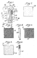
- a wicking structure 20 Adjacent to the anode is provided a wicking structure 20 formed from a 12 mm thick sheet 22 of 85 pore reticulated polyether polyurethane foam that has been felted, or compressed, to one sixth of its original thickness (2 mm). See also FIGs. 3 and 4.
- the felted foam is cut to size, and a thin, expanded metal foil 24 is partially wrapped around the sheet, so as to cover the entire MEA side of the sheet 22 .
- the expanded metal foil we used was Delker 1.5Ni5-050F nickel screen. As shown in FIG. 1, the foil 24 wraps around the top and bottom edges of the foam sheet 22 so that a portion of the foil also contacts the side of the sheet facing away from the MEA 12.
- the foil 24 is crimped in place on the sheet 22.
- the wicking structure 20 will wick and collect water and will collect current. It helps to distribute the liquid fuel and on the anode side of the fuel cell, and helps to hydrate the PEM 14.
- the fuel may be liquid methanol or an aqueous solution of methanol mixed with water, wherein methanol comprises from 3 to 5% of the solution.
- methanol comprises from 3 to 5% of the solution.
- Other liquid fuels providing a source of hydrogen ions may be used, but methanol is preferred.
- Bipolar plate 26 Adjacent to the wicking structure 20 is bipolar plate 26 .
- Bipolar plate 26 is an electrical conductive material and has formed therein channels 28 for directing the flow of liquid fuel to the anode side of the fuel cell. Arrow 29 indicates the direction of the flow of liquid fuel into the channels 28 in bipolar plate 26.
- a second wicking structure 30 Adjacent to the cathode 18 is provided a second wicking structure 30 formed from a 12 mm thick sheet 32 of 85 pore reticulated polyether polyurethane foam that has been felted, or compressed, to one sixth of its original thickness (2 mm). See also FIG. 2.
- the felted foam is perforated with a regularisquare grid pattern of holes with a diameter of 0.5 mm each, leaving a perforation void volume of approximately 18% in the sheet.
- the felted foam is then cut to size and a thin, expanded metal foil 36 (Delker 1.5Ni5-050F nickel screen) is partially wrapped around the sheet, so as to cover the entire MEA side of the sheet 32. As shown in FIG.
- the foil 36 wraps around the top and bottom edges of the foam sheet 32 so that a portion of the foil 36 also contacts the side of the sheet facing away from the MEA 12 .
- the second wicking structure 30 will wick and collect water and will collect current. It helps to remove water from the cathode side of the fuel cell to prevent flooding, and allows air to contact the cathode side to ensure oxygen continues to reach the active sites.
- Bipolar plate 38 Adjacent to the second wicking structure 30 is a bipolar plate 38 .
- Bipolar plate 38 is an electrical conductive material and has formed therein channels 40 for directing the flow of oxidizing gas, such as oxygen or air, to the cathode side of the fuel cell 10 .
- Arrow 42 indicates the flow of gas into one of the channels 40 in the bipolar plate 38 .
- the liquid fuel (methanol) 29 reacts at the surface of the anode to liberate hydrogen ions (H + ) and electrons (e - ).
- the hydrogen ions (H + ) pass through the PEM 14 membrane and combine with oxygen 42 and electrons on the cathode side producing water.
- Electrons (e - ) cannot pass through the membrane and flow from the anode to the cathode through an external circuit 44 containing an electric load 46 that consumes the power generated by the cell.
- the products of the reactions at the anode and cathode are carbon dioxide (CO 2 ) and water (H 2 O), respectively.
- the wicking structure 30 collects the water produced at the cathode 18 and wicks it away from the reactive sites on the cathode.
- the water may then be carried through liquid flow path 48 , which may be piping or tubing to a reservoir or mixing point for mixing with pure liquid fuel to form an aqueous liquid fuel solution. Due to the capillary action of the wicking structure, which holds liquid within voids or pores in that structure, pumping or drawing forces must be applied to draw the water from the second wicking structure 30 into the liquid flow path 48 .
- Pump 49 is one means for drawing water out of the wicking structure 30 for recycling with the liquid fuel supply.
- a particularly preferred pump is a micro-dose dispensing pump or micro-pump, that will pump 0.8 microliters per pulse, such as is available from Pump Works, Inc. Alternative pumping means are readily apparent to those of skill in the art.
- the wicking structures according to the invention have a thickness in the range of 0.1 to 10 mm, preferably from 0.5 to 4.0 mm, and most preferably less than about 2.0 mm.
- the wicking structures are formed from wicking materials of foam, bundled fiber and nonwoven fiber, or combinations of these materials.
- the following materials are particularly preferred: polyurethane foam, felted polyurethane foam, reticulated polyurethane foam, felted reticulated polyurethane foam, melamine foam, cellulose foam, nonwoven felts or bundles of nylon, polypropylene, polyester, cellulose, polyethylene terephthalate, polyethylene, polypropylene and polyacrylonitrile, and mixtures thereof.
- a polyurethane foam is selected for the wicking structure, such foam should have a density in the range of 0.5 to 25 pounds per cubic foot, and pore sizes in the range of 10 to 200 pores per linear inch, preferably a density in the range of 0.5 to 15 pounds per cubic foot and pore sizes in the range of 40 to 200 pores per linear inch, most preferably a density in the range of 0.5 to 10 pounds per cubic foot and pore sizes in the range of 75 to 200 pores per linear inch.
- Felting is carried out under applied heat and pressure to compress a foam structure to an increased firmness and reduced void volume. Once felted, the foam will not rebound to its original thickness, but will remain compressed. Felted foams generally have improved capillarity and water holding than unfelted foams. If a felted polyurethane foam is selected for the wicking structure, such foam should have a density in the range of 2.0 to 45 pounds per cubic foot and a compression ratio in the range of 1.1 to 30, preferably a density in the range of 3 to 15 pounds per cubic foot and compression ratio in the range of 1.1 to 20, most preferably a density in the range of 3 to 15 pounds per cubic foot and compression ratio in the range of 2.0 to 15.
- the conductive layer associated with the sheet of wicking material to form the preferred embodiments of the wicking structure may be a metal screen or an expanded metal foil or metal wool.
- Exemplary metals for this application are gold, platinum, nickel, stainless steel, tungsten, rhodium, cobalt, titanium, silver, copper, chrome, zinc, iconel, and composites or alloys thereof. Metals that will not corrode in moist environments will be suitable for the conductive layer.
- the conductive layer might also be a conductive carbon coating or a paint or coating having conductive particles dispersed therein.
- the metal foil is crimped around the sheet of wicking material.
- the conductive layer may be connected or attached to the surface of the wicking material.
- the wicking material is a foam and the conductive layer is a metal substrate, the conductive layer may be laminated directly to the surface of the foam without adhesives.
- the surface of the foam may be softened by heating and the conductive layer applied to the softened foam surface.
- the conductive layer may be compressed into the foam when the foam is felted.
- the conductive layer is formed with a coating, the coating may be applied to the wicking material by various methods known to those skilled in the art, such as painting, vapor deposition, plasma deposition, arc welding and electroless plating.
- wicking structures are ideal for use in fuel cells to power portable electronic equipment, such as cell phones, which do not remain in a fixed orientation during use.
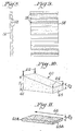
- FIGs. 5 and 6 show an alternative wicking structure 50 for use on the cathode side of the liquid fuel cell.
- the felted foam is perforated with a regular square grid pattern of holes 52 with a diameter of 0.5 mm each, leaving a void volume of approximately 18% in the sheet. While this embodiment lacks a conductive layer or coating, the wicking structure 50 will wick and collect water from the cathode side of the liquid fuel cell and will also permit oxygen source gas to contact the cathode side of the MEA through the perforations 52 to prevent flooding.
- FIG. 7 shows an alternative wicking structure 54 for use on the anode or cathode side of the liquid fuel cell.
- the open structure having voids between the strands of the foam, which permit fluid to flow therein due to the reticulation, will wick and hold water or liquid fluid or a liquid fluid aqueous solution. While this embodiment lacks a conductive layer or coating, the wicking structure 54 will wick and collect water from the cathode side of a liquid fuel cell. If installed on the anode side, this embodiment will distribute and hold liquid fuel, and help to hydrate the PEM.
- FIGs. 8 and 9 show one configuration for a sheet 56 of wicking material formed with channels 58 .
- the channels 58 are shown in a regular, parallel array, but may be provided in alternative configurations as suited to the application.
- the channels provide gaps for increased air flow.
- the wicking material may include a combination (not shown) of channels and holes or perforations to further increase air flow to the electrodes in the fuel cell, particularly the cathode. This wicking material alone may form a wicking structure, or may be combined with a conductive layer (not shown in FIGs. 8 and 9).
- FIGs. 10 and 11 illustrate schematically the method for making a wicking material, such as a foam, with a gradient capillarity.
- a wedge-shaped slab 60 of foam of consistent density and pore size has a thickness T1 at a first end 61 and a second thickness T2 at a second end 65 .
- the slab 60 is subjected to a felting step - high temperature compression for a desired time to compress the slab 60 to a consistent thickness T3, which is less than the thicknesses T1 and T2.
- a greater compressive force, represented by arrows 62 is required to compress the material from T1 to T3 at the first end 61 than is the compressive force, represented by arrows 64 required to compress the material from T2 to T3 at the second end 65.
- the compression ratio of the foam material varies along the length of the felted foam shown in FIG. 11, with the greatest compression at the first end 61 (T1 to T3).
- the capillary pressure is inversely proportional to the effective capillary radius, and the effective capillary radius decreases with increasing firmness or compression.
- Arrow 66 in FIG. 11 represents the direction of capillary flow from the region of lower felt firmness or capillarity to higher felt firmness.
- the wicking material of the wicking structure is felted to a differential degree of compression from one region to another, such that the capillarity of the wicking material varies across its length. In this manner, liquids held within the wicking material may be directed to flow away from one region to another region of the wicking material.
- Such differential degree of felting in a wicking material within a wicking structure adjacent to the cathode will help to draw water away from the cathode side of the fuel cell.
- Such differential degree of felting in a wicking material within a wicking structure adjacent to the anode will help to draw liquid fuel into the fuel cell.
- FIG. 12 schematically shows an embodiment of the liquid fuel cell 100 of the present invention containing a PEM 104 with the recirculation of the product water from the cathode 106 to the anode 102 .
- the cathode has a cathode wicking structure 110 incorporated therein and a layer 108 containing a catalyst.
- the product water at the cathode is wicked by the cathode wicking structure 110, which water is carried away from the cathode wicking structure by water drawing means 114 and placed in water flow path 112 Water in the water flow path 112 is mixed with concentrated liquid fuel in concentrated liquid fuel line 116 to form an aqueous liquid fuel in the liquid fuel flow path 118 which delivers the aqueous liquid fuel to the anode.
- FIG. 13 schematically shows another embodiment of the liquid fuel cell 120 of the present invention containing a PEM 104 with the recirculation of the product water from the cathode 122 to the anode 102 .
- Adjacent to the cathode is a cathode wicking structure 124.
- FIG. 14 schematically shows an embodiment of the liquid fuel cell 132 of the present invention containing a PEM 104 with the recirculation of the product water from the cathode 106 to the anode 126 , wherein the anode has anode wicking structure 128 incorporated therein.
- the cathode has a cathode wicking structure 110 incorporated therein and a layer 108 containing a catalyst.
- the product water at the cathode is wicked by the cathode wicking structure 110, which water is carried away from the cathode wicking structure by water drawing means 114 and placed in water flow path 112.
- Water in the water flow path 112 is mixed with concentrated liquid fuel in concentrated liquid fuel line 116 to form an aqueous liquid fuel in the liquid fuel flow path 118 which delivers the aqueous liquid fuel to an anode wicking structure 128 adjacent to a layer 130 containing a catalyst.
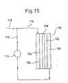
- FIG. 15 schematically shows another embodiment of the liquid fuel cell 134 of the present invention containing a PEM 104 with the recirculation of the product water from the cathode 122 to the anode 136.
- Adjacent to the cathode is a cathode wicking structure 124 and adjacent to the anode is an anode wicking structure 138 .
- FIG. 16 schematically shows an embodiment of the liquid fuel cell 140 of the present invention containing a PEM 104 with the recirculation of the product water from the cathode 122 to the anode 102.
- Adjacent to the cathode is a cathode wicking structure 144 having grooves 142 on the surface facing the cathode.
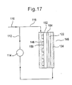
- FIG. 17 schematically shows an embodiment of the liquid fuel cell 14 6 of the present invention with the recirculation of the product water from the cathode 122 to the anode 152 .
- Adjacent to the cathode is a cathode wicking structure 124 .
- Adjacent to the anode is an anode wicking structure 148 having grooves 150 on the surface facing the anode.
- FIG. 18 schematically shows another embodiment of the liquid fuel cell 160 of the present invention with the recirculation of the product water from the cathode 122 to the anode 152 .
- Adjacent to the cathode is a cathode wicking structure 124 .
- Adjacent to the anode is an anode wicking structure 154 having grooves 156 on the surface facing the anode and grooves 158 on the surface facing away from the anode.
- the grooves on the surface of the anode wicking structure facing away from the anode aid in the delivery of the aqueous liquid fuel to the anode.
- the grooves on the surface of the anode wicking structure facing the anode aid in the removal of carbon dioxide from the anode.
- FIG. 19 schematically shows another embodiment of the liquid fuel cell 166 of the present invention with the recirculation of the product water from the cathode 122 to the anode 152 .
- Adjacent to the cathode is a cathode wicking structure 124 .
- Adjacent to the anode is an anode wicking structure 162 having grooves 164 on the surface facing away from the anode. The grooves on the surface of the anode wicking structure facing away from the anode aid in the delivery of the aqueous liquid fuel to the anode.
- FIG. 20 is a schematic diagram showing an embodiment of the liquid fuel cell of the invention having perforation(s) in the wicking structure of at least one of the electrodes.
- the liquid fuel cell contains MEA 180 , comprising anode 174 , PEM 176 , cathode 178 and an anode wicking structure 170 having holes 172 adjacent to the anode.
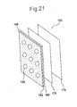
- FIG. 21 is a schematic diagram showing an embodiment of the liquid fuel cell of the invention having perforation(s) in the wicking structure of at least one of the electrodes.
- the liquid fuel cell contains MEA 190 , comprising anode 188 , PEM 176 and cathode 178, wherein the anode comprises a layer 184 having a catalyst and an anode wicking structure 182 having holes 186, with the anode wicking structure incorporated in the anode.
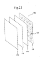
- FIG. 22 is a schematic diagram showing an embodiment of the liquid fuel cell of the invention having perforation(s) in the wicking structure of at least one of the electrodes.
- the liquid fuel cell contains MEA 196 , comprising anode 174 , PEM 176 , cathode 178 and a cathode wicking structure 192 having holes 194 adjacent to the cathode.
- FIG. 23 is a schematic diagram showing an embodiment of the liquid fuel cell of the invention having perforation(s) in the wicking structure of at least one of the electrodes.
- the liquid fuel cell contains MEA 206 , comprising anode 174 , PEM 176 and cathode 204 , wherein the cathode comprises a layer 200 having a catalyst and a cathode wicking structure 198 having holes 202 , with the cathode wicking structure incorporated in the cathode.
- FIG. 24 is a schematic diagram showing an embodiment of the liquid fuel cell of the invention having perforation(s) in the wicking structure of at least one of the electrodes.
- the liquid fuel cell contains MEA 208, comprising anode 174, PEM 176, cathode 178, a cathode wicking structure 192 having holes 194 adjacent to the cathode and an anode wicking structure 170 having holes 172 adjacent to the anode.
- Another aspect of the present invention is directed to liquid fuel cells with the recirculation of the product water from the cathode to the anode, wherein there is no external water added to the liquid fuel cell.
- the water drawn from the cathode wicking structure is substantially the only water supplied to anode in the aqueous liquid fuel.
- the water drawn from the cathode wicking structure and any water present in the concentrated liquid fuel is the only water supplied to anode.
- the liquid fuel can be methanol, ethanol, ethylene glycol, trimethoxymethane, dimethoxymethane, formic acid and hydrazine, with methanol being preferred.
- the concentrated liquid fuel can be pure methanol or an aqueous mixture of methanol having a methanol concentration of at least about 25%, at least about 50%, at least about 65%, about 70% to about 99%, about 80% to about 98%, or about 85% to about 95%.
- the percentage of methanol in the aqueous methanol mixture is expressed in a weight-to-weight basis.
Abstract
Water recovery in direct liquid fuel cells, particularly direct methanol fuel cells, is
accomplished by incorporating a wicking structure composed of a wicking material,
which may be a composite material, adjacent to the cathode. The wicking material has
a free rise wick height of at least one half its longest dimension. The wicking materials
may be selected from foams, matted fibers, bundled fibers, woven fibers and nonwoven
fibers. In one embodiment, holes or perforations are formed through the thickness of
the sheet, and a conductive layer is adjacent to, adhered to or coated on at least one
surface of the wicking material. To recycle water, a second wicking structure of wicking
material is incorporated adjacent to the anode, and a liquid flow path is provided
between the first and second wicking structures. The absorbed water flows through the
liquid flow path, is mixed with fuel and introduced to the second wicking structure
adjacent to the anode.
Description
- This application claims the benefit of U.S. Patent Application No. 09/897,782 filed on June 29, 2001, the disclosure of which is incorporated by reference.
- This invention relates to liquid fuel cells in which the liquid fuel is directly oxidized at the anode. In particular, it relates to wicking structures at or adjacent to the cathode to collect discharged water and wicking structures at or adjacent to the anode to meter or deliver liquid fuel/water mixtures to the anode in direct methanol fuel cells. The invention also relates to a water recovery and recycling system to deliver recovered water to a fuel cell or a micro fuel cell reformer.
- Electrochemical fuel cells convert reactants, namely fuel and oxidants, to generate electric power and reaction products. Electrochemical fuel cells generally employ an electrolyte disposed between two electrodes (an anode and a cathode). An electrocatalyst is needed to induce the desired electrochemical reactions at the electrodes. Solid polymer fuel cells operate in a temperature range of from about 0 □ C to the boiling point of the fuel, i.e., for methanol about 65 □ C, or the boiling point of the fuel mixture, and are particularly preferred for portable applications. Liquid feed solid polymer fuel cells include a membrane electrode assembly ("MEA"), which comprises a solid polymer electrolyte or proton-exchange membrane, sometimes abbreviated "PEM", disposed between two electrode layers. Flow field plates for directing the reactants across one surface of each electrode are generally disposed on each side of the membrane electrode assembly. These plates may also be called the anode backing and cathode backing.
- A broad range of reactants have been contemplated for use in solid polymer fuel cells, and such reactants may be delivered in gaseous or liquid streams. The oxidant stream may be substantially pure oxygen gas, but preferably a dilute oxygen stream such as found in air, is used. The fuel stream may be substantially pure hydrogen gas, or a liquid organic fuel mixture. A fuel cell operating with a liquid fuel stream wherein the fuel is reacted electrochemically at the anode (directly oxidized) is known as a direct liquid feed fuel cell.
- A direct methanol fuel cell ("DMFC") is one type of direct/liquid feed fuel cell in which the fuel (liquid methanol) is directly oxidized at the anode. The following reactions occur:
- Other liquid fuels may be used in direct liquid fuel cells besides methanol -- i.e., other simple alcohols, such as ethanol, or dimethoxymethane, trimethoxymethane and formic acid. Further, the oxidant may be provided in the form of an organic fluid having a high oxygen concentration - i.e., a hydrogen peroxide solution.
- A direct methanol fuel cell may be operated on aqueous methanol vapor, but most commonly a liquid feed of a diluted aqueous methanol fuel solution is used. It is important to maintain separation between the anode and the cathode to prevent fuel from directly contacting the cathode and oxidizing thereon (called "cross-over"). Crossover results in a short circuit in the cell since the electrons resulting from the oxidation reaction do not follow the current path between the electrodes. To reduce the potential for cross-over of methanol fuel from the anode to the cathode side through the MEA, very dilute solutions of methanol (for example, about 5% methanol in water) are typically used as the fuel streams in liquid feed DMFCs.
- The polymer electrolyte membrane (PEM) is a solid, organic polymer, usually polyperfluorosulfonic acid that comprises the inner core of the membrane electrode assembly (MEA). Commercially available polyperfluorosulfonic acids for use as PEMs are sold by E.I. DuPont de Nemours & Company under the trademark NAFION®. The PEM must be hydrated to function properly as a proton (hydrogen ion) exchange membrane and as an electrolyte.
- Substantial amounts of water are liberated at the cathode and must be removed so as to prevent flooding the cathode and halting the reaction. In prior art fuel cells, if the air flow past the cathode is too slow, the air cannot carry all of the water present at the cathode out of the fuel cell. With water flooding the cathode, not enough oxygen is able to penetrate past the water to reach the cathode catalyst sites to maintain the reaction.
- Prior art fuel cells incorporated porous carbon paper or cloth as backing layers adjacent the PEM of the MEA. The porous carbon materials not only helped to diffuse reactant gases to the electrode catalyst sites, but also assisted in water management. Porous carbon was selected because carbon conducts the electrons exiting the anode and entering the cathode. However, porous carbon has not been found to be an effective material for wicking excess water away from the cathode. Nor has porous carbon been found effective to meter fluid to the anode. And porous carbon paper is expensive. Consequently, the fuel cell industry continues to seek backing layers that will improve liquid recovery and removal, and maintain effective gas diffusion, without adversely impacting fuel cell performance or adding significant expense.
- It would also be advantageous to recycle the water liberated at the cathode for use as the diluent in the liquid fuel delivery system. Such recycled water could be mixed with concentrated methanol before introducing the liquid fuel to the fuel cell. Substantial space and weight savings would result if fuel cartridges contained predominantly methanol, and that methanol could then be diluted to an aqueous solution of from about 3 to 5% methanol concentration using recycled water emitted by the fuel cell reaction. The fuel cartridge carried with the fuel cell containing predominantly methanol could be smaller and lighter weight. A material that can wick the excess water away from the cathode must also be able to release the collected water for recycling into the liquid fuel. Prior art carbon paper backing layers do not meet these competing criteria.
- While the prior art has identified recycling the liberated water to mix with pure methanol before introducing the liquid fuel into the direct methanol liquid fuel cell as one goal for improving fuel cell performance, there is no disclosure of an effective means of recovering and recycling such water independent of fuel cell orientation. The problem is particularly acute for fuel cells intended to be used in portable applications, such as in consumer electronics and cell phones, where the fuel cell orientation with respect to gravitational forces will vary.
- According to a first embodiment of the invention, a wicking structure is installed substantially adjacent to a cathode or an anode of a liquid fuel cell. The wicking structure comprises a wicking material into which a liquid wicks and from which said liquid subsequently may be metered or discharged. The wicking structure thus not only wicks and retains liquids, but permits liquids to be controllably metered out or delivered from such structure. The wicking material used to make the wicking structure can also be electrically conductive so that the wicking structure can conduct electricity.
- The wicking structure has a geometry having a longest dimension. For a cylindrical shaped wicking structure, the longest dimension may be either its height or its diameter, depending upon the relative dimensions of the cylinder. For a rectangular box-shaped wicking structure, the longest dimension may be either its height or its length or its thickness, depending upon the relative dimensions of the box. For other shapes, such as a square box-shaped reservoir, the longest dimension may be the same in multiple directions. The free rise wick height (a measure of capillarity) of the wicking structure preferably is greater than at least one half of the longest dimension. Most preferably, the free rise wick height is greater than the longest dimension.
- The wicking structure may be made from foams, matted fibers, bundled fibers, woven fibers or nonwoven fibers. The wicking structure for the anode can in general be a porous member made of one or more polymers resistant to the liquid fuel. Preferably, the wicking structure is constructed from a wicking material selected from polyurethane foam (preferably, a felted polyurethane foam, reticulated polyurethane foam or felted reticulated polyurethane foam), melamine foam, cellulose foam, nonwoven felts or bundles of polyamide such as nylon, polypropylene, polyester such as polyethylene terephthalate, cellulose, polyethylene, polypropylene and polyacrylonitrile, and mixtures thereof. Alternatively, the wicking structure is preferably constructed with a wicking material selected from polyurethane foams (preferably, a felted polyurethane foam, reticulated polyurethane foam or felted reticulated polyurethane foam), melamine foams, cellulose foams, nonwoven felts of a polyamide such as nylon, polyethylene, polypropylene, polyester such as polyethylene terephthalate, polyacrylonitrile, or mixtures thereof, bundled, matted or woven fibers of cellulose, polyethylene, polypropylene, polyester such as polyethylene terephthalate, polyacrylonitrile, and mixtures thereof. Certain inorganic porous materials, such as sintered inorganic powders of silica or alumina, can also be used as the wicking material for the wicking structure.
- A felted foam is produced by applying heat and pressure sufficient to compress the foam to a fraction of its original thickness. For a compression ratio of 30, the foam is compressed to 1/30 of its original thickness. For a compression ratio of 2, the foam is compressed to 1/2 of its original thickness.
- A reticulated foam is produced by removing the cell windows from the cellular polymer structure, leaving a network of strands and thereby increasing the fluid permeability of the resulting reticulated foam. Foams may be reticulated by in situ, chemical or thermal methods, all as known to those of skill in foam production.
- In a particularly preferred embodiment, the wicking structure is made with a wicking material with a gradient capillarity, such that the flow of the liquid is directed from one region of the structure to another region of the structure as a result of the differential in capillarity between the two regions. One method of producing a foam with a gradient capillarity is to felt the foam to varying degrees of compression along its length. The direction of capillarity flow of liquid is from a lesser compressed region to a greater compressed region. Alternatively, the wicking structure may be made of a composite of individual components of foams or other materials with distinctly different capillarities.
- Because it is important to have gases (air or oxygen) reach the active sites at the cathode, the wicking structure may be formed so as to increase air permeability. Hence, if the wicking structure is a sheet of wicking material, the sheet may define one or more holes through its thickness. Such holes may be formed by perforating or punching the sheet. The holes may be formed in a regular grid pattern or in an irregular pattern. Alternatively, the sheet may define a one or more channels formed in a facing surface. The channels may be formed by cutting, such as by surface modification or convolute cutting as known in the foam fabrication industry. The channels or holes may also be formed using thermo-forming techniques in which the surface of the sheet is contoured under applied heat and pressure.
- Because it is important to have a conductive path for electrons to reach the active sites at the cathode, the wicking structure preferably further comprises a conductive layer either adjacent to or connected to or coated on the wicking material forming the wicking structure. The conductive layer may be a metal screen, a metal wool, or an expanded metal foil. In a preferred embodiment, the conductive layer is attached to a surface of the sheet of wicking material forming the wicking structure, such as by crimping the conductive layer around the sheet. Alternatively, the conductive layer may be a coating coated onto a surface of the sheet or penetrating through the entire thickness of the sheet. Such coatings include metals, carbons and carbon-containing materials, conductive polymers and suspensions or mixtures thereof. Metals may be coated using vapor deposition, plasma, arc and electroless plating techniques, or any other suitable coating technique. In another preferred embodiment, the front and at least a portion of the back surface of a sheet of wicking material is covered with the conductive layer. When the conductive layer is crimped around the sheet, the conductive layer covers also the top and bottom edges of the sheet. The conductive layer is in communication with a current circuit.
- The invention also includes a water recovery system for a direct methanol fuel cell having (a) a wicking structure into which water wicks and from which said water may be metered installed as a backing layer for a cathode in the fuel cell, said wicking structure having a longest dimension and a free rise wick height greater than at least one half of the longest dimension; (b) a liquid flow path in communication with the wicking structure through which absorbed water from the wicking structure flows away from the wicking structure; and (c) a water drawing means, such as a pump or wick, to draw absorbed water from the wicking structure and into the liquid flow path. Water absorbed by the wicking structure is drawn away from the cathode and pumped or directed to a reservoir or channel to be mixed with liquid fuel prior to its introduction to the anode side of the fuel cell.
- The wicking structure in the water recovery system is made from a wicking material selected from the group consisting of foam, matted, bundled or woven fibers and nonwoven fibers. Preferably, the wicking structure has a conductive layer associated therewith, which may be a separate layer adjacent to the wicking material or may be attached or coated thereon. The conductive layer is in communication with a current circuit.
- In one of the embodiments, a second wicking structure is installed as the backing layer for an anode in the fuel cell. The second wicking structure may have the same or different construction from the first wicking structure. The second wicking structure has a longest dimension and a free rise wick height greater than at least one half of its longest dimension, preferably greater than its longest dimension. The recovered and recycled water mixed with the liquid fuel is directed to the second wicking structure to re-fuel the liquid fuel cell reaction at the anode.
- In another embodiment of the invention, liquid fuel cell performance is improved by incorporating as a backing layer for the cathode, and optionally as a backing layer for the anode, the wicking structure of the first embodiment of the invention. Because the wicking structure efficiently and effectively wicks water away from the cathode, the reaction continues without flooding caused by the water emitted by the fuel cell. The absorbed collected water may be recycled and mixed with a source of liquid fuel before re-introducing it to the anode side of the fuel cell. Preferably the recycled water mixed with fuel is introduced to a wicking structure forming a backing layer for the anode. This second wicking structure when so wetted with the recycled water and fuel helps both to distribute the fuel and to keep the PEM hydrated.
- Within the scope of the invention is a liquid fuel cell, comprising
an anode supplied with an aqueous liquid fuel which is oxidized at said anode;
a cathode supplied with a gaseous oxidant;
a solid polymer electrolyte membrane disposed between said anode and cathode;
a liquid fuel flow path which delivers the liquid fuel to the anode;
a water flow path which delivers water to the liquid fuel flow path;
a concentrated liquid fuel line which delivers concentrated liquid fuel to the liquid fuel flow path to mix with water therein to form the aqueous liquid fuel;
a cathode wicking structure incorporated in the cathode or in fluid communication therewith, wherein the cathode wicking structure comprises a cathode wicking material into which water can wick and from which the water can be released, said cathode wicking material having a cathode wicking material longest dimension and a free rise wick height greater than one half of the cathode wicking material longest dimension (preferably, the free rise wick height is greater than the cathode wicking material longest dimension); and
a water drawing means for drawing water from the cathode wicking structure to the water flow path. In some of the embodiments, the cathode wicking structure has a thickness and defines at least one hole through the thickness having a size such as to deliver an effective amount of the gaseous oxidant to the cathode to conduct an oxidizing reaction at the cathode. Preferably, the cathode wicking structure has a plurality of holes through said thickness, and wherein the number and size of the holes deliver therethrough an effective amount of the gaseous oxidant to the cathode to conduct the oxidizing reaction at the cathode. - Another aspect of the present invention is a method for liquid management in a liquid fuel cell having an anode and a cathode, said method comprising the steps of:
- (a) wicking water from the cathode into a cathode wicking structure in fluid communication with the cathode, wherein the cathode wicking structure comprises a cathode wicking material into which water can wick and from which water can be released, said cathode wicking material having a cathode wicking material longest dimension and a first free rise wick height greater than one half of the cathode wicking material longest dimension;
- (b) releasing water from the cathode wicking structure;
- (c) providing a source of a concentrated liquid fuel;
- (d) mixing water released from the cathode wicking structure in step (b) with the concentrated liquid fuel from the source to form an aqueous liquid fuel; and thereafter
- (e) supplying the aqueous liquid fuel to the anode by delivering the aqueous liquid fuel mixture to the anode.
-
- In an embodiment of the method for liquid management of the invention, step (b) is conducted by drawing water from the cathode wicking structure using a water drawing means to deliver water into a water flow path. The water drawing means can be a pump or a wick having more capillarity than the cathode wicking structure to deliver water into a water flow path.
- In another embodiment of the method for liquid management of the invention, step (e) is conducted by delivering the aqueous liquid fuel to an anode wicking structure incorporated in the anode or in fluid communication with the anode, wherein the anode wicking structure comprises an anode wicking material into which the aqueous liquid fuel can wick and from which the aqueous liquid fuel can be released, said anode wicking material having an anode wicking material longest dimension and a free rise wick height greater than one half of the anode wicking material longest dimension. In step (e), the aqueous liquid fuel can be delivered to the anode wicking structure incorporated in the anode or in fluid communication with the anode by an aqueous liquid fuel delivery means. The aqueous liquid fuel delivery means can be a pump or a wick having less capillarity than the anode wicking structure.
-
- FIG. 1 is schematic view in side elevation of a direct methanol fuel cell incorporating the wicking structures according to the invention;
- FIG. 2 is a top plan view of a first embodiment of a wicking structure according to the invention that includes a perforated sheet covered with a metal screen;
- FIG. 3 is a top plan view of a second embodiment of a wicking structure according to the invention that includes a sheet without perforations covered with a metal screen;
- FIG. 4 is a left side elevational view of the wicking structure of FIG. 3;
- FIG. 5 is a top plan view of a third embodiment of a wicking structure according to the invention that includes a perforated sheet without a metal screen covering;
- FIG. 6 is a right side elevational view of the wicking structure of FIG. 5, wherein the view is partially broken away to show the perforations extending through the sheet;
- FIG. 7 is a top plan view of a fourth embodiment of a wicking structure according to the invention that lacks perforations and lacks a metal screen covering;
- FIG. 8 is a top plan view of a fifth embodiment of a wicking structure according to the invention having channels;
- FIG. 9 is a left side elevational view of the wicking structure of FIG. 8;
- FIG. 10 is a schematic diagram of a wedge of wicking material prior to felting; and
- FIG. 11 is a schematic diagram of the wicking material of FIG. 10 after felting.
- FIG. 12 is schematic diagram of an embodiment of the liquid fuel cell according to the invention, with recirculation of the product water from the cathode to be mixed with a concentrated liquid fuel in order to supply the anode with an aqueous liquid fuel.
- FIG. 13 is schematic diagram of another embodiment of the liquid fuel cell according to the invention, with recirculation of the product water from the cathode.
- FIG. 14 is schematic diagram of another embodiment of the liquid fuel cell according to the invention, with recirculation of the product water from the cathode.
- FIG. 15 is schematic diagram of another embodiment of the liquid fuel cell according to the invention, with recirculation of the product water from the cathode.
- FIG. 16 is schematic diagram of another embodiment of the liquid fuel cell according to the invention, with recirculation of the product water from the cathode.
- FIG. 17 is schematic diagram of another embodiment of the liquid fuel cell according to the invention, with recirculation of the product water from the cathode.
- FIG. 18 is schematic diagram of another embodiment of the liquid fuel cell according to the invention, with recirculation of the product water from the cathode.
- FIG. 19 is schematic diagram of another embodiment of the liquid fuel cell according to the invention, with recirculation of the product water from the cathode.
- FIG. 20 is a schematic diagram of an embodiment of a membrane electrode assembly in a liquid fuel cell according to the invention, with perforation of the anode wicking structure.
- FIG. 21 is a schematic diagram of another embodiment of a membrane electrode assembly in a liquid fuel cell according to the invention, with perforation of the anode wicking structure.
- FIG. 22 is a schematic diagram of an embodiment of a membrane electrode assembly in a liquid fuel cell according to the invention, with perforation of the cathode wicking structure.
- FIG. 23 is a schematic diagram of another embodiment of a membrane electrode assembly in a liquid fuel cell according to the invention, with perforation of the cathode wicking structure.
- FIG. 24 is a schematic diagram of another embodiment of a membrane electrode assembly in a liquid fuel cell according to the invention, with perforation of the anode and cathode wicking structures.
-
- The present invention is also directed to the liquid fuel cell described above, wherein
the cathode wicking structure is incorporated in the cathode;
the cathode further comprises a first cathode surface, second cathode surface and catalyst on the second cathode surface, said second cathode surface being adjacent to the solid polymer electrolyte membrane and said first cathode surface facing away from the solid polymer electrolyte membrane; and
the cathode wicking structure is planar and has first and second cathode wicking structure surfaces, said second cathode wicking structure surface being adjacent to the catalyst, the first cathode wicking structure surface forming the first cathode surface. Optionally, said first cathode wicking structure surface has at least one groove thereon with a size such as to deliver an amount of the gaseous oxidant to the cathode to conduct an oxidizing reaction thereon. Preferably, said first cathode wicking structure surface has a plurality of grooves thereon, wherein the number and size of the grooves are such as to deliver an effective amount of the gaseous oxidant to the cathode to conduct the oxidizing reaction at the cathode. - The present invention is also directed to the liquid fuel cell described above, wherein
the cathode wicking structure is external to but in fluid communication with the cathode;
the cathode further comprises a first cathode surface and second cathode surface, said second cathode surface being adjacent to the solid polymer electrolyte membrane and said first cathode surface facing away from the solid polymer electrolyte membrane; and
the cathode wicking structure is planar and has a first and second cathode wicking structure surfaces, said second cathode wicking structure surface being adjacent to the first cathode surface and said first cathode wicking structure surface facing away from the cathode. Optionally, said second cathode wicking structure surface has at least one groove thereon with a size such as to deliver an amount of the gaseous oxidant to the cathode to conduct an oxidizing reaction thereon. Preferably, said second cathode wicking structure has a plurality of grooves thereon, wherein the number and size of the grooves are such as to deliver an effective amount of the gaseous oxidant to the cathode to conduct the oxidizing reaction at the cathode. - Within the scope of the present invention is any of the liquid fuel cells described above further comprising a wicking structure at the anode. The anode wicking structure can be incorporated in the anode or in fluid communication therewith, wherein the anode wicking structure comprises an anode wicking material into which the liquid fuel can wick and from which the liquid fuel can be released, said anode wicking material having an anode wicking material longest dimension and a free rise wick height greater than one half of the anode wicking material longest dimension, and said anode wicking structure being in fluid communication with the liquid fuel flow path. The free rise wick height of the anode wicking material is preferably greater than the anode wicking material longest dimension. Optionally, the anode wicking structure has a thickness and defines at least one hole through said thickness having an opening area sized to permit the removal of carbon dioxide from the anode. Preferably, the anode wicking structure has a plurality of holes through said thickness having a total opening area sized to permit the removal of carbon dioxide from the anode.
- In the liquid fuel cell of the invention having the anode wicking structure, the anode wicking structure can be incorporated in the anode, wherein
the anode further comprises a first anode surface, a second anode surface and catalyst on the second anode surface, said second anode surface being adjacent to the solid polymer electrolyte membrane and said first anode surface facing away from the solid polymer electrolyte membrane; and
the anode wicking structure is planar and has a first and second anode wicking structure surfaces, said second anode wicking structure surface being adjacent to the catalyst, said first anode wicking structure surface forming the first anode surface. Optionally, said first anode wicking structure surface has at least one groove thereon with a size such as to allow carbon dioxide to escape from the anode. Preferably, said first anode wicking structure surface has a plurality of grooves thereon, wherein the number and size of the grooves are such as to allow carbon dioxide to escape from the anode. - In another embodiment of the liquid fuel cell having an anode wicking structure, the anode wicking structure is external to but in fluid communication with the anode, wherein
the anode further comprises a first anode surface and a second anode surface, said second anode surface being adjacent to the solid polymer electrolyte membrane and said first anode surface facing away from the solid polymer electrolyte membrane; and
the anode wicking structure is planar and has a first and second anode wicking structure surfaces, said second anode wicking structure surface being adjacent to the first anode surface and said first anode wicking structure surface facing away from the anode. Optionally, said first anode wicking structure surface has at least one groove thereon with a size such as to allow carbon dioxide to escape from the anode.
Preferably, said first anode wicking structure surface has a plurality of grooves thereon, wherein the number and size of the grooves are such as to allow carbon dioxide to escape from the anode. - The present invention is also directed to any liquid fuel cells comprising an anode, polymer electrolyte membrane and cathode, wherein either or both electrodes have wicking structures, wherein the wicking structure of at least one of the electrodes has at least one hole through its thickness. The hole(s) at the cathode wicking structure aids in the delivery of the gaseous oxidant to the cathode for the oxidizing reaction at the cathode. The hole(s) at the anode wicking structure aids in the removal of carbon dioxide from the anode. In some of the embodiments of the liquid fuel cells, the cathode wicking structure has at least one hole, the anode wicking structure has at least one hole, or both the cathode and anode wicking structures have at least one hole.
- In the liquid fuel cell of the present invention with recirculation of the product water from the cathode to the anode, the liquid fuel cell can have at least one hole through the wicking structure of one or both electrodes, at least one groove on the surface of the wicking structure of one or both electrodes, a combination of at least one hole and at least one groove at one or both electrodes, at least one hole at the cathode combined with at least one groove at the anode or vice versa, and at least one groove at the cathode combined with at least one hole at the anode or vice versa. The hole(s) or groove(s) at the cathode wicking structure aids in the delivery of the gaseous oxidant to the cathode for the oxidizing reaction at the cathode. The hole(s) or groove(s) at the anode wicking structure aids in the removal of carbon dioxide from the anode.
- In the present invention, the water drawing means can be a pump or a wick having higher capillarity than the cathode wicking structure. Preferably, the water drawing means is a pump, such as a micropump. The aqueous liquid fuel delivery means can be a pump or a wick having less capillarity than the anode wicking structure, with the pump preferred.
- The cathode wicking material or anode wicking material can be foams, bundled fibers, matted fibers, woven fibers, nonwoven fibers or inorganic porous materials. Preferably, the cathode wicking material or anode wicking material is selected from foams, bundled fibers, matted fibers, woven fibers or nonwoven fibers. The cathode wicking material or anode wicking material, more preferably, is selected from polyurethane foam, melamine foam, cellulose foam, nonwoven felts of polyamide such as nylon, polyethylene, polypropylene, polyester such as polyethylene terephthalate, polyacrylonitrile, or mixtures thereof, bundled, matted or woven fibers of cellulose, polyester, polyethylene, polypropylene and polyacrylonitrile, or mixtures thereof. In this application, the term "nylon" refers to any members of the nylon family. The cathode wicking material or anode wicking material, most preferably, is a polyurethane foam such as a felted polyurethane foam, reticulated polyurethane foam or felted reticulated polyurethane foam.
- Referring first to FIG. 1, a direct
methanol fuel cell 10 includes a membrane electrode assembly ("MEA") 12 comprising a polymer electrolyte membrane ("PEM") 14 sandwiched between an anode 16 and a cathode 18. The PEM 14 is a solid, organic polymer, usually polyperfluorosulfonic acid that comprises the inner core of the membrane electrode assembly (MEA). Commercially available polyperfluorosulfonic acids for use as a PEM are sold by E.I. DuPont de Nemours & Company under the trademark NAFION®. Catalyst layers (not shown) are present on each side of the PEM. The PEM must be hydrated to function properly as a proton (hydrogen ion) exchanger and as an electrolyte. - The anode 16 and cathode 18 are electrodes separated from one another by the PEM. The anode carries a negative charge, and the cathode carries a positive charge.
- Adjacent to the anode is provided a
wicking structure 20 formed from a 12 mmthick sheet 22 of 85 pore reticulated polyether polyurethane foam that has been felted, or compressed, to one sixth of its original thickness (2 mm). See also FIGs. 3 and 4. The felted foam is cut to size, and a thin, expandedmetal foil 24 is partially wrapped around the sheet, so as to cover the entire MEA side of thesheet 22. The expanded metal foil we used was Delker 1.5Ni5-050F nickel screen. As shown in FIG. 1, thefoil 24 wraps around the top and bottom edges of thefoam sheet 22 so that a portion of the foil also contacts the side of the sheet facing away from the MEA 12. Thefoil 24 is crimped in place on thesheet 22. Thewicking structure 20 will wick and collect water and will collect current. It helps to distribute the liquid fuel and on the anode side of the fuel cell, and helps to hydrate the PEM 14. - In the direct methanol fuel cell of FIG. 1, the fuel may be liquid methanol or an aqueous solution of methanol mixed with water, wherein methanol comprises from 3 to 5% of the solution. Other liquid fuels providing a source of hydrogen ions may be used, but methanol is preferred.
- Adjacent to the
wicking structure 20 isbipolar plate 26.Bipolar plate 26 is an electrical conductive material and has formed therein channels 28 for directing the flow of liquid fuel to the anode side of the fuel cell.Arrow 29 indicates the direction of the flow of liquid fuel into the channels 28 inbipolar plate 26. - Adjacent to the cathode 18 is provided a
second wicking structure 30 formed from a 12 mmthick sheet 32 of 85 pore reticulated polyether polyurethane foam that has been felted, or compressed, to one sixth of its original thickness (2 mm). See also FIG. 2. The felted foam is perforated with a regularisquare grid pattern of holes with a diameter of 0.5 mm each, leaving a perforation void volume of approximately 18% in the sheet. The felted foam is then cut to size and a thin, expanded metal foil 36 (Delker 1.5Ni5-050F nickel screen) is partially wrapped around the sheet, so as to cover the entire MEA side of thesheet 32. As shown in FIG. 1, thefoil 36 wraps around the top and bottom edges of thefoam sheet 32 so that a portion of thefoil 36 also contacts the side of the sheet facing away from the MEA 12. Thesecond wicking structure 30 will wick and collect water and will collect current. It helps to remove water from the cathode side of the fuel cell to prevent flooding, and allows air to contact the cathode side to ensure oxygen continues to reach the active sites. - Adjacent to the
second wicking structure 30 is abipolar plate 38.Bipolar plate 38 is an electrical conductive material and has formed thereinchannels 40 for directing the flow of oxidizing gas, such as oxygen or air, to the cathode side of thefuel cell 10.Arrow 42 indicates the flow of gas into one of thechannels 40 in thebipolar plate 38. - In operation, the liquid fuel (methanol) 29 reacts at the surface of the anode to liberate hydrogen ions (H+) and electrons (e-). The hydrogen ions (H+) pass through the PEM 14 membrane and combine with
oxygen 42 and electrons on the cathode side producing water. Electrons (e-) cannot pass through the membrane and flow from the anode to the cathode through anexternal circuit 44 containing anelectric load 46 that consumes the power generated by the cell. The products of the reactions at the anode and cathode are carbon dioxide (CO2) and water (H2O), respectively. - The
wicking structure 30 collects the water produced at the cathode 18 and wicks it away from the reactive sites on the cathode. The water may then be carried throughliquid flow path 48, which may be piping or tubing to a reservoir or mixing point for mixing with pure liquid fuel to form an aqueous liquid fuel solution. Due to the capillary action of the wicking structure, which holds liquid within voids or pores in that structure, pumping or drawing forces must be applied to draw the water from thesecond wicking structure 30 into theliquid flow path 48.Pump 49 is one means for drawing water out of thewicking structure 30 for recycling with the liquid fuel supply. A particularly preferred pump is a micro-dose dispensing pump or micro-pump, that will pump 0.8 microliters per pulse, such as is available from Pump Works, Inc. Alternative pumping means are readily apparent to those of skill in the art. - The wicking structures according to the invention have a thickness in the range of 0.1 to 10 mm, preferably from 0.5 to 4.0 mm, and most preferably less than about 2.0 mm.
- The wicking structures are formed from wicking materials of foam, bundled fiber and nonwoven fiber, or combinations of these materials. The following materials are particularly preferred: polyurethane foam, felted polyurethane foam, reticulated polyurethane foam, felted reticulated polyurethane foam, melamine foam, cellulose foam, nonwoven felts or bundles of nylon, polypropylene, polyester, cellulose, polyethylene terephthalate, polyethylene, polypropylene and polyacrylonitrile, and mixtures thereof.
- If a polyurethane foam is selected for the wicking structure, such foam should have a density in the range of 0.5 to 25 pounds per cubic foot, and pore sizes in the range of 10 to 200 pores per linear inch, preferably a density in the range of 0.5 to 15 pounds per cubic foot and pore sizes in the range of 40 to 200 pores per linear inch, most preferably a density in the range of 0.5 to 10 pounds per cubic foot and pore sizes in the range of 75 to 200 pores per linear inch.
- Felting is carried out under applied heat and pressure to compress a foam structure to an increased firmness and reduced void volume. Once felted, the foam will not rebound to its original thickness, but will remain compressed. Felted foams generally have improved capillarity and water holding than unfelted foams. If a felted polyurethane foam is selected for the wicking structure, such foam should have a density in the range of 2.0 to 45 pounds per cubic foot and a compression ratio in the range of 1.1 to 30, preferably a density in the range of 3 to 15 pounds per cubic foot and compression ratio in the range of 1.1 to 20, most preferably a density in the range of 3 to 15 pounds per cubic foot and compression ratio in the range of 2.0 to 15.
- The conductive layer associated with the sheet of wicking material to form the preferred embodiments of the wicking structure may be a metal screen or an expanded metal foil or metal wool. Exemplary metals for this application are gold, platinum, nickel, stainless steel, tungsten, rhodium, cobalt, titanium, silver, copper, chrome, zinc, iconel, and composites or alloys thereof. Metals that will not corrode in moist environments will be suitable for the conductive layer. The conductive layer might also be a conductive carbon coating or a paint or coating having conductive particles dispersed therein.
- As shown in FIGs. 1-4, the metal foil is crimped around the sheet of wicking material. Alternatively, the conductive layer may be connected or attached to the surface of the wicking material. If the wicking material is a foam and the conductive layer is a metal substrate, the conductive layer may be laminated directly to the surface of the foam without adhesives. For example, the surface of the foam may be softened by heating and the conductive layer applied to the softened foam surface. Alternatively, the conductive layer may be compressed into the foam when the foam is felted. If the conductive layer is formed with a coating, the coating may be applied to the wicking material by various methods known to those skilled in the art, such as painting, vapor deposition, plasma deposition, arc welding and electroless plating.
- One advantage of the wicking structures according to the invention is that they not only will wick and hold liquids, but also will release and permit liquids to be metered therefrom in a predictable manner without reliance on or interference from gravitational forces. The capillary action of the wicking material can be controlled, such that the wicking structure will perform regardless of orientation with respect to gravity. Such wicking structures are ideal for use in fuel cells to power portable electronic equipment, such as cell phones, which do not remain in a fixed orientation during use.
- FIGs. 5 and 6 show an
alternative wicking structure 50 for use on the cathode side of the liquid fuel cell. A 12 mm thick 85 pore reticulated polyether polyurethane foam is permanently compressed to one-sixth of its original thickness (2 mm) (compression ratio = 6). The felted foam is perforated with a regular square grid pattern ofholes 52 with a diameter of 0.5 mm each, leaving a void volume of approximately 18% in the sheet. While this embodiment lacks a conductive layer or coating, thewicking structure 50 will wick and collect water from the cathode side of the liquid fuel cell and will also permit oxygen source gas to contact the cathode side of the MEA through theperforations 52 to prevent flooding. - FIG. 7 shows an
alternative wicking structure 54 for use on the anode or cathode side of the liquid fuel cell. A 12 mm thick 85 pore reticulated polyether polyurethane foam is felted (permanently compressed) to one-sixth of its original thickness (2 mm) (compression ratio = 6). The open structure having voids between the strands of the foam, which permit fluid to flow therein due to the reticulation, will wick and hold water or liquid fluid or a liquid fluid aqueous solution. While this embodiment lacks a conductive layer or coating, thewicking structure 54 will wick and collect water from the cathode side of a liquid fuel cell. If installed on the anode side, this embodiment will distribute and hold liquid fuel, and help to hydrate the PEM. - FIGs. 8 and 9 show one configuration for a
sheet 56 of wicking material formed withchannels 58. Thechannels 58 are shown in a regular, parallel array, but may be provided in alternative configurations as suited to the application. The channels provide gaps for increased air flow. The wicking material may include a combination (not shown) of channels and holes or perforations to further increase air flow to the electrodes in the fuel cell, particularly the cathode. This wicking material alone may form a wicking structure, or may be combined with a conductive layer (not shown in FIGs. 8 and 9). - FIGs. 10 and 11 illustrate schematically the method for making a wicking material, such as a foam, with a gradient capillarity. As shown in FIG. 10, a wedge-shaped
slab 60 of foam of consistent density and pore size has a thickness T1 at afirst end 61 and a second thickness T2 at asecond end 65. Theslab 60 is subjected to a felting step - high temperature compression for a desired time to compress theslab 60 to a consistent thickness T3, which is less than the thicknesses T1 and T2. A greater compressive force, represented byarrows 62, is required to compress the material from T1 to T3 at thefirst end 61 than is the compressive force, represented byarrows 64 required to compress the material from T2 to T3 at thesecond end 65. - The compression ratio of the foam material varies along the length of the felted foam shown in FIG. 11, with the greatest compression at the first end 61 (T1 to T3). The capillary pressure is inversely proportional to the effective capillary radius, and the effective capillary radius decreases with increasing firmness or compression.
Arrow 66 in FIG. 11 represents the direction of capillary flow from the region of lower felt firmness or capillarity to higher felt firmness. Thus, if a wicking material or wicking structure is formed with a foam having a gradient capillarity, the liquid fuel wicked into the material may be directed to flow from one region of the material with lower compression ratio to another region with higher compression ratio. - In one preferred embodiment, the wicking material of the wicking structure is felted to a differential degree of compression from one region to another, such that the capillarity of the wicking material varies across its length. In this manner, liquids held within the wicking material may be directed to flow away from one region to another region of the wicking material. Such differential degree of felting in a wicking material within a wicking structure adjacent to the cathode will help to draw water away from the cathode side of the fuel cell. Such differential degree of felting in a wicking material within a wicking structure adjacent to the anode will help to draw liquid fuel into the fuel cell.
- FIG. 12 schematically shows an embodiment of the
liquid fuel cell 100 of the present invention containing aPEM 104 with the recirculation of the product water from thecathode 106 to theanode 102. The cathode has acathode wicking structure 110 incorporated therein and alayer 108 containing a catalyst. The product water at the cathode is wicked by thecathode wicking structure 110, which water is carried away from the cathode wicking structure by water drawing means 114 and placed inwater flow path 112 Water in thewater flow path 112 is mixed with concentrated liquid fuel in concentratedliquid fuel line 116 to form an aqueous liquid fuel in the liquidfuel flow path 118 which delivers the aqueous liquid fuel to the anode. - In FIG. 12 described above, as well as FIGs. 13-24, the electrical connection between the anode and cathode is not shown for the sake of brevity.
- FIG. 13 schematically shows another embodiment of the
liquid fuel cell 120 of the present invention containing aPEM 104 with the recirculation of the product water from thecathode 122 to theanode 102. Adjacent to the cathode is acathode wicking structure 124. - FIG. 14 schematically shows an embodiment of the
liquid fuel cell 132 of the present invention containing aPEM 104 with the recirculation of the product water from thecathode 106 to theanode 126, wherein the anode hasanode wicking structure 128 incorporated therein. The cathode has acathode wicking structure 110 incorporated therein and alayer 108 containing a catalyst. The product water at the cathode is wicked by thecathode wicking structure 110, which water is carried away from the cathode wicking structure by water drawing means 114 and placed inwater flow path 112. Water in thewater flow path 112 is mixed with concentrated liquid fuel in concentratedliquid fuel line 116 to form an aqueous liquid fuel in the liquidfuel flow path 118 which delivers the aqueous liquid fuel to ananode wicking structure 128 adjacent to alayer 130 containing a catalyst. - FIG. 15 schematically shows another embodiment of the
liquid fuel cell 134 of the present invention containing aPEM 104 with the recirculation of the product water from thecathode 122 to theanode 136. Adjacent to the cathode is acathode wicking structure 124 and adjacent to the anode is ananode wicking structure 138. - FIG. 16 schematically shows an embodiment of the
liquid fuel cell 140 of the present invention containing aPEM 104 with the recirculation of the product water from thecathode 122 to theanode 102. Adjacent to the cathode is acathode wicking structure 144 havinggrooves 142 on the surface facing the cathode. - FIG. 17 schematically shows an embodiment of the
liquid fuel cell 146 of the present invention with the recirculation of the product water from thecathode 122 to theanode 152. Adjacent to the cathode is acathode wicking structure 124. Adjacent to the anode is ananode wicking structure 148 havinggrooves 150 on the surface facing the anode. - FIG. 18 schematically shows another embodiment of the
liquid fuel cell 160 of the present invention with the recirculation of the product water from thecathode 122 to theanode 152. Adjacent to the cathode is acathode wicking structure 124. Adjacent to the anode is ananode wicking structure 154 havinggrooves 156 on the surface facing the anode andgrooves 158 on the surface facing away from the anode. The grooves on the surface of the anode wicking structure facing away from the anode aid in the delivery of the aqueous liquid fuel to the anode. The grooves on the surface of the anode wicking structure facing the anode aid in the removal of carbon dioxide from the anode. - FIG. 19 schematically shows another embodiment of the
liquid fuel cell 166 of the present invention with the recirculation of the product water from thecathode 122 to theanode 152. Adjacent to the cathode is acathode wicking structure 124. Adjacent to the anode is ananode wicking structure 162 havinggrooves 164 on the surface facing away from the anode. The grooves on the surface of the anode wicking structure facing away from the anode aid in the delivery of the aqueous liquid fuel to the anode. - FIG. 20 is a schematic diagram showing an embodiment of the liquid fuel cell of the invention having perforation(s) in the wicking structure of at least one of the electrodes. The liquid fuel cell contains
MEA 180, comprisinganode 174,PEM 176,cathode 178 and ananode wicking structure 170 havingholes 172 adjacent to the anode. - FIG. 21 is a schematic diagram showing an embodiment of the liquid fuel cell of the invention having perforation(s) in the wicking structure of at least one of the electrodes. The liquid fuel cell contains
MEA 190, comprisinganode 188,PEM 176 andcathode 178, wherein the anode comprises alayer 184 having a catalyst and ananode wicking structure 182 havingholes 186, with the anode wicking structure incorporated in the anode. - FIG. 22 is a schematic diagram showing an embodiment of the liquid fuel cell of the invention having perforation(s) in the wicking structure of at least one of the electrodes. The liquid fuel cell contains
MEA 196, comprisinganode 174,PEM 176,cathode 178 and acathode wicking structure 192 havingholes 194 adjacent to the cathode. - FIG. 23 is a schematic diagram showing an embodiment of the liquid fuel cell of the invention having perforation(s) in the wicking structure of at least one of the electrodes. The liquid fuel cell contains
MEA 206, comprisinganode 174,PEM 176 andcathode 204, wherein the cathode comprises alayer 200 having a catalyst and acathode wicking structure 198 havingholes 202, with the cathode wicking structure incorporated in the cathode. - FIG. 24 is a schematic diagram showing an embodiment of the liquid fuel cell of the invention having perforation(s) in the wicking structure of at least one of the electrodes. The liquid fuel cell contains
MEA 208, comprisinganode 174,PEM 176,cathode 178, acathode wicking structure 192 havingholes 194 adjacent to the cathode and ananode wicking structure 170 havingholes 172 adjacent to the anode. - Another aspect of the present invention is directed to liquid fuel cells with the recirculation of the product water from the cathode to the anode, wherein there is no external water added to the liquid fuel cell. In some of the embodiments of the liquid fuel cells of the present invention with the recirculation of the product water from the cathode to the anode, the water drawn from the cathode wicking structure is substantially the only water supplied to anode in the aqueous liquid fuel. In another embodiment of the liquid fuel cells of the present invention with the recirculation of the product water from the cathode to the anode, the water drawn from the cathode wicking structure and any water present in the concentrated liquid fuel is the only water supplied to anode.
- In the liquid fuel cell of the present invention, the liquid fuel can be methanol, ethanol, ethylene glycol, trimethoxymethane, dimethoxymethane, formic acid and hydrazine, with methanol being preferred. The concentrated liquid fuel can be pure methanol or an aqueous mixture of methanol having a methanol concentration of at least about 25%, at least about 50%, at least about 65%, about 70% to about 99%, about 80% to about 98%, or about 85% to about 95%. The percentage of methanol in the aqueous methanol mixture is expressed in a weight-to-weight basis.
- The invention has been illustrated by detailed description and examples of the preferred embodiments. Various changes in form and detail will be within the skill of persons skilled in the art. Therefore, the invention must be measured by the claims and not by the description of the examples or the preferred embodiments.
Claims (139)
- A liquid fuel cell, comprising
an anode supplied with an aqueous liquid fuel which is oxidized at said anode;
a cathode supplied with a gaseous oxidant;
a solid polymer electrolyte membrane disposed between said anode and cathode;
a liquid fuel flow path which delivers the liquid fuel to the anode;
a water flow path which delivers water to the liquid fuel flow path;
a concentrated liquid fuel line which delivers concentrated liquid fuel to the liquid fuel flow path to mix with water therein to form the aqueous liquid fuel;
a cathode wicking structure incorporated in the cathode or in fluid communication therewith, wherein the cathode wicking structure comprises a cathode wicking material into which water can wick and from which the water can be released, said cathode wicking material having a cathode wicking material longest dimension and a free rise wick height greater than one half of the cathode wicking material longest dimension; and
a water drawing means for drawing water from the cathode wicking structure to the water flow path. - The liquid fuel cell of claim 1, wherein the water drawing means is a pump or a wick having higher capillarity than the cathode wicking structure.
- The liquid fuel cell of claim 2, wherein the water drawing means is the pump.
- The liquid fuel cell of claim 2, wherein the water drawing means is the wick.
- The liquid fuel cell of claim 1, wherein said cathode wicking material has a free rise wick height greater than the cathode wicking material longest dimension.
- The liquid fuel cell of claim 1, wherein the cathode wicking material is selected from the group consisting of foams, bundled fibers, matted fibers, woven fibers, nonwoven fibers and inorganic porous materials.
- The liquid fuel cell of claim 6, wherein the cathode wicking material is selected from the group consisting of foams, bundled fibers, matted fibers, woven fibers and nonwoven fibers.
- The liquid fuel cell of claim 7, wherein the cathode wicking material is selected from the group consisting of polyurethane foam, melamine foam, cellulose foam, nonwoven felts of polyamide, polyethylene, polypropylene, polyester, polyacrylonitrile, or mixtures thereof, bundled, matted or woven fibers of cellulose, polyester, polyethylene, polypropylene and polyacrylonitrile, or mixtures thereof.
- The liquid fuel cell of claim 8, wherein the polyurethane foam is a felted polyurethane foam, reticulated polyurethane foam or felted reticulated polyurethane foam, the polyamide is nylon and the polyester is polyethylene terephthalate.
- The liquid fuel cell of claim 9, wherein the cathode wicking material is a felted polyurethane foam, reticulated polyurethane foam or felted reticulated polyurethane foam.
- The liquid fuel cell of claim 1, wherein the cathode wicking structure has a thickness and defines at least one hole through said thickness having a size such as to deliver an effective amount of the gaseous oxidant to the cathode to conduct an oxidizing reaction thereon.
- The liquid fuel cell of claim 11, wherein the cathode wicking structure has a plurality of holes through said thickness, and wherein the number and size of the holes deliver therethrough an effective amount of the gaseous oxidant to the cathode to conduct an oxidizing reaction thereon.
- The liquid fuel cell of claim 1, wherein
the cathode wicking structure is incorporated in the cathode;
the cathode further comprises a first cathode surface, second cathode surface and catalyst on the second cathode surface, said second cathode surface being adjacent to the solid polymer electrolyte membrane and said first cathode surface facing away from the solid polymer electrolyte membrane; and
the cathode wicking structure is planar and has first and second cathode wicking structure surfaces, said second cathode wicking structure surface being adjacent to the catalyst, the first cathode wicking structure surface forming the first cathode surface, and said first cathode wicking structure surface having at least one groove thereon with a size such as to deliver an amount of the gaseous oxidant to the cathode to conduct an oxidizing reaction thereon. - The liquid fuel cell of claim 13, wherein said first cathode wicking structure surface has a plurality of grooves thereon, and wherein the number and size of the grooves are such as to deliver an effective amount of the gaseous oxidant to the cathode to conduct an oxidizing reaction thereon.
- The liquid fuel cell of claim 1, wherein
the cathode wicking structure is external to but in fluid communication with the cathode;
the cathode further comprises a first cathode surface and second cathode surface, said second cathode surface being adjacent to the solid polymer electrolyte membrane and said first cathode surface facing away from the solid polymer electrolyte membrane; and
the cathode wicking structure is planar and has a first and second cathode wicking structure surfaces, said second cathode wicking structure surface being adjacent to the first cathode surface and said first cathode wicking structure surface facing away from the cathode, and said second cathode wicking structure surface having at least one groove thereon with a size such as to deliver an amount of the gaseous oxidant to the cathode to conduct an oxidizing reaction thereon. - The liquid fuel cell of claim 15, wherein said second cathode wicking structure surface has a plurality of grooves thereon, and wherein the number and size of the grooves are such as to deliver an effective amount of the gaseous oxidant to the cathode to conduct an oxidizing reaction thereon.
- The liquid fuel cell of claim 1, further comprising an electrically conductive layer adjacent to the cathode wicking structure.
- The liquid fuel cell of claim 17, wherein the electrically conductive layer is attached to a surface of the cathode wicking structure.
- The liquid fuel cell of claim 18, wherein the electrically conductive layer is crimped to the surface of the cathode wicking structure.
- The liquid fuel cell of claim 17, wherein the electrically conductive layer comprises a metal screen, metal wool or expanded metal foil.
- The liquid fuel cell of claim 17, wherein the electrically conductive layer comprises an electrically conductive coating on a surface of the cathode wicking structure, said conductive coating comprising a substance selected from the group consisting of metals and carbon, or mixtures thereof.
- The liquid fuel cell of claim 17, wherein the electrically conductive layer is in electrical communication with a current circuit.
- The liquid fuel cell of claim 1, wherein the cathode wicking structure has a capillarity gradient that pulls water away from the cathode.
- The fuel cell of claim 23, wherein the cathode wicking structure comprises at least first and second wicking material, wherein said first wicking material has higher capillarity than the second wicking material, and wherein said first wicking material has a longest dimension, and the free rise wick height of the first wicking material is greater than one half of the longest dimension.
- The fuel cell of claim 24, wherein the free rise wick height of the first wicking material is greater than the longest dimension thereof.
- The liquid fuel cell of claim 1, further comprising an anode wicking structure incorporated in the anode or in fluid communication therewith, wherein the anode wicking structure comprises an anode wicking material into which the liquid fuel can wick and from which the liquid fuel can be released, said anode wicking material having an anode wicking material longest dimension and a free rise wick height greater than one half of the anode wicking material longest dimension, and said anode wicking structure being in fluid communication with the liquid fuel flow path.
- The liquid fuel cell of claim 26, wherein said anode wicking material has a free rise wick height greater than the anode wicking material longest dimension.
- The liquid fuel cell of claim 26, wherein the anode wicking material is selected from the group consisting of foams, bundled fibers, matted fibers, woven fibers, nonwoven fibers and inorganic porous materials.
- The liquid fuel cell of claim 28, wherein the anode wicking material is selected from the group consisting of foams, bundled fibers, matted fibers, woven fibers and nonwoven fibers.
- The liquid fuel cell of claim 29, wherein the anode wicking material is selected from the group consisting of polyurethane foam, melamine foam, cellulose foam, nonwoven felts of polyamide, polyethylene, polypropylene, polyester, polyacrylonitrile, or mixtures thereof, bundled, matted or woven fibers of cellulose, polyester, polyethylene, polypropylene and polyacrylonitrile, or mixtures thereof.
- The liquid fuel cell of claim 30, wherein the polyurethane foam is a felted polyurethane foam, reticulated polyurethane foam or felted reticulated polyurethane foam, the polyamide is nylon and the polyester is polyethylene terephthalate.
- The liquid fuel cell of claim 31, wherein the anode wicking material is a felted polyurethane foam, reticulated polyurethane foam or felted reticulated polyurethane foam.
- The liquid fuel cell of claim 26, wherein the anode wicking structure has a thickness and defines at least one hole through said thickness having an opening area sized to permit the removal of carbon dioxide from the anode.
- The liquid fuel cell of claim 33, wherein the anode wicking structure has a plurality of holes through said thickness having a total opening area sized to permit the removal of carbon dioxide from the anode.
- The liquid fuel cell of claim 26, wherein
the anode wicking structure is incorporated in the anode;
the anode further comprises a first anode surface, a second anode surface and catalyst on the second anode surface, said second anode surface being adjacent to the solid polymer electrolyte membrane and said first anode surface facing away from the solid polymer electrolyte membrane; and
the anode wicking structure is planar and has a first and second anode wicking structure surfaces, said second anode wicking structure surface being adjacent to the catalyst, said first anode wicking structure surface forming the first anode surface and having at least one groove thereon with a size such as to allow carbon dioxide to escape from the anode. - The liquid fuel cell of claim 35, wherein said first anode wicking structure surface has a plurality of grooves thereon, and wherein the number and size of the grooves are such as to allow carbon dioxide to escape from the anode.
- The liquid fuel cell of claim 26, wherein
the anode wicking structure is external to but in fluid communication with the anode;
the anode further comprises a first anode surface and a second anode surface, said second anode surface being adjacent to the solid polymer electrolyte membrane and said first anode surface facing away from the solid polymer electrolyte membrane; and
the anode wicking structure is planar and has a first and second anode wicking structure surfaces, said second anode wicking structure surface being adjacent to the first anode surface and having at least one groove thereon with a size such as to allow carbon dioxide to escape from the anode, and said first anode wicking structure surface facing away from the anode. - The liquid fuel cell of claim 37, wherein said second anode wicking structure surface has a plurality of grooves thereon, and wherein the number and size of the grooves are such as to allow carbon dioxide to escape from the anode.
- The liquid fuel cell of claim 26, further comprising an electrically conductive layer adjacent to the anode wicking structure.
- The liquid fuel cell of claim 39, wherein the electrically conductive layer is attached to a surface of the anode wicking structure.
- The liquid fuel cell of claim 39, wherein the electrically conductive layer is crimped to the surface of the anode wicking structure.
- The liquid fuel cell of claim 39, wherein the electrically conductive layer comprises a metal screen, metal wool or expanded metal foil.
- The liquid fuel cell of claim 39, wherein the electrically conductive layer comprises an electrically conductive coating on a surface of the cathode wicking structure, said conductive coating comprising a substance selected from the group consisting of metals and carbon, or mixtures thereof.
- The liquid fuel cell of claim 39, wherein the electrically conductive layer is in electrical communication with a current circuit.
- The liquid fuel cell of claim 26, wherein the anode wicking structure has a capillarity gradient that drives the liquid fuel from the liquid fuel flow path to the anode.
- The fuel cell of claim 45, wherein the anode wicking structure comprises at least a first and second wicking materials, wherein said first wicking material, has higher capillarity than the second wicking material, and wherein said first wicking material has a longest dimension, and the free rise wick height of the first wicking material is greater than one half of the longest dimension.
- The fuel cell of claim 46, wherein the free rise wick height of the first wicking material is greater than the longest dimension.
- The liquid fuel cell of claim 12, further comprising an anode wicking structure incorporated in the anode or in fluid communication therewith, wherein the anode wicking structure comprises an anode wicking material into which the liquid fuel can wick and from which the liquid fuel can be released, said anode wicking material having an anode wicking material longest dimension and a free rise wick height greater than one half of the anode wicking material longest dimension, and said anode wicking structure being in fluid communication with the liquid fuel flow path.
- The liquid fuel cell of claim 48, wherein said anode wicking material has a free rise wick height greater than the anode wicking material longest dimension.
- The liquid fuel cell of claim 48, wherein said anode wicking structure has a thickness and defines at least one hole through said thickness having an opening area sized to permit the removal of carbon dioxide from the anode.
- The liquid fuel cell of claim 50, wherein said anode wicking structure has a plurality of holes through said thickness having a total opening area sized to permit the removal of carbon dioxide from the anode.
- The liquid fuel cell of claim 48, wherein the anode wicking material is selected from the group consisting of foams, bundled fibers, matted fibers, woven fibers, nonwoven fibers and inorganic porous materials.
- The liquid fuel cell of claim 52, wherein the anode wicking material is selected from the group consisting of foams, bundled fibers, matted fibers, woven fibers and nonwoven fibers.
- The liquid fuel cell of claim 53, wherein the anode wicking material is selected from the group consisting of polyurethane foam, melamine foam, cellulose foam, nonwoven felts of polyamide, polyethylene, polypropylene, polyester, polyacrylonitrile, or mixtures thereof, bundled, matted or woven fibers of cellulose, polyester, polyethylene, polypropylene and polyacrylonitrile, or mixtures thereof.
- The liquid fuel cell of claim 54, wherein the polyurethane foam is a felted polyurethane foam, reticulated polyurethane foam or felted reticulated polyurethane foam, the polyamide is nylon and the polyester is polyethylene terephthalate.
- The liquid fuel cell of claim 53, wherein the anode wicking material is a felted polyurethane foam, reticulated polyurethane foam or felted reticulated polyurethane foam.
- The liquid fuel cell of claim 48, wherein
the anode wicking structure is incorporated in the cathode;
the anode further comprises a first anode surface, second anode surface and catalyst on the second anode surface, said second anode surface being adjacent to the solid polymer electrolyte membrane and said first anode surface facing away from the solid polymer electrolyte membrane; and
the anode wicking structure is planar and has a first and second anode wicking structure surfaces, said second anode wicking structure surface being adjacent to the catalyst, the first anode wicking structure surface forming the first anode surface, and said first anode wicking structure surface having at least one groove with a size such as to allow carbon dioxide to escape from the anode. - The liquid fuel cell of claim 57, wherein said first anode wicking structure surface has a plurality of grooves, and wherein the number and size of the grooves are such as to allow carbon dioxide to escape from the anode.
- The liquid fuel cell of claim 58, wherein the anode wicking material is selected from the group consisting of foams, bundled fibers, matted fibers, woven fibers, nonwoven fibers and inorganic porous materials.
- The liquid fuel cell of claim 59, wherein the anode wicking material is selected from the group consisting of foams, bundled fibers, matted fibers, woven fibers and nonwoven fibers.
- The liquid fuel cell of claim 60, wherein the anode wicking material is selected from the group consisting of polyurethane foam, melamine foam, cellulose foam, nonwoven felts of polyamide, polyethylene, polypropylene, polyester, polyacrylonitrile, or mixtures thereof, bundled, matted or woven fibers of cellulose, polyester, polyethylene, polypropylene and polyacrylonitrile, or mixtures thereof.
- The liquid fuel cell of claim 61, wherein the polyurethane foam is a felted polyurethane foam, reticulated polyurethane foam or felted reticulated polyurethane foam, the polyamide is nylon and the polyester is polyethylene terephthalate.
- The liquid fuel cell of claim 61, wherein the anode wicking material is a felted polyurethane foam, reticulated polyurethane foam or felted reticulated polyurethane foam.
- The liquid fuel cell of claim 48, wherein
the anode wicking structure is external to but in fluid communication with the cathode;
the anode further comprises a first anode surface and second anode surface, said second anode surface being adjacent to the solid polymer electrolyte membrane and said first anode surface facing away from the solid polymer electrolyte membrane; and
the anode wicking structure is planar and has a first and second anode wicking structure surfaces, said second anode wicking structure surface being adjacent to the first anode surface and said first anode wicking structure surface facing away from the anode , and said second anode wicking structure surface having at least one groove with a size such as to allow carbon dioxide to escape from the anode. - The liquid fuel cell of claim 64, wherein said second anode wicking structure surface has a plurality of grooves, and wherein the number and size of the grooves are such as to allow carbon dioxide to escape from the anode.
- The liquid fuel cell of claim 65, wherein the anode wicking material is selected from the group consisting of foams, bundled fibers, matted fibers, woven fibers, nonwoven fibers and inorganic porous materials.
- The liquid fuel cell of claim 66, wherein the anode wicking material is selected from the group consisting of foams, bundled fibers, matted fibers, woven fibers and nonwoven fibers.
- The liquid fuel cell of claim 67, wherein the anode wicking material is selected from the group consisting of polyurethane foam, melamine foam, cellulose foam, nonwoven felts of polyamide, polyethylene, polypropylene, polyester, polyacrylonitrile, or mixtures thereof, bundled, matted or woven fibers of cellulose, polyester, polyethylene, polypropylene and polyacrylonitrile, or mixtures thereof.
- The liquid fuel cell of claim 68, wherein the polyurethane foam is a felted polyurethane foam, reticulated polyurethane foam or felted reticulated polyurethane foam, the polyamide is nylon and the polyester is polyethylene terephthalate.
- The liquid fuel cell of claim 68, wherein the anode wicking material is a felted polyurethane foam, reticulated polyurethane foam or felted reticulated polyurethane foam.
- The liquid fuel cell of claim 14, further comprising an anode wicking structure incorporated in the anode or in fluid communication therewith, wherein the anode wicking structure comprises an anode wicking material into which the liquid fuel can wick and from which the liquid fuel can be released, said anode wicking material having an anode wicking material longest dimension and a free rise wick height greater than one half of the anode wicking material longest dimension, and said anode wicking structure being in fluid communication with the liquid fuel flow path.
- The liquid fuel cell of claim 71, wherein said anode wicking material having a free rise wick height greater than the anode wicking material longest dimension.
- The liquid fuel cell of claim 71, wherein said anode wicking structure has a thickness and defines at least one hole through said thickness with a size such as to permit the removal of carbon dioxide from the anode.
- The liquid fuel cell of claim 73, wherein said anode wicking structure has a plurality of holes through said thickness having a total opening area sized to permit the removal of carbon dioxide from the anode.
- The liquid fuel cell of claim 74, wherein the anode wicking material is selected from the group consisting of foams, bundled fibers, matted fibers, woven fibers, nonwoven fibers and inorganic porous materials.
- The liquid fuel cell of claim 75, wherein the anode wicking material is selected from the group consisting of foams, bundled fibers, matted fibers, woven fibers and nonwoven fibers.
- The liquid fuel cell of claim 75, wherein the anode wicking material is selected from the group consisting of polyurethane foam, melamine foam, cellulose foam, nonwoven felts of polyamide, polyethylene, polypropylene, polyester, polyacrylonitrile, or mixtures thereof, bundled, matted or woven fibers of cellulose, polyester, polyethylene, polypropylene and polyacrylonitrile, or mixtures thereof.
- The liquid fuel cell of claim 77, wherein the polyurethane foam is a felted polyurethane foam, reticulated polyurethane foam or felted reticulated polyurethane foam, the polyamide is nylon and the polyester is polyethylene terephthalate.
- The liquid fuel cell of claim 77, wherein the anode wicking material is a felted polyurethane foam, reticulated polyurethane foam or felted reticulated polyurethane foam.
- The liquid fuel cell of claim 71, wherein
the anode wicking structure is incorporated in the anode ;
the anode further comprises a first anode surface, second anode surface and catalyst on the second anode surface, said second anode surface being adjacent to the solid polymer electrolyte membrane and said first anode surface facing away from the solid polymer electrolyte membrane; and
the anode wicking structure is planar and has a first and second anode wicking structure surfaces, said second anode wicking structure surface being adjacent to the catalyst, the first anode wicking structure surface forming the first anode surface, and said first anode wicking structure surface having at least one groove with a size such as to allow carbon dioxide to escape from the anode. - The liquid fuel cell of claim 80, wherein said first anode wicking structure surface has a plurality of grooves, and wherein the number and size of the grooves are such as to allow carbon dioxide to escape from the anode.
- The liquid fuel cell of claim 81, wherein the anode wicking material is selected from the group consisting of foams, bundled fibers, matted fibers, woven fibers, nonwoven fibers and inorganic porous materials.
- The liquid fuel cell of claim 82, wherein the anode wicking material is selected from the group consisting of foams, bundled fibers, matted fibers, woven fibers and nonwoven fibers.
- The liquid fuel cell of claim 83, wherein the anode wicking material is selected from the group consisting of polyurethane foam, melamine foam, cellulose foam, nonwoven felts of polyamide, polyethylene, polypropylene, polyester, polyacrylonitrile, or mixtures thereof, bundled, matted or woven fibers of cellulose, polyester, polyethylene, polypropylene and polyacrylonitrile, or mixtures thereof.
- The liquid fuel cell of claim 84, wherein the polyurethane foam is a felted polyurethane foam, reticulated polyurethane foam or felted reticulated polyurethane foam, the polyamide is nylon and the polyester is polyethylene terephthalate.
- The liquid fuel cell of claim 84, wherein the anode wicking material is a felted polyurethane foam, reticulated polyurethane foam or felted reticulated polyurethane foam.
- The liquid fuel cell of claim 71, wherein
the anode wicking structure is external to but in fluid communication with the anode ;
the anode further comprises a first anode surface and second anode surface, said second anode surface being adjacent to the solid polymer electrolyte membrane and said first anode surface facing away from the solid polymer electrolyte membrane; and
the anode wicking structure is planar and has a first and second anode wicking structure surfaces, said second anode wicking structure surface being adjacent to the first anode surface and said first anode wicking structure surface facing away from the anode , and said second anode wicking structure surface having at least one groove with a size such as to allow carbon dioxide to escape from the anode. - The liquid fuel cell of claim 87, wherein said second anode wicking structure surface has a plurality of grooves, and wherein the number and size of the grooves are such as to allow carbon dioxide to escape from the anode.
- The liquid fuel cell of claim 88, wherein the anode wicking material is selected from the group consisting of foams, bundled fibers, matted fibers, woven fibers, nonwoven fibers and inorganic porous materials.
- The liquid fuel cell of claim 89, wherein the anode wicking material is selected from the group consisting of foams, bundled fibers, matted fibers, woven fibers and nonwoven fibers.
- The liquid fuel cell of claim 90, wherein the anode wicking material is selected from the group consisting of polyurethane foam, melamine foam, cellulose foam, nonwoven felts of polyamide, polyethylene, polypropylene, polyester, polyacrylonitrile, or mixtures thereof, bundled, matted or woven fibers of cellulose, polyester, polyethylene, polypropylene and polyacrylonitrile, or mixtures thereof.
- The liquid fuel cell of claim 91, wherein the polyurethane foam is a felted polyurethane foam, reticulated polyurethane foam or felted reticulated polyurethane foam, the polyamide is nylon and the polyester is polyethylene terephthalate.
- The liquid fuel cell of claim 90, wherein the anode wicking material is a felted polyurethane foam, reticulated polyurethane foam or felted reticulated polyurethane foam.
- The liquid fuel cell of claim 16, further comprising an anode wicking structure incorporated in the anode or in fluid communication therewith, wherein the anode wicking structure comprises an anode wicking material into which the liquid fuel can wick and from which the liquid fuel can be released, said anode wicking material having an anode wicking material longest dimension and a free rise wick height greater than one half of the anode wicking material longest dimension, and said anode wicking structure being in fluid communication with the liquid fuel flow path.
- The liquid fuel cell of claim 94, wherein said anode wicking material having a free rise wick height greater than the anode wicking material longest dimension.
- The liquid fuel cell of claim 94, wherein said anode wicking structure has a thickness and defines at least one hole through said thickness with a size such as to permit the removal of carbon dioxide from the anode.
- The liquid fuel cell of claim 96, wherein said anode wicking structure has a plurality of holes through said thickness having a total opening area sized to permit the removal of carbon dioxide from the anode.
- The liquid fuel cell of claim 97, wherein the anode wicking material is selected from the group consisting of foams, bundled fibers, matted fibers, woven fibers, nonwoven fibers and inorganic porous materials.
- The liquid fuel cell of claim 98, wherein the anode wicking material is selected from the group consisting of foams, bundled fibers, matted fibers, woven fibers and nonwoven fibers.
- The liquid fuel cell of claim 98, wherein the anode wicking material is selected from the group consisting of polyurethane foam, melamine foam, cellulose foam, nonwoven felts of polyamide, polyethylene, polypropylene, polyester, polyacrylonitrile, or mixtures thereof, bundled, matted or woven fibers of cellulose, polyester, polyethylene, polypropylene and polyacrylonitrile, or mixtures thereof.
- The liquid fuel cell of claim 100, wherein the polyurethane foam is a felted polyurethane foam, reticulated polyurethane foam or felted reticulated polyurethane foam, the polyamide is nylon and the polyester is polyethylene terephthalate.
- The liquid fuel cell of claim 100, wherein the anode wicking material is a felted polyurethane foam, reticulated polyurethane foam or felted reticulated polyurethane foam.
- The liquid fuel cell of claim 94, wherein
the anode wicking structure is incorporated in the anode ;
the anode further comprises a first anode surface, second anode surface and catalyst on the second anode surface, said second anode surface being adjacent to the solid polymer electrolyte membrane and said first anode surface facing away from the solid polymer electrolyte membrane; and
the anode wicking structure is planar and has a first and second anode wicking structure surfaces, said second anode wicking structure surface being adjacent to the catalyst, the first anode wicking structure surface forming the first anode surface, and said first anode wicking structure surface having at least one groove with a size such as to allow carbon dioxide to escape from the anode. - The liquid fuel cell of claim 103, wherein said first anode wicking structure surface has a plurality of grooves, and wherein the number and size of the grooves are such as to allow carbon dioxide to escape from the anode.
- The liquid fuel cell of claim 104, wherein the anode wicking material is selected from the group consisting of foams, bundled fibers, matted fibers, woven fibers, nonwoven fibers and inorganic porous materials.
- The liquid fuel cell of claim 104, wherein the anode wicking material is selected from the group consisting of foams, bundled fibers, matted fibers, woven fibers and nonwoven fibers.
- The liquid fuel cell of claim 106, wherein the anode wicking material is selected from the group consisting of polyurethane foam, melamine foam, cellulose foam, nonwoven felts of polyamide, polyethylene, polypropylene, polyester, polyacrylonitrile, or mixtures thereof, bundled, matted or woven fibers of cellulose, polyester, polyethylene, polypropylene and polyacrylonitrile, or mixtures thereof.
- The liquid fuel cell of claim 107, wherein the polyurethane foam is a felted polyurethane foam, reticulated polyurethane foam or felted reticulated polyurethane foam, the polyamide is nylon and the polyester is polyethylene terephthalate.
- The liquid fuel cell of claim 107, wherein the anode wicking material is a felted polyurethane foam, reticulated polyurethane foam or felted reticulated polyurethane foam.
- The liquid fuel cell of claim 94, wherein
the anode wicking structure is external to but in fluid communication with the anode ;
the anode further comprises a first anode surface and second anode surface, said second anode surface being adjacent to the solid polymer electrolyte membrane and said first anode surface facing away from the solid polymer electrolyte membrane; and
the anode wicking structure is planar and has a first and second anode wicking structure surfaces, said second anode wicking structure surface being adjacent to the first anode surface and said first anode wicking structure surface facing away from the anode , and said second anode wicking structure surface having at least one groove with a size such as to allow carbon dioxide to escape from the anode. - The liquid fuel cell of claim 110, wherein said second anode wicking structure surface has a plurality of grooves, and wherein the number and size of the grooves are such as to allow carbon dioxide to escape from the anode.
- The liquid fuel cell of claim 111, wherein the anode wicking material is selected from the group consisting of foams, bundled fibers, matted fibers, woven fibers, nonwoven fibers and inorganic porous materials.
- The liquid fuel cell of claim 112, wherein the anode wicking material is selected from the group consisting of foams, bundled fibers, matted fibers, woven fibers and nonwoven fibers.
- The liquid fuel cell of claim 113, wherein the anode wicking material is selected from the group consisting of polyurethane foam, melamine foam, cellulose foam, nonwoven felts of polyamide, polyethylene, polypropylene, polyester, polyacrylonitrile, or mixtures thereof, bundled, matted or woven fibers of cellulose, polyester, polyethylene, polypropylene and polyacrylonitrile, or mixtures thereof.
- The liquid fuel cell of claim 114, wherein the polyurethane foam is a felted polyurethane foam, reticulated polyurethane foam or felted reticulated polyurethane foam, the polyamide is nylon and the polyester is polyethylene terephthalate.
- The liquid fuel cell of claim 114, wherein the anode wicking material is a felted polyurethane foam, reticulated polyurethane foam or felted reticulated polyurethane foam.
- The liquid fuel cell of claim 1, wherein
the cathode wicking structure is incorporated in the cathode;
the cathode further comprises a first cathode surface, second cathode surface and catalyst on the second cathode surface, said second cathode surface being adjacent to the solid polymer electrolyte membrane and said first cathode surface facing away from the solid polymer electrolyte membrane; and
the cathode wicking structure is planar and has first and second cathode wicking structure surfaces, said second cathode wicking structure surface being adjacent to the catalyst, the first cathode wicking structure surface forming the first cathode surface. - The liquid fuel cell of claim 1, wherein
the cathode wicking structure is external to but in fluid communication with the cathode;
the cathode further comprises a first cathode surface and second cathode , surface, said second cathode surface being adjacent to the solid polymer electrolyte membrane and said first cathode surface facing away from the solid polymer electrolyte membrane; and
the cathode wicking structure is planar and has a first and second cathode wicking structure surfaces, said second cathode wicking structure surface being adjacent to the first cathode surface and said first cathode wicking structure surface facing away from the cathode. - The liquid fuel cell of claim 26, wherein
the anode wicking structure is incorporated in the anode;
the anode further comprises a first anode surface, a second anode surface and catalyst on the second anode surface, said second anode surface being adjacent to the solid polymer electrolyte membrane and said first anode surface facing away from the solid polymer electrolyte membrane; and
the anode wicking structure is planar and has a first and second anode wicking structure surfaces, said second anode wicking structure surface being adjacent to the catalyst, said first anode wicking structure surface forming the first anode surface. - The liquid fuel cell of claim 26, wherein
the anode wicking structure is external to but in fluid communication with the anode;
the anode further comprises a first anode surface and a second anode surface, said second anode surface being adjacent to the solid polymer electrolyte membrane and said first anode surface facing away from the solid polymer electrolyte membrane; and
the anode wicking structure is planar and has a first and second anode wicking structure surfaces, said second anode wicking structure surface being adjacent to the first anode surface, and said first anode wicking structure surface facing away from the anode. - A liquid fuel cell, comprising
an anode supplied with a liquid fuel which is oxidized at said anode;
a cathode supplied with a gaseous oxidant;
a solid polymer electrolyte membrane disposed between said anode and cathode;
a cathode wicking structure incorporated in the cathode or in fluid communication therewith, wherein the cathode wicking structure comprises a cathode wicking material into which water can wick and from which the water can be released, said cathode wicking material having a cathode wicking material longest dimension and a free rise wick height greater than one half of the cathode wicking material longest dimension,
wherein said cathode wicking material has a thickness and defines a plurality of holes through said thickness, said holes having substantially no capillarity; and
wherein the number and size of the holes are such as to deliver therethrough an effective amount of the gaseous oxidant to the cathode to conduct an oxidizing reaction thereon. - The liquid fuel cell of claim 121, wherein the free rise wick height is greater than the cathode wicking material longest dimension.
- The liquid fuel cell of claim 121, further comprising an anode wicking structure incorporated in the anode or in fluid communication therewith, wherein the anode wicking structure comprises an anode wicking material into which the liquid fuel can wick.
- The liquid fuel cell of claim 1, wherein
the cathode wicking structure is external to but in fluid communication with the cathode;
the cathode further comprises a first cathode surface and second cathode surface, said second cathode surface being adjacent to the solid polymer electrolyte membrane and said first cathode surface facing away from the solid polymer electrolyte membrane; and
the cathode wicking structure is planar and has a first and second cathode wicking structure surfaces, said second cathode wicking structure surface facing toward the cathode and said first cathode wicking structure surface facing away from the cathode. - The liquid fuel cell of claim 26, wherein
the anode wicking structure is external to but in fluid communication with the anode;
the anode further comprises a first anode surface and a second anode surface, said second anode surface being adjacent to the solid polymer electrolyte membrane and said first anode surface facing away from the solid polymer electrolyte membrane; and
the anode wicking structure is planar and has a first and second anode wicking structure surfaces, said second anode wicking structure surface facing toward the anode, and said first anode wicking structure surface facing away from the anode. - The liquid fuel cell of claim 125, wherein
the anode wicking structure is external to but in fluid communication with the anode;
the anode further comprises a first anode surface and a second anode surface, said second anode surface being adjacent to the solid polymer electrolyte membrane and said first anode surface facing away from the solid polymer electrolyte membrane; and
the anode wicking structure is planar and has a first and second anode wicking structure surfaces, said second anode wicking structure surface facing toward the anode, and said first anode wicking structure surface facing away from the anode. - The liquid fuel cell of claim 124, wherein said second cathode wicking structure surface has at least one groove thereon with a size such as to deliver an amount of the gaseous oxidant to the cathode to conduct an oxidizing reaction at the cathode.
- The liquid fuel cell of claim 128, wherein said second cathode wicking structure surface has a plurality of grooves thereon and wherein the size and number of the grooves are such as to deliver an effective amount of the gaseous oxidant to the cathode to conduct an oxidizing reaction at the cathode.
- The liquid fuel cell of claim 124, wherein said cathode wicking structure has a thickness and defines at least one hole through the thickness with a size such as to deliver an amount of the gaseous oxidant to the cathode to conduct an oxidizing reaction at the cathode.
- The liquid fuel cell of claim 130, wherein said cathode wicking structure has a plurality of holes through the thickness and wherein the size and number of the holes are such as to deliver an effective amount of the gaseous oxidant to the cathode to conduct an oxidizing reaction at the cathode.
- The liquid fuel cell of claim 125, wherein said second cathode wicking structure surface has at least one groove thereon with a size such as to deliver an amount of the gaseous oxidant to the cathode to conduct an oxidizing reaction at the cathode.
- The liquid fuel cell of claim 132, wherein said second cathode wicking structure surface has a plurality of grooves thereon and wherein the size and number of the grooves are such as to deliver an effective amount of the gaseous oxidant to the cathode to conduct an oxidizing reaction at the cathode.
- The liquid fuel cell of claim 125, wherein said cathode wicking structure has a thickness and defines at least one hole through the thickness with a size such as to deliver an amount of the gaseous oxidant to the cathode to conduct an oxidizing reaction at the cathode.
- The liquid fuel cell of claim 134, wherein said cathode wicking structure has a plurality of holes through the thickness and wherein the size and number of the holes are such as to deliver an effective amount of the gaseous oxidant to the cathode to conduct an oxidizing reaction at the cathode.
- The liquid fuel cell of claim 126, wherein said anode wicking structure has a thickness and defines at least one hole through the thickness with a size such as to allow the removal of carbon dioxide from the anode.
- The liquid fuel cell of claim 136, wherein said anode wicking structure has a plurality of holes through the thickness and wherein the size and number of the holes are such as to allow the removal of carbon dioxide from the anode.
- The liquid fuel cell of claim 127, wherein said anode wicking structure has a thickness and defines at least one hole through the thickness with a size such as to allow the removal of carbon dioxide from the anode.
- The liquid fuel cell of claim 138, wherein said anode wicking structure has a plurality of holes through the thickness and wherein the size and number of the holes are such as to allow the removal of carbon dioxide from the anode.
Applications Claiming Priority (2)
| Application Number | Priority Date | Filing Date | Title |
|---|---|---|---|
| US897782 | 2001-06-29 | ||
| US09/897,782 US20030003341A1 (en) | 2001-06-29 | 2001-06-29 | Liquid fuel cell reservoir for water and/or fuel management |
Publications (1)
| Publication Number | Publication Date |
|---|---|
| EP1274144A2 true EP1274144A2 (en) | 2003-01-08 |
Family
ID=25408413
Family Applications (1)
| Application Number | Title | Priority Date | Filing Date |
|---|---|---|---|
| EP02014413A Withdrawn EP1274144A2 (en) | 2001-06-29 | 2002-06-28 | Wicking structures for water and /or fuel management in fuel cells |
Country Status (11)
| Country | Link |
|---|---|
| US (1) | US20030003341A1 (en) |
| EP (1) | EP1274144A2 (en) |
| JP (1) | JP3717871B2 (en) |
| KR (1) | KR20030003119A (en) |
| CN (1) | CN1402371A (en) |
| AR (1) | AR034667A1 (en) |
| AU (1) | AU2002324460A1 (en) |
| CA (1) | CA2390204A1 (en) |
| MX (1) | MXPA02006605A (en) |
| TW (1) | TW552739B (en) |
| WO (1) | WO2003003537A2 (en) |
Cited By (11)
| Publication number | Priority date | Publication date | Assignee | Title |
|---|---|---|---|---|
| WO2005004273A2 (en) * | 2003-06-27 | 2005-01-13 | Mti Microfuel Cells Inc. | Cathode fluid controlling assembly for use in a direct oxidation fuel cell system |
| US6924055B2 (en) | 2002-02-27 | 2005-08-02 | The Gillette Company | Fuel delivery cartridge and anodic fuel receptor for a fuel cell |
| US7074511B2 (en) | 2002-01-08 | 2006-07-11 | The Gillette Company | Fuel container and delivery apparatus for a liquid feed fuel cell system |
| US7175934B2 (en) | 2004-05-11 | 2007-02-13 | Mti Microfuel Cells Inc. | Single pump fuel cell system |
| US7179501B2 (en) | 2002-02-19 | 2007-02-20 | Mti Microfuel Cells Inc. | Modified diffusion layer for use in a fuel cell system |
| US7270907B2 (en) | 2002-01-08 | 2007-09-18 | Procter & Gamble Company | Fuel container and delivery apparatus for a liquid feed fuel cell system |
| US7306869B2 (en) | 2003-12-02 | 2007-12-11 | Mti Microfuel Cells Inc. | Electrostatically actuated shutter and array for use in a direct oxidation fuel cell |
| US7541109B2 (en) | 2003-04-15 | 2009-06-02 | Mti Microfuel Cells, Inc. | Passive water management techniques in direct methanol fuel cells |
| US7604891B2 (en) | 2005-11-29 | 2009-10-20 | Samsung Sdi Co., Ltd. | Direct oxidation fuel cell |
| WO2012175997A3 (en) * | 2011-06-22 | 2013-03-21 | Acal Energy Ltd | Cathode electrode material |
| GB2538991A (en) * | 2015-06-02 | 2016-12-07 | Intelligent Energy Ltd | Water management in an air-breathing fuel cell |
Families Citing this family (46)
| Publication number | Priority date | Publication date | Assignee | Title |
|---|---|---|---|---|
| US7651797B2 (en) * | 2002-01-14 | 2010-01-26 | The Board Of Trustees Of The University Of Illinois | Electrochemical cells comprising laminar flow induced dynamic conducting interfaces, electronic devices comprising such cells, and methods employing same |
| JP4476558B2 (en) * | 2003-03-26 | 2010-06-09 | セイコーインスツル株式会社 | Fuel cell and manufacturing method thereof |
| US7452625B2 (en) * | 2003-06-20 | 2008-11-18 | Oorja Protonics | Water management in a direct methanol fuel cell system |
| US20050008924A1 (en) * | 2003-06-20 | 2005-01-13 | Sanjiv Malhotra | Compact multi-functional modules for a direct methanol fuel cell system |
| US7097930B2 (en) * | 2003-06-20 | 2006-08-29 | Oorja Protonics | Carbon dioxide management in a direct methanol fuel cell system |
| US7674540B2 (en) | 2003-10-06 | 2010-03-09 | Societe Bic | Fuel cartridges for fuel cells and methods for making same |
| US20050202305A1 (en) * | 2004-02-24 | 2005-09-15 | Markoski Larry J. | Fuel cell apparatus and method of fabrication |
| JP4843906B2 (en) * | 2004-04-12 | 2011-12-21 | セイコーエプソン株式会社 | Fuel cell system and equipment |
| US20080271377A1 (en) * | 2004-06-18 | 2008-11-06 | H2Volt, Inc. | Combination Metal-Based and Hydride-Based Hydrogen Sources and Processes for Producing Hydrogen |
| CN1998105A (en) * | 2004-07-08 | 2007-07-11 | 直接甲醇燃料电池公司 | Fuel cell cartridge and fuel delivery system |
| JP4723828B2 (en) * | 2004-08-04 | 2011-07-13 | セイコーインスツル株式会社 | Polymer electrolyte fuel cell |
| KR20070064610A (en) * | 2004-09-15 | 2007-06-21 | 아이엔아이 파워 시스템즈, 인크 | Electrochemical cells |
| JP2006120441A (en) * | 2004-10-21 | 2006-05-11 | Electric Power Dev Co Ltd | Fuel cell |
| JP4652015B2 (en) * | 2004-10-21 | 2011-03-16 | 電源開発株式会社 | Fuel cell |
| TWI260103B (en) * | 2005-02-16 | 2006-08-11 | Univ Tsinghua | Passive micro fuel cell |
| EP1880439A1 (en) * | 2005-04-14 | 2008-01-23 | H2VOLT, Inc. | Integrated fuel and fuel cell device |
| JP4643394B2 (en) * | 2005-08-24 | 2011-03-02 | 株式会社日立製作所 | Fuel cell |
| JP4643393B2 (en) * | 2005-08-24 | 2011-03-02 | 株式会社日立製作所 | Fuel cell |
| JP2007073347A (en) * | 2005-09-07 | 2007-03-22 | Univ Waseda | Fuel cell |
| JP2007095399A (en) * | 2005-09-28 | 2007-04-12 | Hitachi Ltd | Fuel cell and electronic equipment for mounting the same |
| JP2007095438A (en) * | 2005-09-28 | 2007-04-12 | Hitachi Ltd | Fuel cell |
| JP2007095541A (en) * | 2005-09-29 | 2007-04-12 | Toshiba Corp | Fuel cell |
| KR100682865B1 (en) * | 2005-10-19 | 2007-02-15 | 삼성에스디아이 주식회사 | Water recovery system and direct liquid feed fuel cell having the same |
| US7901816B2 (en) * | 2005-11-09 | 2011-03-08 | Honeywell International Inc. | Water reclamation in a micropower generator |
| JP2007123197A (en) * | 2005-10-31 | 2007-05-17 | Canon Inc | Gas diffusion electrode for fuel cell and method of manufacturing the same, and polymer electrolyte fuel cell |
| US20080029156A1 (en) * | 2006-01-19 | 2008-02-07 | Rosal Manuel A D | Fuel cartridge |
| US20070231621A1 (en) * | 2006-01-19 | 2007-10-04 | Rosal Manuel A D | Fuel cartridge coupling valve |
| GB2435711B (en) * | 2006-03-03 | 2011-01-12 | Intelligent Energy Ltd | Rehydration of fuel cells |
| CN101395753A (en) * | 2006-03-06 | 2009-03-25 | 日本电气株式会社 | Fuel cell system |
| JP2007273388A (en) * | 2006-03-31 | 2007-10-18 | Toshiba Corp | Fuel cell system and operation control method therefor |
| TW200818585A (en) * | 2006-06-01 | 2008-04-16 | H2Volt Inc | Fuel cell charger |
| JP2008060044A (en) * | 2006-09-04 | 2008-03-13 | Canon Inc | Fuel cell system |
| US8158300B2 (en) * | 2006-09-19 | 2012-04-17 | Ini Power Systems, Inc. | Permselective composite membrane for electrochemical cells |
| US20100015504A1 (en) * | 2007-03-07 | 2010-01-21 | Nec Corporation | Fuel cell |
| WO2008118436A1 (en) * | 2007-03-26 | 2008-10-02 | Millennium Cell, Inc. | Techniques for packaging and utilizing solid hydrogen-producing fuel |
| WO2008122042A1 (en) * | 2007-04-02 | 2008-10-09 | Ini Power Systems, Inc. | Microfluidic fuel cells |
| US8551667B2 (en) * | 2007-04-17 | 2013-10-08 | Ini Power Systems, Inc. | Hydrogel barrier for fuel cells |
| JP2008311166A (en) * | 2007-06-18 | 2008-12-25 | Panasonic Corp | Fuel cell system |
| US20090035644A1 (en) * | 2007-07-31 | 2009-02-05 | Markoski Larry J | Microfluidic Fuel Cell Electrode System |
| TW200926491A (en) * | 2007-12-07 | 2009-06-16 | Coretronic Corp | Water flow system for a fuel cell |
| US20100055508A1 (en) * | 2008-08-27 | 2010-03-04 | Idatech, Llc | Fuel cell systems with water recovery from fuel cell effluent |
| KR100971720B1 (en) * | 2008-10-06 | 2010-07-21 | (주)대동하이텍 | Red pepper pulverizer a shatter roller |
| JP2010135268A (en) * | 2008-12-08 | 2010-06-17 | Toyota Auto Body Co Ltd | Power generation cell for fuel battery |
| JP5438311B2 (en) * | 2008-12-16 | 2014-03-12 | トヨタ自動車株式会社 | Fuel cell system, vehicle |
| US8163429B2 (en) | 2009-02-05 | 2012-04-24 | Ini Power Systems, Inc. | High efficiency fuel cell system |
| CN113060799B (en) * | 2021-03-19 | 2022-07-01 | 北京交通大学 | Self-water-absorption self-power-generation type water treatment device and method based on sandwich structure electrode |
Family Cites Families (7)
| Publication number | Priority date | Publication date | Assignee | Title |
|---|---|---|---|---|
| US4876162A (en) * | 1988-04-01 | 1989-10-24 | United Technologies Corporation | Fuel cell with integral conduit means for statically removing liquid product water |
| US5084144A (en) * | 1990-07-31 | 1992-01-28 | Physical Sciences Inc. | High utilization supported catalytic metal-containing gas-diffusion electrode, process for making it, and cells utilizing it |
| US5260143A (en) * | 1991-01-15 | 1993-11-09 | Ballard Power Systems Inc. | Method and apparatus for removing water from electrochemical fuel cells |
| GB2268619B (en) * | 1992-07-01 | 1995-06-28 | Rolls Royce & Ass | A fuel cell |
| JPH06275284A (en) * | 1993-03-24 | 1994-09-30 | Mitsubishi Heavy Ind Ltd | Solid polymer electrolyte film type fuel cell |
| JP3583897B2 (en) * | 1997-04-11 | 2004-11-04 | 三洋電機株式会社 | Fuel cell |
| US6555262B1 (en) * | 2000-02-08 | 2003-04-29 | Hybrid Power Generation Systems, Llc | Wicking strands for a polymer electrolyte membrane |
-
2001
- 2001-06-29 US US09/897,782 patent/US20030003341A1/en active Pending
-
2002
- 2002-06-28 TW TW091114443A patent/TW552739B/en not_active IP Right Cessation
- 2002-06-28 EP EP02014413A patent/EP1274144A2/en not_active Withdrawn
- 2002-06-28 CA CA002390204A patent/CA2390204A1/en not_active Abandoned
- 2002-06-29 KR KR1020020037523A patent/KR20030003119A/en not_active Application Discontinuation
- 2002-07-01 AR ARP020102466A patent/AR034667A1/en not_active Application Discontinuation
- 2002-07-01 AU AU2002324460A patent/AU2002324460A1/en not_active Abandoned
- 2002-07-01 WO PCT/US2002/020779 patent/WO2003003537A2/en not_active Application Discontinuation
- 2002-07-01 JP JP2002191795A patent/JP3717871B2/en not_active Expired - Fee Related
- 2002-07-01 MX MXPA02006605A patent/MXPA02006605A/en unknown
- 2002-07-01 CN CN02140529A patent/CN1402371A/en active Pending
Cited By (14)
| Publication number | Priority date | Publication date | Assignee | Title |
|---|---|---|---|---|
| US7270907B2 (en) | 2002-01-08 | 2007-09-18 | Procter & Gamble Company | Fuel container and delivery apparatus for a liquid feed fuel cell system |
| US7074511B2 (en) | 2002-01-08 | 2006-07-11 | The Gillette Company | Fuel container and delivery apparatus for a liquid feed fuel cell system |
| US7625655B1 (en) | 2002-01-08 | 2009-12-01 | The Gillette Company | Fuel container and delivery apparatus for a liquid feed fuel cell system |
| US7179501B2 (en) | 2002-02-19 | 2007-02-20 | Mti Microfuel Cells Inc. | Modified diffusion layer for use in a fuel cell system |
| US6924055B2 (en) | 2002-02-27 | 2005-08-02 | The Gillette Company | Fuel delivery cartridge and anodic fuel receptor for a fuel cell |
| US7541109B2 (en) | 2003-04-15 | 2009-06-02 | Mti Microfuel Cells, Inc. | Passive water management techniques in direct methanol fuel cells |
| WO2005004273A2 (en) * | 2003-06-27 | 2005-01-13 | Mti Microfuel Cells Inc. | Cathode fluid controlling assembly for use in a direct oxidation fuel cell system |
| WO2005004273A3 (en) * | 2003-06-27 | 2005-12-29 | Mti Microfuel Cells Inc | Cathode fluid controlling assembly for use in a direct oxidation fuel cell system |
| US7306869B2 (en) | 2003-12-02 | 2007-12-11 | Mti Microfuel Cells Inc. | Electrostatically actuated shutter and array for use in a direct oxidation fuel cell |
| US7175934B2 (en) | 2004-05-11 | 2007-02-13 | Mti Microfuel Cells Inc. | Single pump fuel cell system |
| US7604891B2 (en) | 2005-11-29 | 2009-10-20 | Samsung Sdi Co., Ltd. | Direct oxidation fuel cell |
| WO2012175997A3 (en) * | 2011-06-22 | 2013-03-21 | Acal Energy Ltd | Cathode electrode material |
| US10541422B2 (en) | 2011-06-22 | 2020-01-21 | University of Chester | Cathode electrode material including a porous skeletal medium comprising a modified surface |
| GB2538991A (en) * | 2015-06-02 | 2016-12-07 | Intelligent Energy Ltd | Water management in an air-breathing fuel cell |
Also Published As
| Publication number | Publication date |
|---|---|
| US20030003341A1 (en) | 2003-01-02 |
| MXPA02006605A (en) | 2004-08-19 |
| CA2390204A1 (en) | 2002-12-29 |
| KR20030003119A (en) | 2003-01-09 |
| WO2003003537A3 (en) | 2003-03-27 |
| AU2002324460A1 (en) | 2003-03-03 |
| CN1402371A (en) | 2003-03-12 |
| WO2003003537A2 (en) | 2003-01-09 |
| JP2003036866A (en) | 2003-02-07 |
| AR034667A1 (en) | 2004-03-03 |
| TW552739B (en) | 2003-09-11 |
| JP3717871B2 (en) | 2005-11-16 |
Similar Documents
| Publication | Publication Date | Title |
|---|---|---|
| EP1274144A2 (en) | Wicking structures for water and /or fuel management in fuel cells | |
| US20040001991A1 (en) | Capillarity structures for water and/or fuel management in fuel cells | |
| US20020192537A1 (en) | Metallic layer component for use in a direct oxidation fuel cell | |
| US20030008193A1 (en) | Liquid fuel delivery system for fuel cells | |
| US20030170524A1 (en) | Direct methanol cell with circulating electrolyte | |
| JP2000106201A (en) | Fuel cell | |
| JP2004536419A (en) | System with fuel cell membrane and integrated gas separation | |
| US20050277007A1 (en) | Fuel cell and method for manufacturing the same | |
| US20040062980A1 (en) | Fluid management component for use in a fuel cell | |
| JP2008016436A (en) | Fuel cell, fuel cell system, and electronic equipment | |
| KR100877273B1 (en) | Fuel cell | |
| US20040001993A1 (en) | Gas diffusion layer for fuel cells | |
| JP3442688B2 (en) | Fuel cell | |
| KR20030049805A (en) | Gas- distributing plate for compact fuel cell and separator plate using the said gas-distributing plate | |
| WO2007111201A1 (en) | Fuel cell | |
| JP2006024441A (en) | Fuel cell | |
| JP2006049115A (en) | Fuel cell | |
| JP5059416B2 (en) | Fuel cell | |
| US20050164059A1 (en) | Local vapor fuel cell | |
| JP2008210752A (en) | Liquid fuel supply board, fuel cell provided with the same and liquid fuel supplying method | |
| US20120148928A1 (en) | Direct oxidation fuel cell system | |
| US20100047642A1 (en) | Fuel cell | |
| JP5600147B2 (en) | FUEL CELL, FUEL CELL SYSTEM, AND ELECTRONIC DEVICE | |
| JP5322164B2 (en) | Fuel cell stack | |
| EP1715538A1 (en) | Novel materials for alkaline fuel cells |
Legal Events
| Date | Code | Title | Description |
|---|---|---|---|
| PUAI | Public reference made under article 153(3) epc to a published international application that has entered the european phase |
Free format text: ORIGINAL CODE: 0009012 |
|
| 17P | Request for examination filed |
Effective date: 20020821 |
|
| AK | Designated contracting states |
Kind code of ref document: A2 Designated state(s): AT BE CH CY DE DK ES FI FR GB GR IE IT LI LU MC NL PT SE TR |
|
| AX | Request for extension of the european patent |
Free format text: AL;LT;LV;MK;RO;SI |
|
| STAA | Information on the status of an ep patent application or granted ep patent |
Free format text: STATUS: THE APPLICATION HAS BEEN WITHDRAWN |
|
| 18D | Application deemed to be withdrawn |
Effective date: 20080103 |
|
| 18W | Application withdrawn |
Effective date: 20080612 |