EP1274092A2 - Data storage device with array of nanotubes as electron sources - Google Patents
Data storage device with array of nanotubes as electron sources Download PDFInfo
- Publication number
- EP1274092A2 EP1274092A2 EP02254312A EP02254312A EP1274092A2 EP 1274092 A2 EP1274092 A2 EP 1274092A2 EP 02254312 A EP02254312 A EP 02254312A EP 02254312 A EP02254312 A EP 02254312A EP 1274092 A2 EP1274092 A2 EP 1274092A2
- Authority
- EP
- European Patent Office
- Prior art keywords
- nanotubes
- array
- electron sources
- data storage
- storage
- Prior art date
- Legal status (The legal status is an assumption and is not a legal conclusion. Google has not performed a legal analysis and makes no representation as to the accuracy of the status listed.)
- Withdrawn
Links
Images
Classifications
-
- G—PHYSICS
- G11—INFORMATION STORAGE
- G11C—STATIC STORES
- G11C13/00—Digital stores characterised by the use of storage elements not covered by groups G11C11/00, G11C23/00, or G11C25/00
- G11C13/02—Digital stores characterised by the use of storage elements not covered by groups G11C11/00, G11C23/00, or G11C25/00 using elements whose operation depends upon chemical change
- G11C13/025—Digital stores characterised by the use of storage elements not covered by groups G11C11/00, G11C23/00, or G11C25/00 using elements whose operation depends upon chemical change using fullerenes, e.g. C60, or nanotubes, e.g. carbon or silicon nanotubes
-
- B—PERFORMING OPERATIONS; TRANSPORTING
- B82—NANOTECHNOLOGY
- B82Y—SPECIFIC USES OR APPLICATIONS OF NANOSTRUCTURES; MEASUREMENT OR ANALYSIS OF NANOSTRUCTURES; MANUFACTURE OR TREATMENT OF NANOSTRUCTURES
- B82Y10/00—Nanotechnology for information processing, storage or transmission, e.g. quantum computing or single electron logic
-
- G—PHYSICS
- G11—INFORMATION STORAGE
- G11B—INFORMATION STORAGE BASED ON RELATIVE MOVEMENT BETWEEN RECORD CARRIER AND TRANSDUCER
- G11B20/00—Signal processing not specific to the method of recording or reproducing; Circuits therefor
- G11B20/10—Digital recording or reproducing
-
- G—PHYSICS
- G11—INFORMATION STORAGE
- G11B—INFORMATION STORAGE BASED ON RELATIVE MOVEMENT BETWEEN RECORD CARRIER AND TRANSDUCER
- G11B9/00—Recording or reproducing using a method not covered by one of the main groups G11B3/00 - G11B7/00; Record carriers therefor
- G11B9/12—Recording or reproducing using a method not covered by one of the main groups G11B3/00 - G11B7/00; Record carriers therefor using near-field interactions; Record carriers therefor
- G11B9/14—Recording or reproducing using a method not covered by one of the main groups G11B3/00 - G11B7/00; Record carriers therefor using near-field interactions; Record carriers therefor using microscopic probe means, i.e. recording or reproducing by means directly associated with the tip of a microscopic electrical probe as used in Scanning Tunneling Microscopy [STM] or Atomic Force Microscopy [AFM] for inducing physical or electrical perturbations in a recording medium; Record carriers or media specially adapted for such transducing of information
- G11B9/1409—Heads
-
- G—PHYSICS
- G11—INFORMATION STORAGE
- G11B—INFORMATION STORAGE BASED ON RELATIVE MOVEMENT BETWEEN RECORD CARRIER AND TRANSDUCER
- G11B9/00—Recording or reproducing using a method not covered by one of the main groups G11B3/00 - G11B7/00; Record carriers therefor
- G11B9/12—Recording or reproducing using a method not covered by one of the main groups G11B3/00 - G11B7/00; Record carriers therefor using near-field interactions; Record carriers therefor
- G11B9/14—Recording or reproducing using a method not covered by one of the main groups G11B3/00 - G11B7/00; Record carriers therefor using near-field interactions; Record carriers therefor using microscopic probe means, i.e. recording or reproducing by means directly associated with the tip of a microscopic electrical probe as used in Scanning Tunneling Microscopy [STM] or Atomic Force Microscopy [AFM] for inducing physical or electrical perturbations in a recording medium; Record carriers or media specially adapted for such transducing of information
- G11B9/1418—Disposition or mounting of heads or record carriers
-
- G—PHYSICS
- G11—INFORMATION STORAGE
- G11C—STATIC STORES
- G11C13/00—Digital stores characterised by the use of storage elements not covered by groups G11C11/00, G11C23/00, or G11C25/00
- G11C13/0002—Digital stores characterised by the use of storage elements not covered by groups G11C11/00, G11C23/00, or G11C25/00 using resistive RAM [RRAM] elements
- G11C13/0004—Digital stores characterised by the use of storage elements not covered by groups G11C11/00, G11C23/00, or G11C25/00 using resistive RAM [RRAM] elements comprising amorphous/crystalline phase transition cells
-
- G—PHYSICS
- G11—INFORMATION STORAGE
- G11C—STATIC STORES
- G11C2213/00—Indexing scheme relating to G11C13/00 for features not covered by this group
- G11C2213/70—Resistive array aspects
- G11C2213/81—Array wherein the array conductors, e.g. word lines, bit lines, are made of nanowires
-
- Y—GENERAL TAGGING OF NEW TECHNOLOGICAL DEVELOPMENTS; GENERAL TAGGING OF CROSS-SECTIONAL TECHNOLOGIES SPANNING OVER SEVERAL SECTIONS OF THE IPC; TECHNICAL SUBJECTS COVERED BY FORMER USPC CROSS-REFERENCE ART COLLECTIONS [XRACs] AND DIGESTS
- Y10—TECHNICAL SUBJECTS COVERED BY FORMER USPC
- Y10S—TECHNICAL SUBJECTS COVERED BY FORMER USPC CROSS-REFERENCE ART COLLECTIONS [XRACs] AND DIGESTS
- Y10S977/00—Nanotechnology
- Y10S977/902—Specified use of nanostructure
- Y10S977/932—Specified use of nanostructure for electronic or optoelectronic application
- Y10S977/943—Information storage or retrieval using nanostructure
Landscapes
- Engineering & Computer Science (AREA)
- Chemical & Material Sciences (AREA)
- Nanotechnology (AREA)
- Crystallography & Structural Chemistry (AREA)
- Physics & Mathematics (AREA)
- Mathematical Physics (AREA)
- Theoretical Computer Science (AREA)
- Signal Processing (AREA)
- Semiconductor Memories (AREA)
- Carbon And Carbon Compounds (AREA)
Abstract
Description
- The present invention relates generally to electron sources. The present invention also relates to data storage devices.
- For decades researchers have been working to increase storage density and reduce storage cost of data storage devices such as magnetic hard-drives, optical drives, and semiconductor random access memory. However, increasing the storage density is becoming increasingly difficult because conventional technologies appear to be approaching fundamental limits on storage density. For instance, information storage based on conventional magnetic recording is rapidly approaching fundamental physical limits such as the superparamagnetic limit, below which magnetic bits are not stable at room temperature.
- Storage devices that do not face these fundamental limits are being researched. An example of such an information storage device is described in Gibson et al. U.S. Patent 5,557,596. The device includes multiple electron sources having electron emission surfaces that are proximate a storage medium. During write operations, the electron sources bombard the storage medium with relatively high intensity electron beams. During read operations, the electron sources bombard the storage medium with relatively low intensity electron beams.
- Size of storage bits in such a device may be reduced by decreasing the electron beam diameter. Reducing the storage bit size increases storage density and capacity, and it decreases storage cost.
- "Spindt" emitters could be used for generating focused electron beams in such a device. A Spindt emitter has a conical shape and emits an electron beam at the tip of its cone. The cone tip is made as sharp as possible to reduce operating voltage and achieve a small electron beam diameter.
- However, certain problems arise with Spindt emitters. One problem is that the Spindt emitters are sensitive to impact. The tips of the Spindt emitters are only a few nanometers from the storage medium. If a tip makes contact with the storage medium, it could be damaged. Another problem is directionality of the electron beams emitted from the Spindt emitters. Sometimes an electron beam can come off the side of the cone rather than the tip. Yet another problem is a loss of material from the tips due to energy being greater than the workfunction. The loss of material reduces the effectiveness of the tips.
- The present invention seeks to provide an improved data storage device.
- According to one aspect of the present invention, a data storage device includes nanotubes as electron sources.
- Embodiments of the present invention are described below, by way of example only, with reference to the accompanying drawings, in which:
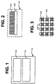
- Figure 1 is an illustration of a data storage device; and
- Figures 2 and 3 are illustrations of an array of nanotubes for the storage device of Figure 1.
-
- As shown in the drawings, the embodiment of the ultra-high density data storage device shown includes a storage medium and an array of nanotubes that function as electron sources. More rugged than Spindt emitters, the nanotubes are not damaged if they make contact with the storage medium. In addition, the nanotubes have a higher electron beam directionality than Spindt emitters. The higher directionality results in an electron beam having increased focus and accuracy, which allows bit size to be reduced. Reducing the bit size increases storage density and reduces storage cost. The higher directionality also allows the tips of the nanotubes to be spaced further from the storage medium. The nanotubes also have a lower material transfer rate than Spindt emitters. The lower transfer rate increases the effective life of the electron sources.
- Referring to Figure 1, the
storage medium 112 of thedata storage device 110 includes a storage layer. The storage layer may be made of a phase-change material such as a chalcogenide-based phase change material. Local areas of the storage layer can be reversibly changed between at least two states by application of focused radiation with appropriate time dependence of power amplitude. For instance, local areas may be changed between amorphous and crystalline states, or they may be changed between different crystalline states. The state of an area may be changed from crystalline to amorphous by heating the area with a high intensity energy beam, enough to melt the phase change material, and then quickly decreasing the intensity of the beam to quench the area. Quenching a phase-change material causes it to cool rapidly into an amorphous state without time to nucleate and grow crystalline grains. The state of an area may be changed from amorphous to crystalline by using an energy beam to heat the phase-change material at a temperature sufficient to allow nucleation and growth of crystalline grains. The different states represent different logic values. - The
storage device 110 also includes anarray 114 of nanotubes (e.g., carbon nanotubes, boron nitride nanotubes) that function as electron sources. Each nanotube emits an electron beam having appropriate time dependence of power amplitude to change a local storage area between amorphous and crystalline states or between different crystalline states. Tips of the nanotubes are proximate the storage layer. Electron optics may be used to focus the electron beams onto thestorage medium 112. - The
array 114 of nanotube electron sources may be stationary relative to thestorage medium 112. Thus, each nanotube tip may be stationed over a local storage area. In the alternative, micromovers (not shown) may be used to scan thearray 114 of nanotubes along the surface of the storage layer during read and write operations. Exemplary micromovers are described in assignee's U.S. patent no. 5,986,381. - Ruggedness and high directionality of the nanotubes allows a relaxation of the tolerances of the distance between the nanotube tips and the phase-change layer surface, the flatness of the phase-change layer surface, etc.
- Reference is now made to Figure 2, which shows the
array 114 ofnanotubes 212. Thenanotubes 212 may be single-walled or double-walled, and they are defined by their diameter, length, conductivity, and chirality or twist. Thenanotubes 212 are preferably elongated, as a higher aspect ratio provides better directionality. Thenanotubes 212 may have an aspect ratio greater than 10:1. Carbon nanotubes, for example, are fullerene-related structures that are long, thin tubes of carbon. The carbon nanotubes are tightly bonded, which results in a low material transfer rate with the phase-change layer of thestorage medium 112. - The
nanotubes 212 are formed on asubstrate 214. Photolithographic or other masking techniques may be used to define where on thesubstrate 214 thenanotubes 212 are grown. Although only a single column oftennanotubes 212 is shown in Figure 2, thearray 114 may have any number of rows and columns. Thearray 114 may include hundreds or thousands of thenanotubes 212. Spacing between thenanotubes 212 will depend in part upon whether a micromover is used to scan thearray 114 across the surface of the storage layer. - A non-photolithographic technique of fabricating
carbon nanotubes 114 on a silicon substrate is described in Nilsson et al., "Scanning field emission from patterned carbon nanotube films," Applied Physics Letters, Vol. 76, No. 15, April, 2000. Catalytic inks are "printed" as a pattern on the native oxide of the silicon substrate, and carbon nanotubes are grown. - Referring additionally to Figure 3, word and
bit lines nanotubes 212 are also formed on thesubstrate 214. Thenanotubes 212 may be addressed simultaneously or in a multiplexed manner during read and write operations. To select a nanotube to generate an electron beam during a read or write operation, a voltage is created between the selectednanotube 212 and thestorage medium 112. The word andbit lines nanotube 212. A reference potential is applied to thestorage medium 112, such that the selectednanotube 212 becomes a cathode and thestorage medium 112 becomes an anode. The conductivity of thenanotubes 212 can be changed and the potentials can be varied to obtain electron beams of a desired time dependence of amplitude. Thenanotubes 212 do not need an ultra-high vacuum to generate the electron beams. - Read and write operations may be performed as described in Gibson et al. U.S. Patent No. 5,557,596, except that nanotubes are used instead of Spindt emitters.
- The nanotube electron sources are not limited to use in data storage devices. For instance, the nanotube electron sources may be used as electron emitters in lithographic applications.
- Although a specific embodiment of the present invention has been described and illustrated, the present invention is not limited to the specific forms or arrangements of parts so described and illustrated.
- The disclosures in United States patent application No. 09/900,662 from which this application claims priority, and in the abstract accompanying this application are incorporated herein by reference.
Claims (8)
- A data storage device (110) including an array (114) of nanotubes (212) as electron sources.
- A device as in claim 1, wherein the nanotubes (212) are carbon-based.
- A device as in claim 1, wherein the nanotubes (212) are boron nitride-based.
- A device as in claim 1, 2 or 3, including a phase-change storage layer (112) proximate tips of the electron sources.
- A device as in any preceding claim, wherein each nanotube (212) is elongated.
- A device as in claim 5, wherein the nanotubes (212) have an aspect ratio greater than 10:1.
- A device as in any preceding claim, including word and bit lines (216,218) for addressing the nanotubes (212).
- A device as in any preceding claim, including a micromover for positioning the array.
Applications Claiming Priority (2)
| Application Number | Priority Date | Filing Date | Title |
|---|---|---|---|
| US900662 | 1986-08-27 | ||
| US09/900,662 US6928042B2 (en) | 2001-07-06 | 2001-07-06 | Data storage device including nanotube electron sources |
Publications (2)
| Publication Number | Publication Date |
|---|---|
| EP1274092A2 true EP1274092A2 (en) | 2003-01-08 |
| EP1274092A3 EP1274092A3 (en) | 2003-10-15 |
Family
ID=25412893
Family Applications (1)
| Application Number | Title | Priority Date | Filing Date |
|---|---|---|---|
| EP02254312A Withdrawn EP1274092A3 (en) | 2001-07-06 | 2002-06-20 | Data storage device with array of nanotubes as electron sources |
Country Status (4)
| Country | Link |
|---|---|
| US (2) | US6928042B2 (en) |
| EP (1) | EP1274092A3 (en) |
| JP (1) | JP2003094400A (en) |
| CN (1) | CN1396659A (en) |
Cited By (4)
| Publication number | Priority date | Publication date | Assignee | Title |
|---|---|---|---|---|
| FR2862156A1 (en) * | 2003-11-06 | 2005-05-13 | Commissariat Energie Atomique | Data recording device incorporating a micro-point with a conducting core of constant section, notably a carbon nanotube, for recording at high data storage densities |
| EP1744323A1 (en) * | 2005-07-14 | 2007-01-17 | Qimonda AG | Phase change memory cell having nanowire electrode |
| WO2007030483A2 (en) | 2005-09-06 | 2007-03-15 | Nantero, Inc. | Method and system of using nanotube fabrics as joule heating elements for memories and other applications |
| US7700934B2 (en) | 2004-09-27 | 2010-04-20 | Koninklijke Philips Electronics N.V. | Electric device with nanowires comprising a phase change material |
Families Citing this family (26)
| Publication number | Priority date | Publication date | Assignee | Title |
|---|---|---|---|---|
| US7260051B1 (en) * | 1998-12-18 | 2007-08-21 | Nanochip, Inc. | Molecular memory medium and molecular memory integrated circuit |
| US20020138301A1 (en) * | 2001-03-22 | 2002-09-26 | Thanos Karras | Integration of a portal into an application service provider data archive and/or web based viewer |
| US6982898B2 (en) | 2002-10-15 | 2006-01-03 | Nanochip, Inc. | Molecular memory integrated circuit utilizing non-vibrating cantilevers |
| US7233517B2 (en) * | 2002-10-15 | 2007-06-19 | Nanochip, Inc. | Atomic probes and media for high density data storage |
| WO2004075171A2 (en) * | 2003-02-14 | 2004-09-02 | Oakley William S | Data recording using carbon nanotube electron sources |
| WO2005067585A2 (en) * | 2003-07-03 | 2005-07-28 | William Oakley | Adaptive read and read-after-write for carbon nanotube recorders |
| US20060187802A1 (en) * | 2003-07-03 | 2006-08-24 | Oakley William S | Array of cnt heads |
| US20050243660A1 (en) * | 2004-04-16 | 2005-11-03 | Rust Thomas F | Methods for erasing bit cells in a high density data storage device |
| US7620632B2 (en) * | 2004-06-30 | 2009-11-17 | Skyler Technology, Inc. | Method and/or system for performing tree matching |
| CN1300839C (en) * | 2004-08-06 | 2007-02-14 | 中国科学院上海微系统与信息技术研究所 | Process for preparing nano electronic phase change storage |
| US20080204966A1 (en) * | 2004-09-21 | 2008-08-28 | The Johns Hopkins University | Controlled Transport and Assembly of Nanostructures |
| US7190539B1 (en) | 2004-12-29 | 2007-03-13 | Storage Technology Corporation | Magnetic recorder having carbon nanotubes embedded in anodic alumina for emitting electron beams to perform heat-assisted magnetic recording |
| US7463573B2 (en) * | 2005-06-24 | 2008-12-09 | Nanochip, Inc. | Patterned media for a high density data storage device |
| US20070041237A1 (en) * | 2005-07-08 | 2007-02-22 | Nanochip, Inc. | Media for writing highly resolved domains |
| US7367119B2 (en) * | 2005-06-24 | 2008-05-06 | Nanochip, Inc. | Method for forming a reinforced tip for a probe storage device |
| US20060291271A1 (en) * | 2005-06-24 | 2006-12-28 | Nanochip, Inc. | High density data storage devices having servo indicia formed in a patterned media |
| US7309630B2 (en) * | 2005-07-08 | 2007-12-18 | Nanochip, Inc. | Method for forming patterned media for a high density data storage device |
| US20070008865A1 (en) * | 2005-07-08 | 2007-01-11 | Nanochip, Inc. | High density data storage devices with polarity-dependent memory switching media |
| US20070008866A1 (en) * | 2005-07-08 | 2007-01-11 | Nanochip, Inc. | Methods for writing and reading in a polarity-dependent memory switch media |
| US20070008867A1 (en) * | 2005-07-08 | 2007-01-11 | Nanochip, Inc. | High density data storage devices with a lubricant layer comprised of a field of polymer chains |
| US20080001075A1 (en) * | 2006-06-15 | 2008-01-03 | Nanochip, Inc. | Memory stage for a probe storage device |
| US20080175033A1 (en) * | 2007-01-19 | 2008-07-24 | Nanochip, Inc. | Method and system for improving domain stability in a ferroelectric media |
| US20080233672A1 (en) * | 2007-03-20 | 2008-09-25 | Nanochip, Inc. | Method of integrating mems structures and cmos structures using oxide fusion bonding |
| CN101504948B (en) * | 2008-02-05 | 2011-04-06 | 财团法人工业技术研究院 | Hollow pen tip like structure, apparatus comprising the same, and manufacturing method therefor |
| WO2012128763A1 (en) * | 2011-03-23 | 2012-09-27 | Empire Technology Development Llc | Capacitor with parallel nanotubes |
| US10225082B2 (en) | 2016-07-26 | 2019-03-05 | International Business Machines Corporation | Carbon nanotube physical entropy source |
Citations (5)
| Publication number | Priority date | Publication date | Assignee | Title |
|---|---|---|---|---|
| US5557596A (en) * | 1995-03-20 | 1996-09-17 | Gibson; Gary | Ultra-high density storage device |
| EP0945884A1 (en) * | 1998-03-23 | 1999-09-29 | Nec Corporation | Field emission device using a boron nitride nanotube electron source |
| EP0951047A2 (en) * | 1998-03-27 | 1999-10-20 | Canon Kabushiki Kaisha | Nanostructure, electron emitting device, carbon nanotube device, and method of producing the same |
| US5986381A (en) * | 1997-03-14 | 1999-11-16 | Hewlett-Packard Company | Electrostatic actuator with spatially alternating voltage patterns |
| US6097138A (en) * | 1996-09-18 | 2000-08-01 | Kabushiki Kaisha Toshiba | Field emission cold-cathode device |
Family Cites Families (8)
| Publication number | Priority date | Publication date | Assignee | Title |
|---|---|---|---|---|
| DE4409850C2 (en) * | 1994-03-22 | 1999-05-12 | Fraunhofer Ges Forschung | Information storage unit |
| US6498349B1 (en) * | 1997-02-05 | 2002-12-24 | Ut-Battelle | Electrostatically focused addressable field emission array chips (AFEA's) for high-speed massively parallel maskless digital E-beam direct write lithography and scanning electron microscopy |
| JP3403635B2 (en) | 1998-03-26 | 2003-05-06 | 富士通株式会社 | Display device and method of driving the display device |
| US6518570B1 (en) * | 1998-04-03 | 2003-02-11 | Brookhaven Science Associates | Sensing mode atomic force microscope |
| DE69935422T2 (en) * | 1998-12-03 | 2007-11-29 | Daiken Chemical Co. Ltd. | SURFACE SIGNAL COMMAND PROBE OF ELECTRONIC DEVICE AND METHOD FOR THE PRODUCTION THEREOF |
| KR20010011136A (en) * | 1999-07-26 | 2001-02-15 | 정선종 | Structure of a triode-type field emitter using nanostructures and method for fabricating the same |
| US6519221B1 (en) * | 1999-11-12 | 2003-02-11 | Massachusetts Institute Of Technology | High-density data storage using atomic force microscope |
| US6542400B2 (en) * | 2001-03-27 | 2003-04-01 | Hewlett-Packard Development Company Lp | Molecular memory systems and methods |
-
2001
- 2001-07-06 US US09/900,662 patent/US6928042B2/en not_active Expired - Lifetime
-
2002
- 2002-06-20 EP EP02254312A patent/EP1274092A3/en not_active Withdrawn
- 2002-07-04 JP JP2002195692A patent/JP2003094400A/en active Pending
- 2002-07-05 CN CN02141131A patent/CN1396659A/en active Pending
-
2005
- 2005-05-25 US US11/136,882 patent/US7295503B2/en not_active Expired - Lifetime
Patent Citations (5)
| Publication number | Priority date | Publication date | Assignee | Title |
|---|---|---|---|---|
| US5557596A (en) * | 1995-03-20 | 1996-09-17 | Gibson; Gary | Ultra-high density storage device |
| US6097138A (en) * | 1996-09-18 | 2000-08-01 | Kabushiki Kaisha Toshiba | Field emission cold-cathode device |
| US5986381A (en) * | 1997-03-14 | 1999-11-16 | Hewlett-Packard Company | Electrostatic actuator with spatially alternating voltage patterns |
| EP0945884A1 (en) * | 1998-03-23 | 1999-09-29 | Nec Corporation | Field emission device using a boron nitride nanotube electron source |
| EP0951047A2 (en) * | 1998-03-27 | 1999-10-20 | Canon Kabushiki Kaisha | Nanostructure, electron emitting device, carbon nanotube device, and method of producing the same |
Non-Patent Citations (2)
| Title |
|---|
| MURAKAMI H ET AL: "FIELD EMISSION FROM WELL-ALIGNED, PATTERNED, CARBON NANOTUBE EMITTERS" APPLIED PHYSICS LETTERS, AMERICAN INSTITUTE OF PHYSICS. NEW YORK, US, vol. 76, no. 13, 27 March 2000 (2000-03-27), pages 1776-1778, XP000950557 ISSN: 0003-6951 * |
| RUECKES T ET AL: "CARBON NANOTUBE-BASED NONVOLATILE RANDOM ACCESS MEMORY FOR MOLECULAR COMPUTING" SCIENCE, AMERICAN ASSOCIATION FOR THE ADVANCEMENT OF SCIENCE,, US, vol. 289, no. 5476, July 2000 (2000-07), pages 94-97, XP000925696 ISSN: 0036-8075 * |
Cited By (11)
| Publication number | Priority date | Publication date | Assignee | Title |
|---|---|---|---|---|
| FR2862156A1 (en) * | 2003-11-06 | 2005-05-13 | Commissariat Energie Atomique | Data recording device incorporating a micro-point with a conducting core of constant section, notably a carbon nanotube, for recording at high data storage densities |
| WO2005048255A1 (en) * | 2003-11-06 | 2005-05-26 | Commissariat A L'energie Atomique | Data-recording device comprising conductive microtips and production method thereof |
| US7453789B2 (en) | 2003-11-06 | 2008-11-18 | Commissariat A L'energie Atomique | Data recording device with conducting microtips and production method thereof |
| US7700934B2 (en) | 2004-09-27 | 2010-04-20 | Koninklijke Philips Electronics N.V. | Electric device with nanowires comprising a phase change material |
| EP1744323A1 (en) * | 2005-07-14 | 2007-01-17 | Qimonda AG | Phase change memory cell having nanowire electrode |
| US7420199B2 (en) | 2005-07-14 | 2008-09-02 | Infineon Technologies Ag | Resistivity changing memory cell having nanowire electrode |
| WO2007030483A2 (en) | 2005-09-06 | 2007-03-15 | Nantero, Inc. | Method and system of using nanotube fabrics as joule heating elements for memories and other applications |
| EP1922743A2 (en) * | 2005-09-06 | 2008-05-21 | Nantero, Inc. | Method and system of using nanotube fabrics as joule heating elements for memories and other applications |
| EP1922743A4 (en) * | 2005-09-06 | 2008-10-29 | Nantero Inc | Method and system of using nanotube fabrics as joule heating elements for memories and other applications |
| AU2006287609B2 (en) * | 2005-09-06 | 2012-08-02 | Nantero, Inc. | Method and system of using nanotube fabrics as joule heating elements for memories and other applications |
| US8525143B2 (en) | 2005-09-06 | 2013-09-03 | Nantero Inc. | Method and system of using nanotube fabrics as joule heating elements for memories and other applications |
Also Published As
| Publication number | Publication date |
|---|---|
| EP1274092A3 (en) | 2003-10-15 |
| JP2003094400A (en) | 2003-04-03 |
| US7295503B2 (en) | 2007-11-13 |
| US6928042B2 (en) | 2005-08-09 |
| US20030007443A1 (en) | 2003-01-09 |
| US20050218322A1 (en) | 2005-10-06 |
| CN1396659A (en) | 2003-02-12 |
Similar Documents
| Publication | Publication Date | Title |
|---|---|---|
| US7295503B2 (en) | Data storage device including nanotube electron sources | |
| JP4972000B2 (en) | AFM type data storage device | |
| US7892063B2 (en) | Method of manufacturing tubular carbon molecule and tubular carbon molecule, method of manufacturing recording apparatus and recording apparatus, method of manufacturing field electron emission device and field electron emission device, and method of manufacturing display unit and display unit | |
| US6473388B1 (en) | Ultra-high density information storage device based on modulated cathodoconductivity | |
| JPH097240A (en) | Storage device | |
| US6735163B2 (en) | Ultra-high density storage device with resonant scanning micromover | |
| US6643248B2 (en) | Data storage device | |
| US6815875B2 (en) | Electron source having planar emission region and focusing structure | |
| US6911768B2 (en) | Tunneling emitter with nanohole openings | |
| JP2002326200A (en) | Method for passing current between scanned probe and recording medium | |
| US20030081532A1 (en) | Supplementary energy sources for atomic resolution storage memory devices | |
| US7057997B2 (en) | Class of electron beam based data storage devices and methods of use thereof | |
| US7459321B2 (en) | Method of storing a data bit in a fast-write alloy | |
| US6617597B2 (en) | Circuits and methods for electron-beam control | |
| US6930971B2 (en) | Ultra-high density storage device with electron beam steering | |
| JP4629314B2 (en) | Atomic resolution storage device | |
| US7355955B2 (en) | Nanoscale digital data storage device | |
| US20050040383A1 (en) | Data storage device | |
| Kuo et al. | An ultra-compact electron-beam column | |
| US20040218508A1 (en) | Data cluster erasure |
Legal Events
| Date | Code | Title | Description |
|---|---|---|---|
| PUAI | Public reference made under article 153(3) epc to a published international application that has entered the european phase |
Free format text: ORIGINAL CODE: 0009012 |
|
| AK | Designated contracting states |
Kind code of ref document: A2 Designated state(s): AT BE CH CY DE DK ES FI FR GB GR IE IT LI LU MC NL PT SE TR |
|
| AX | Request for extension of the european patent |
Free format text: AL;LT;LV;MK;RO;SI |
|
| PUAL | Search report despatched |
Free format text: ORIGINAL CODE: 0009013 |
|
| AK | Designated contracting states |
Kind code of ref document: A3 Designated state(s): AT BE CH CY DE DK ES FI FR GB GR IE IT LI LU MC NL PT SE TR |
|
| AX | Request for extension of the european patent |
Extension state: AL LT LV MK RO SI |
|
| 17P | Request for examination filed |
Effective date: 20040405 |
|
| AKX | Designation fees paid |
Designated state(s): DE GB |
|
| STAA | Information on the status of an ep patent application or granted ep patent |
Free format text: STATUS: THE APPLICATION IS DEEMED TO BE WITHDRAWN |
|
| 18D | Application deemed to be withdrawn |
Effective date: 20060221 |