EP1273320A1 - Apparatus for transcranial magnetic stimulation - Google Patents
Apparatus for transcranial magnetic stimulation Download PDFInfo
- Publication number
- EP1273320A1 EP1273320A1 EP01114823A EP01114823A EP1273320A1 EP 1273320 A1 EP1273320 A1 EP 1273320A1 EP 01114823 A EP01114823 A EP 01114823A EP 01114823 A EP01114823 A EP 01114823A EP 1273320 A1 EP1273320 A1 EP 1273320A1
- Authority
- EP
- European Patent Office
- Prior art keywords
- induction device
- brain
- head
- simulation model
- area
- Prior art date
- Legal status (The legal status is an assumption and is not a legal conclusion. Google has not performed a legal analysis and makes no representation as to the accuracy of the status listed.)
- Granted
Links
Images


Classifications
-
- A—HUMAN NECESSITIES
- A61—MEDICAL OR VETERINARY SCIENCE; HYGIENE
- A61N—ELECTROTHERAPY; MAGNETOTHERAPY; RADIATION THERAPY; ULTRASOUND THERAPY
- A61N2/00—Magnetotherapy
- A61N2/02—Magnetotherapy using magnetic fields produced by coils, including single turn loops or electromagnets
-
- A—HUMAN NECESSITIES
- A61—MEDICAL OR VETERINARY SCIENCE; HYGIENE
- A61B—DIAGNOSIS; SURGERY; IDENTIFICATION
- A61B5/00—Measuring for diagnostic purposes; Identification of persons
- A61B5/05—Detecting, measuring or recording for diagnosis by means of electric currents or magnetic fields; Measuring using microwaves or radio waves
- A61B5/055—Detecting, measuring or recording for diagnosis by means of electric currents or magnetic fields; Measuring using microwaves or radio waves involving electronic [EMR] or nuclear [NMR] magnetic resonance, e.g. magnetic resonance imaging
-
- A—HUMAN NECESSITIES
- A61—MEDICAL OR VETERINARY SCIENCE; HYGIENE
- A61B—DIAGNOSIS; SURGERY; IDENTIFICATION
- A61B5/00—Measuring for diagnostic purposes; Identification of persons
- A61B5/24—Detecting, measuring or recording bioelectric or biomagnetic signals of the body or parts thereof
- A61B5/316—Modalities, i.e. specific diagnostic methods
- A61B5/369—Electroencephalography [EEG]
- A61B5/377—Electroencephalography [EEG] using evoked responses
Definitions
- the present invention relates to methods and apparatus for a transcranial magnetic stimulation, in particular for non-invasive localization of specific areas of a brain, such as so-called primary brain areas.
- This can be used for For example, the brain functions are mapped, ie assigned to certain brain areas.
- a method is known in which a stereotactic transcranial magnetic stimulation (TMS) used for preoperative functional mapping of the motor cortex becomes.
- TMS stereotactic transcranial magnetic stimulation
- the head of a patient is thereby firmly and immovably connected to a headrest, wherein a pivot arm is provided, to which an 8-shaped coil is attached is that the arm tip is below the coil intersection.
- the arm is aligned, that the point lying under the intersection of the two coils to a certain Range shows in which a current is to be induced.
- a non-invasive localization of primary Brain areas for example, the spatial structure of the brain by means of a nuclear magnetic resonance (MRI), a computed tomography (CT) or a other suitable procedures.
- An induction device which for Generating necessary for the stimulation magnetic fields is used, according to the invention examined before starting the stimulation. It is calculated, for example, which Magnetic field from the induction device at certain current flowing through is generated, in particular where the magnetic field generated by the induction device is the largest, so for example has the largest field strength.
- an optical accurate examination of the coil winding or coil windings of the induction device be made from these coil windings of the area or Calculated point of the maximum generated by the induction device magnetic field can be.
- the induction device may also be X-rayed or by others appropriate procedures are studied to provide an accurate analysis of the current conduction of the induction device perform.
- a measurement be with which the spatial area or point of the largest by the induction device generated magnetic field in relation to the induction device can be determined can.
- this assay result can be a simulation model the induction device are created so that this relative to the Gehim to be examined can be arranged so that a desired area of the brain by a in the Induction device can be stimulated flowing current. It can thus be a spatial as narrow as possible strong magnetic field focused on a small area of the brain become.
- a simulation model of the generated from the recording of the spatial structure of the Kopfes data can be used to improve the simulation model.
- the electrical or magnetic generated by the induction device Field by appropriate positioning of the induction device relatively accurately on a be focused on the specific point of the brain, because the one different conductivity Having overlying layers above the brain how different dielectrics act, the have a decisive influence on the focusing of the field on the brain.
- the two methods of analysis and simulation of the induction device described above and the modeling of the head can be done separately or in combination used to focus the field generated by the induction device continue to improve.
- transcranial magnetic stimulation TMS
- TMS transcranial magnetic stimulation
- the however, methods of the invention may also be used to study or cure others Functional disorders of the brain are used, such as for diagnosing epilepsy or the diagnosis of Parkinson's disease.
- Functional disorders of the brain such as for diagnosing epilepsy or the diagnosis of Parkinson's disease.
- the modeling of the head takes place by forming a finite multi-shell model, where, for example, the calculation of electric and / or magnetic Feldem can be done with finite element methods and the individual shells advantageous for example as nested spherical or ellipsoidal shells with adjustable Thickness can be modeled, which may be arranged concentrically, for example.
- a subdivision into three shells is advantageous, wherein by the respective Shells simulating the scalp, skull bones and brain surface from outside to inside become.
- These three different head areas have different electrical and magnetic properties, so that, for example, a modeling of a head by three shells with, for example, different dielectric constant and / or different Conductance can deliver pretty good results when used for electrical or magnetic parameters of the individual shells used values as close as possible for tests determined or calculated values.
- the shell model becomes advantageous still depending on a completed recording of the spatial structure of a modified head, for example, by stretching and / or distortion or displacement of individual shells as accurate as possible adaptation of the shell model is made to the geometry of a head to be examined.
- the referencing and tracking of people and / or instruments is known in the art and will not be described here described.
- a matching between induction device and head is made, so the relative spatial position between induction device and head as precisely as possible to be able to determine.
- the use of markers has the advantage that one examined Person does not need to be stationarily positioned, but that even when a person is free in the Space-moving person made a precise stimulation of certain brain areas can be.
- an induction device for example, a single coil consisting of one or multiple windings or a combination of coils are used. Especially advantageous an induction device is used in which two in-plane lie Coils are adjacent to each other, so that the coils have approximately the shape of an "8".
- the stimulation of a brain area is preferably carried out by applied to the induction device electrical pulses, which have a rise time in the range of one microsecond to one millisecond and a duration of 10 to 1000 microseconds. there The individual impulses can be created with a periodic pattern.
- a visual display of the determined by a recording spatial Structure of the brain surface advantageous with a display of the simulated stimulation area at a current position of the induction device.
- an operator for example, by tilting the side Induction device and / or moving the induction device upside down or away from the head change the position and size of the stimulation area, wherein a As small as possible focus is sought to achieve the highest possible spatial resolution in the localization of certain brain areas.
- the positioning of the induction device takes place relative to the head automatically, wherein the induction device by, for example, one with multiple degrees of freedom movable robot arm is positioned so that a variety of points on the surface of the brain are stimulated with as small a focus as possible.
- the movable robot arm can be firmly attached to the head. It can, for example from a pattern recognition software suitable stimulation points on the brain surface are selected and / or stimulation points specified by an operator which are then automatically approached by the robot arm so that the positioned Induction device stimulates the smallest possible area of the brain surface.
- the simulation model of the induction device and / or the head are examples of the simulation model of the induction device and / or the head.
- a device for stimulating certain Areas of a brain proposed, with an induction device provided which is firmly associated with markers, preferably passive markers.
- markers preferably passive markers.
- Marking inducing device can be inventively easily and precisely positioned be to a particular area of the brain with the smallest possible focus point to stimulate.
- Markers in a fixed spatial arrangement are also advantageous on the head to be examined attached, which as well as connected to the induction device marker by a position detection device can be detected.
- a simulation device is preferred provided with which of the to be stimulated by the induction device Stimulation area in the brain can be determined, whereby to simulate the Stimulation area as described above, a model of the induction device and / or of the head can be used.
- a display device for displaying the relative position between the induction device and brain or to display the producible by the induction device Stimulation field provided on the brain, which allow an operator to position the induction device as precisely as possible relative to the brain before a stimulation pulse is triggered.
- the device according to the invention has a device for automatic Positioning the induction device relative to the brain, such as a robotic arm, which is movable with several degrees of freedom, so for example one or has several joints, so that the induction device, for example, towards the head or can be moved away from the head or tilted with respect to the head surface, so a stimulation region on the brain that can be generated by the induction device to be as small as possible.
- a device for automatic Positioning the induction device relative to the brain such as a robotic arm, which is movable with several degrees of freedom, so for example one or has several joints, so that the induction device, for example, towards the head or can be moved away from the head or tilted with respect to the head surface, so a stimulation region on the brain that can be generated by the induction device to be as small as possible.
- Fig. 1 shows schematically a three-shell model of a head according to the invention, wherein the outer shell I sculpted the scalp under which modeled by the outer shell I. Scalp is the second shell II, which models the skull bone.
- the interior of the three-shell model is formed by the brain or the brain surface III.
- One Current in the induction device 1 shown schematically by a coil causes this schematically shown magnetic field, which emanates from the induction device 1 and passes through the scalp and through the skull bone to the brain, each modeled through the three shells I, II and III, a schematically shown electric field which causes an annular flow of current, creating a certain area of the brain is stimulated.
- the modeling of scalp, skull and brain by two outer shells I and II surrounding the modeled brain III it is that the induction device 1 at a certain point at a certain distance positioned by the brain and at a certain tilt angle relative to the surface of the brain This can be done by the magnetic field of the induction device on the brain surface to concentrate induced electric field in as small an area as possible, to get as strong a focus as possible.
- Fig. 2a shows schematically a model, which so far for modeling an electric field was used by two in a plane adjacent coils, which form the induction device 1 was generated. However, it was not taken into account that due to the curvature of the head through the induction device 1 on the Brain surface induced electric field by curved shells with different Conductivity and dielectric constant is affected.
- Fig. 2b shows schematically the outer shell I of the inventive three-shell model with overlying induction device 1, whereby a more accurate modeling of a Head, thereby enabling the exact focusing of an induced electric field becomes.
- Fig. 3 shows schematically a coil having a plurality of windings, which for example can be used as a subelement of the induction device 1 shown in Fig. 2b.
- the coil is not by concentric nested conductor formed, but by a single spirally wound conductor element, whereby a slight asymmetry of the magnetic generated by such a spiral conductor element Field is present.
- an investigation of the actually used induction device to get a good simulation model The assumption that, for example, with an 8-shaped coil, the maximum of the generated magnetic field is below the point of intersection, due to the asymmetry of a coil winding generally not and leads to poor results in TMS.
- FIG. 4a shows in comparison to the field generated by only one coil. It can easily be recognized be that better focusing with high field strength advantageous by a Double coil arrangement can be realized.
- the one shown in Fig. 4a by a single Coil generated magnetic field strength distribution is due to the annular maximum not as well focusable on a small area as that produced by a double coil magnetic field of Fig. 4b with a clearly pointed maximum.
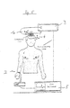
- Fig. 5 shows schematically a device according to the invention for the stimulation of certain areas a brain, wherein an induction device connected to a reference star 1a 1 is connected to a drive device 3, which generates pulses to the brain the person shown, to which a further reference star 4 is fixed, a stimulate specific area.
- a motor brain area is stimulated, so can by means of a surface electrode 2, which, for example, on the arm of the person is attached, measured by an electromyography (EMG) measurement of an excitation pulse be as exemplified on the measuring device 5.
- EMG electromyography
- Through a feedback from the measuring device 5 to the drive device 4 can automatically as accurate as possible Localization of the motor area done, for example, the induction device 1 automatically by means of a robot arm in suitable for one or more stimulations Position is brought.
- Fig. 6 shows schematically the flow diagram of an embodiment of the invention Process.
- nuclear magnetic resonance (MRI) is the spatial Structure of a head with brain added.
- the data obtained in step 10 will be in Step 11 used to generate a simulation model of the recorded head, for example, as described above, the scalp, the cranial bone, and the brain are modeled as three regions I, II and III, each having a characteristic dielectric constant and have a characteristic conductance.
- the head is with one Reference star 4 connected, as shown in Fig. 5, whereby its spatial position at any time can be easily detected (tracking).
- step 13 the induction device 1 used is modeled, wherein for modeling Data can be used, which from a detailed examination of the spatial Structure obtained by conductors or coils contained in the induction device were so that a magnetic field generated by the induction device relative accurately calculated and simulated. Furthermore, the induction device can also by evaluation of measurements in the magnetic field generated by the induction device Field can be modeled. By modeling, a focusing area of a actually used induction device can be determined relatively accurately.
- the induction device is connected, as shown in Fig. 5, with a reference star 1a, whereby the Induction device 1 as well as the head connected to a reference star 4 tracked can be.
- step 15 a matching of the coordinates of the head and thus the spatial location of the structure of the brain obtained by MRI with the coordinates of Induction device made, reducing the relative spatial position of the induction device to the spatial structure of the head determined by magnetic resonance imaging, especially the brain can be obtained.
- step 16 positioning of the induction device at the head, the modeling data of the induction device and the modeling data of the head to be used at a current flow through the induction device to simulate generated induction area on the brain. Is the positioning done so that in the simulation the smallest possible area of the brain is stimulated by the induction device, so in step 17, the stimulation carried out by a simulation previously determined area.
- An observer can Now determine what a person shows for specific reactions when that particular area stimulated, with the help of these reactions, such as the twitching of a Muscles, disturbance of speech behavior or the like can be determined whether the stimulated
- the brain area has a certain functionality. Will this process the Repositioning and stimulating in a variety of areas of the brain of steps 16 and 17, a mapping of brain functions can be made in particular localizing the primary brain areas of the person being examined can be.
- the desired induced electric field using the simulation models are recalculated again, with respect, for example the induction device up to seven degrees of freedom (three for translation, three for rotation and one for coil current) are to be considered.
- Fig. 7 shows in the upper two halves of the picture the structure of a brain based on Nuclear magnetic resonance data obtained from two different angles.
- the underlying both pictures show the relative position of the induction device to the brain, which in response to displayed control signals to a position suitable for stimulation can be brought.
Abstract
Description
Die vorliegende Erfindung bezieht sich auf Verfahren und eine Vorrichtung für eine transcraniale magnetische Stimulation, insbesondere zur nicht-invasiven Lokalisation bestimmter Bereiche eines Gehirns, wie zum Beispiel sogenannter primärer Hirnareale. Damit können zum Beispiel die Hirnfunktionen kartiert, also bestimmten Hirnbereichen zugeordnet werden.The present invention relates to methods and apparatus for a transcranial magnetic stimulation, in particular for non-invasive localization of specific areas of a brain, such as so-called primary brain areas. This can be used for For example, the brain functions are mapped, ie assigned to certain brain areas.
In verschiedenen medizinischen Bereichen, wie zum Beispiel der Neurologie, der Psychiatrie oder der Gehirn-Chirurgie ist es wünschenswert bestimmte funktionale Bereiche des Gehirns lokalisieren zu können, um Hirnfunktionen zu kartieren. Soll zum Beispiel durch einen chirurgischen Eingriff ein Hirntumor entfernt werden, so sollte der Tumor soweit wie möglich entfernt werden, wobei jedoch sogenannte primäre Hirnareale, welche bezüglich der Motorik, Sensorik, der Sprache oder den visuellen Fähigkeiten einer Person eine entscheidende Rolle spielen, nach Möglichkeit nicht verletzt werden sollen. Diese Bereiche sollten bei einem chirurgischen Eingriff wenn möglich gar nicht oder nur in äußerst geringem Umfang verletzt werden.In various medical fields, such as neurology, psychiatry or brain surgery, it is desirable to have certain functional areas of the brain to be able to locate in order to map brain functions. For example, by a surgical To get a brain tumor removed, the tumor should be as far as possible removed, but so-called primary brain areas, which in terms of motor skills, Sensory, language or visual skills of a person a crucial role play, if possible should not be hurt. These areas should be at a surgical Intervention if possible not at all or injured only to a very small extent become.
Das Auffinden solcher besonderen Hirnbereiche wurde nach einem bekannten direkten Verfahren intra-operativ durchgeführt, wobei mittels Elektroden eine direkte cortikale Stimulation (DCS) an einem geöffneten Schädel erfolgte. Dabei wurde eine Elektrode in einen bestimmten Bereich des Gehirns eingebracht und ein elektrischer Impuls angelegt, wobei die auf den elektrischen Impuls folgende Reaktion der untersuchten Person, zum Beispiel das Zucken eines Muskels oder das Wahrnehmen von visuellen Eindrücken beobachtet wurde. Die durch die direkte cortikale Stimulation aufgefundenen besonderen Hirnbereiche wurden mittels aufgelegter kleiner Plättchen markiert, welche für einen Chirurgen bei einer nachfolgenden Gehirnoperation eine Orientierungshilfe bezüglich der möglichst nicht zu verletzenden Hirnbereiche darstellten. Die direkte cortikale Stimulation stellt bis zum heutigen Tag das präziseste Verfahren zur Kartierung von Hirnfunktionen dar und ermöglicht eine Genauigkeit bei der Auffindung bestimmter Hirnareale im Bereich von wenigen Millimetern. Jedoch kann dieses Verfahren nur intra-operativ durchgeführt werden, wobei die untersuchte Person bei vollem Bewusstsein sein muss. Dies kann bei der Anwendung dieses Verfahrens jedoch zu Problemen führen, da dieser Zustand für die untersuchte Person unangenehm ist und die Person, falls es zu Komplikationen kommen sollte, aufgrund der geöffneten Schädeldecke nicht einfach hingelegt und ruhig gestellt werden kann.The discovery of such special brain areas was done by a known direct method performed intraoperatively, using direct cortical stimulation by means of electrodes (DCS) on an open skull. It was an electrode in a specific Introduced brain area and created an electrical impulse, the on the electrical impulse following reaction of the examined person, for example the twitching of a muscle or the perception of visual impressions was observed. By The direct cortical stimulation found special areas of the brain were applied by means of Small platelets marked for a surgeon in a subsequent brain operation an orientation aid with regard to the brain areas, which should not be damaged if possible showed. Direct cortical stimulation remains the most accurate to date Method for mapping brain functions and enables accuracy in the Detection of certain brain areas in the range of a few millimeters. However, this can Procedure should only be performed intra-operatively, with the examined person at full Awareness must be. However, this can be a problem when using this method cause this condition is unpleasant for the person being examined and the person if complications should occur, not easy due to the open skullcap put down and can be made quiet.
Es sind weiterhin verschiedene indirekte Verfahren zur Kartierung von Hirnfunktionen bekannt, mit welchen jedoch nur eine erheblich geringere Genauigkeit beim Auffinden spezifischer Hirnareale erreicht werden kann. So muss zum Beispiel bei der funktionellen Kernspintomographie (fMRI) eine untersuchte Person bestimmte Aktionen wie zum Beispiel eine Handbewegung ausführen, welche die Durchblutung der diesen Aktionen zugeordneten Hirnbereichen fördert. Diese Veränderung der Durchblutung bestimmter Hirnbereiche kann aufgrund der Entkopplung von Durchblutung und Sauerstoffverbrauch während der neuronalen Aktivität gemessen werden, da hierdurch eine Hyperoxygenierung und damit ein Abfall der Konzentration des paramagnetischen Deoxy-Hämoglobins (BOLD-Effekt) auftritt, was dann als sogenanntes "endogenes Kontrastmittel" mittels geeigneter Sequenzen mit Kernspintomographie gemessen werden kann. Jedoch ist dieses Verfahren wie oben erwähnt, relativ ungenau und liefert nur eine räumliche Auflösung im Bereich von etwa 0,5 bis 1,0 cm.Various indirect methods of mapping brain functions are also known. with which, however, only a considerably lower accuracy in finding specific Brain areas can be achieved. For example, in functional magnetic resonance imaging (fMRI) an examined person has certain actions such as a Hand movement, which is the circulation of the brain areas associated with these actions promotes. This change in the circulation of certain brain areas may be due to the decoupling of blood flow and oxygen consumption during the neural Activity can be measured, as this hyperoxygenation and thus a drop in the Concentration of paramagnetic deoxyhemoglobin (BOLD effect) occurs, what then as so-called "endogenous contrast agent" by means of suitable sequences with magnetic resonance imaging can be measured. However, as mentioned above, this method is relatively inaccurate and only provides a spatial resolution in the range of about 0.5 to 1.0 cm.
Aus Neurosurgery 1992-1998, December 1997, Volume 41, Number 6, 1319 "Stereotactic Transcranial Magnetic Stimulation: Correlation with Direct Electrical Cortical Stimulation" ist ein Verfahren bekannt, bei welchem eine stereotaktische transcraniale magnetische Stimulation (TMS) für das präoperative funktionale Mapping des motorischen Cortex verwendet wird. Der Kopf eines Patienten wird dabei fest und unbeweglich mit einer Kopflehne verbunden, wobei eine Schwenkarm vorgesehen ist, an welchem eine 8-förmige Spule so angebracht ist, dass die Armspitze unter dem Spulenschnittpunkt liegt. Der Arm wird dabei so ausgerichtet, dass die unter dem Schnittpunkt der beiden Spulen liegenden Spitze auf einen bestimmten Bereich zeigt, in welchem ein Strom induziert werden soll.From Neurosurgery 1992-1998, December 1997, Volume 41, Number 6, 1319 "Stereotactic Transcranial Magnetic Stimulation: Correlation with Direct Electrical Cortical Stimulation " a method is known in which a stereotactic transcranial magnetic stimulation (TMS) used for preoperative functional mapping of the motor cortex becomes. The head of a patient is thereby firmly and immovably connected to a headrest, wherein a pivot arm is provided, to which an 8-shaped coil is attached is that the arm tip is below the coil intersection. The arm is aligned, that the point lying under the intersection of the two coils to a certain Range shows in which a current is to be induced.
Es ist eine Aufgabe der vorliegenden Erfindung Verfahren und eine Vorrichtung zur Stimulation bestimmter Bereiche eines Gehirns vorzuschlagen, mit welchen die Anwendung vereinfacht und die räumliche Genauigkeit der Stimulation und damit der Lokalisation bestimmter Hirnbereiche verbessert werden kann.It is an object of the present invention method and apparatus for stimulation to suggest certain areas of a brain that simplify the application and the spatial accuracy of the stimulation and thus the localization of certain Brain areas can be improved.
Diese Aufgabe wird mit den Gegenständen der unabhängigen Ansprüche gelöst. Vorteilhafte Ausführungsformen ergeben sich aus den Unteransprüchen.This object is achieved with the objects of the independent claims. advantageous Embodiments emerge from the subclaims.
Gemäß einem ersten Aspekt der Erfindung wird bei einem Verfahren zur Stimulation bestimmter Bereiche eines Gehirns, um zum Beispiel eine nicht-invasive Lokalisation von primären Hirnarealen vornehmen zu können, die räumliche Struktur des Gehirns zum Beispiel mittels eines Kernspinresonanzverfahrens (MRI), einer Computertomographie (CT) oder einem anderen geeigneten Verfahren aufgenommen. Eine Induktionsvorrichtung, welche zum Erzeugen von für die Stimulation notwendigen Magnetfeldern verwendet wird, wird erfindungsgemäß vor Beginn der Stimulation untersucht. Dabei wird zum Beispiel berechnet, welches Magnetfeld von der Induktionsvorrichtung bei bestimmten hindurchfließenden Strömen erzeugt wird, insbesondere wo das von der Induktionsvorrichtung erzeugte magnetische Feld am größten ist, also zum Beispiel die größte Feldstärke aufweist. Hierzu kann zum Beispiel eine optische genaue Untersuchung der Spulenwicklung bzw. Spulenwicklungen der Induktionsvorrichtung vorgenommen werden, wobei aus diesen Spulenwicklungen der Bereich bzw. Punkt des maximalen durch die Induktionsvorrichtung erzeugbaren Magnetfeldes berechnet werden kann. Die Induktionsvorrichtung kann zum Beispiel auch geröntgt oder durch andere geeignete Verfahren untersucht werden, um eine genaue Analyse der Stromführung der Induktionsvorrichtung durchzuführen. Alternativ oder ergänzend zur Berechnung des durch die Induktionsvorrichtung erzeugbaren Magnetfeldes kann auch eine Messung vorgenommen werden, mit welcher der räumliche Bereich bzw. Punkt des größten durch die Induktionsvorrichtung erzeugbaren Magnetfeldes in Relation zur Induktionsvorrichtung ermittelt werden kann. Allgemein soll erfindungsgemäß eine Induktionsvorrichtung vor der Verwendung zur Stimulation bzw. Simulation zur Stimulation bestimmter Bereiche eines Gehirns untersucht bzw. analysiert werden, um zu ermitteln, in welchem räumlichen Lageverhältnis zur Induktionsvorrichtung der Bereich bzw. Punkt liegt, an welchem durch die Spule das maximale magnetische bzw. durch das magnetische Feld das maximal induzierte elektrische Feld erzeugt wird. Unter Verwendung dieses Untersuchungsergebnisses kann ein Simulationsmodell der Induktionsvorrichtung erstellt werden, so dass diese relativ zum zu untersuchenden Gehim so angeordnet werden kann, dass ein gewünschter Bereich des Gehirns durch einen in der Induktionsvorrichtung fließenden Strom stimuliert werden kann. Es kann somit ein räumlich möglichst eng begrenztes starkes Magnetfeld auf einen kleinen Bereich des Gehirns fokussiert werden.According to a first aspect of the invention, in a method for stimulating certain Areas of a brain, for example, a non-invasive localization of primary Brain areas, for example, the spatial structure of the brain by means of a nuclear magnetic resonance (MRI), a computed tomography (CT) or a other suitable procedures. An induction device, which for Generating necessary for the stimulation magnetic fields is used, according to the invention examined before starting the stimulation. It is calculated, for example, which Magnetic field from the induction device at certain current flowing through is generated, in particular where the magnetic field generated by the induction device is the largest, so for example has the largest field strength. For this purpose, for example an optical accurate examination of the coil winding or coil windings of the induction device be made from these coil windings of the area or Calculated point of the maximum generated by the induction device magnetic field can be. For example, the induction device may also be X-rayed or by others appropriate procedures are studied to provide an accurate analysis of the current conduction of the induction device perform. Alternatively or in addition to the calculation of the by the Induced magnetic field can also be made a measurement be, with which the spatial area or point of the largest by the induction device generated magnetic field in relation to the induction device can be determined can. In general, according to the invention, an induction device before use for Stimulation or simulation to stimulate specific areas of a brain examined or analyzed in order to determine the spatial positional relationship to the induction device the area or point is at which through the coil the maximum magnetic or generated by the magnetic field, the maximum induced electric field becomes. Using this assay result can be a simulation model the induction device are created so that this relative to the Gehim to be examined can be arranged so that a desired area of the brain by a in the Induction device can be stimulated flowing current. It can thus be a spatial as narrow as possible strong magnetic field focused on a small area of the brain become.
Gemäß einem weiteren Aspekt der vorliegenden Erfindung wird ein Simulationsmodell des zu untersuchenden Kopfes erzeugt, wobei die aus der Aufnahme der räumlichen Struktur des Kopfes ermittelten Daten zur Verbesserung des Simulationsmodells verwendet werden können. Dadurch kann das durch die Induktionsvorrichtung erzeugte elektrische bzw. magnetische Feld durch geeignete Positionierung der Induktionsvorrichtung relativ genau auf einem bestimmten Punkt des Gehirns fokussiert werden, da die eine unterschiedliche Leitfähigkeit aufweisenden über dem Gehirn liegenden Schichten wie verschiedene Dielektrika wirken, die einen entscheidenden Einfluss auf die Fokussierung des Feldes auf dem Gehirn haben.According to another aspect of the present invention, a simulation model of the generated from the recording of the spatial structure of the Kopfes data can be used to improve the simulation model. As a result, the electrical or magnetic generated by the induction device Field by appropriate positioning of the induction device relatively accurately on a be focused on the specific point of the brain, because the one different conductivity Having overlying layers above the brain how different dielectrics act, the have a decisive influence on the focusing of the field on the brain.
Die beiden oben beschriebenen Verfahren der Analyse und Simulation der Induktionsvorrichtung und der Modellierung des Kopfes können getrennt voneinander oder in Kombination eingesetzt werden, um die Fokussierung des durch die Induktionsvorrichtung erzeugten Feldes weiter zu verbessern.The two methods of analysis and simulation of the induction device described above and the modeling of the head can be done separately or in combination used to focus the field generated by the induction device continue to improve.
Mit den erfindungsgemäßen Verfahren kann die transcraniale magnetische Stimulation (TMS) verbessert, insbesondere präzisiert werden, was eine präzise nicht-invasive Lokalisation bestimmter Gehirnbereiche, zum Beispiel der oben erwähnten primären Hirnareale ermöglicht, wodurch zum Beispiel die präoperative chirurgische Planung verbessert werden kann. Die erfindungsgemäßen Verfahren können jedoch auch zur Untersuchung oder Heilung anderer Funktionsstörungen des Gehirns eingesetzt werden, wie zum Beispiel zum Diagnostizieren einer Epilepsie oder der Diagnose der Parkinsonschen Krankheit. Unter Verwendung der erfindungsgemäßen Verfahren ist es möglich durch ein indirektes Verfahren eine genaue Kartierung von Hirnfunktionen vorzunehmen, ohne den Schädel einer Person öffnen zu müssen, um direkt auf das Gehirn zuzugreifen.With the methods according to the invention, transcranial magnetic stimulation (TMS) be improved, in particular, be specified, allowing a precise non-invasive localization of certain Brain areas, for example the above-mentioned primary brain areas, whereby, for example, the preoperative surgical planning can be improved. The however, methods of the invention may also be used to study or cure others Functional disorders of the brain are used, such as for diagnosing epilepsy or the diagnosis of Parkinson's disease. Using the invention Method, it is possible by an indirect method an accurate mapping of brain functions without having to open a person's skull to to access the brain directly.
Vorteilhaft erfolgt die Modellierung des Kopfes durch Bildung eines finiten Mehr-Schalen-Modells, wobei zum Beispiel die Berechnung von elektrischen und/oder magnetischen Feldem mit Finite-Elemente-Methoden durchgeführt werden kann und die einzelnen Schalen vorteilhaft zum Beispiel als ineinanderliegende Kugel- oder Ellipsoidschalen mit einstellbarer Dicke modelliert werden können, welche zum Beispiel konzentrisch angeordnet sein können. Insbesondere ist eine Unterteilung in drei Schalen von Vorteil, wobei durch die jeweiligen Schalen von außen nach innen die Kopfhaut, die Schädelknochen und die Hirnoberfläche simuliert werden. Diese drei verschiedenen Kopfbereiche weisen unterschiedliche elektrische und magnetische Eigenschaften auf, so dass zum Beispiel eine Modellierung eines Kopfes durch drei Schalen mit zum Beispiel unterschiedlicher Dielektrizitätskonstante und/oder unterschiedlicher Leitfähigkeit recht gute Ergebnisse liefern kann, wenn die für die elektrischen bzw. magnetischen Parameter der einzelnen Schalen verwendeten Werte möglichst nahe an bei Versuchen ermittelten oder errechneten Werten liegen. Vorteilhaft wird das Schalenmodell noch in Abhängigkeit von einer durchgeführten Aufnahme der räumlichen Struktur eines zu untersuchenden Kopfes modifiziert, wobei zum Beispiel durch Streckung und/oder Verzerrung bzw. Verschiebung einzelner Schalen eine möglichst genaue Anpassung des Schalenmodells an die Geometrie eines zu untersuchenden Kopfes vorgenommen wird.Advantageously, the modeling of the head takes place by forming a finite multi-shell model, where, for example, the calculation of electric and / or magnetic Feldem can be done with finite element methods and the individual shells advantageous for example as nested spherical or ellipsoidal shells with adjustable Thickness can be modeled, which may be arranged concentrically, for example. In particular, a subdivision into three shells is advantageous, wherein by the respective Shells simulating the scalp, skull bones and brain surface from outside to inside become. These three different head areas have different electrical and magnetic properties, so that, for example, a modeling of a head by three shells with, for example, different dielectric constant and / or different Conductance can deliver pretty good results when used for electrical or magnetic parameters of the individual shells used values as close as possible for tests determined or calculated values. The shell model becomes advantageous still depending on a completed recording of the spatial structure of a modified head, for example, by stretching and / or distortion or displacement of individual shells as accurate as possible adaptation of the shell model is made to the geometry of a head to be examined.
Bevorzugt werden an dem untersuchten Kopf und/oder an der Induktionsvorrichtung Marker, besonders bevorzugt passive Marker angebracht, um eine Tracking der Induktionsvorrichtung und/oder des Kopfes vornehmen zu können. Die Referenzierung und das Tracking von Personen und/oder Instrumenten ist aus dem Stand der Technik bekannt und wird hier nicht näher beschrieben. Es wird ein Matching zwischen Induktionsvorrichtung und Kopf vorgenommen, um so die relative räumliche Lage zwischen Induktionsvorrichtung und Kopf möglichst präzise bestimmen zu können. Die Verwendung von Markern hat den Vorteil, dass eine untersuchte Person nicht ortsfest positioniert werden muss, sondern dass auch bei einer sich frei im Raum bewegenden Person eine präzise Stimulation bestimmter Hirnbereiche vorgenommen werden kann.Preference is given to the examined head and / or to the induction device markers, particularly preferred passive markers attached to a tracking of the induction device and / or the head to make. The referencing and tracking of people and / or instruments is known in the art and will not be described here described. A matching between induction device and head is made, so the relative spatial position between induction device and head as precisely as possible to be able to determine. The use of markers has the advantage that one examined Person does not need to be stationarily positioned, but that even when a person is free in the Space-moving person made a precise stimulation of certain brain areas can be.
Als Induktionsvorrichtung kann zum Beispiel eine einzelne Spule bestehend aus einer oder mehreren Wicklungen oder eine Kombination aus Spulen verwendet werden. Besonders vorteilhaft wird eine Induktionsvorrichtung verwendet, bei welcher zwei in einer Ebene liegenden Spulen zueinander benachbart sind, so dass die Spulen in etwa die Gestalt einer "8" aufweisen. As an induction device, for example, a single coil consisting of one or multiple windings or a combination of coils are used. Especially advantageous an induction device is used in which two in-plane lie Coils are adjacent to each other, so that the coils have approximately the shape of an "8".
Die Stimulation eines Hirnareals erfolgt bevorzugt durch an die Induktionsvorrichtung angelegte elektrische Impulse, welche eine Anstiegszeit im Bereich von einer Mikrosekunde bis einer Millisekunde und eine Dauer von 10 bis 1000 Mikrosekunden haben können. Dabei können die einzelnen Impulse mit einem periodischen Muster angelegt werden.The stimulation of a brain area is preferably carried out by applied to the induction device electrical pulses, which have a rise time in the range of one microsecond to one millisecond and a duration of 10 to 1000 microseconds. there The individual impulses can be created with a periodic pattern.
Bevorzugt erfolgt eine optische Anzeige der durch eine Aufnahme ermittelten räumlichen Struktur der Hirnoberfläche, vorteilhaft mit einer Anzeige des simulierten Stimulationsbereiches bei einer momentanen Lage der Induktionsvorrichtung. Unter Zuhilfenahme einer solchen optischen Anzeige kann eine Bedienperson zum Beispiel durch seitliches Kippen der Induktionsvorrichtung und/oder Bewegen der Induktionsvorrichtung auf den Kopf zu oder von dem Kopf weg die Position und Größe des Stimulationsbereiches verändern, wobei ein möglichst kleiner Fokussierpunkt angestrebt wird, um eine möglichst hohe räumliche Auflösung bei der Lokalisation bestimmter Hirnbereiche zu erhalten.Preferably, a visual display of the determined by a recording spatial Structure of the brain surface, advantageous with a display of the simulated stimulation area at a current position of the induction device. With the help of such visual display, an operator, for example, by tilting the side Induction device and / or moving the induction device upside down or away from the head change the position and size of the stimulation area, wherein a As small as possible focus is sought to achieve the highest possible spatial resolution in the localization of certain brain areas.
Vorteilhaft erfolgt die Positionierung der Induktionsvorrichtung relativ zu dem Kopf automatisch, wobei die Induktionsvorrichtung durch beispielsweise einen mit mehreren Freiheitsgraden bewegbaren Roboterarm so positioniert wird, dass eine Vielzahl von Punkten auf der Oberfläche des Gehirns mit einem möglichst kleinen Fokussierpunkt stimuliert werden. Hierzu kann der bewegliche Roboterarm fest an dem Kopf befestigt werden. Dabei können zum Beispiel von einer Mustererkennungssoftware geeignete Stimulationspunkte auf der Hirnoberfläche ausgewählt werden und/oder Stimulationspunkte von einer Bedienperson vorgegeben werden, welche dann von dem Roboterarm automatisch so angefahren werden, dass die positionierte Induktionsvorrichtung einen möglichst kleinen Bereich der Hirnoberfläche stimuliert. Zur automatischen Positionierung kann das Simulationsmodell der Induktionsvorrichtung und/oder des Kopfes verwendet werden.Advantageously, the positioning of the induction device takes place relative to the head automatically, wherein the induction device by, for example, one with multiple degrees of freedom movable robot arm is positioned so that a variety of points on the surface of the brain are stimulated with as small a focus as possible. For this The movable robot arm can be firmly attached to the head. It can, for example from a pattern recognition software suitable stimulation points on the brain surface are selected and / or stimulation points specified by an operator which are then automatically approached by the robot arm so that the positioned Induction device stimulates the smallest possible area of the brain surface. For automatic positioning, the simulation model of the induction device and / or the head.
Gemäß einem weiteren Aspekt der Erfindung wird eine Vorrichtung zur Stimulation bestimmter Bereiche eines Gehirns vorgeschlagen, wobei eine Induktionsvorrichtung vorgesehen ist, welche fest mit Markern, bevorzugt passiven Markern verbunden ist. Eine solche mit Markern versehende Induktionsvorrichtung kann erfindungsgemäß einfach und präzise positioniert werden, um einen bestimmten Bereich des Gehirns mit möglichst kleinem Fokuspunkt zu stimulieren. According to a further aspect of the invention, a device for stimulating certain Areas of a brain proposed, with an induction device provided which is firmly associated with markers, preferably passive markers. Such with Marking inducing device can be inventively easily and precisely positioned be to a particular area of the brain with the smallest possible focus point to stimulate.
Vorteilhaft sind auch am zu untersuchenden Kopf Marker in fester räumlicher Anordnung angebracht, welche ebenso wie die mit der Induktionsvorrichtung verbundenen Marker durch eine Positionserfassungsvorrichtung erfasst werden können. Bevorzugt ist weiterhin eine Simulationsvorrichtung vorgesehen, mit welcher der durch die Induktionsvorrichtung zu stimulierende Stimulationsbereich im Gehirn bestimmt werden kann, wobei zur Simulation des Stimulationsbereiches wie oben beschrieben ein Modell der Induktionsvorrichtung und/oder des Kopfes verwendet werden kann.Markers in a fixed spatial arrangement are also advantageous on the head to be examined attached, which as well as connected to the induction device marker by a position detection device can be detected. Furthermore, a simulation device is preferred provided with which of the to be stimulated by the induction device Stimulation area in the brain can be determined, whereby to simulate the Stimulation area as described above, a model of the induction device and / or of the head can be used.
Vorteilhaft ist eine Anzeigevorrichtung zur Anzeige der relativen Position zwischen Induktionsvorrichtung und Gehirn oder zur Anzeige des durch die Induktionsvorrichtung erzeugbaren Stimulationsfeldes auf dem Gehirn vorgesehen, welche es einer Bedienperson ermöglichen die Induktionsvorrichtung möglichst präzise relativ zum Gehirn zu positionieren, bevor ein Stimulationsimpuls ausgelöst wird.Advantageous is a display device for displaying the relative position between the induction device and brain or to display the producible by the induction device Stimulation field provided on the brain, which allow an operator to position the induction device as precisely as possible relative to the brain before a stimulation pulse is triggered.
Vorteilhaft weist die erfindungsgemäße Vorrichtung eine Vorrichtung zum automatischen Positionieren der Induktionsvorrichtung relativ zum Gehirn auf, wie zum Beispiel einen Roboterarm, welcher mit mehreren Freiheitsgraden bewegbar ist, also zum Beispiel ein oder mehrere Gelenke aufweist, so dass die Induktionsvorrichtung beispielsweise zum Kopf hin oder vom Kopf weg bewegt oder bezüglich der Kopfoberfläche gekippt werden kann, um so einen durch die Induktionsvorrichtung erzeugbaren Stimulationsbereich auf dem Gehirn möglichst klein zu machen.Advantageously, the device according to the invention has a device for automatic Positioning the induction device relative to the brain, such as a robotic arm, which is movable with several degrees of freedom, so for example one or has several joints, so that the induction device, for example, towards the head or can be moved away from the head or tilted with respect to the head surface, so a stimulation region on the brain that can be generated by the induction device to be as small as possible.
Die Erfindung wird nachfolgend anhand bevorzugter Ausführungsbeispiele beschrieben werden. Es zeigen:
- Fig. 1
- eine schematische Darstellung eines erfindungsgemäß verwendeten Drei-Schalen-Modells;
- Fig. 2a
- eine schematische Darstellung eines Simulationsmodells nach dem Stand der Technik;
- Fig. 2b
- eine schematische Darstellung des erfindungsgemäßen Simulationsmodells;
- Fig. 3
- eine schematische Darstellung einer als Induktionsvorrichtung verwendbaren Spule;
- Fig. 4a
- das durch eine einzelne Spule erzeugte magnetische Feld;
- Fig. 4b
- das durch zwei benachbarte Spulen erzeugte magnetische Feld;
- Fig. 5
- ein Prinzipschaubild der erfindungsgemäßen Vorrichtung zur Stimulation bestimmter Bereiche des Gehirns;
- Fig. 6
- ein Ablaufdiagramm einer Ausführungsform des erfindungsgemäßen Verfahrens; und
- Fig. 7
- eine Bildschirmanzeige des Gehirns mit simuliertem Stimulationsbereich zur Unterstützung der exakten Positionierung der Induktionsvorrichtung.
- Fig. 1
- a schematic representation of a three-shell model used in the invention;
- Fig. 2a
- a schematic representation of a simulation model according to the prior art;
- Fig. 2b
- a schematic representation of the simulation model according to the invention;
- Fig. 3
- a schematic representation of a coil used as an induction device;
- Fig. 4a
- the magnetic field generated by a single coil;
- Fig. 4b
- the magnetic field generated by two adjacent coils;
- Fig. 5
- a schematic diagram of the inventive device for stimulating certain areas of the brain;
- Fig. 6
- a flowchart of an embodiment of the method according to the invention; and
- Fig. 7
- a simulated stimulation region brain display to aid in the accurate positioning of the induction device.
Fig. 1 zeigt schematisch ein erfindungsgemäßes Drei-Schalen-Modell eines Kopfes, wobei die
äußerste Schale I die Kopfhaut modelliert, unter der durch die äußere Schale I modellierten
Kopfhaut liegt die zweite Schale II, welche den Schädelknochen modelliert. Der Innenbereich
des Drei-Schalen-Modells wird durch das Gehirn bzw. die Gehirnoberfläche III gebildet. Ein
Strom in der durch eine Spule schematisch gezeigten Induktionsvorrichtung 1 verursacht das
schematisch gezeigte magnetische Feld, welches von der Induktionsvorrichtung 1 ausgeht und
durch die Kopfhaut und durch den Schädelknochen hindurchtritt, um im Gehirn, jeweils modelliert
durch die drei Schalen I, II und III, ein schematisch gezeigtes elektrisches Feld zu
induzieren, welches einen ringförmigen Stromfluss bewirkt, wodurch ein bestimmter Bereich
des Gehirns stimuliert wird. Die Modellierung von Kopfhaut, Schädelknochen und Gehirn
durch zwei äußere Schalen I und II, welche das modellierte Gehirn III umgeben, ermöglicht
es, dass die Induktionsvorrichtung 1 an einer bestimmten Stelle in einem bestimmten Abstand
vom Gehirn und bei einem bestimmten Kippwinkel relativ zur Oberfläche des Gehirns positioniert
werden kann, um das durch das Magnetfeld der Induktionsvorrichtung auf der Hirnoberfläche
induzierte elektrische Feld auf einen möglichst kleinen Bereich zu konzentrieren,
um so eine möglichst starke Fokussierung zu erhalten.Fig. 1 shows schematically a three-shell model of a head according to the invention, wherein the
outer shell I sculpted the scalp under which modeled by the outer shell I.
Scalp is the second shell II, which models the skull bone. The interior
of the three-shell model is formed by the brain or the brain surface III. One
Current in the
Fig. 2a zeigt schematisch ein Modell, welches bisher zur Modellierung eines elektrischen Feldes
verwendet wurde, das durch zwei in einer Ebene nebeneinanderliegende Spulen, welche
die Induktionsvorrichtung 1 bilden, erzeugt wurde. Dabei wurde jedoch nicht berücksichtigt,
dass aufgrund der Krümmung des Kopfes das durch die Induktionsvorrichtung 1 auf der
Hirnoberfläche induzierte elektrische Feld durch gekrümmte Schalen mit unterschiedlicher
Leitfähigkeit und Dielektrizitätskonstante beeinflusst wird. Fig. 2a shows schematically a model, which so far for modeling an electric field
was used by two in a plane adjacent coils, which
form the
Fig. 2b zeigt schematisch die äußere Schale I des erfmdungsgemäßen Drei-Schalen-Modells
mit darüber liegender Induktionsvorrichtung 1, wodurch eine genauere Modellierung eines
Kopfes und dadurch die genaue Fokussierung eines induzierten elektrischen Feldes ermöglicht
wird.Fig. 2b shows schematically the outer shell I of the inventive three-shell model
with
Fig. 3 zeigt schematisch eine mehrere Wicklungen aufweisende Spule, welche zum Beispiel
als ein Teilelement der in Fig. 2b gezeigten Induktionsvorrichtung 1 verwendet werden kann.
Wie aus Fig. 3 ersichtlich, ist die Spule nicht durch konzentrisch ineinander liegende Leiter
gebildet, sondern durch ein einzelnes spiralförmig aufgewickeltes Leiterelement, wodurch
eine leichte Asymmetrie des durch ein solches spiralförmiges Leiterelement erzeugten magnetischen
Feldes vorliegt. Somit muss eine Untersuchung der konkret verwendeten Induktionsvorrichtung
durchgeführt werden, um ein gutes Simulationsmodell zu erhalten. Die Annahme,
dass zum Beispiel bei einer 8-förmigen Spule das Maximum des erzeugten Magnetfeldes
unterhalb des Schnittpunktes liegt, trifft aufgrund der Asymmetrie einer Spulenwicklung
im Allgemeinen nicht zu und führt zu schlechten Ergebnissen bei der TMS. Ein durch
zum Beispiel zwei spiralförmig gewickelte nebeneinanderliegende Spulen erzeugtes magnetisches
Feld weist die schematisch in Fig. 4b gezeigte magnetische Feldstärkeverteilung auf.
Fig. 4a zeigt im Vergleich dazu das durch nur eine Spule erzeugte Feld. Es kann leicht erkannt
werden, dass eine bessere Fokussierung mit hoher Feldstärke vorteilhaft durch eine
Doppelspulenanordnung realisiert werden kann. Die in Fig. 4a gezeigte durch eine einzelne
Spule erzeugte magnetische Feldstärkeverteilung ist auf Grund des ringförmigen Maximums
nicht so gut auf einen kleinen Bereich fokussierbar, wie das durch eine Doppelspule erzeugbare
magnetische Feld von Fig. 4b mit deutlichem spitz zulaufendem Maximum.Fig. 3 shows schematically a coil having a plurality of windings, which for example
can be used as a subelement of the
Fig. 5 zeigt schematisch eine erfindungsgemäße Vorrichtung zur Stimulation bestimmter Bereiche
eines Gehirns, wobei eine mit einem Referenzstern 1a verbundene Induktionsvorrichtung
1 mit einer Ansteuervorrichtung 3 verbunden ist, welche Impulse erzeugt, um im Gehirn
der gezeigten Person, an welcher ortsfest ein weiterer Referenzstern 4 angebracht ist, einen
bestimmten Bereich zu stimulieren. Wird beispielsweise ein motorisches Hirnareal stimuliert,
so kann mittels einer Oberflächenelektrode 2, welche zum Beispiel an dem Arm der Person
angebracht ist, durch eine Elektromyographie (EMG)-Messung ein Anregungsimpuls gemessen
werden, wie beispielhaft auf der Messvorrichtung 5 dargestellt. Durch eine Rückkopplung
von der Messvorrichtung 5 zur Ansteuervorrichtung 4 kann automatisch eine möglichst genaue
Lokalisation des motorischen Areals erfolgen, wobei beispielsweise die Induktionsvorrichtung
1 automatisch mittels eines Roboterarms in für eine oder mehrere Stimulationen geeignete
Position gebracht wird.Fig. 5 shows schematically a device according to the invention for the stimulation of certain areas
a brain, wherein an induction device connected to a
Fig. 6 zeigt schematisch das Ablaufdiagramm einer Ausführungsform des erfindungsgemäßen
Verfahrens. In einem ersten Schritt 10 wird durch Kernspinresonanz (MRI) die räumliche
Struktur eines Kopfes mit Gehirn aufgenommen. Die in Schritt 10 gewonnen Daten werden in
Schritt 11 verwendet, um ein Simulationsmodell des aufgenommenen Kopfes zu erzeugen,
wobei zum Beispiel wie oben beschrieben die Kopfhaut, der Schädelknochen und das Gehirn
als drei Bereiche I, II und III modelliert werden, welche jeweils eine charakteristische Dielektrizitätskonstante
und einen charakteristischen Leitwert aufweisen. Der Kopf ist mit einem
Referenzstern 4 verbunden, wie in Fig. 5 gezeigt, wodurch dessen räumliche Position jederzeit
einfach erfasst werden kann (Tracking).Fig. 6 shows schematically the flow diagram of an embodiment of the invention
Process. In a
In Schritt 13 wird die verwendete Induktionsvorrichtung 1 modelliert, wobei zur Modellierung
Daten verwendet werden können, welche aus einer genauen Untersuchung der räumlichen
Struktur von in der Induktionsvorrichtung enthaltenen Leitern bzw. Spulen gewonnen
wurden, so dass ein durch die Induktionsvorrichtung erzeugbares magnetisches Feld relativ
genau berechnet und simuliert werden kann. Weiterhin kann die Induktionsvorrichtung auch
durch Auswertung von Messungen in dem durch die Induktionsvorrichtung erzeugten magnetischen
Feld modelliert werden. Durch die Modellierung kann ein Fokussierbereich einer
konkret verwendeten Induktionsvorrichtung relativ genau bestimmt werden. Die Induktionsvorrichtung
wird, wie in Fig. 5 gezeigt, mit einem Referenzstern 1a verbunden, wodurch die
Induktionsvorrichtung 1 ebenso wie der mit einem Referenzstern 4 verbundene Kopf getrackt
werden kann.In
Es wird in Schritt 15 ein Abgleich (Matching) der Koordinaten des Kopfes und damit der
räumlichen Lage der durch MRI gewonnenen Struktur des Gehirns mit den Koordinaten der
Induktionsvorrichtung vorgenommen, wodurch die relative räumliche Lage der Induktionsvorrichtung
zu der durch die Kernspintomographie ermittelten räumlichen Struktur des Kopfes,
insbesondere des Gehirns erhalten werden kann. Unter Verwendung dieser nun bekannten
räumlichen Lagebeziehung kann in Schritt 16 eine Positionierung der Induktionsvorrichtung
am Kopf erfolgen, wobei die Modellierungsdaten der Induktionsvorrichtung und die Modellierungsdaten
des Kopfes verwendet werden, um den bei einem Stromfluss durch die Induktionsvorrichtung
erzeugten Induktionsbereich auf dem Gehirn zu simulieren. Ist die Positionierung
so durchgeführt worden, dass in der Simulation ein möglichst kleiner Bereich des Gehirns
durch die Induktionsvorrichtung stimuliert wird, so wird in Schritt 17 die Stimulation
dieses durch eine Simulation vorab ermittelten Bereiches durchgeführt. Ein Beobachter kann
nun feststellen, was eine Person für spezifische Reaktionen zeigt, wenn dieser bestimmte Bereich
stimuliert wurde, wobei anhand dieser Reaktionen, wie zum Beispiel dem Zucken eines
Muskels, Störung des Sprachverhaltens oder ähnliches ermittelt werden kann, ob der stimulierte
Bereich des Gehirns eine bestimmte Funktionalität besitzt. Wird dieser Vorgang der
Positionierung und Stimulation bei einer Vielzahl von Bereichen des Gehirns durch Wiederholen
der Schritte 16 und 17 durchgeführt, so kann eine Kartierung von Hirnfünktionen vorgenommen
werden, wobei insbesondere die primären Hirnareale der untersuchten Person lokalisiert
werden können. Dabei muss das gewünschte induzierte elektrische Feld unter Verwendung
der Simulationsmodelle wieder neu berechnet werden, wobei zum Beispiel bezüglich
der Induktionsvorrichtung bis zu sieben Freiheitsgrade (drei für Translation, drei für Rotation
und einer für Spulenstrom) zu berücksichtigen sind.It is in
Fig. 7 zeigt in den oberen beiden Bildhälften die Struktur eines Gehirns basierend auf durch Kernspinresonanz gewonnene Daten aus zwei verschiedenen Blickwinkeln. Die darunter liegenden beiden Bilder zeigen die relative Lage der Induktionsvorrichtung zum Gehirn, welche in Abhängigkeit von angezeigten Steuersignalen in eine zur Stimulation geeignete Position gebracht werden kann.Fig. 7 shows in the upper two halves of the picture the structure of a brain based on Nuclear magnetic resonance data obtained from two different angles. The underlying both pictures show the relative position of the induction device to the brain, which in response to displayed control signals to a position suitable for stimulation can be brought.
Claims (14)
Priority Applications (15)
| Application Number | Priority Date | Filing Date | Title |
|---|---|---|---|
| DE50106039T DE50106039D1 (en) | 2001-06-28 | 2001-06-28 | Device for transcranial magnetic stimulation |
| EP01114823A EP1273320B1 (en) | 2001-06-28 | 2001-06-28 | Apparatus for transcranial magnetic stimulation |
| AT01114823T ATE294010T1 (en) | 2001-06-28 | 2001-06-28 | TRANSCRANIAL MAGNETIC STIMULATION DEVICE |
| ES01114823T ES2238365T3 (en) | 2001-06-28 | 2001-06-28 | TRANSCRANEAL MAGNETIC STIMULATION DEVICE. |
| US10/003,476 US6827681B2 (en) | 2001-06-28 | 2001-11-01 | Method and device for transcranial magnetic stimulation |
| EP02002032A EP1270043B1 (en) | 2001-06-28 | 2002-02-07 | Method and device for transcranial magnetic stimulation and cortical cartography |
| DE50200734T DE50200734D1 (en) | 2001-06-28 | 2002-02-07 | Transcranial magnetic stimulation and cortical cartography device |
| EP02002033A EP1269913B1 (en) | 2001-06-28 | 2002-02-07 | Device for transcranial magnetic stimulation and cortical cartography |
| DE50212000T DE50212000D1 (en) | 2001-06-28 | 2002-02-07 | Method and device for transcranial magnetic stimulation and cortical cartography |
| AT02002033T ATE272357T1 (en) | 2001-06-28 | 2002-02-07 | DEVICE FOR TRANSCRANIAL MAGNETIC STIMULATION AND CORTICAL CARTOGRAPHY |
| ES02002033T ES2225660T3 (en) | 2001-06-28 | 2002-02-07 | DEVICE FOR TRANSCRANEAL MAGNETIC STIMULATION AND CORTICAL CARTOGRAPHY. |
| AT02002032T ATE390948T1 (en) | 2001-06-28 | 2002-02-07 | METHOD AND APPARATUS FOR TRANSCRANIAL MAGNETIC STIMULATION AND CORTICAL CARTOGRAPHY |
| US10/134,980 US6830544B2 (en) | 2001-06-28 | 2002-04-29 | Methods and devices for transcranial magnetic stimulation and cortical cartography |
| US10/134,978 US7239910B2 (en) | 2001-06-28 | 2002-04-29 | Methods and devices for transcranial magnetic stimulation and cortical cartography |
| US10/820,290 US7008370B2 (en) | 2001-06-28 | 2004-04-08 | Method and device for transcranial magnetic stimulation |
Applications Claiming Priority (1)
| Application Number | Priority Date | Filing Date | Title |
|---|---|---|---|
| EP01114823A EP1273320B1 (en) | 2001-06-28 | 2001-06-28 | Apparatus for transcranial magnetic stimulation |
Publications (2)
| Publication Number | Publication Date |
|---|---|
| EP1273320A1 true EP1273320A1 (en) | 2003-01-08 |
| EP1273320B1 EP1273320B1 (en) | 2005-04-27 |
Family
ID=8177758
Family Applications (1)
| Application Number | Title | Priority Date | Filing Date |
|---|---|---|---|
| EP01114823A Expired - Lifetime EP1273320B1 (en) | 2001-06-28 | 2001-06-28 | Apparatus for transcranial magnetic stimulation |
Country Status (5)
| Country | Link |
|---|---|
| US (2) | US6827681B2 (en) |
| EP (1) | EP1273320B1 (en) |
| AT (3) | ATE294010T1 (en) |
| DE (3) | DE50106039D1 (en) |
| ES (2) | ES2238365T3 (en) |
Cited By (14)
| Publication number | Priority date | Publication date | Assignee | Title |
|---|---|---|---|---|
| EP1366782A1 (en) * | 2002-05-31 | 2003-12-03 | Nexstim Oy | Targeting method and apparatus for the magnetic stimulation of the brain |
| EP1504790A1 (en) | 2003-08-04 | 2005-02-09 | BrainLAB AG | Method and apparatus for brain stimulation |
| US6926660B2 (en) | 2003-03-07 | 2005-08-09 | Neuronetics, Inc. | Facilitating treatment via magnetic stimulation |
| US7396326B2 (en) | 2005-05-17 | 2008-07-08 | Neuronetics, Inc. | Ferrofluidic cooling and acoustical noise reduction in magnetic stimulators |
| US7651459B2 (en) | 2004-01-06 | 2010-01-26 | Neuronetics, Inc. | Method and apparatus for coil positioning for TMS studies |
| US7824324B2 (en) | 2005-07-27 | 2010-11-02 | Neuronetics, Inc. | Magnetic core for medical procedures |
| US7857746B2 (en) | 2004-10-29 | 2010-12-28 | Nueronetics, Inc. | System and method to reduce discomfort using nerve stimulation |
| US8088058B2 (en) | 2005-01-20 | 2012-01-03 | Neuronetics, Inc. | Articulating arm |
| US8118722B2 (en) | 2003-03-07 | 2012-02-21 | Neuronetics, Inc. | Reducing discomfort caused by electrical stimulation |
| US8128549B2 (en) | 2007-02-20 | 2012-03-06 | Neuronetics, Inc. | Capacitor failure detection |
| US8177702B2 (en) | 2004-04-15 | 2012-05-15 | Neuronetics, Inc. | Method and apparatus for determining the proximity of a TMS coil to a subject's head |
| DE10248316B4 (en) * | 2001-10-17 | 2012-12-13 | Nexstim Oy, | Method and device for calculating the dose of a magnetic stimulation |
| US9789330B1 (en) | 2014-10-28 | 2017-10-17 | Knowledge Technologies, LLC | Apparatus for transcranial magnetic stimulation |
| US9884200B2 (en) | 2008-03-10 | 2018-02-06 | Neuronetics, Inc. | Apparatus for coil positioning for TMS studies |
Families Citing this family (107)
| Publication number | Priority date | Publication date | Assignee | Title |
|---|---|---|---|---|
| US20020097125A1 (en) * | 2000-06-05 | 2002-07-25 | Kent Davey | Method for optimizing transcranial magnetic stimulation cores and magnetic cores produced thereby |
| FI1383572T4 (en) * | 2001-05-04 | 2023-10-09 | Apparatus and methods for delivery of transcranial magnetic stimulation | |
| EP1269913B1 (en) * | 2001-06-28 | 2004-08-04 | BrainLAB AG | Device for transcranial magnetic stimulation and cortical cartography |
| WO2003082405A1 (en) * | 2002-03-25 | 2003-10-09 | Musc Foundation For Research Development | Methods and systems for using transcranial magnetic stimulation to enhance cognitive performance |
| US20050154426A1 (en) * | 2002-05-09 | 2005-07-14 | Boveja Birinder R. | Method and system for providing therapy for neuropsychiatric and neurological disorders utilizing transcranical magnetic stimulation and pulsed electrical vagus nerve(s) stimulation |
| US7711431B2 (en) | 2003-08-04 | 2010-05-04 | Brainlab Ag | Method and device for stimulating the brain |
| US7104947B2 (en) | 2003-11-17 | 2006-09-12 | Neuronetics, Inc. | Determining stimulation levels for transcranial magnetic stimulation |
| US8052591B2 (en) | 2006-05-05 | 2011-11-08 | The Board Of Trustees Of The Leland Stanford Junior University | Trajectory-based deep-brain stereotactic transcranial magnetic stimulation |
| US7520848B2 (en) * | 2004-04-09 | 2009-04-21 | The Board Of Trustees Of The Leland Stanford Junior University | Robotic apparatus for targeting and producing deep, focused transcranial magnetic stimulation |
| US7601115B2 (en) | 2004-05-24 | 2009-10-13 | Neuronetics, Inc. | Seizure therapy method and apparatus |
| US8209027B2 (en) | 2004-07-07 | 2012-06-26 | The Cleveland Clinic Foundation | System and method to design structure for delivering electrical energy to tissue |
| US8180601B2 (en) | 2006-03-09 | 2012-05-15 | The Cleveland Clinic Foundation | Systems and methods for determining volume of activation for deep brain stimulation |
| US7346382B2 (en) | 2004-07-07 | 2008-03-18 | The Cleveland Clinic Foundation | Brain stimulation models, systems, devices, and methods |
| JP2006122086A (en) * | 2004-10-26 | 2006-05-18 | Hitachi Ltd | Optical measuring instrument for organism |
| US20060199159A1 (en) * | 2005-03-01 | 2006-09-07 | Neuronetics, Inc. | Head phantom for simulating the patient response to magnetic stimulation |
| US8589316B2 (en) | 2009-08-27 | 2013-11-19 | The Cleveland Clinic Foundation | System and method to estimate region of tissue activation |
| US7801601B2 (en) | 2006-01-27 | 2010-09-21 | Cyberonics, Inc. | Controlling neuromodulation using stimulus modalities |
| WO2007103475A2 (en) * | 2006-03-07 | 2007-09-13 | Beth Israel Deaconess Medical Center, Inc. | Transcranial magnetic stimulation (tms) methods and apparatus |
| US8606360B2 (en) * | 2006-03-09 | 2013-12-10 | The Cleveland Clinic Foundation | Systems and methods for determining volume of activation for spinal cord and peripheral nerve stimulation |
| JP5449768B2 (en) * | 2006-04-18 | 2014-03-19 | 国立大学法人大阪大学 | Transcranial magnetic stimulation head fixture and transcranial magnetic stimulation device |
| US8267850B2 (en) * | 2007-11-27 | 2012-09-18 | Cervel Neurotech, Inc. | Transcranial magnet stimulation of deep brain targets |
| US9352167B2 (en) | 2006-05-05 | 2016-05-31 | Rio Grande Neurosciences, Inc. | Enhanced spatial summation for deep-brain transcranial magnetic stimulation |
| US9101751B2 (en) * | 2006-09-13 | 2015-08-11 | Nexstim Oy | Method and system for displaying the electric field generated on the brain by transcranial magnetic stimulation |
| US7925066B2 (en) * | 2006-09-13 | 2011-04-12 | Nexstim Oy | Method and apparatus for correcting an error in the co-registration of coordinate systems used to represent objects displayed during navigated brain stimulation |
| US11224742B2 (en) | 2006-10-02 | 2022-01-18 | Emkinetics, Inc. | Methods and devices for performing electrical stimulation to treat various conditions |
| US9005102B2 (en) * | 2006-10-02 | 2015-04-14 | Emkinetics, Inc. | Method and apparatus for electrical stimulation therapy |
| US10786669B2 (en) | 2006-10-02 | 2020-09-29 | Emkinetics, Inc. | Method and apparatus for transdermal stimulation over the palmar and plantar surfaces |
| US20080161824A1 (en) * | 2006-12-27 | 2008-07-03 | Howmedica Osteonics Corp. | System and method for performing femoral sizing through navigation |
| EP2152183B1 (en) | 2007-04-23 | 2014-06-11 | Medtronic Navigation, Inc. | Apparatus for electromagnetic navigation of a magnetic stimulation probe |
| US20100185042A1 (en) * | 2007-08-05 | 2010-07-22 | Schneider M Bret | Control and coordination of transcranial magnetic stimulation electromagnets for modulation of deep brain targets |
| US8956274B2 (en) * | 2007-08-05 | 2015-02-17 | Cervel Neurotech, Inc. | Transcranial magnetic stimulation field shaping |
| US20090099405A1 (en) * | 2007-08-05 | 2009-04-16 | Neostim, Inc. | Monophasic multi-coil arrays for trancranial magnetic stimulation |
| WO2009026386A1 (en) * | 2007-08-20 | 2009-02-26 | Neostim, Inc. | Firing patterns for deep brain transcranial magnetic stimulation |
| WO2009055634A1 (en) * | 2007-10-24 | 2009-04-30 | Neostim Inc. | Intra-session control of transcranial magnetic stimulation |
| US20100256439A1 (en) * | 2007-08-13 | 2010-10-07 | Schneider M Bret | Gantry and switches for position-based triggering of tms pulses in moving coils |
| WO2009033192A1 (en) * | 2007-09-09 | 2009-03-12 | Neostim, Inc. | Focused magnetic fields |
| US8265910B2 (en) * | 2007-10-09 | 2012-09-11 | Cervel Neurotech, Inc. | Display of modeled magnetic fields |
| US20100286468A1 (en) * | 2007-10-26 | 2010-11-11 | David J Mishelevich | Transcranial magnetic stimulation with protection of magnet-adjacent structures |
| US9220889B2 (en) | 2008-02-11 | 2015-12-29 | Intelect Medical, Inc. | Directional electrode devices with locating features |
| US8019440B2 (en) | 2008-02-12 | 2011-09-13 | Intelect Medical, Inc. | Directional lead assembly |
| ES2580175T3 (en) | 2008-05-15 | 2016-08-19 | Intelect Medical Inc. | Clinical programmer system and procedure to direct activation volumes |
| US9272153B2 (en) | 2008-05-15 | 2016-03-01 | Boston Scientific Neuromodulation Corporation | VOA generation system and method using a fiber specific analysis |
| WO2009143503A2 (en) * | 2008-05-23 | 2009-11-26 | Neostim, Inc. | Transcranial magnetic stimulation by enhanced magnetic field perturbations |
| US8795148B2 (en) * | 2009-10-26 | 2014-08-05 | Cervel Neurotech, Inc. | Sub-motor-threshold stimulation of deep brain targets using transcranial magnetic stimulation |
| US8644946B2 (en) * | 2008-12-04 | 2014-02-04 | The Cleveland Clinic Foundation | System and method to define target volume for stimulation in brain |
| US8723628B2 (en) | 2009-01-07 | 2014-05-13 | Cervel Neurotech, Inc. | Shaped coils for transcranial magnetic stimulation |
| US20100249577A1 (en) * | 2009-03-24 | 2010-09-30 | Schneider Mark R | Synergistic Electromagnetic Tracking With TMS Systems |
| WO2010146220A1 (en) | 2009-06-17 | 2010-12-23 | Nexstim Oy | Magnetic stimulation device and method |
| JP5830090B2 (en) | 2010-06-14 | 2015-12-09 | ボストン サイエンティフィック ニューロモデュレイション コーポレイション | Programming interface for spinal nerve regulation |
| WO2012009603A2 (en) | 2010-07-16 | 2012-01-19 | Cervel Neurotech, Inc. | Transcranial magnetic stimulation for altering susceptibility of tissue to pharmaceuticals and radiation |
| US20130054270A1 (en) | 2011-03-29 | 2013-02-28 | Boston Scientific Neuromodulation Corporation | Communication interface for therapeutic stimulation providing systems |
| US9592389B2 (en) | 2011-05-27 | 2017-03-14 | Boston Scientific Neuromodulation Corporation | Visualization of relevant stimulation leadwire electrodes relative to selected stimulation information |
| EP2741818B1 (en) | 2011-08-09 | 2019-11-20 | Boston Scientific Neuromodulation Corporation | Voa generation system and method using a fiber specific analysis |
| WO2013023085A2 (en) | 2011-08-09 | 2013-02-14 | Boston Scientific Neuromodulation Corporation | Systems and methods for stimulation-related volume analysis, creation, and sharing |
| WO2013023076A2 (en) | 2011-08-09 | 2013-02-14 | Boston Scientific Neuromodulation Corporation | Control and/or quantification of target stimulation volume overlap and interface therefor |
| WO2013023073A1 (en) | 2011-08-09 | 2013-02-14 | Boston Scientific Neuromodulation Corporation | System and method for weighted atlas generation |
| WO2013033539A1 (en) | 2011-09-01 | 2013-03-07 | Boston Scientific Neuromodulation Corporation | Methods and system for targeted brain stimulation using electrical parameter maps |
| US9081488B2 (en) | 2011-10-19 | 2015-07-14 | Boston Scientific Neuromodulation Corporation | Stimulation leadwire and volume of activation control and display interface |
| EP2772281B1 (en) * | 2011-10-24 | 2021-01-06 | Teijin Pharma Limited | Transcranial magnetic stimulation system |
| DE102012013534B3 (en) | 2012-07-05 | 2013-09-19 | Tobias Sokolowski | Apparatus for repetitive nerve stimulation for the degradation of adipose tissue by means of inductive magnetic fields |
| WO2014025624A1 (en) | 2012-08-04 | 2014-02-13 | Boston Scientific Neuromodulation Corporation | Techniques and methods for storing and transferring registration, atlas, and lead information between medical devices |
| AU2013308910B2 (en) | 2012-08-28 | 2016-10-06 | Boston Scientific Neuromodulation Corporation | Parameter visualization, selection, and annotation interface |
| US9792412B2 (en) | 2012-11-01 | 2017-10-17 | Boston Scientific Neuromodulation Corporation | Systems and methods for VOA model generation and use |
| WO2014144029A2 (en) | 2013-03-15 | 2014-09-18 | Boston Scientific Neuromodulation Corporation | Clinical response data mapping |
| AU2014348865B2 (en) | 2013-11-14 | 2017-06-01 | Boston Scientific Neuromodulation Corporation | Systems, methods, and visualization tools for stimulation and sensing of neural systems with system-level interaction models |
| ES2747623T3 (en) * | 2014-02-14 | 2020-03-11 | Univ Tokyo | Intracerebral current simulation method and device thereof, and transcranial magnetic stimulation system including an intracerebral current simulation device |
| FI20145644A (en) | 2014-07-02 | 2016-01-03 | Nexstim Oy | The position determination device |
| US9959388B2 (en) | 2014-07-24 | 2018-05-01 | Boston Scientific Neuromodulation Corporation | Systems, devices, and methods for providing electrical stimulation therapy feedback |
| US10265528B2 (en) | 2014-07-30 | 2019-04-23 | Boston Scientific Neuromodulation Corporation | Systems and methods for electrical stimulation-related patient population volume analysis and use |
| US10272247B2 (en) | 2014-07-30 | 2019-04-30 | Boston Scientific Neuromodulation Corporation | Systems and methods for stimulation-related volume analysis, creation, and sharing with integrated surgical planning and stimulation programming |
| EP3204112A1 (en) | 2014-10-07 | 2017-08-16 | Boston Scientific Neuromodulation Corporation | Systems, devices, and methods for electrical stimulation using feedback to adjust stimulation parameters |
| CN104548390B (en) | 2014-12-26 | 2018-03-23 | 中国科学院深圳先进技术研究院 | It is a kind of to obtain the method and system that the ultrasound emission sequence that cranium focuses on ultrasound is worn for launching |
| US11491342B2 (en) | 2015-07-01 | 2022-11-08 | Btl Medical Solutions A.S. | Magnetic stimulation methods and devices for therapeutic treatments |
| US10780283B2 (en) | 2015-05-26 | 2020-09-22 | Boston Scientific Neuromodulation Corporation | Systems and methods for analyzing electrical stimulation and selecting or manipulating volumes of activation |
| US9956419B2 (en) | 2015-05-26 | 2018-05-01 | Boston Scientific Neuromodulation Corporation | Systems and methods for analyzing electrical stimulation and selecting or manipulating volumes of activation |
| US10441800B2 (en) | 2015-06-29 | 2019-10-15 | Boston Scientific Neuromodulation Corporation | Systems and methods for selecting stimulation parameters by targeting and steering |
| WO2017003946A1 (en) | 2015-06-29 | 2017-01-05 | Boston Scientific Neuromodulation Corporation | Systems and methods for selecting stimulation parameters based on stimulation target region, effects, or side effects |
| US11266850B2 (en) | 2015-07-01 | 2022-03-08 | Btl Healthcare Technologies A.S. | High power time varying magnetic field therapy |
| US10695575B1 (en) | 2016-05-10 | 2020-06-30 | Btl Medical Technologies S.R.O. | Aesthetic method of biological structure treatment by magnetic field |
| US20180001107A1 (en) | 2016-07-01 | 2018-01-04 | Btl Holdings Limited | Aesthetic method of biological structure treatment by magnetic field |
| WO2017062378A1 (en) | 2015-10-09 | 2017-04-13 | Boston Scientific Neuromodulation Corporation | System and methods for clinical effects mapping for directional stimulations leads |
| US11253717B2 (en) | 2015-10-29 | 2022-02-22 | Btl Healthcare Technologies A.S. | Aesthetic method of biological structure treatment by magnetic field |
| US10758740B2 (en) * | 2016-01-11 | 2020-09-01 | University Of Maryland, Baltimore | System, apparatus and method for transient electric field detection and display |
| US10716942B2 (en) | 2016-04-25 | 2020-07-21 | Boston Scientific Neuromodulation Corporation | System and methods for directional steering of electrical stimulation |
| US11247039B2 (en) | 2016-05-03 | 2022-02-15 | Btl Healthcare Technologies A.S. | Device including RF source of energy and vacuum system |
| US11464993B2 (en) | 2016-05-03 | 2022-10-11 | Btl Healthcare Technologies A.S. | Device including RF source of energy and vacuum system |
| US11534619B2 (en) | 2016-05-10 | 2022-12-27 | Btl Medical Solutions A.S. | Aesthetic method of biological structure treatment by magnetic field |
| US10583287B2 (en) | 2016-05-23 | 2020-03-10 | Btl Medical Technologies S.R.O. | Systems and methods for tissue treatment |
| US10776456B2 (en) | 2016-06-24 | 2020-09-15 | Boston Scientific Neuromodulation Corporation | Systems and methods for visual analytics of clinical effects |
| US10556122B1 (en) | 2016-07-01 | 2020-02-11 | Btl Medical Technologies S.R.O. | Aesthetic method of biological structure treatment by magnetic field |
| US10350404B2 (en) | 2016-09-02 | 2019-07-16 | Boston Scientific Neuromodulation Corporation | Systems and methods for visualizing and directing stimulation of neural elements |
| US10780282B2 (en) | 2016-09-20 | 2020-09-22 | Boston Scientific Neuromodulation Corporation | Systems and methods for steering electrical stimulation of patient tissue and determining stimulation parameters |
| WO2018071865A1 (en) | 2016-10-14 | 2018-04-19 | Boston Scientific Neuromodulation Corporation | Systems and methods for closed-loop determination of stimulation parameter settings for an electrical simulation system |
| WO2018128949A1 (en) | 2017-01-03 | 2018-07-12 | Boston Scientific Neuromodulation Corporation | Systems and methods for selecting mri-compatible stimulation parameters |
| WO2018132334A1 (en) | 2017-01-10 | 2018-07-19 | Boston Scientific Neuromodulation Corporation | Systems and methods for creating stimulation programs based on user-defined areas or volumes |
| US10625082B2 (en) | 2017-03-15 | 2020-04-21 | Boston Scientific Neuromodulation Corporation | Visualization of deep brain stimulation efficacy |
| US11357986B2 (en) | 2017-04-03 | 2022-06-14 | Boston Scientific Neuromodulation Corporation | Systems and methods for estimating a volume of activation using a compressed database of threshold values |
| AU2018301355B2 (en) | 2017-07-14 | 2020-10-01 | Boston Scientific Neuromodulation Corporation | Systems and methods for estimating clinical effects of electrical stimulation |
| US10960214B2 (en) | 2017-08-15 | 2021-03-30 | Boston Scientific Neuromodulation Corporation | Systems and methods for controlling electrical stimulation using multiple stimulation fields |
| KR102060483B1 (en) * | 2017-09-11 | 2019-12-30 | 뉴로핏 주식회사 | Method and program for navigating tms stimulation |
| US11000693B2 (en) | 2018-02-20 | 2021-05-11 | Neuronetics, Inc. | Magnetic stimulation coils and ferromagnetic components for treatment and diagnostic procedures |
| EP3784332B1 (en) | 2018-04-27 | 2023-04-26 | Boston Scientific Neuromodulation Corporation | Systems for visualizing and programming electrical stimulation |
| JP7295141B2 (en) | 2018-04-27 | 2023-06-20 | ボストン サイエンティフィック ニューロモデュレイション コーポレイション | Multimodal electrical stimulation system and methods of making and using |
| PL4066887T3 (en) | 2019-04-11 | 2024-03-04 | Btl Medical Solutions A.S. | Devices for aesthetic treatment of biological structures by radiofrequency and magnetic energy |
| US11878167B2 (en) | 2020-05-04 | 2024-01-23 | Btl Healthcare Technologies A.S. | Device and method for unattended treatment of a patient |
| BR112022022112A2 (en) | 2020-05-04 | 2022-12-13 | Btl Healthcare Tech A S | DEVICE FOR UNASSISTED PATIENT TREATMENT |
| US11896816B2 (en) | 2021-11-03 | 2024-02-13 | Btl Healthcare Technologies A.S. | Device and method for unattended treatment of a patient |
Citations (3)
| Publication number | Priority date | Publication date | Assignee | Title |
|---|---|---|---|---|
| US5644234A (en) * | 1995-03-04 | 1997-07-01 | U.S. Philips Corporation | MR method and MR device for implementing the method |
| WO1998006342A1 (en) * | 1996-08-15 | 1998-02-19 | Neotonus, Inc. | Transcranial brain stimulation |
| US5738625A (en) * | 1993-06-11 | 1998-04-14 | Gluck; Daniel S. | Method of and apparatus for magnetically stimulating neural cells |
Family Cites Families (27)
| Publication number | Priority date | Publication date | Assignee | Title |
|---|---|---|---|---|
| US3967616A (en) | 1972-10-24 | 1976-07-06 | Ross Sidney A | Multichannel system for and a multifactorial method of controlling the nervous system of a living organism |
| US5366435A (en) * | 1982-12-20 | 1994-11-22 | Jacobson Jerry I | Therapeutic treatment of mammals |
| US4949725A (en) * | 1988-07-01 | 1990-08-21 | Bio-Logic Systems Corporation | Apparatus and method for displaying electrical activity generated within a living body |
| CA2021506A1 (en) | 1989-08-17 | 1991-02-18 | Abraham R. Liboff | Electromagnetic treatment therapy for stroke victims |
| US5119816A (en) * | 1990-09-07 | 1992-06-09 | Sam Technology, Inc. | EEG spatial placement and enhancement method |
| US5441528A (en) * | 1992-09-25 | 1995-08-15 | Symtonic, S.A. | Method and system for applying low energy emission therapy |
| US5263488A (en) * | 1992-10-05 | 1993-11-23 | Nicolet Instrument Corporation | Method and apparatus for localization of intracerebral sources of electrical activity |
| GB2271931A (en) | 1992-10-29 | 1994-05-04 | Benjamin Israel Sacks | Magnetic stimulator for medical use |
| US5687724A (en) * | 1993-10-26 | 1997-11-18 | Abratech Corporation | Apparatus and method for determining variations in measured physical parameters of signal-generators |
| US6129685A (en) | 1994-02-09 | 2000-10-10 | The University Of Iowa Research Foundation | Stereotactic hypothalamic obesity probe |
| US5769778A (en) * | 1994-04-22 | 1998-06-23 | Somatics, Inc. | Medical magnetic non-convulsive stimulation therapy |
| US5545191A (en) * | 1994-05-06 | 1996-08-13 | Alfred E. Mann Foundation For Scientific Research | Method for optimally positioning and securing the external unit of a transcutaneous transducer of the skin of a living body |
| US6491620B1 (en) | 1994-11-28 | 2002-12-10 | Neotonus, Inc. | Sham for transcranial magnetic stimulator |
| US6132361A (en) | 1994-11-28 | 2000-10-17 | Neotonus, Inc. | Transcranial brain stimulation |
| JPH08278029A (en) * | 1995-02-06 | 1996-10-22 | Toshiba Corp | Liner for combustor and manufacture thereof |
| WO1997000639A2 (en) * | 1995-06-19 | 1997-01-09 | Holcomb Robert R | Electromagnetic treatment device and methods of using |
| US5707334A (en) | 1995-08-21 | 1998-01-13 | Young; Robert B. | Method of treating amygdala related transitory disorders |
| US6351659B1 (en) * | 1995-09-28 | 2002-02-26 | Brainlab Med. Computersysteme Gmbh | Neuro-navigation system |
| US6463328B1 (en) | 1996-02-02 | 2002-10-08 | Michael Sasha John | Adaptive brain stimulation method and system |
| EP0906138A1 (en) * | 1996-04-26 | 1999-04-07 | Zentralinstitut für Biomedizinische Technik der Universität Ulm | Method and apparatus for focused neuromagnetic stimulation and detection |
| WO1997046277A1 (en) * | 1996-06-06 | 1997-12-11 | Lawson Research Institute | Electrotherapy device using low frequency magnetic pulses |
| US6014582A (en) * | 1996-10-23 | 2000-01-11 | He; Bin | Method and apparatus of biosignal spatial analysis |
| US5883600A (en) * | 1996-11-12 | 1999-03-16 | Kukura; Frank J. | Tuneable antenna |
| US6266556B1 (en) * | 1998-04-27 | 2001-07-24 | Beth Israel Deaconess Medical Center, Inc. | Method and apparatus for recording an electroencephalogram during transcranial magnetic stimulation |
| US6438399B1 (en) * | 1999-02-16 | 2002-08-20 | The Children's Hospital Of Philadelphia | Multi-wavelength frequency domain near-infrared cerebral oximeter |
| US6516246B2 (en) | 2000-09-11 | 2003-02-04 | Mimicking Man Manually, Inc. | Method and system for determining native neurological dominant hemisphere |
| FI1383572T4 (en) * | 2001-05-04 | 2023-10-09 | Apparatus and methods for delivery of transcranial magnetic stimulation |
-
2001
- 2001-06-28 ES ES01114823T patent/ES2238365T3/en not_active Expired - Lifetime
- 2001-06-28 DE DE50106039T patent/DE50106039D1/en not_active Expired - Lifetime
- 2001-06-28 EP EP01114823A patent/EP1273320B1/en not_active Expired - Lifetime
- 2001-06-28 AT AT01114823T patent/ATE294010T1/en not_active IP Right Cessation
- 2001-11-01 US US10/003,476 patent/US6827681B2/en not_active Expired - Lifetime
-
2002
- 2002-02-07 DE DE50212000T patent/DE50212000D1/en not_active Expired - Lifetime
- 2002-02-07 ES ES02002033T patent/ES2225660T3/en not_active Expired - Lifetime
- 2002-02-07 AT AT02002032T patent/ATE390948T1/en not_active IP Right Cessation
- 2002-02-07 DE DE50200734T patent/DE50200734D1/en not_active Expired - Lifetime
- 2002-02-07 AT AT02002033T patent/ATE272357T1/en not_active IP Right Cessation
-
2004
- 2004-04-08 US US10/820,290 patent/US7008370B2/en not_active Expired - Lifetime
Patent Citations (3)
| Publication number | Priority date | Publication date | Assignee | Title |
|---|---|---|---|---|
| US5738625A (en) * | 1993-06-11 | 1998-04-14 | Gluck; Daniel S. | Method of and apparatus for magnetically stimulating neural cells |
| US5644234A (en) * | 1995-03-04 | 1997-07-01 | U.S. Philips Corporation | MR method and MR device for implementing the method |
| WO1998006342A1 (en) * | 1996-08-15 | 1998-02-19 | Neotonus, Inc. | Transcranial brain stimulation |
Non-Patent Citations (1)
| Title |
|---|
| T. KRINGS B.R. BUCHBINDER ET AL.: "Stereotactic Transcranial Magnetic Stimulation: Correlation with Direct Electrical Cortical Stimulation", NEUROSURGERY, vol. 41, no. 6, December 1997 (1997-12-01), Boston, Massachusetts, pages 1319 - 1326, XP001039743 * |
Cited By (31)
| Publication number | Priority date | Publication date | Assignee | Title |
|---|---|---|---|---|
| DE10248316B4 (en) * | 2001-10-17 | 2012-12-13 | Nexstim Oy, | Method and device for calculating the dose of a magnetic stimulation |
| EP1366782A1 (en) * | 2002-05-31 | 2003-12-03 | Nexstim Oy | Targeting method and apparatus for the magnetic stimulation of the brain |
| US8118722B2 (en) | 2003-03-07 | 2012-02-21 | Neuronetics, Inc. | Reducing discomfort caused by electrical stimulation |
| US6926660B2 (en) | 2003-03-07 | 2005-08-09 | Neuronetics, Inc. | Facilitating treatment via magnetic stimulation |
| US7153256B2 (en) | 2003-03-07 | 2006-12-26 | Neuronetics, Inc. | Reducing discomfort caused by electrical stimulation |
| US7320664B2 (en) | 2003-03-07 | 2008-01-22 | Neuronetics, Inc. | Reducing discomfort caused by electrical stimulation |
| US10413745B2 (en) | 2003-03-07 | 2019-09-17 | Neuronetics, Inc. | Reducing discomfort caused by electrical stimulation |
| US8864641B2 (en) | 2003-03-07 | 2014-10-21 | Neuronetics, Inc. | Reducing discomfort caused by electrical stimulation |
| US8517908B2 (en) | 2003-03-07 | 2013-08-27 | Neuronetics, Inc. | Reducing discomfort caused by electrical stimulation |
| EP1504790A1 (en) | 2003-08-04 | 2005-02-09 | BrainLAB AG | Method and apparatus for brain stimulation |
| US7651459B2 (en) | 2004-01-06 | 2010-01-26 | Neuronetics, Inc. | Method and apparatus for coil positioning for TMS studies |
| US10596385B2 (en) | 2004-04-15 | 2020-03-24 | Neuronetics, Inc. | Method and apparatus for determining the proximity of a TMS coil to a subject's head |
| US9421392B2 (en) | 2004-04-15 | 2016-08-23 | Neuronetics, Inc. | Method and apparatus for determining the proximity of a TMS coil to a subject's head |
| US8177702B2 (en) | 2004-04-15 | 2012-05-15 | Neuronetics, Inc. | Method and apparatus for determining the proximity of a TMS coil to a subject's head |
| US9681841B2 (en) | 2004-04-15 | 2017-06-20 | Neuronetics, Inc. | Method and apparatus for determining the proximity of a TMS coil to a subject's head |
| US7857746B2 (en) | 2004-10-29 | 2010-12-28 | Nueronetics, Inc. | System and method to reduce discomfort using nerve stimulation |
| US8088058B2 (en) | 2005-01-20 | 2012-01-03 | Neuronetics, Inc. | Articulating arm |
| US8506468B2 (en) | 2005-05-17 | 2013-08-13 | Neuronetics, Inc. | Ferrofluidic cooling and acoustical noise reduction in magnetic stimulators |
| US10315041B2 (en) | 2005-05-17 | 2019-06-11 | Neuronetics, Inc. | Ferrofluidic cooling and acoustical noise reduction in magnetic stimulators |
| US11185710B2 (en) | 2005-05-17 | 2021-11-30 | Neuronetics, Inc. | Ferrofluidic cooling and acoustical noise reduction in magnetic stimulators |
| US7396326B2 (en) | 2005-05-17 | 2008-07-08 | Neuronetics, Inc. | Ferrofluidic cooling and acoustical noise reduction in magnetic stimulators |
| US7824324B2 (en) | 2005-07-27 | 2010-11-02 | Neuronetics, Inc. | Magnetic core for medical procedures |
| US9308386B2 (en) | 2005-07-27 | 2016-04-12 | Neuronetics, Inc. | Magnetic core for medical procedures |
| US9931518B2 (en) | 2005-07-27 | 2018-04-03 | Neuronetics, Inc. | Magnetic core for medical procedures |
| US8657731B2 (en) | 2005-07-27 | 2014-02-25 | Neuronetics, Inc. | Magnetic core for medical procedures |
| US8246529B2 (en) | 2005-07-27 | 2012-08-21 | Neuronetics, Inc. | Magnetic core for medical procedures |
| US10617884B2 (en) | 2005-07-27 | 2020-04-14 | Neurontics, Inc. | Magnetic core for medical procedures |
| US7963903B2 (en) | 2005-07-27 | 2011-06-21 | Neuronetics, Inc. | Magnetic core for medical procedures |
| US8128549B2 (en) | 2007-02-20 | 2012-03-06 | Neuronetics, Inc. | Capacitor failure detection |
| US9884200B2 (en) | 2008-03-10 | 2018-02-06 | Neuronetics, Inc. | Apparatus for coil positioning for TMS studies |
| US9789330B1 (en) | 2014-10-28 | 2017-10-17 | Knowledge Technologies, LLC | Apparatus for transcranial magnetic stimulation |
Also Published As
| Publication number | Publication date |
|---|---|
| US20040193002A1 (en) | 2004-09-30 |
| DE50200734D1 (en) | 2004-09-09 |
| ATE390948T1 (en) | 2008-04-15 |
| ATE272357T1 (en) | 2004-08-15 |
| ES2238365T3 (en) | 2005-09-01 |
| ES2225660T3 (en) | 2005-03-16 |
| DE50212000D1 (en) | 2008-05-15 |
| US6827681B2 (en) | 2004-12-07 |
| DE50106039D1 (en) | 2005-06-02 |
| EP1273320B1 (en) | 2005-04-27 |
| ATE294010T1 (en) | 2005-05-15 |
| US20030004392A1 (en) | 2003-01-02 |
| US7008370B2 (en) | 2006-03-07 |
Similar Documents
| Publication | Publication Date | Title |
|---|---|---|
| EP1273320B1 (en) | Apparatus for transcranial magnetic stimulation | |
| EP1269913B1 (en) | Device for transcranial magnetic stimulation and cortical cartography | |
| EP1306050B1 (en) | Microprobe with navigation system | |
| DE60212658T2 (en) | Computer assisted, automatic system for balancing vital acupuncture points | |
| US7711431B2 (en) | Method and device for stimulating the brain | |
| JP5449768B2 (en) | Transcranial magnetic stimulation head fixture and transcranial magnetic stimulation device | |
| EP1208808B1 (en) | Naviation device and method | |
| US9307925B2 (en) | Methods and systems for generating electrical property maps of biological structures | |
| DE69826611T2 (en) | Frameless stereotactic surgical device | |
| EP3106204B1 (en) | Intracerebral current simulation method and device thereof, and transcranial magnetic stimulation system including intracerebral current simulation device | |
| US20110270074A1 (en) | Methods for physiological monitoring, training, exercise and regulation | |
| DE10248316A1 (en) | Method and device for calculating the dose of a magnetic stimulation | |
| EP0301359A1 (en) | Device providing geometric coordination of object data produced by two different analysis channels | |
| DE19938549A1 (en) | Microprobe system used in neurophysiology and neurosurgery comprises a self-bearing device, a microfiber electrode and a macro-therapy electrode | |
| Denslow et al. | An increased precision comparison of TMS-induced motor cortex BOLD fMRI response for image-guided versus function-guided coil placement | |
| EP3478187A1 (en) | Medical device for performing a biopsy and method for producing the medical device | |
| WO2007110289A1 (en) | Method, device and use of a fibre-optic flexion sensor for determining a shape of at least one part of a spinal column | |
| EP1783508B1 (en) | Test object for nuclear magnetic resonance device | |
| EP1270043B1 (en) | Method and device for transcranial magnetic stimulation and cortical cartography | |
| EP1504790B1 (en) | Apparatus for calculating an energy amount for brain stimulation | |
| DE10242953A1 (en) | Navigation supported surgery training unit uses tomography image model with substitute reference points to train and define best surgical instrument paths | |
| Alikhani et al. | Application and preventive maintenance of neurology medical equipment in Isfahan Alzahra hospital | |
| DE102020130079A1 (en) | Method and system for determining the rotational orientation of an electrode implanted in a patient | |
| Yang et al. | Electromagnetic field simulation of 3D realistic head model during transcranial magnetic stimulation | |
| DE112021004855T5 (en) | PROCEDURE FOR FITTING AN MR IMAGING DEVICE |
Legal Events
| Date | Code | Title | Description |
|---|---|---|---|
| PUAI | Public reference made under article 153(3) epc to a published international application that has entered the european phase |
Free format text: ORIGINAL CODE: 0009012 |
|
| 17P | Request for examination filed |
Effective date: 20010628 |
|
| AK | Designated contracting states |
Kind code of ref document: A1 Designated state(s): AT BE CH CY DE DK ES FI FR GB GR IE IT LI LU MC NL PT SE TR |
|
| AX | Request for extension of the european patent |
Free format text: AL;LT;LV;MK;RO;SI |
|
| RIN1 | Information on inventor provided before grant (corrected) |
Inventor name: WENDICKE, KERSTIN Inventor name: WEYH, THOMAS DR. Inventor name: HARTLEP, ANDREAS DR. Inventor name: WIST, HENRIK Inventor name: TANNER, PHILIPP DR. |
|
| 17Q | First examination report despatched |
Effective date: 20030812 |
|
| AKX | Designation fees paid |
Designated state(s): AT BE CH CY DE DK ES FI FR GB GR IE IT LI LU MC NL PT SE TR |
|
| GRAP | Despatch of communication of intention to grant a patent |
Free format text: ORIGINAL CODE: EPIDOSNIGR1 |
|
| GRAS | Grant fee paid |
Free format text: ORIGINAL CODE: EPIDOSNIGR3 |
|
| GRAA | (expected) grant |
Free format text: ORIGINAL CODE: 0009210 |
|
| AK | Designated contracting states |
Kind code of ref document: B1 Designated state(s): AT BE CH CY DE DK ES FI FR GB GR IE IT LI LU MC NL PT SE TR |
|
| PG25 | Lapsed in a contracting state [announced via postgrant information from national office to epo] |
Ref country code: FI Free format text: LAPSE BECAUSE OF FAILURE TO SUBMIT A TRANSLATION OF THE DESCRIPTION OR TO PAY THE FEE WITHIN THE PRESCRIBED TIME-LIMIT Effective date: 20050427 Ref country code: NL Free format text: LAPSE BECAUSE OF FAILURE TO SUBMIT A TRANSLATION OF THE DESCRIPTION OR TO PAY THE FEE WITHIN THE PRESCRIBED TIME-LIMIT Effective date: 20050427 Ref country code: TR Free format text: LAPSE BECAUSE OF FAILURE TO SUBMIT A TRANSLATION OF THE DESCRIPTION OR TO PAY THE FEE WITHIN THE PRESCRIBED TIME-LIMIT Effective date: 20050427 Ref country code: IE Free format text: LAPSE BECAUSE OF FAILURE TO SUBMIT A TRANSLATION OF THE DESCRIPTION OR TO PAY THE FEE WITHIN THE PRESCRIBED TIME-LIMIT Effective date: 20050427 |
|
| REG | Reference to a national code |
Ref country code: GB Ref legal event code: FG4D Free format text: NOT ENGLISH |
|
| REG | Reference to a national code |
Ref country code: CH Ref legal event code: EP Ref country code: CH Ref legal event code: NV Representative=s name: RIEDERER HASLER & PARTNER PATENTANWAELTE AG |
|
| GBT | Gb: translation of ep patent filed (gb section 77(6)(a)/1977) |
Effective date: 20050427 |
|
| REG | Reference to a national code |
Ref country code: IE Ref legal event code: FG4D Free format text: LANGUAGE OF EP DOCUMENT: GERMAN |
|
| REF | Corresponds to: |
Ref document number: 50106039 Country of ref document: DE Date of ref document: 20050602 Kind code of ref document: P |
|
| PG25 | Lapsed in a contracting state [announced via postgrant information from national office to epo] |
Ref country code: LU Free format text: LAPSE BECAUSE OF NON-PAYMENT OF DUE FEES Effective date: 20050628 Ref country code: CY Free format text: LAPSE BECAUSE OF FAILURE TO SUBMIT A TRANSLATION OF THE DESCRIPTION OR TO PAY THE FEE WITHIN THE PRESCRIBED TIME-LIMIT Effective date: 20050628 |
|
| PG25 | Lapsed in a contracting state [announced via postgrant information from national office to epo] |
Ref country code: MC Free format text: LAPSE BECAUSE OF NON-PAYMENT OF DUE FEES Effective date: 20050630 |
|
| PG25 | Lapsed in a contracting state [announced via postgrant information from national office to epo] |
Ref country code: GR Free format text: LAPSE BECAUSE OF FAILURE TO SUBMIT A TRANSLATION OF THE DESCRIPTION OR TO PAY THE FEE WITHIN THE PRESCRIBED TIME-LIMIT Effective date: 20050727 Ref country code: SE Free format text: LAPSE BECAUSE OF FAILURE TO SUBMIT A TRANSLATION OF THE DESCRIPTION OR TO PAY THE FEE WITHIN THE PRESCRIBED TIME-LIMIT Effective date: 20050727 Ref country code: DK Free format text: LAPSE BECAUSE OF FAILURE TO SUBMIT A TRANSLATION OF THE DESCRIPTION OR TO PAY THE FEE WITHIN THE PRESCRIBED TIME-LIMIT Effective date: 20050727 |
|
| ET | Fr: translation filed | ||
| REG | Reference to a national code |
Ref country code: ES Ref legal event code: FG2A Ref document number: 2238365 Country of ref document: ES Kind code of ref document: T3 |
|
| PG25 | Lapsed in a contracting state [announced via postgrant information from national office to epo] |
Ref country code: PT Free format text: LAPSE BECAUSE OF FAILURE TO SUBMIT A TRANSLATION OF THE DESCRIPTION OR TO PAY THE FEE WITHIN THE PRESCRIBED TIME-LIMIT Effective date: 20051010 |
|
| NLV1 | Nl: lapsed or annulled due to failure to fulfill the requirements of art. 29p and 29m of the patents act | ||
| REG | Reference to a national code |
Ref country code: IE Ref legal event code: FD4D |
|
| PLBE | No opposition filed within time limit |
Free format text: ORIGINAL CODE: 0009261 |
|
| STAA | Information on the status of an ep patent application or granted ep patent |
Free format text: STATUS: NO OPPOSITION FILED WITHIN TIME LIMIT |
|
| 26N | No opposition filed |
Effective date: 20060130 |
|
| PGFP | Annual fee paid to national office [announced via postgrant information from national office to epo] |
Ref country code: CH Payment date: 20070615 Year of fee payment: 7 |
|
| PGFP | Annual fee paid to national office [announced via postgrant information from national office to epo] |
Ref country code: AT Payment date: 20070618 Year of fee payment: 7 |
|
| PGFP | Annual fee paid to national office [announced via postgrant information from national office to epo] |
Ref country code: ES Payment date: 20070628 Year of fee payment: 7 |
|
| PGFP | Annual fee paid to national office [announced via postgrant information from national office to epo] |
Ref country code: BE Payment date: 20070711 Year of fee payment: 7 |
|
| PGFP | Annual fee paid to national office [announced via postgrant information from national office to epo] |
Ref country code: IT Payment date: 20080624 Year of fee payment: 8 |
|
| BERE | Be: lapsed |
Owner name: *BRAINLAB A.G. Effective date: 20080630 |
|
| REG | Reference to a national code |
Ref country code: CH Ref legal event code: PL |
|
| PG25 | Lapsed in a contracting state [announced via postgrant information from national office to epo] |
Ref country code: BE Free format text: LAPSE BECAUSE OF NON-PAYMENT OF DUE FEES Effective date: 20080630 |
|
| PG25 | Lapsed in a contracting state [announced via postgrant information from national office to epo] |
Ref country code: AT Free format text: LAPSE BECAUSE OF NON-PAYMENT OF DUE FEES Effective date: 20080628 |
|
| PG25 | Lapsed in a contracting state [announced via postgrant information from national office to epo] |
Ref country code: CH Free format text: LAPSE BECAUSE OF NON-PAYMENT OF DUE FEES Effective date: 20080630 Ref country code: LI Free format text: LAPSE BECAUSE OF NON-PAYMENT OF DUE FEES Effective date: 20080630 |
|
| REG | Reference to a national code |
Ref country code: ES Ref legal event code: FD2A Effective date: 20080630 |
|
| PG25 | Lapsed in a contracting state [announced via postgrant information from national office to epo] |
Ref country code: ES Free format text: LAPSE BECAUSE OF NON-PAYMENT OF DUE FEES Effective date: 20080630 |
|
| PG25 | Lapsed in a contracting state [announced via postgrant information from national office to epo] |
Ref country code: IT Free format text: LAPSE BECAUSE OF NON-PAYMENT OF DUE FEES Effective date: 20090628 |
|
| REG | Reference to a national code |
Ref country code: DE Ref legal event code: R082 Ref document number: 50106039 Country of ref document: DE Representative=s name: SCHWABE SANDMAIR MARX, DE |
|
| REG | Reference to a national code |
Ref country code: DE Ref legal event code: R081 Ref document number: 50106039 Country of ref document: DE Owner name: BRAINLAB AG, DE Free format text: FORMER OWNER: BRAINLAB AG, 85622 FELDKIRCHEN, DE Effective date: 20131104 Ref country code: DE Ref legal event code: R082 Ref document number: 50106039 Country of ref document: DE Representative=s name: SCHWABE SANDMAIR MARX, DE Effective date: 20131104 Ref country code: DE Ref legal event code: R082 Ref document number: 50106039 Country of ref document: DE Representative=s name: SCHWABE SANDMAIR MARX PATENTANWAELTE RECHTSANW, DE Effective date: 20131104 |
|
| REG | Reference to a national code |
Ref country code: FR Ref legal event code: CD Owner name: BRAINLAB AG Effective date: 20131122 Ref country code: FR Ref legal event code: CA Effective date: 20131122 |
|
| REG | Reference to a national code |
Ref country code: FR Ref legal event code: PLFP Year of fee payment: 16 |
|
| REG | Reference to a national code |
Ref country code: DE Ref legal event code: R082 Ref document number: 50106039 Country of ref document: DE Representative=s name: SSM SANDMAIR PATENTANWAELTE RECHTSANWALT PARTN, DE Ref country code: DE Ref legal event code: R082 Ref document number: 50106039 Country of ref document: DE Representative=s name: SCHWABE SANDMAIR MARX PATENTANWAELTE RECHTSANW, DE Ref country code: DE Ref legal event code: R081 Ref document number: 50106039 Country of ref document: DE Owner name: BRAINLAB AG, DE Free format text: FORMER OWNER: BRAINLAB AG, 85622 FELDKIRCHEN, DE |
|
| REG | Reference to a national code |
Ref country code: FR Ref legal event code: PLFP Year of fee payment: 17 |
|
| REG | Reference to a national code |
Ref country code: FR Ref legal event code: CA Effective date: 20170706 |
|
| REG | Reference to a national code |
Ref country code: FR Ref legal event code: PLFP Year of fee payment: 18 |
|
| PGFP | Annual fee paid to national office [announced via postgrant information from national office to epo] |
Ref country code: FR Payment date: 20200619 Year of fee payment: 20 Ref country code: DE Payment date: 20200618 Year of fee payment: 20 |
|
| PGFP | Annual fee paid to national office [announced via postgrant information from national office to epo] |
Ref country code: GB Payment date: 20200625 Year of fee payment: 20 |
|
| REG | Reference to a national code |
Ref country code: DE Ref legal event code: R071 Ref document number: 50106039 Country of ref document: DE |
|
| REG | Reference to a national code |
Ref country code: GB Ref legal event code: PE20 Expiry date: 20210627 |
|
| PG25 | Lapsed in a contracting state [announced via postgrant information from national office to epo] |
Ref country code: GB Free format text: LAPSE BECAUSE OF EXPIRATION OF PROTECTION Effective date: 20210627 |