EP1271712A2 - Angular mounted optical connector adaptor frame - Google Patents
Angular mounted optical connector adaptor frame Download PDFInfo
- Publication number
- EP1271712A2 EP1271712A2 EP02013595A EP02013595A EP1271712A2 EP 1271712 A2 EP1271712 A2 EP 1271712A2 EP 02013595 A EP02013595 A EP 02013595A EP 02013595 A EP02013595 A EP 02013595A EP 1271712 A2 EP1271712 A2 EP 1271712A2
- Authority
- EP
- European Patent Office
- Prior art keywords
- housing
- stop
- frame
- pivot
- axis
- Prior art date
- Legal status (The legal status is an assumption and is not a legal conclusion. Google has not performed a legal analysis and makes no representation as to the accuracy of the status listed.)
- Withdrawn
Links
- 230000003287 optical effect Effects 0.000 title abstract 2
- 238000000034 method Methods 0.000 claims description 8
- 230000000284 resting effect Effects 0.000 claims 1
- 230000000712 assembly Effects 0.000 description 5
- 238000000429 assembly Methods 0.000 description 5
- 239000000463 material Substances 0.000 description 5
- 230000014759 maintenance of location Effects 0.000 description 3
- 239000000835 fiber Substances 0.000 description 2
- 238000004519 manufacturing process Methods 0.000 description 2
- RYGMFSIKBFXOCR-UHFFFAOYSA-N Copper Chemical compound [Cu] RYGMFSIKBFXOCR-UHFFFAOYSA-N 0.000 description 1
- 238000007792 addition Methods 0.000 description 1
- 230000005540 biological transmission Effects 0.000 description 1
- 229910052802 copper Inorganic materials 0.000 description 1
- 239000010949 copper Substances 0.000 description 1
- 230000013011 mating Effects 0.000 description 1
- 238000012986 modification Methods 0.000 description 1
- 230000004048 modification Effects 0.000 description 1
- 239000013307 optical fiber Substances 0.000 description 1
Images


Classifications
-
- H—ELECTRICITY
- H01—ELECTRIC ELEMENTS
- H01R—ELECTRICALLY-CONDUCTIVE CONNECTIONS; STRUCTURAL ASSOCIATIONS OF A PLURALITY OF MUTUALLY-INSULATED ELECTRICAL CONNECTING ELEMENTS; COUPLING DEVICES; CURRENT COLLECTORS
- H01R13/00—Details of coupling devices of the kinds covered by groups H01R12/70 or H01R24/00 - H01R33/00
- H01R13/73—Means for mounting coupling parts to apparatus or structures, e.g. to a wall
- H01R13/74—Means for mounting coupling parts in openings of a panel
- H01R13/741—Means for mounting coupling parts in openings of a panel using snap fastening means
-
- G—PHYSICS
- G02—OPTICS
- G02B—OPTICAL ELEMENTS, SYSTEMS OR APPARATUS
- G02B6/00—Light guides; Structural details of arrangements comprising light guides and other optical elements, e.g. couplings
- G02B6/24—Coupling light guides
- G02B6/36—Mechanical coupling means
- G02B6/38—Mechanical coupling means having fibre to fibre mating means
- G02B6/3807—Dismountable connectors, i.e. comprising plugs
- G02B6/3897—Connectors fixed to housings, casing, frames or circuit boards
-
- G—PHYSICS
- G02—OPTICS
- G02B—OPTICAL ELEMENTS, SYSTEMS OR APPARATUS
- G02B6/00—Light guides; Structural details of arrangements comprising light guides and other optical elements, e.g. couplings
- G02B6/24—Coupling light guides
- G02B6/36—Mechanical coupling means
- G02B6/38—Mechanical coupling means having fibre to fibre mating means
- G02B6/3807—Dismountable connectors, i.e. comprising plugs
- G02B6/381—Dismountable connectors, i.e. comprising plugs of the ferrule type, e.g. fibre ends embedded in ferrules, connecting a pair of fibres
- G02B6/3825—Dismountable connectors, i.e. comprising plugs of the ferrule type, e.g. fibre ends embedded in ferrules, connecting a pair of fibres with an intermediate part, e.g. adapter, receptacle, linking two plugs
Definitions
- This invention relates generally to the field of panel connectors, and particularly to fiber optic panel connectors and methods of using the same.
- a panel In electrical closets connections between transmission media are often made through connectors mounted on panels.
- a panel typically includes a plate having an array of openings therein.
- a connector and/or connector adaptor is mounted in each of the openings.
- the types of connectors employed include copper modular connectors, coaxial connectors, optical fiber connectors, and the like. Often, space is at a premium on these panels. Efforts therefore have been made to maximize the number of connectors that may be employed per unit of panel surface space.
- One advance as a result of such efforts is the use of a flat panel with angled portions at the points where standard connectors are to be mounted. By placing the connectors at an angle with respect to the face of the panel the vertical space consumed per connector is reduced.
- the manufacture of a panel with angular connection points however is more difficult and more costly than the manufacture of a simple flat panel.
- the use of a panel with angled portions adds to the depth of the electrical cabinet or closet.
- the invention comprises a frame for mounting a connector to a flat panel at an angle, the frame comprising a housing open at a front and a rear to form a central passageway along an axis at an oblique angle with respect to the horizon, the central passageway defining an inner portion of the housing, the remaining portion of the housing comprising the outer portion of the housing, a pivot attached to the housing outer portion forward of the housing rear having an axis of rotation parallel to the horizon but perpendicular to the axis of the central passageway, and a stop attached to the housing outer portion opposite the pivot and aft of the housing front, the stop having a first flat face oriented perpendicular to the horizon and open to the housing front
- the frame may further comprise a latch formed by a base section attached to the housing outer portion opposite the pivot forward of the stop and two roughly parallel spring bars extending in cantilever fashion around the stop and towards the housing rear from either end of the base section, the spring bars each having a catch extending away from the stop mounted
- the pivot may comprise a first ridge forward of a second ridge, the ridges extending away from the outer portion of the housing and defining a slot centered about the axis of rotation of the pivot, the slot comprising a first inner wall corresponding to the first ridge and a second inner wall corresponding to the second ridge.
- the pivot may also comprise a spring arm extending in cantilever fashion towards the housing front in a plane parallel to the horizon, the spring arm defining a slot therein running perpendicular to the spring arm on a side opposite the housing.
- the invention comprises a frame for mounting a connector assembly to a flat panel at an angle, the frame comprising a first housing, the first housing comprising a base, side walls, and a front, the first housing front being open to a cavity formed by the first housing side walls, a rectangular ridge protruding from one of the first housing side walls along a first axis at an oblique angle to the one of the first housing walls, a face of the rectangular ridge and the one of the first housing walls defining a mounting notch, and a second housing, the second housing comprising a base, side walls, and a front, the second housing base joined to the first housing base, the second housing front being open to a cavity formed by the second housing side walls, a triangular ridge protruding from one of the second housing side walls along an extension of the first axis, the triangular ridge defining a recession therein for receiving a fastener.
- the side walls of the first and/or second housings may define a key slot therein
- Frame 100 is comprised of housing 101a, pivot 103a, stop 107a, and latch 110a.
- Frame 100 may comprise a single plastic injection-molded assembly, or an assembly of a number of components some or all of which may be plastic or other suitable material.
- Latch 110a should be formed of a material that is flexible but does not tends towards plastic deformation easily.
- Housing 101a is open at front 104a and rear 105a to form central passageway 102a.
- the central axis 121 of central passageway 102a should form an oblique angle with the plane of the horizon. Forty-five degrees is optimal, but the oblique angle may be anywhere in the range of 15 to 75 degrees.
- Central passageway 102a receives and supports two cables joined by connectors or a connector-adaptor assembly when mounted to a flat panel 118 as shown if Fig. 1E. It will be appreciated however that frame 100 is not limited in the number of connector or connector adapter assemblies that it may support.
- Frame 100 may be constructed to accommodate a single connector assembly up to several connector assemblies. That portion of frame 100 in contact with central passageway 102a comprises housing inner portion 119a. The remaining portions of frame 100 comprise housing outer portion 106a.
- Pivot 103a is attached to housing outer portion 106a forward of housing rear 105a.
- pivot 103a should rotate about an axis parallel to the plane of the horizon but perpendicular to the central passageway central axis 121
- the axis of rotation for the pivot also lies in a plane parallel to but aft of a plane extending from first flat face 120a of stop 107a.
- Pivot 103a is comprised of first ridge 116a and second ridge 115a. Both first ridge 116a and second ridge 115a extend away from housing outer portion 106a and define slot 117a.
- slot 117a may be comprised of one or more inner walls.
- slot 117a is comprised of first inner wall 121a corresponding to first ridge 116a, second inner wall 122a corresponding to second ridge 115a, and upper wall 123a which connects first inner wall 121a and second inner wall 122a.
- Slot first and second inner walls 121a, 122a may extend away from slot upper wall 123a different distances.
- slot first inner wall 121a extends away from slot upper wall 123a a distance less than the distance slot second inner wall 122a extends away from slot upper wall 123a.
- the advantage of having slot first inner wall 121a extend a distance less than slot second inner wall 122a is ease of mounting frame 100 to panel 118.
- Stop 107a is attached to housing outer portion 106a opposite pivot 103a and aft of housing front 104a. Stop 107a also has a flat face 120a oriented perpendicular to the horizon and open to housing front 104a. In this embodiment of the invention, stop 107a has a first section 107a extending from housing outer portion 106a perpendicular to the axis of central passageway 102a for a first distance, a second section 114a extending from first section 107a for a second distance, first flat face 120a is defined by second section 114a, and the first distance is greater than the second distance.
- pivot 103a it is preferable to have the axis of rotation of pivot 103a lying in a plane parallel to but aft of a plane extending from first flat face 120a. This ensures that frame 100 is horizontally aligned once inserted in panel 118.
- Latch 110a is comprised of base section 111a and spring bars 112a.
- Base section 111a is attached to housing outer portion 106a opposite pivot 103a and forward of stop 107a.
- Spring bars 112a are mounted to either end of base section 111a and extend in cantilever fashion around stop 107a towards housing rear 105a.
- On each of spring bars 112a is a catch 113a extending away from stop 107a mounted aft of base section 111a but forward first flat face 120a. Catch 113a engages the rear face of panel 118 when frame 100 is mounted to panel 118.
- catch 113a may take any number of forms, in this embodiment of the invention catch 113a comprises a ridge having first and second sides, the first side faces towards but slopes away from housing front 104a, and the second side faces towards housing rear 105a and forms a plane perpendicular to the central passageway central axis 121
- a user facing panel 118 places frame 100 at angle towards himself with slot117a of pivot 103a straddling the lower edge of an opening in panel 118.
- the user squeezes spring arms 112a towards each other and rotates frame 100 on pivot 103a until first flat face 120a of stop 107a engages the front surface of panel 118.
- Spring arms 112a are released and catches 113a engage the rear surface of panel 118.
- frame 100 provides at least five points of retention: first flat face 120a and the upper outer surface of panel 118; catch 113a second side faces and the upper inner surfaces of panel 118; pivot 103a first inner wall 121a and lower inner surface of panel 118; and pivot 103a second inner wall 122a and lower outer surface of panel 118.
- Prior art connector frames typically provide only two retention points.
- Frame 200 is comprised of housing 101b, pivot 103b, and stop 107b.
- Frame 200 may comprise a single plastic injection-molded assembly, or an assembly of a number of components some or all of which may be plastic or other suitable material.
- the spring arm portion of pivot 103b should be formed of a material that is flexible but does not tends towards plastic deformation easily.
- Housing 101b is open at front 104b and rear 105b to form a central passageway (not shown).
- the central axis 121 of the central passageway should form an oblique angle with the plane of the horizon. Forty-five degrees is optimal, but the oblique angle may be anywhere in the range of 15 to 75 degrees.
- the central passageway receives and supports four cables joined by two connector or connector adapter assemblies when mounted to a flat panel 118 as shown if Fig. 2D. It will be appreciated however that frame 200 is not limited in the number of connector or connector adapter assemblies that it may support.
- Frame 200 can be constructed to accommodate a single connector assembly up to several connector assemblies. That portion of frame 200 in contact with central passageway 102b comprises the housing inner portion (not shown). The remaining portions of frame 200 comprise housing outer portion 106b.
- Pivot 103b is attached to housing outer portion 106b forward of housing rear 105b.
- pivot 103b should rotate about an axis parallel to the plane of the horizon but perpendicular to central passageway central axis 121b.
- the axis of rotation also lies in a plane parallel to but aft of a plane extending from first flat face 120b of stop 107b, and pivot 103b comprises a spring arm extending in cantilever fashion towards housing front 104b in a plane parallel to the horizon.
- the spring arm of pivot 103b comprises a first ridge 116b and a second ridge 115b and defines a slot 117b therein that runs perpendicular to the spring arm on a side thereof opposite housing 101b.
- slot 117b may comprise one or more inner walls.
- slot 117b comprises first inner wall 121b, second inner wall 122b, and upper wall 123b which connects first inner wall 121b and second inner wall 122b.
- Stop 107b is attached to housing outer portion 106b opposite pivot 103b and aft of housing front 104b. Stop 107b also has a flat face 120b oriented perpendicular to the horizon and open to housing front 104b. It is preferable to have the axis of rotation of pivot 117b lying in a plane parallel to but aft of a plane extending from first flat face 120b. This ensures that frame 200 is horizontally aligned once inserted in panel 118.
- a user facing panel 118 places frame 200 at angle towards himself with slot117b of pivot 103b straddling the lower edge of an opening in panel 118. The user then depresses housing 101b towards panel 118 and away from himself, thereby causing housing 101b to rotate about the axis of rotation of pivot 103b, until housing front 104b is behind the rear surface of panel 118.
- first flat face 120b of stop 107b engages the upper outer face of panel 118 and a section of housing outer portion 106b forward of stop 107b engages the upper inner face of panel 118.
- the design of frame 200 provides at least four points of retention: first flat face 120a and the upper outer surface of panel 118; housing outer portion 106b forward of stop 107b and upper inner face of panel 118; slot 117b first inner wall 121b and lower inner surface of panel 118; and slot 117b second inner wall 122b and lower outer surface of panel 118.
- Frame 300 is comprised of first housing 301 and second housing 308.
- First housing 301 is comprised of base 302, side walls 303, and front 304.
- First housing front 304 and base 302 are open to first cavity 317 formed by first housing side walls 303.
- a rectangular ridge 306 provides a pivot and protrudes from one of the first housing side walls 303 along axis 315 which forms an oblique angle with the one of the first housing side walls 303. Forty-five degrees is optimal, but the oblique angle may be anywhere in the range of 15 to 75 degrees.
- a face of rectangular ridge 306 and the one of the first housing side walls 303 define mounting notch/or slot 307. It will be appreciated that ridge 306 need not be rectangular in shape but may take a variety of different forms.
- Second housing 308 is comprised of base 309, side walls 310, and front 311. Second housing front 311 and base 309 are open to second cavity 318 formed by second housing side walls 310.
- a triangular ridge 313 provides a stop with a flat face 321 and protrudes from one of the second housing side walls 310 opposite rectangular ridge 306 along an extension of axis 315. It will be appreciated that ridge 313 need not be triangular in shape but may take a variety of different forms. Triangular ridge 313 defines recession 314 therein for receiving a fastener such as a screw or the like.
- First housing 301 and second housing 308 are joined at bases 302, 309, and together first cavity 317 and second cavity 318 form a central passageway having a central axis 316 and enclose and support a push-pull type fiber optic connector 319.
- at least one of the first and second housing side walls 303, 308 define key slots 305, 320 therein. Key slot 305 and/or 320 are optional however and need not be present in every embodiment of the invention.
- First and second housings 301, 308, together with the ridges protruding therefrom, may each comprise a single plastic injection-molded assembly or an assembly of a number of components some or all of which may be plastic or some other suitable material.
- a user To mount frame 300 to panel 118, a user inserts the frame through the panel and then applies downward force to the frame thereby mating groove 307 to panel 118. The user then secures frame 300 to panel 118 with a fastener that threads into or attaches to recession 314.
Abstract
Description
- This invention relates generally to the field of panel connectors, and particularly to fiber optic panel connectors and methods of using the same.
- In electrical closets connections between transmission media are often made through connectors mounted on panels. Typically a panel includes a plate having an array of openings therein. A connector and/or connector adaptor is mounted in each of the openings. The types of connectors employed include copper modular connectors, coaxial connectors, optical fiber connectors, and the like. Often, space is at a premium on these panels. Efforts therefore have been made to maximize the number of connectors that may be employed per unit of panel surface space. One advance as a result of such efforts is the use of a flat panel with angled portions at the points where standard connectors are to be mounted. By placing the connectors at an angle with respect to the face of the panel the vertical space consumed per connector is reduced. The manufacture of a panel with angular connection points however is more difficult and more costly than the manufacture of a simple flat panel. In addition, the use of a panel with angled portions adds to the depth of the electrical cabinet or closet.
- It would therefore be advantageous to have a means of mounting connectors to a flat panel at angle without the use of locally angled panel portions.
- In one embodiment, the invention comprises a frame for mounting a connector to a flat panel at an angle, the frame comprising a housing open at a front and a rear to form a central passageway along an axis at an oblique angle with respect to the horizon, the central passageway defining an inner portion of the housing, the remaining portion of the housing comprising the outer portion of the housing, a pivot attached to the housing outer portion forward of the housing rear having an axis of rotation parallel to the horizon but perpendicular to the axis of the central passageway, and a stop attached to the housing outer portion opposite the pivot and aft of the housing front, the stop having a first flat face oriented perpendicular to the horizon and open to the housing front The frame may further comprise a latch formed by a base section attached to the housing outer portion opposite the pivot forward of the stop and two roughly parallel spring bars extending in cantilever fashion around the stop and towards the housing rear from either end of the base section, the spring bars each having a catch extending away from the stop mounted aft of the base section but forward the face of the stop. The pivot may comprise a first ridge forward of a second ridge, the ridges extending away from the outer portion of the housing and defining a slot centered about the axis of rotation of the pivot, the slot comprising a first inner wall corresponding to the first ridge and a second inner wall corresponding to the second ridge. The pivot may also comprise a spring arm extending in cantilever fashion towards the housing front in a plane parallel to the horizon, the spring arm defining a slot therein running perpendicular to the spring arm on a side opposite the housing.
- In another embodiment, the invention comprises a frame for mounting a connector assembly to a flat panel at an angle, the frame comprising a first housing, the first housing comprising a base, side walls, and a front, the first housing front being open to a cavity formed by the first housing side walls, a rectangular ridge protruding from one of the first housing side walls along a first axis at an oblique angle to the one of the first housing walls, a face of the rectangular ridge and the one of the first housing walls defining a mounting notch, and a second housing, the second housing comprising a base, side walls, and a front, the second housing base joined to the first housing base, the second housing front being open to a cavity formed by the second housing side walls, a triangular ridge protruding from one of the second housing side walls along an extension of the first axis, the triangular ridge defining a recession therein for receiving a fastener. The side walls of the first and/or second housings may define a key slot therein.
- These and other features, aspects, and advantages of the present embodiment of the invention will become better understood with regard to the following description, appended claims, and accompanying drawings where:
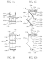
- Fig. 1A is a top view of a first embodiment of the invention
- Fig. 1B is a front view of a first embodiment of the invention;
- Fig. 1C is a sectional view of a first embodiment of the invention;
- Fig. 1D is a side view of a first embodiment of the invention;
- Fig. 1E is a side view of a first embodiment of the invention mounted to a flat parnel;
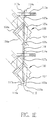
- Fig. 2A is a front view of a second embodiment of the invention
- Fig. 2B is a side view of a second embodiment of the invention
- Fig. 2C is a top view of a second embodiment of the invention
- Fig. 2D is a side view of a second embodiment of the invention mounted to a flat panel;
- Fig. 3A is a side view of a third embodiment of the invention;
- Fig. 3B is a front view of a third embodiment of the invention;
- Fig. 3C is a sectional view of a third embodiment of the invention;
- Fig. 3D is a side view of a third embodiment of the invention mounted to a flat panel.
-
- Throughout the following detailed description similar reference numbers refer to similar elements in all the Figs. of the drawings. Referring to Figs. 1A-1D, several views of a first embodiment of the invention are shown.
Frame 100 is comprised ofhousing 101a,pivot 103a,stop 107a, andlatch 110a.Frame 100 may comprise a single plastic injection-molded assembly, or an assembly of a number of components some or all of which may be plastic or other suitable material. Latch 110a should be formed of a material that is flexible but does not tends towards plastic deformation easily. -
Housing 101a is open atfront 104a and rear 105a to formcentral passageway 102a. Thecentral axis 121 ofcentral passageway 102a should form an oblique angle with the plane of the horizon. Forty-five degrees is optimal, but the oblique angle may be anywhere in the range of 15 to 75 degrees.Central passageway 102a receives and supports two cables joined by connectors or a connector-adaptor assembly when mounted to aflat panel 118 as shown if Fig. 1E. It will be appreciated however thatframe 100 is not limited in the number of connector or connector adapter assemblies that it may support.Frame 100 may be constructed to accommodate a single connector assembly up to several connector assemblies. That portion offrame 100 in contact withcentral passageway 102a comprises housinginner portion 119a. The remaining portions offrame 100 comprise housingouter portion 106a. -
Pivot 103a is attached to housingouter portion 106a forward of housing rear 105a. In general,pivot 103a should rotate about an axis parallel to the plane of the horizon but perpendicular to the central passagewaycentral axis 121 In this embodiment of the invention, the axis of rotation for the pivot also lies in a plane parallel to but aft of a plane extending from firstflat face 120a ofstop 107a.Pivot 103a is comprised offirst ridge 116a andsecond ridge 115a. Bothfirst ridge 116a andsecond ridge 115a extend away from housingouter portion 106a and defineslot 117a. In general,slot 117a may be comprised of one or more inner walls. In this embodiment of theinvention slot 117a is comprised of firstinner wall 121a corresponding tofirst ridge 116a, secondinner wall 122a corresponding tosecond ridge 115a, andupper wall 123a which connects firstinner wall 121a and secondinner wall 122a. Slot first and secondinner walls upper wall 123a different distances. In this embodiment slot firstinner wall 121a extends away from slotupper wall 123a a distance less than the distance slot secondinner wall 122a extends away from slotupper wall 123a. The advantage of having slot firstinner wall 121a extend a distance less than slot secondinner wall 122a is ease of mountingframe 100 topanel 118. -
Stop 107a is attached to housingouter portion 106aopposite pivot 103a and aft ofhousing front 104a. Stop 107a also has aflat face 120a oriented perpendicular to the horizon and open tohousing front 104a. In this embodiment of the invention,stop 107a has afirst section 107a extending from housingouter portion 106a perpendicular to the axis ofcentral passageway 102a for a first distance, asecond section 114a extending fromfirst section 107a for a second distance, firstflat face 120a is defined bysecond section 114a, and the first distance is greater than the second distance. In any event, it is preferable to have the axis of rotation ofpivot 103a lying in a plane parallel to but aft of a plane extending from firstflat face 120a. This ensures thatframe 100 is horizontally aligned once inserted inpanel 118. -
Latch 110a is comprised ofbase section 111a andspring bars 112a.Base section 111a is attached to housingouter portion 106aopposite pivot 103a and forward ofstop 107a.Spring bars 112a are mounted to either end ofbase section 111a and extend in cantilever fashion aroundstop 107a towards housing rear 105a. On each ofspring bars 112a is acatch 113a extending away fromstop 107a mounted aft ofbase section 111a but forward firstflat face 120a.Catch 113a engages the rear face ofpanel 118 whenframe 100 is mounted topanel 118. Whilecatch 113a may take any number of forms, in this embodiment of theinvention catch 113a comprises a ridge having first and second sides, the first side faces towards but slopes away fromhousing front 104a, and the second side faces towards housing rear 105a and forms a plane perpendicular to the central passagewaycentral axis 121 - To mount
frame 100 topanel 118, auser facing panel 118places frame 100 at angle towards himself with slot117a ofpivot 103a straddling the lower edge of an opening inpanel 118. The user then squeezesspring arms 112a towards each other and rotatesframe 100 onpivot 103a until firstflat face 120a ofstop 107a engages the front surface ofpanel 118.Spring arms 112a are released andcatches 113a engage the rear surface ofpanel 118. It will be appreciated that the design offrame 100 provides at least five points of retention: firstflat face 120a and the upper outer surface ofpanel 118;catch 113a second side faces and the upper inner surfaces ofpanel 118; pivot 103a firstinner wall 121a and lower inner surface ofpanel 118; and pivot 103a secondinner wall 122a and lower outer surface ofpanel 118. Prior art connector frames typically provide only two retention points. - Referring now to Figs. 2A-2D, several views of a second embodiment of the invention are shown..
Frame 200 is comprised ofhousing 101b,pivot 103b, and stop 107b.Frame 200 may comprise a single plastic injection-molded assembly, or an assembly of a number of components some or all of which may be plastic or other suitable material. The spring arm portion ofpivot 103b should be formed of a material that is flexible but does not tends towards plastic deformation easily. -
Housing 101b is open at front 104b and rear 105b to form a central passageway (not shown). Thecentral axis 121 of the central passageway should form an oblique angle with the plane of the horizon. Forty-five degrees is optimal, but the oblique angle may be anywhere in the range of 15 to 75 degrees. The central passageway receives and supports four cables joined by two connector or connector adapter assemblies when mounted to aflat panel 118 as shown if Fig. 2D. It will be appreciated however thatframe 200 is not limited in the number of connector or connector adapter assemblies that it may support.Frame 200 can be constructed to accommodate a single connector assembly up to several connector assemblies. That portion offrame 200 in contact with central passageway 102b comprises the housing inner portion (not shown). The remaining portions offrame 200 comprise housingouter portion 106b. -
Pivot 103b is attached to housingouter portion 106b forward of housing rear 105b. In general,pivot 103b should rotate about an axis parallel to the plane of the horizon but perpendicular to central passagewaycentral axis 121b. In this embodiment of the invention, the axis of rotation also lies in a plane parallel to but aft of a plane extending from firstflat face 120b ofstop 107b, andpivot 103b comprises a spring arm extending in cantilever fashion towardshousing front 104b in a plane parallel to the horizon. The spring arm ofpivot 103b comprises a first ridge 116b and a second ridge 115b and defines aslot 117b therein that runs perpendicular to the spring arm on a side thereofopposite housing 101b. In general,slot 117b may comprise one or more inner walls. In this embodiment of the invention,slot 117b comprises firstinner wall 121b, secondinner wall 122b, andupper wall 123b which connects firstinner wall 121b and secondinner wall 122b. -
Stop 107b is attached to housingouter portion 106b oppositepivot 103b and aft ofhousing front 104b. Stop 107b also has aflat face 120b oriented perpendicular to the horizon and open tohousing front 104b. It is preferable to have the axis of rotation ofpivot 117b lying in a plane parallel to but aft of a plane extending from firstflat face 120b. This ensures thatframe 200 is horizontally aligned once inserted inpanel 118. - To mount
frame 200 topanel 118, auser facing panel 118places frame 200 at angle towards himself with slot117b ofpivot 103b straddling the lower edge of an opening inpanel 118. The user then depresseshousing 101b towardspanel 118 and away from himself, thereby causinghousing 101b to rotate about the axis of rotation ofpivot 103b, untilhousing front 104b is behind the rear surface ofpanel 118. Oncehousing front 104b is behind the rear surface ofpanel 118 the user ceases to depresshousing 101b and allows the action ofpivot 103b spring arm to raisehousing 101b vertically until firstflat face 120b ofstop 107b engages the upper outer face ofpanel 118 and a section of housingouter portion 106b forward ofstop 107b engages the upper inner face ofpanel 118. It will be appreciated that the design offrame 200 provides at least four points of retention: firstflat face 120a and the upper outer surface ofpanel 118; housingouter portion 106b forward ofstop 107b and upper inner face ofpanel 118; slot 117b firstinner wall 121b and lower inner surface ofpanel 118; and slot 117b secondinner wall 122b and lower outer surface ofpanel 118. - Referring now to Figs. 3A-3D, several views of a third embodiment of the invention are shown..
Frame 300 is comprised offirst housing 301 andsecond housing 308.First housing 301 is comprised ofbase 302,side walls 303, andfront 304.First housing front 304 andbase 302 are open tofirst cavity 317 formed by firsthousing side walls 303. Arectangular ridge 306 provides a pivot and protrudes from one of the firsthousing side walls 303 alongaxis 315 which forms an oblique angle with the one of the firsthousing side walls 303. Forty-five degrees is optimal, but the oblique angle may be anywhere in the range of 15 to 75 degrees. A face ofrectangular ridge 306 and the one of the firsthousing side walls 303 define mounting notch/orslot 307. It will be appreciated thatridge 306 need not be rectangular in shape but may take a variety of different forms. -
Second housing 308 is comprised ofbase 309,side walls 310, andfront 311.Second housing front 311 andbase 309 are open tosecond cavity 318 formed by secondhousing side walls 310. Atriangular ridge 313 provides a stop with aflat face 321 and protrudes from one of the secondhousing side walls 310 oppositerectangular ridge 306 along an extension ofaxis 315. It will be appreciated thatridge 313 need not be triangular in shape but may take a variety of different forms.Triangular ridge 313 definesrecession 314 therein for receiving a fastener such as a screw or the like.First housing 301 andsecond housing 308 are joined atbases first cavity 317 andsecond cavity 318 form a central passageway having acentral axis 316 and enclose and support a push-pull typefiber optic connector 319. In this embodiment of the invention, at least one of the first and secondhousing side walls key slots Key slot 305 and/or 320 are optional however and need not be present in every embodiment of the invention. - First and
second housings - To mount
frame 300 topanel 118, a user inserts the frame through the panel and then applies downward force to the frame therebymating groove 307 topanel 118. The user then securesframe 300 topanel 118 with a fastener that threads into or attaches torecession 314. - While the invention has been described in connection with the embodiments depicted in the various figures, it is to be understood that other embodiments may be used or modifications and additions may be made to the described embodiments for performing the same function of the invention without deviating therefrom. Therefore, the invention should not be limited to any single embodiment, but rather construed in breadth and scope in accordance with the claims appended below.
Claims (25)
- A frame (100, 200, 300) for mounting a connector at an angle to a flat panel (118),
characterized in that the frame comprises:a housing (101a, 101b, 301, 308) open at a front (104a, 104b, 311) and a rear (105a, 105b, 304) to form a central passageway (102a, 102b, 317, 318) along an oblique axis (121, 316) with respect to the horizon;a pivot (103a, 103b, 306) forward of the housing rear having an axis of rotation parallel to the horizon but perpendicular to the oblique axis (121, 316) of the central passageway;a stop (107a, 107b, 313) opposite the pivot and aft of the housing front, the stop having a first flat face (120a, 120b, 321) oriented perpendicular to the horizon. - The frame according to claim 1 characterized in that it further comprises a latch (110a) formed by a base section (111a) opposite the pivot (103a) forward of the stop (107a) and two roughly parallel spring bars (112a) extending in cantilever fashion around the stop and towards the housing rear from either end of the base section, the spring bars each having a catch (113a) extending away from the stop mounted aft of the base section but forward the face of the stop.
- The frame according to claim 1 characterized in that the stop has a first section (107a) extending from the housing (101a) perpendicular to the oblique axis (121) of the central passageway (102a) for a first distance and a second section (114a) extending from the first section for a second distance, the second section comprising the first flat face (102a).
- The frame according to claim 3 characterized in that the first distance is greater than the second distance.
- The frame according to claim 1 characterized in that the axis of rotation of the pivot lies in a plane parallel to but aft of a plane extending from the first flat face of the stop.
- The frame according to claim 1 characterized in that the pivot comprises ridges (115a, 116a, 115b, 116b, 306) extending away from the housing and defining a slot (117a, 117b, 307) centered about the axis of rotation of the pivot.
- The frame according to claim 6 characterized in that the slot comprises first and second inner walls and an upper wall, the slot first inner wall extends a first distance away from the slot upper wall and the slot second inner wall extends a second distance away from the slot upper wall, the first distance being different from the second distance.
- The frame according to claim 7 characterized in that the first distance is less than the second distance.
- The frame according to claim 2 characterized in that each catch (113a) comprises a ridge having first and second sides, the first side facing towards but sloping away from the housing front.
- The frame according to claim 9 characterized in that the catch second side faces towards the housing rear and is perpendicular to the oblique axis of the housing central passageway.
- The frame according to claim 1 characterized in that the pivot (103b) comprises a spring arm extending in cantilever fashion towards the housing front in a plane parallel to the horizon, the spring arm defining a slot (117b) therein running perpendicular to the spring arm on a side opposite the housing.
- The frame according to claim 11 characterized in that the centerline of the slot (117b) lies in a plane parallel to but aft of a plane extending from the first flat face (120b) of the stop (107b).
- The frame according to claim 1 characterized in that the oblique angle formed with the central axis (121) and the plane of the horizon is in the range of 15 to 75 degrees.
- A frame (300) according to claim 1 for mounting a connector (319) at an angle to a flat panel (118) characterized in that the frame comprisesa first housing (301), the first housing comprising a base (302), side walls (303), and a front (304), the first housing front and base being open to a first cavity (317) formed by the first housing side walls, a first ridge (306) protruding from one of the first housing side walls along a first axis (315) at an oblique angle to the one of the first housing walls and having at least one face, the at least on face of the ridge (306) and the one of the first housing walls (303) defining a mounting slot (307); anda second housing (308), the second housing comprising a base (309), side walls (310), and a front (311), the second housing base joined to the first housing base, the second housing front and base being open to a second cavity (318) formed by the second housing side walls, a second ridge (313) protruding from one of the second housing side walls along an extension of the first axis (315) and having at least one face (321), the at least one face of the second ridge defining a recession (314) therein for receiving a fastener.
- The frame according to claim 14 characterized in that at least one of the side walls of the first and the second housings define a key slot (305, 320) therein.
- The frame according to claim 14 characterized in that the second housing recession is defined along a second axis perpendicular to the extension of the first axis (315).
- The frame according to claim 14 characterized in that the first ridge (306) comprises a rectangular ridge and the second ridge (313) comprises a triangular ridge.
- The frame according to claim 14 characterized in that the oblique angle formed with the central axis (316) and the plane of the horizon is in the range of 15 to 75 degrees.
- A method of mounting a connector at an angle to the face of a flat panel with an opening characterized by the following steps :providing a frame open at a front and a rear to form a central passageway along an oblique axis with respect to the horizon, the frame further comprising a pivot and a stop;placing the connector within the central passageway of the frame;positioning the connector within the opening, the pivot resting on an edge of the mounting opening; androtating the frame towards the panel on the pivot until the stop engages the panel.
- The method according to claim 19 characterized in that the frame further comprises a latch formed by a base section opposite the pivot forward of the stop and two roughly parallel spring bars extending in cantilever fashion around the stop and towards the housing rear from either end of the base section, the spring bars each having a catch extending away from the stop mounted aft of the base section but forward the face of the stop, each of the catches engaging the flat panel on the side opposite the stop once the stop engages the panel.
- The method according to claims 19 and 20 characterized in that it comprises further the step of removing the frame from the panel by squeezing the spring bars and rotating the frame away from the panel on the pivot.
- The method according to claims 19 and 20 characterized in that the stop has a first section extending from the housing perpendicular to the oblique axis of the central passageway for a first distance and second section extending from the first section for a second distance, the second section comprising the first flat face.
- The method according to claim 22 characterized in that the first distance is greater than the second distance.
- The method according to claims 19 and 20 characterized in that the axis of rotation of the pivot lies in a plane parallel to but aft of a plane extending from the first flat face of the stop.
- The method according to claims 19 and 20 characterized in that the pivot comprises a first ridge forward of a second ridge, the ridges extending away from the frame and defining a slot centered about the axis of rotation of the pivot.
Applications Claiming Priority (2)
| Application Number | Priority Date | Filing Date | Title |
|---|---|---|---|
| US09/885,821 US6623170B2 (en) | 2001-06-20 | 2001-06-20 | Angular mounted optical connector adaptor frame |
| US885821 | 2001-06-20 |
Publications (2)
| Publication Number | Publication Date |
|---|---|
| EP1271712A2 true EP1271712A2 (en) | 2003-01-02 |
| EP1271712A3 EP1271712A3 (en) | 2005-11-23 |
Family
ID=25387769
Family Applications (1)
| Application Number | Title | Priority Date | Filing Date |
|---|---|---|---|
| EP02013595A Withdrawn EP1271712A3 (en) | 2001-06-20 | 2002-06-20 | Angular mounted optical connector adaptor frame |
Country Status (4)
| Country | Link |
|---|---|
| US (2) | US6623170B2 (en) |
| EP (1) | EP1271712A3 (en) |
| JP (1) | JP2003066278A (en) |
| CA (1) | CA2390801C (en) |
Cited By (2)
| Publication number | Priority date | Publication date | Assignee | Title |
|---|---|---|---|---|
| EP1580850A1 (en) * | 2004-03-25 | 2005-09-28 | Delphi Technologies, Inc. | Electrical connector |
| WO2007051486A1 (en) | 2005-11-07 | 2007-05-10 | Fci | Electrical connector for mounting in a panel cutout |
Families Citing this family (34)
| Publication number | Priority date | Publication date | Assignee | Title |
|---|---|---|---|---|
| US6760531B1 (en) | 1999-03-01 | 2004-07-06 | Adc Telecommunications, Inc. | Optical fiber distribution frame with outside plant enclosure |
| US6637949B2 (en) * | 2001-06-01 | 2003-10-28 | Adc Telecommunications, Inc. | Method and apparatus for multi-directional fiber optic connection |
| US7029182B2 (en) * | 2002-03-01 | 2006-04-18 | Fci Americas Technology, Inc. | Angled optical connector adapter mounting assembly |
| AUPS120702A0 (en) | 2002-03-18 | 2002-04-18 | Kingfisher International Pty. Ltd. | An optical fibre connector system |
| US6768860B2 (en) * | 2002-12-05 | 2004-07-27 | Jds Uniphase Inc. | High density fiber optic module |
| US7142764B2 (en) | 2003-03-20 | 2006-11-28 | Tyco Electronics Corporation | Optical fiber interconnect cabinets, termination modules and fiber connectivity management for the same |
| US7198409B2 (en) | 2003-06-30 | 2007-04-03 | Adc Telecommunications, Inc. | Fiber optic connector holder and method |
| US7233731B2 (en) | 2003-07-02 | 2007-06-19 | Adc Telecommunications, Inc. | Telecommunications connection cabinet |
| US6983095B2 (en) | 2003-11-17 | 2006-01-03 | Fiber Optic Network Solutions Corporation | Systems and methods for managing optical fibers and components within an enclosure in an optical communications network |
| US7369741B2 (en) | 2003-11-17 | 2008-05-06 | Fiber Optics Network Solutions Corp. | Storage adapter with dust cap posts |
| US7218827B2 (en) | 2004-06-18 | 2007-05-15 | Adc Telecommunications, Inc. | Multi-position fiber optic connector holder and method |
| DE102004031110B4 (en) * | 2004-06-28 | 2008-02-14 | Wöhner GmbH & Co. KG Elektrotechnische Systeme | safety switch |
| US7194181B2 (en) | 2005-03-31 | 2007-03-20 | Adc Telecommunications, Inc. | Adapter block including connector storage |
| US7760984B2 (en) | 2006-05-04 | 2010-07-20 | Adc Telecommunications, Inc. | Fiber distribution hub with swing frame and wrap-around doors |
| US20080050967A1 (en) * | 2006-08-24 | 2008-02-28 | Chris Poulin | Connector adapters for use in usb applications |
| US8229265B2 (en) | 2007-11-21 | 2012-07-24 | Adc Telecommunications, Inc. | Fiber distribution hub with multiple configurations |
| CN103543501B (en) | 2008-08-27 | 2016-08-24 | Adc电信公司 | There is the fiber adapter of the ferrule alignment structure of global formation |
| MX2011005380A (en) | 2008-11-21 | 2011-06-06 | Adc Telecommunications Inc | Fiber optic telecommunications module. |
| WO2011107180A1 (en) | 2010-03-02 | 2011-09-09 | Adc Gmbh | Fibre-optic telecommunication module |
| US8600208B2 (en) | 2010-08-24 | 2013-12-03 | Adc Telecommunications, Inc. | Fiber optic telecommunications module |
| US9417418B2 (en) | 2011-09-12 | 2016-08-16 | Commscope Technologies Llc | Flexible lensed optical interconnect device for signal distribution |
| AU2012321127B2 (en) | 2011-10-07 | 2016-02-04 | Commscope Technologies Llc | Fiber optic cassette |
| US20140072263A1 (en) * | 2012-09-10 | 2014-03-13 | Alliance Fiber Optic Products, Inc. | Optical fiber adapter having vertical wings |
| US9146362B2 (en) | 2012-09-21 | 2015-09-29 | Adc Telecommunications, Inc. | Insertion and removal tool for a fiber optic ferrule alignment sleeve |
| WO2014052441A1 (en) | 2012-09-28 | 2014-04-03 | Tyco Electronic Uk Ltd. | Fiber optic cassette |
| US9146374B2 (en) | 2012-09-28 | 2015-09-29 | Adc Telecommunications, Inc. | Rapid deployment packaging for optical fiber |
| US9223094B2 (en) | 2012-10-05 | 2015-12-29 | Tyco Electronics Nederland Bv | Flexible optical circuit, cassettes, and methods |
| US9435975B2 (en) | 2013-03-15 | 2016-09-06 | Commscope Technologies Llc | Modular high density telecommunications frame and chassis system |
| JP2014202921A (en) * | 2013-04-04 | 2014-10-27 | 日本通信電材株式会社 | Adapter receiving member |
| WO2015116672A1 (en) | 2014-01-28 | 2015-08-06 | Adc Telecommunications, Inc. | Slidable fiber optic connection module with cable slack management |
| US9494758B2 (en) | 2014-04-03 | 2016-11-15 | Commscope Technologies Llc | Fiber optic distribution system |
| WO2016184363A1 (en) | 2015-05-15 | 2016-11-24 | 爱德奇电讯国际贸易(上海)有限公司 | Alignment sleeve assembly and optical fibre adapter |
| MX2020002878A (en) | 2017-10-02 | 2020-07-22 | Commscope Technologies Llc | Fiber optic circuit and preparation method. |
| FR3097695B1 (en) * | 2019-06-24 | 2021-07-09 | Schneider Electric Ind Sas | Fixing wedge and electrical cabinet comprising such a wedge |
Citations (3)
| Publication number | Priority date | Publication date | Assignee | Title |
|---|---|---|---|---|
| GB1590478A (en) * | 1977-10-13 | 1981-06-03 | Ward Goldstone Ltd | Housing for an electrical connector |
| US5735714A (en) * | 1995-04-06 | 1998-04-07 | Ortronics Inc. | Information management outlet module and assembly providing protection to exposed cabling |
| US5779500A (en) * | 1995-04-24 | 1998-07-14 | Sumitomo Wiring Systems, Ltd. | Snap-fit connector |
Family Cites Families (27)
| Publication number | Priority date | Publication date | Assignee | Title |
|---|---|---|---|---|
| US34955A (en) * | 1862-04-15 | Improvement in seeding-machines | ||
| US2460636A (en) | 1948-09-09 | 1949-02-01 | Charles M Holloway | Self-sealing electric light socket for refrigerator panels |
| US3387253A (en) | 1965-09-27 | 1968-06-04 | Motorola Inc | Convenience plug |
| US4119359A (en) | 1977-08-25 | 1978-10-10 | Stanford Applied Engineering, Inc. | Phono-socket assembly and method |
| US4678260A (en) * | 1984-05-14 | 1987-07-07 | Allied Corporation | EMI shielded electrical connector |
| US4669802A (en) | 1986-03-26 | 1987-06-02 | Amp Incorporated | Outlet for optical fiber connectors |
| US4995688A (en) | 1989-07-31 | 1991-02-26 | Adc Telecommunications, Inc. | Optical fiber distribution frame |
| US5100221A (en) * | 1990-01-22 | 1992-03-31 | Porta Systems Corp. | Optical fiber cable distribution frame and support |
| US5082344A (en) | 1990-03-09 | 1992-01-21 | Mulholland Denis G | Adapter assembly with improved receptacle for a push-pull coupling type of optical fiber connector |
| US5127082A (en) | 1991-03-22 | 1992-06-30 | The Siemon Company | Fiber optic patch panel |
| JP2566190Y2 (en) * | 1992-05-29 | 1998-03-25 | 住友電装株式会社 | Body fixing connector |
| CA2081608C (en) * | 1992-10-28 | 1998-05-05 | Joseph Octave Regis Morin | Distribution frame and optical connector holder combination |
| US5363465A (en) | 1993-02-19 | 1994-11-08 | Adc Telecommunications, Inc. | Fiber optic connector module |
| US5432875A (en) | 1993-02-19 | 1995-07-11 | Adc Telecommunications, Inc. | Fiber optic monitor module |
| JP2567945Y2 (en) * | 1993-03-11 | 1998-04-08 | 住友電装株式会社 | Protection cap for panel mounting connector |
| US5302140A (en) | 1993-04-02 | 1994-04-12 | At&T Bell Laboratories | Connector with mounting collar for use in universal patch panel systems |
| US5363467A (en) | 1993-05-28 | 1994-11-08 | Minnesota Mining And Manufacturing Company | Compact fiber optic housing |
| JP2784369B2 (en) * | 1993-08-30 | 1998-08-06 | 矢崎総業株式会社 | Panel lock connector |
| US5530954A (en) | 1995-01-13 | 1996-06-25 | Telect, Inc. | Telecommunication fiber optic patch panel shelf assembly |
| JP3517472B2 (en) | 1995-03-02 | 2004-04-12 | 富士写真フイルム株式会社 | Print head device |
| US5757997A (en) | 1995-12-22 | 1998-05-26 | Minnesota Mining And Manufacturing Company | Optical fiber connector using fiber spring force alignment groove |
| US5897395A (en) | 1997-05-30 | 1999-04-27 | Lucent Technologies Inc. | Multi-position jack frame |
| JPH10335007A (en) * | 1997-06-02 | 1998-12-18 | Sumitomo Wiring Syst Ltd | Connector |
| DE69833956T2 (en) | 1998-01-15 | 2007-10-18 | The Siemon Co., Watertown | TELECOMMUNICATION PLUG WITH IMPROVED PERFORMANCE |
| TW433604U (en) * | 1999-11-02 | 2001-05-01 | Hon Hai Prec Ind Co Ltd | Connector having a locking device |
| TW478670U (en) * | 1999-11-02 | 2002-03-01 | Hon Hai Prec Ind Co Ltd | Fastening device |
| US6508593B1 (en) * | 2000-05-09 | 2003-01-21 | Molex Incorporated | Universal panel mount system for fiber optic connecting devices |
-
2001
- 2001-06-20 US US09/885,821 patent/US6623170B2/en not_active Expired - Lifetime
-
2002
- 2002-06-17 CA CA2390801A patent/CA2390801C/en not_active Expired - Fee Related
- 2002-06-19 JP JP2002178488A patent/JP2003066278A/en not_active Withdrawn
- 2002-06-20 EP EP02013595A patent/EP1271712A3/en not_active Withdrawn
-
2003
- 2003-07-18 US US10/622,263 patent/US6796717B2/en not_active Expired - Lifetime
Patent Citations (3)
| Publication number | Priority date | Publication date | Assignee | Title |
|---|---|---|---|---|
| GB1590478A (en) * | 1977-10-13 | 1981-06-03 | Ward Goldstone Ltd | Housing for an electrical connector |
| US5735714A (en) * | 1995-04-06 | 1998-04-07 | Ortronics Inc. | Information management outlet module and assembly providing protection to exposed cabling |
| US5779500A (en) * | 1995-04-24 | 1998-07-14 | Sumitomo Wiring Systems, Ltd. | Snap-fit connector |
Cited By (2)
| Publication number | Priority date | Publication date | Assignee | Title |
|---|---|---|---|---|
| EP1580850A1 (en) * | 2004-03-25 | 2005-09-28 | Delphi Technologies, Inc. | Electrical connector |
| WO2007051486A1 (en) | 2005-11-07 | 2007-05-10 | Fci | Electrical connector for mounting in a panel cutout |
Also Published As
| Publication number | Publication date |
|---|---|
| CA2390801A1 (en) | 2002-12-20 |
| JP2003066278A (en) | 2003-03-05 |
| EP1271712A3 (en) | 2005-11-23 |
| US20020197017A1 (en) | 2002-12-26 |
| CA2390801C (en) | 2012-03-20 |
| US6623170B2 (en) | 2003-09-23 |
| US20040017980A1 (en) | 2004-01-29 |
| US6796717B2 (en) | 2004-09-28 |
Similar Documents
| Publication | Publication Date | Title |
|---|---|---|
| EP1271712A2 (en) | Angular mounted optical connector adaptor frame | |
| EP0842554B1 (en) | Modular jack subassembly for use in a network outlet | |
| US5302140A (en) | Connector with mounting collar for use in universal patch panel systems | |
| JP4511054B2 (en) | Jack access card | |
| US7387517B2 (en) | Connector mounting structure | |
| US6287128B1 (en) | Interconnection bracket used in an optical transceiver module | |
| US5562493A (en) | Network interface assembly and mounting frame | |
| US5645449A (en) | Low profile mixed media information outlet | |
| US8231410B2 (en) | Electrical connector with surfaces with exposed grooves permitting contacts to be assembled in a direction perpendicular to a mating direction | |
| US20050233647A1 (en) | Non-orthogonal cable management system | |
| TW200838068A (en) | Rotatable connector modules with inverted jacks | |
| US20040023559A1 (en) | Electrical adapter | |
| KR101076985B1 (en) | Patch panel for mounting on a wall or in a subrack | |
| EP0887893A2 (en) | Multi-position jack frame | |
| US6210217B1 (en) | Electrical connector system having a connector mounted on a conductive panel | |
| US5688129A (en) | Electrical connector with lead positioning comb | |
| US5839922A (en) | 110 wiring block interlock and interlocked blocks utilizing such | |
| JP4073483B2 (en) | Wire stuffer cap / strain relief for communication network outlets | |
| US4447106A (en) | Panel mounted modular jack | |
| US6071150A (en) | Extender for use with computer internal structure | |
| EP0622868A2 (en) | Data communications outlet kit | |
| CN100369531C (en) | Connector holding structure | |
| CA2738576A1 (en) | Angular mounted optical connector adaptor frame | |
| EP0708495B1 (en) | Electrical connector | |
| US11395436B2 (en) | Modular telecommunications patch panel system |
Legal Events
| Date | Code | Title | Description |
|---|---|---|---|
| PUAI | Public reference made under article 153(3) epc to a published international application that has entered the european phase |
Free format text: ORIGINAL CODE: 0009012 |
|
| AK | Designated contracting states |
Kind code of ref document: A2 Designated state(s): AT BE CH CY DE DK ES FI FR GB GR IE IT LI LU MC NL PT SE TR |
|
| AX | Request for extension of the european patent |
Free format text: AL;LT;LV;MK;RO;SI |
|
| PUAL | Search report despatched |
Free format text: ORIGINAL CODE: 0009013 |
|
| AK | Designated contracting states |
Kind code of ref document: A3 Designated state(s): AT BE CH CY DE DK ES FI FR GB GR IE IT LI LU MC NL PT SE TR |
|
| AX | Request for extension of the european patent |
Extension state: AL LT LV MK RO SI |
|
| 17P | Request for examination filed |
Effective date: 20060523 |
|
| AKX | Designation fees paid |
Designated state(s): AT BE CH CY DE DK ES FI FR GB GR IE IT LI LU MC NL PT SE TR |
|
| RAP1 | Party data changed (applicant data changed or rights of an application transferred) |
Owner name: FCI |
|
| 17Q | First examination report despatched |
Effective date: 20120917 |
|
| STAA | Information on the status of an ep patent application or granted ep patent |
Free format text: STATUS: THE APPLICATION IS DEEMED TO BE WITHDRAWN |
|
| 18D | Application deemed to be withdrawn |
Effective date: 20130129 |