EP1270331A1 - Arrangement in connection with a lighting fixture, and a lighting fixture - Google Patents
Arrangement in connection with a lighting fixture, and a lighting fixture Download PDFInfo
- Publication number
- EP1270331A1 EP1270331A1 EP02396101A EP02396101A EP1270331A1 EP 1270331 A1 EP1270331 A1 EP 1270331A1 EP 02396101 A EP02396101 A EP 02396101A EP 02396101 A EP02396101 A EP 02396101A EP 1270331 A1 EP1270331 A1 EP 1270331A1
- Authority
- EP
- European Patent Office
- Prior art keywords
- lighting
- lighting fixture
- light source
- light
- guide
- Prior art date
- Legal status (The legal status is an assumption and is not a legal conclusion. Google has not performed a legal analysis and makes no representation as to the accuracy of the status listed.)
- Withdrawn
Links
Images

Classifications
-
- B—PERFORMING OPERATIONS; TRANSPORTING
- B60—VEHICLES IN GENERAL
- B60Q—ARRANGEMENT OF SIGNALLING OR LIGHTING DEVICES, THE MOUNTING OR SUPPORTING THEREOF OR CIRCUITS THEREFOR, FOR VEHICLES IN GENERAL
- B60Q3/00—Arrangement of lighting devices for vehicle interiors; Lighting devices specially adapted for vehicle interiors
- B60Q3/40—Arrangement of lighting devices for vehicle interiors; Lighting devices specially adapted for vehicle interiors specially adapted for specific vehicle types
- B60Q3/41—Arrangement of lighting devices for vehicle interiors; Lighting devices specially adapted for vehicle interiors specially adapted for specific vehicle types for mass transit vehicles, e.g. buses
- B60Q3/43—General lighting
-
- B—PERFORMING OPERATIONS; TRANSPORTING
- B60—VEHICLES IN GENERAL
- B60Q—ARRANGEMENT OF SIGNALLING OR LIGHTING DEVICES, THE MOUNTING OR SUPPORTING THEREOF OR CIRCUITS THEREFOR, FOR VEHICLES IN GENERAL
- B60Q3/00—Arrangement of lighting devices for vehicle interiors; Lighting devices specially adapted for vehicle interiors
- B60Q3/60—Arrangement of lighting devices for vehicle interiors; Lighting devices specially adapted for vehicle interiors characterised by optical aspects
- B60Q3/62—Arrangement of lighting devices for vehicle interiors; Lighting devices specially adapted for vehicle interiors characterised by optical aspects using light guides
- B60Q3/64—Arrangement of lighting devices for vehicle interiors; Lighting devices specially adapted for vehicle interiors characterised by optical aspects using light guides for a single lighting device
-
- F—MECHANICAL ENGINEERING; LIGHTING; HEATING; WEAPONS; BLASTING
- F21—LIGHTING
- F21Y—INDEXING SCHEME ASSOCIATED WITH SUBCLASSES F21K, F21L, F21S and F21V, RELATING TO THE FORM OR THE KIND OF THE LIGHT SOURCES OR OF THE COLOUR OF THE LIGHT EMITTED
- F21Y2113/00—Combination of light sources
Definitions
- the present invention relates to an arrangement in connection with a lighting fixture, the arrangement comprising a first light source arranged in connection with the lighting fixture structure.
- the lighting in the passenger cabin is adjusted for instance in such a way that when the external lighting decreases, the level of lighting in the passenger cabin is lowered, so that the contrast between the lighting conditions outside the vehicle and inside it would not disturb passengers. Dimmed lighting also creates better conditions for sleeping in the passenger cabin. During dimmed lighting, it is typically possible for the passengers to use personal reading lamps, if desired.
- a dimming function becomes possible for instance by using fluorescent lamps, the actuator of which is an electronic ballast.
- Using such a ballast allows the lighting provided with a fluorescent lamp to be dimmed steplessly up to a certain level.
- the minimum lighting provided with fluorescent lamps is in the order of 2 to 5% of the ordinary lighting level of the lamp, this minimum level being often too strong to be comfortable, in particular during dark times.
- the overall efficiency of fluorescent lighting is significantly reduced because of dimming, whereby, however, the energy consumption for example at a lighting level of 5% is as much as 30% of the ordinary level due to the additional equipment and heater circuits required for the burning of a fluorescent lamp.
- Another option to decrease lighting in passenger cabins is to use only a part of the passenger cabin lamps. Partial use of lamps causes, however, uneven distribution of light, there being apparent differences in lighting in different parts of the passenger cabin. Further, partial use of lamps consumes the lamps used for lighting unevenly and causes thus additional maintanence costs.
- Publication US 5,647,658 discloses a fiber-optic lighting system for aircrafts.
- fiber-optic cables are used alone for lighting an aircraft cabin.
- Light is supplied to the fibers by using a high-intensity lamp, and the lighting provided by the fibres is used as the general lighting of the aircraft.
- An object of the present invention is to provide an arrangement avoiding the above-mentioned drawbacks and allowing implementation of dimmed lighting more simply and reliably than previously.
- the object is achieved with an arrangement according to the invention, characterized in that the arrangement further comprises one or more second light sources and an optic guide, which comprises a first end, a second end and a guide portion between them, is arranged to transmit light over the guide portion between the first end and the second end, and is arranged in connection with a lighting fixture to provide dimmer lighting compared with the lighting provided with the first light source, whereby one or more second light sources is/are arranged in connection with one end or both ends of the optic guide and to function as the light source of the optic guide.
- the invention is based on the idea that lighting dimmer than the ordinary lighting can be implemented by connecting to the lighting fixture an optic guide the side of which transmits light.
- an optic guide can be positioned outside the lighting fixture structure, or alternatively, inside the lighting fixture structure, whereby reflection surfaces or other structures can be used to direct and modify the lighting provided by the guide.
- An object of the invention is also a lighting fixture arranged to receive one or more first light sources and comprising a reflection part and a globe part, the lighting fixture being characterized in that it also comprises one or more elongated grooves arranged to receive an optic guide to provide lighting that is dimmer than the lighting provided with the first light source.
- a lighting fixture structure allows implementation of a lighting arrangement according to the invention in a simple manner.
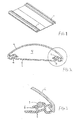
- Figure 1 shows a structure part of a lighting fixture of an embodiment according to the invention
- Figure 2 shows a cross-section of an embodiment of the arrangement according to the invention
- Figure 3 shows a detailed illustration of the cross-section of Figure 2
- Figure 4 shows a partial cross-section of a second embodiment of the arrangement according to the invention.
- Figure 5 shows a cross-section of the embodiment of Figure 4.
- Figure 1 shows a lighting fixture structure applicable to be used in the arrangement according to the invention.
- Figure 1 shows only the structure forming the reflection portion, i.e. the background portion of the lighting fixture.
- the reflection part is typically fitted to the ceiling or the like structure of the space to be illuminated, in which case the lighting primarily takes place from up downwards.
- This background part is usually formed in such a way that it reflects the light directed at it by the light source of the lighting fixture in the direction of lighting.
- the arrangement according to the invention comprises a first light source and one or more second light sources.
- the first light source is a fluorescent lamp.
- the first light source is used as a primary light source, the general lighting being provided with it in the positioning place of the lighting fixture.
- a typical object of positioning the arrangement according to the invention is a passenger cabin in a public transport vehicle.
- a public transport vehicle refers for instance to a bus, a train, a mini-bus or the like transport vehicle intended to carry several passengers.
- the arrangement of the invention further comprises an optic guide 1 arranged to transmit light supplied to the inside of it from one end, at least over a part of its length.
- An optic guide is for example of the type disclosed in international publication WO 9808024.
- the optic guide can be made to transmit light from its side by guiding light to the inside of the guide from one end thereof, or alternatively, from both ends.
- the optic guide of the arrangement according to the invention comprises a first end and a second end and a guide portion between these ends. The guide portion functions thus as a light source when light is guided to it in the way described above.
- the optic guide is arranged in connection with a lighting fixture to provide lighting dimmer than the lighting provided with the first light source.
- Figure 2 shows the cross-section of the structure of an embodiment according to the invention.
- the cross-section indicates the background part of the lighting fixture, i.e. a reflection part 3, and a globe part 2 connected to each other.
- the globe part is used to protect fluorescent lamps and to modify the lighting provided by them.
- the globe is naturally made of a light-transmitting material, which, for instance, softens the light provided by the light source.
- the background part 3 is typically fitted to the ceiling or the like structure of the space to be illuminated, the lighting taking place primarily from up downwards.
- the invention of the general lighting is to provide even lighting, whereby the background part is to provide the object to be illuminated with lighting that is as even as possible.
- Figure 2 does not show the first light source.
- the first light source is a fluorescent lamp. According to the luminosity required, several fluorescent lamps can be used in one lighting fixture. It is obvious, however, that in Figure 2 the first light sources are positioned inside a space 4 formed by the reflection part and the globe part.
- Figure 2 shows an optic guide 1 according to the arrangement of the invention, there being two such guides positioned inside the space formed by the reflection part and the globe part in accordance with the invention.
- the optic guides are attached to grooves in the background part 3, one of the grooves being shown in greater detail in Figure 3.
- the arrangement according to the invention also comprises one or more second light sources. These second light sources are used for supplying light to the optic guides.
- the second light source is a light-emitting diode.
- a fluorescent, incandescent or other corresponding lamp can be used as the second light source.
- An advantage of light-emitting diodes is the low luminosity required and the very long lifetime.
- light-emitting diodes are available in a plurality of different colours, whereby the crepuscular lighting of a passenger cabin can be implemented as coloured lighting in a simple manner. Coloured or shaded lighting can also be implemented by using conventional fluorescent or incandescent lamps. In such a case, separate filters must be used to achieve the desired shade.
- the idea of the invention is that when light sources used for ordinary lighting, i.e. the first light sources, can no longer be dimmed, the optic guides 1 are taken into use and the use of the first light sources is stopped completely, or light of a different colour, such as green, red, blue or yellow, is provided with the second light source. Although the luminosity provided with an optic guide is low, it is still pleasant and sufficient in dim or dark conditions.
- the lighting fixtures are elongate when the object of use of the lighting fixture is the passenger cabin of a public transport vehicle.
- the lighting fixtures are to be positioned evenly over a distance of several meters to achieve even lighting in the whole passenger cabin.
- the lighting can be implemented with a light line.
- a light line forms one long lighting fixture structure, which can be implemented with several fluorescent lamps positioned one after another.
- lighting can be implemented conventionally by using separate lighting fixtures.
- the lighting fixtures can be of any form; thus, they can be round or oval, for example.
- the optic guide 1 of the arrangement according to the invention comprises a first and a second end and a guide portion between them.
- the optic guide is, in accordance with the embodiment, illuminated from its both ends. In this way, the size of the guide portion capable of illumination can be increased significantly.
- the optic guide can be connected according to the invention to be in connection with both a light line and a separate lighting fixture. Due to the restricted size of the guide portion capable of illumination, as many optic guides as required must be positioned in connection with the light line.
- Figures 1, 2 and 3 show an embodiment in which the optic guide is positioned inside the globe 2 of the lighting fixture.
- the invention can, however, be applied in such a way that the optic guide is positioned outside the lighting fixture structure.
- Such an embodiment is shown in Figures 4 and 5.
- the optic guide 1 is in the embodiment mounted on the outer surface of the lighting fixture structure, in an elongate groove 6.
- the groove is formed at the outer edge of the background part 3, whereby the optic guide stays outside the space 4 formed by the reflection part 3 and the globe part 2.
- the arrangement can be implemented by using a lighting fixture according to the invention, some embodiments of which are shown in Figures 1 to 5.
- elongate grooves 6 receiving the optic guide are arranged in both the inside and the outside of the lighting fixture.
- suitable objects of positioning include the outer edges of the lighting fixture, ceiling structures, luggage rack structures and other fixed structures in the passenger cabin, from which the light provided by the optic guide illuminates the passenger cabin in a desired manner.
- the simplest way to use the arrangement is such that the driver of a transport vehicle, for instance, has lighting control devices by means of which the lighting can be dimmed.
- the first light sources have been dimmed to the maximum value
- the second light sources begin to produce light that illuminates the passenger cabin via optic guides.
- the control devices may also have different switches for the use of the two light sources. It is also feasible to dim the lighting of the passenger cabin automatically by means of optic sensors.
Abstract
Description
- The present invention relates to an arrangement in connection with a lighting fixture, the arrangement comprising a first light source arranged in connection with the lighting fixture structure.
- In several objects of use of lighting fixtures, adaptability is required of the lighting according to the particular lighting needs and possibly changing conditions. This is the case for instance in public transport vehicles, such as buses, trains and trams, where the level of lighting is adjusted in accordance with generally changing conditions and to make passengers feel more comfortable.
- Also inside buildings it is often recommendable to be able to dim the lighting without darkening the particular space completely. Such is the case for example in various serviced flats and the like, where there must always be some kind of lighting in the corridors.
- In public transport vehicles, the lighting in the passenger cabin is adjusted for instance in such a way that when the external lighting decreases, the level of lighting in the passenger cabin is lowered, so that the contrast between the lighting conditions outside the vehicle and inside it would not disturb passengers. Dimmed lighting also creates better conditions for sleeping in the passenger cabin. During dimmed lighting, it is typically possible for the passengers to use personal reading lamps, if desired.
- Decreasing the lighting is also applied when a vehicle is transported without passengers. In such a case, it is unnecessary to maintain full lighting in the passenger cabin, but for the sake of the driver's safety and the passengers' comfort, there is a reason to maintain some lighting in the passenger cabin.
- Presently, decreasing the lighting is implemented in vehicle passenger cabins by using lamps that can be dimmed. A dimming function becomes possible for instance by using fluorescent lamps, the actuator of which is an electronic ballast. Using such a ballast allows the lighting provided with a fluorescent lamp to be dimmed steplessly up to a certain level. However, the minimum lighting provided with fluorescent lamps is in the order of 2 to 5% of the ordinary lighting level of the lamp, this minimum level being often too strong to be comfortable, in particular during dark times. Further, the overall efficiency of fluorescent lighting is significantly reduced because of dimming, whereby, however, the energy consumption for example at a lighting level of 5% is as much as 30% of the ordinary level due to the additional equipment and heater circuits required for the burning of a fluorescent lamp.
- Another option to decrease lighting in passenger cabins is to use only a part of the passenger cabin lamps. Partial use of lamps causes, however, uneven distribution of light, there being apparent differences in lighting in different parts of the passenger cabin. Further, partial use of lamps consumes the lamps used for lighting unevenly and causes thus additional maintanence costs.
- Publication US 5,647,658 discloses a fiber-optic lighting system for aircrafts. In the system of the publication, fiber-optic cables are used alone for lighting an aircraft cabin. Light is supplied to the fibers by using a high-intensity lamp, and the lighting provided by the fibres is used as the general lighting of the aircraft.
- An object of the present invention is to provide an arrangement avoiding the above-mentioned drawbacks and allowing implementation of dimmed lighting more simply and reliably than previously. The object is achieved with an arrangement according to the invention, characterized in that the arrangement further comprises one or more second light sources and an optic guide, which comprises a first end, a second end and a guide portion between them, is arranged to transmit light over the guide portion between the first end and the second end, and is arranged in connection with a lighting fixture to provide dimmer lighting compared with the lighting provided with the first light source, whereby one or more second light sources is/are arranged in connection with one end or both ends of the optic guide and to function as the light source of the optic guide.
- The invention is based on the idea that lighting dimmer than the ordinary lighting can be implemented by connecting to the lighting fixture an optic guide the side of which transmits light. Such an optic guide can be positioned outside the lighting fixture structure, or alternatively, inside the lighting fixture structure, whereby reflection surfaces or other structures can be used to direct and modify the lighting provided by the guide.
- With the solution according to the invention, for instance passenger cabins of public transport vehicles can be provided with dimmer and more even lighting compared with existing solutions, because optic guides can be freely positioned over the whole area of the passenger cabins. In addition, colour shades of the lighting can be changed in a simple manner, because the light is produced for the optic guide from one or both ends by using light-emitting diodes, i.e. LEDs, that are availabe in several different colours. In this way, dim lighting can be provided in a passenger cabin, which lighting is not only both dimmer and more even than in the previous solutions but has also an atmospheric colour shade and is generally pleasant for passengers' eyes. Further, using LEDs reduces maintenance costs significantly, because the lifetime of LEDs is very long compared with conventional incandescent or fluorescent lamps.
- An object of the invention is also a lighting fixture arranged to receive one or more first light sources and comprising a reflection part and a globe part, the lighting fixture being characterized in that it also comprises one or more elongated grooves arranged to receive an optic guide to provide lighting that is dimmer than the lighting provided with the first light source. Such a lighting fixture structure allows implementation of a lighting arrangement according to the invention in a simple manner.
- The invention will now be described in more detail in connection with preferred embodiments of which
- Figure 1 shows a structure part of a lighting fixture of an embodiment according to the invention;
- Figure 2 shows a cross-section of an embodiment of the arrangement according to the invention;
- Figure 3 shows a detailed illustration of the cross-section of Figure 2;
- Figure 4 shows a partial cross-section of a second embodiment of the arrangement according to the invention; and
- Figure 5 shows a cross-section of the embodiment of Figure 4.
- Figure 1 shows a lighting fixture structure applicable to be used in the arrangement according to the invention. Figure 1 shows only the structure forming the reflection portion, i.e. the background portion of the lighting fixture. The reflection part is typically fitted to the ceiling or the like structure of the space to be illuminated, in which case the lighting primarily takes place from up downwards. This background part is usually formed in such a way that it reflects the light directed at it by the light source of the lighting fixture in the direction of lighting.
- The arrangement according to the invention comprises a first light source and one or more second light sources. In accordance with a preferred embodiment of the invention, the first light source is a fluorescent lamp. The first light source is used as a primary light source, the general lighting being provided with it in the positioning place of the lighting fixture. A typical object of positioning the arrangement according to the invention is a passenger cabin in a public transport vehicle. A public transport vehicle refers for instance to a bus, a train, a mini-bus or the like transport vehicle intended to carry several passengers.
- The arrangement of the invention further comprises an
optic guide 1 arranged to transmit light supplied to the inside of it from one end, at least over a part of its length. An optic guide is for example of the type disclosed in international publication WO 9808024. The optic guide can be made to transmit light from its side by guiding light to the inside of the guide from one end thereof, or alternatively, from both ends. Thus, the optic guide of the arrangement according to the invention comprises a first end and a second end and a guide portion between these ends. The guide portion functions thus as a light source when light is guided to it in the way described above. - In accordance with the invention, the optic guide is arranged in connection with a lighting fixture to provide lighting dimmer than the lighting provided with the first light source. Figure 2 shows the cross-section of the structure of an embodiment according to the invention. The cross-section indicates the background part of the lighting fixture, i.e. a reflection part 3, and a globe part 2 connected to each other. The globe part is used to protect fluorescent lamps and to modify the lighting provided by them. The globe is naturally made of a light-transmitting material, which, for instance, softens the light provided by the light source.
- As mentioned earlier, the background part 3 is typically fitted to the ceiling or the like structure of the space to be illuminated, the lighting taking place primarily from up downwards. In addition, the invention of the general lighting is to provide even lighting, whereby the background part is to provide the object to be illuminated with lighting that is as even as possible.
- Figure 2 does not show the first light source. In accordance with the embodiment, the first light source is a fluorescent lamp. According to the luminosity required, several fluorescent lamps can be used in one lighting fixture. It is obvious, however, that in Figure 2 the first light sources are positioned inside a
space 4 formed by the reflection part and the globe part. - Figure 2 shows an
optic guide 1 according to the arrangement of the invention, there being two such guides positioned inside the space formed by the reflection part and the globe part in accordance with the invention. In the embodiment, the optic guides are attached to grooves in the background part 3, one of the grooves being shown in greater detail in Figure 3. The arrangement according to the invention also comprises one or more second light sources. These second light sources are used for supplying light to the optic guides. Preferably, the second light source is a light-emitting diode. Also, a fluorescent, incandescent or other corresponding lamp can be used as the second light source. An advantage of light-emitting diodes is the low luminosity required and the very long lifetime. Further, light-emitting diodes are available in a plurality of different colours, whereby the crepuscular lighting of a passenger cabin can be implemented as coloured lighting in a simple manner. Coloured or shaded lighting can also be implemented by using conventional fluorescent or incandescent lamps. In such a case, separate filters must be used to achieve the desired shade. - The idea of the invention is that when light sources used for ordinary lighting, i.e. the first light sources, can no longer be dimmed, the optic guides 1 are taken into use and the use of the first light sources is stopped completely, or light of a different colour, such as green, red, blue or yellow, is provided with the second light source. Although the luminosity provided with an optic guide is low, it is still pleasant and sufficient in dim or dark conditions.
- As becomes obvious from the figure, the lighting fixtures are elongate when the object of use of the lighting fixture is the passenger cabin of a public transport vehicle. Thus it is obvious that the lighting fixtures are to be positioned evenly over a distance of several meters to achieve even lighting in the whole passenger cabin. Thus, the lighting can be implemented with a light line. In practice, a light line forms one long lighting fixture structure, which can be implemented with several fluorescent lamps positioned one after another. In public transport vehicles, lighting can be implemented conventionally by using separate lighting fixtures. The lighting fixtures can be of any form; thus, they can be round or oval, for example.
- As mentioned earlier, the
optic guide 1 of the arrangement according to the invention comprises a first and a second end and a guide portion between them. In order to make the guide portion capable of illumination longer, the optic guide is, in accordance with the embodiment, illuminated from its both ends. In this way, the size of the guide portion capable of illumination can be increased significantly. The optic guide can be connected according to the invention to be in connection with both a light line and a separate lighting fixture. Due to the restricted size of the guide portion capable of illumination, as many optic guides as required must be positioned in connection with the light line. - Figures 1, 2 and 3 show an embodiment in which the optic guide is positioned inside the globe 2 of the lighting fixture. The invention can, however, be applied in such a way that the optic guide is positioned outside the lighting fixture structure. Such an embodiment is shown in Figures 4 and 5. As becomes obvious from the figures, the
optic guide 1 is in the embodiment mounted on the outer surface of the lighting fixture structure, in anelongate groove 6. In the embodiment, the groove is formed at the outer edge of the background part 3, whereby the optic guide stays outside thespace 4 formed by the reflection part 3 and the globe part 2. At its simplest, the arrangement can be implemented by using a lighting fixture according to the invention, some embodiments of which are shown in Figures 1 to 5. In the embodiment of the lighting fixture shown in Figures 4 and 5,elongate grooves 6 receiving the optic guide are arranged in both the inside and the outside of the lighting fixture. Thus, using the same structure, it is possible to select between two positioning options for the optical guides providing dim lighting. - It is not necessary, however, to position the guide fixedly in the lighting fixture structure. In passenger cabins of public transport vehicles, suitable objects of positioning include the outer edges of the lighting fixture, ceiling structures, luggage rack structures and other fixed structures in the passenger cabin, from which the light provided by the optic guide illuminates the passenger cabin in a desired manner.
- The simplest way to use the arrangement is such that the driver of a transport vehicle, for instance, has lighting control devices by means of which the lighting can be dimmed. When the first light sources have been dimmed to the maximum value, the second light sources begin to produce light that illuminates the passenger cabin via optic guides. The control devices may also have different switches for the use of the two light sources. It is also feasible to dim the lighting of the passenger cabin automatically by means of optic sensors.
- In the above, the invention has been described particularly in connection with a public transport vehicle. It is understandable, however, that the arrangement according to the invention can be applied to several different objects of use without restricting it only to public transport vehicles.
- It will be obvious to a person skilled in the art that with the advance of technology, the basic idea of the invention can be implemented in a plurality of ways. Thus, the invention and its embodiments are not confined to the above examples but can vary within the scope of the claims.
Claims (9)
- An arrangement in connection with a lighting fixture, the arrangement comprising a first light source arranged in connection with the lighting fixture structure (2, 3), characterized in that it further comprises one or more second light sources and an optic guide (1), which
comprises a first end, a second end and a guide portion between them;
is arranged to transmit light over the guide portion between the first end and the second end; and
is arranged in connection with a lighting fixture to provide dimmer lighting compared with the lighting provided with the first light source, whereby one or more second light sources is/are arranged in connection with one end or both ends of the optic guide (1) and to function as the light source of the optic guide (1). - An arrangement according to claim 1, characterized in that the first light source is a fluorescent lamp.
- An arrangement according to claim 1, characterized in that the first light source is an incandescent lamp.
- An arrangement according to claim 1, 2 or 3, characterized in that the second light source is a light-emitting diode.
- An arrangement according to any one of claims 1 to 4, where the lighting fixture comprises an enclosed structure (2, 3), inside which the first light source is arranged, characterized in that the optic guide (1) is at least partly arranged inside the enclosed structure of the lighting fixture.
- An arrangement according to any one of claims 1 to 4, where the lighting fixture comprises an enclosed structure (2, 3), inside which the first light source is arranged, characterized in that the optic guide (1) is arranged outside the enclosed structure of the lighting fixture.
- A lighting fixture arranged to receive one or more first light sources and comprising a reflection part (3) and a globe part (2), the lighting fixture being characterized in that
it also comprises one or more elongated grooves (6) arranged to receive an optic guide (1) to provide lighting that is dimmer than the lighting provided with the first light source. - A lighting fixture according to claim 7, where the reflection part (3) and the globe part (2) combined form a substantially solid structure, characterized in that the elongate groove (6) of the lighting fixture is arranged in the reflection part (3) inside the solid structure.
- A lighting fixture according to claim 7, where the reflection part (3) and the globe part (2) combined form a substantially solid structure, characterized in that the elongate groove (6) of the lighting fixture is arranged in the reflection part (3) outside the solid structure.
Applications Claiming Priority (2)
| Application Number | Priority Date | Filing Date | Title |
|---|---|---|---|
| FI20011407A FI110636B (en) | 2001-06-29 | 2001-06-29 | Arrangements in connection with a lighting fixture and a lighting fixture |
| FI20011407 | 2001-06-29 |
Publications (1)
| Publication Number | Publication Date |
|---|---|
| EP1270331A1 true EP1270331A1 (en) | 2003-01-02 |
Family
ID=8561539
Family Applications (1)
| Application Number | Title | Priority Date | Filing Date |
|---|---|---|---|
| EP02396101A Withdrawn EP1270331A1 (en) | 2001-06-29 | 2002-06-25 | Arrangement in connection with a lighting fixture, and a lighting fixture |
Country Status (3)
| Country | Link |
|---|---|
| US (1) | US7090375B2 (en) |
| EP (1) | EP1270331A1 (en) |
| FI (1) | FI110636B (en) |
Cited By (5)
| Publication number | Priority date | Publication date | Assignee | Title |
|---|---|---|---|---|
| GB2412721A (en) * | 2004-03-31 | 2005-10-05 | Honda Access Kk | Interior illuminator for an automobile |
| DE102006042648A1 (en) * | 2006-09-12 | 2008-03-27 | Diehl Aerospace Gmbh | Lighting module for lighting cabin of aircraft, has multiple light emitting diodes, with reflector and with screen, where light emitting diodes are arranged in area covered by observation zone of screen |
| US7850337B2 (en) * | 2003-12-30 | 2010-12-14 | Lg Display Co., Ltd. | LCD device and method of driving the LCD device |
| WO2012160139A1 (en) | 2011-05-24 | 2012-11-29 | Johnson Controls Interiors Gmbh & Co. Kg | Lighting device for a vehicle interior |
| CN103101478A (en) * | 2011-10-13 | 2013-05-15 | 丰田纺织株式会社 | Light source unit assembly |
Families Citing this family (20)
| Publication number | Priority date | Publication date | Assignee | Title |
|---|---|---|---|---|
| DE102006037376A1 (en) * | 2006-08-09 | 2008-02-14 | Patent-Treuhand-Gesellschaft für elektrische Glühlampen mbH | lamp |
| DE102007030186B4 (en) * | 2007-06-27 | 2009-04-23 | Harald Hofmann | Linear LED lamp and lighting system with the same |
| JP5261684B2 (en) * | 2007-11-27 | 2013-08-14 | スタンレー電気株式会社 | Strobe device |
| US7887216B2 (en) | 2008-03-10 | 2011-02-15 | Cooper Technologies Company | LED-based lighting system and method |
| US7997757B2 (en) * | 2008-06-13 | 2011-08-16 | Cooper Technologies Company | Luminaire with integral signage endcaps |
| US20090310330A1 (en) * | 2008-06-13 | 2009-12-17 | Cooper Technologies Company | Combination Luminaire and Path of Egress Lighting |
| US8038314B2 (en) * | 2009-01-21 | 2011-10-18 | Cooper Technologies Company | Light emitting diode troffer |
| US8454192B2 (en) * | 2009-06-05 | 2013-06-04 | Abl Ip Holding Llc | Strip lighting fixture with channel |
| US8142047B2 (en) * | 2009-12-14 | 2012-03-27 | Abl Ip Holding Llc | Architectural lighting |
| CN102788265B (en) * | 2011-05-20 | 2014-07-09 | 扬升照明股份有限公司 | Light-emitting diode lamp |
| US8985820B2 (en) * | 2012-08-10 | 2015-03-24 | GM Global Technology Operations LLC | Lighted vehicle interior accessory assembly and method |
| US20140071673A1 (en) | 2012-09-11 | 2014-03-13 | Abl Ip Holding Llc | Recessed Luminaire |
| US20140177219A1 (en) * | 2012-12-20 | 2014-06-26 | Ecolite Manufacturing Co. | Low Profile Light Fixture |
| USD696449S1 (en) | 2013-03-14 | 2013-12-24 | Lsi Industries, Inc. | Lighting |
| US9127826B2 (en) * | 2013-03-14 | 2015-09-08 | Lsi Industries, Inc. | Indirect lighting luminaire |
| US9822937B2 (en) | 2014-06-16 | 2017-11-21 | Abl Ip Holding Llc | Light engine retrofit kit and method for installing same |
| MX370617B (en) | 2015-02-04 | 2019-12-17 | Abl Ip Holding Llc | Easy install light engine retrofit kit and method for using same. |
| CN107922384A (en) * | 2015-07-29 | 2018-04-17 | 埃斯蒂文博士实验室股份有限公司 | There are the amide derivatives of multi-mode activity to pain |
| USD800374S1 (en) * | 2016-03-11 | 2017-10-17 | Sylwester Klus | Housing for LED-based lighting apparatus |
| USD868351S1 (en) * | 2018-08-25 | 2019-11-26 | Led Labs Sp. Z O.O. | Housing for a LED-based lighting apparatus |
Citations (9)
| Publication number | Priority date | Publication date | Assignee | Title |
|---|---|---|---|---|
| US4941074A (en) * | 1988-12-29 | 1990-07-10 | Road Rescue, Inc. | Light boxes |
| DE29620583U1 (en) * | 1996-11-27 | 1997-02-13 | Kundisch Microtech Gmbh & Co K | Lighting fixture with continuously adjustable color change of the light and the light cone |
| US5647658A (en) | 1995-05-11 | 1997-07-15 | Ziadi; Bouchaib | Fiber-optic lighting system |
| WO1998008024A1 (en) | 1996-08-19 | 1998-02-26 | Kostron Oy | Light emitting cable or similar band |
| DE19858810A1 (en) * | 1998-12-21 | 2000-06-29 | Patent Treuhand Ges Fuer Elektrische Gluehlampen Mbh | Flat lighting device and operating method |
| US6106140A (en) * | 1998-02-20 | 2000-08-22 | Diehl Stiftung & Co. | Lighting arrangement for freight compartments |
| EP1078816A2 (en) * | 1999-08-23 | 2001-02-28 | Ichikoh Industries Limited | Vehicle lighting device using led light source |
| JP2001138808A (en) * | 1999-06-28 | 2001-05-22 | Toyoda Gosei Co Ltd | Interior lighting system for vehicle |
| US6238075B1 (en) * | 1996-12-17 | 2001-05-29 | Transmatic, Inc. | Lighting system for mass-transit vehicles |
Family Cites Families (7)
| Publication number | Priority date | Publication date | Assignee | Title |
|---|---|---|---|---|
| US5736686A (en) * | 1995-03-01 | 1998-04-07 | Gtco Corporation | Illumination apparatus for a digitizer tablet with improved light panel |
| US5883684A (en) * | 1997-06-19 | 1999-03-16 | Three-Five Systems, Inc. | Diffusively reflecting shield optically, coupled to backlit lightguide, containing LED's completely surrounded by the shield |
| US6206535B1 (en) * | 1999-11-30 | 2001-03-27 | Hayashi Telempu Co., Ltd. | Planar lighting device and method of making light guides used therein |
| DE19963336A1 (en) * | 1999-12-27 | 2001-07-12 | Hella Kg Hueck & Co | Lighting device and method for illuminating a coupling-out space for vehicles |
| DE20007134U1 (en) | 2000-04-18 | 2000-08-17 | Patent Treuhand Ges Fuer Elektrische Gluehlampen Mbh | Luminaire with adjustable color location |
| JP2002075037A (en) * | 2000-09-05 | 2002-03-15 | Minebea Co Ltd | Surface lighting equipment |
| FI117303B (en) * | 2002-02-12 | 2006-08-31 | Teknoware Oy | ILLUMINATOR |
-
2001
- 2001-06-29 FI FI20011407A patent/FI110636B/en not_active IP Right Cessation
-
2002
- 2002-06-25 US US10/179,084 patent/US7090375B2/en not_active Expired - Fee Related
- 2002-06-25 EP EP02396101A patent/EP1270331A1/en not_active Withdrawn
Patent Citations (10)
| Publication number | Priority date | Publication date | Assignee | Title |
|---|---|---|---|---|
| US4941074A (en) * | 1988-12-29 | 1990-07-10 | Road Rescue, Inc. | Light boxes |
| US5647658A (en) | 1995-05-11 | 1997-07-15 | Ziadi; Bouchaib | Fiber-optic lighting system |
| WO1998008024A1 (en) | 1996-08-19 | 1998-02-26 | Kostron Oy | Light emitting cable or similar band |
| DE29620583U1 (en) * | 1996-11-27 | 1997-02-13 | Kundisch Microtech Gmbh & Co K | Lighting fixture with continuously adjustable color change of the light and the light cone |
| US6238075B1 (en) * | 1996-12-17 | 2001-05-29 | Transmatic, Inc. | Lighting system for mass-transit vehicles |
| US6106140A (en) * | 1998-02-20 | 2000-08-22 | Diehl Stiftung & Co. | Lighting arrangement for freight compartments |
| DE19858810A1 (en) * | 1998-12-21 | 2000-06-29 | Patent Treuhand Ges Fuer Elektrische Gluehlampen Mbh | Flat lighting device and operating method |
| JP2001138808A (en) * | 1999-06-28 | 2001-05-22 | Toyoda Gosei Co Ltd | Interior lighting system for vehicle |
| US6402354B1 (en) * | 1999-06-28 | 2002-06-11 | Toyoda Gosei Co., Ltd. | Indirect lighting system for vehicle interior |
| EP1078816A2 (en) * | 1999-08-23 | 2001-02-28 | Ichikoh Industries Limited | Vehicle lighting device using led light source |
Cited By (9)
| Publication number | Priority date | Publication date | Assignee | Title |
|---|---|---|---|---|
| US7850337B2 (en) * | 2003-12-30 | 2010-12-14 | Lg Display Co., Ltd. | LCD device and method of driving the LCD device |
| GB2412721A (en) * | 2004-03-31 | 2005-10-05 | Honda Access Kk | Interior illuminator for an automobile |
| US7213952B2 (en) | 2004-03-31 | 2007-05-08 | Honda Access Corporation | Interior illuminator for automobile |
| GB2412721B (en) * | 2004-03-31 | 2007-09-12 | Honda Access Kk | Interior illuminator for automobile |
| DE102005013837B4 (en) * | 2004-03-31 | 2008-01-10 | Honda Access Corp. | Interior light for an automobile |
| DE102006042648A1 (en) * | 2006-09-12 | 2008-03-27 | Diehl Aerospace Gmbh | Lighting module for lighting cabin of aircraft, has multiple light emitting diodes, with reflector and with screen, where light emitting diodes are arranged in area covered by observation zone of screen |
| WO2012160139A1 (en) | 2011-05-24 | 2012-11-29 | Johnson Controls Interiors Gmbh & Co. Kg | Lighting device for a vehicle interior |
| CN103101478A (en) * | 2011-10-13 | 2013-05-15 | 丰田纺织株式会社 | Light source unit assembly |
| CN103101478B (en) * | 2011-10-13 | 2015-05-06 | 丰田纺织株式会社 | Light source unit assembly |
Also Published As
| Publication number | Publication date |
|---|---|
| FI110636B (en) | 2003-02-28 |
| FI20011407A (en) | 2002-12-30 |
| US20030002289A1 (en) | 2003-01-02 |
| US7090375B2 (en) | 2006-08-15 |
Similar Documents
| Publication | Publication Date | Title |
|---|---|---|
| US7090375B2 (en) | Arrangement in connection with a lighting fixture, and a lighting fixture | |
| US6929382B2 (en) | Lighting fixture | |
| US5647658A (en) | Fiber-optic lighting system | |
| EP2118559B1 (en) | Camouflaged composite military vehicle lamp | |
| US20130141925A1 (en) | Low glare lighting for a transit vehicle | |
| NZ520431A (en) | Lamp | |
| US10107460B2 (en) | Method and system for retrofitting luminaires | |
| EP3116782B1 (en) | Lighting systems | |
| US9695990B2 (en) | Arrangement for light emission | |
| JP2003212038A (en) | Luminaire | |
| DE102008017271B4 (en) | Luminaire with two light sources in a recess of an at least partially photoconductive support, use of this lamp as a pendant, wall or floor lamp and lighting device for such a lamp | |
| US8348451B2 (en) | Invisible emergency illumination for an aircraft cabin | |
| EP3179162B1 (en) | Methods and apparatus for cabin lighting for aircraft main cabin | |
| GB2553337A (en) | Dome light assembly for a vehicle, cabin for a vehicle comprising a dome light assembly, and vehicle comprising a cabin with a dome light assembly | |
| CN207758788U (en) | A kind of compartment and train | |
| US6752521B2 (en) | Lighting arrangement for public transport vehicles | |
| US6428175B1 (en) | Advisory lighting fitting | |
| CN211738753U (en) | Lighting device and passenger car | |
| CN211780794U (en) | Interior dome lamp and have passenger train of this interior dome lamp | |
| CN215204877U (en) | Rail vehicle lighting system and rail vehicle | |
| CN211119022U (en) | Color lamp | |
| KR0124617Y1 (en) | A mood lamp for a bus | |
| ITTO990909A1 (en) | MOTOR VEHICLE EQUIPPED WITH A DASHBOARD LIGHTING GROUP. | |
| Novakovsky et al. | RECONSTRUCTION OF ILLUMINATION DEVICES AT THE MOSCOW METRO | |
| GB2525167A (en) | Lighting systems |
Legal Events
| Date | Code | Title | Description |
|---|---|---|---|
| PUAI | Public reference made under article 153(3) epc to a published international application that has entered the european phase |
Free format text: ORIGINAL CODE: 0009012 |
|
| AK | Designated contracting states |
Kind code of ref document: A1 Designated state(s): AT BE CH CY DE DK ES FI FR GB GR IE IT LI LU MC NL PT SE TR |
|
| AX | Request for extension of the european patent |
Free format text: AL;LT;LV;MK;RO;SI |
|
| 17P | Request for examination filed |
Effective date: 20030206 |
|
| AKX | Designation fees paid |
Designated state(s): AT BE CH CY DE DK ES FI FR GB GR IE IT LI LU MC NL PT SE TR |
|
| 17Q | First examination report despatched |
Effective date: 20091109 |
|
| STAA | Information on the status of an ep patent application or granted ep patent |
Free format text: STATUS: THE APPLICATION IS DEEMED TO BE WITHDRAWN |
|
| 18D | Application deemed to be withdrawn |
Effective date: 20121107 |