EP1270073A1 - Microfluidic system with controller - Google Patents
Microfluidic system with controller Download PDFInfo
- Publication number
- EP1270073A1 EP1270073A1 EP01115587A EP01115587A EP1270073A1 EP 1270073 A1 EP1270073 A1 EP 1270073A1 EP 01115587 A EP01115587 A EP 01115587A EP 01115587 A EP01115587 A EP 01115587A EP 1270073 A1 EP1270073 A1 EP 1270073A1
- Authority
- EP
- European Patent Office
- Prior art keywords
- electrode
- channel
- channels
- fluid
- electrical
- Prior art date
- Legal status (The legal status is an assumption and is not a legal conclusion. Google has not performed a legal analysis and makes no representation as to the accuracy of the status listed.)
- Granted
Links
Images

Classifications
-
- B—PERFORMING OPERATIONS; TRANSPORTING
- B01—PHYSICAL OR CHEMICAL PROCESSES OR APPARATUS IN GENERAL
- B01L—CHEMICAL OR PHYSICAL LABORATORY APPARATUS FOR GENERAL USE
- B01L3/00—Containers or dishes for laboratory use, e.g. laboratory glassware; Droppers
- B01L3/50—Containers for the purpose of retaining a material to be analysed, e.g. test tubes
- B01L3/502—Containers for the purpose of retaining a material to be analysed, e.g. test tubes with fluid transport, e.g. in multi-compartment structures
- B01L3/5027—Containers for the purpose of retaining a material to be analysed, e.g. test tubes with fluid transport, e.g. in multi-compartment structures by integrated microfluidic structures, i.e. dimensions of channels and chambers are such that surface tension forces are important, e.g. lab-on-a-chip
- B01L3/50273—Containers for the purpose of retaining a material to be analysed, e.g. test tubes with fluid transport, e.g. in multi-compartment structures by integrated microfluidic structures, i.e. dimensions of channels and chambers are such that surface tension forces are important, e.g. lab-on-a-chip characterised by the means or forces applied to move the fluids
-
- B—PERFORMING OPERATIONS; TRANSPORTING
- B01—PHYSICAL OR CHEMICAL PROCESSES OR APPARATUS IN GENERAL
- B01L—CHEMICAL OR PHYSICAL LABORATORY APPARATUS FOR GENERAL USE
- B01L3/00—Containers or dishes for laboratory use, e.g. laboratory glassware; Droppers
- B01L3/50—Containers for the purpose of retaining a material to be analysed, e.g. test tubes
- B01L3/502—Containers for the purpose of retaining a material to be analysed, e.g. test tubes with fluid transport, e.g. in multi-compartment structures
- B01L3/5027—Containers for the purpose of retaining a material to be analysed, e.g. test tubes with fluid transport, e.g. in multi-compartment structures by integrated microfluidic structures, i.e. dimensions of channels and chambers are such that surface tension forces are important, e.g. lab-on-a-chip
- B01L3/502715—Containers for the purpose of retaining a material to be analysed, e.g. test tubes with fluid transport, e.g. in multi-compartment structures by integrated microfluidic structures, i.e. dimensions of channels and chambers are such that surface tension forces are important, e.g. lab-on-a-chip characterised by interfacing components, e.g. fluidic, electrical, optical or mechanical interfaces
-
- G—PHYSICS
- G01—MEASURING; TESTING
- G01N—INVESTIGATING OR ANALYSING MATERIALS BY DETERMINING THEIR CHEMICAL OR PHYSICAL PROPERTIES
- G01N27/00—Investigating or analysing materials by the use of electric, electrochemical, or magnetic means
- G01N27/26—Investigating or analysing materials by the use of electric, electrochemical, or magnetic means by investigating electrochemical variables; by using electrolysis or electrophoresis
- G01N27/416—Systems
- G01N27/447—Systems using electrophoresis
- G01N27/44704—Details; Accessories
- G01N27/44717—Arrangements for investigating the separated zones, e.g. localising zones
-
- G—PHYSICS
- G01—MEASURING; TESTING
- G01N—INVESTIGATING OR ANALYSING MATERIALS BY DETERMINING THEIR CHEMICAL OR PHYSICAL PROPERTIES
- G01N27/00—Investigating or analysing materials by the use of electric, electrochemical, or magnetic means
- G01N27/26—Investigating or analysing materials by the use of electric, electrochemical, or magnetic means by investigating electrochemical variables; by using electrolysis or electrophoresis
- G01N27/416—Systems
- G01N27/447—Systems using electrophoresis
- G01N27/44704—Details; Accessories
- G01N27/44752—Controlling the zeta potential, e.g. by wall coatings
-
- G—PHYSICS
- G01—MEASURING; TESTING
- G01N—INVESTIGATING OR ANALYSING MATERIALS BY DETERMINING THEIR CHEMICAL OR PHYSICAL PROPERTIES
- G01N27/00—Investigating or analysing materials by the use of electric, electrochemical, or magnetic means
- G01N27/26—Investigating or analysing materials by the use of electric, electrochemical, or magnetic means by investigating electrochemical variables; by using electrolysis or electrophoresis
- G01N27/416—Systems
- G01N27/447—Systems using electrophoresis
- G01N27/44756—Apparatus specially adapted therefor
- G01N27/44791—Microapparatus
-
- B—PERFORMING OPERATIONS; TRANSPORTING
- B01—PHYSICAL OR CHEMICAL PROCESSES OR APPARATUS IN GENERAL
- B01L—CHEMICAL OR PHYSICAL LABORATORY APPARATUS FOR GENERAL USE
- B01L2200/00—Solutions for specific problems relating to chemical or physical laboratory apparatus
- B01L2200/14—Process control and prevention of errors
- B01L2200/143—Quality control, feedback systems
-
- B—PERFORMING OPERATIONS; TRANSPORTING
- B01—PHYSICAL OR CHEMICAL PROCESSES OR APPARATUS IN GENERAL
- B01L—CHEMICAL OR PHYSICAL LABORATORY APPARATUS FOR GENERAL USE
- B01L2300/00—Additional constructional details
- B01L2300/06—Auxiliary integrated devices, integrated components
- B01L2300/0627—Sensor or part of a sensor is integrated
- B01L2300/0645—Electrodes
-
- B—PERFORMING OPERATIONS; TRANSPORTING
- B01—PHYSICAL OR CHEMICAL PROCESSES OR APPARATUS IN GENERAL
- B01L—CHEMICAL OR PHYSICAL LABORATORY APPARATUS FOR GENERAL USE
- B01L2300/00—Additional constructional details
- B01L2300/08—Geometry, shape and general structure
- B01L2300/0809—Geometry, shape and general structure rectangular shaped
- B01L2300/0816—Cards, e.g. flat sample carriers usually with flow in two horizontal directions
-
- B—PERFORMING OPERATIONS; TRANSPORTING
- B01—PHYSICAL OR CHEMICAL PROCESSES OR APPARATUS IN GENERAL
- B01L—CHEMICAL OR PHYSICAL LABORATORY APPARATUS FOR GENERAL USE
- B01L2300/00—Additional constructional details
- B01L2300/08—Geometry, shape and general structure
- B01L2300/0861—Configuration of multiple channels and/or chambers in a single devices
- B01L2300/0867—Multiple inlets and one sample wells, e.g. mixing, dilution
-
- B—PERFORMING OPERATIONS; TRANSPORTING
- B01—PHYSICAL OR CHEMICAL PROCESSES OR APPARATUS IN GENERAL
- B01L—CHEMICAL OR PHYSICAL LABORATORY APPARATUS FOR GENERAL USE
- B01L2400/00—Moving or stopping fluids
- B01L2400/04—Moving fluids with specific forces or mechanical means
- B01L2400/0403—Moving fluids with specific forces or mechanical means specific forces
- B01L2400/0415—Moving fluids with specific forces or mechanical means specific forces electrical forces, e.g. electrokinetic
-
- B—PERFORMING OPERATIONS; TRANSPORTING
- B01—PHYSICAL OR CHEMICAL PROCESSES OR APPARATUS IN GENERAL
- B01L—CHEMICAL OR PHYSICAL LABORATORY APPARATUS FOR GENERAL USE
- B01L2400/00—Moving or stopping fluids
- B01L2400/04—Moving fluids with specific forces or mechanical means
- B01L2400/0403—Moving fluids with specific forces or mechanical means specific forces
- B01L2400/043—Moving fluids with specific forces or mechanical means specific forces magnetic forces
-
- B—PERFORMING OPERATIONS; TRANSPORTING
- B01—PHYSICAL OR CHEMICAL PROCESSES OR APPARATUS IN GENERAL
- B01L—CHEMICAL OR PHYSICAL LABORATORY APPARATUS FOR GENERAL USE
- B01L2400/00—Moving or stopping fluids
- B01L2400/04—Moving fluids with specific forces or mechanical means
- B01L2400/0403—Moving fluids with specific forces or mechanical means specific forces
- B01L2400/0433—Moving fluids with specific forces or mechanical means specific forces vibrational forces
- B01L2400/0436—Moving fluids with specific forces or mechanical means specific forces vibrational forces acoustic forces, e.g. surface acoustic waves [SAW]
-
- B—PERFORMING OPERATIONS; TRANSPORTING
- B01—PHYSICAL OR CHEMICAL PROCESSES OR APPARATUS IN GENERAL
- B01L—CHEMICAL OR PHYSICAL LABORATORY APPARATUS FOR GENERAL USE
- B01L2400/00—Moving or stopping fluids
- B01L2400/04—Moving fluids with specific forces or mechanical means
- B01L2400/0475—Moving fluids with specific forces or mechanical means specific mechanical means and fluid pressure
- B01L2400/0487—Moving fluids with specific forces or mechanical means specific mechanical means and fluid pressure fluid pressure, pneumatics
-
- B—PERFORMING OPERATIONS; TRANSPORTING
- B01—PHYSICAL OR CHEMICAL PROCESSES OR APPARATUS IN GENERAL
- B01L—CHEMICAL OR PHYSICAL LABORATORY APPARATUS FOR GENERAL USE
- B01L3/00—Containers or dishes for laboratory use, e.g. laboratory glassware; Droppers
- B01L3/02—Burettes; Pipettes
- B01L3/0241—Drop counters; Drop formers
-
- Y—GENERAL TAGGING OF NEW TECHNOLOGICAL DEVELOPMENTS; GENERAL TAGGING OF CROSS-SECTIONAL TECHNOLOGIES SPANNING OVER SEVERAL SECTIONS OF THE IPC; TECHNICAL SUBJECTS COVERED BY FORMER USPC CROSS-REFERENCE ART COLLECTIONS [XRACs] AND DIGESTS
- Y10—TECHNICAL SUBJECTS COVERED BY FORMER USPC
- Y10T—TECHNICAL SUBJECTS COVERED BY FORMER US CLASSIFICATION
- Y10T137/00—Fluid handling
- Y10T137/0318—Processes
- Y10T137/0396—Involving pressure control
-
- Y—GENERAL TAGGING OF NEW TECHNOLOGICAL DEVELOPMENTS; GENERAL TAGGING OF CROSS-SECTIONAL TECHNOLOGIES SPANNING OVER SEVERAL SECTIONS OF THE IPC; TECHNICAL SUBJECTS COVERED BY FORMER USPC CROSS-REFERENCE ART COLLECTIONS [XRACs] AND DIGESTS
- Y10—TECHNICAL SUBJECTS COVERED BY FORMER USPC
- Y10T—TECHNICAL SUBJECTS COVERED BY FORMER US CLASSIFICATION
- Y10T137/00—Fluid handling
- Y10T137/206—Flow affected by fluid contact, energy field or coanda effect [e.g., pure fluid device or system]
- Y10T137/218—Means to regulate or vary operation of device
- Y10T137/2191—By non-fluid energy field affecting input [e.g., transducer]
- Y10T137/2196—Acoustical or thermal energy
-
- Y—GENERAL TAGGING OF NEW TECHNOLOGICAL DEVELOPMENTS; GENERAL TAGGING OF CROSS-SECTIONAL TECHNOLOGIES SPANNING OVER SEVERAL SECTIONS OF THE IPC; TECHNICAL SUBJECTS COVERED BY FORMER USPC CROSS-REFERENCE ART COLLECTIONS [XRACs] AND DIGESTS
- Y10—TECHNICAL SUBJECTS COVERED BY FORMER USPC
- Y10T—TECHNICAL SUBJECTS COVERED BY FORMER US CLASSIFICATION
- Y10T137/00—Fluid handling
- Y10T137/8158—With indicator, register, recorder, alarm or inspection means
- Y10T137/8326—Fluid pressure responsive indicator, recorder or alarm
Definitions
- the invention relates to a microfluid system, in particular a microfluid chip at least one working channel in which a fluid and / or contained therein Components by means of a driving force, in particular by using Pressure, acoustic energy, an electrical and / or a magnetic field are movable in the direction of the working channel and a method for transport and the guidance of a fluid and / or components contained therein, in one such microfluid system.
- Such a device and such a method are known from US 5,965,001, US 5,800,690 and from Electrophoresis (2000), pages 100-106 and pages 107 to 115 previously known.
- the content of these documents is attached to this Job fully included for any purpose, as in these Documents important features, especially regarding the constructive and material training of such microfluidic systems and possible ones Procedures for the transportation and management of fluids and / or contained therein Components in such microfluidic systems are disclosed, that is, features, for individually or in combination with each other, in combination with those in this Registration additional features disclosed protection is claimed.
- Such microfluidic systems are of particular interest for applications in Field of electroosmosis and / or electrophoresis, for reasons of Economy and a correspondingly larger range of applications preferred open network of fluid-connected miniature channels is used.
- These electrical parameters are usually introduced into the fluid by means of suitable electrodes respective ends of the partially intersecting channels with so-called reservoirs are contacted, which in turn are in fluid communication with the individual microchannels stand.
- Assay defined, i.e. for a given microfluidic system, preferably one Microfluidic chip, certain reagents and a certain data analysis and also a certain time sequence for the electrical parameters, in particular the electrical current and / or the electrical voltage certain temperatures for each electrode in a so-called table "Script" set.
- the user will eventually see a log of that Field of application of the respective microfluid system and its respective application limits informed.
- This protocol also defines the limits regarding the using substances or fluids and their concentrations. This Limits must also be due to the time invariant statically defined in the script Parameters are comparatively narrowly defined.
- the electrical Parameters especially the electrical currents and / or the electrical ones Voltages at the individual electrodes are graded in certain time periods changed, with special electrical circuits, such as current or voltage regulator Make sure that the respective electrical parameters are above the desired Period of time at the respective electrode can be kept constant.
- Microfluid system i.e. the more fluid-connected micro-channels are provided.
- the more fluid-connected micro-channels are provided.
- four channels which at one point form a cross-connection are fluid-connected and at the end each have a reservoir and an electrode are provided an independent increase in fluid flow between two Reservoirs not only by increasing the voltage difference across the achievable in both reservoirs.
- the tensions on the other two reservoirs must also be reset if the original flow and to keep its direction.
- usually different ones different electrical parameters simultaneously on several electrodes i.e. according to the respective script.
- microfluid systems are subject to this both internal and external disturbance variables, which the test result also because of the access to the others, if any Channels, can significantly influence.
- Such disturbances can, for example due to the manufacturing process due to slight dimensional deviations of the microfluid channels be conditional.
- the term "microfluid” refers to miniature channels that one Have cross-section in the order of 0.1 to 500 microns. typical Dimensions of such miniature channels are, for example, 15 ⁇ m deep and 40 ⁇ m width.
- the respective channel geometry essentially determines the effective one Resistance of a liquid, so that the flow and the electrical Characteristics when changing the channel geometry also corresponding change.
- the manufacturing tolerances for the manufacture of such miniature channels are however, there are limits for economic reasons.
- Electrodes are not directly in or on the Micro channels of the microfluid system can be used as it is connected to the Electrodes often leads to an undesirable gas bubble formation.
- gas bubbles can increase the miniaturized channels effective resistance up to an infinitely large effective resistance to lead.
- the electrodes are usually made with reservoirs connected, which can accommodate a comparatively large volume of fluid and the significantly larger dimensions compared to the geometry of the miniature channels exhibit.
- this means that the electrodes are inserted at the respective end of the Miniature channels limited.
- microfluid system and a method for transporting and guiding a fluid and / or components contained therein in such a microfluidic system that has a wider application and Range of use and a reduced sensitivity to internal and / or external disturbance variables and consequently greater operational reliability.
- the working channel opening measuring channel is fluidly connected, which is coupled to the sensor.
- suitable measuring and / or Intervention options for the introduction and / or discharge of electrical Create parameters by making quasi "virtual" electrodes available there become.
- the microfluid system is expediently provided with an open network of channels fluidly connected to one another, at least three, preferably four of the channels in a common, in particular point-like formed channel space open, wherein one of the channels acts as a measuring channel.
- an open network of channels fluidly connected to one another, at least three, preferably four of the channels in a common, in particular point-like formed channel space open, wherein one of the channels acts as a measuring channel.
- the working channel is provided at least two electrodes for exercising an electrical and / or magnetic Field connected to the fluid, with at least one working electrode can be acted upon with electrical current and / or electrical voltage and wherein at least one measuring electrode serves as a sensor.
- This arrangement has changed in particular for a regulation of Fluid processes when using microfluidic systems in the field of electroosmosis or electrophoresis has proven to be advantageous.
- the above task is also accomplished by a method of transportation and the Guidance of a fluid and / or components contained therein in a microfluid system, in particular a microfluid chip, with at least one working channel, in which the fluid and / or components contained therein by means of a driving Force, especially by applying pressure, acoustic energy, one electrical and / or a magnetic field in the direction of the working channel is moved, solved, one with a sensor for measuring a the fluid assigned measurement variable and a device that can be derived in the region of the fluid to change the driving force and / or an influence thereby Characteristic of coupled controllers, the driving force and / or the influence that can be influenced thereby Characteristic regulates.
- the controller expediently regulates the driving force and / or thereby parameter that can be influenced in such a way that it is particularly independent of internal parameters and / or external disturbance variables are kept essentially constant, so that greater operational reliability and a wider range of applications are possible.
- Constant is within the scope of the revelation this property right is not just an absolute characteristic value that remains constant over time meant, but an arbitrary characteristic function over time, for example a "gradient” or a “ramp”, but this is due to the regulation according to the invention is kept invariant in response to internal or external interference.
- the controller has the driving force and / or the thereby influencing parameter regulates such that the gradient of the driving Force and / or the gradient of the parameter that can be influenced by the driving force over a certain section of the working channel, especially regardless of internal and / or external disturbance variables is kept essentially constant or become.
- the controller has the driving force and / or the thereby influencing parameter regulates such that the gradient of the driving Force and / or the gradient of the parameter that can be influenced by the driving force over a certain section of the working channel, especially regardless of internal and / or external disturbance variables is kept essentially constant or become.
- the controller is the driving force and / or the result influenceable parameter regulates such that an essentially constant or predetermined Joule power loss is reached, so that in the fluid filament the temperature of the working channel is kept constant or the Temperature increase can be determined and consequently another arithmetical Evaluation can be supplied. It is useful if the regulation or Identification of the sample components depending on their own mobility in connection with the differential voltage applied to the isolation channel in order to occurring conductivity changes an identification of the sample components through their own mobility.
- microfluidic systems can be used in applications on the Field of capillary electrophoresis, liquid chromatography and chemical reactions, especially in DNA / RNA assays or protein assays with a higher level of operational reliability compared to internal and / or external Use disturbances and with an extended range of applications and uses, which also the current and future user needs at the same high quality of the analysis results even over a long period of time suffice.
- ESI Electro Spray Interface
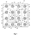
- the microfluid system 10 shown in FIG. 1 includes a microfluid chip 11. This comprises the substrate 12, into which a total of sixteen reservoirs 21 to 36 for the absorption of various fluid substances. There are twelve Reservoirs 21 to 32 for receiving the samples 41 to 52, a reservoir 33 for Inclusion of a buffer 53 serving as a separation medium and that with some buffer Pre-filled reservoirs 34, 35, 36 are provided for receiving waste 54, 55, 56.
- the reservoirs 21 to 36 are fluidly connected to one another by micro-channels form an open network with each other. This means that each of the Reservoirs 21 to 36 are in fluid communication with any other reservoir.
- opening channels in turn open in the area of one Transition point 66 into a single channel, which is in the area of a transfer point 68 divided into two channels.
- the first channel of these two channels opens into the Reservoir 34, which serves to hold the waste 54.
- the second channel of these two Channels open into the injection space of injection site 65, which is shown here as two intersecting channels with a total of four channel parts can be designed.
- There Channel 61 also opens. This opens at his from the injection room opposite end in the reservoir 33. This serves to accommodate the as Separating substance acting buffer 53.
- the junction of the channel 61 in the working channel 70 opens out opposite the injection chamber actual separation of the substances to be analyzed and in turn leads to the reservoir 35 for receiving the waste 55 after the analytical xxx detection site 69 happened.
- the injection space assigned to the injection site 65 is in the exemplary embodiment as a crossing point of the four described above Duct parts designed in this version each at an angle of 90 degrees are arranged offset to each other in a common plane, the each opposite channel parts in the case shown here to each other are aligned.
- Each reservoir 21 to 36 is contacted with an electrode 71 to 86.
- These serve for introducing or discharging electrical voltage and / or electrical current and can also serve as a measuring electrode according to the invention. With their help can be assigned to the current operating behavior of the microfluid system 10 electrical parameters recorded and a controller for regulating the driving force and / or a parameter that can be influenced thereby.
- electrokinetic forces are provided as the driving force, which by introducing or exerting electrical voltages across the electrodes 71 to 86 are introduced or transferred to the respective fluids 41 to 56 can, so that the fluids or components contained therein in the Users desired direction and speed through the open one Network-forming miniature channels can move.
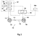
- the microfluid system 110 shown partially schematically in FIG. 2 is special simply designed. This figure also serves to represent the for control and Regulation of the force driving the fluid or the components contained therein and / or the parameters that can be influenced thereby.
- the microfluid system 110 has the one working channel 170 in which the fluid 141 and / or contained therein Components by means of a driving force, here one through the voltage source 188 generated electric or electrokinetic field in the direction (arrow 113) of the working channel 170 are movable.
- the reservoirs 121 and 135 are arranged, which are connected to the working channel 170 in Are in fluid communication.
- Each reservoir 121, 135 is each with an electrode 171 or 185 contacted for introducing or discharging electrical parameters.
- the fluid 141 or can the components contained in the direction (arrow 113) of the working channel 170 can be moved through this and can finally get into the reservoir 135 at its other end as waste 155.
- the Fluid 141 or the constituents contained thereon are essentially identical to one another constant speed through working channel 170 to move one to be able to carry out the most exact analysis possible.
- a characteristic parameter Self-mobility is the identification of a sample component. This material constant leads in connection with the operating parameters field strength and Viscosity of the separation medium at a characteristic speed.
- the effective resistance in the working channel and / or the Conductivity of the fluid 141 can change the power loss that occurs with the Consequence that when a substantially constant voltage is applied to the Electrodes 171 and 185, according to the prior art, depend on the internal and / or external disturbances in the interior of what is also referred to as the fluid thread Fluid flow sets a temperature that is different from the setpoint, so that the instantaneous speed of the sample components is determined by the viscosity in the separation channel depending on the internal and / or external disturbance variables. This can lead to correspondingly different migration speeds of the Lead fluids 141 and / or components contained therein, so that corresponding Errors in the analysis, here essentially in the identification, can occur.
- the electrode 185 is as Measuring electrode, i.e. as a sensor for measuring a fluid 141 assigned or coupled to the fluid 141 and derivable in the region of the fluid 141 Measured variable, here the electric current, provided.
- controller 192 With the sensor 185 is controller 192, here via electrical lines, is coupled.
- This controller 192 obeys a predetermined mathematical algorithm 193 and can also as programmable controller can be designed.
- the controller 192 is in turn one Device for changing the driving force 189, here the electrical Coupled voltage, which forms an actuator.
- the facility for change of the driving force 189 is coupled to the voltage source 188, which the supplies the necessary electrical voltage or the necessary electrical field.
- Control device 191 for controlling the device for changing the driving force connected according to certain preset parameters.
- the facility for change The driving force 189 is also provided with a controller 190 Provision of stabilized, i.e. essentially constant electrical Voltages or currents coupled, which in turn are electrically connected to electrode 171 is coupled.
- the controller 192 receives the current one from the control device 190 Status, which with the help of the predetermined mathematical algorithm 193 Knowledge of the measured current in a current deviation of the power loss and can thus be converted into a correction value.
- This correction value is used to control the device 189 for changing the driving force used.
- the current operating behavior of the Microfluidic system 110 to create a matching superimposed control loop with which it is possible, the power loss occurring and thus that in the fluid thread of the Working channel 170 occurring temperature increase independent of internal and / or to keep external disturbances essentially constant.
- the identification of the sample components can now be expected in anticipation of the constant Temperature conditions and knowing the measurable voltage difference on Separation channel through a time window.
- This time window calculated from the time the injection results from the corresponding mobility in the electrical field the distance in the separation channel from the injection point to the location of the detection.
- the voltage source 188, the device for changing the driving force 189, the control device 191 and the controller device 190 form the voltage supply unit 187. It goes without saying that such a voltage supply unit, at least the device for changing the driving force 189 and the Controller device 190, each or all electrodes 171, 185 even with one with more microfluid system designed as two electrodes, according to user needs can be used multiple times. In such a case the controller 192 also the respective status of that assigned to the electrode 185 Control device 190a supplied.
- the microfluidic system 210 is two, here rectangular intersecting channels designed, in turn with four channel parts 296, 297, 298th and 270 are designed. In the case shown here, the channel parts 296 and 270 are aligned and the channel parts 297 and 298, respectively. Otherwise, the channel parts 296, 297, 298 and 270 each at an angle of 90 degrees to each other in a common Level trained.
- the channel parts 296, 297, 298 and 270 intersect in the intersection 295, which is an injection space for the analyte Make a sample.
- a reservoir 233, 221 and 234 provided, each with the associated channel part in fluid communication stands.
- These reservoirs 221, 233, 234 are each provided with an electrode 271, 283, 284 contacted.
- the reservoir 221 takes the sample 241 to be analyzed and the reservoir 234 serves to receive the Waste 254.
- the reservoir 233 serves to hold the as a separating substance serving buffer 253.
- ESI electro-spray interface
- the Voltage generator 219 For the purpose of mass spectroscopic analysis, the Voltage generator 219 generates a so-called "ESI" voltage, which is used for Generation of the electro-spray 215 is used.
- the ESI voltage is usually from Adjustable to a specific mass spectrometer and the user to adapt to the given conditions. This voltage fluctuates from the device to device, or depending on the conditions of use.
- By means of the Voltage generator 219 generated electric field will be at the end of Channel 270 exiting fluid towards the probe 218 of the mass spectrometer accelerated.
- An electrical spray 215 can be generated in this way, which is a mass spectroscopic analysis of the sample to be analyzed allows.
- measuring electrode serving electrode in the area of the nozzle-side end of the working channel to arrange a control mechanism according to the Representation in connection with FIG. 2 or as follows in connection described with Fig. 4 to enable.
- a control mechanism according to the Representation in connection with FIG. 2 or as follows in connection described with Fig. 4 to enable.
- the use of measuring electrodes on or in the miniaturized microchannels is not uncritical and is not possible in many cases.
- electrolytic Processes and consequently oxidation of the electrodes occur, with the result changed contact resistance.
- the electrical parameters change and changed accordingly the voltage difference across the analysis section in the separation channel.
- Electrode 216 at that measuring point for certain electrical parameters created that is of interest it is proposed to To provide reference channel 299, which at the measuring point of interest in the Working channel 270 opens and then in at the opposite end known manner, a reservoir 237 for receiving a measuring liquid 294 is arranged. With the reservoir 237 is also in a known manner Measuring electrode 300 is contacted. It is understood that in particularly cheaper Embodiment of the invention for the aforementioned purposes already existing Channels and electrodes can be used effectively. By using it such reference channels with the formation of a virtual electrode at the measuring location consequently, the disadvantages described above can be avoided.
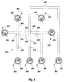
- the microfluid system 310 shown in FIG. 4 represents a partial section of the 1 and is otherwise similar to that Microfluid system 210 designed according to FIG. 3 designed channel parts.
- the Microfluidic system 310 includes a connection channel 401, which ends with the Reservoir 333 is fluid-connected in which the buffer 353 serving as a separating substance is included.
- the connection channel 401 opens at the injection site 365 an injection room. Three further channels open into this injection room, namely the two side channels 402 and 403 and the one here as a separation channel serving working channel 370.
- the working channel 370 points at its from the Injection site 365 facing away from a reservoir 335 for receiving the waste 355 on.
- Channel parts arranged symmetrically to the working channel 370. Penetrate it there are two channels at intersections, so that four each Channel parts flow into a common crossing area.
- Channels are the reservoirs 321, 322, 334 and the reservoirs 332, 336, 337 arranged fluidly connected.
- Each reservoir 321, 322, 332, 333, 334, 335, 336, 337 is contacted with an electrode 371, 372, 382, 383, 384, 385, 386, 397, those for introducing and / or discharging electrical parameters, in particular electrical ones Voltage and / or electrical current are used.
- reservoirs 321, 322 and 332 are samples 341, 342 and 352 and in reservoir 337 is in this case Reference liquid 394 added. It is understood that the reservoir 337 in can generally also be used to hold a sample liquid.
- a great advantage of being an open network of channels fluidly connected to each other ° designed microfluidic systems, microfluid chips in particular are particularly economical Working with a variety of different samples in a small space enable. It is therefore electrophoretic and / or electroosmotic Separation analyzes common that parallel to the separation analysis regarding a particular one Sample substance, for example sample 341, the next operation or the subsequent separation analysis is already prepared in such a way that in a so-called Preinjection phase the next sample, for example sample 352, to an in the smallest possible distance to the injection point 365 arranged transition point 367 is used.
- the reference channel 399 is provided, at the end of which is remote from the transition point 367 the reservoir 337 with the reference liquid 394 or another sample is arranged.
- a type of virtual electrode can be created at the transition point 367. This is achieved by first regulating the electric current (I 2 ) at the second electrode 397 acting as a measuring sensor to the value zero, so that in this way the electric voltage (U 2 ) at the second electrode 397 is measured or detected can be. Any electrical voltage (U 1 ) is applied to the first electrode 382, which is in contact with the reservoir 332 receiving the sample 352.
- the electrical voltage (U 1 ) on the first electrode 382 is then regulated to a voltage value increased by a predetermined voltage value of, for example, 200 volts.
- a predetermined voltage value for example, 200 volts.
- that voltage difference is selected as the predetermined voltage value, which has proven useful or necessary in preliminary tests for the movement of the fluid in question or the constituents contained therein in the intended time.
- the desired voltage difference can be kept essentially constant by means of the controller according to the embodiment shown in FIG. 2, by again the electrical voltage (U 2 ) is measured on the second electrode 397 designed as a measuring electrode and by proceeding in accordance with the steps described above.
- a parallel separation analysis in the separation and working channel 370 requires that certain electrical compensation currents 404 and 405 leading away from the injection site 365 in the direction of the side channels 402 and 403 be set.
- the procedure described above can be meaningfully supplemented in such a way that the electrical current (I 1 ) is also measured at the first electrode 382, then a desired current (I 3 set) at the third electrode 386 using a suitable one Algorithm is calculated, which in the exemplary embodiment is based on the application of Kirchhoff's law, according to which the sum of all currents is always zero and therefore constant.
- the target current (I 3 set) at the third electrode 386 is the sum of the current (I 1 ) measured at the first electrode 382 and a predetermined or predeterminable current (I 4 ) (arrow 404) in the same side channel 402, referred to as the fourth channel.
- the current intensity (l 3 ) at the third electrode 386 is then regulated to the value of the previously calculated target current intensity (I 3 target) by means of a further control device, not shown in the figures.
- the first electrode 382 consequently also serves as a measuring electrode for measuring the electric current (I 1 ).
- a substantially constant voltage can be set, as well as in the side channel 402, which connects the transition point 367 with the injection point 365, a substantially constant, predetermined electrical current I 4 (compensation current 404) can be set is necessary in order to be able to carry out the separation process which runs parallel to the pre-injection phase in the desired manner.
Abstract
Description
Die Erfindung betrifft ein Mikrofluid-System, insbesondere einen Mikrofluid-Chip, mit wenigstens einem Arbeitskanal, in dem ein Fluid und/oder darin enthaltene Bestandteile vermittels einer treibenden Kraft, insbesondere durch Anwendung von Druck, akustischer Energie, eines elektrischen und/oder eines magnetischen Feldes in Richtung des Arbeitskanals bewegbar sind und ein Verfahren zum Transport und der Führung eines Fluids und/oder darin enthaltener Bestandteile, in einem derartigen Mikrofluid-System.The invention relates to a microfluid system, in particular a microfluid chip at least one working channel in which a fluid and / or contained therein Components by means of a driving force, in particular by using Pressure, acoustic energy, an electrical and / or a magnetic field are movable in the direction of the working channel and a method for transport and the guidance of a fluid and / or components contained therein, in one such microfluid system.
Eine derartige Vorrichtung und ein derartiges Verfahren sind aus der US 5,965,001, der US 5,800,690 sowie aus der Zeitschrift Electrophoresis (2000), Seite 100 bis 106 sowie Seite 107 bis 115 vorbekannt. Der Inhalt dieser Dokumente wird an dieser Stelle zu beliebigen Zwecken in vollem Umfang aufgenommen, da in diesen Unterlagen wichtige Merkmale, insbesondere betreffend die konstruktive und werkstoffliche Ausbildung derartiger Mikrofluid-Systeme sowie betreffend mögliche Verfahren für den Transport und die Führung von Fluiden und/oder darin enthaltenen Bestandteilen in derartigen Mikrofluid-Systemen offenbart sind, also von Merkmalen, für die einzeln oder in Kombination untereinander, in Kombination mit den in dieser Anmeldung zusätzlich offenbarten Merkmalen Schutz beansprucht wird.Such a device and such a method are known from US 5,965,001, US 5,800,690 and from Electrophoresis (2000), pages 100-106 and pages 107 to 115 previously known. The content of these documents is attached to this Job fully included for any purpose, as in these Documents important features, especially regarding the constructive and material training of such microfluidic systems and possible ones Procedures for the transportation and management of fluids and / or contained therein Components in such microfluidic systems are disclosed, that is, features, for individually or in combination with each other, in combination with those in this Registration additional features disclosed protection is claimed.
Von besonderem Interesse sind derartige Mikrofluid-Systeme für Anwendungen im Bereich der Elektroosmose und/oder der Elektrophorese, wobei aus Gründen der Ökonomie und einem entsprechend größeren Anwendungsspektrum bevorzugt ein offenes Netzwerk von miteinander fluidverbundenen Miniaturkanälen eingesetzt wird. Dabei wird die Bewegung der individuellen Flüssigkeiten oder darin enthaltener Zellen, Organismen oder Bestandteile, wie Partikel oder Ionen oder neutrale Stoffe, bislang meist durch Ausübung elektrischer oder elektrokinetischer Kräfte, insbesondere durch elektrische Spannung, elektrischen Strom, elektrische Leistung oder durch andere elektrische Parameter kontrolliert. Diese elektrischen Kenngrößen werden üblicherweise mittels geeigneter Elektroden in das Fluid eingeleitet, die am jeweiligen Ende der sich teilweise kreuzenden Kanäle mit sogenannten Reservoirs kontaktiert sind, welche wiederum in Fluidverbindung mit den einzelnen Mikrokanälen stehen.Such microfluidic systems are of particular interest for applications in Field of electroosmosis and / or electrophoresis, for reasons of Economy and a correspondingly larger range of applications preferred open network of fluid-connected miniature channels is used. The movement of the individual liquids or contained therein Cells, organisms or components, such as particles or ions or neutral substances, hitherto mostly through the exercise of electrical or electrokinetic forces, in particular through electrical voltage, electrical current, electrical power or controlled by other electrical parameters. These electrical parameters are usually introduced into the fluid by means of suitable electrodes respective ends of the partially intersecting channels with so-called reservoirs are contacted, which in turn are in fluid communication with the individual microchannels stand.
Bislang wird in aufwendigen Vorversuchen eine sogenannte Methode oder ein "Assay" festgelegt, d.h. für ein gegebenes Mikrofluid-System, vorzugsweise einen Mikrofluid-Chip, werden bestimmte Reagenzien und eine bestimmte Datenauswertung und auch ein bestimmter zeitlicher Ablauf für die elektrischen Parameter, insbesondere die elektrische Stromstärke und/oder die elektrische Spannung bei bestimmten Temperaturen für jede Elektrode tabellarisch in einem sogenannten "Skript" festgelegt. Der Anwender wird schließlich in einem Protokoll über das Einsatzgebiet des jeweiligen Mikrofluid-Systems und dessen jeweilige Einsatzgrenzen informiert. In diesem Protokoll werden auch die Grenzen hinsichtlich der zu verwendenden Stoffe bzw. Fluide und deren Konzentrationen vorgegeben. Diese Grenzen müssen auch wegen der statisch in dem Skript festgelegten zeitinvarianten Parameter vergleichsweise eng definiert werden.So far, a so-called method or a has been used in complex preliminary tests "Assay" defined, i.e. for a given microfluidic system, preferably one Microfluidic chip, certain reagents and a certain data analysis and also a certain time sequence for the electrical parameters, in particular the electrical current and / or the electrical voltage certain temperatures for each electrode in a so-called table "Script" set. The user will eventually see a log of that Field of application of the respective microfluid system and its respective application limits informed. This protocol also defines the limits regarding the using substances or fluids and their concentrations. This Limits must also be due to the time invariant statically defined in the script Parameters are comparatively narrowly defined.
Entsprechend den in dem Skript definierten Parametern, werden bei der Versuchsdurchführung, also dem praktischen Einsatz des Mikrofluid-Systems, die elektrischen Parameter, insbesondere die elektrischen Ströme und/oder die elektrischen Spannungen an den einzelnen Elektroden in bestimmten Zeitabschnitten gestuft verändert, wobei spezielle elektrische Schaltungen, wie Strom- oder Spannungsregler sicherstellen, daß die jeweiligen elektrischen Parameter über den gewünschten Zeitraum an der jeweiligen Elektrode konstant gehalten werden.According to the parameters defined in the script, when carrying out the experiment, So the practical use of the microfluid system, the electrical Parameters, especially the electrical currents and / or the electrical ones Voltages at the individual electrodes are graded in certain time periods changed, with special electrical circuits, such as current or voltage regulator Make sure that the respective electrical parameters are above the desired Period of time at the respective electrode can be kept constant.
Es versteht sich, daß die Kontrolle der Bewegung der Flüssigkeiten und/oder der darin enthaltenen Bestandteile um so schwieriger wird, je komplexer das jeweilige Mikrofluid-System aufgebaut ist, d.h. je mehr miteinander fluidverbundene Mikro-Kanäle vorgesehen sind. So ist beispielsweise in einer relativ einfachen Anordnung von vier Kanälen, die an einem Punkt unter Ausbildung einer Kreuz-Verbindung fluidverbunden sind und wobei am Ende jeweils ein Reservoir und eine Elektrode vorgesehen sind, ein unabhängiger Anstieg der Fluidströmung zwischen zwei Reservoirs nicht nur durch eine Vergrößerung der Spannungsdifferenz an den beiden Reservoirs erzielbar. Die Spannungen an den anderen beiden Reservoirs müssen ebenfalls neu eingestellt werden, wenn der ursprüngliche Durchfluß und seine Richtung beibehalten werden soll. Folglich werden üblicherweise verschiedene elektrische Parameter gleichzeitig an mehreren Elektroden unterschiedlich, d.h. entsprechend dem jeweiligen Skript, eingestellt. Dabei unterliegen die Mikrofluid-Systeme sowohl inneren als auch äußeren Störgrößen, welche das Versuchsergebnis auch wegen des Durchgriffs auf die gegebenenfalls vorhandenen anderen Kanäle, erheblich beeinflussen können. Derartige Störgrößen können beispielsweise herstellungsbedingt durch geringe maßliche Abweichungen der Mikrofluid-Kanäle bedingt sein. Dabei bezieht sich der Term "Mikrofluid" auf Miniaturkanäle, die einen Querschnitt in der Größenordnung von 0,1 bis 500 µm aufweisen. Typische Abmessungen derartiger Miniaturkanäle betragen beispielsweise 15 µm Tiefe und 40 µm Breite. Die jeweilige Kanalgeometrie bestimmt ganz wesentlich den wirksamen Widerstand einer Flüssigkeit, so daß sich der Durchfluß und die elektrischen Kenngrößen bei einer Veränderung der Kanalgeometrie ebenfalls entsprechend verändern. Den Fertigungstoleranzen für die Fertigung derartiger Miniaturkanäle sind jedoch aus ökonomischen Gründen Grenzen gesetzt.It is understood that the control of the movement of the liquids and / or the The more complex the components are, the more difficult they become Microfluid system is constructed, i.e. the more fluid-connected micro-channels are provided. For example, in a relatively simple arrangement of four channels, which at one point form a cross-connection are fluid-connected and at the end each have a reservoir and an electrode are provided an independent increase in fluid flow between two Reservoirs not only by increasing the voltage difference across the achievable in both reservoirs. The tensions on the other two reservoirs must also be reset if the original flow and to keep its direction. As a result, usually different ones different electrical parameters simultaneously on several electrodes, i.e. according to the respective script. The microfluid systems are subject to this both internal and external disturbance variables, which the test result also because of the access to the others, if any Channels, can significantly influence. Such disturbances can, for example due to the manufacturing process due to slight dimensional deviations of the microfluid channels be conditional. The term "microfluid" refers to miniature channels that one Have cross-section in the order of 0.1 to 500 microns. typical Dimensions of such miniature channels are, for example, 15 µm deep and 40 µm width. The respective channel geometry essentially determines the effective one Resistance of a liquid, so that the flow and the electrical Characteristics when changing the channel geometry also corresponding change. The manufacturing tolerances for the manufacture of such miniature channels are however, there are limits for economic reasons.
Ferner können anwenderspezifische Schwankungen, beispielsweise durch unrichtige Auswahl und Vorbereitung von Fluiden oder Substanzen auftreten, deren Zusammensetzung, respektive Salzkonzentration, einen entsprechenden Einfluß auf die Leitfähigkeit der Versuchsfluide und dementsprechend der Leitfähigkeit in den einzelnen Kanälen hat, was ebenfalls unterschiedliche Durchflüsse oder Wanderungsgeschwindigkeiten von Stoffen durch veränderte elektrische Parameter zur Folge haben kann. Außerdem ist anwenderseitig zunehmend ein größeres Einsatzspektrum derartiger Mikrofluid-Systeme gewünscht, was bislang nur mit aufwendig zu ermittelnden unterschiedlichen "Skripten" oder gegebenenfalls gar nicht realisierbar ist.Furthermore, user-specific fluctuations, for example due to incorrect ones Selection and preparation of fluids or substances occur, their composition, respectively salt concentration, a corresponding influence on the Conductivity of the test fluids and, accordingly, the conductivity in the individual canals, which also have different flow rates or migration speeds of substances due to changed electrical parameters Can have consequences. In addition, the user is increasingly a larger one Spectrum of such microfluidic systems is desired, but so far only with different "scripts" that are difficult to determine, or possibly even is not feasible.
Schließlich ist es bei der quantitativen Bestimmung von Stoffen in einem Trennkanal oft von großer Wichtigkeit, daß die Wanderungsgeschwindigkeit des Fluids und/oder darin enthaltener Bestandteile, im wesentlichen konstant ist. Hierzu muß jedoch in dem für die Trennung vorgesehenen Abschnitt des Trennkanals über einen bestimmten Zeitraum eine im wesentlichen konstante Spannungsdifferenz aufrechterhalten werden. Gleiches gilt beispielsweise für ein Mikrofluid-System, bei dem während des Trennvorganges bereits eine weitere Probensubstanz in einem mit dem Trennkanal in Fluidverbindung stehenden Zuführkanal bis zu einer Übergabestelle "vorgezogen" bzw. "preinjiziert" wird, wobei die Übergabestelle in möglichst geringer Entfernung zum Trennkanal angeordnet ist. Auch dabei ist es von großer Wichtigkeit, daß innerhalb eines bestimmten Zeitraums, jedenfalls vor dem Abschluß des parallelen Trennvorganges, auch der langsamste Bestandteil in dem Fluid bis zum Übergabepunkt gelangt ist.After all, it is the quantitative determination of substances in a separation channel often of great importance that the rate of migration of the fluid and / or constituents contained therein is essentially constant. To do this, however, in the section of the separation channel provided for the separation via a maintain a substantially constant voltage difference for a certain period of time become. The same applies, for example, to a microfluid system in which during the separation process, another sample substance in one with the Separation channel in fluid communication feed channel to a transfer point is "brought forward" or "pre-injected", the transfer point being as low as possible Distance to the separation channel is arranged. It is also very important that within a certain period of time, at least before the close of the parallel separation process, also the slowest component in the fluid up to Transfer point has reached.
In beiden Fällen werden zeitgleich zum Trennvorgang bzw. zeitgleich zum Preinjiziervorgang, Additivströme in den Seitenkanälen der treibenden Spannung im Trennkanal bzw. dem Preinjizierkanal überlagert. Folglich kann bei Verwendung der vorgegebenen Skripte für die Versuchsdurchführung, abhängig von inneren oder äußeren Störgrößen, ein fehlerhaftes Versuchsergebnis resultieren.In both cases, at the same time as the separation process or at the same time as the pre-injection process, Additive currents in the side channels of the driving voltage in the Separation channel or the pre-injection channel superimposed. Consequently, when using the predefined scripts for carrying out the experiment, depending on inner or external disturbances, a faulty test result result.
Ein weiteres Problem bei der Anwendung von elektrokinetischen Kräften unter Verwendung von Elektroden ist es, daß diese nicht unmittelbar in bzw. an den Mikrokanälen des Mikrofluid-Systems eingesetzt werden können, da es an den Elektroden häufig zu einer unerwünschten Gasblasenbildung kommt. Diese Gasblasen können jedoch in den miniaturisierten Kanälen zu einer Erhöhung des wirksamen Widerstandes bis hin zu einem unendlich großen wirksamen Widerstand führen. Aus diesen Gründen werden die Elektroden üblicherweise mit Reservoirs verbunden, die ein vergleichsweise großes Fluid-Volumen aufnehmen können und die gegenüber der Geometrie der Miniaturkanäle deutlich größere Abmaße aufweisen. Dadurch ist jedoch der Einsatz der Elektroden auf das jeweilige Ende der Miniaturkanäle begrenzt. Für eine exakte und reproduzierbare Versuchsdurchführung sind jedoch häufig die elektrischen Parameter an den Kreuzungspunkten bzw. denjenigen Übergangsbereichen von Interesse, an denen die einzelnen Mikrofluidkanäle ineinander einmünden.Another problem with the application of electrokinetic forces The use of electrodes is that they are not directly in or on the Micro channels of the microfluid system can be used as it is connected to the Electrodes often leads to an undesirable gas bubble formation. This However, gas bubbles can increase the miniaturized channels effective resistance up to an infinitely large effective resistance to lead. For these reasons, the electrodes are usually made with reservoirs connected, which can accommodate a comparatively large volume of fluid and the significantly larger dimensions compared to the geometry of the miniature channels exhibit. However, this means that the electrodes are inserted at the respective end of the Miniature channels limited. For an exact and reproducible test execution however, the electrical parameters at the crossing points or those transition areas of interest in which the individual microfluidic channels flow into each other.
Es ist deshalb eine Aufgabe der Erfindung, ein Mikrofluid-System und ein Verfahren zum Transport und der Führung eines Fluids und/oder darin enthaltener Bestandteile in einem derartigen Mikrofluid-System zu schaffen, das ein breiteres Anwendungsund Einsatzspektrum und eine reduzierte Empfindlichkeit gegenüber inneren und/oder äußeren Störgrößen und folglich eine größere Betriebssicherheit ermöglicht.It is therefore an object of the invention, a microfluid system and a method for transporting and guiding a fluid and / or components contained therein in such a microfluidic system that has a wider application and Range of use and a reduced sensitivity to internal and / or external disturbance variables and consequently greater operational reliability.
Diese Aufgabe wird durch die Merkmale des Patentanspruches 1 insbesondere
dadurch gelöst, daß wenigstens ein Meßfühler zur Messung einer dem Fluid
zugeordneten oder an das Fluid gekoppelten und im Bereich des Fluids ableitbaren
Meßgröße und wenigstens ein Regler zur Regelung der treibenden Kraft und/oder
einer dadurch beeinflußbaren Kenngröße vorgesehen ist, wobei der Regler mit dem
Meßfühler und einer Einrichtung zur Veränderung der treibenden Kraft und/oder der
dadurch beeinflußbaren Kenngröße gekoppelt ist.This object is particularly by the features of
Durch diese Maßnahmen lassen sich die vorstehend beschriebenen Nachteile vermeiden. Insbesondere ist dadurch ein besserer Durchgriff auf das jeweilige Betriebsverhalten des einzelnen Mikrofluid-Systems möglich, indem auf innere und/oder äußere Störgrößen eine entsprechende Regelung der treibenden Kraft und/oder dadurch beeinflußbarer Kenngrößen und unter Anwendung jeweils geeigneter Algorithmen eine dynamische Sollwertanpassung realisiert werden kann. Auf diese Weise läßt sich auch ein breiteres Anwendungs- und Einsatzspektrum ermöglichen, weil sich das System beispielsweise auf anwenderspezifische Fehler bzw. bei einer Variation von vom Anwender bevorzugten Proben quasi von selbst anpaßt.The disadvantages described above can be eliminated by these measures avoid. In particular, this means better access to the respective one Operating behavior of the individual microfluid system possible by clicking on inner and / or external disturbances a corresponding regulation of the driving force and / or parameters that can be influenced thereby and using each suitable algorithms a dynamic setpoint adjustment can be realized. In this way, a wider range of applications and uses can be made enable because the system is based, for example, on user-specific errors or with a variation of samples preferred by the user almost automatically adapts.
Von besonderem Vorteil ist es, wenn mit dem Arbeitskanal wenigstens ein, in diesen einmündender Meßkanal fluidverbunden ist, der mit dem Meßfühler gekoppelt ist. Auf diese Weise lassen sich insbesondere an den bisher für den Einsatz von Elektroden ungeeigneten Kanal-Kreu-zungsstellen bzw. denjenigen Stellen, an denen ein oder mehrere Kanäle in ein oder mehrere andere Kanäle einmünden, geeignete Meßund/oder Eingriffsmöglichkeiten für die Ein- und/oder Ausleitung elektrischer Kenngrößen schaffen, indem dort quasi "virtuelle" Elektroden zur Verfügung gestellt werden. Zu diesem Zwecke kann sowohl ein an der gewünschten Stelle bereits existierender Miniaturkanal ausgenutzt werden, oder kann das Design des jeweiligen Mikrofluid-Systems in einfacher Weise dadurch geändert werden, daß ein weiterer Miniaturkanal vorgesehen wird, der an der gewünschten Meßstelle in einen oder in mehrere vorhandene Kanäle einmündet und der an seinem gegenüberliegenden Ende in Fluidverbindung mit einem geeigneten Reservoir steht, das wiederum mit einer Elektrode kontaktiert ist.It is particularly advantageous if there is at least one in the working channel opening measuring channel is fluidly connected, which is coupled to the sensor. On this way can be used in particular on the previously used electrodes unsuitable channel crossing points or those places where one or several channels open into one or more other channels, suitable measuring and / or Intervention options for the introduction and / or discharge of electrical Create parameters by making quasi "virtual" electrodes available there become. For this purpose, one can already be at the desired location existing miniature channel can be used, or the design of the respective Microfluidic system can be easily changed by adding another Miniature channel is provided, which at the desired measuring point in or in several existing channels open and the opposite one End is in fluid communication with a suitable reservoir, which in turn with an electrode is contacted.
Zweckmäßigerweise ist das Mikrofluid-System mit einem offenen Netzwerk von miteinander fluidverbundenen Kanälen ausgebildet, wobei wenigstens drei, vorzugsweise vier der Kanäle in einen gemeinsamen, insbesondere punktartig ausgebildeten Kanalraum einmünden, wobei einer der Kanäle als Meßkanal fungiert. Im Rahmen einer derartigen Drei- bzw. Vierkanaltechnik lassen sich besonders günstig über den Meßkanal bzw. die Meßkanäle regelbare Stoffflüsse erreichen, welche die Anwendung von ökonomisch handhabbaren Regelalgorithmen ermöglichen und die ein erheblich verbreitetes Anwendungs- und Einsatzspektrum derartiger Mikrofluid-Systeme ermöglichen.The microfluid system is expediently provided with an open network of channels fluidly connected to one another, at least three, preferably four of the channels in a common, in particular point-like formed channel space open, wherein one of the channels acts as a measuring channel. In the context of such a three- or four-channel technology, it is particularly possible to: achieve controllable material flows favorably via the measuring channel or channels, which enable the use of economically manageable control algorithms and which has a considerably widespread application and use spectrum of such Enable microfluidic systems.
Gemäß einer zweckmäßigen Weiterbildung der Erfindung steht der Arbeitskanal mit wenigstens zwei Elektroden zur Ausübung eines elektrischen und/oder magnetischen Feldes auf das Fluid in Verbindung, wobei wenigstens eine Arbeitselektrode mit elektrischem Strom und/oder elektrischer Spannung beaufschlagbar ist und wobei wenigstens eine Meßelektrode als Meßfühler dient. Diese Anordnung hat sich insbesondere für eine auf das aktuelle Betriebsverhalten abgestimmte Regelung von Fluidprozessen bei Anwendung von Mikrofluidsystemen im Bereich der Elektroosmose oder der Elektrophorese als vorteilhaft erwiesen.According to an expedient development of the invention, the working channel is provided at least two electrodes for exercising an electrical and / or magnetic Field connected to the fluid, with at least one working electrode can be acted upon with electrical current and / or electrical voltage and wherein at least one measuring electrode serves as a sensor. This arrangement has changed in particular for a regulation of Fluid processes when using microfluidic systems in the field of electroosmosis or electrophoresis has proven to be advantageous.
Dabei ist es besonders zweckmäßig, wenn alle Elektroden sowohl als Arbeitselektrode als auch als Meßelektrode einsetzbar sind bzw. eingesetzt werden. Dadurch wird das Anwendungs- und Einsatzspektrum bestehender Mikrofluid-Systeme vorteilhaft erweitert, in dem an beliebigen, mit Arbeitselektroden versehenen Kanalstellen nunmehr auch die für eine günstige Regelung der Stoffflüsse geeigneten Meßfühler zur Verfügung stehen.It is particularly useful if all electrodes are both working electrodes can also be used as a measuring electrode. This will the range of applications and uses of existing microfluidic systems is advantageous extended, in any channel point provided with working electrodes now also the sensors suitable for a favorable regulation of the material flows be available.
Die vorstehende Aufgabe wird auch durch ein Verfahren zum Transport und der Führung eines Fluids und/oder darin enthaltener Bestandteile in einem Mikrofluid-System, insbesondere einem Mikrofluid-Chip, mit wenigstens einem Arbeitskanal, in dem das Fluid und/oder darin enthaltene Bestandteile vermittels einer treibenden Kraft, insbesondere durch Anwendung von Druck, akustischer Energie, eines elektrischen und/oder eines magnetischen Feldes in Richtung des Arbeitskanals bewegt wird, gelöst, wobei ein mit einem Meßfühler zur Messung einer dem Fluid zugeordneten und im Bereich des Fluids ableitbaren Meßgröße und einer Einrichtung zur Veränderung der treibenden Kraft und/oder einer dadurch beeinflußbaren Kenngröße gekoppelter Regler die treibende Kraft und/oder die dadurch beeinflußbare Kenngröße regelt.The above task is also accomplished by a method of transportation and the Guidance of a fluid and / or components contained therein in a microfluid system, in particular a microfluid chip, with at least one working channel, in which the fluid and / or components contained therein by means of a driving Force, especially by applying pressure, acoustic energy, one electrical and / or a magnetic field in the direction of the working channel is moved, solved, one with a sensor for measuring a the fluid assigned measurement variable and a device that can be derived in the region of the fluid to change the driving force and / or an influence thereby Characteristic of coupled controllers, the driving force and / or the influence that can be influenced thereby Characteristic regulates.
Zweckmäßigerweise regelt der Regler die treibende Kraft und/oder die dadurch beeinflußbare Kenngröße derart, daß diese insbesondere unabhängig von inneren und/oder äußeren Störgrößen im wesentlichen konstant gehalten wird bzw. werden, so daß eine größere Betriebssicherheit und ein größeres Anwendungs-Einsatzspektrum ermöglicht sind. Mit "konstant" ist im Rahmen der Offenbarung dieses Schutzrechts nicht nur ein über der Zeit gleichbleibender absoluter Kennwert gemeint, sondern eine beliebige Kennwertfunktion über der Zeit, also beispielsweise ein "Gradient" oder eine "Rampe", die aber durch die erfindungsgemäße Regelung invariant in Reaktion auf innere oder äußere Störeinflüße gehalten wird.The controller expediently regulates the driving force and / or thereby parameter that can be influenced in such a way that it is particularly independent of internal parameters and / or external disturbance variables are kept essentially constant, so that greater operational reliability and a wider range of applications are possible. With "constant" is within the scope of the revelation this property right is not just an absolute characteristic value that remains constant over time meant, but an arbitrary characteristic function over time, for example a "gradient" or a "ramp", but this is due to the regulation according to the invention is kept invariant in response to internal or external interference.
Von besonderem Vorteil ist es, wenn der Regler die treibende Kraft und/oder die dadurch beeinflußbare Kenngröße derart regelt, daß der Gradient der treibenden Kraft und/oder der Gradient der durch die treibende Kraft beeinflußbaren Kenngröße über einen bestimmten Abschnitt des Arbeitskanals, insbesondere unabhängig von inneren und/oder äußeren Störgrößen, im wesentlichen konstant gehalten wird bzw. werden. Auf diese Weise läßt sich in dem Arbeitskanal eine im wesentlichen konstante Geschwindigkeit bzw. ein im wesentlichen konstanter Durchfluß des Fluids und/oder darin enthaltener Bestandteile erreichen, was für viele Anwendungen, insbesondere für Anwendungen im Bereich der Trennanalyse interessant ist.It is particularly advantageous if the controller has the driving force and / or the thereby influencing parameter regulates such that the gradient of the driving Force and / or the gradient of the parameter that can be influenced by the driving force over a certain section of the working channel, especially regardless of internal and / or external disturbance variables is kept essentially constant or become. In this way, one can essentially in the working channel constant speed or a substantially constant flow of the fluid and / or components contained therein, which for many applications, is particularly interesting for applications in the field of separation analysis.
Es ist ferner vorteilhaft, wenn der Regler die treibende Kraft und/oder die dadurch beeinflußbare Kenngröße dergestalt regelt, daß eine im wesentlichen konstante oder vorbestimmte joulesche Verlustleistung erreicht wird, so daß die in dem Fluidfaden des Arbeitskanals auftretende Temperatur konstant gehalten wird oder die Temperaturerhöhung bestimmbar ist und folglich einer weiteren rechnerischen Auswertung zuführbar ist. Dabei ist es zweckmäßig, wenn die Regelung bzw. die Identifikation der Probenbestandteile abhängig von der Eigenmobilität im Zusammenhang mit der am Trennkanal angelegten Differenzspannung erfolgt, um bei auftretenden Leitfähigkeitsveränderungen eine Identifikation der Probenbestandteile über deren Eigenmobilität zu ermöglichen.It is also advantageous if the controller is the driving force and / or the result influenceable parameter regulates such that an essentially constant or predetermined Joule power loss is reached, so that in the fluid filament the temperature of the working channel is kept constant or the Temperature increase can be determined and consequently another arithmetical Evaluation can be supplied. It is useful if the regulation or Identification of the sample components depending on their own mobility in connection with the differential voltage applied to the isolation channel in order to occurring conductivity changes an identification of the sample components through their own mobility.
Von besonderem Vorteil ist es, wenn bei dem als offenes Netzwerk von miteinander fluidverbundenen Kanälen ausgebildeten Mikrofluid-System mehrere Kanäle in einen gemeinsamen, insbesondere punktartig ausgebildeten Kanalraum einmünden, wobei wenigstens einer der Kanäle als Meßkanal fungiert, und wobei die Kanäle an ihrem jeweiligen, von dem Kanalraum entfernten Ende, jeweils mit einer Elektrode zur Ausübung eines elektrischen Feldes auf das Fluid kontaktiert sind, und wobei die Elektroden mit elektrischem Strom und/oder elektrischer Spannung beaufschlagbar sind, und wobei einem ersten Kanal eine erste Elektrode und einem zweiten Kanal eine zweite Elektrode zugeordnet ist, gekennzeichnet durch die folgenden Schritte:
- a)
- Regelung des elektrischen Stromes (I2) an der zweiten, als Meßfühler fungierenden Elektrode auf den Wert Null;
- b)
- Messen der elektrischen Spannung (U2) an der zweiten Elektrode, wobei an der ersten Elektrode eine beliebige Spannung (U1) angelegt ist;
- c)
- Regelung der elektrischen Spannung (U1) an der ersten Elektrode dergestalt, daß die Differenz zwischen U1 und U2 einen vorbestimmten Wert erreicht.
- a)
- Regulation of the electrical current (I 2 ) on the second electrode, which acts as a measuring sensor, to the value zero;
- b)
- Measuring the electrical voltage (U 2 ) on the second electrode, any voltage (U 1 ) being applied to the first electrode;
- c)
- Regulation of the electrical voltage (U 1 ) on the first electrode such that the difference between U 1 and U 2 reaches a predetermined value.
Auf diese Weise lassen sich derartige Mikrofluid-Systeme bei Anwendungen auf dem Gebiet der Kapillarelektrophorese, der Flüssigkeitskromatographie und bei chemischen Reaktionen, insbesondere bei DNA/RNA-Assays oder Protein-Assays mit einer höheren Betriebssicherheit gegenüber inneren und/oder äußeren Störgrößen und bei einem erweiterten Anwendungs- und Einsatzspektrum einsetzen, die auch den aktuellen und den zukünftigen Anwenderbedürfnissen bei gleichbleibend hoher Qualität der Analysenergebnisse auch über einen langen Zeitraum genügen.In this way, such microfluidic systems can be used in applications on the Field of capillary electrophoresis, liquid chromatography and chemical reactions, especially in DNA / RNA assays or protein assays with a higher level of operational reliability compared to internal and / or external Use disturbances and with an extended range of applications and uses, which also the current and future user needs at the same high quality of the analysis results even over a long period of time suffice.
Dabei ist es ferner zweckmäßig, daß bei dem als offenes Netzwerk von miteinander fluidverbundenen Kanälen ausgebildeten Mikrofluid-System wenigstens vier Kanäle in einen gemeinsamen, insbesondere punktartig ausgebildeten Kanalraum einmünden, wobei wenigstens einer der Kanäle als Meßkanal fungiert, und wobei wenigstens drei der Kanäle an ihrem jeweiligen, von dem Kanalraum entfernten Ende, jeweils mit einer Elektrode zur Ausübung eines elektrischen Feldes auf das Fluid kontaktiert sind, und wobei die Elektroden mit elektrischem Strom und/oder elektrischer Spannung beaufschlagbar sind, und wobei dem ersten Kanal eine erste Elektrode. dem zweiten Kanal eine zweite Elektrode und dem dritten Kanal eine dritte Elektrode zugeordnet ist, gekennzeichnet durch die folgenden Schritte:
- a)
- Regelung des elektrischen Stromes (I2) an der zweiten, als Meßfühler fungierenden Elektrode auf den Wert Null;
- b)
- Messen der elektrischen Spannung (U2)an der zweiten Elektrode, wobei an der ersten Elektrode eine beliebige Spannung (U1)angelegt ist;
- c)
- Regelung der elektrischen Spannung (U1) an der ersten Elektrode dergestalt, daß die Differenz zwischen U1 und U2 einen vorbestimmten Wert erreicht;
- d)
- Messen der elektrischen Stromstärke (I1) an der ersten Elektrode;
- e)
- Berechnen einer Soll-Stromstärke (I3-Soll) an der dritten Elektrode als Summe der an der ersten Elektrode gemessenen Stromstärke (I1) und einer vorbestimmten, dem vierten Kanal zugeordneten Stromstärke (I4);
- f)
- Regelung der Stromstärke (l3) an der dritten Elektrode auf den Wert der zuvor berechneten Soll-Stromstärke (I3-Soll);
- g)
- Wiederholung der Schritte b) bis f).
- a)
- Regulation of the electrical current (I 2 ) on the second electrode, which acts as a measuring sensor, to the value zero;
- b)
- Measuring the electrical voltage (U 2 ) on the second electrode, any voltage (U 1 ) being applied to the first electrode;
- c)
- Regulation of the electrical voltage (U 1 ) on the first electrode such that the difference between U 1 and U 2 reaches a predetermined value;
- d)
- Measuring the electrical current intensity (I 1 ) at the first electrode;
- e)
- Calculating a target current (I 3 target) at the third electrode as the sum of the current (I 1 ) measured at the first electrode and a predetermined current (I 4 ) assigned to the fourth channel;
- f)
- Regulation of the current (l 3 ) on the third electrode to the value of the previously calculated target current (I 3 target);
- G)
- Repeat steps b) to f).
Auf diese Weise lassen sich die vorstehend bezeichneten Vorteile auch in hochkomplexen, auf der Vierkanaltechnik basierenden Mikrofluid-Systemen unter Anwendung eines einfachen mathematischen Algorithmus erreichen.In this way, the advantages described above can also be achieved in highly complex, using microfluidic systems based on four-channel technology of a simple mathematical algorithm.
Gemäß einer vorteilhaften Weiterbildung der Erfindung führen bei dem als offenes Netzwerk von miteinander fluidverbundenen Kanälen ausgebildeten Mikrofluid-System wenigstens zwei Kanäle zu einem gemeinsamen ESI- (Electro-Spray-Interface) -punkt, wobei wenigstens zwei der Kanäle an ihrem jeweiligen, von dem gemeinsamen Kanalraum entfernten Ende, jeweils mit einer Elektrode zur Ausübung eines elektrischen Feldes auf das Fluid kontaktiert sind, und wobei die Elektroden mit elektrischem Strom und/oder elektrischer Spannung beaufschlagbar sind, und wobei die Summe des elektrischen Stromes in dem gesamten Mikrofluid-System dergestalt geregelt wird, daß gemäß dem Kirchhoffschen Gesetz ein bestimmter ESI-Reststrom verbleibt.According to an advantageous further development of the invention, this leads to an open one Network of microfluidic system formed by fluid-connected channels at least two channels to a common ESI (Electro Spray Interface) -point, with at least two of the channels at their respective, from which common channel space distal end, each with an electrode for exercise an electrical field on the fluid are contacted, and wherein the electrodes with electrical current and / or electrical voltage can be applied, and wherein the sum of the electrical current in the entire microfluidic system it is regulated that according to Kirchhoff's law a certain residual ESI current remains.
Vorstehende Merkmale tragen sowohl einzeln als auch in Kombination untereinander zu einem Mikrofluid-System bzw. einem Verfahren zum Transport und der Führung eines Fluids und/oder darin enthaltener Bestandteile in einem derartigen Mikrofluid-System bei, das ein breiteres Anwendungs- und Einsatzspektrum und eine verringerte Empfindlichkeit gegenüber inneren und/oder äußeren Störgrößen und folglich eine größere Betriebssicherheit ermöglicht.The above features bear both individually and in combination with one another to a microfluid system or a method for transport and guidance of a fluid and / or constituents contained therein in such a microfluid system with a wider range of applications and uses and a reduced sensitivity to internal and / or external disturbances and consequently allows greater operational security.
Weitere Merkmale, Gesichtspunkte und Vorteile der Erfindung sind dem nachfolgenden, anhand der Figuren abgehandelten Beschreibungsteil entnehmbar, in dem bevorzugte Ausführungsbeispiele der Erfindung beschrieben sind.Further features, aspects and advantages of the invention are the following, on the basis of the figures dealt with in the description part, in which preferred embodiments of the invention are described.
Es zeigen:
- Fig. 1
- ein erfindungsgemäßes Mikrofluid-System in Form eines Mikrofluid-Chips mit insgesamt 16 Reservoirs zur Aufnahme von fluiden Substanzen, wobei diese Reservoirs mit einem offenen Netzwerk von Mikrokanälen in Fluidverbindung stehen und mit einem als Arbeitskanal dienenden Trennkanal, das insbesondere in der elektrophoretischen Flüssigkeitsänalyse einsetzbar ist;
- Fig. 2
- eine schematische Darstellung eines einfach aufgebauten Mikrofluid-Systems gemäß der Erfindung, mit Darstellung der für die Steuerung und Regelung der hier elektrischen bzw. elektrokinetischen Prozesse erforderlichen Einrichtungen;
- Fig. 3
- ein weiteres Mikrofluid-System gemäß einer bevorzugten Ausführungsform der Erfindung unter Verwendung eines Referenzkanals und unter Ausbildung einer virtuellen Elektrode am Beispiel einer massenspektrometrischen Analysenanwendung;
- Fig. 4
- ein weiteres Mikrofluid-System mit einem Netzwerk von untereinander fluidverbundenen Mikrokanälen und unter Verwendung eines mit einer Meßelektrode kontaktierten Referenzkanals zur Erläuterung einer besonders vorteilhaften Verfahrensweise.
- Fig. 1
- an inventive microfluid system in the form of a microfluid chip with a total of 16 reservoirs for receiving fluid substances, these reservoirs being in fluid communication with an open network of microchannels and with a separation channel serving as a working channel, which can be used in particular in electrophoretic liquid analysis;
- Fig. 2
- is a schematic representation of a simply constructed microfluid system according to the invention, showing the facilities required for the control and regulation of the electrical or electrokinetic processes here;
- Fig. 3
- a further microfluid system according to a preferred embodiment of the invention using a reference channel and forming a virtual electrode using the example of a mass spectrometric analysis application;
- Fig. 4
- a further microfluid system with a network of mutually fluid-connected microchannels and using a reference channel contacted with a measuring electrode to explain a particularly advantageous procedure.
Das in Fig. 1 gezeigte Mikrofluid-System 10 beinhaltet einen Mikrofluid-Chip 11.
Dieser umfaßt das Substrat 12, in das hier insgesamt sechzehn Reservoirs 21 bis 36
zur Aufnahme von diversen fluiden Substanzen aufgenommen sind. Dabei sind zwölf
Reservoirs 21 bis 32 zur Aufnahme der Proben 41 bis 52, ein Reservoir 33 zur
Aufnahme eines als Trennmedium dienenden Puffers 53 sowie die mit etwas Puffer
vorgefüllten Reservoirs 34, 35, 36 zur Aufnahme von Abfall 54, 55, 56 vorgesehen.
Die Reservoirs 21 bis 36 sind untereinander durch Mikro-Kanäle fluidverbunden, die
miteinander ein offenes Netzwerk ausbilden. Dies bedeutet, daß jedes der
Reservoirs 21 bis 36 in Fluidverbindung mit jedem anderen Reservoir steht. Die in
die Reservoirs 21 bis 32 mündenden Kanäle münden wiederum im Bereich einer
Übergangsstelle 66 in einen einzigen Kanal, der sich im Bereich einer Übergabestelle
68 in zwei Kanäle aufteilt. Der erste Kanal dieser beiden Kanäle mündet in das
Reservoir 34, das zur Aufnahme des Abfalls 54 dient. Der zweite Kanal dieser beiden
Kanäle mündet in den Injektionsraum der Injektionsstelle 65, die wie hier gezeigt als
zwei sich kreuzende Kanäle mit insgesamt vier Kanal-Teilen gestaltet sein kann. Dort
mündet auch der Kanal 61 ein. Dieser mündet an seinem von dem Injektionsraum
abgewandten Ende in das Reservoir 33. Dieses dient zur Aufnahme des als
Trennsubstanz fungierenden Puffers 53. Der Einmündungsstelle des Kanals 61 in
den Injektionsraum gegenüberliegend mündet der Arbeitskanal 70. Dieser dient zur
eigentlichen Trennung der zu analysierenden Substanzen und mündet wiederum in
das Reservoir 35 zur Aufnahme des Abfalls 55 nachdem die analytische xxxDetektionstelle
69 passiert wurde. Der der Injektionsstelle 65 zugeordnete Injektionsraum ist
im Ausführungsbeispiel als Kreuzungspunkt der vorstehend beschriebenen vier
Kanal-Teile gestaltet, die in dieser Ausführung jeweils um einen Winkel von 90 Grad
versetzt zueinander in einer gemeinsamen Ebene angeordnet sind, wobei die sich
jeweils gegenüberliegenden Kanalteile in dem hier gezeigten Fall zueinander
fluchtend angeordnet sind. The
Jedes Reservoir 21 bis 36 ist mit einer Elektrode 71 bis 86 kontaktiert. Diese dienen
zur Ein- bzw. Ausleitung von elektrischer Spannung und/oder elektrischem Strom
und können gemäß der Erfindung zugleich als Meßelektrode dienen. Mit deren Hilfe
können dem aktuellen Betriebsverhalten des Mikrofluid-Systems 10 zugeordnete
elektrische Parameter erfaßt und einem Regler zur Regelung der treibenden Kraft
und/oder einer dadurch beeinflußbaren Kenngröße zugeführt werden. Im Ausführungsbeispiel
sind als treibende Kraft elektrokinetische Kräfte vorgesehen, welche
durch Einleitung bzw. Ausübung von elektrischen Spannungen über die Elektroden
71 bis 86 auf die jeweiligen Fluide 41 bis 56 eingeleitet bzw. übertragen werden
können, so daß sich die Fluide bzw. darin enthaltene Bestandteile in der vom
Anwender gewünschten Richtung und Geschwindigkeit durch die ein offenes
Netzwerk bildenden Miniaturkanäle bewegen können.Each reservoir 21 to 36 is contacted with an
Das in Fig. 2 teilweise schematisch gezeigte Mikrofluid-System 110 ist besonders
einfach gestaltet. Diese Figur dient auch zur Darstellung der für die Steuerung und
Regelung der das Fluid bzw. die darin enthaltenen Bestandteile treibenden Kraft
und/oder der dadurch beeinflußbaren Kenngrößen. Das Mikrofluid-System 110 weist
den einen Arbeitskanal 170 auf, in dem das Fluid 141 und/oder darin enthaltene
Bestandteile vermittels einer treibenden Kraft, hier eines durch die Spannungsquelle
188 erzeugten elektrischen bzw. elektrokinetischen Feldes in Richtung (Pfeil 113)
des Arbeitskanals 170 bewegbar sind. An den jeweiligen Enden des Arbeitskanals
170 sind die Reservoirs 121 und 135 angeordnet, die mit dem Arbeitskanal 170 in
Fluidverbindung stehen. Jedes Reservoir 121, 135 ist jeweils mit einer Elektrode 171
bzw. 185 zur Ein- bzw. Ausleitung von elektrischen Kenngrößen kontaktiert. Unter
Anlegung einer elektrischen Spannung an die Elektrode 171 kann das Fluid 141 bzw.
können die darin enthaltenen Bestandteile in Richtung (Pfeil 113) des Arbeitskanals
170 durch diesen hindurchbewegt werden und kann bzw. können schließlich an
seinem anderen Ende als Abfall 155 in das Reservoir 135 gelangen. Bei der
Trennanalyse in dem Arbeitskanal 170 ist es von besonderer Wichtigkeit, daß das
Fluid 141 bzw. die daran enthaltenem Bestandteile sich mit einer im wesentlichen
konstanten Geschwindigkeit durch den Arbeitskanal 170 bewegen, um eine
möglichst exakte Analyse vornehmen zu können. Ein charakteristischer Parameter
zur Identifikation eines Probenbestandteiles ist die Eigenmobilität. Diese Stoffkonstante
führt im Zusammenhang mit den Betriebsparametern Feldstärke und
Viskosität des Trennmediums zu einer charakteristischen Geschwindigkeit. Da die
Viskosität des Trennmediums aber stark temperaturabhängig ist, ergibt sich das
Bedürfnis, die der Flüssigkeit im Trennkanal zugeordnete Temperatur exakt zu
bestimmen oder zu beeinflussen. Während die Außenfläche des Mikrofluid-Chips mit
geeigneten Mitteln auf eine gewünschte Temperatur gebracht werden kann, ist durch
das Auftreten der "joule-schen Verlustleistung" im Innern des Fluids eine erhöhte
Temperatur gegeben, die aber auf Grund der miniaturisierten Geometrie nicht
gemessen werden kann. Zu diesem Zwecke ist es vorteilhaft, die auftretende
Verlustleistung unabhängig von inneren und äußeren Störeinflüssen konstant zu
halten. Reproduzierbare Betriebsbedingungen, und damit Ergebnisse, sind somit
erreichbar. Abhängig vom wirksamen Widerstand im Arbeitskanal und/oder der
Leitfähigkeit des Fluids 141 kann sich die auftretende Verlustleistung ändern, mit der
Folge, daß bei Anlegung einer im wesentlichen konstanten Spannung an den
Elektroden 171 und 185, gemäß dem Stand der Technik, sich abhängig von den
inneren und/oder äußeren Störgrößen im Innern des auch als Fluidfaden bezeichneten
Fluidstromes eine gegenüber dem Sollwert veränderte Temperatur einstellt, so
daß sich über die Viskosität die Momentangeschwindigkeit der Probenbestandteile
im Trennkanal abhängig von den inneren und/oder äußeren Störgrößen ausbildet.
Dies kann zu entsprechend unterschiedlichen Wanderungsgeschwindigkeiten des
Fluids 141 und/oder darin enthaltener Bestandteile führen, so daß entsprechende
Fehler bei der Analyse, hier im wesentlichen bei der Identifikation, auftreten können.The
Zur Vermeidung der vorstehend beschriebenen Nachteile ist die Elektrode 185 als
Meßelektrode, d.h. als Meßfühler zur Messung einer dem Fluid 141 zugeordneten
bzw. an das Fluid 141 gekoppelten und im Bereich des Fluids 141 ableitbaren
Meßgröße, hier des elektrischen Stromes, vorgesehen. Mit dem Meßfühler 185 ist
der Regler 192, hier über elektrische Leitungen, gekoppelt. Dieser Regler 192
gehorcht einem vorbestimmten mathematischen Algorithmus 193 und kann auch als
programmierbarer Regler gestaltet sein. Der Regler 192 ist seinerseits mit einer
Einrichtung zur Veränderung der treibenden Kraft 189, hier der elektrischen
Spannung gekoppelt, welche ein Stellglied ausbildet. Die Einrichtung zur Veränderung
der treibenden Kraft 189 ist mit der Spannungsquelle 188 gekoppelt, welche die
notwendige elektrische Spannung bzw. das notwendige elektrische Feld liefert. Mit
der Einrichtung zur Veränderung der treibenden Kraft 189 ist wiederum eine
Steuereinrichtung 191 zur Steuerung der Einrichtung zur Veränderung der
treibenden Kraft nach bestimmten voreingestellten Parametern verbunden. Dabei
kann es sich um die gemäß dem Stand der Technik in einem sogenannten "Skript"
festgelegten Parameter handeln. Diese können auch in einer Speichereinheit,
beispielsweise einem RAM bzw. ROM abgelegt sein. Die Einrichtung zur Veränderung
der treibenden Kraft 189 ist ferner mit einer Reglereinrichtung 190 zur
Bereitstellung von stabilisierten, d.h. im wesentlichen konstanten elektrischen
Spannungen oder Strömen gekoppelt, die wiederum mit der Elektrode 171 elektrisch
gekoppelt ist. Der Regler 192 erhält von der Regeleinrichtung 190 den aktuellen
Status, welcher mit Hilfe des vorbestimmten mathematischen Algorithmus 193 mit
Kenntnis des gemessenen Stromes in eine aktuelle Abweichung der Verlustleistung
und damit in einen Korrekturwert umgerechnet werden kann. Dieser Korrekturwert
wird zur Steuerung der Einrichtung 189 zur Veränderung der treibenden Kraft
verwendet. Auf diese Weise läßt sich ein sich an das aktuelle Betriebsverhalten des
Mikrofluid-Systems 110 anpassender überlagerter Regelkreis schaffen, mit dem es
möglich ist, die auftretende Verlustleistung und damit die im Fluidfaden des
Arbeitskanals 170 auftretende Temperaturerhöhung unabhängig von inneren
und/oder äußeren Störgrößen im wesentlichen konstant zu halten.To avoid the disadvantages described above, the
Die Identifikation der Probenbestandteile kann nun in Erwartung der konstanten Temperaturverhältnisse und in Kenntnis der meßbaren Spannungdifferenz am Trennkanal durch ein Zeitfenster erfolgen. Dieses Zeitfenster, gerechnet ab Zeitpunkt der Einspritzung, ergibt sich aus der entsprechenden Mobilität im elektrischen Feld über die Entfernung im Trennkanal vom Einspritzpunkt bis zum Ort der Detektion.The identification of the sample components can now be expected in anticipation of the constant Temperature conditions and knowing the measurable voltage difference on Separation channel through a time window. This time window, calculated from the time the injection results from the corresponding mobility in the electrical field the distance in the separation channel from the injection point to the location of the detection.
Die Spannungsquelle 188, die Einrichtung zur Veränderung der treibenden Kraft 189,
die Steuereinrichtung 191 und die Reglereinrichtung 190 bilden die Spannungsversorgungseinheit
187. Es versteht sich, daß eine derartige Spannungsversorgungseinheit,
zumindest die Einrichtung zur Veränderung der treibenden Kraft 189 und die
Reglereinrichtung 190, jeder bzw. allen Elektroden 171, 185 auch bei einem mit mehr
als zwei Elektroden ausgebildeten Mikrofluid-System, entsprechend den Anwenderbedürfnissen
beliebig mehrfach eingesetzt werden kann. In einem solchen Fall wird
dem Regler 192 auch der jeweilige Status von der der Elektrode 185 zugeordneten
Regeleinrichtung 190a zugeführt. The
Die Fig. 3 zeigt ein weiteres Mikrofluid-System, wie es für eine massenspektroskopische
Analyse von fluiden Substanzen und/oder darin enthaltener Bestandteile
eingesetzt werden kann. Das Mikrofluid-System 210 ist mit zwei, sich hier rechtwinklig
kreuzenden Kanälen gestaltet, die wiederum mit vier Kanalteilen 296, 297, 298
und 270 gestaltet sind. In dem hier gezeigten Fall fluchten die Kanalteile 296 und 270
sowie die Kanalteile 297 und 298 jeweils. Im übrigen sind die Kanalteile 296, 297,
298 und 270 jeweils in einem Winkel von hier 90 Grad zueinander in einer gemeinsamen
Ebene ausgebildet. Dabei kreuzen sich die Kanalteile 296, 297, 298 und 270
in der Kreuzungsstelle 295, welche einen Injektionsraum für die zu analysierende
Probe bilden. Am Ende der Kanalteile 296, 297 und 298 ist jeweils ein Reservoir 233,
221 und 234 vorgesehen, das jeweils mit dem zugehörigen Kanalteil in Fluidverbindung
steht. Diese Reservoirs 221, 233, 234 sind jeweils mit einer Elektrode 271, 283,
284 kontaktiert. In dem gezeigten Ausführungsbeispiel nimmt das Reservoir 221 die
zu analysierende Probe 241 auf und das Reservoir 234 dient zur Aufnahme des
Abfalls 254. Das Reservoir 233 dient zur Aufnahme des als Trennsubstanz
dienenden Puffers 253. An dem der Kreuzungsstelle 295 bzw. dem Reservoir 233
gegenüberliegenden Ende des als Arbeitskanal ausgebildeten Kanalteils 270 ist ein
sogenanntes Elektro-Spray-Interface (ESI) 214 vorgesehen. Dieses ist mit einer nicht
näher gezeigten Düse gestaltet, welche zur Erzeugung eines Elektro-Sprays 215
dient. Zum Zwecke einer massenspektroskopischen Analyse wird mit Hilfe des
Spannungserzeugers 219 eine sogenannte "ESI"-Spannung generiert, die zur
Erzeugung des Elektro-Sprays 215 dient. Die ESI-Spannung ist in der Regel vom
Anwender einstellbar, um sie auf einen spezifischen Massenspektrometer und die
gegebenen Bedingungen anzupassen. Damit schwankt diese Spannung von Gerät
zu Gerät, oder je nach den Einsatzbedingungen. Vermittels des durch den
Spannungserzeuger 219 erzeugten elektrischen Feldes wird das am Ende des
Kanals 270 austretende Fluid in Richtung auf den Meßfühler 218 des Massenspektrometers
beschleunigt. Auf diese Weise kann ein Elektro-Spray 215 erzeugt werden,
welches eine massenspektroskopische Analyse der zu analysierenden Probe
ermöglicht. Auch für diese Anwendung ist es erforderlich, daß die Spannungsdifferenz
zwischen der Kreuzungsstelle 295 und dem düsenseitigen Ende des Arbeitskanals
270 während der Analyse im wesentlichen konstant bleibt. Dies ist jedoch mit
den nach dem Stande der Technik bekannten Vorrichtungen und Verfahren in vielen
Fällen nicht gewährleistet, weil die vorstehend beschriebenen inneren und/äußeren
Störgrößen zu einer Veränderung der Spannungsdifferenz und demgemäß zu einer
Veränderung der elektrischen Parameter und der Strömung im Arbeitskanal führen
können.3 shows a further microfluid system as it is for a mass spectroscopic
Analysis of fluid substances and / or components contained therein
can be used. The
Nun könnte es zu diesem Zwecke naheliegend sein, eine weitere, als Meßelektrode
dienende Elektrode im Bereich des düsenseitigen Endes des Arbeitskanals
anzuordnen, um auf diese Weise einen Regelungsmechanismus entsprechend der
Darstellung im Zusammenhang mit der Fig. 2 bzw. wie nachstehend im Zusammenhang
mit der Fig. 4 beschrieben, zu ermöglichen. In der Praxis ist jedoch der Einsatz
von Meßelektroden an bzw. in den miniaturisierten Mikrokanälen nicht unkritisch und
ist in vielen Fällen nicht möglich. Denn an den Kontaktstellen können elektrolytische
Vorgänge und demzufolge eine Oxidation der Elektroden auftreten, mit der Folge
veränderter Übergangswiderstände. Infolge der veränderten Übergangswiderstände
verändern sich jedoch die elektrischen Parameter und dementsprechend verändert
sich die Spannungsdifferenz über den Analyseabschnitt in dem Trennkanal.
Schließlich können an den Kontaktstellen der Elektroden unerwünschte Blasen
auftreten, welche den wirksamen Widerstand in den einen nur sehr kleinen
Durchflußquerschnitt aufweisenden Mikrokanälen unsystematisch erhöhen können,
bis hin zu einem auf den Wert unendlich ansteigenden wirksamen Widerstand. Zur
Lösung dieses Problems wird mit der vorliegenden Erfindung quasi eine virtuelle
Elektrode 216 an derjenigen Meßstelle für bestimmte elektrische Parameter
geschaffen, die von Interesse ist. Zu diesem Zwecke wird vorgeschlagen, einen
Referenzkanal 299 vorzusehen, der an der interessierenden Meßstelle in den
Arbeitskanal 270 einmündet und an dessen gegenüber liegendem Ende dann in
bekannter Weise ein Reservoir 237 zur Aufnahme einer Meßflüssigkeit 294
angeordnet ist. Mit dem Reservoir 237 ist in ebenfalls bekannter Weise eine
Meßelektrode 300 kontaktiert ist. Es versteht sich, daß in besonders günstiger
Ausgestaltung der Erfindung zu den vorgenannten Zwecken bereits bestehende
Kanäle und Elektroden sinnvoll ausgenutzt werden können. Durch die Verwendung
derartiger Referenz-Kanäle unter Ausbildung einer virtuellen Elektrode am Meßort
können folglich die vorstehend beschriebenen Nachteile vermieden werden. Now it could be obvious for this purpose, another, as a measuring electrode
serving electrode in the area of the nozzle-side end of the working channel
to arrange a control mechanism according to the
Representation in connection with FIG. 2 or as follows in connection
described with Fig. 4 to enable. In practice, however, is the use
of measuring electrodes on or in the miniaturized microchannels is not uncritical and
is not possible in many cases. Because at the contact points, electrolytic
Processes and consequently oxidation of the electrodes occur, with the result
changed contact resistance. As a result of the changed contact resistance
however, the electrical parameters change and changed accordingly
the voltage difference across the analysis section in the separation channel.
Finally, undesirable bubbles can form at the contact points of the electrodes
occur which the effective resistance in the very small only
Micro-channels with a flow cross-section can be increased unsystematically,
up to an effective resistance that increases infinitely to the value. to
Solution to this problem becomes virtually a virtual one with the
Das in Fig. 4 gezeigte Mikrofluid-System 310 stellt einen Teilausschnitt des
Mikrofluid-Systems 10 gemäß Fig. 1 dar und ist im übrigen mit ähnlich dem
Mikrofluid-System 210 gemäß Fig. 3 gestalteten Kanalteilen ausgebildet. Das
Mikrofluid-System 310 umfaßt einen Verbindungskanal 401, der einerends mit dem
Reservoir 333 fluidverbunden ist, in dem der als Trennsubstanz dienende Puffer 353
aufgenommen ist. Der Verbindungskanal 401 mündet an der Injektionsstelle 365 in
einen Injektionsraum. In diesen Injektionsraum münden noch drei weitere Kanäle,
nämlich die beiden Seitenkanäle 402 und 403 sowie der hier als Trennkanal
dienende Arbeitskanal 370. Der Arbeitskanal 370 weist an seinem von der
Injektionsstelle 365 abgewandten Ende ein Reservoir 335 zur Aufnahme des Abfalls
355 auf. An die hier fluchtend zueinander ausgebildeten Seitenkanäle 402 und 403
schließen sich die im Ausführungsbeispiel gleich gestalteten und in diesem Falle
symmetrisch zum Arbeitskanal 370 angeordneten Kanalteile an. Dabei durchdringen
sich jeweils zwei Kanäle an Kreuzungsstellen, so daß ebenfalls jeweils vier
Kanalteile in einen gemeinsamen Kreuzungsraum einmünden. An den Enden der
zusätzlich zu den Seitenkanälen 402 bzw. 403 in die Kreuzungsräume einmündenden
Kanälen sind jeweils die Reservoirs 321, 322, 334 bzw. die Reservoirs 332, 336,
337 fluidverbunden angeordnet. Jedes Reservoir 321, 322, 332, 333, 334, 335, 336,
337 ist mit jeweils einer Elektrode 371, 372, 382, 383, 384, 385, 386, 397 kontaktiert,
die zum Ein- und/oder Ausleiten elektrischer Kenngrößen, insbesondere elektrischer
Spannung und/oder elektrischen Stroms dienen. In den Reservoirs 321, 322 und 332
sind die Proben 341, 342 und 352 und in dem Reservoir 337 ist in diesem Fall die
Referenzflüssigkeit 394 aufgenommen. Es versteht sich, daß das Reservoir 337 im
allgemeinen auch zur Aufnahme einer Probenflüssigkeit verwendbar ist.The
Nachfolgend wird ein weiteres wichtiges Ausführungsbeispiel für das erfindungsgemäße
Verfahren erläutert: Ein großer Vorteil von als offene Netzwerke von
miteinander fluidverbundenen Kanälen °ausgebildeten Mikrofluid-Systemen,
insbesondere Mikrofluid-Chips ist es, daß diese eine besonders ökonomische
Arbeitsweise mit einer Vielzahl von unterschiedlichen Proben auf kleinem Raum
ermöglichen. Es ist deshalb bei elektrophoretischen und/oder elektroosmotischen
Trennanalysen üblich, daß parallel zur Trennanalyse betreffend eine bestimmte
Probensubstanz, beispielsweise die Probe 341, der nächste Arbeitsvorgang bzw. die
nachfolgende Trennanalyse bereits derart vorbereitet wird, daß in einer sogenannten
Preinjektionsphase die nächste Probe, beispielsweise die Probe 352, an eine in
möglichst geringem Abstand zur Injektionsstelle 365 angeordnete Übergangsstelle
367 "herangezogen" wird. Für einen definierten zeitlichen Ablauf dieser Preinjektionsphase
ist es jedoch unbedingt erforderlich, daß innerhalb eines bestimmten
Zeitraumes sämtliche Probenbestandteile der weiteren Probe 352 bis an die
Übergangsstelle 367 gewandert sind. Denn andernfalls würden nicht sämtliche
Probenbestandteile für die nachfolgende Analyse in dem Trennkanal 370 zur
Verfügung stehen. Folglich muß in dem bis an die Übergangsstelle 367 heranreichenden
und andernends in das Reservoir 332 zur Aufnahme der weiteren Probe
352 dienenden Kanalteil ebenfalls eine konstante Spannungsdifferenz eingestellt
werden um nach Ablauf einer bestimmten Zeitspanne von einer erwarteten
Bewegungsentfernung ausgehen zu können. Insofern ist dieser Kanalteil ebenfalls
als Arbeitskanal 400 gestaltet. Auf diese Weise kann sichergestellt werden, daß
innerhalb eines bestimmten Zeitraumes sämtliche Probenbestandteile in Ursprungskonzentration
bis an die Übergangsstelle 367 gewandert sind, so daß bei einer
nachfolgenden Umschaltung der einzelnen Elektroden die Probe durch den
Seitenkanal 402 hindurch in den Seitenkanal 403 geleitet werden kann, damit
anschließend ein weiterer Injektionsvorgang durch Anlegen einer Spannung an der
Elektrode 383 und dadurch bedingte Injektion von Pufferlösung 353 durch den
Verbindungskanal 401 möglich ist.Below is another important embodiment of the invention
Process explained: A great advantage of being an open network of
channels fluidly connected to each other ° designed microfluidic systems,
microfluid chips in particular are particularly economical
Working with a variety of different samples in a small space
enable. It is therefore electrophoretic and / or electroosmotic
Separation analyzes common that parallel to the separation analysis regarding a particular one
Sample substance, for
Um eine entsprechend sichere Preinjektionsphase gewährleisten zu können, ohne
daß es zu Korossions- oder anderen elektrolytisch bedingten Erscheinungen an der
interessierenden Übergangsstelle 367 kommt, ist der Referenzkanal 399 vorgesehen,
an dessen von der Übergangsstelle 367 abgewandten Ende das Reservoir 337
mit der Referenzflüssigkeit 394 bzw. einer anderen Probe angeordnet ist. Auf diese
Weise läßt sich an der Übergangsstelle 367 eine Art virtuelle Elektrode schaffen.
Dies wird dadurch erreicht, daß zunächst der elektrische Strom (I2) an der als
Meßfühler fungierenden zweiten Elektrode 397 auf den Wert Null geregelt wird, so
daß auf diese Weise die elektrische Spannung (U2)an der zweiten Elektrode 397
gemessen bzw. erfaßt werden kann. Dabei wird an der ersten Elektrode 382, die mit
dem die Probe 352 aufnehmenden Reservoir 332 kontaktiert ist, eine beliebige
elektrische Spannung (U1) angelegt. In order to be able to ensure a correspondingly safe pre-injection phase without the occurrence of corrosion or other electrolytically caused phenomena at the
Anschließend wird die elektrische Spannung (U1) an der ersten Elektrode 382 auf
einen um einen vorbestimmten Spannungswert von beispielsweise 200 Volt erhöhten
Spannungswert geregelt. Dabei wird als vorbestimmter Spannungswert diejenige
Spannungsdifferenz gewählt, welche sich in Vorversuchen für die Bewegung des
betreffenden Fluids bzw. der darin enthaltenen Bestandteile in der vorgesehenen Zeit
sinnvoll bzw. notwendig erwiesen hat. Ändern sich nun infolge innerer und/oder
äußerer Störgrößen die elektrischen Parameter in dem Arbeitskanal 400, so kann
vermittels des erfindungsgemäßen Reglers entsprechend dem aus Fig. 2 hervorgehenden
Ausführungsbeispiel, die gewünschte Spannungsdifferenz im wesentlichen
konstant gehalten werden, indem erneut die elektrische Spannung (U2) an der als
Meßelektrode ausgebildeten zweiten Elektrode 397 gemessen wird und indem
entsprechend den vorstehend beschriebenen Schritten weiter vorgegangen wird.The electrical voltage (U 1 ) on the
Aufgrund der hydraulisch offenen Verbindung der einzelnen Kanäle untereinander,
ist es jedoch bei einer parallelen Trennanalyse in dem Trenn- und Arbeitskanal 370
erforderlich, daß bestimmte, von der Injektionsstelle 365 in Richtung der Seitenkanäle
402 und 403 wegführende elektrische Ausgleichsströme 404 bzw. 405
eingestellt werden. Zu diesem Zwecke kann die vorstehend beschriebene Verfahrensweise
sinnvoll derart ergänzt werden, daß auch die elektrische Stromstärke (I1)
an der ersten Elektrode 382 gemessen wird, anschließend eine Soll-Stromstärke (I3-Soll)
an der dritten Elektrode 386 unter Verwendung eines geeigneten Algorithmus
berechnet wird, der im Ausführungsbeispiel auf der Anwendung des Kirchhoff'schen
Gesetzes beruht, wonach die Summe aller Ströme stets gleich Null und damit
konstant ist. Folglich wird die Soll-Stromstärke (I3-Soll) an der dritten Elektrode 386
als Summe der sich an der ersten Elektrode 382 gemessenen Stromstärke (I1) und
einer vorbestimmten bzw. vorbestimmbaren Stromstärke (I4) (Pfeil 404) in dem auch
als vierten kanal bezeichneten Seitenkanal 402 berechnet. Anschließend wird die
Stromstärke (l3) an der dritten Elektrode 386 auf den Wert der zuvor berechneten
Soll-Stromstärke (I3-Soll) geregelt, und zwar vermittels einer weiteren, in den Figuren
nicht näher gezeigten Regeleinrichtung. In letzterem Falle dient folglich die erste
Elektrode 382 auch als Meßelektrode zur Messung der elektrischen Stromstärke (I1).Due to the hydraulically open connection of the individual channels to one another, however, a parallel separation analysis in the separation and working
Auf die vorstehend beschriebene Art und Weise kann folglich durch Wiederholung
der entsprechenden Schritte unter Verwendung geeigneter Regeleinrichtungen
erreicht werden, daß unabhängig von inneren und/oder äußeren Störgrößen sowohl
die Differenzspannung über den, zwischen dem Kontaktbereich der ersten Elektrode
382 und der Übergangsstelle 367 angeordneten Abschnitt des Arbeitskanals 400 für
die Preinjektionsphase eine im wesentlichen konstante Spannung eingestellt werden
kann, als auch in dem Seitenkanal 402, der die Übergangsstelle 367 mit der
Injektionsstelle 365 verbindet, eine im wesentlichen konstante, vorbestimmte
elektrische Stromstärke I4 (Ausgleichsstrom 404) eingestellt werden kann, die
erforderlich ist, um den parallel zur Preinjektionsphase ablaufenden Trennvorgang in
der gewünschten Weise ausführen zu können.In the manner described above, repetition of the corresponding steps using suitable control devices can consequently achieve that, regardless of internal and / or external disturbance variables, both the differential voltage across the section of the section arranged between the contact area of the
Claims (13)
dadurch gekennzeichnet, daß wenigstens ein Meßfühler zur Messung einer dem Fluid zugeordneten und im Bereich des Fluids ableitbaren Meßgröße und wenigstens ein Regler (192) zur Regelung der treibenden Kraft und/oder einer dadurch beeinflußbaren Kenngröße vorgesehen ist, wobei der Regler (192) mit dem Meßfühler und einer Einrichtung zur Veränderung der treibenden Kraft (189) und/oder der dadurch beeinflußbaren Kenngröße gekoppelt ist.Microfluid system, in particular microfluid chip, with at least one working channel in which a fluid and / or components contained therein can be moved in the direction of the working channel by means of a driving force, in particular by applying pressure, acoustic energy and / or an electrical field,
characterized in that at least one measuring sensor is provided for measuring a measured variable associated with the fluid and can be derived in the area of the fluid, and at least one controller (192) for regulating the driving force and / or a parameter which can be influenced thereby, the controller (192) with the Sensor and a device for changing the driving force (189) and / or the parameter that can be influenced thereby is coupled.
dadurch gekennzeichnet, daß ein mit einem Meßfühler (283, 397, 382) zur Messung einer dem Fluid zugeordneten und im Bereich des Fluids ableitbaren Meßgröße und einer Einrichtung zur Veränderung der treibenden Kraft (189) und/oder einer dadurch beeinflußbaren Kenngröße gekoppelter Regler (192) die treibende Kraft und/oder die dadurch beeinflußbare Kenngröße regelt.Method for transporting and guiding a fluid and / or components contained therein in a microfluid system, in particular a microfluid chip, with at least one working channel in which the fluid and / or components contained therein by means of a driving force, in particular by using Pressure, acoustic energy, an electrical and / or a magnetic field is moved in the direction of the working channel, which is designed in particular according to one of claims 1 to 5,
characterized in that a controller (192) coupled to a measuring sensor (283, 397, 382) for measuring a measured variable assigned to the fluid and derivable in the area of the fluid and a device for changing the driving force (189) and / or a characteristic variable which can be influenced thereby ) regulates the driving force and / or the parameter that can be influenced thereby.
bestimmten Abschnitt des Arbeitskanals (170, 270, 370, 400) im wesentlichen konstant gehalten wird bzw. werden.Method according to Claim 6, characterized in that the controller (192) regulates the driving force and / or the parameter which can be influenced thereby in such a way that the gradient of the driving force and / or the gradient of the parameter which can be influenced by the driving force is controlled via a
certain section of the working channel (170, 270, 370, 400) is kept substantially constant.
dadurch gekennzeichnet, daß
bei dem als offenes Netzwerk von miteinander fluidverbundenen Kanälen ausgebildeten Mikrofluid-System (10, 210, 310) wenigstens vier Kanäle in einen gemeinsamen, insbesondere punktartig ausgebildeten Kanalraum einmünden, wobei wenigstens einer der Kanäle als Meßkanal (299, 399, 400) fungiert, und wobei wenigstens drei der Kanäle an ihrem jeweiligen, von dem Kanalraum entfernten Ende, jeweils mit einer Elektrode (283, 284, 297; 382, 386, 397) zur Ausübung eines elektrischen Feldes auf das Fluid kontaktiert sind, und wobei die Elektroden mit elektrischem Strom und/oder elektrischer Spannung beaufschlagbar sind, und wobei dem
ersten Kanal eine erste Elektrode, dem zweiten Kanal eine zweite Elektrode
und dem dritten Kanal eine dritte Elektrode zugeordnet ist,
gekennzeichnet durch die folgenden Schritte:
characterized in that
in the case of the microfluid system (10, 210, 310) designed as an open network of channels fluidly connected to one another, at least four channels open into a common, in particular punctiform channel space, at least one of the channels functioning as a measuring channel (299, 399, 400), and wherein at least three of the channels are contacted at their respective ends remote from the channel space, each with an electrode (283, 284, 297; 382, 386, 397) for exerting an electrical field on the fluid, and wherein the electrodes are supplied with electrical current and / or electrical voltage can be applied, and wherein the
first channel a first electrode, the second channel a second electrode
and a third electrode is assigned to the third channel,
characterized by the following steps:
dadurch gekennzeichnet, daß bei dem als offenes Netzwerk von miteinander fluidverbundenen Kanälen ausgebildeten Mikrofluid-System (210) wenigstens zwei Kanäle (270, 299) zu einem gemeinsamen ESI-punkt führen, wobei wenigstens zwei der Kanäle (270, 299) an ihrem jeweiligen, von dem gemeinsamen Kanalraum entfernten Ende, jeweils mit einer Elektrode (283, 300) zur Ausübung eines elektrischen Feldes auf das Fluid kontaktiert sind, dadurch gekennzeichnet, daß die Summe des elektrischen Stromes in dem gesamten Mikrofluid-System (210) dergestalt geregelt wird, daß ein bestimmter ESI-Reststrom verbleibt.Method according to one of claims 6 to 10,
characterized in that, in the case of the microfluid system (210), which is designed as an open network of channels fluidly connected to one another, at least two channels (270, 299) lead to a common ESI point, with at least two of the channels (270, 299) at their respective, end remote from the common channel space, each with an electrode (283, 300) for exerting an electric field on the fluid, characterized in that the sum of the electric current in the entire microfluid system (210) is regulated in such a way that a certain residual ESI current remains.
Priority Applications (4)
| Application Number | Priority Date | Filing Date | Title |
|---|---|---|---|
| EP01115587A EP1270073B1 (en) | 2001-06-28 | 2001-06-28 | Microfluidic system with controller |
| EP04103981A EP1493487A1 (en) | 2001-06-28 | 2001-06-28 | Microfluidic system with ESI residual current control |
| DE50105368T DE50105368D1 (en) | 2001-06-28 | 2001-06-28 | Microfluidic system with regulator |
| US10/178,569 US7243670B2 (en) | 2001-06-28 | 2002-06-24 | Microfluidic system |
Applications Claiming Priority (1)
| Application Number | Priority Date | Filing Date | Title |
|---|---|---|---|
| EP01115587A EP1270073B1 (en) | 2001-06-28 | 2001-06-28 | Microfluidic system with controller |
Related Child Applications (1)
| Application Number | Title | Priority Date | Filing Date |
|---|---|---|---|
| EP04103981A Division EP1493487A1 (en) | 2001-06-28 | 2001-06-28 | Microfluidic system with ESI residual current control |
Publications (2)
| Publication Number | Publication Date |
|---|---|
| EP1270073A1 true EP1270073A1 (en) | 2003-01-02 |
| EP1270073B1 EP1270073B1 (en) | 2005-02-16 |
Family
ID=8177853
Family Applications (2)
| Application Number | Title | Priority Date | Filing Date |
|---|---|---|---|
| EP01115587A Expired - Lifetime EP1270073B1 (en) | 2001-06-28 | 2001-06-28 | Microfluidic system with controller |
| EP04103981A Withdrawn EP1493487A1 (en) | 2001-06-28 | 2001-06-28 | Microfluidic system with ESI residual current control |
Family Applications After (1)
| Application Number | Title | Priority Date | Filing Date |
|---|---|---|---|
| EP04103981A Withdrawn EP1493487A1 (en) | 2001-06-28 | 2001-06-28 | Microfluidic system with ESI residual current control |
Country Status (3)
| Country | Link |
|---|---|
| US (1) | US7243670B2 (en) |
| EP (2) | EP1270073B1 (en) |
| DE (1) | DE50105368D1 (en) |
Cited By (1)
| Publication number | Priority date | Publication date | Assignee | Title |
|---|---|---|---|---|
| CN102764676A (en) * | 2012-07-23 | 2012-11-07 | 西安交通大学 | Microfluidic chip with non-contact light drive-bipolar electrode (BPE) |
Families Citing this family (71)
| Publication number | Priority date | Publication date | Assignee | Title |
|---|---|---|---|---|
| US6803568B2 (en) * | 2001-09-19 | 2004-10-12 | Predicant Biosciences, Inc. | Multi-channel microfluidic chip for electrospray ionization |
| US7105810B2 (en) * | 2001-12-21 | 2006-09-12 | Cornell Research Foundation, Inc. | Electrospray emitter for microfluidic channel |
| AU2003284055A1 (en) * | 2002-10-09 | 2004-05-04 | The Board Of Trustees Of The University Of Illinois | Microfluidic systems and components |
| SE0300454D0 (en) * | 2003-02-19 | 2003-02-19 | Aamic Ab | Nozzles for electrospray ionization and methods of fabricating them |
| US7007710B2 (en) * | 2003-04-21 | 2006-03-07 | Predicant Biosciences, Inc. | Microfluidic devices and methods |
| WO2005024436A1 (en) * | 2003-09-02 | 2005-03-17 | Nec Corporation | Customizable chip and method of manufacturing the same |
| US7537807B2 (en) * | 2003-09-26 | 2009-05-26 | Cornell University | Scanned source oriented nanofiber formation |
| CN100429511C (en) * | 2004-04-09 | 2008-10-29 | 南京大学 | Electrochemical detection method and device of integrated in chip capillary electrophoresis |
| US20060022130A1 (en) * | 2004-07-29 | 2006-02-02 | Predicant Biosciences, Inc., A Delaware Corporation | Microfluidic devices and methods with integrated electrical contact |
| US7291824B2 (en) * | 2005-12-22 | 2007-11-06 | Palo Alto Research Center Incorporated | Photosensing throughout energy range and in subranges |
| US7522786B2 (en) * | 2005-12-22 | 2009-04-21 | Palo Alto Research Center Incorporated | Transmitting light with photon energy information |
| US20060060769A1 (en) * | 2004-09-21 | 2006-03-23 | Predicant Biosciences, Inc. | Electrospray apparatus with an integrated electrode |
| US7591883B2 (en) * | 2004-09-27 | 2009-09-22 | Cornell Research Foundation, Inc. | Microfiber supported nanofiber membrane |
| DE102004051394B4 (en) * | 2004-10-21 | 2006-08-17 | Advalytix Ag | Method for moving small amounts of liquid in microchannels and microchannel system |
| US8695355B2 (en) | 2004-12-08 | 2014-04-15 | California Institute Of Technology | Thermal management techniques, apparatus and methods for use in microfluidic devices |
| US20070012891A1 (en) * | 2004-12-08 | 2007-01-18 | George Maltezos | Prototyping methods and devices for microfluidic components |
| DE102005000835B3 (en) * | 2005-01-05 | 2006-09-07 | Advalytix Ag | Method and device for dosing small quantities of liquid |
| US8062904B2 (en) | 2005-01-05 | 2011-11-22 | Beckman Coulter, Inc. | Method and device for dosing and mixing small amounts of liquid |
| US7386199B2 (en) * | 2005-12-22 | 2008-06-10 | Palo Alto Research Center Incorporated | Providing light to channels or portions |
| US8437582B2 (en) | 2005-12-22 | 2013-05-07 | Palo Alto Research Center Incorporated | Transmitting light with lateral variation |
| US7315667B2 (en) * | 2005-12-22 | 2008-01-01 | Palo Alto Research Center Incorporated | Propagating light to be sensed |
| US7433552B2 (en) * | 2005-12-22 | 2008-10-07 | Palo Alto Research Center Incorporated | Obtaining analyte information |
| US7420677B2 (en) * | 2005-12-22 | 2008-09-02 | Palo Alto Research Center Incorporated | Sensing photon energies of optical signals |
| US7547904B2 (en) * | 2005-12-22 | 2009-06-16 | Palo Alto Research Center Incorporated | Sensing photon energies emanating from channels or moving objects |
| US7358476B2 (en) | 2005-12-22 | 2008-04-15 | Palo Alto Research Center Incorporated | Sensing photons from objects in channels |
| US8137626B2 (en) * | 2006-05-19 | 2012-03-20 | California Institute Of Technology | Fluorescence detector, filter device and related methods |
| WO2008024138A1 (en) * | 2006-08-23 | 2008-02-28 | Georgia Tech Research Corporation | Fluidically-assisted sensor systems for fast sensing of chemical and biological substances |
| WO2008036614A1 (en) * | 2006-09-18 | 2008-03-27 | California Institute Of Technology | Apparatus for detecting target molecules and related methods |
| US7814928B2 (en) * | 2006-10-10 | 2010-10-19 | California Institute Of Technology | Microfluidic devices and related methods and systems |
| CA2580589C (en) | 2006-12-19 | 2016-08-09 | Fio Corporation | Microfluidic detection system |
| US9591994B2 (en) | 2007-01-23 | 2017-03-14 | Dtherapeutics, Llc | Systems and methods to obtain a myocardial mass index indicative of an at-risk myocardial region |
| WO2008091568A2 (en) | 2007-01-23 | 2008-07-31 | Dtherapeutics, Llc | Applications of scaling laws of tree structures |
| US9164037B2 (en) | 2007-01-26 | 2015-10-20 | Palo Alto Research Center Incorporated | Method and system for evaluation of signals received from spatially modulated excitation and emission to accurately determine particle positions and distances |
| US8821799B2 (en) * | 2007-01-26 | 2014-09-02 | Palo Alto Research Center Incorporated | Method and system implementing spatially modulated excitation or emission for particle characterization with enhanced sensitivity |
| US7554673B2 (en) * | 2007-02-05 | 2009-06-30 | Palo Alto Research Center Incorporated | Obtaining information about analytes using optical cavity output light |
| US7936463B2 (en) * | 2007-02-05 | 2011-05-03 | Palo Alto Research Center Incorporated | Containing analyte in optical cavity structures |
| US7633629B2 (en) | 2007-02-05 | 2009-12-15 | Palo Alto Research Center Incorporated | Tuning optical cavities |
| WO2008119184A1 (en) | 2007-04-02 | 2008-10-09 | Fio Corporation | System and method of deconvolving multiplexed fluorescence spectral signals generated by quantum dot optical coding technology |
| DE102007018752B4 (en) * | 2007-04-20 | 2011-09-22 | Fraunhofer-Gesellschaft zur Förderung der angewandten Forschung e.V. | Apparatus and method for the controlled transport of microfluidic samples |
| WO2009000084A1 (en) | 2007-06-22 | 2008-12-31 | Fio Corporation | Systems and methods for manufacturing quantum dot-doped polymer microbeads |
| CA2693055C (en) | 2007-07-09 | 2012-02-21 | Fio Corporation | Systems and methods for enhancing fluorescent detection of target molecules in a test sample |
| GB2453534A (en) * | 2007-10-08 | 2009-04-15 | Shaw Stewart P D | Method for adding solutions to droplets in a microfluidic environment using electric potentials or ultrasound |
| CN101861203B (en) | 2007-10-12 | 2014-01-22 | Fio公司 | Flow focusing method and system for forming concentrated volumes of microbeads, and microbeads formed further thereto |
| US8320983B2 (en) | 2007-12-17 | 2012-11-27 | Palo Alto Research Center Incorporated | Controlling transfer of objects affecting optical characteristics |
| US8373860B2 (en) | 2008-02-01 | 2013-02-12 | Palo Alto Research Center Incorporated | Transmitting/reflecting emanating light with time variation |
| US8629981B2 (en) | 2008-02-01 | 2014-01-14 | Palo Alto Research Center Incorporated | Analyzers with time variation based on color-coded spatial modulation |
| NL2001431C2 (en) | 2008-04-02 | 2009-10-05 | Univ Delft Tech | Method for separating a waste stream. |
| US20110137596A1 (en) * | 2008-04-30 | 2011-06-09 | The Board Of Regents Of The University Of Texas System | Quality control method and micro/nano-channeled devices |
| WO2009155704A1 (en) | 2008-06-25 | 2009-12-30 | Fio Corporation | Bio-threat alert system |
| CN105759021A (en) | 2008-08-29 | 2016-07-13 | Fio公司 | Single-use Handheld Diagnostic Test Device And Associated System And Method For Testing Biological And Environmental Test Samples |
| WO2010081219A1 (en) | 2009-01-13 | 2010-07-22 | Fio Corporation | A handheld diagnostic test device and method for use with an electronic device and a test cartridge in a rapid diagnostic test |
| CA2764678C (en) | 2009-06-04 | 2017-12-12 | Lockheed Martin Corporation | Multiple-sample microfluidic chip for dna analysis |
| DK2412452T3 (en) | 2010-07-28 | 2013-09-08 | Inashco R & D B V | separation Equipment |
| CA2814720C (en) | 2010-10-15 | 2016-12-13 | Lockheed Martin Corporation | Micro fluidic optic design |
| EP2661614A2 (en) * | 2011-01-03 | 2013-11-13 | Cytonome/ST, LLC | Method and apparatus for monitoring and optimizing particle sorting |
| NL2006306C2 (en) * | 2011-02-28 | 2012-08-29 | Inashco R & D B V | Eddy current seperation apparatus, separation module, separation method and method for adjusting an eddy current separation apparatus. |
| DE102011076051A1 (en) | 2011-05-18 | 2012-11-22 | Siemens Aktiengesellschaft | Magnetophoretic analyte selection and enrichment |
| US8723140B2 (en) | 2011-08-09 | 2014-05-13 | Palo Alto Research Center Incorporated | Particle analyzer with spatial modulation and long lifetime bioprobes |
| US9029800B2 (en) | 2011-08-09 | 2015-05-12 | Palo Alto Research Center Incorporated | Compact analyzer with spatial modulation and multiple intensity modulated excitation sources |
| US9322054B2 (en) | 2012-02-22 | 2016-04-26 | Lockheed Martin Corporation | Microfluidic cartridge |
| US9222874B2 (en) * | 2012-06-27 | 2015-12-29 | The United States Of America As Represented By The Secretary Of The Army | Systems and methods for individually trapping particles from air and measuring the optical spectra or other properties of individual trapped particles |
| CN102950037B (en) * | 2012-11-16 | 2015-05-20 | 北京工业大学 | Method for driving microfluid on metal microfluidic chip |
| CN103447103B (en) * | 2013-08-27 | 2015-04-22 | 苏州壹达生物科技有限公司 | Package structure of micro electrode chip |
| CN106153701A (en) * | 2015-04-23 | 2016-11-23 | 宁波大学 | Detect multiple hypotype swine flue Dual Drive CGCM micro flow control chip device |
| CA3006200A1 (en) | 2015-11-30 | 2017-06-08 | Intabio, Inc. | Devices and methods for sample characterization |
| CN105797791B (en) * | 2016-03-16 | 2017-11-03 | 清华大学深圳研究生院 | A kind of microfluid ion source chip and preparation method thereof |
| CN107225006B (en) | 2017-07-03 | 2018-04-03 | 南京岚煜生物科技有限公司 | More flux micro-fluidic chips based on the flowing of active control liquid |
| SG11202007188RA (en) | 2018-01-29 | 2020-08-28 | Intabio Inc | Devices, methods and kits for sample characterization |
| WO2019232397A1 (en) * | 2018-05-31 | 2019-12-05 | Intabio, Inc. | Software for microfluidic systems interfacing with mass spectrometry |
| US20210299916A1 (en) * | 2018-08-09 | 2021-09-30 | Hummingbird Nano, Inc. | Microfluidic device and method of manufacture |
| US11285484B2 (en) | 2019-08-12 | 2022-03-29 | Intabio, Llc | Multichannel isoelectric focusing devices and high voltage power supplies |
Citations (4)
| Publication number | Priority date | Publication date | Assignee | Title |
|---|---|---|---|---|
| US5965001A (en) * | 1996-07-03 | 1999-10-12 | Caliper Technologies Corporation | Variable control of electroosmotic and/or electrophoretic forces within a fluid-containing structure via electrical forces |
| US6221226B1 (en) * | 1997-07-15 | 2001-04-24 | Caliper Technologies Corp. | Methods and systems for monitoring and controlling fluid flow rates in microfluidic systems |
| DE19947495A1 (en) * | 1999-10-01 | 2001-05-17 | Hewlett Packard Co | Microfluidic microchip for the chemical, physical and/or biological analysis or synthesis of materials on carrier has channel structure integrated on carrier which is formed bent of folded in region having channel section |
| WO2001042774A2 (en) * | 1999-12-08 | 2001-06-14 | Imperial College Of Science, Technology And Medicine | Potentiometric sensor |
Family Cites Families (11)
| Publication number | Priority date | Publication date | Assignee | Title |
|---|---|---|---|---|
| US4908112A (en) * | 1988-06-16 | 1990-03-13 | E. I. Du Pont De Nemours & Co. | Silicon semiconductor wafer for analyzing micronic biological samples |
| EP0653631B1 (en) * | 1993-11-11 | 2003-05-14 | Aclara BioSciences, Inc. | Apparatus and method for the electrophoretical separation of mixtures of fluid substances |
| US6001229A (en) * | 1994-08-01 | 1999-12-14 | Lockheed Martin Energy Systems, Inc. | Apparatus and method for performing microfluidic manipulations for chemical analysis |
| US5885470A (en) * | 1997-04-14 | 1999-03-23 | Caliper Technologies Corporation | Controlled fluid transport in microfabricated polymeric substrates |
| CN1329729C (en) * | 1996-06-28 | 2007-08-01 | 卡钳生命科学股份有限公司 | Electropipettor and compensation means for electrophoretic bias |
| US6110343A (en) * | 1996-10-04 | 2000-08-29 | Lockheed Martin Energy Research Corporation | Material transport method and apparatus |
| US6042208A (en) * | 1997-06-03 | 2000-03-28 | Eastman Kodak Company | Image producing apparatus for microfluidic printing |
| US6220747B1 (en) * | 1997-08-14 | 2001-04-24 | Michael Gosselin | Proportional pump system for viscous fluids |
| US6167910B1 (en) * | 1998-01-20 | 2001-01-02 | Caliper Technologies Corp. | Multi-layer microfluidic devices |
| US6605472B1 (en) * | 1998-10-09 | 2003-08-12 | The Governors Of The University Of Alberta | Microfluidic devices connected to glass capillaries with minimal dead volume |
| DE19947496C2 (en) * | 1999-10-01 | 2003-05-22 | Agilent Technologies Inc | Microfluidic microchip |
-
2001
- 2001-06-28 DE DE50105368T patent/DE50105368D1/en not_active Expired - Fee Related
- 2001-06-28 EP EP01115587A patent/EP1270073B1/en not_active Expired - Lifetime
- 2001-06-28 EP EP04103981A patent/EP1493487A1/en not_active Withdrawn
-
2002
- 2002-06-24 US US10/178,569 patent/US7243670B2/en not_active Expired - Lifetime
Patent Citations (4)
| Publication number | Priority date | Publication date | Assignee | Title |
|---|---|---|---|---|
| US5965001A (en) * | 1996-07-03 | 1999-10-12 | Caliper Technologies Corporation | Variable control of electroosmotic and/or electrophoretic forces within a fluid-containing structure via electrical forces |
| US6221226B1 (en) * | 1997-07-15 | 2001-04-24 | Caliper Technologies Corp. | Methods and systems for monitoring and controlling fluid flow rates in microfluidic systems |
| DE19947495A1 (en) * | 1999-10-01 | 2001-05-17 | Hewlett Packard Co | Microfluidic microchip for the chemical, physical and/or biological analysis or synthesis of materials on carrier has channel structure integrated on carrier which is formed bent of folded in region having channel section |
| WO2001042774A2 (en) * | 1999-12-08 | 2001-06-14 | Imperial College Of Science, Technology And Medicine | Potentiometric sensor |
Non-Patent Citations (1)
| Title |
|---|
| RAMSEY R S ET AL: "GENERATING ELECTROSPRAY FROM MICROCHIP DEVICES USING ELECTROOSMOTICPUMPING", ANALYTICAL CHEMISTRY, AMERICAN CHEMICAL SOCIETY. COLUMBUS, US, vol. 69, no. 6, 15 March 1997 (1997-03-15), pages 1174 - 1178, XP000686381, ISSN: 0003-2700 * |
Cited By (2)
| Publication number | Priority date | Publication date | Assignee | Title |
|---|---|---|---|---|
| CN102764676A (en) * | 2012-07-23 | 2012-11-07 | 西安交通大学 | Microfluidic chip with non-contact light drive-bipolar electrode (BPE) |
| CN102764676B (en) * | 2012-07-23 | 2014-08-06 | 西安交通大学 | Microfluidic chip with non-contact light drive-bipolar electrode (BPE) |
Also Published As
| Publication number | Publication date |
|---|---|
| US7243670B2 (en) | 2007-07-17 |
| EP1270073B1 (en) | 2005-02-16 |
| DE50105368D1 (en) | 2005-03-24 |
| EP1493487A1 (en) | 2005-01-05 |
| US20030000835A1 (en) | 2003-01-02 |
Similar Documents
| Publication | Publication Date | Title |
|---|---|---|
| EP1270073A1 (en) | Microfluidic system with controller | |
| DE60132185T2 (en) | MULTI-RESERVOIR PRESSURE CONTROL SYSTEM | |
| DE60035111T2 (en) | MICROFLUIDIC SYSTEMS WITH INDICATION COMPONENTS | |
| DE19947496C2 (en) | Microfluidic microchip | |
| DE60307552T2 (en) | Device for discharging small volumes of liquid along a microchain line | |
| DE60119513T2 (en) | DEVICE AND METHOD FOR INJECTING LIQUIDS | |
| DE2363195C3 (en) | ||
| DE69735739T2 (en) | Variable monitoring of electroosmotic and / or electrophoretic forces in an assembly contained in a fluid by electrical forces | |
| DE4422801A1 (en) | Electro-osmotic flow control using back-pressure in capillary electrophoresis | |
| DE19949551C2 (en) | Microfluidic microchip, energy supply device and method for operating a microfluidic microchip | |
| DE2363195A1 (en) | METHOD OF FIXING A SAMPLE IN A PARTICULAR POSITION IN COUNTERFLOW ISOTACHOPHORESIS | |
| EP2049894B1 (en) | Device and method for detecting articles with pipette and nanopore | |
| DE112018005405T5 (en) | CONTROL OF pH TO DETECT ANALYTES | |
| EP1348122A1 (en) | Electrophoresis device, electrophoresis method using an electrophoresis device and utilization of an electrophoresis device | |
| DE2365386A1 (en) | METHOD OF POTENTIOMETRIC ANALYSIS OF A SERIES OF LIQUID SAMPLES FOR A SUBSTANCE OF INTEREST | |
| EP3685143B1 (en) | Method for deforming deformable bodies, and devices for this purpose | |
| DD156846A5 (en) | METHOD AND DEVICE FOR MEASURING ELECTRKINETIC APPEARANCE ON BORDERS | |
| DE19826020C2 (en) | Device and method for miniaturized, highly parallel electrophoretic separation | |
| DE102008039117B3 (en) | Arrangement and method for generating, manipulating and analyzing compartments | |
| DE4314755C2 (en) | Capillary electrophoretic separation method and device for carrying out chemical or biochemical analyzes | |
| DE60026363T2 (en) | ELECTROFORETIC SEPARATION DEVICE AND RELATED USE METHOD | |
| DE4105107A1 (en) | Continuous flow esp. flow injection analysis system - has capillary system for distribution of specimen in carrier medium with electrodes for applying electric field | |
| EP1833598B1 (en) | Method and device for dosing and mixing small amounts of liquid | |
| DE4244825C2 (en) | Electrophoretic capillary appts. for analysing protein fractions, etc. | |
| WO2008128745A1 (en) | Device and method for the controlled transport of microfluid samples |
Legal Events
| Date | Code | Title | Description |
|---|---|---|---|
| PUAI | Public reference made under article 153(3) epc to a published international application that has entered the european phase |
Free format text: ORIGINAL CODE: 0009012 |
|
| AK | Designated contracting states |
Kind code of ref document: A1 Designated state(s): AT BE CH CY DE DK ES FI FR GB GR IE IT LI LU MC NL PT SE TR |
|
| AX | Request for extension of the european patent |
Free format text: AL;LT;LV;MK;RO;SI |
|
| 17P | Request for examination filed |
Effective date: 20030702 |
|
| AKX | Designation fees paid |
Designated state(s): CH DE FR GB LI |
|
| 17Q | First examination report despatched |
Effective date: 20030909 |
|
| GRAP | Despatch of communication of intention to grant a patent |
Free format text: ORIGINAL CODE: EPIDOSNIGR1 |
|
| GRAS | Grant fee paid |
Free format text: ORIGINAL CODE: EPIDOSNIGR3 |
|
| GRAA | (expected) grant |
Free format text: ORIGINAL CODE: 0009210 |
|
| AK | Designated contracting states |
Kind code of ref document: B1 Designated state(s): CH DE FR GB LI |
|
| PG25 | Lapsed in a contracting state [announced via postgrant information from national office to epo] |
Ref country code: FR Free format text: LAPSE BECAUSE OF NON-PAYMENT OF DUE FEES Effective date: 20050216 |
|
| REG | Reference to a national code |
Ref country code: GB Ref legal event code: FG4D Free format text: NOT ENGLISH |
|
| REG | Reference to a national code |
Ref country code: CH Ref legal event code: EP |
|
| GBT | Gb: translation of ep patent filed (gb section 77(6)(a)/1977) |
Effective date: 20050216 |
|
| REF | Corresponds to: |
Ref document number: 50105368 Country of ref document: DE Date of ref document: 20050324 Kind code of ref document: P |
|
| PG25 | Lapsed in a contracting state [announced via postgrant information from national office to epo] |
Ref country code: LI Free format text: LAPSE BECAUSE OF NON-PAYMENT OF DUE FEES Effective date: 20050630 Ref country code: CH Free format text: LAPSE BECAUSE OF NON-PAYMENT OF DUE FEES Effective date: 20050630 |
|
| PLBE | No opposition filed within time limit |
Free format text: ORIGINAL CODE: 0009261 |
|
| STAA | Information on the status of an ep patent application or granted ep patent |
Free format text: STATUS: NO OPPOSITION FILED WITHIN TIME LIMIT |
|
| 26N | No opposition filed |
Effective date: 20051117 |
|
| REG | Reference to a national code |
Ref country code: CH Ref legal event code: PL |
|
| EN | Fr: translation not filed | ||
| PGFP | Annual fee paid to national office [announced via postgrant information from national office to epo] |
Ref country code: DE Payment date: 20070731 Year of fee payment: 7 |
|
| PGFP | Annual fee paid to national office [announced via postgrant information from national office to epo] |
Ref country code: GB Payment date: 20070628 Year of fee payment: 7 |
|
| GBPC | Gb: european patent ceased through non-payment of renewal fee |
Effective date: 20080628 |
|
| PG25 | Lapsed in a contracting state [announced via postgrant information from national office to epo] |
Ref country code: DE Free format text: LAPSE BECAUSE OF NON-PAYMENT OF DUE FEES Effective date: 20090101 |
|
| PG25 | Lapsed in a contracting state [announced via postgrant information from national office to epo] |
Ref country code: GB Free format text: LAPSE BECAUSE OF NON-PAYMENT OF DUE FEES Effective date: 20080628 |