EP1266607A2 - Percutaneous biological fluid constituent sampling and measurement devices and methods - Google Patents
Percutaneous biological fluid constituent sampling and measurement devices and methods Download PDFInfo
- Publication number
- EP1266607A2 EP1266607A2 EP02254049A EP02254049A EP1266607A2 EP 1266607 A2 EP1266607 A2 EP 1266607A2 EP 02254049 A EP02254049 A EP 02254049A EP 02254049 A EP02254049 A EP 02254049A EP 1266607 A2 EP1266607 A2 EP 1266607A2
- Authority
- EP
- European Patent Office
- Prior art keywords
- micro
- biological fluid
- needle
- constituent
- electrochemical cell
- Prior art date
- Legal status (The legal status is an assumption and is not a legal conclusion. Google has not performed a legal analysis and makes no representation as to the accuracy of the status listed.)
- Withdrawn
Links
- 239000000470 constituent Substances 0.000 title claims abstract description 83
- 239000013060 biological fluid Substances 0.000 title claims abstract description 62
- 238000005070 sampling Methods 0.000 title claims abstract description 32
- 238000000034 method Methods 0.000 title claims abstract description 28
- 238000005259 measurement Methods 0.000 title claims abstract description 23
- 239000012491 analyte Substances 0.000 claims description 57
- 210000003491 skin Anatomy 0.000 claims description 43
- 238000012546 transfer Methods 0.000 claims description 32
- 239000003153 chemical reaction reagent Substances 0.000 claims description 27
- 239000000463 material Substances 0.000 claims description 26
- 239000000499 gel Substances 0.000 claims description 24
- 239000012530 fluid Substances 0.000 claims description 13
- 230000035515 penetration Effects 0.000 claims description 12
- 239000000017 hydrogel Substances 0.000 claims description 10
- 239000011159 matrix material Substances 0.000 claims description 10
- 238000004891 communication Methods 0.000 claims description 8
- 210000004207 dermis Anatomy 0.000 claims description 7
- 239000002250 absorbent Substances 0.000 claims description 3
- 230000000740 bleeding effect Effects 0.000 abstract description 4
- 230000037368 penetrate the skin Effects 0.000 abstract description 4
- 238000011065 in-situ storage Methods 0.000 abstract 1
- 210000004027 cell Anatomy 0.000 description 39
- 210000003722 extracellular fluid Anatomy 0.000 description 23
- 210000004369 blood Anatomy 0.000 description 15
- 239000008280 blood Substances 0.000 description 15
- 238000001514 detection method Methods 0.000 description 15
- 102000004190 Enzymes Human genes 0.000 description 14
- 108090000790 Enzymes Proteins 0.000 description 14
- 229940088598 enzyme Drugs 0.000 description 14
- 238000012360 testing method Methods 0.000 description 14
- WQZGKKKJIJFFOK-GASJEMHNSA-N Glucose Natural products OC[C@H]1OC(O)[C@H](O)[C@@H](O)[C@@H]1O WQZGKKKJIJFFOK-GASJEMHNSA-N 0.000 description 13
- WQZGKKKJIJFFOK-VFUOTHLCSA-N beta-D-glucose Chemical compound OC[C@H]1O[C@@H](O)[C@H](O)[C@@H](O)[C@@H]1O WQZGKKKJIJFFOK-VFUOTHLCSA-N 0.000 description 13
- 239000008103 glucose Substances 0.000 description 13
- 239000000523 sample Substances 0.000 description 11
- 239000011162 core material Substances 0.000 description 9
- 210000002615 epidermis Anatomy 0.000 description 9
- HVYWMOMLDIMFJA-DPAQBDIFSA-N cholesterol Chemical compound C1C=C2C[C@@H](O)CC[C@]2(C)[C@@H]2[C@@H]1[C@@H]1CC[C@H]([C@H](C)CCCC(C)C)[C@@]1(C)CC2 HVYWMOMLDIMFJA-DPAQBDIFSA-N 0.000 description 8
- 238000007747 plating Methods 0.000 description 7
- 238000002848 electrochemical method Methods 0.000 description 6
- 239000007787 solid Substances 0.000 description 6
- 210000000434 stratum corneum Anatomy 0.000 description 6
- XLYOFNOQVPJJNP-UHFFFAOYSA-N water Substances O XLYOFNOQVPJJNP-UHFFFAOYSA-N 0.000 description 6
- 229910052751 metal Inorganic materials 0.000 description 5
- 239000002184 metal Substances 0.000 description 5
- KDLHZDBZIXYQEI-UHFFFAOYSA-N Palladium Chemical compound [Pd] KDLHZDBZIXYQEI-UHFFFAOYSA-N 0.000 description 4
- 235000012000 cholesterol Nutrition 0.000 description 4
- 230000006870 function Effects 0.000 description 4
- 238000003780 insertion Methods 0.000 description 4
- 230000037431 insertion Effects 0.000 description 4
- 210000001640 nerve ending Anatomy 0.000 description 4
- BASFCYQUMIYNBI-UHFFFAOYSA-N platinum Chemical compound [Pt] BASFCYQUMIYNBI-UHFFFAOYSA-N 0.000 description 4
- 108010050375 Glucose 1-Dehydrogenase Proteins 0.000 description 3
- 108010015776 Glucose oxidase Proteins 0.000 description 3
- 239000004366 Glucose oxidase Substances 0.000 description 3
- 239000012472 biological sample Substances 0.000 description 3
- 210000004204 blood vessel Anatomy 0.000 description 3
- 239000003795 chemical substances by application Substances 0.000 description 3
- 230000001419 dependent effect Effects 0.000 description 3
- 239000003792 electrolyte Substances 0.000 description 3
- 229940116332 glucose oxidase Drugs 0.000 description 3
- 235000019420 glucose oxidase Nutrition 0.000 description 3
- 239000007788 liquid Substances 0.000 description 3
- 229920000642 polymer Polymers 0.000 description 3
- 229920006395 saturated elastomer Polymers 0.000 description 3
- 239000010935 stainless steel Substances 0.000 description 3
- 229910001220 stainless steel Inorganic materials 0.000 description 3
- 238000007920 subcutaneous administration Methods 0.000 description 3
- ZYDGCYWJDWIJCS-UHFFFAOYSA-N 1-methoxyphenazine Chemical compound C1=CC=C2N=C3C(OC)=CC=CC3=NC2=C1 ZYDGCYWJDWIJCS-UHFFFAOYSA-N 0.000 description 2
- CIWBSHSKHKDKBQ-JLAZNSOCSA-N Ascorbic acid Chemical compound OC[C@H](O)[C@H]1OC(=O)C(O)=C1O CIWBSHSKHKDKBQ-JLAZNSOCSA-N 0.000 description 2
- VYPSYNLAJGMNEJ-UHFFFAOYSA-N Silicium dioxide Chemical compound O=[Si]=O VYPSYNLAJGMNEJ-UHFFFAOYSA-N 0.000 description 2
- 239000000919 ceramic Substances 0.000 description 2
- 230000008859 change Effects 0.000 description 2
- 238000009792 diffusion process Methods 0.000 description 2
- 201000010099 disease Diseases 0.000 description 2
- 208000037265 diseases, disorders, signs and symptoms Diseases 0.000 description 2
- 239000003814 drug Substances 0.000 description 2
- 230000002500 effect on skin Effects 0.000 description 2
- 238000000605 extraction Methods 0.000 description 2
- YAGKRVSRTSUGEY-UHFFFAOYSA-N ferricyanide Chemical compound [Fe+3].N#[C-].N#[C-].N#[C-].N#[C-].N#[C-].N#[C-] YAGKRVSRTSUGEY-UHFFFAOYSA-N 0.000 description 2
- 239000000835 fiber Substances 0.000 description 2
- PCHJSUWPFVWCPO-UHFFFAOYSA-N gold Chemical compound [Au] PCHJSUWPFVWCPO-UHFFFAOYSA-N 0.000 description 2
- 229910052737 gold Inorganic materials 0.000 description 2
- 239000010931 gold Substances 0.000 description 2
- 239000002117 illicit drug Substances 0.000 description 2
- -1 interstitial fluid Substances 0.000 description 2
- 238000007726 management method Methods 0.000 description 2
- 238000012986 modification Methods 0.000 description 2
- 230000004048 modification Effects 0.000 description 2
- 230000010355 oscillation Effects 0.000 description 2
- 229910052763 palladium Inorganic materials 0.000 description 2
- 206010033675 panniculitis Diseases 0.000 description 2
- 239000002245 particle Substances 0.000 description 2
- 229920003023 plastic Polymers 0.000 description 2
- 239000004033 plastic Substances 0.000 description 2
- 229910052697 platinum Inorganic materials 0.000 description 2
- 229920000728 polyester Polymers 0.000 description 2
- 210000004304 subcutaneous tissue Anatomy 0.000 description 2
- 229920001059 synthetic polymer Polymers 0.000 description 2
- 230000008685 targeting Effects 0.000 description 2
- 210000001519 tissue Anatomy 0.000 description 2
- LNXVNZRYYHFMEY-UHFFFAOYSA-N 2,5-dichlorocyclohexa-2,5-diene-1,4-dione Chemical compound ClC1=CC(=O)C(Cl)=CC1=O LNXVNZRYYHFMEY-UHFFFAOYSA-N 0.000 description 1
- SENUUPBBLQWHMF-UHFFFAOYSA-N 2,6-dimethylcyclohexa-2,5-diene-1,4-dione Chemical compound CC1=CC(=O)C=C(C)C1=O SENUUPBBLQWHMF-UHFFFAOYSA-N 0.000 description 1
- LJCNDNBULVLKSG-UHFFFAOYSA-N 2-aminoacetic acid;butane Chemical compound CCCC.CCCC.NCC(O)=O LJCNDNBULVLKSG-UHFFFAOYSA-N 0.000 description 1
- VDJKJPMLWJWQIH-UHFFFAOYSA-M 5-ethylphenazin-5-ium;ethyl sulfate Chemical compound CCOS([O-])(=O)=O.C1=CC=C2[N+](CC)=C(C=CC=C3)C3=NC2=C1 VDJKJPMLWJWQIH-UHFFFAOYSA-M 0.000 description 1
- RXGJTUSBYWCRBK-UHFFFAOYSA-M 5-methylphenazinium methyl sulfate Chemical compound COS([O-])(=O)=O.C1=CC=C2[N+](C)=C(C=CC=C3)C3=NC2=C1 RXGJTUSBYWCRBK-UHFFFAOYSA-M 0.000 description 1
- 229920000936 Agarose Polymers 0.000 description 1
- 108010025188 Alcohol oxidase Proteins 0.000 description 1
- 108010015428 Bilirubin oxidase Proteins 0.000 description 1
- OKTJSMMVPCPJKN-UHFFFAOYSA-N Carbon Chemical compound [C] OKTJSMMVPCPJKN-UHFFFAOYSA-N 0.000 description 1
- 108010089254 Cholesterol oxidase Proteins 0.000 description 1
- KRKNYBCHXYNGOX-UHFFFAOYSA-K Citrate Chemical compound [O-]C(=O)CC(O)(CC([O-])=O)C([O-])=O KRKNYBCHXYNGOX-UHFFFAOYSA-K 0.000 description 1
- 102000008186 Collagen Human genes 0.000 description 1
- 108010035532 Collagen Proteins 0.000 description 1
- 108020005199 Dehydrogenases Proteins 0.000 description 1
- 239000004593 Epoxy Substances 0.000 description 1
- LFQSCWFLJHTTHZ-UHFFFAOYSA-N Ethanol Chemical compound CCO LFQSCWFLJHTTHZ-UHFFFAOYSA-N 0.000 description 1
- 108010037362 Extracellular Matrix Proteins Proteins 0.000 description 1
- 102000010834 Extracellular Matrix Proteins Human genes 0.000 description 1
- 108010010803 Gelatin Proteins 0.000 description 1
- 108700016170 Glycerol kinases Proteins 0.000 description 1
- 102000057621 Glycerol kinases Human genes 0.000 description 1
- 229920002683 Glycosaminoglycan Polymers 0.000 description 1
- 108010076876 Keratins Proteins 0.000 description 1
- 102000011782 Keratins Human genes 0.000 description 1
- 102000003855 L-lactate dehydrogenase Human genes 0.000 description 1
- 108700023483 L-lactate dehydrogenases Proteins 0.000 description 1
- JVTAAEKCZFNVCJ-UHFFFAOYSA-M Lactate Chemical compound CC(O)C([O-])=O JVTAAEKCZFNVCJ-UHFFFAOYSA-M 0.000 description 1
- 108010073450 Lactate 2-monooxygenase Proteins 0.000 description 1
- 108090001060 Lipase Proteins 0.000 description 1
- 102000004882 Lipase Human genes 0.000 description 1
- 239000004367 Lipase Substances 0.000 description 1
- 108010013563 Lipoprotein Lipase Proteins 0.000 description 1
- 102100022119 Lipoprotein lipase Human genes 0.000 description 1
- 108090000854 Oxidoreductases Proteins 0.000 description 1
- 102000004316 Oxidoreductases Human genes 0.000 description 1
- 229910019142 PO4 Inorganic materials 0.000 description 1
- 239000004696 Poly ether ether ketone Substances 0.000 description 1
- 239000002202 Polyethylene glycol Substances 0.000 description 1
- 239000004372 Polyvinyl alcohol Substances 0.000 description 1
- 102000001253 Protein Kinase Human genes 0.000 description 1
- 108010042687 Pyruvate Oxidase Proteins 0.000 description 1
- BQCADISMDOOEFD-UHFFFAOYSA-N Silver Chemical compound [Ag] BQCADISMDOOEFD-UHFFFAOYSA-N 0.000 description 1
- 229920002125 Sokalan® Polymers 0.000 description 1
- 229920002472 Starch Polymers 0.000 description 1
- 102000000019 Sterol Esterase Human genes 0.000 description 1
- 108010055297 Sterol Esterase Proteins 0.000 description 1
- RTAQQCXQSZGOHL-UHFFFAOYSA-N Titanium Chemical compound [Ti] RTAQQCXQSZGOHL-UHFFFAOYSA-N 0.000 description 1
- 108010092464 Urate Oxidase Proteins 0.000 description 1
- LEHOTFFKMJEONL-UHFFFAOYSA-N Uric Acid Chemical compound N1C(=O)NC(=O)C2=C1NC(=O)N2 LEHOTFFKMJEONL-UHFFFAOYSA-N 0.000 description 1
- TVWHNULVHGKJHS-UHFFFAOYSA-N Uric acid Natural products N1C(=O)NC(=O)C2NC(=O)NC21 TVWHNULVHGKJHS-UHFFFAOYSA-N 0.000 description 1
- 239000000956 alloy Substances 0.000 description 1
- 229910045601 alloy Inorganic materials 0.000 description 1
- 238000004458 analytical method Methods 0.000 description 1
- 125000000129 anionic group Chemical group 0.000 description 1
- 238000003491 array Methods 0.000 description 1
- 235000010323 ascorbic acid Nutrition 0.000 description 1
- 229960005070 ascorbic acid Drugs 0.000 description 1
- 239000011668 ascorbic acid Substances 0.000 description 1
- 238000003556 assay Methods 0.000 description 1
- 239000000560 biocompatible material Substances 0.000 description 1
- 230000005540 biological transmission Effects 0.000 description 1
- 210000000601 blood cell Anatomy 0.000 description 1
- 238000010241 blood sampling Methods 0.000 description 1
- 210000001124 body fluid Anatomy 0.000 description 1
- 239000000872 buffer Substances 0.000 description 1
- 239000006172 buffering agent Substances 0.000 description 1
- 238000004364 calculation method Methods 0.000 description 1
- 229910052799 carbon Inorganic materials 0.000 description 1
- 210000003850 cellular structure Anatomy 0.000 description 1
- 229940018560 citraconate Drugs 0.000 description 1
- HNEGQIOMVPPMNR-IHWYPQMZSA-N citraconic acid Chemical compound OC(=O)C(/C)=C\C(O)=O HNEGQIOMVPPMNR-IHWYPQMZSA-N 0.000 description 1
- 229920001436 collagen Polymers 0.000 description 1
- 239000002131 composite material Substances 0.000 description 1
- 210000002808 connective tissue Anatomy 0.000 description 1
- 229920001577 copolymer Polymers 0.000 description 1
- 238000003869 coulometry Methods 0.000 description 1
- 238000011161 development Methods 0.000 description 1
- 206010012601 diabetes mellitus Diseases 0.000 description 1
- 238000003745 diagnosis Methods 0.000 description 1
- 238000003618 dip coating Methods 0.000 description 1
- 238000000840 electrochemical analysis Methods 0.000 description 1
- 238000007812 electrochemical assay Methods 0.000 description 1
- 229940037395 electrolytes Drugs 0.000 description 1
- 125000003700 epoxy group Chemical group 0.000 description 1
- 210000002744 extracellular matrix Anatomy 0.000 description 1
- KTWOOEGAPBSYNW-UHFFFAOYSA-N ferrocene Chemical class [Fe+2].C=1C=C[CH-]C=1.C=1C=C[CH-]C=1 KTWOOEGAPBSYNW-UHFFFAOYSA-N 0.000 description 1
- 239000008273 gelatin Substances 0.000 description 1
- 229920000159 gelatin Polymers 0.000 description 1
- 235000019322 gelatine Nutrition 0.000 description 1
- 235000011852 gelatine desserts Nutrition 0.000 description 1
- 239000011521 glass Substances 0.000 description 1
- 229960001031 glucose Drugs 0.000 description 1
- 125000002791 glucosyl group Chemical group C1([C@H](O)[C@@H](O)[C@H](O)[C@H](O1)CO)* 0.000 description 1
- 108010054790 glycerol-3-phosphate oxidase Proteins 0.000 description 1
- 238000010438 heat treatment Methods 0.000 description 1
- 239000011796 hollow space material Substances 0.000 description 1
- AMGQUBHHOARCQH-UHFFFAOYSA-N indium;oxotin Chemical compound [In].[Sn]=O AMGQUBHHOARCQH-UHFFFAOYSA-N 0.000 description 1
- 208000015181 infectious disease Diseases 0.000 description 1
- 239000011810 insulating material Substances 0.000 description 1
- 230000003993 interaction Effects 0.000 description 1
- 229910052741 iridium Inorganic materials 0.000 description 1
- GKOZUEZYRPOHIO-UHFFFAOYSA-N iridium atom Chemical compound [Ir] GKOZUEZYRPOHIO-UHFFFAOYSA-N 0.000 description 1
- 230000007794 irritation Effects 0.000 description 1
- 108010075526 keratohyalin Proteins 0.000 description 1
- 235000019421 lipase Nutrition 0.000 description 1
- 150000002632 lipids Chemical class 0.000 description 1
- 230000007246 mechanism Effects 0.000 description 1
- 239000002207 metabolite Substances 0.000 description 1
- 239000007769 metal material Substances 0.000 description 1
- 238000012544 monitoring process Methods 0.000 description 1
- 229920005615 natural polymer Polymers 0.000 description 1
- 210000005036 nerve Anatomy 0.000 description 1
- 230000007935 neutral effect Effects 0.000 description 1
- 229910052762 osmium Inorganic materials 0.000 description 1
- 230000001590 oxidative effect Effects 0.000 description 1
- TWNQGVIAIRXVLR-UHFFFAOYSA-N oxo(oxoalumanyloxy)alumane Chemical compound O=[Al]O[Al]=O TWNQGVIAIRXVLR-UHFFFAOYSA-N 0.000 description 1
- RVTZCBVAJQQJTK-UHFFFAOYSA-N oxygen(2-);zirconium(4+) Chemical compound [O-2].[O-2].[Zr+4] RVTZCBVAJQQJTK-UHFFFAOYSA-N 0.000 description 1
- 238000004806 packaging method and process Methods 0.000 description 1
- 230000037361 pathway Effects 0.000 description 1
- NBIIXXVUZAFLBC-UHFFFAOYSA-K phosphate Chemical compound [O-]P([O-])([O-])=O NBIIXXVUZAFLBC-UHFFFAOYSA-K 0.000 description 1
- 239000010452 phosphate Substances 0.000 description 1
- 229920002401 polyacrylamide Polymers 0.000 description 1
- 229920000058 polyacrylate Polymers 0.000 description 1
- 239000004584 polyacrylic acid Substances 0.000 description 1
- 229920000867 polyelectrolyte Polymers 0.000 description 1
- 229920000647 polyepoxide Polymers 0.000 description 1
- 229920002530 polyetherether ketone Polymers 0.000 description 1
- 229920001223 polyethylene glycol Polymers 0.000 description 1
- 229920002451 polyvinyl alcohol Polymers 0.000 description 1
- 229920000036 polyvinylpyrrolidone Polymers 0.000 description 1
- 239000001267 polyvinylpyrrolidone Substances 0.000 description 1
- 235000013855 polyvinylpyrrolidone Nutrition 0.000 description 1
- 239000010970 precious metal Substances 0.000 description 1
- 238000002360 preparation method Methods 0.000 description 1
- 230000008569 process Effects 0.000 description 1
- 108060006633 protein kinase Proteins 0.000 description 1
- 230000009467 reduction Effects 0.000 description 1
- 230000004044 response Effects 0.000 description 1
- 150000003303 ruthenium Chemical class 0.000 description 1
- HBMJWWWQQXIZIP-UHFFFAOYSA-N silicon carbide Chemical compound [Si+]#[C-] HBMJWWWQQXIZIP-UHFFFAOYSA-N 0.000 description 1
- 229910010271 silicon carbide Inorganic materials 0.000 description 1
- 239000000377 silicon dioxide Substances 0.000 description 1
- 229910052709 silver Inorganic materials 0.000 description 1
- 239000004332 silver Substances 0.000 description 1
- 150000003384 small molecules Chemical class 0.000 description 1
- 239000008107 starch Substances 0.000 description 1
- 235000019698 starch Nutrition 0.000 description 1
- 230000001954 sterilising effect Effects 0.000 description 1
- 238000004659 sterilization and disinfection Methods 0.000 description 1
- 210000000438 stratum basale Anatomy 0.000 description 1
- 210000000498 stratum granulosum Anatomy 0.000 description 1
- 239000000758 substrate Substances 0.000 description 1
- 239000010936 titanium Substances 0.000 description 1
- 229910052719 titanium Inorganic materials 0.000 description 1
- 229940116269 uric acid Drugs 0.000 description 1
- 229920003169 water-soluble polymer Polymers 0.000 description 1
- 229910001928 zirconium oxide Inorganic materials 0.000 description 1
Images


Classifications
-
- A—HUMAN NECESSITIES
- A61—MEDICAL OR VETERINARY SCIENCE; HYGIENE
- A61B—DIAGNOSIS; SURGERY; IDENTIFICATION
- A61B5/00—Measuring for diagnostic purposes; Identification of persons
- A61B5/145—Measuring characteristics of blood in vivo, e.g. gas concentration, pH value; Measuring characteristics of body fluids or tissues, e.g. interstitial fluid, cerebral tissue
- A61B5/1486—Measuring characteristics of blood in vivo, e.g. gas concentration, pH value; Measuring characteristics of body fluids or tissues, e.g. interstitial fluid, cerebral tissue using enzyme electrodes, e.g. with immobilised oxidase
- A61B5/14865—Measuring characteristics of blood in vivo, e.g. gas concentration, pH value; Measuring characteristics of body fluids or tissues, e.g. interstitial fluid, cerebral tissue using enzyme electrodes, e.g. with immobilised oxidase invasive, e.g. introduced into the body by a catheter or needle or using implanted sensors
-
- G—PHYSICS
- G01—MEASURING; TESTING
- G01N—INVESTIGATING OR ANALYSING MATERIALS BY DETERMINING THEIR CHEMICAL OR PHYSICAL PROPERTIES
- G01N33/00—Investigating or analysing materials by specific methods not covered by groups G01N1/00 - G01N31/00
- G01N33/48—Biological material, e.g. blood, urine; Haemocytometers
- G01N33/483—Physical analysis of biological material
- G01N33/487—Physical analysis of biological material of liquid biological material
-
- A—HUMAN NECESSITIES
- A61—MEDICAL OR VETERINARY SCIENCE; HYGIENE
- A61B—DIAGNOSIS; SURGERY; IDENTIFICATION
- A61B5/00—Measuring for diagnostic purposes; Identification of persons
- A61B5/145—Measuring characteristics of blood in vivo, e.g. gas concentration, pH value; Measuring characteristics of body fluids or tissues, e.g. interstitial fluid, cerebral tissue
- A61B5/14507—Measuring characteristics of blood in vivo, e.g. gas concentration, pH value; Measuring characteristics of body fluids or tissues, e.g. interstitial fluid, cerebral tissue specially adapted for measuring characteristics of body fluids other than blood
- A61B5/1451—Measuring characteristics of blood in vivo, e.g. gas concentration, pH value; Measuring characteristics of body fluids or tissues, e.g. interstitial fluid, cerebral tissue specially adapted for measuring characteristics of body fluids other than blood for interstitial fluid
- A61B5/14514—Measuring characteristics of blood in vivo, e.g. gas concentration, pH value; Measuring characteristics of body fluids or tissues, e.g. interstitial fluid, cerebral tissue specially adapted for measuring characteristics of body fluids other than blood for interstitial fluid using means for aiding extraction of interstitial fluid, e.g. microneedles or suction
-
- A—HUMAN NECESSITIES
- A61—MEDICAL OR VETERINARY SCIENCE; HYGIENE
- A61B—DIAGNOSIS; SURGERY; IDENTIFICATION
- A61B5/00—Measuring for diagnostic purposes; Identification of persons
- A61B5/15—Devices for taking samples of blood
- A61B5/150007—Details
- A61B5/150015—Source of blood
- A61B5/150022—Source of blood for capillary blood or interstitial fluid
-
- A—HUMAN NECESSITIES
- A61—MEDICAL OR VETERINARY SCIENCE; HYGIENE
- A61B—DIAGNOSIS; SURGERY; IDENTIFICATION
- A61B5/00—Measuring for diagnostic purposes; Identification of persons
- A61B5/15—Devices for taking samples of blood
- A61B5/150007—Details
- A61B5/150206—Construction or design features not otherwise provided for; manufacturing or production; packages; sterilisation of piercing element, piercing device or sampling device
- A61B5/150274—Manufacture or production processes or steps for blood sampling devices
- A61B5/150282—Manufacture or production processes or steps for blood sampling devices for piercing elements, e.g. blade, lancet, canula, needle
-
- A—HUMAN NECESSITIES
- A61—MEDICAL OR VETERINARY SCIENCE; HYGIENE
- A61B—DIAGNOSIS; SURGERY; IDENTIFICATION
- A61B5/00—Measuring for diagnostic purposes; Identification of persons
- A61B5/15—Devices for taking samples of blood
- A61B5/150007—Details
- A61B5/150358—Strips for collecting blood, e.g. absorbent
-
- A—HUMAN NECESSITIES
- A61—MEDICAL OR VETERINARY SCIENCE; HYGIENE
- A61B—DIAGNOSIS; SURGERY; IDENTIFICATION
- A61B5/00—Measuring for diagnostic purposes; Identification of persons
- A61B5/15—Devices for taking samples of blood
- A61B5/150007—Details
- A61B5/150374—Details of piercing elements or protective means for preventing accidental injuries by such piercing elements
- A61B5/150381—Design of piercing elements
- A61B5/150389—Hollow piercing elements, e.g. canulas, needles, for piercing the skin
-
- A—HUMAN NECESSITIES
- A61—MEDICAL OR VETERINARY SCIENCE; HYGIENE
- A61B—DIAGNOSIS; SURGERY; IDENTIFICATION
- A61B5/00—Measuring for diagnostic purposes; Identification of persons
- A61B5/15—Devices for taking samples of blood
- A61B5/150007—Details
- A61B5/150374—Details of piercing elements or protective means for preventing accidental injuries by such piercing elements
- A61B5/150381—Design of piercing elements
- A61B5/150503—Single-ended needles
-
- A—HUMAN NECESSITIES
- A61—MEDICAL OR VETERINARY SCIENCE; HYGIENE
- A61B—DIAGNOSIS; SURGERY; IDENTIFICATION
- A61B5/00—Measuring for diagnostic purposes; Identification of persons
- A61B5/15—Devices for taking samples of blood
- A61B5/150007—Details
- A61B5/150755—Blood sample preparation for further analysis, e.g. by separating blood components or by mixing
-
- A—HUMAN NECESSITIES
- A61—MEDICAL OR VETERINARY SCIENCE; HYGIENE
- A61B—DIAGNOSIS; SURGERY; IDENTIFICATION
- A61B5/00—Measuring for diagnostic purposes; Identification of persons
- A61B5/15—Devices for taking samples of blood
- A61B5/150977—Arrays of piercing elements for simultaneous piercing
- A61B5/150984—Microneedles or microblades
-
- A—HUMAN NECESSITIES
- A61—MEDICAL OR VETERINARY SCIENCE; HYGIENE
- A61B—DIAGNOSIS; SURGERY; IDENTIFICATION
- A61B5/00—Measuring for diagnostic purposes; Identification of persons
- A61B5/15—Devices for taking samples of blood
- A61B5/151—Devices specially adapted for taking samples of capillary blood, e.g. by lancets, needles or blades
- A61B5/15186—Devices loaded with a single lancet, i.e. a single lancet with or without a casing is loaded into a reusable drive device and then discarded after use; drive devices reloadable for multiple use
-
- A—HUMAN NECESSITIES
- A61—MEDICAL OR VETERINARY SCIENCE; HYGIENE
- A61B—DIAGNOSIS; SURGERY; IDENTIFICATION
- A61B5/00—Measuring for diagnostic purposes; Identification of persons
- A61B5/15—Devices for taking samples of blood
- A61B5/157—Devices characterised by integrated means for measuring characteristics of blood
-
- A—HUMAN NECESSITIES
- A61—MEDICAL OR VETERINARY SCIENCE; HYGIENE
- A61B—DIAGNOSIS; SURGERY; IDENTIFICATION
- A61B5/00—Measuring for diagnostic purposes; Identification of persons
- A61B5/68—Arrangements of detecting, measuring or recording means, e.g. sensors, in relation to patient
- A61B5/6846—Arrangements of detecting, measuring or recording means, e.g. sensors, in relation to patient specially adapted to be brought in contact with an internal body part, i.e. invasive
- A61B5/6847—Arrangements of detecting, measuring or recording means, e.g. sensors, in relation to patient specially adapted to be brought in contact with an internal body part, i.e. invasive mounted on an invasive device
- A61B5/685—Microneedles
Definitions
- This invention is related to percutaneous biological fluid sampling and analyte measurement, and more particularly to constituent transfer mediums to facilitate sampling of biological fluid.
- Analyte detection assays find use in a variety of applications, including clinical laboratory testing, home testing, etc., where the results of such testing play a prominent role in the diagnosis and management of a variety of disease conditions.
- Common analytes of interest include glucose, e.g. , for diabetes management, cholesterol, and the like.
- a common technique for collecting a sample of blood for analyte determination is to pierce the skin at least into the subcutaneous layer to access the underlining blood vessels in order to produce localized bleeding on the body surface.
- the accessed blood is then collected into a small tube for delivery and analyzed by testing equipment, often in the form of a hand-held instrument having a reagent test strip onto which the blood sample is placed.
- the fingertip is the most frequently used site for this method of blood collection due to the large number of small blood vessels located therein. This method has the significant disadvantage of being very painful because subcutaneous tissue of the fingertip has a large concentration of nerve endings. It is not uncommon for patients who require frequent monitoring of an analyte to avoid having their blood sampled.
- micro-needles or analogous structures to access the interstitial fluid within the skin.
- the micro-needles are penetrated into the skin to a depth less than the subcutaneous layer so as to minimize the pain felt by the patient.
- the interstitial fluid is then sampled and tested to determine the concentration of the target constituent.
- the concentration of a constituent within the interstitial fluid is representative of the concentration of that constituent in other bodily fluids, such as blood.
- micro-needle sampling systems have a drawback in that, because the interstitial fluid inside the human body is at a negative pressure of about 6 mm/Hg, some kind of mechanical or vacuum means is often used in conjunction with the micro-piercing members.
- International Patent Application WO 99/27852 discloses the use of vacuum pressure and/or heat to increase the availability of interstitial fluid at the area of skin in which the vacuum or heat is applied.
- the vacuum pressure causes the portion of skin in the vicinity of the vacuum to become stretched and engorged with interstitial fluid, facilitating the extraction of fluid upon entry into the skin.
- Another method is disclosed wherein a localized heating element is positioned above the skin, causing interstitial fluid to flow more rapidly at that location, thereby allowing more interstitial fluid to be collected per given unit to time.
- U.S. Patents of interest include: 5,582,184, 5,746,217, 5,820,570, 5,942,102, 6,091,975 and 6,162,611.
- Other patent documents and publications of interest include: WO 97/00441, WO 97/42888, WO 98/00193 WO 98/34541, WO 99/13336, WO 99/27852, WO 99/64580, WO 00/35530, WO 00/57177 and WO 00/74765A1.
- a feature of the subject devices is the presence of a constituent transfer medium that samples and transfers at least the target constituent(s) of biological fluid accessed within the skin to an electrochemical cell for measurement of the targeted constituent(s) within the fluid sample.
- the present invention finds use in accessing biological fluids such as blood and interstitial fluid, and in the detection and measurement of various analytes, e.g. , glucose, cholesterol, electrolytes, pharmaceuticals, or illicit drugs, and the like, which are present in the accessed biological fluid.
- the present invention is especially well-suited for the sampling and measurement of interstitial fluid constituents such as glucose.
- the subject sampling and measurement devices include an elongated skin-piercing or skin-penetrating means to provide access to the biological fluid, at least one sampling means in the form of a constituent transfer medium, and a measuring means in the form of an electrochemical measurement cell in fluid communication with the constituent transfer medium.
- the skin-penetrating means includes at least one micro-needle defining a substantially annular bore or channel through at least a portion of the interior of the micro-needle structure and having an access opening at a distal end through which one or more biological fluid constituents enter into the device.
- the skin-piercing means comprises an array of such micro-needles.
- the electrochemical measurement cell comprises spaced-apart working and reference electrodes positioned within and/or further defining the micro-needle structure.
- the area between the electrodes is defined as the reaction zone in which the actual measurement of analyte concentration takes place.
- the electrode pair are co-axially positioned and concentrically-spaced from each other, wherein at least the outer electrode has a hollow, cylindrical configuration and, at least in part, defines the micro-needle structure.
- the inner electrode is positioned within the cylindrical wall of the outer electrode and may also have a cylindrical configuration, either as hollow cylinder filled with a center core material or as a solid cylinder.
- the electrochemical cell defines the proximal end of the micro-needle structure in the form of two parallel-spaced planes positioned substantially transverse to the longitudinal axis of the micro-needle.
- one of the electrodes of the electrochemical cell is used as the reference electrode by which an input reference signal is provided to the sensor from a signal generating means.
- the other electrode operates as a working electrode that provides an output signal from the sensor to a signal receiving means.
- the reference electrode is located at the bottom and the working electrode is located at the top of the device. This output signal represents the concentration of the target analyte in accessed biological fluid.
- a redox reagent system or material may be used within the electrochemical cell to facilitate targeting the analyte(s) of interest.
- the particular redox reagent material used is selected based on the analyte targeted for measurement.
- the constituent transfer medium of the sampling means occupies the area between the two electrodes, referred to as the reaction zone, and at least a portion of each micro-needle channel.
- the constituent transfer medium is made of a hydrogel or gel material or matrix that is hydrophilic and has an affinity for ionic and anionic particles within biological fluid.
- the gel matrix may be configured to transfer only particles having a molecular weight less than a specified weight.
- the gel acts to transfer at least the targeted biological fluid constituent(s) present at the access opening of a micro-needle into the reaction zone. In other words, the targeted constituent(s) migrates through the gel matrix until equilibrium is reached between the concentration of the constituent(s)within the tissue and the concentration of the constituent(s) within the gel matrix.
- the subject constituent transfer medium may be configured ( i . e ., presented in a fully saturated state) to eliminate the transfer of water and other fluids contained within the accessed biological fluid, while transferring only constituents of the biological fluid. It is the configuration of the electrochemical cell that selects the targeted constituent(s) from the remaining constituents for testing.
- the gel matrix of the present invention is characterized by a concentration gradient that changes in accordance with a first order system. This allows calculation of ionic and non-ionic element concentrations by means of the exponential characteristics of the first order system.
- the subject sensor devices may function as a part of an analyte sensing system that includes a means for controlling the sensor device.
- a control unit is provided in which the control means is electrically coupled with the sensor device and functions to generate and send input signals to the electrochemical cell and to receive output signals from the cell.
- An exemplary method of the subject invention involves using at least one subject sensor device comprising one or more hollow micro-needles having an open distal end defining a constituent transfer pathway to an integrally-coupled electrochemical cell.
- a hydrophilic gel material fills the interior of the micro-needle and the electrochemical cell.
- the micro-needle is inserted into the skin to a selected depth, preferably to a depth that avoids contacting nerve endings and blood vessels.
- the at least the targeted constituent(s) of the biological fluid present at the open distal end of the micro-needle is wicked into the gel material and transferred into the reaction zone of the electrochemical cell.
- An electrochemical measurement is then made between the working and reference electrodes that provides an electrical signal that is representative of the concentration the constituent in the sample.
- concentration of the constituent in the patient's blood is then derived from the obtained electrical signal.
- a numerical value representing this concentration may then be displayed on a display unit.
- a software algorithm that is part of the device, e.g. , programmed into a control unit present in the device, may be employed to determine the signal levels transmitted by the control unit to the cell and for deriving the concentration level of the target analyte.
- the subject devices, systems and methods find use in analyte concentration measurement of a variety of analytes and are particularly suited for use in the measurement of glucose concentration in interstitial fluid.
- Percutaneous biological fluid e . g ., interstitial fluid
- sampling and analyte measurement sensor devices and systems as well as methods for using the same, are provided.
- the present invention finds use in the sampling of constituents found in biological fluids such as blood and interstitial fluid, and in the detection and measurement of a variety of different analytes, e . g ., glucose, cholesterol, electrolytes, pharmaceuticals, illicit drugs, and the like.
- the subject devices include a skin-piercing means, a biological fluid constituent sampling means in the form of a constituent transfer medium, and a constituent concentration measuring means in the form of an electrochemical cell in fluid communication with the constituent transfer medium.
- a skin-piercing means for piercing a biological fluid constituent sampling means in the form of a constituent transfer medium
- a constituent concentration measuring means in the form of an electrochemical cell in fluid communication with the constituent transfer medium.
- these components are integrated into a single structure.
- test strip includes a plurality of such test strips
- processor includes reference to one or more processors and equivalents thereof known to those skilled in the art, and so forth.
- the skin-penetration means comprises at least one micro-piercing member, preferably in the form of a micro-needle, used to penetrate the skin to a depth where pain and bleeding are minimized, and preferably non-existent.
- the micro-needle penetrates above the level where nerves are present.
- target skin layers into which the subject piercing members may extend include the dermis, epidermis and the stratum corneum ( i . e ., the outermost layer of the epidermis).
- the micro-needle defines a substantially annular bore or channel through the interior of a narrow, elongated structure having a distal access opening through which biological fluid constituents may enter into the micro-needle.
- the skin-piercing means comprises an array of such micro-needles.
- the subject micro-needles are configured to be mechanically stable and strong enough to penetrate the stratum corneum without breaking or flexing. Preferably, they are made of a biocompatible material so as not to cause irritation to the skin or an undesirable tissue response.
- the sensor devices may be disposable, for reusable embodiments, it is preferable that the material of the micro-needles and/or micro-needle arrays is able to withstand sterilization cycles.
- the micro-needles and/or the array of micro-needles may be formed of or coated with an insulating material, such as a ceramic, glass, silica, polymer, plastics and the like.
- an insulating material such as a ceramic, glass, silica, polymer, plastics and the like.
- polymers are polyacrylates, epoxies, polyesters polyetheretherketone, liquid crystalline polyesters, or their composites.
- ceramics are aluminum oxide, silicon carbide and zirconium oxide. Suitable metallic materials include stainless steel, titanium, precious metals or alloys thereof and the like.
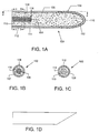
- Figs. 1A and 2A illustrate micro-needles 100 and 200, respectively, having a configuration that is substantially straight along the longitudinal axis and has a substantially circular cross-section.
- any suitable cross-sectional configuration may be employed including, but not limited to other annular shapes such as elliptical or oblong, or polygonal configurations, such as square and rectangular.
- the outer diameter of a micro-needle at its thickest point is between about 200 ⁇ m to 300 ⁇ m, and typically does not exceed about 350 ⁇ m. In certain embodiments the outer diameter is typically about 250 ⁇ m.
- An important aspect of the present invention is to eliminate or at least greatly minimize the pain and bleeding suffered by a patient during the sampling process. Accordingly, the penetration lengths and diameters of the micro-needles must be within certain ranges to accomplish this goal. Of course, those values will vary depending on the type of biological fluid (e . g ., interstitial fluid, blood or both) desired for sampling and the thickness of the skin layers of the particular patient being tested.
- biological fluid e . g ., interstitial fluid, blood or both
- the skin includes three distinct layers, a top layer called the epidermis, a middle layer called the dermis and a bottom layer called the subcutaneous layer.
- the epidermis is about 60 to 120 ⁇ m (microns) thick and comprises four distinct layers: a 10 to 20 ⁇ m outer layer, called the stratum corneum, followed by the stratum granulosum, stratum malpighii and stratum germinativum.
- the stratum corneum contains cells filled with bundles of cross-linked keratin and keratohyalin surrounded by an extracellular matrix of lipids.
- the inner three layers are collectively referred to as the viable epidermis and have a total thickness in the range of about 50 to 100 ⁇ m.
- the viable epidermis is responsible for diffusing metabolites to and from the dermis.
- the epidermis contains no blood cells or nerve endings.
- the dermis is much thicker than the epidermis, having a thickness in the range from about 2,000 to 3,000 ⁇ m.
- the dermal layer generally consists of a dense bed of connective tissue, including collagen fibers, and interstitial fluid dispersed throughout these fibers. Below the dermal layer is the subcutaneous tissue that contains the blood capillaries and the majority of nerve endings within the skin.
- the micro-needles of the present invention preferably have penetration lengths that extend no deeper than the dermis layer when fully penetrated into the skin in order to minimize pain, however, they may be longer if necessary for the particular sampling application at hand.
- the length-to-diameter aspect ratio of the micro-needle is another factor to consider in determining an optimal length for the subject micro-needles.
- the length of the micro-needle is generally at least about 5 times greater than the diameter of the micro-needle, but may be more or less.
- the minimum micro-needle diameter is dependent upon the necessary spacing between the electrodes and the diameters of the other components of the electrochemical cell.
- the subject micro-needles generally have a length in the range from about 500 to 4,000 ⁇ m, typically between about 600 to 3,000 ⁇ m, and more typically between about 1,000 to 2,000 ⁇ m; however, these lengths will vary from patient to patient depending on the thickness of the skin layers of the particular patient being tested. While the micro-needles may have lengths that are longer than the depth of the target skin layer, the micro-needle may be penetrated into the skin at depth (referred to as the penetration length) that is less than the length of the micro-needle structure. Thus, in order to minimize pain to the patient, the micro-needles preferably have a penetration length in the range from about 50 to 4,000 ⁇ m, and more typically from about 100 to 3,000 ⁇ m.
- the penetration length of the micro-needle is typically between about 50 to 120 ⁇ m.
- the penetration length of the micro-needle is typically from about 2,000 to 3,000 ⁇ m.
- Micro-needles 100 and 200 terminate at distal ends 104 and 204, respectively, in preferably sharp tips 102 and 202, respectively, having a beveled or sliced configuration, as shown in Fig. 1D, to more easily penetrate the skin.
- tips 102 and 202 may have other suitable configurations such as one that is not tapered and defines an edge that lies in a plane perpendicular to the longitudinal axis of the micro-needle (not shown).
- micro-needles in the form of an array, may be employed by the present invention.
- the number of micro-needles employed will depend upon various factors including the agent being detected, the body surface location into which the micro-needles are inserted, the sample site, the fluid volume and the like.
- the micro-needle array may comprise micro-needles having varying shapes, lengths, widths and tip configurations.
- the electrochemical cell of the present invention comprises an electrode arrangement of a working electrode and a reference electrode that provides an input reference signal to the sampled biological fluid constituent(s) and an output signal representing the concentration of the target constituent(s) or analyte(s) in the sampled fluid.
- the two electrodes are in a spaced-apart relationship such that a surface of one electrode faces a surface of the other electrode.
- the space between the two electrodes defines a reaction zone into which sampled constituent is transferred and is tested for the concentration of a targeted analyte.
- electrochemical systems and methods commonly known in the art of analyte detection and measurement may be employed by the present invention, including systems that are amperometric (i . e ., measure current), coulometric (i . e ., measure electrical charge) or potentiometric ( i . e ., measure voltage).
- amperometric i . e ., measure current
- coulometric i . e ., measure electrical charge
- potentiometric i . e ., measure voltage
- Figs. 1 and 2 illustrate two exemplary embodiments of the electrochemical cell of the present invention.
- Figs. 1A-C show an electrochemical cell embodiment having two co-axially aligned, concentrically-spaced electrodes fully housed within the micro-needle.
- Figs. 2A and B show an electrochemical cell embodiment having two substantially planar electrodes parallely-spaced at a proximal end of the micro-needle.
- micro-needle 100 includes an electrochemical cell that provides an electrical signal or signals representative of the concentration of the analyte being measured in a sampled biological fluid constituent.
- the electrochemical cell comprises various components or layers arranged concentrically with respect to each other. More specifically, this concentric arrangement may also be described as circumferential or co-axial.
- micro-needle 100 includes, a solid wire core 106 and an outer plating 114.
- the solid wire core 106 provides rigidity to the micro-needle structure and may be part of the adjacent electrode.
- the outer plating 114 may be made of stainless steel or the like.
- the subject electrochemical cell which includes a first or inner electrode 108, a second or outer electrode 112 and a reaction zone 110 therebetween. Second electrode 112 and outer plating 114 extend to define edge 116 and tip 102 of micro-needle 100.
- first or inner electrode 108 is shown covering the proximal end of solid wire core 106; however, the proximal end may be exposed.
- First electrode 108 and solid wire core 106 extend evenly to a point 118 (proximal to distal end 104) wherein these two layers have distal edges that are flush with each other. These flush edges define the closed proximal end of a lumen portion 120 having a lumenal wall, defined by second electrode 112 and outer plating 114, which extends to a distal opening at distal edge 116, as viewed in Fig. 1A.
- micro-needle 100 defined by lumen 120 and reaction zone 110 is filled with a constituent transfer medium, here a hydrophilic gel material, as discussed above.
- a constituent transfer medium here a hydrophilic gel material, as discussed above.
- the gel acts to absorb and transfer constituents of biological fluid present at tip 102 into lumen 120 and then into reaction zone 110.
- the length of outer electrode 112 may be substantially same as the penetration depth of the micro-needle, and thus is generally not greater than about 4,000 ⁇ m or less depending on the desired length of penetration. More typically, the length of the outer electrode is between about 1,000 ⁇ m to 3,000 ⁇ m, and preferably about 2,000 ⁇ m.
- the inner electrode may have the same length as the outer electrode but is preferably shorter. The length of the inner electrode is generally about 20% shorter than the outer electrode and is generally not greater than about 3,200 ⁇ m or less, and is typically between about 800 to 2,400 ⁇ m, and is more typically about 1,600 ⁇ m.
- Solid wire core 106 has a diameter in the general range from about 80 to 100 ⁇ m, and typically does not exceed about 120 ⁇ m. In certain embodiments the diameter is typically about 90 ⁇ m.
- First electrode 108 has a cylindrical configuration (although other configurations are possible) having a thickness in the general range from about 70 to 200 Angstroms, and typically does not exceed about 300 Angstroms. Thus, as first electrode is formed around core 106, it has an outside diameter that is slightly greater than that of core 106.
- Second electrode 112 also has a cylindrical configuration (although other configurations are possible) having a thickness in the general range from about 70 to 200 Angstroms, and typically does not exceed about 300 Angstroms.
- the reaction zone or spacing between the two electrodes also has a cylindrical configuration (although other configurations are possible) having a thickness in the general range from about 50 to 80 ⁇ m, and typically does not exceed about 200 ⁇ m.
- the thin outer tube 114 upon which the second electrode 112 is electroplated has a thickness in the general range from about 12 to 20 ⁇ m, and typically does not exceed 25 ⁇ m. Therefore, the total outside diameter of micro-needle 100 is generally no less than about 200 ⁇ m, and typically in the range from about 250 to 300 ⁇ m, and typically does not exceed about 350 ⁇ m.
- Lumen 120 has a volume generally in the range from about 20 to 140 nL, and typically does not exceed about 250 nL.
- micro-needle 200 having a tubular configuration defined by outer plating 214 and lumen 220.
- Lumen 220 has a volume generally in the range from about 25 to_280 nL, and more typically in the range from about 25 to 160 nL.
- the entirety of its length is hollow.
- Micro-needle 200 may have the same or similar length and diameter dimensions as discussed above, but may instead have smaller dimensions as the electrochemical cell is located outside micro-needle lumen 220 rather than housed within it.
- Electrode 208 defines a surface which circumferentially extends from proximal end 205 of micro-needle 200.
- electrode 208 is in the form of an annular ring, as shown in Fig. 2B but may have any suitable shape, such as square or rectangular.
- Electrode 212 is spaced proximally from electrode 208, defining a spacing there between which functions as the reaction zone 210 of the electrochemical cell.
- Electrode 212 preferably has a shape and size that correspond to the shape and size of electrode 208.
- electrode 212 preferably has a circular disk shape and a diameter the same as the outer diameter of electrode 208. This diameter dimension is generally in the range from about 600 to 800 ⁇ m, and typically does not exceed 1mm.
- the inner diameter of electrode 108 preferably matches the diameter of outer plating 214, and thus has values mentioned above.
- At least the surfaces of the electrodes of Figs. 1 and 2 that face the reaction zones 110 and 210 within micro-needles 100 and 200, respectively, are comprised of highly conductive metal, such as palladium, gold, platinum, silver, iridium, carbon, doped indium tin oxide, stainless steel and the like, or a combination of such materials. Most typically the metal is gold, platinum or palladium.
- each electrode can be made up of an inert support or backing substrate on the surface of which is a thin layer of the metal component ( e . g ., an electroplated metal layer) of the electrode.
- the constituent transfer medium of the sampling means of the present invention may occupy the entire volume of the reaction zones 110 and 210, respectively, and at least a portion of each micro-needle needle lumen 120 and 220, respectively, but may completely fill the lumen.
- the constituent transfer medium is preferably made of a water-based gel material or matrix having a high affinity for water, i . e ., is highly water-absorbent.
- the hydrophilic gel helps to precondition the electrodes and reconstitute the reagent material in preparation for the electrochemical measurement of target analytes.
- the transfer medium's ability to absorb fluids, particularly water, is dependent upon the extent to which the transfer medium is saturated prior to being exposed to fluid.
- the constituent transfer medium is preferably provided in a fully saturated state prior to insertion of the micro-needle into the skin.
- interstitial fluid for example, is about 98% water, the reduction in diffusion time through the gel may be significant in certain applications.
- the speed at which they reach the reaction zone will vary depending on the size of the molecules of the constituents. Generally, the smaller the molecule the faster the diffusion rate through the gel. As many commonly targeted analytes, such as glucose, electrolytes, ascorbic acid, uric acid, etc., have small molecules, these analytes will diffuse through the gel matrix faster than other components of the interstitial fluid comprised of larger molecules.
- the concentration kinetics of the selected hydrogel is that of a first order system. As such, the constituent transfer rate and the analyte concentration level of the biological fluid are more predictable.
- the value of the time constant depends on several factors: (1) the area of the interface between the hydrogel and the interstitial fluid ( i . e ., the surface area of the opening defined by edge 116 and 216 of micro-needles 100 and 200, respectively, (2) the volume of the hydrogel, and (3) the transport characteristics of the target analyte through the particular hydrogel material used.
- the graph of Fig. 3 depicts the first order system described in the above equation.
- the dependent axis represents time (t) where t o is the point in time at which a micro-needle is inserted into the skin.
- t o is the point in time at which a micro-needle is inserted into the skin.
- the time it takes for the constituent concentration in the hydrogel to reach equilibrium with that of the biological fluid present at the distal opening of the micro-needle is generally no more than about 5 times the time constant of the system. If the time to achieve equilibrium is impractical for a given application, the micro-needle may be removed from the skin prior to reaching equilibrium and then the analyte concentration level within the patient (C o ) can be calculated based on the first order characteristics of the system. Alternately, the time duration of contact between the micro-needle and the interstitial fluid may be controlled ( i.e., fixed) and C o can be derived based on the first order equation above.
- Gel materials suitable for use as the constituent transfer medium of the present invention include natural gels made up of naturally occurring polymers, such as agarose, gelatin, mucopolysaccharide, starch and the like, and synthetic gels made up, at least in part, of synthetic polymers, such as anyone of the neutral water-soluble polymers or polyelectrolytes ( i . e ., synthetic or natural polymers which form ionic charges when dissolved in water), such as polyvinyl pyrrolidone, polyethylene glycol, polyacrylic acid, polyvinyl alcohol, polyacrylamide, and copolymers thereof.
- synthetic polymers such as anyone of the neutral water-soluble polymers or polyelectrolytes ( i . e ., synthetic or natural polymers which form ionic charges when dissolved in water), such as polyvinyl pyrrolidone, polyethylene glycol, polyacrylic acid, polyvinyl alcohol, polyacrylamide, and copolymers thereof.
- a redox reagent is typically employed within the reaction zone within the electrochemical cell.
- the redox reagent material is typically deposited on at least one of the facing surfaces of the two electrodes whereby biological fluid present in the reaction zone chemically reacts with the reagent material.
- the reagent is preferably coated or deposited on the surface(s) by means of dip coating.
- the reagent being used is selected based on the analyte targeted for detection.
- the interaction of the reagent system and the corresponding constituent or analyte is employed in the electrochemical measurement protocol to determine the concentration of the target analyte or constituent in the cell.
- the reagent system present in the reaction area typically includes at least an enzyme(s) and a mediator.
- the enzyme member(s) of the reagent system is an enzyme or a plurality of enzymes that work in concert to oxidize the analyte of interest.
- the enzyme component of the reagent system is made up of a single analyte oxidizing enzyme or a collection of two or more enzymes that work in concert to oxidize the analyte of interest.
- Enzymes of interest include oxidases, dehydrogenases, lipases, kinases, diaphorases, quinoproteins and the like.
- the specific enzyme present in the reaction area depends on the particular analyte for which the electrochemical test strip is designed to detect, where representative enzymes include: glucose oxidase, glucose dehydrogenase, cholesterol esterase, cholesterol oxidase, lipoprotein lipase, glycerol kinase, glycerol-3-phosphate oxidase, lactate oxidase, lactate dehydrogenase, pyruvate oxidase, alcohol oxidase, bilirubin oxidase, uricase, and the like.
- the enzyme component of the reagent system is a glucose-oxidizing enzyme (e.g., a glucose oxidase or glucose dehydrogenase).
- the second component of the reagent system is a mediator component, which is made up of one or more mediator agents.
- mediator agents include: ferricyanide, phenazine ethosulphate, phenazine methosulfate, pheylenediamine, 1-methoxy-phenazine methosulfate, 2,6-dimethyl-1,4-benzoquinone, 2,5-dichloro-1,4-benzoquinone, ferrocene derivatives, osmium bipyridyl complexes, ruthenium complexes and the like.
- the mediator of particular interest is ferricyanide.
- buffering agents e . g ., citraconate, citrate, phosphate
- Good buffers and the like.
- the reagent is generally present in dry form.
- the amounts of the various components may vary wherein the amount of enzyme component typically ranges from about 0.1 to 10% by weight.
- the reference and working electrodes of the electrochemical cell are in electrical communication with a control means that sets the input reference signal transmitted to the electrochemical cell, receives the output signal from the electrochemical cell and then derives the concentration level of the analyte within the sample from the output signal.
- the control means provides a means for applying an electrical current between the two electrodes, measuring a change in the current over time and relating the observed change in current to the concentration of analyte present in the electrochemical cell.
- the concentration of the analyte in the patient's blood is then derived, the numerical value of which is preferably provided as an output signal to a display means.
- control and display means are integrally housed within a hand-held control unit such as that illustrated in Fig. 4.
- the control unit preferably also provides a means of securing or holding one or more micro-needles or an array of micro-needles in a position and arrangement suitable for the particular sampling and measuring application at hand.
- Sensor system 50 comprises a hand-held control unit 52 and a sensor device 10 operatively mounted to distal end 54 of control unit 52.
- Sensor device 10 includes array of the micro-needles of the present invention, such as micro-needle 100 of Figs. 1 and 2.
- Control unit 52 has a housing 56, preferably made of a medical grade plastic material, having a low-profile configuration which houses a means (not shown) for controlling the measurement means of sensor device 10, i.e., generating and transmitting input reference signals to the electrochemical cell of micro-needle 100 and receiving output measurement signals from the cell.
- a software algorithm programmed within control unit 52 automatically calculates and determines the concentration of the target analyte in the biological sample upon receipt of the output signal.
- the concentration level (among other desired information) is then transmitted to an external display means or screen 58 that displays information to the user.
- Control interface buttons 60 are provided to allow the user to input information, such as the type of analyte targeted for measurement, to the control means.
- Sensor device 10 is electrically and physically coupled to control unit 52. Electrical communication between the two is established by means of conductive contacts (not shown) on device 10 and corresponding electrical traces (not shown) within control unit 52. Preferably, device 10 and control unit 52 are physically coupled by a quick lock-and-release mechanism (many of which are commonly known) such that a used sensor device can be easily removed and replaced. Control unit 52 is preferably reusable and usable with any number of sensor devices of the subject invention. These features facilitate the taking of multiple samples and measurements in an efficient and rapid manner.
- Also provided by the subject invention are methods for using the subject devices and sensor systems to determine the concentration of an analyte in a physiological sample.
- a variety of different analytes may be detected using the subject sensor systems, where representative analytes include glucose, cholesterol, lactate, alcohol, and the like.
- the first step is to provide a sensor device 10 having one or more micro-needles 100 of the present invention.
- sensor device 10 is particularly configured ( i . e ., containing the appropriate reagent) for targeting the analyte(s) of interest.
- the sensor device 10 is operatively engaged and interfaced with a control unit 52 that can be manually held and controlled by the user.
- Control unit 52 is programmed for testing the targeted analyte(s).
- the user positions sensor device 10 over a selected area of the patient's skin, and, with slight pressure, the array of micro-needles 100 of sensor device 10 are caused to penetrate into the skin.
- the depth to which the micro-needles 100 are inserted will depend on the length of the respective micro-needles or by some other means associated with the sensor unit 10 for limiting the insertion depth.
- an amount i . e ., a sample
- constituents of the biological fluid present at the open tips 102 of micro-needles 100 is absorbed by the gel-based, constituent transfer medium into lumens 120 of the respective micro-needles by means of osmosis.
- the targeted analyte(s) chemically reacts with the selected reagent(s) to form electroactive products.
- the electroactive products are then either oxidized or reduced by the optional mediator or directly by the working electrode 108.
- the resulting output signal level is then conducted to the control unit by electrode 108.
- a software algorithm programmed within control unit 52 then automatically determines the differential between the output and reference signals, derives the concentration of analyte in the sample from this differential value, and then derives the corresponding concentration level of the selected analyte(s) in the patient's blood. Any or all of these values may be displayed by display means or screen 58.
- a device such as control unit 52 which automatically calculates and determines the concentration of a selected analyte in a biological sample and/or in the patient's system, such that a user need only insert a micro-needle of the subject invention into the patient's skin and then read the final analyte concentration result from a display of the device, is further described in U.S. Patent No. 6,193,873 entitled “Sample Detection to Initiate Timing of an Electrochemical Assay," the disclosure of which is herein incorporated by reference.
- kits for use in practicing the subject methods include at least one subject sensor device having one or more micro-needles.
- the kits may also include a reusable or disposable control unit that may be used with reusable or disposable sensor devices of the kit or from other kits of the subject invention.
- These kits may include sensors having an array of micro-needles having the same or different lengths.
- Certain kits may include various sensors each containing the same or different reagents.
- kits preferably include instructions for using the subject sensors in the determination of an analyte concentration in a physiological sample. These instructions may be present on one or more of the packaging, a label insert, or containers present in the kits, and the like.
- the subject inventions are easy to use and can provide for analyte testing without the need to cut or lance the skin and without minimal or no pain and blood. As such, the subject invention represents a significant contribution to the field.
Abstract


Description
- This invention is related to percutaneous biological fluid sampling and analyte measurement, and more particularly to constituent transfer mediums to facilitate sampling of biological fluid.
- The detection of analytes in biological fluids is of ever increasing importance. Analyte detection assays find use in a variety of applications, including clinical laboratory testing, home testing, etc., where the results of such testing play a prominent role in the diagnosis and management of a variety of disease conditions. Common analytes of interest include glucose, e.g., for diabetes management, cholesterol, and the like.
- A common technique for collecting a sample of blood for analyte determination is to pierce the skin at least into the subcutaneous layer to access the underlining blood vessels in order to produce localized bleeding on the body surface. The accessed blood is then collected into a small tube for delivery and analyzed by testing equipment, often in the form of a hand-held instrument having a reagent test strip onto which the blood sample is placed. The fingertip is the most frequently used site for this method of blood collection due to the large number of small blood vessels located therein. This method has the significant disadvantage of being very painful because subcutaneous tissue of the fingertip has a large concentration of nerve endings. It is not uncommon for patients who require frequent monitoring of an analyte to avoid having their blood sampled. With diabetics, for example, the failure to frequently measure their glucose level on a prescribed basis results in a lack of information necessary to properly control the level of glucose. Uncontrolled glucose levels can be very dangerous and even life-threatening. This technique of blood sampling also runs the risk of infection and the transmission of disease to the patient, particularly when done on a high-frequency basis. The problems with this technique are exacerbated by the fact that there is a limited amount of skin surface that can be used for the frequent sampling of blood.
- To overcome the disadvantages of the above technique and others that are associated with a high degree of pain, certain analyte detection protocols and devices have been developed that use micro-needles or analogous structures to access the interstitial fluid within the skin. The micro-needles are penetrated into the skin to a depth less than the subcutaneous layer so as to minimize the pain felt by the patient. The interstitial fluid is then sampled and tested to determine the concentration of the target constituent. The concentration of a constituent within the interstitial fluid is representative of the concentration of that constituent in other bodily fluids, such as blood.
- Conventional micro-needle sampling systems have a drawback in that, because the interstitial fluid inside the human body is at a negative pressure of about 6 mm/Hg, some kind of mechanical or vacuum means is often used in conjunction with the micro-piercing members.
- For example, International Patent Application WO 99/27852 discloses the use of vacuum pressure and/or heat to increase the availability of interstitial fluid at the area of skin in which the vacuum or heat is applied. The vacuum pressure causes the portion of skin in the vicinity of the vacuum to become stretched and engorged with interstitial fluid, facilitating the extraction of fluid upon entry into the skin. Another method is disclosed wherein a localized heating element is positioned above the skin, causing interstitial fluid to flow more rapidly at that location, thereby allowing more interstitial fluid to be collected per given unit to time.
- Still other detection devices have been developed which avoid penetration of the skin altogether. Instead the outermost layer of skin, called the stratum corneum, is "disrupted" by a more passive means to provide access to or extraction of biological fluid within the skin. Such means includes the use of oscillation energy, the application of chemical reagents to the skin surface, etc. For example, International Patent Application WO 98/34541 discloses the use of an oscillation concentrator, such as a needle or wire, which is positioned at a distance from the skin surface and caused to vibrate by means of an electro-mechanical transducer. The needle is immersed in a receptacle containing a liquid medium placed in contact with the skin. The mechanical vibration of the needle is transferred to the liquid, creating hydrodynamic stress on the skin surface sufficient to disrupt the cellular structure of the stratum corneum. International Patent Applications WO 97/42888 and WO 98/00193 also disclose methods of interstitial fluid detection using ultrasonic vibration.
- Thus, despite the work that has already been done in the area of analyte testing, there is a continued interest in the identification of new analyte detection methods that more readily meet the needs of the relevant market. Of particular interest would be the development of a minimally invasive analyte detection system that is practical, manufacturable, accurate and easy to use, as well as safe and efficacious.
- U.S. Patents of interest include: 5,582,184, 5,746,217, 5,820,570, 5,942,102, 6,091,975 and 6,162,611. Other patent documents and publications of interest include: WO 97/00441, WO 97/42888, WO 98/00193 WO 98/34541, WO 99/13336, WO 99/27852, WO 99/64580, WO 00/35530, WO 00/57177 and WO 00/74765A1.
- Percutaneous biological fluid sampling and analyte measurement systems and devices, as well as methods for using the same are provided by the subject invention. A feature of the subject devices is the presence of a constituent transfer medium that samples and transfers at least the target constituent(s) of biological fluid accessed within the skin to an electrochemical cell for measurement of the targeted constituent(s) within the fluid sample. The present invention finds use in accessing biological fluids such as blood and interstitial fluid, and in the detection and measurement of various analytes, e.g., glucose, cholesterol, electrolytes, pharmaceuticals, or illicit drugs, and the like, which are present in the accessed biological fluid. The present invention is especially well-suited for the sampling and measurement of interstitial fluid constituents such as glucose.
- In general, the subject sampling and measurement devices include an elongated skin-piercing or skin-penetrating means to provide access to the biological fluid, at least one sampling means in the form of a constituent transfer medium, and a measuring means in the form of an electrochemical measurement cell in fluid communication with the constituent transfer medium.
- The skin-penetrating means includes at least one micro-needle defining a substantially annular bore or channel through at least a portion of the interior of the micro-needle structure and having an access opening at a distal end through which one or more biological fluid constituents enter into the device. In many embodiments, the skin-piercing means comprises an array of such micro-needles.
- The electrochemical measurement cell comprises spaced-apart working and reference electrodes positioned within and/or further defining the micro-needle structure. The area between the electrodes is defined as the reaction zone in which the actual measurement of analyte concentration takes place. In certain embodiments, the electrode pair are co-axially positioned and concentrically-spaced from each other, wherein at least the outer electrode has a hollow, cylindrical configuration and, at least in part, defines the micro-needle structure. The inner electrode is positioned within the cylindrical wall of the outer electrode and may also have a cylindrical configuration, either as hollow cylinder filled with a center core material or as a solid cylinder. In other embodiments, the electrochemical cell defines the proximal end of the micro-needle structure in the form of two parallel-spaced planes positioned substantially transverse to the longitudinal axis of the micro-needle.
- In operation, one of the electrodes of the electrochemical cell is used as the reference electrode by which an input reference signal is provided to the sensor from a signal generating means. The other electrode operates as a working electrode that provides an output signal from the sensor to a signal receiving means. Preferably, the reference electrode is located at the bottom and the working electrode is located at the top of the device. This output signal represents the concentration of the target analyte in accessed biological fluid.
- A redox reagent system or material may be used within the electrochemical cell to facilitate targeting the analyte(s) of interest. The particular redox reagent material used is selected based on the analyte targeted for measurement.
- The constituent transfer medium of the sampling means occupies the area between the two electrodes, referred to as the reaction zone, and at least a portion of each micro-needle channel. The constituent transfer medium is made of a hydrogel or gel material or matrix that is hydrophilic and has an affinity for ionic and anionic particles within biological fluid. Optionally, the gel matrix may be configured to transfer only particles having a molecular weight less than a specified weight. The gel acts to transfer at least the targeted biological fluid constituent(s) present at the access opening of a micro-needle into the reaction zone. In other words, the targeted constituent(s) migrates through the gel matrix until equilibrium is reached between the concentration of the constituent(s)within the tissue and the concentration of the constituent(s) within the gel matrix. As compared to a hollow micro-needle which relies solely on capillary force that it exerts on the biological fluid as a means to transfer the biological fluid to the electrochemical cell, the subject constituent transfer medium may be configured (i.e., presented in a fully saturated state) to eliminate the transfer of water and other fluids contained within the accessed biological fluid, while transferring only constituents of the biological fluid. It is the configuration of the electrochemical cell that selects the targeted constituent(s) from the remaining constituents for testing.
- The gel matrix of the present invention is characterized by a concentration gradient that changes in accordance with a first order system. This allows calculation of ionic and non-ionic element concentrations by means of the exponential characteristics of the first order system.
- The subject sensor devices may function as a part of an analyte sensing system that includes a means for controlling the sensor device. Specifically, a control unit is provided in which the control means is electrically coupled with the sensor device and functions to generate and send input signals to the electrochemical cell and to receive output signals from the cell. These functions, among others, are performed by a software algorithm programmed within the control unit that automatically calculates and determines the concentration of the target analyte in the biological sample upon receipt of an output signal from the electrochemical cell.
- An exemplary method of the subject invention involves using at least one subject sensor device comprising one or more hollow micro-needles having an open distal end defining a constituent transfer pathway to an integrally-coupled electrochemical cell. A hydrophilic gel material fills the interior of the micro-needle and the electrochemical cell. The micro-needle is inserted into the skin to a selected depth, preferably to a depth that avoids contacting nerve endings and blood vessels. Next, the at least the targeted constituent(s) of the biological fluid present at the open distal end of the micro-needle is wicked into the gel material and transferred into the reaction zone of the electrochemical cell. An electrochemical measurement is then made between the working and reference electrodes that provides an electrical signal that is representative of the concentration the constituent in the sample. The concentration of the constituent in the patient's blood is then derived from the obtained electrical signal. A numerical value representing this concentration may then be displayed on a display unit. A software algorithm that is part of the device, e.g., programmed into a control unit present in the device, may be employed to determine the signal levels transmitted by the control unit to the cell and for deriving the concentration level of the target analyte.
- The subject devices, systems and methods find use in analyte concentration measurement of a variety of analytes and are particularly suited for use in the measurement of glucose concentration in interstitial fluid.
-
- Figure 1 includes Figures 1A, 1B, 1C and 1D wherein Fig. 1A is a cut-away view of a length of an embodiment of the micro-needle of the present invention, Fig. 1B is a cross-sectional view of the micro-needle of Fig. 1A along the arrows b-b, Fig. 1C is a cross-sectional view of the micro-needle of Fig. 1A along the arrows c-c and Fig. 1D is a top view of the micro-needle of Fig. 1A along the arrows d-d;
- Figure 2 includes Figures 2A and 2B wherein Fig. 2A is a cut-away view of a length of another embodiment of the micro-needle of the present invention and Fig. 2B is a cross-sectional view of the micro-needle of Fig. 2A taken along the arrows b-b;
- Figure 3 is a graphical representation of the first order system of the gel matrix of the present invention; and
- Figure 4 is a schematic representation of the sampling and measurement device of the present invention.
-
- Percutaneous biological fluid, e.g., interstitial fluid, sampling and analyte measurement sensor devices and systems, as well as methods for using the same, are provided. The present invention finds use in the sampling of constituents found in biological fluids such as blood and interstitial fluid, and in the detection and measurement of a variety of different analytes, e.g., glucose, cholesterol, electrolytes, pharmaceuticals, illicit drugs, and the like.
- In general, the subject devices include a skin-piercing means, a biological fluid constituent sampling means in the form of a constituent transfer medium, and a constituent concentration measuring means in the form of an electrochemical cell in fluid communication with the constituent transfer medium. Preferably these components are integrated into a single structure.
- Before the subject invention is described further, it is to be understood that the invention is not limited to the particular embodiments of the invention described below, as variations of the particular embodiments may be made and still fall within the scope of the appended claims. It is also to be understood that the terminology employed is for the purpose of describing particular embodiments, and is not intended to be limiting. Instead, the scope of the present invention will be established by the appended claims.
- Where a range of values is provided, it is understood that each intervening value, to the tenth of the unit of the lower limit unless the context clearly dictates otherwise, between the upper and lower limit of that range and any other stated or intervening value in that stated range is encompassed within the invention. The upper and lower limits of these smaller ranges may independently be included in the smaller ranges is also encompassed within the invention, subject to any specifically excluded limit in the stated range. Where the stated range includes one or both of the limits, ranges excluding either both of those included limits are also included in the invention.
- Unless defined otherwise, all technical and scientific terms used herein have the same meaning as commonly understood by one of ordinary skill in the art to which this invention belongs. Although any methods and materials similar or equivalent to those described herein can also be used in the practice or testing of the present invention, the preferred methods and materials are now described. All publications mentioned herein are incorporated herein by reference to disclose and describe the methods and/or materials in connection with which the publications are cited.
- It must be noted that as used herein and in the appended claims, the singular forms "a", "an", and "the" include plural referents unless the context clearly dictates otherwise. Thus, for example, reference to "a test strip" includes a plurality of such test strips and reference to "the processor" includes reference to one or more processors and equivalents thereof known to those skilled in the art, and so forth.
- The publications discussed herein are provided solely for their disclosure prior to the filing date of the present application. Nothing herein is to be construed as an admission that the present invention is not entitled to antedate such publication by virtue of prior invention. Further, the dates of publication provided may differ from the actual publication dates which may need to be independently confirmed.
- The skin-penetration means comprises at least one micro-piercing member, preferably in the form of a micro-needle, used to penetrate the skin to a depth where pain and bleeding are minimized, and preferably non-existent. Thus, it is preferable that the micro-needle penetrates above the level where nerves are present. As such, target skin layers into which the subject piercing members may extend include the dermis, epidermis and the stratum corneum (i.e., the outermost layer of the epidermis).
- The micro-needle defines a substantially annular bore or channel through the interior of a narrow, elongated structure having a distal access opening through which biological fluid constituents may enter into the micro-needle. In certain embodiments of the sensor devices of the present invention, the skin-piercing means comprises an array of such micro-needles.
- The subject micro-needles are configured to be mechanically stable and strong enough to penetrate the stratum corneum without breaking or flexing. Preferably, they are made of a biocompatible material so as not to cause irritation to the skin or an undesirable tissue response. Although the sensor devices may be disposable, for reusable embodiments, it is preferable that the material of the micro-needles and/or micro-needle arrays is able to withstand sterilization cycles.
- The micro-needles and/or the array of micro-needles may be formed of or coated with an insulating material, such as a ceramic, glass, silica, polymer, plastics and the like. Examples of polymers are polyacrylates, epoxies, polyesters polyetheretherketone, liquid crystalline polyesters, or their composites. Examples of ceramics are aluminum oxide, silicon carbide and zirconium oxide. Suitable metallic materials include stainless steel, titanium, precious metals or alloys thereof and the like.
- The general configuration of exemplary micro-needles of the present invention will now be described with reference to Figs. 1 and 2. Figs. 1A and 2A illustrate micro-needles 100 and 200, respectively, having a configuration that is substantially straight along the longitudinal axis and has a substantially circular cross-section. However, any suitable cross-sectional configuration may be employed including, but not limited to other annular shapes such as elliptical or oblong, or polygonal configurations, such as square and rectangular. The outer diameter of a micro-needle at its thickest point is between about 200 µm to 300 µm, and typically does not exceed about 350 µm. In certain embodiments the outer diameter is typically about 250 µm.
- An important aspect of the present invention is to eliminate or at least greatly minimize the pain and bleeding suffered by a patient during the sampling process. Accordingly, the penetration lengths and diameters of the micro-needles must be within certain ranges to accomplish this goal. Of course, those values will vary depending on the type of biological fluid (e.g., interstitial fluid, blood or both) desired for sampling and the thickness of the skin layers of the particular patient being tested.
- The skin includes three distinct layers, a top layer called the epidermis, a middle layer called the dermis and a bottom layer called the subcutaneous layer. The epidermis is about 60 to 120 µm (microns) thick and comprises four distinct layers: a 10 to 20 µm outer layer, called the stratum corneum, followed by the stratum granulosum, stratum malpighii and stratum germinativum. The stratum corneum contains cells filled with bundles of cross-linked keratin and keratohyalin surrounded by an extracellular matrix of lipids. The inner three layers are collectively referred to as the viable epidermis and have a total thickness in the range of about 50 to 100 µm. The viable epidermis is responsible for diffusing metabolites to and from the dermis. The epidermis contains no blood cells or nerve endings. The dermis is much thicker than the epidermis, having a thickness in the range from about 2,000 to 3,000 µm. The dermal layer generally consists of a dense bed of connective tissue, including collagen fibers, and interstitial fluid dispersed throughout these fibers. Below the dermal layer is the subcutaneous tissue that contains the blood capillaries and the majority of nerve endings within the skin.
- Thus, the micro-needles of the present invention preferably have penetration lengths that extend no deeper than the dermis layer when fully penetrated into the skin in order to minimize pain, however, they may be longer if necessary for the particular sampling application at hand. The length-to-diameter aspect ratio of the micro-needle is another factor to consider in determining an optimal length for the subject micro-needles. In order to effectively and atraumatically penetrate the skin, the length of the micro-needle is generally at least about 5 times greater than the diameter of the micro-needle, but may be more or less. The minimum micro-needle diameter is dependent upon the necessary spacing between the electrodes and the diameters of the other components of the electrochemical cell.
- Thus, the subject micro-needles generally have a length in the range from about 500 to 4,000 µm, typically between about 600 to 3,000 µm, and more typically between about 1,000 to 2,000 µm; however, these lengths will vary from patient to patient depending on the thickness of the skin layers of the particular patient being tested. While the micro-needles may have lengths that are longer than the depth of the target skin layer, the micro-needle may be penetrated into the skin at depth (referred to as the penetration length) that is less than the length of the micro-needle structure. Thus, in order to minimize pain to the patient, the micro-needles preferably have a penetration length in the range from about 50 to 4,000 µm, and more typically from about 100 to 3,000 µm. For example, for sampling applications that require penetration only into the epidermis layer, the penetration length of the micro-needle is typically between about 50 to 120 µm. For sampling applications which require penetration into but no deeper than the dermis layer, the penetration length of the micro-needle is typically from about 2,000 to 3,000 µm.
-
Micro-needles distal ends 104 and 204, respectively, in preferablysharp tips tips - Any suitable number of micro-needles, in the form of an array, may be employed by the present invention. The number of micro-needles employed will depend upon various factors including the agent being detected, the body surface location into which the micro-needles are inserted, the sample site, the fluid volume and the like. The micro-needle array may comprise micro-needles having varying shapes, lengths, widths and tip configurations.
- The electrochemical cell of the present invention comprises an electrode arrangement of a working electrode and a reference electrode that provides an input reference signal to the sampled biological fluid constituent(s) and an output signal representing the concentration of the target constituent(s) or analyte(s) in the sampled fluid. The two electrodes are in a spaced-apart relationship such that a surface of one electrode faces a surface of the other electrode. The space between the two electrodes defines a reaction zone into which sampled constituent is transferred and is tested for the concentration of a targeted analyte.
- Various types of electrochemical systems and methods commonly known in the art of analyte detection and measurement may be employed by the present invention, including systems that are amperometric (i.e., measure current), coulometric (i.e., measure electrical charge) or potentiometric (i.e., measure voltage). Examples of these types of electrochemical measurement systems are further described in U.S. Patent Nos.: 4,224,125; 4,545,382; and 5,266,179; as well as WO 97/18465 and WO 99/49307; the disclosures of which are herein incorporated by reference.
- Figs. 1 and 2 illustrate two exemplary embodiments of the electrochemical cell of the present invention. In particular, Figs. 1A-C show an electrochemical cell embodiment having two co-axially aligned, concentrically-spaced electrodes fully housed within the micro-needle. Figs. 2A and B show an electrochemical cell embodiment having two substantially planar electrodes parallely-spaced at a proximal end of the micro-needle.
- Turning now to the embodiment of Figs. 1A-C, micro-needle 100 includes an electrochemical cell that provides an electrical signal or signals representative of the concentration of the analyte being measured in a sampled biological fluid constituent. The electrochemical cell comprises various components or layers arranged concentrically with respect to each other. More specifically, this concentric arrangement may also be described as circumferential or co-axial.
- Viewed longitudinally in Fig. 1A and in cross-section in Fig. 1B, micro-needle 100 includes, a
solid wire core 106 and anouter plating 114. Thesolid wire core 106 provides rigidity to the micro-needle structure and may be part of the adjacent electrode. Theouter plating 114 may be made of stainless steel or the like. Betweenwire core 106 andouter plating 114 resides the subject electrochemical cell, which includes a first orinner electrode 108, a second orouter electrode 112 and areaction zone 110 therebetween.Second electrode 112 andouter plating 114 extend to defineedge 116 and tip 102 ofmicro-needle 100. - As shown in the proximal end view of Fig. 1C taken along arrows c-c of Fig. 1A, first or
inner electrode 108 is shown covering the proximal end ofsolid wire core 106; however, the proximal end may be exposed.First electrode 108 andsolid wire core 106, extend evenly to a point 118 (proximal to distal end 104) wherein these two layers have distal edges that are flush with each other. These flush edges define the closed proximal end of alumen portion 120 having a lumenal wall, defined bysecond electrode 112 andouter plating 114, which extends to a distal opening atdistal edge 116, as viewed in Fig. 1A. - The open or hollow space within micro-needle 100 defined by
lumen 120 andreaction zone 110 is filled with a constituent transfer medium, here a hydrophilic gel material, as discussed above. The gel acts to absorb and transfer constituents of biological fluid present attip 102 intolumen 120 and then intoreaction zone 110. - Suitable dimensions for the various components of the electrochemical cell of Fig. 1 are as follows. Typically, the length of
outer electrode 112 may be substantially same as the penetration depth of the micro-needle, and thus is generally not greater than about 4,000 µm or less depending on the desired length of penetration. More typically, the length of the outer electrode is between about 1,000 µm to 3,000 µm, and preferably about 2,000 µm. The inner electrode may have the same length as the outer electrode but is preferably shorter. The length of the inner electrode is generally about 20% shorter than the outer electrode and is generally not greater than about 3,200 µm or less, and is typically between about 800 to 2,400 µm, and is more typically about 1,600 µm. -
Solid wire core 106 has a diameter in the general range from about 80 to 100 µm, and typically does not exceed about 120 µm. In certain embodiments the diameter is typically about 90 µm.First electrode 108 has a cylindrical configuration (although other configurations are possible) having a thickness in the general range from about 70 to 200 Angstroms, and typically does not exceed about 300 Angstroms. Thus, as first electrode is formed aroundcore 106, it has an outside diameter that is slightly greater than that ofcore 106.Second electrode 112 also has a cylindrical configuration (although other configurations are possible) having a thickness in the general range from about 70 to 200 Angstroms, and typically does not exceed about 300 Angstroms. The reaction zone or spacing between the two electrodes also has a cylindrical configuration (although other configurations are possible) having a thickness in the general range from about 50 to 80 µm, and typically does not exceed about 200 µm. The thinouter tube 114 upon which thesecond electrode 112 is electroplated has a thickness in the general range from about 12 to 20 µm, and typically does not exceed 25 µm. Therefore, the total outside diameter of micro-needle 100 is generally no less than about 200 µm, and typically in the range from about 250 to 300 µm, and typically does not exceed about 350 µm.Lumen 120 has a volume generally in the range from about 20 to 140 nL, and typically does not exceed about 250 nL. - Referring now to the embodiment of Figs. 2A and B, there is shown a micro-needle 200 having a tubular configuration defined by
outer plating 214 andlumen 220.Lumen 220 has a volume generally in the range from about 25 to_280 nL, and more typically in the range from about 25 to 160 nL. Unlikemicro-needle 100 of Fig. 1, the entirety of its length is hollow.Micro-needle 200 may have the same or similar length and diameter dimensions as discussed above, but may instead have smaller dimensions as the electrochemical cell is located outsidemicro-needle lumen 220 rather than housed within it. - An electrochemical cell, defined by parallel,
planar electrodes proximal end 205 ofmicro-needle 200. As such, the electrochemical cell remains outside the skin surface upon insertion of micro-needle into the skin of a patient.Electrode 208 defines a surface which circumferentially extends fromproximal end 205 ofmicro-needle 200. Here,electrode 208 is in the form of an annular ring, as shown in Fig. 2B but may have any suitable shape, such as square or rectangular.Electrode 212 is spaced proximally fromelectrode 208, defining a spacing there between which functions as thereaction zone 210 of the electrochemical cell. This spacing is generally in the range from about 50 to 80 µm, and typically does not exceed 150 µm.Electrode 212 preferably has a shape and size that correspond to the shape and size ofelectrode 208. Here,electrode 212 preferably has a circular disk shape and a diameter the same as the outer diameter ofelectrode 208. This diameter dimension is generally in the range from about 600 to 800 µm, and typically does not exceed 1mm.. The inner diameter ofelectrode 108 preferably matches the diameter ofouter plating 214, and thus has values mentioned above. - At least the surfaces of the electrodes of Figs. 1 and 2 that face the
reaction zones micro-needles - The constituent transfer medium of the sampling means of the present invention may occupy the entire volume of the
reaction zones micro-needle needle lumen - The transfer medium's ability to absorb fluids, particularly water, is dependent upon the extent to which the transfer medium is saturated prior to being exposed to fluid. In order to reduce the time for which the micro-needle is inserted or applied to the skin, the constituent transfer medium is preferably provided in a fully saturated state prior to insertion of the micro-needle into the skin. As such, only the non-fluid constituents, including the one or more targeted constituents, contained within the biological fluid are transferred, thereby eliminating time for the preliminary transfer of biological fluid. As interstitial fluid, for example, is about 98% water, the reduction in diffusion time through the gel may be significant in certain applications.
- As between the constituents which are able to diffuse into and through the gel matrix, the speed at which they reach the reaction zone will vary depending on the size of the molecules of the constituents. Generally, the smaller the molecule the faster the diffusion rate through the gel. As many commonly targeted analytes, such as glucose, electrolytes, ascorbic acid, uric acid, etc., have small molecules, these analytes will diffuse through the gel matrix faster than other components of the interstitial fluid comprised of larger molecules.
- The concentration kinetics of the selected hydrogel is that of a first order system. As such, the constituent transfer rate and the analyte concentration level of the biological fluid are more predictable. This first order system is represented by the following equation and the graph of Fig. 3:
edge micro-needles - The graph of Fig. 3 depicts the first order system described in the above equation. The dependent axis represents time (t) where to is the point in time at which a micro-needle is inserted into the skin. With hydrogel materials suitable for use with the present invention, the time it takes for the constituent concentration in the hydrogel to reach equilibrium with that of the biological fluid present at the distal opening of the micro-needle, is generally no more than about 5 times the time constant of the system. If the time to achieve equilibrium is impractical for a given application, the micro-needle may be removed from the skin prior to reaching equilibrium and then the analyte concentration level within the patient (Co) can be calculated based on the first order characteristics of the system. Alternately, the time duration of contact between the micro-needle and the interstitial fluid may be controlled (i.e., fixed) and Co can be derived based on the first order equation above.
- Gel materials suitable for use as the constituent transfer medium of the present invention include natural gels made up of naturally occurring polymers, such as agarose, gelatin, mucopolysaccharide, starch and the like, and synthetic gels made up, at least in part, of synthetic polymers, such as anyone of the neutral water-soluble polymers or polyelectrolytes (i.e., synthetic or natural polymers which form ionic charges when dissolved in water), such as polyvinyl pyrrolidone, polyethylene glycol, polyacrylic acid, polyvinyl alcohol, polyacrylamide, and copolymers thereof.
- In order to single out and sense the target analyte or constituent selected for analysis over the other constituents in the sampled biological fluid, a redox reagent is typically employed within the reaction zone within the electrochemical cell. The redox reagent material is typically deposited on at least one of the facing surfaces of the two electrodes whereby biological fluid present in the reaction zone chemically reacts with the reagent material. As such, the reagent is preferably coated or deposited on the surface(s) by means of dip coating. The reagent being used is selected based on the analyte targeted for detection. The interaction of the reagent system and the corresponding constituent or analyte is employed in the electrochemical measurement protocol to determine the concentration of the target analyte or constituent in the cell.
- The reagent system present in the reaction area typically includes at least an enzyme(s) and a mediator. In many embodiments, the enzyme member(s) of the reagent system is an enzyme or a plurality of enzymes that work in concert to oxidize the analyte of interest. In other words, the enzyme component of the reagent system is made up of a single analyte oxidizing enzyme or a collection of two or more enzymes that work in concert to oxidize the analyte of interest. Enzymes of interest include oxidases, dehydrogenases, lipases, kinases, diaphorases, quinoproteins and the like. The specific enzyme present in the reaction area depends on the particular analyte for which the electrochemical test strip is designed to detect, where representative enzymes include: glucose oxidase, glucose dehydrogenase, cholesterol esterase, cholesterol oxidase, lipoprotein lipase, glycerol kinase, glycerol-3-phosphate oxidase, lactate oxidase, lactate dehydrogenase, pyruvate oxidase, alcohol oxidase, bilirubin oxidase, uricase, and the like. In many preferred embodiments where the analyte of interest is glucose, the enzyme component of the reagent system is a glucose-oxidizing enzyme (e.g., a glucose oxidase or glucose dehydrogenase).
- The second component of the reagent system is a mediator component, which is made up of one or more mediator agents. A variety of different mediator agents are known in the art and include: ferricyanide, phenazine ethosulphate, phenazine methosulfate, pheylenediamine, 1-methoxy-phenazine methosulfate, 2,6-dimethyl-1,4-benzoquinone, 2,5-dichloro-1,4-benzoquinone, ferrocene derivatives, osmium bipyridyl complexes, ruthenium complexes and the like. In those embodiments where glucose is the analyte of interest and either glucose oxidase or glucose dehydrogenase is the enzyme component, the mediator of particular interest is ferricyanide. Other reagents that may be present in the reaction area include buffering agents, (e.g., citraconate, citrate, phosphate), "Good" buffers and the like.
- The reagent is generally present in dry form. The amounts of the various components may vary wherein the amount of enzyme component typically ranges from about 0.1 to 10% by weight.
- In the sensor systems of the present invention, the reference and working electrodes of the electrochemical cell are in electrical communication with a control means that sets the input reference signal transmitted to the electrochemical cell, receives the output signal from the electrochemical cell and then derives the concentration level of the analyte within the sample from the output signal. In other words the control means provides a means for applying an electrical current between the two electrodes, measuring a change in the current over time and relating the observed change in current to the concentration of analyte present in the electrochemical cell. The concentration of the analyte in the patient's blood is then derived, the numerical value of which is preferably provided as an output signal to a display means.
- Preferably, the control and display means are integrally housed within a hand-held control unit such as that illustrated in Fig. 4. The control unit preferably also provides a means of securing or holding one or more micro-needles or an array of micro-needles in a position and arrangement suitable for the particular sampling and measuring application at hand.
- Referring now to Fig. 4, there is shown a schematic representation of a
sensor system 50 of the subject invention.Sensor system 50 comprises a hand-heldcontrol unit 52 and asensor device 10 operatively mounted todistal end 54 ofcontrol unit 52.Sensor device 10 includes array of the micro-needles of the present invention, such asmicro-needle 100 of Figs. 1 and 2.Control unit 52 has ahousing 56, preferably made of a medical grade plastic material, having a low-profile configuration which houses a means (not shown) for controlling the measurement means ofsensor device 10, i.e., generating and transmitting input reference signals to the electrochemical cell of micro-needle 100 and receiving output measurement signals from the cell. A software algorithm programmed withincontrol unit 52 automatically calculates and determines the concentration of the target analyte in the biological sample upon receipt of the output signal. The concentration level (among other desired information) is then transmitted to an external display means orscreen 58 that displays information to the user.Control interface buttons 60 are provided to allow the user to input information, such as the type of analyte targeted for measurement, to the control means. -
Sensor device 10 is electrically and physically coupled to controlunit 52. Electrical communication between the two is established by means of conductive contacts (not shown) ondevice 10 and corresponding electrical traces (not shown) withincontrol unit 52. Preferably,device 10 andcontrol unit 52 are physically coupled by a quick lock-and-release mechanism (many of which are commonly known) such that a used sensor device can be easily removed and replaced.Control unit 52 is preferably reusable and usable with any number of sensor devices of the subject invention. These features facilitate the taking of multiple samples and measurements in an efficient and rapid manner. - Also provided by the subject invention are methods for using the subject devices and sensor systems to determine the concentration of an analyte in a physiological sample. A variety of different analytes may be detected using the subject sensor systems, where representative analytes include glucose, cholesterol, lactate, alcohol, and the like.
- In practicing the subject methods (with reference to the Figures), the first step is to provide a
sensor device 10 having one ormore micro-needles 100 of the present invention. Preferably,sensor device 10 is particularly configured (i.e., containing the appropriate reagent) for targeting the analyte(s) of interest. Thesensor device 10 is operatively engaged and interfaced with acontrol unit 52 that can be manually held and controlled by the user.Control unit 52 is programmed for testing the targeted analyte(s). The user positionssensor device 10 over a selected area of the patient's skin, and, with slight pressure, the array ofmicro-needles 100 ofsensor device 10 are caused to penetrate into the skin. The depth to which the micro-needles 100 are inserted will depend on the length of the respective micro-needles or by some other means associated with thesensor unit 10 for limiting the insertion depth. - Upon insertion into the patient's skin, an amount (i.e., a sample) of constituents of the biological fluid present at the
open tips 102 ofmicro-needles 100 is absorbed by the gel-based, constituent transfer medium intolumens 120 of the respective micro-needles by means of osmosis. Once in the reaction zone, the targeted analyte(s) chemically reacts with the selected reagent(s) to form electroactive products. The electroactive products are then either oxidized or reduced by the optional mediator or directly by the workingelectrode 108. The resulting output signal level is then conducted to the control unit byelectrode 108. A software algorithm programmed withincontrol unit 52 then automatically determines the differential between the output and reference signals, derives the concentration of analyte in the sample from this differential value, and then derives the corresponding concentration level of the selected analyte(s) in the patient's blood. Any or all of these values may be displayed by display means orscreen 58. - A device such as
control unit 52 which automatically calculates and determines the concentration of a selected analyte in a biological sample and/or in the patient's system, such that a user need only insert a micro-needle of the subject invention into the patient's skin and then read the final analyte concentration result from a display of the device, is further described in U.S. Patent No. 6,193,873 entitled "Sample Detection to Initiate Timing of an Electrochemical Assay," the disclosure of which is herein incorporated by reference. - Also provided by the subject invention are kits for use in practicing the subject methods. The kits of the subject invention include at least one subject sensor device having one or more micro-needles. The kits may also include a reusable or disposable control unit that may be used with reusable or disposable sensor devices of the kit or from other kits of the subject invention. These kits may include sensors having an array of micro-needles having the same or different lengths. Certain kits may include various sensors each containing the same or different reagents. Also, more than one reagent may be provided within a single micro-needle array, wherein one or more of the micro-needles are provided with a first reagent for testing a first target analyte and one or more other micro-needles are provided with other reagents for testing other targeted analytes. Finally, the kits preferably include instructions for using the subject sensors in the determination of an analyte concentration in a physiological sample. These instructions may be present on one or more of the packaging, a label insert, or containers present in the kits, and the like.
- It is evident from the above description that the subject inventions are easy to use and can provide for analyte testing without the need to cut or lance the skin and without minimal or no pain and blood. As such, the subject invention represents a significant contribution to the field.
- The subject invention is shown and described herein in what is considered to be the most practical, and preferred embodiments. It is recognized, however, that departures may be made there from, which are within the scope of the invention, and that obvious modifications will occur to one skilled in the art upon reading this disclosure.
- Although the present invention is useful for many applications, the sampling of various biological fluids and the detection of many types of constituents, the invention has been described primarily in the context of the detection of analytes in interstitial fluids, and as being particularly useful for the detection of glucose in interstitial fluid. Thus, the specific devices and methods disclosed and the applications, biological fluids and constituents discussed herein are considered to be illustrative and not restrictive. Modifications that come within the meaning and range of equivalents of the disclosed concepts, such as those that would readily occur to one skilled in the relevant art, are intended to be included within the scope of the appended claims.
Claims (10)
- A biological fluid constituent sampling and analyte concentration measurement device comprising:(a) an elongated member having an open distal end configured to pierce a skin surface and to provide access to the biological fluid;(b) concentrically-spaced electrodes positioned within the elongated member that define an electrochemical cell for measuring the concentration of a target analyte within the biological fluid; and(c) a constituent transfer medium comprising a hydrophilic material in fluid communication with the elongated member and with the electrochemical, wherein the constituent transfer medium transfers at least one biological fluid constituent present at the open distal end of the elongated member into the electrochemical cell.
- The device of claim 1 wherein the elongated member comprises a lumen, wherein the open distal end provides a passageway into the lumen.
- A device for sampling biological fluid constituents and measuring the concentration of at least one target constituent in the biological fluid, comprising:a first electrode having a first length;a second electrode having a second length greater than the first length and concentrically positioned about and spaced apart from the first electrode, wherein the second electrode is configured for piercing the skin; anda hydrogel material within the space between the first and second electrodes.
- The device according to claim 3 having a penetration length no deeper than the dermis.
- The device according to claim 3 wherein the second electrode has an open distal end and defines a space within the device and wherein the space is substantially filled with the hydrogel material.
- A micro-needle for sampling a biological fluid constituents and measuring a target constituent within the biological fluid, comprising:a core having a length;a first electrode coaxially conformed about the core length;a second electrode coaxially spaced-apart from the first electrode and having a length that extends beyond the core length and terminates at an open tip; anda hydrogel material located between the first and second electrodes; and a reagent contained within the micro-needle wherein the reagent is selected based on the target constituent.
- A biological fluid constituent sampling and analyte concentration measurement device, said device comprising:(a) an elongated hollow member having an open distal end configured to pierce a skin surface and to provide access to the biological fluid and a proximal end;(b) two parallely-spaced electrodes positioned at the proximal end of the elongated hollow sampling means that define an electrochemical cell for measuring the concentration of analyte within the biological fluid; and(c) a constituent transfer medium comprising a water-absorbent material in fluid communication with the elongated hollow member and with the electrochemical cell, wherein the constituent transfer medium transfers biological fluid present at the open distal end of the at least one piercing member into the electrochemical cell.
- A system for sampling biological fluid constituents from the skin of a patient and measuring a target constituent within the biological fluid, the system comprising:(a) at least one micro-needle at least a portion of which is hollow and having an open distal end for accessing the biological fluid;(b) an electrochemical cell associated with the micro-needle, the cell comprising a reference electrode and a working electrode spaced apart from each other;(c) a water-absorbent gel matrix at least partially contained within the hollow portion of the micro-needle and the space between the electrodes; and(d) a control unit in electrical communication with the electrochemical cell, comprising:(1) means for sending an electrical reference signal to the reference electrode and for receiving an electrical output signal from the working electrode, and(2) a software algorithm which automatically calculates and determines the concentration of the target constituent in the biological fluid upon receipt of the electrical output signal.
- A method for determining the concentration of at least one target constituent contained within biological fluid, the method comprising the steps of:providing at least one micro-needle comprising an open distal end and a lumen;providing an electrochemical cell within the lumen, the electrochemical cell comprising a concentrically-layered electrode configuration;inserting the open distal end of the micro-needle into the skin to a selected depth;transferring a sample of at least one target constituent within the biological fluid present at the open distal end through the lumen and into the electrochemical cell;providing a first electrical signal to the electrochemical cell; andreceiving a second electrical signal generated by the electrochemical cell, wherein the second electrical signal is representative of the concentration the constituent in the biological fluid.
- A method for determining the concentration of at least one target constituent contained within biological fluid, the method comprising the steps of:providing at least one hollow micro-needle comprising an open distal end, an open proximal end and a lumen extending there between;providing an electrochemical cell in fluid communication with the hollow micro-needle, the cell comprising a parallely-spaced electrode configuration, wherein the electrode configuration is positioned at the open proximal end of the hollow micro-needle substantially transverse to the micro-needle;inserting the open distal end of the hollow micro-needle into the skin to a selected depth;transferring a sample of the at least one targeted biological fluid constituent present at the open distal end of the hollow micro-needle into the electrochemical cell;providing a first electrical signal to the electrochemical cell; andreceiving a second electrical signal generated by the electrochemical cell, wherein the second electrical signal is representative of the concentration the constituent in the biological fluid.
Applications Claiming Priority (2)
| Application Number | Priority Date | Filing Date | Title |
|---|---|---|---|
| US878742 | 2001-06-12 | ||
| US09/878,742 US6793632B2 (en) | 2001-06-12 | 2001-06-12 | Percutaneous biological fluid constituent sampling and measurement devices and methods |
Publications (2)
| Publication Number | Publication Date |
|---|---|
| EP1266607A2 true EP1266607A2 (en) | 2002-12-18 |
| EP1266607A3 EP1266607A3 (en) | 2004-07-21 |
Family
ID=25372738
Family Applications (1)
| Application Number | Title | Priority Date | Filing Date |
|---|---|---|---|
| EP02254049A Withdrawn EP1266607A3 (en) | 2001-06-12 | 2002-06-11 | Percutaneous biological fluid constituent sampling and measurement devices and methods |
Country Status (16)
| Country | Link |
|---|---|
| US (2) | US6793632B2 (en) |
| EP (1) | EP1266607A3 (en) |
| JP (1) | JP2003038465A (en) |
| KR (1) | KR20020094896A (en) |
| CN (2) | CN1391102A (en) |
| AR (1) | AR034378A1 (en) |
| AU (1) | AU784882B2 (en) |
| CA (1) | CA2390330A1 (en) |
| CZ (1) | CZ20022023A3 (en) |
| HK (1) | HK1049595A1 (en) |
| IL (2) | IL150098A (en) |
| MX (1) | MXPA02005618A (en) |
| PL (1) | PL354420A1 (en) |
| RU (1) | RU2002115721A (en) |
| SG (1) | SG115479A1 (en) |
| TW (1) | TWI236364B (en) |
Cited By (45)
| Publication number | Priority date | Publication date | Assignee | Title |
|---|---|---|---|---|
| EP1613370A2 (en) * | 2003-03-31 | 2006-01-11 | Rosedale Medical, Inc. | Body fluid sampling constructions and techniques |
| WO2007145897A2 (en) * | 2006-06-05 | 2007-12-21 | Mit, Llp | Iontosonic-microneedle biosensor apparatus and methods |
| WO2008042625A2 (en) * | 2006-10-04 | 2008-04-10 | Dexcom, Inc. | Analyte sensor |
| US8287453B2 (en) | 2003-12-05 | 2012-10-16 | Dexcom, Inc. | Analyte sensor |
| US8311749B2 (en) | 2003-08-01 | 2012-11-13 | Dexcom, Inc. | Transcutaneous analyte sensor |
| US8360994B2 (en) | 2005-09-30 | 2013-01-29 | Intuity Medical, Inc. | Arrangement for body fluid sample extraction |
| US8801631B2 (en) | 2005-09-30 | 2014-08-12 | Intuity Medical, Inc. | Devices and methods for facilitating fluid transport |
| US8812072B2 (en) | 2004-07-13 | 2014-08-19 | Dexcom, Inc. | Transcutaneous medical device with variable stiffness |
| US8886273B2 (en) | 2003-08-01 | 2014-11-11 | Dexcom, Inc. | Analyte sensor |
| US8919605B2 (en) | 2009-11-30 | 2014-12-30 | Intuity Medical, Inc. | Calibration material delivery devices and methods |
| US8969097B2 (en) | 2005-06-13 | 2015-03-03 | Intuity Medical, Inc. | Analyte detection devices and methods with hematocrit-volume correction and feedback control |
| WO2015056176A1 (en) * | 2013-10-15 | 2015-04-23 | Ecole Polytechnique Federale De Lausanne (Epfl) | Sensing tip with electrical impedance sensor |
| US9050413B2 (en) | 2004-02-26 | 2015-06-09 | Dexcom, Inc. | Integrated delivery device for continuous glucose sensor |
| US9095292B2 (en) | 2003-03-24 | 2015-08-04 | Intuity Medical, Inc. | Analyte concentration detection devices and methods |
| US9636051B2 (en) | 2008-06-06 | 2017-05-02 | Intuity Medical, Inc. | Detection meter and mode of operation |
| US9741139B2 (en) | 2007-06-08 | 2017-08-22 | Dexcom, Inc. | Integrated medicament delivery device for use with continuous analyte sensor |
| US9763609B2 (en) | 2003-07-25 | 2017-09-19 | Dexcom, Inc. | Analyte sensors having a signal-to-noise ratio substantially unaffected by non-constant noise |
| US9782114B2 (en) | 2011-08-03 | 2017-10-10 | Intuity Medical, Inc. | Devices and methods for body fluid sampling and analysis |
| US9833183B2 (en) | 2008-05-30 | 2017-12-05 | Intuity Medical, Inc. | Body fluid sampling device—sampling site interface |
| US10052055B2 (en) | 2003-08-01 | 2018-08-21 | Dexcom, Inc. | Analyte sensor |
| US10052051B2 (en) | 2002-05-22 | 2018-08-21 | Dexcom, Inc. | Silicone based membranes for use in implantable glucose sensors |
| US10278580B2 (en) | 2004-02-26 | 2019-05-07 | Dexcom, Inc. | Integrated medicament delivery device for use with continuous analyte sensor |
| US10330667B2 (en) | 2010-06-25 | 2019-06-25 | Intuity Medical, Inc. | Analyte monitoring methods and systems |
| US10349873B2 (en) | 2006-10-04 | 2019-07-16 | Dexcom, Inc. | Analyte sensor |
| US10376143B2 (en) | 2003-07-25 | 2019-08-13 | Dexcom, Inc. | Analyte sensors having a signal-to-noise ratio substantially unaffected by non-constant noise |
| US10383556B2 (en) | 2008-06-06 | 2019-08-20 | Intuity Medical, Inc. | Medical diagnostic devices and methods |
| US10524703B2 (en) | 2004-07-13 | 2020-01-07 | Dexcom, Inc. | Transcutaneous analyte sensor |
| US10602968B2 (en) | 2008-03-25 | 2020-03-31 | Dexcom, Inc. | Analyte sensor |
| US10610137B2 (en) | 2005-03-10 | 2020-04-07 | Dexcom, Inc. | System and methods for processing analyte sensor data for sensor calibration |
| US10653835B2 (en) | 2007-10-09 | 2020-05-19 | Dexcom, Inc. | Integrated insulin delivery system with continuous glucose sensor |
| US10667733B2 (en) | 2009-09-30 | 2020-06-02 | Dexcom, Inc. | Transcutaneous analyte sensor |
| US10729386B2 (en) | 2013-06-21 | 2020-08-04 | Intuity Medical, Inc. | Analyte monitoring system with audible feedback |
| US10772550B2 (en) | 2002-02-08 | 2020-09-15 | Intuity Medical, Inc. | Autonomous, ambulatory analyte monitor or drug delivery device |
| US10791928B2 (en) | 2007-05-18 | 2020-10-06 | Dexcom, Inc. | Analyte sensors having a signal-to-noise ratio substantially unaffected by non-constant noise |
| US10813577B2 (en) | 2005-06-21 | 2020-10-27 | Dexcom, Inc. | Analyte sensor |
| US10898113B2 (en) | 2003-12-09 | 2021-01-26 | Dexcom, Inc. | Signal processing for continuous analyte sensor |
| US10980461B2 (en) | 2008-11-07 | 2021-04-20 | Dexcom, Inc. | Advanced analyte sensor calibration and error detection |
| US11000215B1 (en) | 2003-12-05 | 2021-05-11 | Dexcom, Inc. | Analyte sensor |
| US11102306B2 (en) | 2008-02-21 | 2021-08-24 | Dexcom, Inc. | Systems and methods for processing, transmitting and displaying sensor data |
| US11331022B2 (en) | 2017-10-24 | 2022-05-17 | Dexcom, Inc. | Pre-connected analyte sensors |
| US11350862B2 (en) | 2017-10-24 | 2022-06-07 | Dexcom, Inc. | Pre-connected analyte sensors |
| US11399745B2 (en) | 2006-10-04 | 2022-08-02 | Dexcom, Inc. | Dual electrode system for a continuous analyte sensor |
| WO2022195236A1 (en) * | 2021-03-19 | 2022-09-22 | Pkvitality | Irritation-limiting sensor for body monitoring device |
| US11564602B2 (en) | 2003-11-19 | 2023-01-31 | Dexcom, Inc. | Integrated receiver for continuous analyte sensor |
| US11633133B2 (en) | 2003-12-05 | 2023-04-25 | Dexcom, Inc. | Dual electrode system for a continuous analyte sensor |
Families Citing this family (150)
| Publication number | Priority date | Publication date | Assignee | Title |
|---|---|---|---|---|
| SE9700384D0 (en) * | 1997-02-04 | 1997-02-04 | Biacore Ab | Analytical method and apparatus |
| US7657297B2 (en) | 2004-05-03 | 2010-02-02 | Dexcom, Inc. | Implantable analyte sensor |
| US8527026B2 (en) | 1997-03-04 | 2013-09-03 | Dexcom, Inc. | Device and method for determining analyte levels |
| US6862465B2 (en) | 1997-03-04 | 2005-03-01 | Dexcom, Inc. | Device and method for determining analyte levels |
| US6001067A (en) | 1997-03-04 | 1999-12-14 | Shults; Mark C. | Device and method for determining analyte levels |
| US7192450B2 (en) | 2003-05-21 | 2007-03-20 | Dexcom, Inc. | Porous membranes for use with implantable devices |
| US6036924A (en) | 1997-12-04 | 2000-03-14 | Hewlett-Packard Company | Cassette of lancet cartridges for sampling blood |
| US6391005B1 (en) | 1998-03-30 | 2002-05-21 | Agilent Technologies, Inc. | Apparatus and method for penetration with shaft having a sensor for sensing penetration depth |
| US8641644B2 (en) | 2000-11-21 | 2014-02-04 | Sanofi-Aventis Deutschland Gmbh | Blood testing apparatus having a rotatable cartridge with multiple lancing elements and testing means |
| JP2002228668A (en) * | 2001-01-31 | 2002-08-14 | Shimadzu Corp | Automatic sampler |
| US6793632B2 (en) * | 2001-06-12 | 2004-09-21 | Lifescan, Inc. | Percutaneous biological fluid constituent sampling and measurement devices and methods |
| US6837988B2 (en) * | 2001-06-12 | 2005-01-04 | Lifescan, Inc. | Biological fluid sampling and analyte measurement devices and methods |
| US9795747B2 (en) | 2010-06-02 | 2017-10-24 | Sanofi-Aventis Deutschland Gmbh | Methods and apparatus for lancet actuation |
| DE60234597D1 (en) | 2001-06-12 | 2010-01-14 | Pelikan Technologies Inc | DEVICE AND METHOD FOR REMOVING BLOOD SAMPLES |
| CA2448902C (en) | 2001-06-12 | 2010-09-07 | Pelikan Technologies, Inc. | Self optimizing lancing device with adaptation means to temporal variations in cutaneous properties |
| US7344507B2 (en) | 2002-04-19 | 2008-03-18 | Pelikan Technologies, Inc. | Method and apparatus for lancet actuation |
| US7981056B2 (en) | 2002-04-19 | 2011-07-19 | Pelikan Technologies, Inc. | Methods and apparatus for lancet actuation |
| US9226699B2 (en) | 2002-04-19 | 2016-01-05 | Sanofi-Aventis Deutschland Gmbh | Body fluid sampling module with a continuous compression tissue interface surface |
| US8337419B2 (en) | 2002-04-19 | 2012-12-25 | Sanofi-Aventis Deutschland Gmbh | Tissue penetration device |
| US6721586B2 (en) * | 2001-06-12 | 2004-04-13 | Lifescan, Inc. | Percutaneous biological fluid sampling and analyte measurement devices and methods |
| US7749174B2 (en) | 2001-06-12 | 2010-07-06 | Pelikan Technologies, Inc. | Method and apparatus for lancet launching device intergrated onto a blood-sampling cartridge |
| US7033371B2 (en) | 2001-06-12 | 2006-04-25 | Pelikan Technologies, Inc. | Electric lancet actuator |
| US9427532B2 (en) | 2001-06-12 | 2016-08-30 | Sanofi-Aventis Deutschland Gmbh | Tissue penetration device |
| US7699791B2 (en) | 2001-06-12 | 2010-04-20 | Pelikan Technologies, Inc. | Method and apparatus for improving success rate of blood yield from a fingerstick |
| US7041068B2 (en) | 2001-06-12 | 2006-05-09 | Pelikan Technologies, Inc. | Sampling module device and method |
| US6702857B2 (en) | 2001-07-27 | 2004-03-09 | Dexcom, Inc. | Membrane for use with implantable devices |
| CN1292717C (en) * | 2002-01-22 | 2007-01-03 | 杰富意钢铁株式会社 | Ceramic coated medical equipment and biological research equipment and its producing method |
| JP2004121064A (en) * | 2002-10-01 | 2004-04-22 | Jfe Steel Kk | Ceramic-coated needle for controlling gene |
| US20050049632A1 (en) * | 2002-01-22 | 2005-03-03 | Yukio Inokuti | Ceramic-coated instruments for medical use, ceramic-coated instruments for studying living organisms and process for producing the same |
| US10022078B2 (en) | 2004-07-13 | 2018-07-17 | Dexcom, Inc. | Analyte sensor |
| US7331931B2 (en) | 2002-04-19 | 2008-02-19 | Pelikan Technologies, Inc. | Method and apparatus for penetrating tissue |
| US7229458B2 (en) | 2002-04-19 | 2007-06-12 | Pelikan Technologies, Inc. | Method and apparatus for penetrating tissue |
| US7909778B2 (en) | 2002-04-19 | 2011-03-22 | Pelikan Technologies, Inc. | Method and apparatus for penetrating tissue |
| US8372016B2 (en) | 2002-04-19 | 2013-02-12 | Sanofi-Aventis Deutschland Gmbh | Method and apparatus for body fluid sampling and analyte sensing |
| US7547287B2 (en) | 2002-04-19 | 2009-06-16 | Pelikan Technologies, Inc. | Method and apparatus for penetrating tissue |
| US7901362B2 (en) | 2002-04-19 | 2011-03-08 | Pelikan Technologies, Inc. | Method and apparatus for penetrating tissue |
| US7232451B2 (en) | 2002-04-19 | 2007-06-19 | Pelikan Technologies, Inc. | Method and apparatus for penetrating tissue |
| US9248267B2 (en) | 2002-04-19 | 2016-02-02 | Sanofi-Aventis Deustchland Gmbh | Tissue penetration device |
| US8784335B2 (en) | 2002-04-19 | 2014-07-22 | Sanofi-Aventis Deutschland Gmbh | Body fluid sampling device with a capacitive sensor |
| US8221334B2 (en) | 2002-04-19 | 2012-07-17 | Sanofi-Aventis Deutschland Gmbh | Method and apparatus for penetrating tissue |
| US7371247B2 (en) | 2002-04-19 | 2008-05-13 | Pelikan Technologies, Inc | Method and apparatus for penetrating tissue |
| US9314194B2 (en) | 2002-04-19 | 2016-04-19 | Sanofi-Aventis Deutschland Gmbh | Tissue penetration device |
| US7291117B2 (en) | 2002-04-19 | 2007-11-06 | Pelikan Technologies, Inc. | Method and apparatus for penetrating tissue |
| US7892183B2 (en) | 2002-04-19 | 2011-02-22 | Pelikan Technologies, Inc. | Method and apparatus for body fluid sampling and analyte sensing |
| US8579831B2 (en) | 2002-04-19 | 2013-11-12 | Sanofi-Aventis Deutschland Gmbh | Method and apparatus for penetrating tissue |
| US8702624B2 (en) | 2006-09-29 | 2014-04-22 | Sanofi-Aventis Deutschland Gmbh | Analyte measurement device with a single shot actuator |
| US7297122B2 (en) | 2002-04-19 | 2007-11-20 | Pelikan Technologies, Inc. | Method and apparatus for penetrating tissue |
| US9795334B2 (en) | 2002-04-19 | 2017-10-24 | Sanofi-Aventis Deutschland Gmbh | Method and apparatus for penetrating tissue |
| US7717863B2 (en) | 2002-04-19 | 2010-05-18 | Pelikan Technologies, Inc. | Method and apparatus for penetrating tissue |
| US7648468B2 (en) | 2002-04-19 | 2010-01-19 | Pelikon Technologies, Inc. | Method and apparatus for penetrating tissue |
| US8360992B2 (en) | 2002-04-19 | 2013-01-29 | Sanofi-Aventis Deutschland Gmbh | Method and apparatus for penetrating tissue |
| US8267870B2 (en) | 2002-04-19 | 2012-09-18 | Sanofi-Aventis Deutschland Gmbh | Method and apparatus for body fluid sampling with hybrid actuation |
| US7674232B2 (en) | 2002-04-19 | 2010-03-09 | Pelikan Technologies, Inc. | Method and apparatus for penetrating tissue |
| US7976476B2 (en) | 2002-04-19 | 2011-07-12 | Pelikan Technologies, Inc. | Device and method for variable speed lancet |
| US7491178B2 (en) | 2002-04-19 | 2009-02-17 | Pelikan Technologies, Inc. | Method and apparatus for penetrating tissue |
| US7226461B2 (en) | 2002-04-19 | 2007-06-05 | Pelikan Technologies, Inc. | Method and apparatus for a multi-use body fluid sampling device with sterility barrier release |
| US8574895B2 (en) | 2002-12-30 | 2013-11-05 | Sanofi-Aventis Deutschland Gmbh | Method and apparatus using optical techniques to measure analyte levels |
| US7120483B2 (en) * | 2003-01-13 | 2006-10-10 | Isense Corporation | Methods for analyte sensing and measurement |
| US7228162B2 (en) * | 2003-01-13 | 2007-06-05 | Isense Corporation | Analyte sensor |
| US7134999B2 (en) | 2003-04-04 | 2006-11-14 | Dexcom, Inc. | Optimized sensor geometry for an implantable glucose sensor |
| US7875293B2 (en) * | 2003-05-21 | 2011-01-25 | Dexcom, Inc. | Biointerface membranes incorporating bioactive agents |
| ES2347248T3 (en) | 2003-05-30 | 2010-10-27 | Pelikan Technologies Inc. | PROCEDURE AND APPLIANCE FOR FLUID INJECTION. |
| WO2004107964A2 (en) | 2003-06-06 | 2004-12-16 | Pelikan Technologies, Inc. | Blood harvesting device with electronic control |
| US8460243B2 (en) | 2003-06-10 | 2013-06-11 | Abbott Diabetes Care Inc. | Glucose measuring module and insulin pump combination |
| WO2006001797A1 (en) | 2004-06-14 | 2006-01-05 | Pelikan Technologies, Inc. | Low pain penetrating |
| US7146202B2 (en) * | 2003-06-16 | 2006-12-05 | Isense Corporation | Compound material analyte sensor |
| US7722536B2 (en) | 2003-07-15 | 2010-05-25 | Abbott Diabetes Care Inc. | Glucose measuring device integrated into a holster for a personal area network device |
| US20050015019A1 (en) * | 2003-07-18 | 2005-01-20 | Yamatake Corporation | Sampling syringe unit, sampling device and sampling method for sampling blood or body fluid |
| WO2007120442A2 (en) | 2003-07-25 | 2007-10-25 | Dexcom, Inc. | Dual electrode system for a continuous analyte sensor |
| US7467003B2 (en) | 2003-12-05 | 2008-12-16 | Dexcom, Inc. | Dual electrode system for a continuous analyte sensor |
| US7460898B2 (en) * | 2003-12-05 | 2008-12-02 | Dexcom, Inc. | Dual electrode system for a continuous analyte sensor |
| US7366556B2 (en) | 2003-12-05 | 2008-04-29 | Dexcom, Inc. | Dual electrode system for a continuous analyte sensor |
| US7424318B2 (en) | 2003-12-05 | 2008-09-09 | Dexcom, Inc. | Dual electrode system for a continuous analyte sensor |
| WO2005033659A2 (en) | 2003-09-29 | 2005-04-14 | Pelikan Technologies, Inc. | Method and apparatus for an improved sample capture device |
| US9351680B2 (en) | 2003-10-14 | 2016-05-31 | Sanofi-Aventis Deutschland Gmbh | Method and apparatus for a variable user interface |
| US8425417B2 (en) | 2003-12-05 | 2013-04-23 | Dexcom, Inc. | Integrated device for continuous in vivo analyte detection and simultaneous control of an infusion device |
| US8364230B2 (en) | 2006-10-04 | 2013-01-29 | Dexcom, Inc. | Analyte sensor |
| US8425416B2 (en) | 2006-10-04 | 2013-04-23 | Dexcom, Inc. | Analyte sensor |
| EP2239567B1 (en) | 2003-12-05 | 2015-09-02 | DexCom, Inc. | Calibration techniques for a continuous analyte sensor |
| EP1706026B1 (en) | 2003-12-31 | 2017-03-01 | Sanofi-Aventis Deutschland GmbH | Method and apparatus for improving fluidic flow and sample capture |
| US7822454B1 (en) | 2005-01-03 | 2010-10-26 | Pelikan Technologies, Inc. | Fluid sampling device with improved analyte detecting member configuration |
| DK1722670T3 (en) | 2004-03-06 | 2014-01-06 | Hoffmann La Roche | Body fluid sampling device |
| US7819822B2 (en) * | 2004-03-06 | 2010-10-26 | Roche Diagnostics Operations, Inc. | Body fluid sampling device |
| US8792955B2 (en) | 2004-05-03 | 2014-07-29 | Dexcom, Inc. | Transcutaneous analyte sensor |
| US8828203B2 (en) | 2004-05-20 | 2014-09-09 | Sanofi-Aventis Deutschland Gmbh | Printable hydrogels for biosensors |
| US9775553B2 (en) | 2004-06-03 | 2017-10-03 | Sanofi-Aventis Deutschland Gmbh | Method and apparatus for a fluid sampling device |
| US9820684B2 (en) | 2004-06-03 | 2017-11-21 | Sanofi-Aventis Deutschland Gmbh | Method and apparatus for a fluid sampling device |
| CA2572455C (en) | 2004-06-04 | 2014-10-28 | Therasense, Inc. | Diabetes care host-client architecture and data management system |
| WO2005074810A1 (en) * | 2004-06-16 | 2005-08-18 | Isense Corporation | Compound metal analyte sensor |
| US7640048B2 (en) | 2004-07-13 | 2009-12-29 | Dexcom, Inc. | Analyte sensor |
| CN100574700C (en) * | 2004-10-28 | 2009-12-30 | 桑特拉医学公司 | Use the system and method for hydrogel to analyte sampling and analysis |
| US8652831B2 (en) | 2004-12-30 | 2014-02-18 | Sanofi-Aventis Deutschland Gmbh | Method and apparatus for analyte measurement test time |
| US8133178B2 (en) | 2006-02-22 | 2012-03-13 | Dexcom, Inc. | Analyte sensor |
| US8280476B2 (en) | 2005-03-29 | 2012-10-02 | Arkal Medical, Inc. | Devices, systems, methods and tools for continuous glucose monitoring |
| US20060257995A1 (en) * | 2005-04-15 | 2006-11-16 | Peter Simpson | Analyte sensing biointerface |
| US8060174B2 (en) | 2005-04-15 | 2011-11-15 | Dexcom, Inc. | Analyte sensing biointerface |
| US20090134043A1 (en) * | 2005-11-10 | 2009-05-28 | Kevin Ward | Non-biofouling, universal redox electrode and measurement system |
| US20080058726A1 (en) * | 2006-08-30 | 2008-03-06 | Arvind Jina | Methods and Apparatus Incorporating a Surface Penetration Device |
| US8449464B2 (en) | 2006-10-04 | 2013-05-28 | Dexcom, Inc. | Analyte sensor |
| US8275438B2 (en) | 2006-10-04 | 2012-09-25 | Dexcom, Inc. | Analyte sensor |
| US7831287B2 (en) | 2006-10-04 | 2010-11-09 | Dexcom, Inc. | Dual electrode system for a continuous analyte sensor |
| US8298142B2 (en) | 2006-10-04 | 2012-10-30 | Dexcom, Inc. | Analyte sensor |
| US8478377B2 (en) | 2006-10-04 | 2013-07-02 | Dexcom, Inc. | Analyte sensor |
| US8562528B2 (en) | 2006-10-04 | 2013-10-22 | Dexcom, Inc. | Analyte sensor |
| US8447376B2 (en) | 2006-10-04 | 2013-05-21 | Dexcom, Inc. | Analyte sensor |
| US8709709B2 (en) | 2007-05-18 | 2014-04-29 | Luoxis Diagnostics, Inc. | Measurement and uses of oxidative status |
| US9063070B2 (en) * | 2007-05-18 | 2015-06-23 | Luoxis Diagnostics, Inc. | Measurement and uses of oxidative status |
| EP2254458A1 (en) | 2008-02-04 | 2010-12-01 | Bayer HealthCare, LLC | Semiconductor based analyte sensors and methods |
| GB0802447D0 (en) | 2008-02-09 | 2008-03-19 | Univ Manchester | Fluid extraction device, associated materials and methods |
| WO2009126900A1 (en) | 2008-04-11 | 2009-10-15 | Pelikan Technologies, Inc. | Method and apparatus for analyte detecting device |
| CA2735666A1 (en) * | 2008-09-19 | 2010-03-25 | Bayer Healthcare Llc | Analyte sensors, testing apparatus and manufacturing methods |
| WO2010033748A1 (en) | 2008-09-19 | 2010-03-25 | Bayer Healthcare Llc | Electrical devices with enhanced electrochemical activity and manufacturing methods thereof |
| CN102196771A (en) | 2008-09-19 | 2011-09-21 | 拜尔健康护理有限责任公司 | Analyte sensors, systems, testing apparatus and manufacturing methods |
| CN102202575A (en) * | 2008-09-19 | 2011-09-28 | 拜尔健康护理有限责任公司 | Lancet analyte sensors and methods of manufacturing |
| US9375169B2 (en) | 2009-01-30 | 2016-06-28 | Sanofi-Aventis Deutschland Gmbh | Cam drive for managing disposable penetrating member actions with a single motor and motor and control system |
| JP6078230B2 (en) | 2009-03-02 | 2017-02-08 | セブンス センス バイオシステムズ,インコーポレーテッド | Techniques and devices related to blood sampling |
| US9033898B2 (en) * | 2010-06-23 | 2015-05-19 | Seventh Sense Biosystems, Inc. | Sampling devices and methods involving relatively little pain |
| US9119578B2 (en) | 2011-04-29 | 2015-09-01 | Seventh Sense Biosystems, Inc. | Plasma or serum production and removal of fluids under reduced pressure |
| US9041541B2 (en) | 2010-01-28 | 2015-05-26 | Seventh Sense Biosystems, Inc. | Monitoring or feedback systems and methods |
| US9295417B2 (en) | 2011-04-29 | 2016-03-29 | Seventh Sense Biosystems, Inc. | Systems and methods for collecting fluid from a subject |
| US8965476B2 (en) | 2010-04-16 | 2015-02-24 | Sanofi-Aventis Deutschland Gmbh | Tissue penetration device |
| WO2011156095A2 (en) | 2010-06-10 | 2011-12-15 | The Regents Of The University Of California | Textile-based printable electrodes for electrochemical sensing |
| US20120016308A1 (en) | 2010-07-16 | 2012-01-19 | Seventh Sense Biosystems, Inc. | Low-pressure packaging for fluid devices |
| US20130158482A1 (en) | 2010-07-26 | 2013-06-20 | Seventh Sense Biosystems, Inc. | Rapid delivery and/or receiving of fluids |
| WO2012021801A2 (en) | 2010-08-13 | 2012-02-16 | Seventh Sense Biosystems, Inc. | Systems and techniques for monitoring subjects |
| EP2992827B1 (en) | 2010-11-09 | 2017-04-19 | Seventh Sense Biosystems, Inc. | Systems and interfaces for blood sampling |
| GB2486677A (en) * | 2010-12-22 | 2012-06-27 | Agilent Technologies Inc | Ceramic injection needle for analysis system |
| JP5834319B2 (en) | 2011-02-28 | 2015-12-16 | アイトゥ バイオサイエンス インコーポレイテッドAytu BioScience,Inc. | Apparatus for measuring redox potential |
| US10136845B2 (en) | 2011-02-28 | 2018-11-27 | Abbott Diabetes Care Inc. | Devices, systems, and methods associated with analyte monitoring devices and devices incorporating the same |
| US20130158468A1 (en) | 2011-12-19 | 2013-06-20 | Seventh Sense Biosystems, Inc. | Delivering and/or receiving material with respect to a subject surface |
| EP2701600B1 (en) | 2011-04-29 | 2016-06-08 | Seventh Sense Biosystems, Inc. | Delivering and/or receiving fluids |
| JP2014533523A (en) * | 2011-09-02 | 2014-12-15 | ザ レジェンツ オブ ザ ユニヴァーシティー オブ カリフォルニア | Microneedle arrays for biosensing and drug delivery |
| EP2757953B1 (en) * | 2011-09-23 | 2015-07-29 | Roche Diagnostics GmbH | Method for the mask-etching of a piercing element |
| CA2869151C (en) | 2012-04-19 | 2020-02-18 | Luoxis Diagnostics, Inc. | Multiple layer gel |
| CA2872915A1 (en) * | 2012-05-09 | 2013-11-14 | The Governors Of The University Of Alberta | Solid gel amplification method and apparatus for platform molecular diagnostics |
| CN104737014B (en) | 2012-10-23 | 2018-03-27 | 艾图生物科学股份有限公司 | Measure and use the method and system of the oxidation-reduction potential of biological sample |
| US10820860B2 (en) | 2013-03-14 | 2020-11-03 | One Drop Biosensor Technologies, Llc | On-body microsensor for biomonitoring |
| WO2014152717A2 (en) | 2013-03-14 | 2014-09-25 | Sano Intelligence, Inc. | On-body microsensor for biomonitoring |
| CN104090094A (en) * | 2013-05-28 | 2014-10-08 | 长兴化学工业股份有限公司 | Biomedical device |
| CN106102578A (en) | 2014-03-13 | 2016-11-09 | 萨诺智能公司 | For monitoring the system of body chemistry |
| US10595754B2 (en) | 2014-03-13 | 2020-03-24 | Sano Intelligence, Inc. | System for monitoring body chemistry |
| US10987039B2 (en) | 2014-12-03 | 2021-04-27 | Stmicroelectronics S.R.L. | Microneedle array device and method of making |
| LU92920B1 (en) * | 2015-12-21 | 2017-07-13 | Luxembourg Inst Science & Tech List | Electrochemical reactor to control the pH in miniaturized dimensions |
| WO2018173467A1 (en) | 2017-03-21 | 2018-09-27 | テルモ株式会社 | Sensor, measurement device, and sensor manufacturing method |
| WO2018234896A1 (en) * | 2017-06-20 | 2018-12-27 | Abdolahad Mohammad | Real-time and label free analyzer for in-vitro and in-vivo detecting the suspicious regions to cancer |
| CA3114763A1 (en) | 2018-10-02 | 2020-04-09 | WearOptimo Pty Ltd | System for performing measurements on a biological subject |
| CA3114860A1 (en) | 2018-10-02 | 2020-04-09 | WearOptimo Pty Ltd | Electrode arrangement for performing measurements on a biological subject |
| US11478194B2 (en) | 2020-07-29 | 2022-10-25 | Biolinq Incorporated | Continuous analyte monitoring system with microneedle array |
| USD988882S1 (en) | 2021-04-21 | 2023-06-13 | Informed Data Systems Inc. | Sensor assembly |
| SE545874C2 (en) | 2021-05-08 | 2024-02-27 | Biolinq Incorporated | Fault detection for microneedle array based continuous analyte monitoring device |
Citations (15)
| Publication number | Priority date | Publication date | Assignee | Title |
|---|---|---|---|---|
| US4545382A (en) * | 1981-10-23 | 1985-10-08 | Genetics International, Inc. | Sensor for components of a liquid mixture |
| US4671288A (en) * | 1985-06-13 | 1987-06-09 | The Regents Of The University Of California | Electrochemical cell sensor for continuous short-term use in tissues and blood |
| EP0351891A2 (en) * | 1983-05-05 | 1990-01-24 | MediSense, Inc. | Printed electrodes |
| US5165407A (en) * | 1990-04-19 | 1992-11-24 | The University Of Kansas | Implantable glucose sensor |
| US5223124A (en) * | 1988-02-05 | 1993-06-29 | Novo Nordisk A/S | Method for immobilizing a polypeptide in a polymer and a membrane produced thereby |
| US5476776A (en) * | 1989-07-19 | 1995-12-19 | University Of New Mexico | Immobilized enzymes for use in an electrochemical sensor |
| WO1996014026A1 (en) * | 1994-11-04 | 1996-05-17 | Elan Medical Technologies Limited | Analyte-controlled liquid delivery device and analyte monitor |
| US5680858A (en) * | 1992-12-10 | 1997-10-28 | Novo Nordisk A/S | Method and apparatus for in vivo determination of the concentration in a body fluid of metabolically significant substances |
| EP0964060A2 (en) * | 1998-06-10 | 1999-12-15 | Matsushita Electric Industrial Co., Ltd. | Method for quantitating a substrate and measurement device used therefor |
| EP0965301A1 (en) * | 1998-06-11 | 1999-12-22 | Matsushita Electric Industrial Co., Ltd. | Electrode probe and body fluid examination equipment including the same |
| US6014577A (en) * | 1995-12-19 | 2000-01-11 | Abbot Laboratories | Device for the detection of analyte and administration of a therapeutic substance |
| US6096035A (en) * | 1995-08-18 | 2000-08-01 | Sodhi; Chris | Multipolar transmural probe |
| WO2000074763A2 (en) * | 1999-06-04 | 2000-12-14 | Georgia Tech Research Corporation | Devices and methods for enhanced microneedle penetration of biological barriers |
| WO2000074765A1 (en) * | 1999-06-09 | 2000-12-14 | The Procter & Gamble Company | Intracutaneous microneedle array apparatus |
| WO2001034029A1 (en) * | 1999-11-08 | 2001-05-17 | Arkray, Inc. | Body fluid measuring instrument and body fluid sampler thereof |
Family Cites Families (30)
| Publication number | Priority date | Publication date | Assignee | Title |
|---|---|---|---|---|
| DE3700119A1 (en) * | 1987-01-03 | 1988-07-14 | Inst Diabetestechnologie Gemei | IMPLANTABLE ELECTROCHEMICAL SENSOR |
| US5161532A (en) | 1990-04-19 | 1992-11-10 | Teknekron Sensor Development Corporation | Integral interstitial fluid sensor |
| US5593852A (en) | 1993-12-02 | 1997-01-14 | Heller; Adam | Subcutaneous glucose electrode |
| JP2773524B2 (en) * | 1992-02-29 | 1998-07-09 | 日本電気株式会社 | Digital mobile radio receiver |
| US5582184A (en) | 1993-10-13 | 1996-12-10 | Integ Incorporated | Interstitial fluid collection and constituent measurement |
| AUPN363995A0 (en) | 1995-06-19 | 1995-07-13 | Memtec Limited | Electrochemical cell |
| AU7015096A (en) | 1995-09-08 | 1997-04-09 | Integ, Inc. | Body fluid sampler |
| US5879367A (en) | 1995-09-08 | 1999-03-09 | Integ, Inc. | Enhanced interstitial fluid collection |
| AUPN661995A0 (en) | 1995-11-16 | 1995-12-07 | Memtec America Corporation | Electrochemical cell 2 |
| DE19758808B4 (en) | 1996-05-17 | 2009-11-26 | Roche Diagnostics Operations Inc. (N.D.Ges.D.Staates Delaware), Indianapolis | Sampling device for body fluid |
| ES2200187T3 (en) | 1996-07-03 | 2004-03-01 | Altea Therapeutics Corporation | MULTIPLE MECHANICAL MICROPORATION OF THE SKIN OR MUCOSA. |
| US5913833A (en) | 1997-02-07 | 1999-06-22 | Abbott Laboratories | Method and apparatus for obtaining biological fluids |
| US6503198B1 (en) | 1997-09-11 | 2003-01-07 | Jack L. Aronowtiz | Noninvasive transdermal systems for detecting an analyte obtained from or underneath skin and methods |
| US6155992A (en) | 1997-12-02 | 2000-12-05 | Abbott Laboratories | Method and apparatus for obtaining interstitial fluid for diagnostic tests |
| US6083196A (en) | 1997-12-11 | 2000-07-04 | Alza Corporation | Device for enhancing transdermal agent flux |
| US6091975A (en) | 1998-04-01 | 2000-07-18 | Alza Corporation | Minimally invasive detecting device |
| US6393318B1 (en) * | 1998-05-13 | 2002-05-21 | Cygnus, Inc. | Collection assemblies, laminates, and autosensor assemblies for use in transdermal sampling systems |
| EP1086214B1 (en) | 1998-06-10 | 2009-11-25 | Georgia Tech Research Corporation | Microneedle devices and methods of their manufacture |
| US6248067B1 (en) * | 1999-02-05 | 2001-06-19 | Minimed Inc. | Analyte sensor and holter-type monitor system and method of using the same |
| IL141774A0 (en) * | 1998-09-04 | 2002-03-10 | Powderject Res Ltd | Monitoring methods using particle delivery methods |
| CA2352974A1 (en) | 1998-12-18 | 2000-06-22 | John H. Livingston | Insertion sets with micro-piercing members for use with medical devices and methods of using the same |
| CA2361062A1 (en) | 1999-02-04 | 2000-08-10 | Integ, Inc. | Needle for body fluid tester |
| US7577469B1 (en) | 1999-03-11 | 2009-08-18 | Jack L. Aronowitz | Noninvasive transdermal systems for detecting an analyte in a biological fluid and methods |
| US6663820B2 (en) * | 2001-03-14 | 2003-12-16 | The Procter & Gamble Company | Method of manufacturing microneedle structures using soft lithography and photolithography |
| US6501976B1 (en) * | 2001-06-12 | 2002-12-31 | Lifescan, Inc. | Percutaneous biological fluid sampling and analyte measurement devices and methods |
| US6837988B2 (en) * | 2001-06-12 | 2005-01-04 | Lifescan, Inc. | Biological fluid sampling and analyte measurement devices and methods |
| US6793632B2 (en) * | 2001-06-12 | 2004-09-21 | Lifescan, Inc. | Percutaneous biological fluid constituent sampling and measurement devices and methods |
| US6875613B2 (en) * | 2001-06-12 | 2005-04-05 | Lifescan, Inc. | Biological fluid constituent sampling and measurement devices and methods |
| US6721586B2 (en) * | 2001-06-12 | 2004-04-13 | Lifescan, Inc. | Percutaneous biological fluid sampling and analyte measurement devices and methods |
| US20030143113A2 (en) * | 2002-05-09 | 2003-07-31 | Lifescan, Inc. | Physiological sample collection devices and methods of using the same |
-
2001
- 2001-06-12 US US09/878,742 patent/US6793632B2/en not_active Expired - Lifetime
-
2002
- 2002-05-29 AU AU44452/02A patent/AU784882B2/en not_active Ceased
- 2002-06-06 MX MXPA02005618A patent/MXPA02005618A/en active IP Right Grant
- 2002-06-06 IL IL150098A patent/IL150098A/en not_active IP Right Cessation
- 2002-06-06 AR ARP020102118A patent/AR034378A1/en unknown
- 2002-06-07 SG SG200203370A patent/SG115479A1/en unknown
- 2002-06-10 CZ CZ20022023A patent/CZ20022023A3/en unknown
- 2002-06-10 TW TW091112465A patent/TWI236364B/en not_active IP Right Cessation
- 2002-06-11 KR KR1020020032581A patent/KR20020094896A/en not_active Application Discontinuation
- 2002-06-11 RU RU2002115721/14A patent/RU2002115721A/en not_active Application Discontinuation
- 2002-06-11 CA CA002390330A patent/CA2390330A1/en not_active Abandoned
- 2002-06-11 JP JP2002170477A patent/JP2003038465A/en active Pending
- 2002-06-11 EP EP02254049A patent/EP1266607A3/en not_active Withdrawn
- 2002-06-11 PL PL02354420A patent/PL354420A1/en not_active Application Discontinuation
- 2002-06-11 CN CN02124319A patent/CN1391102A/en active Pending
- 2002-06-11 CN CNA2006100037641A patent/CN1817297A/en active Pending
-
2003
- 2003-03-12 HK HK03101793.4A patent/HK1049595A1/en unknown
- 2003-09-23 US US10/669,397 patent/US20050261606A1/en not_active Abandoned
-
2006
- 2006-03-09 IL IL174204A patent/IL174204A0/en unknown
Patent Citations (15)
| Publication number | Priority date | Publication date | Assignee | Title |
|---|---|---|---|---|
| US4545382A (en) * | 1981-10-23 | 1985-10-08 | Genetics International, Inc. | Sensor for components of a liquid mixture |
| EP0351891A2 (en) * | 1983-05-05 | 1990-01-24 | MediSense, Inc. | Printed electrodes |
| US4671288A (en) * | 1985-06-13 | 1987-06-09 | The Regents Of The University Of California | Electrochemical cell sensor for continuous short-term use in tissues and blood |
| US5223124A (en) * | 1988-02-05 | 1993-06-29 | Novo Nordisk A/S | Method for immobilizing a polypeptide in a polymer and a membrane produced thereby |
| US5476776A (en) * | 1989-07-19 | 1995-12-19 | University Of New Mexico | Immobilized enzymes for use in an electrochemical sensor |
| US5165407A (en) * | 1990-04-19 | 1992-11-24 | The University Of Kansas | Implantable glucose sensor |
| US5680858A (en) * | 1992-12-10 | 1997-10-28 | Novo Nordisk A/S | Method and apparatus for in vivo determination of the concentration in a body fluid of metabolically significant substances |
| WO1996014026A1 (en) * | 1994-11-04 | 1996-05-17 | Elan Medical Technologies Limited | Analyte-controlled liquid delivery device and analyte monitor |
| US6096035A (en) * | 1995-08-18 | 2000-08-01 | Sodhi; Chris | Multipolar transmural probe |
| US6014577A (en) * | 1995-12-19 | 2000-01-11 | Abbot Laboratories | Device for the detection of analyte and administration of a therapeutic substance |
| EP0964060A2 (en) * | 1998-06-10 | 1999-12-15 | Matsushita Electric Industrial Co., Ltd. | Method for quantitating a substrate and measurement device used therefor |
| EP0965301A1 (en) * | 1998-06-11 | 1999-12-22 | Matsushita Electric Industrial Co., Ltd. | Electrode probe and body fluid examination equipment including the same |
| WO2000074763A2 (en) * | 1999-06-04 | 2000-12-14 | Georgia Tech Research Corporation | Devices and methods for enhanced microneedle penetration of biological barriers |
| WO2000074765A1 (en) * | 1999-06-09 | 2000-12-14 | The Procter & Gamble Company | Intracutaneous microneedle array apparatus |
| WO2001034029A1 (en) * | 1999-11-08 | 2001-05-17 | Arkray, Inc. | Body fluid measuring instrument and body fluid sampler thereof |
Cited By (122)
| Publication number | Priority date | Publication date | Assignee | Title |
|---|---|---|---|---|
| US10772550B2 (en) | 2002-02-08 | 2020-09-15 | Intuity Medical, Inc. | Autonomous, ambulatory analyte monitor or drug delivery device |
| US10052051B2 (en) | 2002-05-22 | 2018-08-21 | Dexcom, Inc. | Silicone based membranes for use in implantable glucose sensors |
| US11020026B2 (en) | 2002-05-22 | 2021-06-01 | Dexcom, Inc. | Silicone based membranes for use in implantable glucose sensors |
| US9095292B2 (en) | 2003-03-24 | 2015-08-04 | Intuity Medical, Inc. | Analyte concentration detection devices and methods |
| EP1613370A2 (en) * | 2003-03-31 | 2006-01-11 | Rosedale Medical, Inc. | Body fluid sampling constructions and techniques |
| EP1613370A4 (en) * | 2003-03-31 | 2007-05-02 | Rosedale Medical Inc | Body fluid sampling constructions and techniques |
| US9763609B2 (en) | 2003-07-25 | 2017-09-19 | Dexcom, Inc. | Analyte sensors having a signal-to-noise ratio substantially unaffected by non-constant noise |
| US10376143B2 (en) | 2003-07-25 | 2019-08-13 | Dexcom, Inc. | Analyte sensors having a signal-to-noise ratio substantially unaffected by non-constant noise |
| US8311749B2 (en) | 2003-08-01 | 2012-11-13 | Dexcom, Inc. | Transcutaneous analyte sensor |
| US10052055B2 (en) | 2003-08-01 | 2018-08-21 | Dexcom, Inc. | Analyte sensor |
| US8886273B2 (en) | 2003-08-01 | 2014-11-11 | Dexcom, Inc. | Analyte sensor |
| US11564602B2 (en) | 2003-11-19 | 2023-01-31 | Dexcom, Inc. | Integrated receiver for continuous analyte sensor |
| US8287453B2 (en) | 2003-12-05 | 2012-10-16 | Dexcom, Inc. | Analyte sensor |
| US11020031B1 (en) | 2003-12-05 | 2021-06-01 | Dexcom, Inc. | Analyte sensor |
| US11000215B1 (en) | 2003-12-05 | 2021-05-11 | Dexcom, Inc. | Analyte sensor |
| US11633133B2 (en) | 2003-12-05 | 2023-04-25 | Dexcom, Inc. | Dual electrode system for a continuous analyte sensor |
| US10898113B2 (en) | 2003-12-09 | 2021-01-26 | Dexcom, Inc. | Signal processing for continuous analyte sensor |
| US11638541B2 (en) | 2003-12-09 | 2023-05-02 | Dexconi, Inc. | Signal processing for continuous analyte sensor |
| US10966609B2 (en) | 2004-02-26 | 2021-04-06 | Dexcom, Inc. | Integrated medicament delivery device for use with continuous analyte sensor |
| US9050413B2 (en) | 2004-02-26 | 2015-06-09 | Dexcom, Inc. | Integrated delivery device for continuous glucose sensor |
| US10278580B2 (en) | 2004-02-26 | 2019-05-07 | Dexcom, Inc. | Integrated medicament delivery device for use with continuous analyte sensor |
| US10835672B2 (en) | 2004-02-26 | 2020-11-17 | Dexcom, Inc. | Integrated insulin delivery system with continuous glucose sensor |
| US11246990B2 (en) | 2004-02-26 | 2022-02-15 | Dexcom, Inc. | Integrated delivery device for continuous glucose sensor |
| US9937293B2 (en) | 2004-02-26 | 2018-04-10 | Dexcom, Inc. | Integrated delivery device for continuous glucose sensor |
| US11026605B1 (en) | 2004-07-13 | 2021-06-08 | Dexcom, Inc. | Analyte sensor |
| US10524703B2 (en) | 2004-07-13 | 2020-01-07 | Dexcom, Inc. | Transcutaneous analyte sensor |
| US11883164B2 (en) | 2004-07-13 | 2024-01-30 | Dexcom, Inc. | System and methods for processing analyte sensor data for sensor calibration |
| US11064917B2 (en) | 2004-07-13 | 2021-07-20 | Dexcom, Inc. | Analyte sensor |
| US11045120B2 (en) | 2004-07-13 | 2021-06-29 | Dexcom, Inc. | Analyte sensor |
| US10993641B2 (en) | 2004-07-13 | 2021-05-04 | Dexcom, Inc. | Analyte sensor |
| US10993642B2 (en) | 2004-07-13 | 2021-05-04 | Dexcom, Inc. | Analyte sensor |
| US10980452B2 (en) | 2004-07-13 | 2021-04-20 | Dexcom, Inc. | Analyte sensor |
| US10932700B2 (en) | 2004-07-13 | 2021-03-02 | Dexcom, Inc. | Analyte sensor |
| US10918313B2 (en) | 2004-07-13 | 2021-02-16 | Dexcom, Inc. | Analyte sensor |
| US10918314B2 (en) | 2004-07-13 | 2021-02-16 | Dexcom, Inc. | Analyte sensor |
| US10918315B2 (en) | 2004-07-13 | 2021-02-16 | Dexcom, Inc. | Analyte sensor |
| US8812072B2 (en) | 2004-07-13 | 2014-08-19 | Dexcom, Inc. | Transcutaneous medical device with variable stiffness |
| US10827956B2 (en) | 2004-07-13 | 2020-11-10 | Dexcom, Inc. | Analyte sensor |
| US10813576B2 (en) | 2004-07-13 | 2020-10-27 | Dexcom, Inc. | Analyte sensor |
| US10799158B2 (en) | 2004-07-13 | 2020-10-13 | Dexcom, Inc. | Analyte sensor |
| US10799159B2 (en) | 2004-07-13 | 2020-10-13 | Dexcom, Inc. | Analyte sensor |
| US10722152B2 (en) | 2004-07-13 | 2020-07-28 | Dexcom, Inc. | Analyte sensor |
| US10709362B2 (en) | 2004-07-13 | 2020-07-14 | Dexcom, Inc. | Analyte sensor |
| US10709363B2 (en) | 2004-07-13 | 2020-07-14 | Dexcom, Inc. | Analyte sensor |
| US10918318B2 (en) | 2005-03-10 | 2021-02-16 | Dexcom, Inc. | System and methods for processing analyte sensor data for sensor calibration |
| US10709364B2 (en) | 2005-03-10 | 2020-07-14 | Dexcom, Inc. | System and methods for processing analyte sensor data for sensor calibration |
| US10610137B2 (en) | 2005-03-10 | 2020-04-07 | Dexcom, Inc. | System and methods for processing analyte sensor data for sensor calibration |
| US10610136B2 (en) | 2005-03-10 | 2020-04-07 | Dexcom, Inc. | System and methods for processing analyte sensor data for sensor calibration |
| US10610135B2 (en) | 2005-03-10 | 2020-04-07 | Dexcom, Inc. | System and methods for processing analyte sensor data for sensor calibration |
| US10617336B2 (en) | 2005-03-10 | 2020-04-14 | Dexcom, Inc. | System and methods for processing analyte sensor data for sensor calibration |
| US11000213B2 (en) | 2005-03-10 | 2021-05-11 | Dexcom, Inc. | System and methods for processing analyte sensor data for sensor calibration |
| US10856787B2 (en) | 2005-03-10 | 2020-12-08 | Dexcom, Inc. | System and methods for processing analyte sensor data for sensor calibration |
| US10925524B2 (en) | 2005-03-10 | 2021-02-23 | Dexcom, Inc. | System and methods for processing analyte sensor data for sensor calibration |
| US11051726B2 (en) | 2005-03-10 | 2021-07-06 | Dexcom, Inc. | System and methods for processing analyte sensor data for sensor calibration |
| US10898114B2 (en) | 2005-03-10 | 2021-01-26 | Dexcom, Inc. | System and methods for processing analyte sensor data for sensor calibration |
| US10716498B2 (en) | 2005-03-10 | 2020-07-21 | Dexcom, Inc. | System and methods for processing analyte sensor data for sensor calibration |
| US10918316B2 (en) | 2005-03-10 | 2021-02-16 | Dexcom, Inc. | System and methods for processing analyte sensor data for sensor calibration |
| US10918317B2 (en) | 2005-03-10 | 2021-02-16 | Dexcom, Inc. | System and methods for processing analyte sensor data for sensor calibration |
| US10743801B2 (en) | 2005-03-10 | 2020-08-18 | Dexcom, Inc. | System and methods for processing analyte sensor data for sensor calibration |
| US11419532B2 (en) | 2005-06-13 | 2022-08-23 | Intuity Medical, Inc. | Analyte detection devices and methods with hematocrit/volume correction and feedback control |
| US10226208B2 (en) | 2005-06-13 | 2019-03-12 | Intuity Medical, Inc. | Analyte detection devices and methods with hematocrit/volume correction and feedback control |
| US9366636B2 (en) | 2005-06-13 | 2016-06-14 | Intuity Medical, Inc. | Analyte detection devices and methods with hematocrit/volume correction and feedback control |
| US8969097B2 (en) | 2005-06-13 | 2015-03-03 | Intuity Medical, Inc. | Analyte detection devices and methods with hematocrit-volume correction and feedback control |
| US10813577B2 (en) | 2005-06-21 | 2020-10-27 | Dexcom, Inc. | Analyte sensor |
| US10433780B2 (en) | 2005-09-30 | 2019-10-08 | Intuity Medical, Inc. | Devices and methods for facilitating fluid transport |
| US9060723B2 (en) | 2005-09-30 | 2015-06-23 | Intuity Medical, Inc. | Body fluid sampling arrangements |
| US8795201B2 (en) | 2005-09-30 | 2014-08-05 | Intuity Medical, Inc. | Catalysts for body fluid sample extraction |
| US9380974B2 (en) | 2005-09-30 | 2016-07-05 | Intuity Medical, Inc. | Multi-site body fluid sampling and analysis cartridge |
| US10842427B2 (en) | 2005-09-30 | 2020-11-24 | Intuity Medical, Inc. | Body fluid sampling arrangements |
| US8801631B2 (en) | 2005-09-30 | 2014-08-12 | Intuity Medical, Inc. | Devices and methods for facilitating fluid transport |
| US10441205B2 (en) | 2005-09-30 | 2019-10-15 | Intuity Medical, Inc. | Multi-site body fluid sampling and analysis cartridge |
| US8360994B2 (en) | 2005-09-30 | 2013-01-29 | Intuity Medical, Inc. | Arrangement for body fluid sample extraction |
| US8360993B2 (en) | 2005-09-30 | 2013-01-29 | Intuity Medical, Inc. | Method for body fluid sample extraction |
| US8382681B2 (en) | 2005-09-30 | 2013-02-26 | Intuity Medical, Inc. | Fully integrated wearable or handheld monitor |
| US9839384B2 (en) | 2005-09-30 | 2017-12-12 | Intuity Medical, Inc. | Body fluid sampling arrangements |
| WO2007145897A3 (en) * | 2006-06-05 | 2008-03-20 | Mit Llp | Iontosonic-microneedle biosensor apparatus and methods |
| WO2007145897A2 (en) * | 2006-06-05 | 2007-12-21 | Mit, Llp | Iontosonic-microneedle biosensor apparatus and methods |
| WO2008042625A2 (en) * | 2006-10-04 | 2008-04-10 | Dexcom, Inc. | Analyte sensor |
| US11399745B2 (en) | 2006-10-04 | 2022-08-02 | Dexcom, Inc. | Dual electrode system for a continuous analyte sensor |
| WO2008042625A3 (en) * | 2006-10-04 | 2008-08-21 | Dexcom Inc | Analyte sensor |
| US11382539B2 (en) | 2006-10-04 | 2022-07-12 | Dexcom, Inc. | Analyte sensor |
| EP2796090A1 (en) * | 2006-10-04 | 2014-10-29 | DexCom, Inc. | Analyte sensor |
| US10349873B2 (en) | 2006-10-04 | 2019-07-16 | Dexcom, Inc. | Analyte sensor |
| US10791928B2 (en) | 2007-05-18 | 2020-10-06 | Dexcom, Inc. | Analyte sensors having a signal-to-noise ratio substantially unaffected by non-constant noise |
| US11373347B2 (en) | 2007-06-08 | 2022-06-28 | Dexcom, Inc. | Integrated medicament delivery device for use with continuous analyte sensor |
| US10403012B2 (en) | 2007-06-08 | 2019-09-03 | Dexcom, Inc. | Integrated medicament delivery device for use with continuous analyte sensor |
| US9741139B2 (en) | 2007-06-08 | 2017-08-22 | Dexcom, Inc. | Integrated medicament delivery device for use with continuous analyte sensor |
| US10653835B2 (en) | 2007-10-09 | 2020-05-19 | Dexcom, Inc. | Integrated insulin delivery system with continuous glucose sensor |
| US11744943B2 (en) | 2007-10-09 | 2023-09-05 | Dexcom, Inc. | Integrated insulin delivery system with continuous glucose sensor |
| US11160926B1 (en) | 2007-10-09 | 2021-11-02 | Dexcom, Inc. | Pre-connected analyte sensors |
| US11102306B2 (en) | 2008-02-21 | 2021-08-24 | Dexcom, Inc. | Systems and methods for processing, transmitting and displaying sensor data |
| US11896374B2 (en) | 2008-03-25 | 2024-02-13 | Dexcom, Inc. | Analyte sensor |
| US10602968B2 (en) | 2008-03-25 | 2020-03-31 | Dexcom, Inc. | Analyte sensor |
| US11045125B2 (en) | 2008-05-30 | 2021-06-29 | Intuity Medical, Inc. | Body fluid sampling device-sampling site interface |
| US9833183B2 (en) | 2008-05-30 | 2017-12-05 | Intuity Medical, Inc. | Body fluid sampling device—sampling site interface |
| US9636051B2 (en) | 2008-06-06 | 2017-05-02 | Intuity Medical, Inc. | Detection meter and mode of operation |
| US11553860B2 (en) | 2008-06-06 | 2023-01-17 | Intuity Medical, Inc. | Medical diagnostic devices and methods |
| US11399744B2 (en) | 2008-06-06 | 2022-08-02 | Intuity Medical, Inc. | Detection meter and mode of operation |
| US10383556B2 (en) | 2008-06-06 | 2019-08-20 | Intuity Medical, Inc. | Medical diagnostic devices and methods |
| US10980461B2 (en) | 2008-11-07 | 2021-04-20 | Dexcom, Inc. | Advanced analyte sensor calibration and error detection |
| US10667733B2 (en) | 2009-09-30 | 2020-06-02 | Dexcom, Inc. | Transcutaneous analyte sensor |
| US10835161B2 (en) | 2009-09-30 | 2020-11-17 | Dexcom, Inc. | Transcutaneous analyte sensor |
| US11937927B2 (en) | 2009-09-30 | 2024-03-26 | Dexcom, Inc. | Transcutaneous analyte sensor |
| US8919605B2 (en) | 2009-11-30 | 2014-12-30 | Intuity Medical, Inc. | Calibration material delivery devices and methods |
| US11002743B2 (en) | 2009-11-30 | 2021-05-11 | Intuity Medical, Inc. | Calibration material delivery devices and methods |
| US11933789B2 (en) | 2009-11-30 | 2024-03-19 | Intuity Medical, Inc. | Calibration material delivery devices and methods |
| US9897610B2 (en) | 2009-11-30 | 2018-02-20 | Intuity Medical, Inc. | Calibration material delivery devices and methods |
| US10330667B2 (en) | 2010-06-25 | 2019-06-25 | Intuity Medical, Inc. | Analyte monitoring methods and systems |
| US11672452B2 (en) | 2011-08-03 | 2023-06-13 | Intuity Medical, Inc. | Devices and methods for body fluid sampling and analysis |
| US9782114B2 (en) | 2011-08-03 | 2017-10-10 | Intuity Medical, Inc. | Devices and methods for body fluid sampling and analysis |
| US11382544B2 (en) | 2011-08-03 | 2022-07-12 | Intuity Medical, Inc. | Devices and methods for body fluid sampling and analysis |
| US11051734B2 (en) | 2011-08-03 | 2021-07-06 | Intuity Medical, Inc. | Devices and methods for body fluid sampling and analysis |
| US10729386B2 (en) | 2013-06-21 | 2020-08-04 | Intuity Medical, Inc. | Analyte monitoring system with audible feedback |
| WO2015056176A1 (en) * | 2013-10-15 | 2015-04-23 | Ecole Polytechnique Federale De Lausanne (Epfl) | Sensing tip with electrical impedance sensor |
| US10352954B2 (en) | 2013-10-15 | 2019-07-16 | Ecole Polytechnique Federale De Lausanne (Epfl) | Sensing tip with electrical impedance sensor |
| US11382540B2 (en) | 2017-10-24 | 2022-07-12 | Dexcom, Inc. | Pre-connected analyte sensors |
| US11350862B2 (en) | 2017-10-24 | 2022-06-07 | Dexcom, Inc. | Pre-connected analyte sensors |
| US11706876B2 (en) | 2017-10-24 | 2023-07-18 | Dexcom, Inc. | Pre-connected analyte sensors |
| US11943876B2 (en) | 2017-10-24 | 2024-03-26 | Dexcom, Inc. | Pre-connected analyte sensors |
| US11331022B2 (en) | 2017-10-24 | 2022-05-17 | Dexcom, Inc. | Pre-connected analyte sensors |
| WO2022195236A1 (en) * | 2021-03-19 | 2022-09-22 | Pkvitality | Irritation-limiting sensor for body monitoring device |
| FR3120779A1 (en) * | 2021-03-19 | 2022-09-23 | Pkvitality | SENSOR FOR BODY MONITORING DEVICE LIMITING IRRITATION |
Also Published As
| Publication number | Publication date |
|---|---|
| SG115479A1 (en) | 2005-10-28 |
| MXPA02005618A (en) | 2004-09-10 |
| RU2002115721A (en) | 2004-01-20 |
| IL150098A0 (en) | 2002-12-01 |
| AU4445202A (en) | 2002-12-19 |
| EP1266607A3 (en) | 2004-07-21 |
| HK1049595A1 (en) | 2003-05-23 |
| AR034378A1 (en) | 2004-02-18 |
| US6793632B2 (en) | 2004-09-21 |
| IL174204A0 (en) | 2006-08-01 |
| US20050261606A1 (en) | 2005-11-24 |
| PL354420A1 (en) | 2002-12-16 |
| AU784882B2 (en) | 2006-07-20 |
| US20020188221A1 (en) | 2002-12-12 |
| KR20020094896A (en) | 2002-12-18 |
| JP2003038465A (en) | 2003-02-12 |
| CZ20022023A3 (en) | 2003-02-12 |
| CA2390330A1 (en) | 2002-12-12 |
| CN1817297A (en) | 2006-08-16 |
| CN1391102A (en) | 2003-01-15 |
| TWI236364B (en) | 2005-07-21 |
| IL150098A (en) | 2006-08-20 |
Similar Documents
| Publication | Publication Date | Title |
|---|---|---|
| US6793632B2 (en) | Percutaneous biological fluid constituent sampling and measurement devices and methods | |
| AU784699B2 (en) | Percutaneous biological fluid sampling and analyte measurement devices and methods | |
| EP2286720B1 (en) | Biological fluid constituent sampling and measurement devices and methods | |
| US6501976B1 (en) | Percutaneous biological fluid sampling and analyte measurement devices and methods | |
| US6837988B2 (en) | Biological fluid sampling and analyte measurement devices and methods | |
| AU2006202256A1 (en) | Percutaneous biological fluid constituent sampling and measurement devices and methods | |
| AU2006202678A1 (en) | Percutaneous biological fluid sampling and analyte measurement devices and methods |
Legal Events
| Date | Code | Title | Description |
|---|---|---|---|
| PUAI | Public reference made under article 153(3) epc to a published international application that has entered the european phase |
Free format text: ORIGINAL CODE: 0009012 |
|
| AK | Designated contracting states |
Kind code of ref document: A2 Designated state(s): AT BE CH CY DE DK ES FI FR GB GR IE IT LI LU MC NL PT SE TR |
|
| AX | Request for extension of the european patent |
Free format text: AL;LT;LV;MK;RO;SI |
|
| RIC1 | Information provided on ipc code assigned before grant |
Ipc: 7A 61B 5/15 A |
|
| PUAL | Search report despatched |
Free format text: ORIGINAL CODE: 0009013 |
|
| AK | Designated contracting states |
Kind code of ref document: A3 Designated state(s): AT BE CH CY DE DK ES FI FR GB GR IE IT LI LU MC NL PT SE TR |
|
| AX | Request for extension of the european patent |
Extension state: AL LT LV MK RO SI |
|
| 17P | Request for examination filed |
Effective date: 20050107 |
|
| AKX | Designation fees paid |
Designated state(s): AT BE CH CY DE DK ES FI FR GB GR IE IT LI LU MC NL PT SE TR |
|
| 17Q | First examination report despatched |
Effective date: 20050503 |
|
| GRAP | Despatch of communication of intention to grant a patent |
Free format text: ORIGINAL CODE: EPIDOSNIGR1 |
|
| RTI1 | Title (correction) |
Free format text: PERCUTANEOUS BIOLOGICAL FLUID CONSTITUENT SAMPLING AND MEASUREMENT DEVICE |
|
| STAA | Information on the status of an ep patent application or granted ep patent |
Free format text: STATUS: THE APPLICATION IS DEEMED TO BE WITHDRAWN |
|
| 18D | Application deemed to be withdrawn |
Effective date: 20070814 |
|
| REG | Reference to a national code |
Ref country code: HK Ref legal event code: WD Ref document number: 1049595 Country of ref document: HK |