EP1264964A1 - Arrangement for turbomachine rotor with two blade discs separated by a spacer - Google Patents
Arrangement for turbomachine rotor with two blade discs separated by a spacer Download PDFInfo
- Publication number
- EP1264964A1 EP1264964A1 EP02291392A EP02291392A EP1264964A1 EP 1264964 A1 EP1264964 A1 EP 1264964A1 EP 02291392 A EP02291392 A EP 02291392A EP 02291392 A EP02291392 A EP 02291392A EP 1264964 A1 EP1264964 A1 EP 1264964A1
- Authority
- EP
- European Patent Office
- Prior art keywords
- spacer
- discs
- faces
- tongues
- grooves
- Prior art date
- Legal status (The legal status is an assumption and is not a legal conclusion. Google has not performed a legal analysis and makes no representation as to the accuracy of the status listed.)
- Withdrawn
Links
Images


Classifications
-
- F—MECHANICAL ENGINEERING; LIGHTING; HEATING; WEAPONS; BLASTING
- F01—MACHINES OR ENGINES IN GENERAL; ENGINE PLANTS IN GENERAL; STEAM ENGINES
- F01D—NON-POSITIVE DISPLACEMENT MACHINES OR ENGINES, e.g. STEAM TURBINES
- F01D5/00—Blades; Blade-carrying members; Heating, heat-insulating, cooling or antivibration means on the blades or the members
- F01D5/02—Blade-carrying members, e.g. rotors
- F01D5/06—Rotors for more than one axial stage, e.g. of drum or multiple disc type; Details thereof, e.g. shafts, shaft connections
- F01D5/063—Welded rotors
-
- F—MECHANICAL ENGINEERING; LIGHTING; HEATING; WEAPONS; BLASTING
- F01—MACHINES OR ENGINES IN GENERAL; ENGINE PLANTS IN GENERAL; STEAM ENGINES
- F01D—NON-POSITIVE DISPLACEMENT MACHINES OR ENGINES, e.g. STEAM TURBINES
- F01D11/00—Preventing or minimising internal leakage of working-fluid, e.g. between stages
- F01D11/001—Preventing or minimising internal leakage of working-fluid, e.g. between stages for sealing space between stator blade and rotor
-
- F—MECHANICAL ENGINEERING; LIGHTING; HEATING; WEAPONS; BLASTING
- F01—MACHINES OR ENGINES IN GENERAL; ENGINE PLANTS IN GENERAL; STEAM ENGINES
- F01D—NON-POSITIVE DISPLACEMENT MACHINES OR ENGINES, e.g. STEAM TURBINES
- F01D11/00—Preventing or minimising internal leakage of working-fluid, e.g. between stages
- F01D11/005—Sealing means between non relatively rotating elements
- F01D11/006—Sealing the gap between rotor blades or blades and rotor
- F01D11/008—Sealing the gap between rotor blades or blades and rotor by spacer elements between the blades, e.g. independent interblade platforms
-
- F—MECHANICAL ENGINEERING; LIGHTING; HEATING; WEAPONS; BLASTING
- F01—MACHINES OR ENGINES IN GENERAL; ENGINE PLANTS IN GENERAL; STEAM ENGINES
- F01D—NON-POSITIVE DISPLACEMENT MACHINES OR ENGINES, e.g. STEAM TURBINES
- F01D11/00—Preventing or minimising internal leakage of working-fluid, e.g. between stages
- F01D11/02—Preventing or minimising internal leakage of working-fluid, e.g. between stages by non-contact sealings, e.g. of labyrinth type
-
- F—MECHANICAL ENGINEERING; LIGHTING; HEATING; WEAPONS; BLASTING
- F01—MACHINES OR ENGINES IN GENERAL; ENGINE PLANTS IN GENERAL; STEAM ENGINES
- F01D—NON-POSITIVE DISPLACEMENT MACHINES OR ENGINES, e.g. STEAM TURBINES
- F01D5/00—Blades; Blade-carrying members; Heating, heat-insulating, cooling or antivibration means on the blades or the members
- F01D5/02—Blade-carrying members, e.g. rotors
- F01D5/08—Heating, heat-insulating or cooling means
- F01D5/081—Cooling fluid being directed on the side of the rotor disc or at the roots of the blades
- F01D5/084—Cooling fluid being directed on the side of the rotor disc or at the roots of the blades the fluid circulating at the periphery of a multistage rotor, e.g. of drum type
-
- Y—GENERAL TAGGING OF NEW TECHNOLOGICAL DEVELOPMENTS; GENERAL TAGGING OF CROSS-SECTIONAL TECHNOLOGIES SPANNING OVER SEVERAL SECTIONS OF THE IPC; TECHNICAL SUBJECTS COVERED BY FORMER USPC CROSS-REFERENCE ART COLLECTIONS [XRACs] AND DIGESTS
- Y02—TECHNOLOGIES OR APPLICATIONS FOR MITIGATION OR ADAPTATION AGAINST CLIMATE CHANGE
- Y02T—CLIMATE CHANGE MITIGATION TECHNOLOGIES RELATED TO TRANSPORTATION
- Y02T50/00—Aeronautics or air transport
- Y02T50/60—Efficient propulsion technologies, e.g. for aircraft
Definitions
- the invention relates to an arrangement of turbomachine rotor, comprising in particular two bladed discs separated by a spacer assigned to ventilation or sealing.
- Classic rotor construction includes successive discs with flanges brought into mutual contact and united by bolting. of the circular spacers surround the flanges. Air disc ventilation can flow under these spacers, and their outer surface may bear sealing arrangements with fixed vanes of the stator.
- the spacers are usually bolted to flanges; but this conception becomes impossible if the discs are designed to be manufactured from a single block or welded, which causes the flanges to disappear.
- the invention relates to a new rotor arrangement comprising two consecutive discs and an intermediate spacer, which is suitable for disks that cannot be dismantled and whose bolted flanges have disappeared, which requires design another method of fixing the spacer.
- the spacer comprises a skin including one of the discs (which is notched with grooves of blade root housing), tabs suitable for slide in the grooves, internal support faces radial on complementary faces established on a discs, and opposite end faces of support axial on one of the discs and on a joint associated with the other of the discs.
- the end faces radial on one of the discs are located on the tabs; the same is true of the internal faces radial support; and the spacer can still understand external faces of radial support on the zones of a discs and on the joint, to complete its mounting.
- two discs 1 and 2 successive of a rotor each include grooves 3 axial or oblique in which are engaged 4 feet of blades 5.
- 4 feet are retained in the grooves 3 by their bulbous section and, axially, by a split ring 7 retained in hooks 8 of blades 5: by covering part of the disk 1 or 2, it retains the blades 5 on one side; and the movements opposite of the blades 5, which would push the rod 7, are stopped by a flange 9 or 10 at the end of a spacer 11 extending between discs 1 and 2 and against which the rod rests.
- the spacer 11 essentially comprises a skin 12 connecting the flanges 9 and 10 and a flange 13 extending mid-length of the skin 12 and under it; the flange 13 is clamped between flanges 14 and 15 respectively joined to discs 1 and 2 by bolts 16.
- the skin 12 bears on its external face a pair of wipers 17, which are crests circulars capable of sinking into a ring 18 of abradable material attached to the end of a stage stationary blades 19.
- Discs 1 and 2 can be refreshed by a ventilation of gas originating from another part of the machine, but a particular arrangement should normally be provided for each of them.
- the bridle 13 of the spacer 11 can thus be notched between pairs of bolts 16 to free lunules 20 allowing ventilation gas injected into a chamber 21 of the rotor getting into a channel annular 22 extending between the outer skin 12 of the spacer 11 and a flange junction ring 15 to disc 2 to reach it and cool it down before fleeing by joining the main flow in the machine. It is obvious that the flange 13 thwarts a joint ventilation of discs 1 and 2.
- discs 1 and 2 are replaced by discs 31 and 32 joined directly by ferrules 33 and 34 welded together at a joint 35.
- the discs 31 and 32 are notched with grooves 3 intended for housing feet 4 of blades 5.
- the spacer 11 is replaced by a spacer 36 devoid of attachment flange and comprising in particular: an outer skin 37 of which the diameter is always greater than that of the disc 31 the smallest ; axial tabs 38, visible at Figures 3 and 4, and whose angular pitch corresponds to that of the grooves 3 of the disc 31 or a multiple of this step; and extreme abutment portions 39 and 40 associated with disks 31 and 32 respectively.
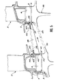
- the first of these abutment portions 39 includes (see Figure 5), on the tabs 38, internal support surfaces 41 on external faces of a crown 42 formed on the side of the disc 31, axial faces 43 bearing abutting against the disc 31, and, on the skin 37, an axial face of stop 44 of the vanes 5 and, an external support face 45 located under shelves 46 projecting from the vanes 5.
- the other of the abutment portions 40 comprises a face axial 47 and an external face 48 of support both in contact with the retaining ring 7 of the blades 5 of the disc 32.
- tabs 38 which do not do not carry these last two faces, may extend from the end adjacent to the disc 31 until either the other end, an intermediate portion of the spacer 36, but it is preferable that it extend as far as possible to form full ventilation channels, as discussed further.
- the support of the internal faces 41 against the crown 42 allows the spacer 36 to be centered on the rotor; the axial faces 43 and 47 of support limit the axial movements of the spacer 36 while providing sufficient flexibility thanks to the intervention of the rod 7; finally, the external radial supports on the faces 45 and 48 are not essential, but can however contribute to perfect the cohesion of assembly and reduce vibration.
- the mounting method consists in assembling the blades 5 to disk 32 by placing rod 7, then to slide the spacer 36 onto the other disc 31 while passing the tabs 38 through the grooves 3, what is illustrated in FIG. 3; then the spacer 36 is rotated to place the tabs 38 in front solid portions of the disc 31 between the pairs of grooves 3 according to Figure 4; so he is possible to install the blades 5 of the disc 31 and to set up by a ring 7 which, unlike the previous design, is placed on the opposite side to the spacer 36.
- Spacer 36 less stressed thermally and mechanically than the previous one thanks omitting the flange 13, could advantageously be constructed of a non-metallic composite material carbon based; we could then make a exception for wipers 17, which would remain metallic as well as the adjacent portions of the skin 37.
- Spacer 36 is suitable for ventilation successive discs 31 and 32 by the same system, can take the following aspect (Figure 2): a flange 49 is bolted to a flange 50 of the disc 31 to the opposite of the spacer 36 to retain the rod 7; he is crossed by lunula 51 for the air intake of ventilation passing between the flange 49 and the flange 50; this air then passes through the grooves 3, under the blade roots 4, attenuating the disc 31, before to flow under the skin 37 in the spacer 36 between the tabs 38; then he walks without obstacle, channeled by the tabs 38, to the disc 32 which it in turn attributes by crossing the grooves 3 under the feet of dawn 4.
- Figure 2 a flange 49 is bolted to a flange 50 of the disc 31 to the opposite of the spacer 36 to retain the rod 7; he is crossed by lunula 51 for the air intake of ventilation passing between the flange 49 and the flange 50; this air then passes through the grooves 3, under the blade roots 4, at
Abstract
Description
L'invention est relative à un agencement de rotor de turbomachine, comprenant en particulier deux disques aubagés séparés par une entretoise affectée à la ventilation ou l'étanchéité.The invention relates to an arrangement of turbomachine rotor, comprising in particular two bladed discs separated by a spacer assigned to ventilation or sealing.
Une construction classique des rotors comprend des disques successifs pourvus de brides amenées en contact mutuel et unies par boulonnage. Des entretoises circulaires entourent les brides. De l'air de ventilation des disques peut circuler sous ces entretoises, et leur surface externe peut porter des agencements d'étanchéité avec des aubes fixes du stator. Les entretoises sont usuellement boulonnées aux brides ; mais cette conception devient impossible si les disques sont conçus pour être fabriqués d'un seul bloc ou soudés, ce qui fait disparaítre les brides.Classic rotor construction includes successive discs with flanges brought into mutual contact and united by bolting. of the circular spacers surround the flanges. Air disc ventilation can flow under these spacers, and their outer surface may bear sealing arrangements with fixed vanes of the stator. The spacers are usually bolted to flanges; but this conception becomes impossible if the discs are designed to be manufactured from a single block or welded, which causes the flanges to disappear.
L'invention est relative à un nouvel agencement de rotor comprenant deux disques consécutifs et une entretoise intermédiaire, qui convienne à des disques associés de façon indémontable et dont les brides boulonnées ont disparu, ce qui oblige à concevoir un autre mode de fixation de l'entretoise.The invention relates to a new rotor arrangement comprising two consecutive discs and an intermediate spacer, which is suitable for disks that cannot be dismantled and whose bolted flanges have disappeared, which requires design another method of fixing the spacer.
Dans la définition la plus générale de l'invention, l'entretoise comprend une peau englobant un des disques (qui est entaillé de rainures de logement de pieds d'aubes), des languettes aptes à coulisser dans les rainures, des faces internes d'appui radial sur des faces complémentaires établies sur un des disques, et des faces extrêmes opposées d'appui axial sur un des disques et sur un joint associé à l'autre des disques.In the most general definition of the invention, the spacer comprises a skin including one of the discs (which is notched with grooves of blade root housing), tabs suitable for slide in the grooves, internal support faces radial on complementary faces established on a discs, and opposite end faces of support axial on one of the discs and on a joint associated with the other of the discs.
On verra plus loin comment cette entretoise satisfait aux exigences d'un montage rigide malgré l'absence de boulonnage sans que ses fonctions d'étanchéité soient compromises, et en améliorant même les possibilités de ventilation des disques. Un autre avantage essentiel qu'on obtient est la simplification de l'agencement, corrélée à une réduction de poids et probablement à une meilleure tenue, en raison de l'union des disques, de la suppression des boulons et d'une rectification favorable de la forme des pièces.We will see later how this spacer meets the requirements for rigid mounting despite the absence of bolting without its functions sealing are compromised, and even improving the possibilities of ventilation of the discs. Another essential advantage obtained is the simplification layout, correlated to weight reduction and probably better hold, due to joining the discs, removing the bolts and a favorable rectification of the shape of the parts.
Dans certaines réalisations plus particulièrement favorables, les faces extrêmes d'appui radial sur un des disques sont situées sur les languettes ; il en est de même des faces internes d'appui radial ; et l'entretoise peut encore comprendre des faces externes d'appui radial sur les zones d'un des disques et sur le joint, pour compléter son montage.In some more realizations particularly favorable, the end faces radial on one of the discs are located on the tabs; the same is true of the internal faces radial support; and the spacer can still understand external faces of radial support on the zones of a discs and on the joint, to complete its mounting.
D'autres aspects, caractéristiques et avantages de l'invention seront encore découverts au moyen des figures suivantes et de leur commentaire :
- la figure 1 est une vue d'une réalisation d'une forme de l'art antérieur relativement proche de l'invention,
- la figure 2 est une vue générale d'un agencement particulier conforme à l'invention,
- les figures 3 et 4 sont deux vues partielles de l'agencement en direction axiale à des instants successifs,
- et la figure 5 illustre les extrémités de jonction de l'entretoise aux disques.
- FIG. 1 is a view of an embodiment of a form of the prior art relatively close to the invention,
- FIG. 2 is a general view of a particular arrangement in accordance with the invention,
- FIGS. 3 and 4 are two partial views of the arrangement in the axial direction at successive times,
- and Figure 5 illustrates the junction ends of the spacer to the discs.
A la figure 1, deux disques 1 et 2
successifs d'un rotor comprennent chacun des rainures 3
axiales ou obliques dans lesquelles sont engagés des
pieds 4 d'aubes 5. Les pieds 4 sont retenus dans les
rainures 3 par leur section bulbeuse et, axialement,
par un jonc 7 fendu retenu dans des crochets 8 des
aubes 5 : en couvrant une partie du disque 1 ou 2, il
retient les aubes 5 d'un côté ; et les mouvements
opposés des aubes 5, qui repousseraient le jonc 7, sont
arrêtés par une collerette 9 ou 10 à l'extrémité d'une
entretoise 11 s'étendant entre les disques 1 et 2 et
contre laquelle s'appuie le jonc 7. L'entretoise 11
comprend essentiellement une peau 12 reliant les
collerettes 9 et 10 et une bride 13 s'étendant à mi-longueur
de la peau 12 et sous elle ; la bride 13 est
enserrée entre des brides 14 et 15 respectivement
jointes aux disques 1 et 2 par des boulons 16. Enfin,
on remarque que la peau 12 porte sur sa face externe
une paire de léchettes 17, qui sont des crêtes
circulaires aptes à venir s'enfoncer dans un anneau 18
de matière abradable attaché à l'extrémité d'un étage
d'aubes fixes 19.In Figure 1, two
Les disques 1 et 2 peuvent être rafraíchis
par une ventilation de gaz originaire d'une autre
partie de la machine, mais un agencement particulier
doit normalement être prévu pour chacun d'eux. La bride
13 de l'entretoise 11 peut ainsi être entaillée entre
des paires de boulons 16 pour y dégager des lunules 20
permettant à du gaz de ventilation injecté dans une
chambre 21 du rotor de s'introduire dans un canal
annulaire 22 s'étendant entre la peau externe 12 de
l'entretoise 11 et une virole de jonction de la bride
15 au disque 2 pour aboutir à celui-ci et l'attiédir
avant de fuir en rejoignant l'écoulement principal dans
la machine. Il est manifeste que la bride 13 contrarie
une ventilation conjointe des disques 1 et 2.
Se reportant à la figure 2, il apparaít que
les disques 1 et 2 sont remplacés par des disques 31 et
32 unis directement par des viroles 33 et 34 soudées
ensemble à un joint 35. Ici encore les disques 31 et 32
sont entaillés de rainures 3 destinés au logement de
pieds 4 d'aubes 5. L'entretoise 11 est remplacée par
une entretoise 36 dépourvue de bride d'attache et
comprenant en particulier : une peau 37 extérieure dont
le diamètre est toujours supérieur à celui du disque 31
le plus petit ; des languettes axiales 38, visibles aux
figures 3 et 4, et dont le pas angulaire correspond à
celui des rainures 3 du disque 31 ou à un multiple de
ce pas ; et des portions extrêmes de butée 39 et 40
associées respectivement aux disques 31 et 32.Referring to Figure 2, it appears that
La première de ces portions de butée 39
comprend (reportez-vous à la figure 5), sur les
languettes 38, des faces internes d'appui 41 sur des
faces externes d'une couronne 42 ménagée sur le côté du
disque 31, des faces axiales 43 d'appui butant contre
le disque 31, et, sur la peau 37, une face axiale de
butée 44 des aubes 5 et, une face externe d'appui 45
située sous des tablettes 46 saillant des aubes 5.
L'autre des portions de butée 40 comprend une face
axiale 47 et une face externe 48 d'appui toutes deux en
contact avec le jonc 7 de rétention des aubes 5 du
disque 32. On notera que les languettes 38, qui ne
portent pas ces deux dernières faces, peuvent s'étendre
depuis l'extrémité adjacente au disque 31 jusqu'à soit
l'autre extrémité, soit une portion intermédiaire de
l'entretoise 36, mais il est préférable qu'elle
s'étendent aussi loin que possible pour former des
canaux de ventilation complets, comme on l'évoquera
plus loin.The first of these
L'appui des faces internes 41 contre la
couronne 42 permet de centrer l'entretoise 36 sur le
rotor ; les faces axiales 43 et 47 d'appui limitent les
mouvements axiaux de l'entretoise 36 tout en offrant
une souplesse suffisante grâce à l'intervention du jonc
7 ; enfin, les appuis radiaux externes sur les faces 45
et 48 ne sont pas indispensables, mais peuvent
cependant contribuer à parfaire la cohésion de
l'assemblage et à réduire les vibrations.The support of the
Le mode de montage consiste à assembler les
aubes 5 au disque 32 en plaçant le jonc 7, puis à
glisser l'entretoise 36 sur l'autre disque 31 en
faisant passer les languettes 38 dans les rainures 3,
ce qu'on illustre à la figure 3 ; puis l'entretoise 36
subit une rotation pour placer les languettes 38 devant
des portions pleines du disque 31 entre les paires de
rainures 3 conformément à la figure 4 ; il est alors
possible d'installer les aubes 5 du disque 31 et de les
mettre en place par un jonc 7 qui, contrairement à la
conception précédente, est placé du côté opposé à
l'entretoise 36.The mounting method consists in assembling the
L'entretoise 36, moins sollicitée
thermiquement et mécaniquement que la précédente grâce
à l'omission de la bride 13, pourrait avantageusement
être construite en un matériau composite non métallique
à base de carbone ; on pourrait alors faire une
exception pour les léchettes 17, qui resteraient
métalliques ainsi que les portions adjacentes de la
peau 37.
L'entretoise 36 se prête à la ventilation
successive des disques 31 et 32 par un même système,
pouvant prendre l'aspect suivant (figure 2) : un
flasque 49 est boulonné à une bride 50 du disque 31 à
l'opposé de l'entretoise 36 pour retenir le jonc 7 ; il
est traversé de lunules 51 pour l'entrée d'air de
ventilation passant entre le flasque 49 et la bride
50 ; cet air passe ensuite dans les rainures 3, sous
les pieds d'aubes 4, attiédissant le disque 31, avant
de s'écouler sous la peau 37 dans l'entretoise 36 entre
les languettes 38 ; puis il se dirige sans obstacle,
canalisé par les languettes 38, jusqu'au disque 32
qu'il attiédit à son tour en traversant les rainures 3
sous les pieds d'aube 4.
La forme conique de la peau 37, dont on est
redevable à l'abolition des brides boulonnées, est
favorable à la tenue mécanique et approche les
léchettes 17 des aubes du stator, ce qui permet de
rendre plus mince le support de l'anneau abradable 18.
Les languettes 38 ont l'effet supplémentaire de raidir
l'entretoise 36.The conical shape of the
Claims (5)
Applications Claiming Priority (2)
| Application Number | Priority Date | Filing Date | Title |
|---|---|---|---|
| FR0107413 | 2001-06-07 | ||
| FR0107413A FR2825748B1 (en) | 2001-06-07 | 2001-06-07 | TURBOMACHINE ROTOR ARRANGEMENT WITH TWO BLADE DISCS SEPARATED BY A SPACER |
Publications (1)
| Publication Number | Publication Date |
|---|---|
| EP1264964A1 true EP1264964A1 (en) | 2002-12-11 |
Family
ID=8864029
Family Applications (1)
| Application Number | Title | Priority Date | Filing Date |
|---|---|---|---|
| EP02291392A Withdrawn EP1264964A1 (en) | 2001-06-07 | 2002-06-06 | Arrangement for turbomachine rotor with two blade discs separated by a spacer |
Country Status (6)
| Country | Link |
|---|---|
| US (1) | US6655920B2 (en) |
| EP (1) | EP1264964A1 (en) |
| JP (1) | JP4094893B2 (en) |
| CA (1) | CA2388778C (en) |
| FR (1) | FR2825748B1 (en) |
| RU (1) | RU2315184C2 (en) |
Cited By (31)
| Publication number | Priority date | Publication date | Assignee | Title |
|---|---|---|---|---|
| EP1637701A1 (en) | 2004-09-21 | 2006-03-22 | Snecma | A monoblock body for a rotor of a gas turbine engine |
| EP2009235A1 (en) | 2007-06-27 | 2008-12-31 | Snecma | Device for cooling the peripheral cavities of a turbomachine rotor disc with double air supply |
| EP2009234A1 (en) * | 2007-06-27 | 2008-12-31 | Snecma | Device for cooling the cavities of a turbomachine rotor disc |
| FR2918414A1 (en) * | 2007-07-06 | 2009-01-09 | Snecma Sa | VENTILATION AIR SUPPLY DEVICE FOR LOW PRESSURE TURBINE BLADES OF A GAS TURBINE ENGINE; SEGMENT FOR AXIAL STOP AND VENTILATION OF LOW PRESSURE TURBINE BLADES |
| FR2926612A1 (en) * | 2008-01-23 | 2009-07-24 | Snecma Sa | Rotor drum for e.g. turbo-jet engine of aircraft, has cooling units at internal surface and at right of sealing elements to exchange heat by convection between wall and cooling and ventilation air circulating inside walls and between disks |
| FR2933442A1 (en) * | 2008-07-04 | 2010-01-08 | Snecma | Flange for maintaining blade retainer ring of rotor disk of low pressure gas turbine engine, has intermediate part comprising wider portion towards fixing edge and radial upstream portion connected to edge and wider portion |
| CN101852100A (en) * | 2009-03-24 | 2010-10-06 | 通用电气公司 | The method and apparatus that is used for turbine interstage seal ring |
| FR2948726A1 (en) * | 2009-07-31 | 2011-02-04 | Snecma | AUBES WHEEL COMPRISING IMPROVED COOLING MEANS |
| FR2953554A1 (en) * | 2009-12-07 | 2011-06-10 | Snecma | Flange for maintaining snap ring of vane of rotor disk of low pressure turbine of e.g. front-fan turbomachine, has free edge comprising mass forming counterweight to be arranged to place free edge on ring under effect of centrifugal force |
| EP2365235A1 (en) * | 2010-03-08 | 2011-09-14 | General Electric Company | Cooled turbine rim seal |
| FR2972759A1 (en) * | 2011-03-15 | 2012-09-21 | Snecma | Wheel for rotor of low pressure turbine in e.g. turbojet of airplane, has annular part defining radial plane to axially support blades and align blades with disk, and tightly maintained against downstream faces of teeth by downstream plate |
| FR2973433A1 (en) * | 2011-04-04 | 2012-10-05 | Snecma | Turbine rotor for low pressure turbomachine e.g. turbojet of aircraft, has upstream and downstream disks arranged coaxially, and bearing unit supporting end portion of flange to prevent deviation of flange of downstream disk |
| EP2256300A3 (en) * | 2009-05-15 | 2012-11-28 | United Technologies Corporation | Knife edge seal assembly and corresponding rotor stage |
| WO2013001240A1 (en) * | 2011-06-30 | 2013-01-03 | Snecma | Labyrinth seal for gas turbine engine turbine |
| DE102012014109A1 (en) * | 2012-07-17 | 2014-01-23 | Rolls-Royce Deutschland Ltd & Co Kg | Washer seal for use in gas turbine engine, has sealing ring, which is arranged between radially outer sections of rotor disks and is clamped between rotor disks in axial direction, where sealing elements are arranged on sealing ring |
| FR2995343A1 (en) * | 2012-09-11 | 2014-03-14 | Snecma | Blade for turbine of turboshaft engine, has upstream spoiler and downstream spoiler including hooks, where hooks are projected to generate axial thrust and include oblique external face presenting groove |
| FR3003599A1 (en) * | 2013-03-25 | 2014-09-26 | Snecma | FIXED AUBAGE OF IMPROVED FLOW DISTRIBUTION |
| FR3019584A1 (en) * | 2014-04-07 | 2015-10-09 | Snecma | SYSTEM FOR VENTILATION OF A TURBINE USING CROSSING ORIFICES AND LUNULES |
| WO2015177429A1 (en) * | 2014-05-20 | 2015-11-26 | Snecma | Turbine rotor for a gas-turbine engine |
| FR3027341A1 (en) * | 2014-10-15 | 2016-04-22 | Snecma | ROTARY ASSEMBLY FOR TURBOMACHINE COMPRISING A SELF-RACKED ROTOR VIROLE |
| EP3020919A1 (en) * | 2014-11-17 | 2016-05-18 | United Technologies Corporation | Fiber reinforced spacer for a gas turbine engine |
| EP3032041A1 (en) * | 2014-12-08 | 2016-06-15 | Alstom Technology Ltd | Rotor heat shield and method for securing the same into a rotor assembly |
| FR3030613A1 (en) * | 2014-12-18 | 2016-06-24 | Snecma | MOBILE TURBINE FOR TURBOMACHINE ORGAN COMPRISING A RIGIDIFICATION RIB |
| EP2551454A3 (en) * | 2011-07-29 | 2016-10-19 | United Technologies Corporation | Low leakage low pressure turbine |
| WO2018065739A1 (en) * | 2016-10-07 | 2018-04-12 | Safran Aircraft Engines | Movable ring assembly for a turbine engine turbine |
| EP3348786A1 (en) * | 2017-01-17 | 2018-07-18 | Siemens Aktiengesellschaft | Rotor with ring cover and seal plates |
| FR3085994A1 (en) | 2018-09-18 | 2020-03-20 | Safran Aircraft Engines | AXIAL RETENTION RING OF BLADES FOR MOBILE WHEEL OF TURBOMACHINE, PREFERABLY FOR AIRCRAFT |
| US11041396B2 (en) | 2016-10-06 | 2021-06-22 | Raytheon Technologies Corporation | Axial-radial cooling slots on inner air seal |
| US11053800B2 (en) | 2018-09-14 | 2021-07-06 | Safran Aircraft Engines | Turbine rotor disk blade having a foot of curvilinear shape |
| US11098604B2 (en) | 2016-10-06 | 2021-08-24 | Raytheon Technologies Corporation | Radial-axial cooling slots |
| FR3120092A1 (en) * | 2021-02-24 | 2022-08-26 | Safran Aircraft Engines | Impeller sealing ring |
Families Citing this family (41)
| Publication number | Priority date | Publication date | Assignee | Title |
|---|---|---|---|---|
| WO1998043621A1 (en) * | 1997-03-31 | 1998-10-08 | The Children's Medical Center Corporation | Nitrosylation to inactivate apoptotic enzymes |
| US6899520B2 (en) * | 2003-09-02 | 2005-05-31 | General Electric Company | Methods and apparatus to reduce seal rubbing within gas turbine engines |
| DE10355230A1 (en) * | 2003-11-26 | 2005-06-23 | Mtu Aero Engines Gmbh | Rotor for a turbomachine |
| FR2875535B1 (en) * | 2004-09-21 | 2009-10-30 | Snecma Moteurs Sa | TURBINE MODULE FOR GAS TURBINE ENGINE |
| WO2007023158A1 (en) * | 2005-08-23 | 2007-03-01 | Alstom Technology Ltd | Device for securing installation of and fixing a heat shield element for a rotor unit of a flow engine |
| JP5049578B2 (en) * | 2006-12-15 | 2012-10-17 | 株式会社東芝 | Steam turbine |
| US8038388B2 (en) * | 2007-03-05 | 2011-10-18 | United Technologies Corporation | Abradable component for a gas turbine engine |
| FR2914008B1 (en) * | 2007-03-21 | 2009-10-09 | Snecma Sa | ROTARY ASSEMBLY OF A TURBOMACHINE BLOWER |
| GB0722511D0 (en) * | 2007-11-19 | 2007-12-27 | Rolls Royce Plc | Turbine arrangement |
| US8388309B2 (en) * | 2008-09-25 | 2013-03-05 | Siemens Energy, Inc. | Gas turbine sealing apparatus |
| US8435007B2 (en) * | 2008-12-29 | 2013-05-07 | Rolls-Royce Corporation | Hybrid turbomachinery component for a gas turbine engine |
| US8235656B2 (en) * | 2009-02-13 | 2012-08-07 | General Electric Company | Catenary turbine seal systems |
| US8348603B2 (en) * | 2009-04-02 | 2013-01-08 | General Electric Company | Gas turbine inner flowpath coverpiece |
| GB2477736B (en) * | 2010-02-10 | 2014-04-09 | Rolls Royce Plc | A seal arrangement |
| US8376689B2 (en) * | 2010-04-14 | 2013-02-19 | General Electric Company | Turbine engine spacer |
| FR2966867B1 (en) * | 2010-10-28 | 2015-05-29 | Snecma | ROTOR DISC ASSEMBLY FOR A TURBOMACHINE |
| IT1403415B1 (en) * | 2010-12-21 | 2013-10-17 | Avio Spa | GAS TURBINE FOR AERONAUTICAL MOTORS |
| US20120301275A1 (en) * | 2011-05-26 | 2012-11-29 | Suciu Gabriel L | Integrated ceramic matrix composite rotor module for a gas turbine engine |
| US20120321437A1 (en) * | 2011-06-17 | 2012-12-20 | General Electric Company | Turbine seal system |
| US8992168B2 (en) | 2011-10-28 | 2015-03-31 | United Technologies Corporation | Rotating vane seal with cooling air passages |
| WO2014100316A1 (en) | 2012-12-19 | 2014-06-26 | United Technologies Corporation | Segmented seal for a gas turbine engine |
| US10094389B2 (en) | 2012-12-29 | 2018-10-09 | United Technologies Corporation | Flow diverter to redirect secondary flow |
| PL2924237T3 (en) | 2014-03-25 | 2019-01-31 | Industria De Turbo Propulsores S.A. | Gas turbine rotor |
| US10036278B2 (en) * | 2014-04-11 | 2018-07-31 | United Technologies Corporation | High pressure compressor thermal shield apparatus and system |
| US10006364B2 (en) * | 2014-08-20 | 2018-06-26 | United Technologies Corporation | Gas turbine rotors |
| RU2712560C2 (en) * | 2014-10-15 | 2020-01-29 | Сафран Серамикс | Rotary assembly for turbine engine comprising self-supporting rotor casing |
| US10662793B2 (en) | 2014-12-01 | 2020-05-26 | General Electric Company | Turbine wheel cover-plate mounted gas turbine interstage seal |
| US10337345B2 (en) | 2015-02-20 | 2019-07-02 | General Electric Company | Bucket mounted multi-stage turbine interstage seal and method of assembly |
| GB201611674D0 (en) * | 2016-07-05 | 2016-08-17 | Rolls Royce Plc | A turbine arrangement |
| FR3057015B1 (en) * | 2016-09-30 | 2018-12-07 | Safran Aircraft Engines | ROTOR DISK HAVING VARIABLE THICKNESS CANVAS |
| US10633992B2 (en) * | 2017-03-08 | 2020-04-28 | Pratt & Whitney Canada Corp. | Rim seal |
| DE102017108581A1 (en) * | 2017-04-21 | 2018-10-25 | Rolls-Royce Deutschland Ltd & Co Kg | Turbomachine with an adaptive sealing device |
| DE102017209420A1 (en) * | 2017-06-02 | 2018-12-06 | MTU Aero Engines AG | Sealing arrangement with welded sealing plate, turbomachine and manufacturing process |
| FR3077327B1 (en) * | 2018-01-30 | 2020-02-21 | Safran Aircraft Engines | TURBOMACHINE TURBINE ASSEMBLY COMPRISING A MOBILE SEAL |
| FR3078363B1 (en) * | 2018-02-23 | 2021-02-26 | Safran Aircraft Engines | MOVABLE SEALING RING |
| FR3092609B1 (en) | 2019-02-12 | 2021-02-12 | Safran Aircraft Engines | TURBINE ASSEMBLY FOR AIRCRAFT TURBOMACHINE WITH IMPROVED DISC COOLING CIRCUIT |
| KR102127429B1 (en) * | 2019-06-05 | 2020-06-26 | 두산중공업 주식회사 | Sealing structure between turbine rotor disk and interstage disk |
| FR3101374B1 (en) * | 2019-09-30 | 2021-09-17 | Safran Aircraft Engines | Cooling structure of a turbine with radial cooperation between sealing ring and moving wheel disc |
| FR3116558B1 (en) * | 2020-11-20 | 2023-06-09 | Safran Aircraft Engines | SET OF TURBOMACHINE ROTOR ELEMENTS EQUIPPED WITH SEALING DEVICE. |
| FR3126141A1 (en) * | 2021-08-11 | 2023-02-17 | Safran Aircraft Engines | IMPROVED VENTILATION TURBINE ROTOR |
| US11933221B2 (en) * | 2021-10-21 | 2024-03-19 | Rtx Corporation | Tongue joint including mating channel for cooling |
Citations (7)
| Publication number | Priority date | Publication date | Assignee | Title |
|---|---|---|---|---|
| US4277225A (en) * | 1977-09-23 | 1981-07-07 | Societe Nationale D'etude Et De Construction De Moteurs D'aviation | Rotor for jet engines |
| US4730982A (en) * | 1986-06-18 | 1988-03-15 | Societe Nationale D'etude Et De Construction De Moteurs D'aviation "S.N.E.C.M.A." | Assembly for controlling the flow of cooling air in an engine turbine |
| US4869640A (en) * | 1988-09-16 | 1989-09-26 | United Technologies Corporation | Controlled temperature rotating seal |
| GB2280478A (en) * | 1993-07-31 | 1995-02-01 | Rolls Royce Plc | Gas turbine sealing assemblies. |
| US5833244A (en) * | 1995-11-14 | 1998-11-10 | Rolls-Royce P L C | Gas turbine engine sealing arrangement |
| EP1013886A2 (en) * | 1998-12-24 | 2000-06-28 | ROLLS-ROYCE plc | Interblade filler platform |
| EP1079070A2 (en) * | 1999-08-26 | 2001-02-28 | Asea Brown Boveri Ag | Heatshield for a turbine rotor |
Family Cites Families (2)
| Publication number | Priority date | Publication date | Assignee | Title |
|---|---|---|---|---|
| US5236302A (en) * | 1991-10-30 | 1993-08-17 | General Electric Company | Turbine disk interstage seal system |
| US5232339A (en) * | 1992-01-28 | 1993-08-03 | General Electric Company | Finned structural disk spacer arm |
-
2001
- 2001-06-07 FR FR0107413A patent/FR2825748B1/en not_active Expired - Lifetime
-
2002
- 2002-05-29 JP JP2002155606A patent/JP4094893B2/en not_active Expired - Fee Related
- 2002-06-03 CA CA2388778A patent/CA2388778C/en not_active Expired - Fee Related
- 2002-06-03 US US10/159,126 patent/US6655920B2/en not_active Expired - Lifetime
- 2002-06-06 EP EP02291392A patent/EP1264964A1/en not_active Withdrawn
- 2002-06-06 RU RU2002115064/06A patent/RU2315184C2/en not_active IP Right Cessation
Patent Citations (7)
| Publication number | Priority date | Publication date | Assignee | Title |
|---|---|---|---|---|
| US4277225A (en) * | 1977-09-23 | 1981-07-07 | Societe Nationale D'etude Et De Construction De Moteurs D'aviation | Rotor for jet engines |
| US4730982A (en) * | 1986-06-18 | 1988-03-15 | Societe Nationale D'etude Et De Construction De Moteurs D'aviation "S.N.E.C.M.A." | Assembly for controlling the flow of cooling air in an engine turbine |
| US4869640A (en) * | 1988-09-16 | 1989-09-26 | United Technologies Corporation | Controlled temperature rotating seal |
| GB2280478A (en) * | 1993-07-31 | 1995-02-01 | Rolls Royce Plc | Gas turbine sealing assemblies. |
| US5833244A (en) * | 1995-11-14 | 1998-11-10 | Rolls-Royce P L C | Gas turbine engine sealing arrangement |
| EP1013886A2 (en) * | 1998-12-24 | 2000-06-28 | ROLLS-ROYCE plc | Interblade filler platform |
| EP1079070A2 (en) * | 1999-08-26 | 2001-02-28 | Asea Brown Boveri Ag | Heatshield for a turbine rotor |
Cited By (55)
| Publication number | Priority date | Publication date | Assignee | Title |
|---|---|---|---|---|
| EP1637701A1 (en) | 2004-09-21 | 2006-03-22 | Snecma | A monoblock body for a rotor of a gas turbine engine |
| US8087879B2 (en) | 2007-06-27 | 2012-01-03 | Snecma | Device for cooling the slots of a rotor disk in a turbomachine having two air feeds |
| EP2009235A1 (en) | 2007-06-27 | 2008-12-31 | Snecma | Device for cooling the peripheral cavities of a turbomachine rotor disc with double air supply |
| EP2009234A1 (en) * | 2007-06-27 | 2008-12-31 | Snecma | Device for cooling the cavities of a turbomachine rotor disc |
| FR2918103A1 (en) * | 2007-06-27 | 2009-01-02 | Snecma Sa | DEVICE FOR COOLING ALVEOLES OF A TURBOMACHINE ROTOR DISK. |
| FR2918104A1 (en) * | 2007-06-27 | 2009-01-02 | Snecma Sa | DEVICE FOR COOLING THE ALVEOLS OF A TURBOMACHINE ROTOR DISC WITH DOUBLE AIR SUPPLY. |
| CN101333937B (en) * | 2007-06-27 | 2013-03-13 | 斯奈克玛 | Device for cooling the cavities of a turbomachine rotor disc |
| US8092152B2 (en) | 2007-06-27 | 2012-01-10 | Snecma | Device for cooling slots of a turbomachine rotor disk |
| US8157506B2 (en) | 2007-07-06 | 2012-04-17 | Snecma | Device for supplying ventilation air to the low pressure blades of a gas turbine engine |
| FR2918414A1 (en) * | 2007-07-06 | 2009-01-09 | Snecma Sa | VENTILATION AIR SUPPLY DEVICE FOR LOW PRESSURE TURBINE BLADES OF A GAS TURBINE ENGINE; SEGMENT FOR AXIAL STOP AND VENTILATION OF LOW PRESSURE TURBINE BLADES |
| EP2011966A3 (en) * | 2007-07-06 | 2010-03-03 | Snecma | Device for supplying ventilation air to the vanes of a low-pressure turbine of a gas turbine engine |
| FR2926612A1 (en) * | 2008-01-23 | 2009-07-24 | Snecma Sa | Rotor drum for e.g. turbo-jet engine of aircraft, has cooling units at internal surface and at right of sealing elements to exchange heat by convection between wall and cooling and ventilation air circulating inside walls and between disks |
| FR2933442A1 (en) * | 2008-07-04 | 2010-01-08 | Snecma | Flange for maintaining blade retainer ring of rotor disk of low pressure gas turbine engine, has intermediate part comprising wider portion towards fixing edge and radial upstream portion connected to edge and wider portion |
| EP2236769A3 (en) * | 2009-03-24 | 2014-02-19 | General Electric Company | Method and apparatus for turbine interstage seal ring |
| CN101852100A (en) * | 2009-03-24 | 2010-10-06 | 通用电气公司 | The method and apparatus that is used for turbine interstage seal ring |
| EP2256300A3 (en) * | 2009-05-15 | 2012-11-28 | United Technologies Corporation | Knife edge seal assembly and corresponding rotor stage |
| US8602734B2 (en) | 2009-07-31 | 2013-12-10 | Snecma | Impeller which includes improved means of cooling |
| FR2948726A1 (en) * | 2009-07-31 | 2011-02-04 | Snecma | AUBES WHEEL COMPRISING IMPROVED COOLING MEANS |
| FR2953554A1 (en) * | 2009-12-07 | 2011-06-10 | Snecma | Flange for maintaining snap ring of vane of rotor disk of low pressure turbine of e.g. front-fan turbomachine, has free edge comprising mass forming counterweight to be arranged to place free edge on ring under effect of centrifugal force |
| EP2365235A1 (en) * | 2010-03-08 | 2011-09-14 | General Electric Company | Cooled turbine rim seal |
| US8382432B2 (en) | 2010-03-08 | 2013-02-26 | General Electric Company | Cooled turbine rim seal |
| FR2972759A1 (en) * | 2011-03-15 | 2012-09-21 | Snecma | Wheel for rotor of low pressure turbine in e.g. turbojet of airplane, has annular part defining radial plane to axially support blades and align blades with disk, and tightly maintained against downstream faces of teeth by downstream plate |
| FR2973433A1 (en) * | 2011-04-04 | 2012-10-05 | Snecma | Turbine rotor for low pressure turbomachine e.g. turbojet of aircraft, has upstream and downstream disks arranged coaxially, and bearing unit supporting end portion of flange to prevent deviation of flange of downstream disk |
| GB2506795A (en) * | 2011-06-30 | 2014-04-09 | Snecma | Labyrinth seal for gas turbine engine turbine |
| FR2977274A1 (en) * | 2011-06-30 | 2013-01-04 | Snecma | LABYRINTH SEAL SEAL FOR TURBINE OF A GAS TURBINE ENGINE |
| WO2013001240A1 (en) * | 2011-06-30 | 2013-01-03 | Snecma | Labyrinth seal for gas turbine engine turbine |
| GB2506795B (en) * | 2011-06-30 | 2018-05-09 | Snecma | Labyrinth seal for gas turbine engine turbine |
| US9683452B2 (en) | 2011-06-30 | 2017-06-20 | Snecma | Labyrinth seal for gas turbine engine turbine |
| EP2551454A3 (en) * | 2011-07-29 | 2016-10-19 | United Technologies Corporation | Low leakage low pressure turbine |
| DE102012014109A1 (en) * | 2012-07-17 | 2014-01-23 | Rolls-Royce Deutschland Ltd & Co Kg | Washer seal for use in gas turbine engine, has sealing ring, which is arranged between radially outer sections of rotor disks and is clamped between rotor disks in axial direction, where sealing elements are arranged on sealing ring |
| FR2995343A1 (en) * | 2012-09-11 | 2014-03-14 | Snecma | Blade for turbine of turboshaft engine, has upstream spoiler and downstream spoiler including hooks, where hooks are projected to generate axial thrust and include oblique external face presenting groove |
| FR3003599A1 (en) * | 2013-03-25 | 2014-09-26 | Snecma | FIXED AUBAGE OF IMPROVED FLOW DISTRIBUTION |
| FR3019584A1 (en) * | 2014-04-07 | 2015-10-09 | Snecma | SYSTEM FOR VENTILATION OF A TURBINE USING CROSSING ORIFICES AND LUNULES |
| FR3021348A1 (en) * | 2014-05-20 | 2015-11-27 | Snecma | TURBINE ROTOR FOR A GAS TURBINE ENGINE |
| US10526893B2 (en) | 2014-05-20 | 2020-01-07 | Safran Aircraft Engines | Turbine rotor for a gas turbine engine |
| CN106460521A (en) * | 2014-05-20 | 2017-02-22 | 赛峰航空器发动机 | Turbine rotor for a gas-turbine engine |
| WO2015177429A1 (en) * | 2014-05-20 | 2015-11-26 | Snecma | Turbine rotor for a gas-turbine engine |
| FR3027341A1 (en) * | 2014-10-15 | 2016-04-22 | Snecma | ROTARY ASSEMBLY FOR TURBOMACHINE COMPRISING A SELF-RACKED ROTOR VIROLE |
| EP3020919A1 (en) * | 2014-11-17 | 2016-05-18 | United Technologies Corporation | Fiber reinforced spacer for a gas turbine engine |
| US10648481B2 (en) | 2014-11-17 | 2020-05-12 | United Technologies Corporation | Fiber reinforced spacer for a gas turbine engine |
| US10156141B2 (en) | 2014-12-08 | 2018-12-18 | Ansaldo Energia Switzerland AG | Rotor heat shield and method for securing the same into a rotor assembly |
| EP3032041A1 (en) * | 2014-12-08 | 2016-06-15 | Alstom Technology Ltd | Rotor heat shield and method for securing the same into a rotor assembly |
| FR3030613A1 (en) * | 2014-12-18 | 2016-06-24 | Snecma | MOBILE TURBINE FOR TURBOMACHINE ORGAN COMPRISING A RIGIDIFICATION RIB |
| US11098604B2 (en) | 2016-10-06 | 2021-08-24 | Raytheon Technologies Corporation | Radial-axial cooling slots |
| US11041396B2 (en) | 2016-10-06 | 2021-06-22 | Raytheon Technologies Corporation | Axial-radial cooling slots on inner air seal |
| CN109844264A (en) * | 2016-10-07 | 2019-06-04 | 赛峰飞机发动机公司 | Energy moving ring assembly for turbogenerator turbine |
| US10920593B2 (en) | 2016-10-07 | 2021-02-16 | Safran Aircraft Engines | Movable ring assembly for a turbine engine turbine |
| CN109844264B (en) * | 2016-10-07 | 2021-04-30 | 赛峰飞机发动机公司 | Active ring assembly for turbine of turbine engine |
| FR3057300A1 (en) * | 2016-10-07 | 2018-04-13 | Safran Aircraft Engines | MOBILE RING ASSEMBLY OF TURBOMACHINE TURBINE |
| WO2018065739A1 (en) * | 2016-10-07 | 2018-04-12 | Safran Aircraft Engines | Movable ring assembly for a turbine engine turbine |
| EP3348786A1 (en) * | 2017-01-17 | 2018-07-18 | Siemens Aktiengesellschaft | Rotor with ring cover and seal plates |
| US11053800B2 (en) | 2018-09-14 | 2021-07-06 | Safran Aircraft Engines | Turbine rotor disk blade having a foot of curvilinear shape |
| FR3085994A1 (en) | 2018-09-18 | 2020-03-20 | Safran Aircraft Engines | AXIAL RETENTION RING OF BLADES FOR MOBILE WHEEL OF TURBOMACHINE, PREFERABLY FOR AIRCRAFT |
| FR3120092A1 (en) * | 2021-02-24 | 2022-08-26 | Safran Aircraft Engines | Impeller sealing ring |
| WO2022180330A1 (en) * | 2021-02-24 | 2022-09-01 | Safran Aircraft Engines | Turbine sealing ring |
Also Published As
| Publication number | Publication date |
|---|---|
| RU2315184C2 (en) | 2008-01-20 |
| JP2003003801A (en) | 2003-01-08 |
| CA2388778C (en) | 2011-02-08 |
| JP4094893B2 (en) | 2008-06-04 |
| FR2825748A1 (en) | 2002-12-13 |
| US20020187046A1 (en) | 2002-12-12 |
| FR2825748B1 (en) | 2003-11-07 |
| US6655920B2 (en) | 2003-12-02 |
| CA2388778A1 (en) | 2002-12-07 |
Similar Documents
| Publication | Publication Date | Title |
|---|---|---|
| EP1264964A1 (en) | Arrangement for turbomachine rotor with two blade discs separated by a spacer | |
| EP0370899B1 (en) | Turbine-bladed rotor disc | |
| CA2387462C (en) | Centripetal flow air bleed device | |
| BE1022361B1 (en) | Mixed axial turbine engine compressor stator. | |
| EP2344719B1 (en) | Annular flange for fixing rotor or stator components in a turbomachine | |
| EP2469100B1 (en) | Motorcompressor unit with torsionally flexible coupling placed in a hollow shaft of the compressor | |
| EP0636766B1 (en) | Turbomachine with variable guide vanes and actuator ring | |
| FR2580033A1 (en) | Elastically suspended turbine ring for a turbine machine | |
| EP0696675A1 (en) | Assembly device for a circular row of variable guide vanes | |
| FR2939470A1 (en) | BLOWER FOR TURBOMACHINE COMPRISING A BALANCING SYSTEM HAVING MOUNTED HOUSING HOUSES | |
| CA2472934C (en) | Improved linkage between bladed disks on the rotor line of a compressor | |
| EP0214876B1 (en) | Multifunctional support disc for a labyrinth seal of a turbo machine rotor | |
| FR2918409A1 (en) | Rotating part i.e. fan, for turbine engine of aircraft, has blade with circumferential projection detected in continuity of adjacent platform forming sector, where projection participates in definition of inter-blade surface | |
| EP3023595A1 (en) | Internal ferrule of an axial turbine-engine compressor | |
| EP2366061A1 (en) | Turbine wheel with an axial retention system for vanes | |
| FR2988787A1 (en) | VARIABLE TIMING RECTIFIER FOR TURBOMACHINE COMPRESSOR COMPRISING TWO INTERNAL RINGS | |
| WO2014001681A1 (en) | Pivot pin for a turbine engine comprising a ring for recovering a flow of lubricating oil with a plurality of lubricating oil discharge ports | |
| EP1662093B1 (en) | Zusammenbau von Leitsegmente in einem axialen Kompressor | |
| FR2990001A1 (en) | Intermediate casing for turbojet, has fixing ring for assembling intermediate casing with thrust reverser casing, where fixing ring includes radial annular leg, and heat exchanger is partly fixed to radial annular leg | |
| EP0669451A1 (en) | Seal between the blades and the intermediate platforms | |
| EP1329589A1 (en) | Rotor configuration for a turbomachine | |
| FR2535389A1 (en) | DEVICE FOR MOUNTING, ON THEIR CARRIER DISC, PROFILED BLADES FOR COMPRESSOR OR TURBINE | |
| FR2504209A1 (en) | Radial turbine impeller - has metallic hub and inlet vanes with impeller vanes in oriented synthetic fibre | |
| EP3677752A1 (en) | Improved seal assembly for an inter-blade platform | |
| FR2648638A1 (en) | IMPROVEMENTS IN TRANSMISSIONS OF VEHICLES EQUIPPED WITH ELECTRIC RETARDERS |
Legal Events
| Date | Code | Title | Description |
|---|---|---|---|
| PUAI | Public reference made under article 153(3) epc to a published international application that has entered the european phase |
Free format text: ORIGINAL CODE: 0009012 |
|
| 17P | Request for examination filed |
Effective date: 20020613 |
|
| AK | Designated contracting states |
Kind code of ref document: A1 Designated state(s): AT BE CH CY DE DK ES FI FR GB GR IE IT LI LU MC NL PT SE TR |
|
| AX | Request for extension of the european patent |
Free format text: AL;LT;LV;MK;RO;SI |
|
| 17Q | First examination report despatched |
Effective date: 20030403 |
|
| AKX | Designation fees paid |
Designated state(s): DE ES FR GB IT SE |
|
| STAA | Information on the status of an ep patent application or granted ep patent |
Free format text: STATUS: THE APPLICATION IS DEEMED TO BE WITHDRAWN |
|
| 18D | Application deemed to be withdrawn |
Effective date: 20030814 |