EP1262609A1 - Floor covering element with sealing strip - Google Patents
Floor covering element with sealing strip Download PDFInfo
- Publication number
- EP1262609A1 EP1262609A1 EP20020291309 EP02291309A EP1262609A1 EP 1262609 A1 EP1262609 A1 EP 1262609A1 EP 20020291309 EP20020291309 EP 20020291309 EP 02291309 A EP02291309 A EP 02291309A EP 1262609 A1 EP1262609 A1 EP 1262609A1
- Authority
- EP
- European Patent Office
- Prior art keywords
- seal
- elements
- layer
- joint
- interlocking
- Prior art date
- Legal status (The legal status is an assumption and is not a legal conclusion. Google has not performed a legal analysis and makes no representation as to the accuracy of the status listed.)
- Granted
Links
Images


Classifications
-
- E—FIXED CONSTRUCTIONS
- E04—BUILDING
- E04F—FINISHING WORK ON BUILDINGS, e.g. STAIRS, FLOORS
- E04F15/00—Flooring
- E04F15/02—Flooring or floor layers composed of a number of similar elements
-
- E—FIXED CONSTRUCTIONS
- E04—BUILDING
- E04F—FINISHING WORK ON BUILDINGS, e.g. STAIRS, FLOORS
- E04F15/00—Flooring
- E04F15/02—Flooring or floor layers composed of a number of similar elements
- E04F15/04—Flooring or floor layers composed of a number of similar elements only of wood or with a top layer of wood, e.g. with wooden or metal connecting members
-
- E—FIXED CONSTRUCTIONS
- E04—BUILDING
- E04F—FINISHING WORK ON BUILDINGS, e.g. STAIRS, FLOORS
- E04F2201/00—Joining sheets or plates or panels
- E04F2201/01—Joining sheets, plates or panels with edges in abutting relationship
- E04F2201/0107—Joining sheets, plates or panels with edges in abutting relationship by moving the sheets, plates or panels substantially in their own plane, perpendicular to the abutting edges
- E04F2201/0115—Joining sheets, plates or panels with edges in abutting relationship by moving the sheets, plates or panels substantially in their own plane, perpendicular to the abutting edges with snap action of the edge connectors
-
- E—FIXED CONSTRUCTIONS
- E04—BUILDING
- E04F—FINISHING WORK ON BUILDINGS, e.g. STAIRS, FLOORS
- E04F2201/00—Joining sheets or plates or panels
- E04F2201/07—Joining sheets or plates or panels with connections using a special adhesive material
Definitions
- the invention relates to a floor covering element, multilayer, laid floating, that is to say not secured to the slab or the structure to be clad with the building that we want to equip.
- the invention relates to the field of floating poses in which typically a underlay (felt, carpet, ...) or a foam sheet is interposed between the covering and the floor.
- the covering is fixed (typically glued) on the ground on a slab (often a patched slab covered with a fluid coating forming a bonding bed).
- an object of the invention is to improve the resistance to the humidity of the coating and more generally, the resistance over time of the element once installed, the risk being that substances will flow or pile up between two joined elements, risking damage.
- an important characteristic of the invention provides the seal has an adhesive front face to stick against the side in look of the other element, in the mutually locked position of the first and second elements.
- Another object of the invention is to ensure positioning also perfect as possible of the two adjacent elements, while promoting the holding and joint control.
- the element provided with the seal has a length with, along this length, a joint made up of a succession of joint sections with a interruption between two successive sections.
- another characteristic of the invention advises that the joint can be presented as a flange having a naturally erect wing along the edge of the element to which it is attached.
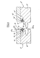
- Two such elements, 1, 3, typically called boards or slats, are linked together during installation, by interlocking means materialized here by a male element 15 for element 3 and one per element complementary female 17, for element 1.
- the two means 15, 17, are located on at least one of the sides, such as 19a and 19'a of the elements concerned, at the location of at least one of their edge (vertical).
- system clip acting by interlocking and elastic wedging.
- Either of these interlocking means 15, 17 is (are) topped by at least one seal such as 21.
- the seal 21 is a seal for liquids which is housed at the level of the second layer 9.
- This seal seals when it is pressed against the side in look of the adjacent element, i.e. when the two elements 1, 3, are interlocked, and therefore blocked by fitting 15 into 17, the joint then being in a projecting position, between the elements.
- the joint used is a malleable polyolefin adhesive (can be crushed more or less elastic at room temperature) and having a power sticky higher than a temperature close to its temperature of softening (melting) only at room temperature. At this temperature, ambient, it can stick repeatedly.
- the seal is placed hot on the slice of the slat to which it must adhere. It is therefore placed just above of the interlocking zone 41, at the location of the support layer 9 underlying the wear layer 5. Its temperature at the outlet of the removal is between 160 ° C and 220 ° C (to within 10 ° C).
- the cord (full) deposited by this nozzle progresses between 15 m / min and 25 m / min (to within 20%) and deposit between 0.1 g and 1.5 g / mL (linear meter). Once glued to this slice, let the cord cool.
- the interlocking created by the cooperation (snap-in) of male and female elements 15, 17, causes adhesion of the seal to the edge of the adjacent slat which comes to press against it.
- the pressure exerted during of this contact is between approximately 1.5 kg / cm and 7 kg / cm (typically, approximately 2 to 4 kg / cm for a layer of HDF and approximately 4 to 6 kg / cm for a layer 9 of softwood batten).
- hot melt polyolefin based glue hot melt polyolefin glue
- pressure sensitive hot melt polyolefin based glue thermoplastic, in particular of polypropylene, for its reliability and ease of installation advantages artwork.
- the bead forming the joint can be continuous or discontinuous, depending on the degree of tightness desired.
- the wall can be plane.
- a protrusion 25 has been arranged in projection on the edge 19'a, at the level of the second layer 9, opposite said joint, now marked 21 '.
- this hard, rigid outgrowth (typically based of wood if it was formed from material with layer 9) has been made towards the lower part of the seal when it is in position (or in a state) no active as in FIG. 2, the protuberance 25 having even been here conformed and arranged to block any possible downward movement of the seal when is overwritten in the active position as in Figure 3.
- the projection 25 shown in view enlarged in FIG. 4 presents an upper face 25a overall oblique to line 100 embodying the general plane in which extend the elements (see Figure 7), but also present, at the place of its free apex 25b a projection which defines an obstacle preventing any exit from the joint downwards, the apex then being located at the end lower joint when the two elements 1, 3, are fitted as on the figure 3.
- the (each) seal such as 21 ' is preferably housed in a cavity 27 formed, in FIG. 2, in hollow relative to the general vertical plane of the section 19a.
- the seal 21 ' of Figure 2 is a hollow joint (which can typically appear as a tubular tube) mechanically forcibly engaged in an orifice 29 formed in the bottom of the cavity 27. Notches 31 effectively retain the seal which, in this non-active position, protrudes clearly outside the cavity, the empty interior space 33a of its bead portion 33 allowing it to be effectively crushed and deformed when interlocking the elements.
- the seal 21 'further has an upright upper wing 35 which extends to the level of the upper layer 5 against which it is supported, favoring an effective positioning of the joint in its active state.
- At least the front face 37 of the rod portion of the seal is adhesive so that the seal sticks against the area opposite the edge 19'a.
- a gap 39 remains above the zone 19a 1 , this gap extending, with a reduced width (see d 2 with respect to d 1 in FIG. 3) over the entire height of the first layer 5 of each of the elements.
- the seal 21, then in the crushed active position extends essentially above the level of the apex 25b, a marginal part of the seal extending below, but only up to the place of the upper limit of the support area 19a 1 , thus avoiding any interference between the sealing area of the gap 39 and the interlocking area 41 bordered above and below by the contact areas 19a 1 and 19a 2 .
- wing 35 which provides a stabilization of the joint during its deformation and increases the tightness at the place of the upper layer 5.
- This wing 35 extends (at least essentially) to the look of this upper layer 5, while the tubular bead 33 extends at the location of the gap 39, at the second layer 9, this both in the active and inactive state of the seal.
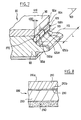
- Figure 6 shows that the (each) joint element may overflow from this cavity, in the non-active state of said seal.
- each joint part is curved outwards and overflows from the corresponding cavity, 55, 55 'respectively.
- Each part of the joint is linked to the location of its zone back (for example, by adhesion) to an insert (respectively 57, 57 ') anchored in the thickness of the second layer 9 "of each element 1", 3 ", of covering ready to be assembled.
- the anchoring can be carried out by a notched end, respectively 59, 59 ', forcibly engaged.
- the two cavities and the two joint parts face each other and are located on the same level.
- the control of the upward deformation of the joint is less precise.
- the design of the contact zone 19 "a 1 is adapted to prevent the seals from descending clearly in the direction of the interlocking zone 41".
- the gap 61 with a depth of 2 (relative to the slightly protruding end of the wall 19 "a 1 ) reserved above the joint 51 up to the upper surface 5" a allows the two elements to seal 51, 51 ', to naturally take their active compressed position above said zone 19 "to 1 .
- the projecting front part 53, 53 ′ of said seals will be coated with a protective film (not shown to avoid overload the figure).
- the perspective therefore makes it possible to show the plane (in general typically horizontal) 100 in which each covering element, such as that partially shown in this figure and identified 20.
- the figure shows the male locking element 115 formed of material, projecting, at the level of the second layer 90. Above the bead interlocking 115 extends the area 119 of contact between the elements of coating, preventing the seal 125 still located above from reaching the area of the bead 115, in the compressed active state of the joint, when the bead 115 is locked.
- the seal 125 is interrupted (in its non-active state) before having reached the level of the first upper layer 50 of the element 20.
- the front face 50a of this layer 5 thus that the part of the front face 90a of the second layer 90 which extends it in the same vertical are offset in depth by a distance d 20 relative to the vertical plane in which the wall 119 extends, so as to reserve a gap 610 for deploying the seal 125 when the element 20 is locked to its adjacent complementary element, as shown in FIG. 3.
- FIG. 7 An additional interest of figure 7 is to show that the joint 125 extends horizontally, parallel to the general plane 100, to the like a housed band (in this case entirely in its inactive state) in the cavity 270 hollowed out on the front surface of the second layer 90.
- the joint 125 has a length horizontally, materialized here by the frame L and, along this length, looks like a succession of joint sections, such as 125a, 125b, with an interruption, such as 150a, 150b, between two adjacent sections.
- each joint can be a sticky putty ("adhesive, hot melt putty ").
Abstract
Description
L'invention concerne un élément de revêtement de sol, multicouche, posé flottant, c'est-à-dire non solidarisé avec la dalle ou la structure à revêtir du bâtiment que l'on veut équiper.The invention relates to a floor covering element, multilayer, laid floating, that is to say not secured to the slab or the structure to be clad with the building that we want to equip.
En particulier, l'invention concerne un revêtement consistant en un élément, ou un ensemble d'éléments :
- d'un "vrai parquet" dont la couche de surface est (essentiellement) en bois et se présente sous la forme d'une ou plusieurs lame(s) (également appelées planches, frises, lattes, ...),
- ou d'un "similiparquet" (appelé également "faux parquet" ou "laminé", c'est-à-dire un revêtement ayant l'aspect d'un parquet mais contenant beaucoup moins de bois qu'un "vrai parquet"), tant le parquet que le similiparquet étant à poser flottant.
- a "real parquet" whose surface layer is (essentially) wooden and is in the form of one or more plank (s) (also called boards, friezes, slats, ...),
- or a "similiparquet" (also called "false parquet" or "laminate", that is to say a coating having the appearance of a parquet but containing much less wood than a "real parquet") , both the parquet and the faux-parquet being floating.
Dans le domaine de ces revêtements, deux techniques de pose sont privilégiées :
- les poses flottantes,
- les poses collées.
- floating poses,
- the poses glued.
Comme on 1'a compris, l'invention se rapporte au domaine des poses flottantes dans lequel typiquement une thibaude (feutre, moquette,...) ou une feuille de mousse est interposée entre le revêtement et le sol.As will be understood, the invention relates to the field of floating poses in which typically a underlay (felt, carpet, ...) or a foam sheet is interposed between the covering and the floor.
Dans l'autre technique, le revêtement est fixé (typiquement collé) au sol sur une dalle (souvent une dalle ragréée recouverte d'un enduit fluide formant un lit de collage).In the other technique, the covering is fixed (typically glued) on the ground on a slab (often a patched slab covered with a fluid coating forming a bonding bed).
En l'espèce, un objet de l'invention est d'améliorer la résistance à l'humidité du revêtement et plus généralement, la tenue dans le temps de l'élément une fois posé, le risque étant que des substances viennent couler ou s'amasser entre deux éléments joints, risquant d'entraíner des dégradations.In the present case, an object of the invention is to improve the resistance to the humidity of the coating and more generally, the resistance over time of the element once installed, the risk being that substances will flow or pile up between two joined elements, risking damage.
Dans le domaine général des revêtements à poser flottant, on connaít déjà des éléments multicouches présentant plusieurs côtés, une tranche, s'étendant dans un plan général et comprenant :
- une première couche rigide dure, présentant une face supérieure visible,
- et au moins une deuxième couche sous-jacente mécaniquement résistante, rigide, de support de la première couche, cette deuxième couche sous-jacente comprenant des moyens d'interverrouillage adaptés pour coopérer mécaniquement avec des moyens complémentaires d'interverrouillage dont est pourvu un deuxième élément adapté pour coopérer avec le premier et qui comprend les mêmes dites première et seconde couches, la deuxième couche du premier ou du deuxième élément comprenant en outre un joint déformable fixé à elle , sur au moins l'un de ses côtés à l'écart des moyens d'interverrouillage qui y sont prévus et en regard de l'autre élément, le joint étant adapté pour assurer, dans une position en saillie sur la tranche, une étanchéité aux liquides lorsqu'il est écrasé contre ledit côté en regard de l'autre élément par rapprochement des premier et deuxième éléments et verrouillage mutuel entre eux.
- a first hard rigid layer, having a visible upper face,
- and at least one second mechanically strong, rigid underlying second layer for supporting the first layer, this second underlying layer comprising interlocking means adapted to mechanically cooperate with complementary interlocking means which is provided with a second element adapted to cooperate with the first and which comprises the same said first and second layers, the second layer of the first or of the second element further comprising a deformable seal fixed to it, on at least one of its sides away from the interlocking means provided therein and facing the other element, the seal being adapted to ensure, in a projecting position on the edge, a liquid tightness when it is crushed against said side facing the another element by bringing together the first and second elements and mutual locking between them.
Un problème se pose en liaison avec la manière de réaliser et/ou de mettre en place le joint pour accroítre l'efficacité de l'étanchéité, la facilité de mise en oeuvre du joint, en diminuant les coûts.A problem arises in connection with the manner of carrying out and / or to set up the seal to increase the effectiveness of the seal, the ease implementation of the seal, reducing costs.
Dans ce but, une caractéristique importante de l'invention prévoit que le joint présente une face frontale adhésive pour coller contre le côté en regard de l'autre élément, en position de verrouillage mutuel des premier et deuxième éléments.To this end, an important characteristic of the invention provides the seal has an adhesive front face to stick against the side in look of the other element, in the mutually locked position of the first and second elements.
Définir la nature du joint s'est avéré important pour renforcer les critères précités.Defining the nature of the joint proved to be important for strengthening the above criteria.
Aussi conseille-t-on la reproduction alternative ou combinée des caractéristiques suivantes :
- le joint est une colle polyoléfine malléable, ayant un pouvoir collant supérieur à une température proche de sa température de ramollissement qu'à température ambiante,
- le joint est collé plus solidement au premier élément qu'au second élément, et est collable et décollable de façon répétitive à ce second élément, à température ambiante,
- le joint est un cordon malléable collant thermoplastique, en particulier en polypropylène, pouvant coller de façon répétitive à température ambiante.
- the seal is a malleable polyolefin adhesive, having a higher tack at a temperature close to its softening temperature than at room temperature,
- the seal is stuck more securely to the first element than to the second element, and is repeatedly stickable and peelable from this second element, at room temperature,
- the joint is a malleable, adhesive thermoplastic bead, in particular made of polypropylene, which can bond repeatedly at room temperature.
Un autre objet de l'invention est d'assurer un positionnement aussi parfait que possible des deux éléments adjacents, tout en favorisant la tenue et le contrôle du joint.Another object of the invention is to ensure positioning also perfect as possible of the two adjacent elements, while promoting the holding and joint control.
Aussi est-il conseillé que :
- l'un au moins des éléments présente sur au moins un de ses côtés, une forme en creux où est disposé le joint,
- et l'autre élément présente en regard de la forme en creux une excroissance adaptée pour qu'une partie au moins du joint soit déformée par cette excroissance lors de l'interverrouillage des éléments.
- at least one of the elements present on at least one of its sides, a hollow shape where the seal is placed,
- and the other element has, opposite the hollow form, a protuberance adapted so that at least part of the joint is deformed by this protrusion during the interlocking of the elements.
Dans l'invention, il est en outre à noter qu'une attention particulière a été portée à la position du joint, à l'efficacité de sa fonction vis-à-vis de la constitution structurelle de chaque élément et vis-à-vis de la manière dont ces derniers sont réunis entre eux par leurs moyens d'interverrouillage.In the invention, it is further noted that an attention particular attention was paid to the position of the seal, to the efficiency of its function vis-à-vis of the structural constitution of each element and vis-à-vis the how they are brought together by their means interlock.
Aussi, une caractéristique de l'invention conseille que :
- le joint soit disposé, sur l'un desdits éléments, exclusivement au-dessus des moyens d'interverrouillage, au niveau de la deuxième couche,
- et que les moyens d'interverrouillage de ces éléments, eux-mêmes situés au niveau de cette deuxième couche, se verrouillent mutuellement par emboítement, dans une première position de blocage relatif des éléments suivant une direction parallèle ou sensiblement parallèle au plan général alors commun desdits éléments, lesquels sont déverrouillables à partir de leur dite première position de blocage, par décalage en hauteur d'un élément par rapport à l'autre, tel par exemple qu'une inclinaison d'un élément par rapport à l'autre,
- et le joint, lié fixement au premier élément, adhère à l'autre élément sous une pression créée par l'interverrouillage des deux éléments comprise entre 1,5 kg/cm et 7 kg/cm, environ (à 10 % près).
- the seal is disposed, on one of said elements, exclusively above the interlocking means, at the level of the second layer,
- and that the means for interlocking these elements, themselves located at the level of this second layer, interlock with each other by interlocking, in a first position of relative locking of the elements in a direction parallel or substantially parallel to the general then common plane of said elements, which are unlockable from their said first locking position, by offset in height of one element with respect to the other, such as for example an inclination of one element with respect to the other,
- and the seal, fixedly linked to the first element, adheres to the other element under a pressure created by the interlocking of the two elements of between 1.5 kg / cm and 7 kg / cm, approximately (to within 10%).
Encore pour favoriser un positionnement particulièrement efficace du joint en position active, on conseille en outre :
- que l'excroissance présente une face supérieure globalement oblique par rapport au plan général de l'(des) élément(s) considéré(s), cette face se terminant par un apex libre situé en regard d'une partie de la cavité qui lui fait face, en position de blocage, pour solliciter le joint à se déformer au moins partiellement vers le haut,
- et, dans ce cas, que l'excroissance, à l'endroit de son apex, puisse présenter une saillie qui définisse un obstacle interdisant une sortie du joint vers le bas.
- that the protrusion has a generally oblique upper face with respect to the general plane of the element (s) considered, this face ending in a free apex situated opposite a part of the cavity which faces, in the locked position, to urge the seal to deform at least partially upwards,
- and, in this case, that the protuberance, at the place of its apex, can present a projection which defines an obstacle preventing an exit of the joint downwards.
Ainsi, on limite les risques d'interférence (coincement, ...) avec la zone où sont constitués les moyens d'interverrouillage et on favorise l'effet protecteur assuré vis-à-vis du joint.This limits the risk of interference (jamming, ...) with the zone where the interlocking means are made up and the effect is favored protector assured against the seal.
Pour favoriser par ailleurs la prise en compte des dilatations et autres mouvements possibles au sein d'un élément ou entre éléments adjacents réunis, on conseille par ailleurs que, suivant son plan général, l'élément pourvu du joint présente une longueur avec, suivant cette longueur, un joint constitué en une succession de tronçons de joint avec une interruption entre deux tronçons successifs.To also encourage the consideration of dilations and other possible movements within an element or between elements adjacent, we also advise that, according to its general plan, the element provided with the seal has a length with, along this length, a joint made up of a succession of joint sections with a interruption between two successive sections.
Dans un mode de réalisation favorable, alliant un bon contrôle en déformation et une bonne efficacité en étanchéité, une autre caractéristique de l'invention conseille que le joint puisse se présenter comme un boudin présentant une aile naturellement dressée le long de la tranche de l'élément auquel il est fixé. In a favorable embodiment, combining good control in deformation and good sealing efficiency, another characteristic of the invention advises that the joint can be presented as a flange having a naturally erect wing along the edge of the element to which it is attached.
Une description plus détaillée de l'invention va maintenant être fournie en relation avec les dessins annexés dans lesquels :
- la figure 1 montre, en coupe, deux éléments adjacents de revêtement de sol, dans un état non verrouillé, en regard l'un de l'autre,
- la figure 2 montre une variante de réalisation de la figure 1,
- la figure 3 montre les éléments de la figure 2 dans leur état verrouillé,
- la figure 4 montre le détail IV de la figure 2, en vue agrandie,
- la figure 5 montre le joint de la figure 2 seul, en vue agrandie,
- la figure 6 montre une autre alternative de réalisation, toujours dans l'état face à face, non verrouillé des deux éléments de revêtement,
- la figure 7 montre, en vue agrandie, une perspective locale d'un élément de revêtement pourvu d'un joint d'étanchéité allongé, en forme de ruban discontinu,
- et la figure 8 montre schématiquement, en coupe, un "faux-parquet" ou "laminé".
- FIG. 1 shows, in section, two adjacent elements of floor covering, in an unlocked state, facing each other,
- FIG. 2 shows an alternative embodiment of FIG. 1,
- FIG. 3 shows the elements of FIG. 2 in their locked state,
- FIG. 4 shows the detail IV of FIG. 2, in an enlarged view,
- FIG. 5 shows the seal of FIG. 2 alone, in enlarged view,
- FIG. 6 shows another alternative embodiment, still in the face to face, unlocked state of the two covering elements,
- FIG. 7 shows, in an enlarged view, a local perspective of a covering element provided with an elongated seal, in the form of a discontinuous tape,
- and Figure 8 shows schematically, in section, a "false parquet" or "laminate".
Sur la figure 1, on voit deux éléments adjacents de revêtement de
sol 1, 3, de type "vrai parquet".In Figure 1, we see two adjacent elements of coating of
Ainsi, chaque élément comprend :
- une couche supérieure (ou couche d'usure) rigide, dure et
pleine 5, contenant du bois (typiquement constituée de bois), présentant une face supérieure d'aspect visible et continu 5a, cette couche supérieure (typiquement d'une épaisseur compriseentre - une deuxième couche sous-jacente, 9, de support de la couche
supérieure, située immédiatement sous elle, cette deuxième couche qui est en
un matériau rigide contenant du bois (y compris les particules agglomérées)
pouvant être continue ou discontinue (en présentant alors une série de fentes
susceptibles d'être formées par des tasseaux espacés les uns des autres), cette
deuxième couche ayant typiquement une épaisseur comprise
entre 0,3 mm et 8 mm, - avantageusement, une couche pleine de contrebalancement 11,
dure, contenant du bois (y compris les particules agglomérées) et s'étendant
alors (lorsqu'elle existe) immédiatement sous la seconde couche 9, pour la
tenue mécanique du parquet dans son ensemble, et tout particulièrement de
la couche supérieure 5 (épaisseur comprise
entre 0,1 mm et 5 mm), - et/ou une couche d'insonorisation 13 (voir figure 2), en un matériau acoustiquement absorbant (mousse, masse lourde, ...) située soit directement sous la couche de contrebalancement 11, soit directement sous la seconde couche 9 (étant précisé que, hormis cette couche d'insonorisation 13, qui peut être rapportée après fabrication, les autres sont liées ensemble au moment de la fabrication du parquet, typiquement par collage sous pression).
- a rigid, hard and solid upper layer (or wear layer) 5, containing wood (typically made of wood), having an upper face of visible and
continuous appearance 5a, this upper layer (typically of a thickness between 1.5 mm and 10 mm) which can be covered with a protective layer, such as varnish, oil or wax, 7, - a second underlying layer, 9, for supporting the upper layer, located immediately beneath it, this second layer which is made of a rigid material containing wood (including agglomerated particles) can be continuous or discontinuous (thus presenting a series of slots capable of being formed by battens spaced apart from each other), this second layer typically having a thickness of between 0.3 mm and 8 mm,
- advantageously, a
solid counterbalancing layer 11, hard, containing wood (including agglomerated particles) and then extending (when it exists) immediately under thesecond layer 9, for the mechanical strength of the parquet as a whole, and most particularly of the upper layer 5 (thickness between 0.1 mm and 5 mm), - and / or a soundproofing layer 13 (see FIG. 2), made of an acoustically absorbent material (foam, heavy mass, etc.) situated either directly under the counterbalancing
layer 11, or directly under the second layer 9 (being specified that, apart from thissoundproofing layer 13, which can be added after manufacture, the others are linked together at the time of manufacture of the parquet, typically by pressure bonding).
Deux tels éléments, 1, 3, typiquement appelés planches ou lattes,
sont liés entre eux lors de la pose, par des moyens d'interverrouillage
matérialisés ici par un élément mâle 15 pour l'élément 3 et un par élément
femelle complémentaire 17, pour l'élément 1.Two such elements, 1, 3, typically called boards or slats,
are linked together during installation, by interlocking means
materialized here by a
Les deux moyens 15, 17, sont situés sur l'un au moins des côtés, tels que 19a et 19'a des éléments concernés, à l'endroit de l'une au moins de leur tranche (verticale).The two means 15, 17, are located on at least one of the sides, such as 19a and 19'a of the elements concerned, at the location of at least one of their edge (vertical).
Ils sont plus particulièrement ménagés au niveau de la deuxième
couche 9 pour une meilleure efficacité.They are more particularly spared at the level of the
Il s'agit ici de moyens d'interverrouillage connus sous l'appellation "clip système" agissant par emboítement et coincement élastique.These are interlocking means known by the name "system clip" acting by interlocking and elastic wedging.
Différents types de tels moyens existent déjà. Dans chaque cas, il y
a verrouillage mutuel par emboítement de l'excroissance 15 dans la cavité 17,
après que l'élément porteur de l'excroissance 15 ait été présenté décalé en
hauteur par rapport à la cavité 17 (une présentation inclinée par rapport au
plan horizontal repéré 100, sur la figure 5, étant particulièrement favorable),
un déplacement angulaire permettant ensuite de verrouiller élastiquement
les deux éléments entre eux, par coincement élastique, lors du rabattement
de l'élément incliné dans le plan général 100.Different types of such means already exist. In each case, there
has mutual locking by fitting the
L'un ou l'autre de ces moyens d'interverrouillage 15, 17, est(sont) surmonté(s) par au moins un joint d'étanchéité tel que 21.Either of these interlocking means 15, 17 is (are) topped by at least one seal such as 21.
En l'espèce, il s'agit du moyen femelle 17. Sur la figure 2, c'est
l'élément mâle 15 de la pièce 3.In this case, it is the
Le joint 21 est un joint d'étanchéité aux liquides qui est logé au
niveau de la seconde couche 9.The
Il s'agit d'un joint déformable qui est disposé sur la tranche de
l'élément concerné, et sur l'un au moins de ses côtés, tel qu'en l'espèce le côté
19a, au-dessus de la zone 41 d'interverrouillage des éléments.It is a deformable joint which is placed on the edge of
the element concerned, and on at least one of its sides, such as in this case the
Ce joint assure l'étanchéité lorsqu'il est écrasé contre le côté en
regard de l'élément adjacent, c'est-à-dire lorsque les deux éléments 1, 3, sont
interverrouillés, et donc bloqués par emboítement de 15 dans 17, le joint
étant alors dans une position en saillie, entre les éléments.This seal seals when it is pressed against the side in
look of the adjacent element, i.e. when the two
Le joint utilisé est une colle polyoléfine malléable (écrasable de
façon plus ou moins élastique à température ambiante) et ayant un pouvoir
collant supérieur à une température proche de sa température de
ramollissement (fusion) qu'à température ambiante. A cette température,
ambiante, il peut coller de façon répétitive. Le joint est déposé chaud sur la
tranche de la latte à laquelle il doit adhérer. Il est donc déposé juste au-dessus
de la zone d'interverrouillage 41, à l'endroit de la couche support 9
sous-jacente à la couche d'usure 5. Sa température en sortie de la buse de
dépose est comprise entre 160°C et 220°C (à 10°C près). Le cordon (plein)
déposé par cette buse progresse entre 15 m/mn et 25 m/mn (à 20 % près) et
on dépose entre 0,1 g et 1,5 g/mL (mètre linéaire). Une fois collé à cette
tranche, on laisse le cordon refroidir. Au moment de l'assemblage des lattes
ensemble, l'interverrouillage créé par la coopération (l'encliquetage) des
éléments mâle et femelle 15, 17, entraíne une adhésion du joint à la tranche
de la latte adjacente qui vient se plaquer contre lui. La pression exercée lors
de ce contact est comprise entre environ 1,5 kg/cm et 7 kg/cm (typiquement,
environ 2 à 4 kg/cm pour une couche en HDF et environ 4 à 6 kg/cm pour
une couche 9 en latté résineux). C'est du fait de cette pression d'encliquetage
qu'il y a écrasement et collage du cordon à la tranche de la latte adjacente et
ainsi création d'un cordon d'étanchéité formant un joint particulièrement
efficace, étant précisé que ce collage est "séparable", c'est-à-dire qu'en cas de
démontage des lattes (typiquement à température ambiante), le joint se
décolle de la latte adjacente, en restant par contre collé sur la tranche de la
latte où il a été déposé à chaud. Si l'on verrouille à nouveau les lattes
ensemble, plus tard, le joint colle à nouveau à la latte adjacente.The joint used is a malleable polyolefin adhesive (can be crushed
more or less elastic at room temperature) and having a power
sticky higher than a temperature close to its temperature of
softening (melting) only at room temperature. At this temperature,
ambient, it can stick repeatedly. The seal is placed hot on the
slice of the slat to which it must adhere. It is therefore placed just above
of the interlocking
On notera que ce type de joint est connu sous les dénominations "hot melt polyolefin based glue" (colle à base de polyoléfine thermofusible) ou "pressure sensitive (sensible à la pression) hot melt polyolefin based glue". Il s'agira avantageusement d'un thermoplastique, en particulier de polypropylène, pour ses avantages de fiabilité et de facilité de mise en oeuvre.Note that this type of seal is known by the names "hot melt polyolefin based glue" (hot melt polyolefin glue) or "pressure sensitive hot melt polyolefin based glue". It will advantageously be a thermoplastic, in particular of polypropylene, for its reliability and ease of installation advantages artwork.
Sur sa longueur, le cordon formant le joint peut être continu ou discontinu, suivant le degré d'étanchéité souhaité.Over its length, the bead forming the joint can be continuous or discontinuous, depending on the degree of tightness desired.
En regard, sur la tranche de la latte adjacente, la paroi peut être plane.Opposite, on the edge of the adjacent slat, the wall can be plane.
En relation avec le joint, et comme sur la figure 2, une excroissance
25 a été ménagée en saillie sur la tranche 19'a, au niveau de la seconde couche
9, en regard dudit joint, maintenant repéré 21'.In relation to the joint, and as in Figure 2, a
De préférence, cette excroissance dure, rigide (typiquement à base
de bois si elle a été formée de matière avec la couche 9) a été ménagée vers la
partie basse du joint lorsque celui-ci est en position (ou dans un état) non
actif comme sur la figure 2, l'excroissance 25 ayant même été ici conformée et
disposée pour bloquer tout mouvement possible du joint vers le bas lorsqu'il
est écrasé en position active comme sur la figure 3.Preferably, this hard, rigid outgrowth (typically based
of wood if it was formed from material with layer 9) has been made towards the
lower part of the seal when it is in position (or in a state) no
active as in FIG. 2, the
Pour cela, non seulement l'excroissance 25 montrée en vue
agrandie sur la figure 4 présente une face supérieure 25a globalement
oblique par rapport à la ligne 100 matérialisant le plan général dans lequel
s'étendent les éléments (cf. figure 7), mais également présente, à l'endroit de
son apex libre 25b une saillie qui définit un obstacle interdisant toute sortie
du joint vers le bas, l'apex étant alors situé au niveau de la partie extrême
basse du joint lorsque les deux éléments 1, 3, sont emboítés comme sur la
figure 3.For this, not only the
Pour son efficacité en position active et sa tenue (voire sa
protection), le(chaque) joint tel que 21' est de préférence logé dans une cavité
27 formée, sur la figure 2, en creux par rapport au plan général vertical de la
tranche 19a.For its effectiveness in active position and its holding (see its
protection), the (each) seal such as 21 'is preferably housed in a
Comme on peut le voir en vue agrandie sur la figure 5, le joint 21'
de la figure 2 est un joint creux (qui peut typiquement se présenter comme
un boudin tubulaire) engagé mécaniquement à force dans un orifice 29 formé
dans le fond de la cavité 27. Des crans 31 retiennent efficacement le joint
lequel, dans cette position non active, déborde nettement hors de la cavité,
l'espace intérieur vide 33a de sa partie en bourrelet 33 lui permettant d'être
efficacement écrasé et déformé lors de l'interverrouillage des éléments.As can be seen in an enlarged view in FIG. 5, the seal 21 '
of Figure 2 is a hollow joint (which can typically appear as
a tubular tube) mechanically forcibly engaged in an
Le joint 21' présente en outre une aile supérieure dressée 35 qui
s'étend jusqu'au niveau de la couche supérieure 5 contre laquelle elle
s'appuie, favorisant un positionnement efficace du joint dans son état actif.The seal 21 'further has an upright
Au moins la face frontale 37 de la partie en boudin du joint est
adhésive pour que le joint colle contre la zone en regard de la tranche 19'a. At least the
Sur la figure 3, on peut constater qu'en position de blocage à plat
du moyen de verrouillage mâle 15 dans le moyen complémentaire femelle 17,
les deux tranches 19a et 19'a des deux éléments 1, 3, réunis, sont au contact
l'une de l'autre à l'endroit des deux zones 19a1 et 19a2 situées de façon
immédiatement adjacente auxdits moyens 15,17, respectivement juste au
dessus et juste en dessous d'eux.In FIG. 3, it can be seen that in the flat locking position of the male locking means 15 in the female complementary means 17, the two
Par contre, un interstice 39 demeure au dessus de la zone 19a1, cet
interstice se prolongeant, avec une largeur réduite (voir d2 par rapport à d1
sur la figure 3) sur toute la hauteur de la première couche 5 de chacun des
éléments. Ainsi, le joint 21, alors en position active écrasée, s'étend
essentiellement au dessus du niveau de l'apex 25b, une partie marginale du
joint s'étendant en dessous, mais uniquement jusqu'à l'endroit de la limite
supérieure de la zone d'appui 19a1, évitant ainsi toute interférence entre la
zone d'étanchéité de l'interstice 39 et la zone d'interverrouillage 41 bordée au
dessus et en dessous par les zones de contact 19a1 et 19a2.On the other hand, a
Dans l'exemple de la figure 3, c'est l'aile 35 qui assure une
stabilisation du joint lors de sa déformation et accroít l'étanchéité à l'endroit
de la couche supérieure 5. Cette aile 35 s'étend (au moins essentiellement) au
regard de cette couche supérieure 5, tandis que le bourrelet tubulaire 33
s'étend à l'endroit de l'interstice 39, au niveau de la seconde couche 9, ceci
tant dans l'état actif que non actif du joint.In the example of FIG. 3, it is the
La figure 6 (comme d'ailleurs la figure 2) montre que l'(chaque) élément de joint peut déborder de cette cavité, dans l'état non actif dudit joint.Figure 6 (as indeed Figure 2) shows that the (each) joint element may overflow from this cavity, in the non-active state of said seal.
Ainsi, sur la figure 6, on trouve à nouveau un joint en deux parties, 51, 51', tel qu'un joint caoutchouteux (joint à base de caoutchouc synthétique ou de butyle, par exemple).Thus, in Figure 6, there is again a joint in two parts, 51, 51 ', such as a rubber seal (rubber seal synthetic or butyl, for example).
La face frontale, respectivement 53, 53', de chaque partie de joint
est bombée vers l'extérieur et déborde de la cavité correspondante,
respectivement 55, 55'. Chaque partie de joint est liée à l'endroit de sa zone
dorsale (par exemple, par adhésion) à un insert (respectivement 57, 57') ancré
dans l'épaisseur de la seconde couche 9" de chaque élément 1", 3", de
revêtement prêt à être réuni.The front face, respectively 53, 53 ', of each joint part
is curved outwards and overflows from the corresponding cavity,
55, 55 'respectively. Each part of the joint is linked to the location of its zone
back (for example, by adhesion) to an insert (respectively 57, 57 ') anchored
in the thickness of the
L'ancrage peut s'effectuer par un embout cranté, respectivement 59, 59', engagé à force.The anchoring can be carried out by a notched end, respectively 59, 59 ', forcibly engaged.
Les deux cavités ainsi que les deux parties de joint se font face et sont situées au même niveau.The two cavities and the two joint parts face each other and are located on the same level.
On peut considérer que chacun constitue une excroissance "souple" de déformation vis-à-vis de l'autre.We can consider that each constitutes an outgrowth "flexible" deformation with respect to the other.
Dans ce cas, le contrôle de la déformation vers le haut du joint est
moins précis. Toutefois, le dessin de la zone de contact 19"a1 est adapté pour
interdire aux joints de descendre nettement en direction de la zone
d'interverrouillage 41". Par contre, l'interstice 61 de profondeur d'2 (par
rapport à l'extrémité légèrement en saillie de la paroi 19"a1) réservé au dessus
du joint 51 jusqu'à la surface supérieure 5"a permet aux deux éléments de
joint 51, 51', de prendre naturellement leur position active comprimée au
dessus de ladite zone 19"a1.In this case, the control of the upward deformation of the joint is less precise. However, the design of the
De préférence, la partie frontale saillante 53, 53' desdits joints sera
revêtue d'une pellicule de protection (non représentée pour éviter de
surcharger la figure).Preferably, the projecting
Sur la figure 7, la perspective permet donc de montrer le plan (en général typiquement horizontal) 100 dans lequel s'étend globalement chaque élément de revêtement, tel que celui représenté partiellement sur cette figure et repéré 20.In FIG. 7, the perspective therefore makes it possible to show the plane (in general typically horizontal) 100 in which each covering element, such as that partially shown in this figure and identified 20.
La figure montre l'élément de verrouillage mâle 115 formé de
matière, en saillie, au niveau de la seconde couche 90. Au dessus du bourrelet
d'interverrouillage 115 s'étend la zone 119 de contact entre les éléments de
revêtement, empêchant le joint 125 situé encore au-dessus d'atteindre la zone
du bourrelet 115, dans l'état actif comprimé du joint, lorsque le bourrelet 115
est verrouillé.The figure shows the
Toujours dans le sens de la hauteur, le joint 125 s'interrompt (dans
son état non actif) avant d'avoir atteint le niveau de la première couche
supérieure 50 de l'élément 20. La face frontale 50a de cette couche 5, ainsi que
la partie de la face frontale 90a de la seconde couche 90 qui la prolonge dans
la même verticale sont décalées en profondeur d'une distance d20 par rapport
au plan vertical dans lequel s'étend la paroi 119, de manière à réserver un
interstice 610 de déploiement du joint 125 lorsque l'élément 20 sera verrouillé
à son élément complémentaire adjacent, à l'image de ce qui est illustré sur la
figure 3.Still in the height direction, the
Un intérêt complémentaire de la figure 7 est de montrer que le
joint 125 s'étend horizontalement, parallèlement au plan général 100, à la
manière d'une bande logée (en l'espèce entièrement dans son état inactif)
dans la cavité 270 formée en creux à la surface frontale de la seconde couche
90.An additional interest of figure 7 is to show that the
joint 125 extends horizontally, parallel to the
Le joint 125 présente horizontalement une longueur, matérialisée ici par le repère L et, suivant cette longueur, se présente comme une succession de tronçons de joint, tels que 125a, 125b, avec une interruption, telle que 150a, 150b, entre deux tronçons adjacents.The joint 125 has a length horizontally, materialized here by the frame L and, along this length, looks like a succession of joint sections, such as 125a, 125b, with an interruption, such as 150a, 150b, between two adjacent sections.
Ceci peut favoriser le passage du joint dans son état actif, ainsi que l'absorption des contraintes et déformations.This can favor the passage of the seal in its active state, as well as absorption of stresses and deformations.
A noter que le(chaque) joint peut être un mastic collant ("adhésive, hot melt putty").Note that the (each) joint can be a sticky putty ("adhesive, hot melt putty ").
Sur la figure 8, on voit un autre type de revêtement, typiquement appelé "laminé" (ou faux parquet) susceptible d'être équipé de l'un des systèmes d'interverrouillage et de joint précités.In Figure 8, we see another type of coating, typically called "laminate" (or false parquet) capable of being fitted with one of the the above interlocking and sealing systems.
L'illustration de la figure 8 montre partiellement un tel laminé repéré 200. The illustration in Figure 8 partially shows such a laminate spotted 200.
Ce laminé comprend :
- une couche supérieure rigide, dure et pleine, en résine, 210,
présentant une face supérieure d'aspect, visible, continue, 210a, ainsi qu'une
face inférieure 210b, également continue ; - une feuille intermédiaire décorative 230 (papier, bois, ...) donnant au produit son aspect visible à travers la couche supérieure transparente 210,
- une seconde couche sous-
jacente 250, rigide, de support de la couche supérieure 210 et située immédiatement sous la couche 230, cette deuxième couche en matériau rigide contenant du bois (particules ou fibres ; HDF) lié par une résine synthétique et présentant une épaisseur compriseentre 0,1 mm et 3 mm, - et éventuellement, une couche supplémentaire d'insonorisation 290 qui peut être identique à la couche 13 présentée pour le "vrai parquet", c'est-à-dire contenant une matière expansée et/ou un matériau viscoélastique (élastomère), étant toutefois précisé que ladite couche d'insonorisation 290 est alors située immédiatement sous la couche de soutien et de structuration 250.
- a rigid, hard and full upper layer, made of resin, 210, having a visible upper face, continuous, 210a, as well as a
lower face 210b, also continuous; - a decorative intermediate sheet 230 (paper, wood, etc.) giving the product its visible appearance through the transparent
upper layer 210, - a second rigid
underlying layer 250 supporting theupper layer 210 and located immediately under thelayer 230, this second layer made of rigid material containing wood (particles or fibers; HDF) bound by a synthetic resin and having a thickness between 0.1 mm and 3 mm, - and optionally, an
additional soundproofing layer 290 which may be identical to thelayer 13 presented for "real parquet", that is to say containing an expanded material and / or a viscoelastic material (elastomer), being however specified. that saidsoundproofing layer 290 is then located immediately under the support andstructuring layer 250.
Claims (10)
Applications Claiming Priority (2)
| Application Number | Priority Date | Filing Date | Title |
|---|---|---|---|
| FR0107251 | 2001-06-01 | ||
| FR0107251A FR2825397B1 (en) | 2001-06-01 | 2001-06-01 | FLOOR COVERING ELEMENT (S) |
Publications (2)
| Publication Number | Publication Date |
|---|---|
| EP1262609A1 true EP1262609A1 (en) | 2002-12-04 |
| EP1262609B1 EP1262609B1 (en) | 2006-07-19 |
Family
ID=8863903
Family Applications (1)
| Application Number | Title | Priority Date | Filing Date |
|---|---|---|---|
| EP02291309A Expired - Lifetime EP1262609B1 (en) | 2001-06-01 | 2002-05-29 | Floor covering element with sealing strip |
Country Status (5)
| Country | Link |
|---|---|
| EP (1) | EP1262609B1 (en) |
| AT (1) | ATE333545T1 (en) |
| DE (1) | DE60213161T2 (en) |
| ES (1) | ES2266423T3 (en) |
| FR (1) | FR2825397B1 (en) |
Cited By (36)
| Publication number | Priority date | Publication date | Assignee | Title |
|---|---|---|---|---|
| WO2004016422A1 (en) | 2002-08-14 | 2004-02-26 | Shaw Industries Group, Inc. | Water resistant tongue and groove flooring |
| EP1412596A1 (en) * | 2001-07-27 | 2004-04-28 | Välinge Innovation AB | Floor panels with sealing means |
| US6766622B1 (en) * | 1998-07-24 | 2004-07-27 | Unilin Beheer B.V. | Floor panel for floor covering and method for making the floor panel |
| EP1549486A1 (en) * | 2002-08-14 | 2005-07-06 | Shaw Industries Group, Inc. | Water resistant tongue and groove flooring |
| EP1593796A1 (en) * | 2004-05-07 | 2005-11-09 | Nordson Corporation | Plane element and method for forming the lateral coupling means of plane elements |
| FR2910034A1 (en) * | 2006-12-13 | 2008-06-20 | Pierre Geraud | Parquet floor forming method, involves crushing filler adhesive after mutual locking of sections so that, after stiffening, elastic connection joint is formed for adhering adjacent strips and authorizing thin angular space between strips |
| US7757452B2 (en) | 2002-04-03 | 2010-07-20 | Valinge Innovation Ab | Mechanical locking system for floorboards |
| US7802415B2 (en) | 2001-07-27 | 2010-09-28 | Valinge Innovation Ab | Floor panel with sealing means |
| US7823359B2 (en) | 1993-05-10 | 2010-11-02 | Valinge Innovation Ab | Floor panel with a tongue, groove and a strip |
| EP1497511B1 (en) * | 2002-04-08 | 2010-12-15 | Välinge Innovation AB | Laminate floorboard |
| US7930862B2 (en) | 2006-01-12 | 2011-04-26 | Valinge Innovation Ab | Floorboards having a resilent surface layer with a decorative groove |
| US8011155B2 (en) | 2000-01-24 | 2011-09-06 | Valinge Innovation Ab | Locking system for mechanical joining of floorboards and method for production thereof |
| US8033075B2 (en) | 1998-06-03 | 2011-10-11 | Välinge Innovation AB | Locking system and flooring board |
| WO2012004700A2 (en) | 2010-07-09 | 2012-01-12 | Flooring Industries Limited, Sarl | Panel for forming a floor covering |
| US8112891B2 (en) | 2003-02-24 | 2012-02-14 | Valinge Innovation Ab | Method for manufacturing floorboard having surface layer of flexible and resilient fibers |
| US8250825B2 (en) | 2001-09-20 | 2012-08-28 | Välinge Innovation AB | Flooring and method for laying and manufacturing the same |
| BE1019654A3 (en) * | 2010-07-09 | 2012-09-04 | Flooring Ind Ltd S A R L | PANEL FOR FORMING A FLOOR COATING. |
| US8365499B2 (en) | 2009-09-04 | 2013-02-05 | Valinge Innovation Ab | Resilient floor |
| US8875464B2 (en) | 2012-04-26 | 2014-11-04 | Valinge Innovation Ab | Building panels of solid wood |
| US8925275B2 (en) | 2010-05-10 | 2015-01-06 | Flooring Industries Limited, Sarl | Floor panel |
| US8935899B2 (en) | 2012-02-02 | 2015-01-20 | Valinge Innovation Ab | Lamella core and a method for producing it |
| US9140010B2 (en) | 2012-07-02 | 2015-09-22 | Valinge Flooring Technology Ab | Panel forming |
| US9163414B2 (en) | 2010-05-10 | 2015-10-20 | Flooring Industries Limited, Sarl | Floor panel |
| US9200460B2 (en) | 2006-06-02 | 2015-12-01 | Flooring Industries Limited, Sarl | Floor covering, floor element and method for manufacturing floor elements |
| US9314936B2 (en) | 2011-08-29 | 2016-04-19 | Valinge Flooring Technology Ab | Mechanical locking system for floor panels |
| EP3091140A1 (en) * | 2015-05-05 | 2016-11-09 | Admiral Composite Technologies, Inc. | Deck system and components |
| US9528278B2 (en) | 2009-12-22 | 2016-12-27 | Flooring Industries Limited, Sarl | Panel, covering and method for installing such panels |
| US9605436B2 (en) | 2003-12-02 | 2017-03-28 | Valinge Innovation Ab | Floorboard, system and method for forming a flooring, and a flooring formed thereof |
| US9623433B2 (en) | 2004-10-05 | 2017-04-18 | Valinge Innovation Ab | Appliance and method for surface treatment of a board shaped material and floorboard |
| CN107938990A (en) * | 2017-12-27 | 2018-04-20 | 肇庆乐华陶瓷洁具有限公司 | A kind of ship-and-galley tile |
| US9975267B2 (en) | 2013-08-27 | 2018-05-22 | Valinge Innovation Ab | Method for producing a lamella core |
| US10059084B2 (en) | 2014-07-16 | 2018-08-28 | Valinge Innovation Ab | Method to produce a thermoplastic wear resistant foil |
| US10190323B2 (en) | 2010-05-10 | 2019-01-29 | Flooring Industries Limited, Sarl | Floor panel |
| US10301830B2 (en) | 2013-03-25 | 2019-05-28 | Valinge Innovation Ab | Floorboards provided with a mechanical locking system |
| US10760283B2 (en) | 2012-02-23 | 2020-09-01 | Admiral Composite Technologies, Inc. | Deck system and components |
| US11725395B2 (en) | 2009-09-04 | 2023-08-15 | Välinge Innovation AB | Resilient floor |
Families Citing this family (15)
| Publication number | Priority date | Publication date | Assignee | Title |
|---|---|---|---|---|
| SE525661C2 (en) | 2002-03-20 | 2005-03-29 | Vaelinge Innovation Ab | Floor boards decorative joint portion making system, has surface layer with underlying layer such that adjoining edge with surface has underlying layer parallel to horizontal plane |
| US8850769B2 (en) | 2002-04-15 | 2014-10-07 | Valinge Innovation Ab | Floorboards for floating floors |
| US7845140B2 (en) | 2003-03-06 | 2010-12-07 | Valinge Innovation Ab | Flooring and method for installation and manufacturing thereof |
| US7677001B2 (en) | 2003-03-06 | 2010-03-16 | Valinge Innovation Ab | Flooring systems and methods for installation |
| SE0300642D0 (en) * | 2003-03-11 | 2003-03-11 | Pergo Europ Ab | Process for sealing a joint |
| US20050166516A1 (en) | 2004-01-13 | 2005-08-04 | Valinge Aluminium Ab | Floor covering and locking systems |
| US7841144B2 (en) | 2005-03-30 | 2010-11-30 | Valinge Innovation Ab | Mechanical locking system for panels and method of installing same |
| US8215078B2 (en) | 2005-02-15 | 2012-07-10 | Välinge Innovation Belgium BVBA | Building panel with compressed edges and method of making same |
| US8061104B2 (en) | 2005-05-20 | 2011-11-22 | Valinge Innovation Ab | Mechanical locking system for floor panels |
| WO2008088239A1 (en) * | 2007-01-18 | 2008-07-24 | Yury Andreevich Kutsenko | Connection joint for structural panels |
| DE102007062106B4 (en) * | 2007-10-05 | 2013-04-04 | Hamberger Industriewerke Gmbh | Connection for floor panels |
| DE102017105153A1 (en) | 2017-03-10 | 2018-09-13 | GKT Gummi- und Kunststofftechnik Fürstenwalde GmbH | Floorboard system |
| DE102017105146A1 (en) | 2017-03-10 | 2018-09-13 | GKT Gummi- und Kunststofftechnik Fürstenwalde GmbH | Floorboard system |
| EP4119741A1 (en) * | 2021-07-16 | 2023-01-18 | Flooring Industries Limited, SARL | Decorative panel |
| WO2023285954A1 (en) * | 2021-07-16 | 2023-01-19 | Flooring Industries Limited, Sarl | Decorative panel |
Citations (2)
| Publication number | Priority date | Publication date | Assignee | Title |
|---|---|---|---|---|
| DE29703962U1 (en) * | 1997-03-05 | 1997-04-24 | Witex Ag | Element for producing a floor or wall surface covering, in particular laminate panel |
| DE20001225U1 (en) * | 2000-01-14 | 2000-07-27 | Kunnemeyer Hornitex | Profile for the form-fitting, glue-free and removable connection of floorboards, panels or similar components |
Family Cites Families (2)
| Publication number | Priority date | Publication date | Assignee | Title |
|---|---|---|---|---|
| US4123885A (en) * | 1976-04-30 | 1978-11-07 | Cyclops Corporation | Building panel joint |
| DE19946755A1 (en) * | 1999-09-29 | 2001-05-03 | Weiss Ausbausysteme Gmbh | Plate for installing floors has a base layer connected to a covering layer, and a sealing element arranged on the periphery of the covering layer |
-
2001
- 2001-06-01 FR FR0107251A patent/FR2825397B1/en not_active Expired - Fee Related
-
2002
- 2002-05-29 AT AT02291309T patent/ATE333545T1/en not_active IP Right Cessation
- 2002-05-29 EP EP02291309A patent/EP1262609B1/en not_active Expired - Lifetime
- 2002-05-29 ES ES02291309T patent/ES2266423T3/en not_active Expired - Lifetime
- 2002-05-29 DE DE60213161T patent/DE60213161T2/en not_active Expired - Lifetime
Patent Citations (2)
| Publication number | Priority date | Publication date | Assignee | Title |
|---|---|---|---|---|
| DE29703962U1 (en) * | 1997-03-05 | 1997-04-24 | Witex Ag | Element for producing a floor or wall surface covering, in particular laminate panel |
| DE20001225U1 (en) * | 2000-01-14 | 2000-07-27 | Kunnemeyer Hornitex | Profile for the form-fitting, glue-free and removable connection of floorboards, panels or similar components |
Cited By (111)
| Publication number | Priority date | Publication date | Assignee | Title |
|---|---|---|---|---|
| US7823359B2 (en) | 1993-05-10 | 2010-11-02 | Valinge Innovation Ab | Floor panel with a tongue, groove and a strip |
| US8033075B2 (en) | 1998-06-03 | 2011-10-11 | Välinge Innovation AB | Locking system and flooring board |
| US6766622B1 (en) * | 1998-07-24 | 2004-07-27 | Unilin Beheer B.V. | Floor panel for floor covering and method for making the floor panel |
| US8011155B2 (en) | 2000-01-24 | 2011-09-06 | Valinge Innovation Ab | Locking system for mechanical joining of floorboards and method for production thereof |
| EP2146024A3 (en) * | 2001-07-27 | 2011-05-25 | Välinge Innovation AB | Floor panels with sealing means |
| US8584423B2 (en) | 2001-07-27 | 2013-11-19 | Valinge Innovation Ab | Floor panel with sealing means |
| EP1412596A1 (en) * | 2001-07-27 | 2004-04-28 | Välinge Innovation AB | Floor panels with sealing means |
| EP1412596B1 (en) * | 2001-07-27 | 2009-08-26 | Välinge Innovation AB | Floor panel with connecting means for mechanical joining and with elastic compensation means |
| EP2146024A2 (en) * | 2001-07-27 | 2010-01-20 | Välinge Innovation AB | Floor panels with sealing means |
| US8028486B2 (en) | 2001-07-27 | 2011-10-04 | Valinge Innovation Ab | Floor panel with sealing means |
| US7802415B2 (en) | 2001-07-27 | 2010-09-28 | Valinge Innovation Ab | Floor panel with sealing means |
| US8250825B2 (en) | 2001-09-20 | 2012-08-28 | Välinge Innovation AB | Flooring and method for laying and manufacturing the same |
| US7757452B2 (en) | 2002-04-03 | 2010-07-20 | Valinge Innovation Ab | Mechanical locking system for floorboards |
| US8381488B2 (en) | 2002-04-08 | 2013-02-26 | Valinge Innovation Ab | Floorboards for floorings |
| EP1497511B1 (en) * | 2002-04-08 | 2010-12-15 | Välinge Innovation AB | Laminate floorboard |
| EP2281973A3 (en) * | 2002-04-08 | 2015-03-18 | Välinge Innovation AB | A floorboard |
| US8245477B2 (en) | 2002-04-08 | 2012-08-21 | Välinge Innovation AB | Floorboards for floorings |
| US8720151B2 (en) | 2002-04-08 | 2014-05-13 | Valinge Innovation Ab | Floorboards for flooring |
| US9194135B2 (en) | 2002-04-08 | 2015-11-24 | Valinge Innovation Ab | Floorboards for floorings |
| EP1549486A1 (en) * | 2002-08-14 | 2005-07-06 | Shaw Industries Group, Inc. | Water resistant tongue and groove flooring |
| EP1549486A4 (en) * | 2002-08-14 | 2006-12-13 | Shaw Ind Group Inc | Water resistant tongue and groove flooring |
| WO2004016422A1 (en) | 2002-08-14 | 2004-02-26 | Shaw Industries Group, Inc. | Water resistant tongue and groove flooring |
| US9410328B2 (en) | 2003-02-24 | 2016-08-09 | Valinge Innovation Ab | Floorboard and method for manufacturing thereof |
| US8112891B2 (en) | 2003-02-24 | 2012-02-14 | Valinge Innovation Ab | Method for manufacturing floorboard having surface layer of flexible and resilient fibers |
| US8800150B2 (en) | 2003-02-24 | 2014-08-12 | Valinge Innovation Ab | Floorboard and method for manufacturing thereof |
| US10137659B2 (en) | 2003-02-24 | 2018-11-27 | Valinge Innovation Ab | Floorboard and method for manufacturing thereof |
| US9605436B2 (en) | 2003-12-02 | 2017-03-28 | Valinge Innovation Ab | Floorboard, system and method for forming a flooring, and a flooring formed thereof |
| EP1593796A1 (en) * | 2004-05-07 | 2005-11-09 | Nordson Corporation | Plane element and method for forming the lateral coupling means of plane elements |
| US9623433B2 (en) | 2004-10-05 | 2017-04-18 | Valinge Innovation Ab | Appliance and method for surface treatment of a board shaped material and floorboard |
| US11066836B2 (en) | 2006-01-12 | 2021-07-20 | Valinge Innovation Ab | Floorboards comprising a decorative edge part in a resilient surface layer |
| US9765530B2 (en) | 2006-01-12 | 2017-09-19 | Valinge Innovation Ab | Floorboards comprising a decorative edge part in a resilient surface layer |
| US7930862B2 (en) | 2006-01-12 | 2011-04-26 | Valinge Innovation Ab | Floorboards having a resilent surface layer with a decorative groove |
| US10450760B2 (en) | 2006-01-12 | 2019-10-22 | Valinge Innovation Ab | Floorboards comprising a decorative edge part in a resilient surface layer |
| US8511031B2 (en) | 2006-01-12 | 2013-08-20 | Valinge Innovation Ab | Set F floorboards with overlapping edges |
| US11702847B2 (en) | 2006-01-12 | 2023-07-18 | Valinge Innovation Ab | Floorboards comprising a decorative edge part in a resilient surface layer |
| US9222267B2 (en) | 2006-01-12 | 2015-12-29 | Valinge Innovation Ab | Set of floorboards having a resilient groove |
| US8245478B2 (en) | 2006-01-12 | 2012-08-21 | Välinge Innovation AB | Set of floorboards with sealing arrangement |
| US9366037B2 (en) | 2006-06-02 | 2016-06-14 | Flooring Industries Limited, Sarl | Floor covering, floor element and method for manufacturing floor elements |
| US10519674B2 (en) | 2006-06-02 | 2019-12-31 | Flooring Industries Limited, Sarl | Floor covering, floor element and method for manufacturing floor elements |
| US10125499B2 (en) | 2006-06-02 | 2018-11-13 | Flooring Industries Limited, Sarl | Floor covering, floor element and method for manufacturing floor elements |
| US9200460B2 (en) | 2006-06-02 | 2015-12-01 | Flooring Industries Limited, Sarl | Floor covering, floor element and method for manufacturing floor elements |
| US11680414B2 (en) | 2006-06-02 | 2023-06-20 | Flooring Industries Limited, Sarl | Floor covering, floor element and method for manufacturing floor elements |
| US9695599B2 (en) | 2006-06-02 | 2017-07-04 | Flooring Industries Limited, Sarl | Floor covering, floor element and method for manufacturing floor elements |
| US10975578B2 (en) | 2006-06-02 | 2021-04-13 | Flooring Industries Limited, Sarl | Floor covering, floor element and method for manufacturing floor elements |
| US10358831B2 (en) | 2006-06-02 | 2019-07-23 | Flooring Industries Limited, Sarl | Floor covering, floor element and method for manufacturing floor elements |
| US9890542B2 (en) | 2006-06-02 | 2018-02-13 | Flooring Industries Limited, Sarl | Floor covering, floor element and method for manufacturing floor elements |
| US10745921B2 (en) | 2006-06-02 | 2020-08-18 | Flooring Industries Limited, Sarl | Floor covering, floor element and method for manufacturing floor elements |
| US11933055B2 (en) | 2006-06-02 | 2024-03-19 | Unilin, Bv | Floor covering, floor element and method for manufacturing floor elements |
| US10975579B2 (en) | 2006-06-02 | 2021-04-13 | Flooring Industries Limited, Sarl | Floor covering, floor element and method for manufacturing floor elements |
| US9487957B2 (en) | 2006-06-02 | 2016-11-08 | Flooring Industries Limited, Sarl | Floor covering, floor element and method for manufacturing floor elements |
| FR2910034A1 (en) * | 2006-12-13 | 2008-06-20 | Pierre Geraud | Parquet floor forming method, involves crushing filler adhesive after mutual locking of sections so that, after stiffening, elastic connection joint is formed for adhering adjacent strips and authorizing thin angular space between strips |
| US11725395B2 (en) | 2009-09-04 | 2023-08-15 | Välinge Innovation AB | Resilient floor |
| US8365499B2 (en) | 2009-09-04 | 2013-02-05 | Valinge Innovation Ab | Resilient floor |
| US9249581B2 (en) | 2009-09-04 | 2016-02-02 | Valinge Innovation Ab | Resilient floor |
| US8756899B2 (en) | 2009-09-04 | 2014-06-24 | Valinge Innovation Ab | Resilient floor |
| US10550582B2 (en) | 2009-12-22 | 2020-02-04 | Flooring Industries Limited, Sarl | Panel, covering and method for installing such panels |
| US9528278B2 (en) | 2009-12-22 | 2016-12-27 | Flooring Industries Limited, Sarl | Panel, covering and method for installing such panels |
| US10428534B2 (en) | 2009-12-22 | 2019-10-01 | Flooring Industries Limited, Sarl | Panel, covering and method for installing such panels |
| US9670682B2 (en) | 2009-12-22 | 2017-06-06 | Flooring Industries Limited, Sarl | Panel, covering and method for installing such panels |
| US9670683B2 (en) | 2009-12-22 | 2017-06-06 | Flooring Industries Limited,Sarl | Panel, covering and method for installing such panels |
| US11668099B2 (en) | 2009-12-22 | 2023-06-06 | Flooring Industries Limited, Sarl | Panel, covering and method for installing such panels |
| US10870994B2 (en) | 2010-05-10 | 2020-12-22 | Flooring Industries Limited Sarl | Floor panel |
| US11371249B2 (en) | 2010-05-10 | 2022-06-28 | Flooring Industries Limited, Sarl | Floor panel |
| US9783995B2 (en) | 2010-05-10 | 2017-10-10 | Flooring Industries Limited, Sarl | Floor panel |
| US11795702B2 (en) | 2010-05-10 | 2023-10-24 | Flooring Industries Limited Sarl | Floor panel |
| US8925275B2 (en) | 2010-05-10 | 2015-01-06 | Flooring Industries Limited, Sarl | Floor panel |
| US10041259B2 (en) | 2010-05-10 | 2018-08-07 | Flooring Industries Limited, Sarl | Floor panel |
| US9080330B2 (en) | 2010-05-10 | 2015-07-14 | Flooring Industries Limited, Sarl | Floor panel |
| US10094123B2 (en) | 2010-05-10 | 2018-10-09 | Flooring Industries Limited, Sarl | Floor panel |
| US10100533B2 (en) | 2010-05-10 | 2018-10-16 | Flooring Industries Limited, Sarl | Floor panel |
| US11634913B2 (en) | 2010-05-10 | 2023-04-25 | Flooring Industries Limited, Sarl | Floor panel |
| US11634914B2 (en) | 2010-05-10 | 2023-04-25 | Flooring Industries Limited, Sarl | Floor panel |
| US10190323B2 (en) | 2010-05-10 | 2019-01-29 | Flooring Industries Limited, Sarl | Floor panel |
| US10208490B2 (en) | 2010-05-10 | 2019-02-19 | Flooring Industries Limited, Sarl | Floor panel |
| US10214921B2 (en) | 2010-05-10 | 2019-02-26 | Flooring Industries Limited, Sarl | Floor panel |
| US10233655B2 (en) | 2010-05-10 | 2019-03-19 | Flooring Industries Limited, Sarl | Floor panel |
| US10267048B2 (en) | 2010-05-10 | 2019-04-23 | Flooring Industries Limited, Sarl | Floor panel |
| US10301831B2 (en) | 2010-05-10 | 2019-05-28 | Flooring Industries Limited, Sarl | Floor panel |
| US11566432B2 (en) | 2010-05-10 | 2023-01-31 | Flooring Industries Limited, Sarl | Floor panel |
| US11505949B2 (en) | 2010-05-10 | 2022-11-22 | Flooring Industries Limited, Sarl | Floor panel |
| US11377857B2 (en) | 2010-05-10 | 2022-07-05 | Flooring Industries Limited, Sarl | Floor panel |
| US9809984B2 (en) | 2010-05-10 | 2017-11-07 | Flooring Industries Limited, Sarl | Floor panel |
| US11236514B2 (en) | 2010-05-10 | 2022-02-01 | Flooring Industries Limited, Sarl | Floor panel |
| US11193282B2 (en) | 2010-05-10 | 2021-12-07 | Flooring Industries Limited, Sarl | Floor panel |
| US9453348B1 (en) | 2010-05-10 | 2016-09-27 | Flooring Industries Limited, Sarl | Floor panel |
| US10597876B2 (en) | 2010-05-10 | 2020-03-24 | Flooring Industries Limited, Sarl | Floor panel |
| US9163414B2 (en) | 2010-05-10 | 2015-10-20 | Flooring Industries Limited, Sarl | Floor panel |
| US10927553B2 (en) | 2010-05-10 | 2021-02-23 | Flooring Industries Limited, Sarl | Floor panel |
| US10815676B2 (en) | 2010-05-10 | 2020-10-27 | Flooring Industries Limited, Sarl | Floor panel |
| US9366035B2 (en) | 2010-05-10 | 2016-06-14 | Flooring Industries Limited, Sarl | Floor panel |
| US10876303B2 (en) | 2010-05-10 | 2020-12-29 | Flooring Industries Limited, Sarl | Floor panel |
| US10889998B2 (en) | 2010-05-10 | 2021-01-12 | Flooring Industries Limited, Sarl | Floor panel |
| WO2012004700A2 (en) | 2010-07-09 | 2012-01-12 | Flooring Industries Limited, Sarl | Panel for forming a floor covering |
| WO2012004700A3 (en) * | 2010-07-09 | 2012-08-02 | Flooring Industries Limited, Sarl | Panel for forming a floor covering |
| BE1019654A3 (en) * | 2010-07-09 | 2012-09-04 | Flooring Ind Ltd S A R L | PANEL FOR FORMING A FLOOR COATING. |
| US9314936B2 (en) | 2011-08-29 | 2016-04-19 | Valinge Flooring Technology Ab | Mechanical locking system for floor panels |
| US8935899B2 (en) | 2012-02-02 | 2015-01-20 | Valinge Innovation Ab | Lamella core and a method for producing it |
| US9758966B2 (en) | 2012-02-02 | 2017-09-12 | Valinge Innovation Ab | Lamella core and a method for producing it |
| US10760283B2 (en) | 2012-02-23 | 2020-09-01 | Admiral Composite Technologies, Inc. | Deck system and components |
| US8875464B2 (en) | 2012-04-26 | 2014-11-04 | Valinge Innovation Ab | Building panels of solid wood |
| US9482015B2 (en) | 2012-07-02 | 2016-11-01 | Ceraloc Innovation Ab | Panel forming |
| US9663956B2 (en) | 2012-07-02 | 2017-05-30 | Ceraloc Innovation Ab | Panel forming |
| US9556623B2 (en) | 2012-07-02 | 2017-01-31 | Ceraloc Innovation Ab | Panel forming |
| US9140010B2 (en) | 2012-07-02 | 2015-09-22 | Valinge Flooring Technology Ab | Panel forming |
| US10301830B2 (en) | 2013-03-25 | 2019-05-28 | Valinge Innovation Ab | Floorboards provided with a mechanical locking system |
| US11898356B2 (en) | 2013-03-25 | 2024-02-13 | Välinge Innovation AB | Floorboards provided with a mechanical locking system |
| US9975267B2 (en) | 2013-08-27 | 2018-05-22 | Valinge Innovation Ab | Method for producing a lamella core |
| US10059084B2 (en) | 2014-07-16 | 2018-08-28 | Valinge Innovation Ab | Method to produce a thermoplastic wear resistant foil |
| US10493731B2 (en) | 2014-07-16 | 2019-12-03 | Valinge Innovation Ab | Method to produce a thermoplastic wear resistant foil |
| EP3091140A1 (en) * | 2015-05-05 | 2016-11-09 | Admiral Composite Technologies, Inc. | Deck system and components |
| CN107938990A (en) * | 2017-12-27 | 2018-04-20 | 肇庆乐华陶瓷洁具有限公司 | A kind of ship-and-galley tile |
Also Published As
| Publication number | Publication date |
|---|---|
| ATE333545T1 (en) | 2006-08-15 |
| FR2825397A1 (en) | 2002-12-06 |
| FR2825397B1 (en) | 2004-10-22 |
| ES2266423T3 (en) | 2007-03-01 |
| DE60213161D1 (en) | 2006-08-31 |
| EP1262609B1 (en) | 2006-07-19 |
| DE60213161T2 (en) | 2007-06-14 |
Similar Documents
| Publication | Publication Date | Title |
|---|---|---|
| EP1262609B1 (en) | Floor covering element with sealing strip | |
| CA2612000C (en) | Panel, in particular for floor covering | |
| EP0690185A1 (en) | Parqueting lath | |
| WO2001088307A1 (en) | Device for assembling longitudinal edges of panels, laths or wainscots, with force distribution | |
| EP1552082A1 (en) | Assembling module for floor or wall coverings | |
| WO2006077297A1 (en) | Self-locking tile for floor coverings | |
| EP2369092B1 (en) | One-piece border element for glueing | |
| FR2981103A3 (en) | STRIP OF DESOLIDARIZATION | |
| FR2899257A1 (en) | Partition construction forming wall for e.g. institutional food service building, has two faces assembled on column by prepolymer polyurethane based adhesive, where faces are constituted of stratified plastic material | |
| WO2018007731A1 (en) | Composite slab and covering system comprising such slabs | |
| EP0313485B1 (en) | Floor slab for a sectional false floor | |
| EP3006646A1 (en) | Tile-on-pad covering system comprising at least one container | |
| WO2003016656A1 (en) | Method of assembling load-distribution edges | |
| FR3017400B1 (en) | ASSEMBLY OF BUILDING ELEMENTS AND FILLING MATERIAL FOR JOINT BETWEEN BUILDING ELEMENTS | |
| FR2889219A1 (en) | Surface covering medium/high density fiber panel assembling method for e.g. wall, involves mutually engaging tongue-like strip of one panel and groove of another panel by rotating panel relatively, and engaging lower lip in cavity of strip | |
| LU83563A1 (en) | NON-SUPPORTING RIGID INSULATING PANELS ROOF SEALING SUPPORTS USEFUL FOR LAYING SEMI-INDEPENDENT ROOF SEALING | |
| WO2000061872A1 (en) | Method for producing a road joint, and joint obtained by said method | |
| FR2800775A1 (en) | RECOVERY PANEL FOR CONSTRUCTION COMPRISING MALE AND FEMALE ELEMENTS FOR FORMING A SEAL AND METHOD FOR MANUFACTURING THE SAME | |
| FR2471464A1 (en) | Fixing for wall covering - has sheet trapped between ceiling or floor and wedges which house adhesive material | |
| EP3510212A1 (en) | Construction element | |
| EP2055861B1 (en) | Method of installing an insulating material and set of corresponding installation accessories | |
| FR2715954A1 (en) | Section for fastening sealing membrane on wall | |
| EP0853212A1 (en) | Product for the mechanical connection between a liner and its support and process of obtaining and using this product | |
| FR2543597A1 (en) | Grouped tile assembled floor laying unit | |
| FR2460372A1 (en) | Thermal insulation trim for exterior building walls - is fixed between inner and outer wall with bracing frame to allow passage of air |
Legal Events
| Date | Code | Title | Description |
|---|---|---|---|
| PUAI | Public reference made under article 153(3) epc to a published international application that has entered the european phase |
Free format text: ORIGINAL CODE: 0009012 |
|
| AK | Designated contracting states |
Kind code of ref document: A1 Designated state(s): AT BE CH CY DE DK ES FI FR GB GR IE IT LI LU MC NL PT SE TR |
|
| AX | Request for extension of the european patent |
Free format text: AL;LT;LV;MK;RO;SI |
|
| AKX | Designation fees paid | ||
| 17P | Request for examination filed |
Effective date: 20030607 |
|
| RBV | Designated contracting states (corrected) |
Designated state(s): AT BE CH CY DE DK ES FI FR GB GR IE IT LI LU MC NL PT SE TR |
|
| REG | Reference to a national code |
Ref country code: DE Ref legal event code: 8566 |
|
| RAP1 | Party data changed (applicant data changed or rights of an application transferred) |
Owner name: TARKETT SAS |
|
| 17Q | First examination report despatched |
Effective date: 20050408 |
|
| GRAP | Despatch of communication of intention to grant a patent |
Free format text: ORIGINAL CODE: EPIDOSNIGR1 |
|
| GRAS | Grant fee paid |
Free format text: ORIGINAL CODE: EPIDOSNIGR3 |
|
| GRAA | (expected) grant |
Free format text: ORIGINAL CODE: 0009210 |
|
| AK | Designated contracting states |
Kind code of ref document: B1 Designated state(s): AT BE CH CY DE DK ES FI FR GB GR IE IT LI LU MC NL PT SE TR |
|
| PG25 | Lapsed in a contracting state [announced via postgrant information from national office to epo] |
Ref country code: IT Free format text: LAPSE BECAUSE OF FAILURE TO SUBMIT A TRANSLATION OF THE DESCRIPTION OR TO PAY THE FEE WITHIN THE PRESCRIBED TIME-LIMIT;WARNING: LAPSES OF ITALIAN PATENTS WITH EFFECTIVE DATE BEFORE 2007 MAY HAVE OCCURRED AT ANY TIME BEFORE 2007. THE CORRECT EFFECTIVE DATE MAY BE DIFFERENT FROM THE ONE RECORDED. Effective date: 20060719 Ref country code: AT Free format text: LAPSE BECAUSE OF FAILURE TO SUBMIT A TRANSLATION OF THE DESCRIPTION OR TO PAY THE FEE WITHIN THE PRESCRIBED TIME-LIMIT Effective date: 20060719 Ref country code: FI Free format text: LAPSE BECAUSE OF FAILURE TO SUBMIT A TRANSLATION OF THE DESCRIPTION OR TO PAY THE FEE WITHIN THE PRESCRIBED TIME-LIMIT Effective date: 20060719 Ref country code: IE Free format text: LAPSE BECAUSE OF FAILURE TO SUBMIT A TRANSLATION OF THE DESCRIPTION OR TO PAY THE FEE WITHIN THE PRESCRIBED TIME-LIMIT Effective date: 20060719 |
|
| REG | Reference to a national code |
Ref country code: GB Ref legal event code: FG4D Free format text: NOT ENGLISH |
|
| REG | Reference to a national code |
Ref country code: CH Ref legal event code: EP |
|
| GBT | Gb: translation of ep patent filed (gb section 77(6)(a)/1977) |
Effective date: 20060802 |
|
| REG | Reference to a national code |
Ref country code: IE Ref legal event code: FG4D Free format text: LANGUAGE OF EP DOCUMENT: FRENCH |
|
| REF | Corresponds to: |
Ref document number: 60213161 Country of ref document: DE Date of ref document: 20060831 Kind code of ref document: P |
|
| REG | Reference to a national code |
Ref country code: SE Ref legal event code: TRGR |
|
| PG25 | Lapsed in a contracting state [announced via postgrant information from national office to epo] |
Ref country code: DK Free format text: LAPSE BECAUSE OF FAILURE TO SUBMIT A TRANSLATION OF THE DESCRIPTION OR TO PAY THE FEE WITHIN THE PRESCRIBED TIME-LIMIT Effective date: 20061019 |
|
| PG25 | Lapsed in a contracting state [announced via postgrant information from national office to epo] |
Ref country code: PT Free format text: LAPSE BECAUSE OF FAILURE TO SUBMIT A TRANSLATION OF THE DESCRIPTION OR TO PAY THE FEE WITHIN THE PRESCRIBED TIME-LIMIT Effective date: 20061219 |
|
| REG | Reference to a national code |
Ref country code: IE Ref legal event code: FD4D |
|
| REG | Reference to a national code |
Ref country code: ES Ref legal event code: FG2A Ref document number: 2266423 Country of ref document: ES Kind code of ref document: T3 |
|
| PLBE | No opposition filed within time limit |
Free format text: ORIGINAL CODE: 0009261 |
|
| STAA | Information on the status of an ep patent application or granted ep patent |
Free format text: STATUS: NO OPPOSITION FILED WITHIN TIME LIMIT |
|
| 26N | No opposition filed |
Effective date: 20070420 |
|
| REG | Reference to a national code |
Ref country code: CH Ref legal event code: PL |
|
| PG25 | Lapsed in a contracting state [announced via postgrant information from national office to epo] |
Ref country code: MC Free format text: LAPSE BECAUSE OF NON-PAYMENT OF DUE FEES Effective date: 20070531 |
|
| PG25 | Lapsed in a contracting state [announced via postgrant information from national office to epo] |
Ref country code: CH Free format text: LAPSE BECAUSE OF NON-PAYMENT OF DUE FEES Effective date: 20070531 Ref country code: LI Free format text: LAPSE BECAUSE OF NON-PAYMENT OF DUE FEES Effective date: 20070531 |
|
| PG25 | Lapsed in a contracting state [announced via postgrant information from national office to epo] |
Ref country code: GR Free format text: LAPSE BECAUSE OF FAILURE TO SUBMIT A TRANSLATION OF THE DESCRIPTION OR TO PAY THE FEE WITHIN THE PRESCRIBED TIME-LIMIT Effective date: 20061020 |
|
| PG25 | Lapsed in a contracting state [announced via postgrant information from national office to epo] |
Ref country code: CY Free format text: LAPSE BECAUSE OF FAILURE TO SUBMIT A TRANSLATION OF THE DESCRIPTION OR TO PAY THE FEE WITHIN THE PRESCRIBED TIME-LIMIT Effective date: 20060719 |
|
| PG25 | Lapsed in a contracting state [announced via postgrant information from national office to epo] |
Ref country code: TR Free format text: LAPSE BECAUSE OF FAILURE TO SUBMIT A TRANSLATION OF THE DESCRIPTION OR TO PAY THE FEE WITHIN THE PRESCRIBED TIME-LIMIT Effective date: 20060719 |
|
| REG | Reference to a national code |
Ref country code: FR Ref legal event code: PLFP Year of fee payment: 15 |
|
| REG | Reference to a national code |
Ref country code: FR Ref legal event code: PLFP Year of fee payment: 16 |
|
| REG | Reference to a national code |
Ref country code: FR Ref legal event code: PLFP Year of fee payment: 17 |
|
| PGFP | Annual fee paid to national office [announced via postgrant information from national office to epo] |
Ref country code: ES Payment date: 20180601 Year of fee payment: 17 |
|
| PGFP | Annual fee paid to national office [announced via postgrant information from national office to epo] |
Ref country code: BG Payment date: 20180221 Year of fee payment: 12 |
|
| PGFP | Annual fee paid to national office [announced via postgrant information from national office to epo] |
Ref country code: SE Payment date: 20180529 Year of fee payment: 17 |
|
| PGFP | Annual fee paid to national office [announced via postgrant information from national office to epo] |
Ref country code: NL Payment date: 20190526 Year of fee payment: 18 Ref country code: LU Payment date: 20190527 Year of fee payment: 18 |
|
| PGFP | Annual fee paid to national office [announced via postgrant information from national office to epo] |
Ref country code: DE Payment date: 20190530 Year of fee payment: 18 |
|
| PGFP | Annual fee paid to national office [announced via postgrant information from national office to epo] |
Ref country code: FR Payment date: 20190527 Year of fee payment: 18 Ref country code: BE Payment date: 20190527 Year of fee payment: 18 |
|
| PGFP | Annual fee paid to national office [announced via postgrant information from national office to epo] |
Ref country code: GB Payment date: 20190528 Year of fee payment: 18 |
|
| PG25 | Lapsed in a contracting state [announced via postgrant information from national office to epo] |
Ref country code: SE Free format text: LAPSE BECAUSE OF NON-PAYMENT OF DUE FEES Effective date: 20190530 |
|
| PG25 | Lapsed in a contracting state [announced via postgrant information from national office to epo] |
Ref country code: IT Free format text: LAPSE BECAUSE OF NON-PAYMENT OF DUE FEES Effective date: 20190529 |
|
| REG | Reference to a national code |
Ref country code: SE Ref legal event code: EUG |
|
| REG | Reference to a national code |
Ref country code: ES Ref legal event code: FD2A Effective date: 20200928 |
|
| PG25 | Lapsed in a contracting state [announced via postgrant information from national office to epo] |
Ref country code: ES Free format text: LAPSE BECAUSE OF NON-PAYMENT OF DUE FEES Effective date: 20190530 |
|
| REG | Reference to a national code |
Ref country code: DE Ref legal event code: R119 Ref document number: 60213161 Country of ref document: DE |
|
| REG | Reference to a national code |
Ref country code: NL Ref legal event code: MM Effective date: 20200601 |
|
| PG25 | Lapsed in a contracting state [announced via postgrant information from national office to epo] |
Ref country code: NL Free format text: LAPSE BECAUSE OF NON-PAYMENT OF DUE FEES Effective date: 20200601 |
|
| REG | Reference to a national code |
Ref country code: BE Ref legal event code: MM Effective date: 20200531 |
|
| GBPC | Gb: european patent ceased through non-payment of renewal fee |
Effective date: 20200529 |
|
| PG25 | Lapsed in a contracting state [announced via postgrant information from national office to epo] |
Ref country code: LU Free format text: LAPSE BECAUSE OF NON-PAYMENT OF DUE FEES Effective date: 20200529 |
|
| PG25 | Lapsed in a contracting state [announced via postgrant information from national office to epo] |
Ref country code: FR Free format text: LAPSE BECAUSE OF NON-PAYMENT OF DUE FEES Effective date: 20200531 Ref country code: GB Free format text: LAPSE BECAUSE OF NON-PAYMENT OF DUE FEES Effective date: 20200529 |
|
| PG25 | Lapsed in a contracting state [announced via postgrant information from national office to epo] |
Ref country code: DE Free format text: LAPSE BECAUSE OF NON-PAYMENT OF DUE FEES Effective date: 20201201 Ref country code: BE Free format text: LAPSE BECAUSE OF NON-PAYMENT OF DUE FEES Effective date: 20200531 |