EP1261096A1 - Stability prediction for an electric power network - Google Patents
Stability prediction for an electric power network Download PDFInfo
- Publication number
- EP1261096A1 EP1261096A1 EP01112354A EP01112354A EP1261096A1 EP 1261096 A1 EP1261096 A1 EP 1261096A1 EP 01112354 A EP01112354 A EP 01112354A EP 01112354 A EP01112354 A EP 01112354A EP 1261096 A1 EP1261096 A1 EP 1261096A1
- Authority
- EP
- European Patent Office
- Prior art keywords
- load
- network
- power
- steady state
- contingency
- Prior art date
- Legal status (The legal status is an assumption and is not a legal conclusion. Google has not performed a legal analysis and makes no representation as to the accuracy of the status listed.)
- Granted
Links
Images


Classifications
-
- H—ELECTRICITY
- H02—GENERATION; CONVERSION OR DISTRIBUTION OF ELECTRIC POWER
- H02J—CIRCUIT ARRANGEMENTS OR SYSTEMS FOR SUPPLYING OR DISTRIBUTING ELECTRIC POWER; SYSTEMS FOR STORING ELECTRIC ENERGY
- H02J3/00—Circuit arrangements for ac mains or ac distribution networks
- H02J3/24—Arrangements for preventing or reducing oscillations of power in networks
- H02J3/242—Arrangements for preventing or reducing oscillations of power in networks using phasor measuring units [PMU]
-
- H—ELECTRICITY
- H02—GENERATION; CONVERSION OR DISTRIBUTION OF ELECTRIC POWER
- H02J—CIRCUIT ARRANGEMENTS OR SYSTEMS FOR SUPPLYING OR DISTRIBUTING ELECTRIC POWER; SYSTEMS FOR STORING ELECTRIC ENERGY
- H02J2203/00—Indexing scheme relating to details of circuit arrangements for AC mains or AC distribution networks
- H02J2203/20—Simulating, e g planning, reliability check, modelling or computer assisted design [CAD]
-
- Y—GENERAL TAGGING OF NEW TECHNOLOGICAL DEVELOPMENTS; GENERAL TAGGING OF CROSS-SECTIONAL TECHNOLOGIES SPANNING OVER SEVERAL SECTIONS OF THE IPC; TECHNICAL SUBJECTS COVERED BY FORMER USPC CROSS-REFERENCE ART COLLECTIONS [XRACs] AND DIGESTS
- Y02—TECHNOLOGIES OR APPLICATIONS FOR MITIGATION OR ADAPTATION AGAINST CLIMATE CHANGE
- Y02E—REDUCTION OF GREENHOUSE GAS [GHG] EMISSIONS, RELATED TO ENERGY GENERATION, TRANSMISSION OR DISTRIBUTION
- Y02E40/00—Technologies for an efficient electrical power generation, transmission or distribution
- Y02E40/70—Smart grids as climate change mitigation technology in the energy generation sector
-
- Y—GENERAL TAGGING OF NEW TECHNOLOGICAL DEVELOPMENTS; GENERAL TAGGING OF CROSS-SECTIONAL TECHNOLOGIES SPANNING OVER SEVERAL SECTIONS OF THE IPC; TECHNICAL SUBJECTS COVERED BY FORMER USPC CROSS-REFERENCE ART COLLECTIONS [XRACs] AND DIGESTS
- Y02—TECHNOLOGIES OR APPLICATIONS FOR MITIGATION OR ADAPTATION AGAINST CLIMATE CHANGE
- Y02E—REDUCTION OF GREENHOUSE GAS [GHG] EMISSIONS, RELATED TO ENERGY GENERATION, TRANSMISSION OR DISTRIBUTION
- Y02E60/00—Enabling technologies; Technologies with a potential or indirect contribution to GHG emissions mitigation
-
- Y—GENERAL TAGGING OF NEW TECHNOLOGICAL DEVELOPMENTS; GENERAL TAGGING OF CROSS-SECTIONAL TECHNOLOGIES SPANNING OVER SEVERAL SECTIONS OF THE IPC; TECHNICAL SUBJECTS COVERED BY FORMER USPC CROSS-REFERENCE ART COLLECTIONS [XRACs] AND DIGESTS
- Y04—INFORMATION OR COMMUNICATION TECHNOLOGIES HAVING AN IMPACT ON OTHER TECHNOLOGY AREAS
- Y04S—SYSTEMS INTEGRATING TECHNOLOGIES RELATED TO POWER NETWORK OPERATION, COMMUNICATION OR INFORMATION TECHNOLOGIES FOR IMPROVING THE ELECTRICAL POWER GENERATION, TRANSMISSION, DISTRIBUTION, MANAGEMENT OR USAGE, i.e. SMART GRIDS
- Y04S10/00—Systems supporting electrical power generation, transmission or distribution
- Y04S10/22—Flexible AC transmission systems [FACTS] or power factor or reactive power compensating or correcting units
-
- Y—GENERAL TAGGING OF NEW TECHNOLOGICAL DEVELOPMENTS; GENERAL TAGGING OF CROSS-SECTIONAL TECHNOLOGIES SPANNING OVER SEVERAL SECTIONS OF THE IPC; TECHNICAL SUBJECTS COVERED BY FORMER USPC CROSS-REFERENCE ART COLLECTIONS [XRACs] AND DIGESTS
- Y04—INFORMATION OR COMMUNICATION TECHNOLOGIES HAVING AN IMPACT ON OTHER TECHNOLOGY AREAS
- Y04S—SYSTEMS INTEGRATING TECHNOLOGIES RELATED TO POWER NETWORK OPERATION, COMMUNICATION OR INFORMATION TECHNOLOGIES FOR IMPROVING THE ELECTRICAL POWER GENERATION, TRANSMISSION, DISTRIBUTION, MANAGEMENT OR USAGE, i.e. SMART GRIDS
- Y04S40/00—Systems for electrical power generation, transmission, distribution or end-user application management characterised by the use of communication or information technologies, or communication or information technology specific aspects supporting them
- Y04S40/20—Information technology specific aspects, e.g. CAD, simulation, modelling, system security
Definitions
- the invention relates to the field of electric power transmission networks, and, more particularly, to a method, computer program product and device for the prediction of the stability of an electric power network as described in the preamble of claims 1, 10 and 11, respectively.
- An electric power transmission network comprises high-voltage tie lines and substations for transforming voltages and for switching connections between lines. Loads and power generating plants are connected to the network.
- An important issue when controlling power generation and load flow is to keep the network stable, i.e. to avoid voltage collapse and swings.
- Existing SCADA (Supervisory control and data acquisition) systems provide estimates about the stability of a network. However, such an estimate is based on the assumption that the network is in a steady state condition. Consequently, it is not valid if it is obtained during a transient condition, i.e. in the time after a fault or contingency has occurred and before the network is back in a seemingly steady state.
- US 5'638'297 shows a method of on-line transient stability assessment of an electrical power system.
- a computer model is used to simulate an effect of an artificially introduced study contingency.
- the simulation uses a step-by-step integration method and predicts future effects of the contingency on the network, in particular on network stability.
- the method requires a full model of dynamic behavior of the network and a significant computational effort for the simulation.
- the algorithm uses pre-calculations that are made before a given contingency occurs. If a contingency was not pre-calculated or if cascaded contingencies occur, the algorithm fails. If applied to voltage stability, the algorithm would fail as well for cascaded contingencies since an exhaustive pre-calculation of combinations of contingencies is not practicable.
- the method is executed after a contingency has occurred, and comprises the steps of
- the inventive method determines, during a transient state of the network, one or more parameters relevant to the network's future steady state or stationary behaviour.
- the future steady state equilibrium of the dynamic system is then determined without any need for a simulation over time. Modeling and computation effort is therefore reduced significantly, as compared to a dynamic simulation of network behaviour, but nevertheless the behaviour of the complete system around the equilibrium point is determined. Since calculations are necessary only after a contingency occurs, the algorithm is independent from any pre-calculations and is applicable to any contingency or combination of contingencies.
- the load flow calculation is a so-called extended load flow calculation that includes steady state behaviour of a variety of elements of the power system, in particular of under load tap changers and of power generators.
- the computer program product for the prediction of the stability of an electric power network is loadable into an internal memory of a digital computer, and comprises computer program code means to make, when said computer program code means is loaded in the computer, the computer execute the method according to the invention.
- the computer program product comprises a computer readable medium, having the computer program code means recorded thereon.
- the device for the prediction of the stability of an electric power network after a contingency has occurred comprises
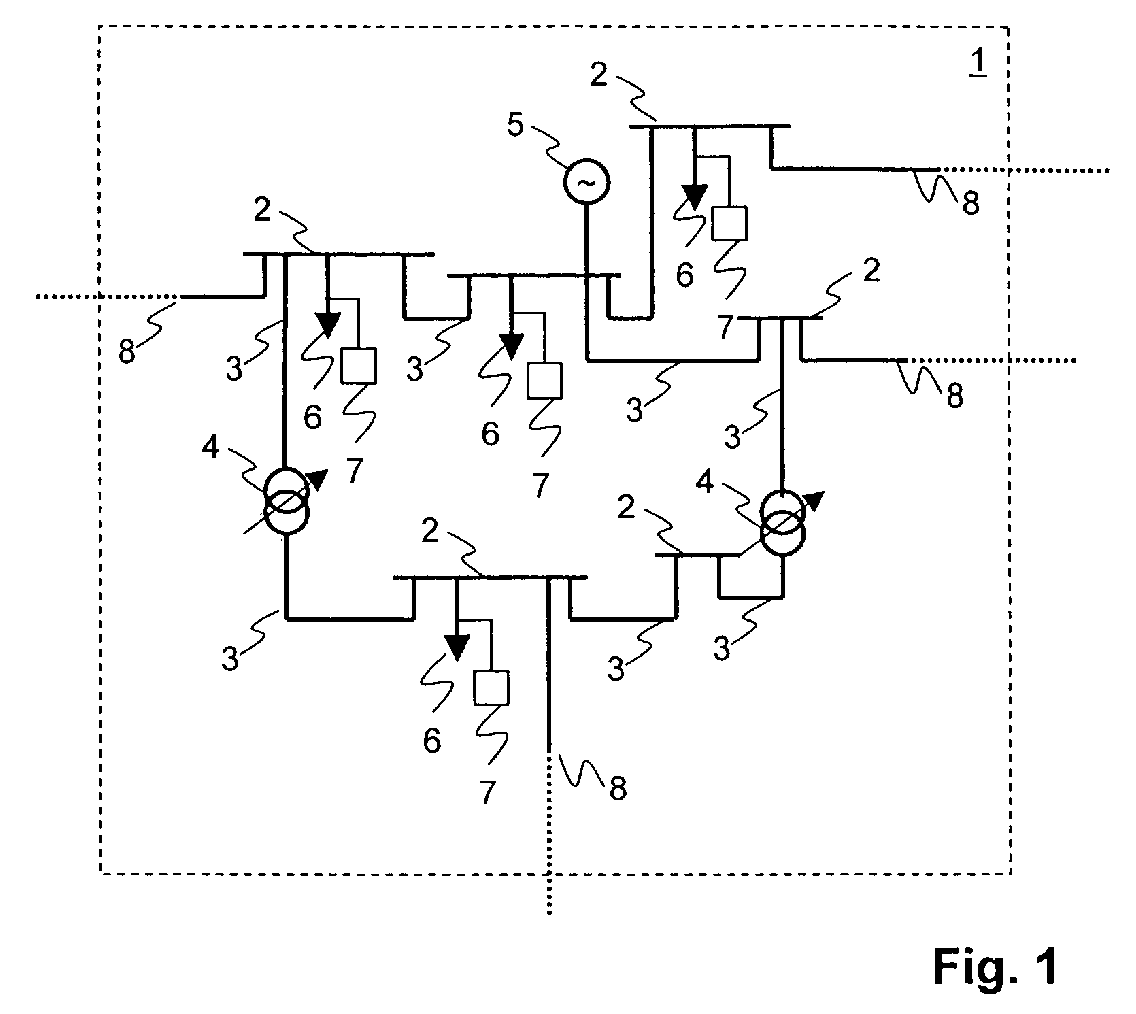
- FIG. 1 schematically shows a part 1 of an electric power network.
- Buses 2 are connected by lines 3 which may comprise under load tap changers (ULTC) 4.
- An under load tap changer is a transformer whose voltage ratio may be switched in discrete steps.
- generators 5 such as single generators or complete power plants and loads 6.
- Loads 6 are consumers of power or other networks, e.g. at a lower voltage level.
- Each load 6 is connected to the network by a load connection which is, for example a feeder leading to a power consumer.
- the feeder may lead to a high of medium voltage distribution network.
- At least one phasor measurement unit 7 is connected to a bus 2 or to a feeder.
- Interface lines 8 lead to neighboring networks.
- the phasor measurement unit 7 measures phasors of voltage at and current through an electric connection such as a feeder or line or busbar.
- the phasor data represents a phasor and may be a polar number, the absolute value of which corresponds to either the real magnitude or the RMS value of a quantity, and the phase argument to the phase angle at zero time.
- the phasor may be a complex number having real and imaginary parts or the phasor may use rectangular or exponential notation. Phasors may be used to represent quantities such as the voltage, current, power or energy associated with a phase conductor or an electronic circuit.
- conventional sensing devices used in power networks generally measure only scalar, average representations, such as the RMS value of a voltage, current etc.
- phasors from all three phases may be represented by a single common phasor.
- the phasor measurement units 7 are used for three reasons. First, the measurements are taken with short time intervals of approximately 20 to 100 milliseconds. This gives a view on the system with a high resolution over time. Second, the provided phasor information requires an installation of phasor measurement units 7 at only about each third or forth station or bus for an area that is to be observed. Third, synchronized time-triggered and time-stamped measurements from the entirety of phasor measurement units 7 together form a dynamic snapshot of the system state. The first reason is related to the parameter determination of the load parameter, the second and third reason are related to the dynamic observation of the critical area and the determination of the equilibrium of the system model.
- Figure 2 shows a time history over time t with typical values of voltage U and power flow P at a load connection after a contingency occurs.
- a contingency is an unexpected event such as, for example, a line 3 tripping, a generator 5 tripping, an extreme change in load or a feeder opening. While Figure 2 shows the effects of an unexpected voltage drop at a load connection, similar effects occur for voltage increases, and the invention is applicable as well.
- the voltage U and power P remain approximately constant, as shown by the trajectories Us(t) and Ps(t).
- an increase in generated power or a reduction of power consumption will cause the voltage U and power P to return to nominal values.
- the voltage U and with it the power P will further decrease, as shown by the trajectories Un(t) and Pn(t).
- Un(t) and Pn(t) Whether the situation is stable or unstable is a property of the entire network, not just of the load 6 itself. However, the dynamic behavior of each load 6 influences the network and its stability. It therefore is necessary to analyze the interplay between the network and all loads, as well as generators.
- load flow equations or power flow equations.
- load flow equations express the relation between the voltages at the connections of the elements and the power they consume or generate.
- Methods to solve such an equation system are well known as "load flow calculation” or “load flow analysis” and use, for example a Newton-Raphson algorithm.
- the power network comprises ULTCs 4
- their controlled behaviour is described by step functions that represent a voltage ratio as a function of one of the transformer voltages.
- the extended load flow analysis in this case incorporates a representation or model of the ULTCs behaviour, as shown in "Voltage Stability of Electric Power Systems", Vournas, C.; Van Cutsem, T., Kluwer Academic Publishers, Boston, 1998.
- the load flow analysis uses an optimization technique that determines a steady state solution that satisfies all equations including the ULTC equations,.
- Modeling of a generator 5 or power generating unit such as a power plant may be simplified to the point that a behaviour of a generator 5 is described only by the maximum reactive power that it is allowed to generate continuously, i.e. in a steady state. These values are known in advance from the operational diagram of the generator. The maximum influences the load flow calculation by giving a boundary condition on the space of solutions to the load flow problem.
- the voltage controller of generator 5 is represented by the static relationship between generator power output and generator voltage. This represents the steady state part of a voltage controller and excitation system of the generator model.
- the behavior of neighboring networks connected to the network under consideration by interface lines 8 is modeled by static or dynamic relationships such as constant power or current on the interface line, representation as constant impedance or as a Thevenin equivalent of the neighboring network.
- the resulting equation system contains the load flow equations, extended by steady state or static representations of all the elements of the power system which influence the stability.
- the solution of this equation system is a stable equilibrium and therefore a steady state solution of a complete dynamic representation of the power system. Therefore it is valid to determine the future equilibrium or steady-state solution with the load flow calculation with the embedded static models instead of executing a dynamic simulation over time.
- This solution of the extended set of equations is called extended load flow calculation.
- the load flow calculation requires a number of network, generator and load parameters. Some of these are constant, some may be determined prior to a contingency, but some remain unknown at the time the contingency occurs.
- the voltage/power characteristics of the loads 6 change slowly, that is with time constants in the range of hours. These characteristics can, in general, not be measured or identified as long as the power network is in its normal and nominal steady state, since unchanging values do not provide enough information.
- the contingency causes changes in voltage U and power P to each of the loads 6, it is possible to identify load parameters for each load 6 immediately after a contingency occurs.
- measurement data obtained in a transient phase between to and tc is used to identify the load parameters.
- a further aspect of the invention is that only load parameters relevant to a static or stationary behaviour of each load 6 are identified. Since these parameters change only slowly with respect to the seconds or minutes between the contingency at t0 and the manifestation of the instability at td, the parameters are used in a static load flow calculation to determine the stability of the network, i.e. of the part of the network under consideration. The stability can therefore be assessed long before an instability manifests itself visibly, as it does after td.
- FIG. 3 shows a flow diagram of the inventive method.
- step 31 voltages and currents at load connections are measured by phasor measurement units 7, each of which is associated to one load 6 whose behaviour is to be identified. From these measurements, steady state absolute voltages U 0 , steady state active power P 0 and steady state reactive power Q 0 are continuously updated. Network topology is updated from a known or measured state of switches and breakers. If no contingency is detected, execution continues in step 36, where a stability margin is computed in a known fashion. When a contingency is detected by known means, e.g. when a large and fast voltage change occurs at at least one load 6, execution proceeds to step 32. In step 32, a sequence of voltage and power values is measured at the load connections.
- step 33 Based on these measured values, in step 33, for each load 6 whose behaviour is to be identified, at least one parameter describing the stationary behaviour of the load is estimated.
- step 34 the extended load flow calculation is performed, using among others said load parameters.
- step 35 it is checked whether the extended load flow calculation has arrived at a solution. If it has, then in step 36 a stability margin is computed on the base of the found solution in a known fashion, taking also into account the steady-state models which are included in the extended load flow calculation. The stability margin is optionally communicated to an operator. If it has not, then in step 37 remedial actions such as shedding loads are taken in order to achieve stability. Other remedial actions are, for example reactive power increase, blocking of ULTC-tapping, control of FACTS-devices, Automatic Generation Control (AGC), Secondary Voltage Control, change of voltage set values of controllable devices or controlled islanding.
- AGC Automatic Generation Control
- the load model implicitly used in step 33 is a so-called Hill and Karlsson model, described in "Modelling and identification of nonlinear dynamic loads in power systems"; Hill, D. J. and Karlsson, D., IEEE Trans. on Power Systems, Vol. 9, No. 1, pp. 157- 163, 1994.
- U 0 and P 0 are a nominal voltage and nominal active power, respectively, as measured prior to the contingency. It is assumed that P 0 does not change stepwise and remains essentially unchanged for the purposes of the invention, i.e. during and after the transient phase caused by a contingency.
- P ⁇ and U ⁇ are time derivatives and are preferably determined as mean values of gradients determined from a series of measurement points.
- Voltage values considered in the context of the invention are absolute voltage values of voltage phasors representing a three-phase system. Parameters are a time constant T p and exponents ⁇ S and ⁇ t .
- ⁇ S Steady state behaviour is determined by ⁇ S .
- Typical values for ⁇ S can be expected to lie between approximately 0 and 2 for active power. If the same analysis is done for the reactive power part of the load, typical values of a corresponding exponent ⁇ S are 0 to 4.
- T p is typically between 20 and 300 seconds and ⁇ t between 0 and 5. Detailed measured values are given in the reference on the Hill and Karlsson Model cited above.
- Figure 4 shows time histories of voltage U and power P representing a step change in voltage followed by a trajectory according to Eq. (2).
- U ( t 0- ) and P L ( t 0- ) are the voltage and the power prior to the contingency occurring at time t 0 .
- a gradient of P L ( t ) determines the time constant T p .
- the desired value P L ( ⁇ ) can now be determined by solving equation (2) for P L ( ⁇ ) with the measured load P L ( t ) at the time t . This value can be updated over time.
- ⁇ S is determined by the following steps:
- U ( t 0+ ) is determined as a minimum of values obtained by filtering voltage measurements that are measured from immediately after the contingency has been detected for approximately 1 to 5 seconds. For example, a sliding window is moved over the measurements, for every window position, an average of values in the window is determined as a filtered value, and a minimum of filtered values is taken to be U ( t 0+ ).
- the load flow calculation uses
- the above method showed how to determine load characteristics for active power after a contingency. Characteristics describing reactive power consumption of the load are determined in the same fashion, replacing in all the measurements and equations mentioned above the active power P by reactive power Q . A variable ⁇ S corresponding to ⁇ S is then determined which determines the steady state relationship between voltage and reactive power.
- ⁇ S not just a single pair but a plurality of voltage and power measurements is used to estimate ⁇ S .
- a series of measurements of voltage U and power P as well as their derivatives are obtained.
- an over-determined set of nonlinear equations, i.e. several times Eq. (1) results, where each instance of Eq. (1) holds for a different measurement point.
- the set of equations can be solved for the parameters, in particular for ⁇ S .
- the voltage U is constant for the purpose of transforming Eq. (1) to the form of Eq. (5) is an approximation, and is only valid for small changes in the voltage U within the sliding window. Since the change in voltage U decreases after the contingency, the accuracy of the approximation increases from time t0 to tb.
- the measurements in the sliding window, made at times t1, t2, t3, ... tn define an over-determined linear system of equations which can be solved e.g. by the least squares approach. From x 2 , ⁇ S is immediately determined.
- measurement values providing good estimates of the steady state parameters are obtained starting at a time ta which lies from ca. 5 to 15 seconds after the time t0 at which the contingency occurs, since the approximation inherent in Eqs. (5) and (6) improves with time.
- the short-term transients of voltage and power in the first ca. 2 to 5 seconds after the contingency must have subsided before the sliding window can start to collect data.
- a typical length of the sliding window is between 3 and 10 seconds. Therefore the starting time plus the sliding window results in the above values of about 5 to 15 seconds after which the first results are available.
- ⁇ S should have been estimated, so that the remaining steps of the method can be executed and enough time remains for remedial actions.
- the extended load flow calculation can be started.
- the average of several following results from the sliding window can be taken. In a preferred embodiment of the invention, averages are taken over up to approximately 5 seconds. For a continuous supervision of the stability, an average of the last results is taken for continuous calculations of stability. In order to schedule and execute stabilizing actions as soon as possible, the first results available are preferably used.
- the method according to the invention comprises the steps of, after a contingency has been detected,
- the step a) of determining, for one load connected by a load connection to the electric power network, the at least one parameter describing the estimated steady state behaviour of the load comprises measuring a voltage and a power flow from phasor measurements at the load connection, where measurement intervals, i.e. the time between measurements are approximately 20 to 250 milliseconds.
- the load flow calculation is extended by the steady state behaviour of all elements of the power system. This means that the solution of the load flow calculation is the equilibrium or steady-state solution of the full dynamic system.
- a device for the prediction of the stability of an electric power network comprises means for determining, after a contingency has occurred and during a time interval in which the network is in a transient condition, for one load associated with the device, at least one parameter that describes an estimated steady state behaviour of the load.
- the device determines the parameter ⁇ S according to one of the first, second or third preferred embodiments of the invention described above.
- the device comprises
- Such an inventive device is preferably a phasor measurement unit 7 itself, or a device associated with a phasor measurement unit 7.
- the values of parameter ⁇ S obtained by a plurality of such devices are transmitted by each device to the remote device, for example to a central data processor, in which the load flow analysis and further steps of the inventive method are performed.
Abstract
Description
- The invention relates to the field of electric power transmission networks, and, more particularly, to a method, computer program product and device for the prediction of the stability of an electric power network as described in the preamble of
claims 1, 10 and 11, respectively. - An electric power transmission network comprises high-voltage tie lines and substations for transforming voltages and for switching connections between lines. Loads and power generating plants are connected to the network. An important issue when controlling power generation and load flow is to keep the network stable, i.e. to avoid voltage collapse and swings. Existing SCADA (Supervisory control and data acquisition) systems provide estimates about the stability of a network. However, such an estimate is based on the assumption that the network is in a steady state condition. Consequently, it is not valid if it is obtained during a transient condition, i.e. in the time after a fault or contingency has occurred and before the network is back in a seemingly steady state. It often happens that the network seems to be in a steady state after a contingency, however, an instability caused by the contingency develops unnoticed. The instability is detected by the SCADA system only when the network voltages are severely affected. At this point in time, remedial actions such as load shedding must be drastic, if complete collapse of the network is to be avoided. It therefore is desirable to obtain, after a contingency is detected, an early estimate of the future stability of a network, such that remedial actions can be executed before the effects of the instability become too large.
- US 5'638'297 shows a method of on-line transient stability assessment of an electrical power system. A computer model is used to simulate an effect of an artificially introduced study contingency. The simulation uses a step-by-step integration method and predicts future effects of the contingency on the network, in particular on network stability. However, the method requires a full model of dynamic behavior of the network and a significant computational effort for the simulation. The algorithm uses pre-calculations that are made before a given contingency occurs. If a contingency was not pre-calculated or if cascaded contingencies occur, the algorithm fails. If applied to voltage stability, the algorithm would fail as well for cascaded contingencies since an exhaustive pre-calculation of combinations of contingencies is not practicable.
- It is therefore an object of the invention to create a method and computer program product for the prediction of the stability of an electric power network of the type mentioned initially, which overcome the disadvantages mentioned above.
- These objects are achieved by a method, computer program product and device for the prediction of the stability of an electric power network according to the
claims 1, 10 and 11. - In the method for the prediction of the stability of an electric power network according to the invention, the method is executed after a contingency has occurred, and comprises the steps of
- a) during a time interval in which the network is in a transient condition, determining, for at least one load connected to the electric power network, at least one parameter describing an estimated steady state behaviour of the load,
- b) executing a load flow calculation for determining a steady state equilibrium of the electric power network, using the least one parameter describing the estimated steady state behaviour the at least one load,
- c) determining, if the load flow calculation indicates stability, i.e. if it has a solution, that a future stability of the electrical power network exists, or, if the load flow calculation indicates instability, i.e. if it does not have a solution, that a future stability of the electrical power network does not exist.
-
- The inventive method thus determines, during a transient state of the network, one or more parameters relevant to the network's future steady state or stationary behaviour. The future steady state equilibrium of the dynamic system is then determined without any need for a simulation over time. Modeling and computation effort is therefore reduced significantly, as compared to a dynamic simulation of network behaviour, but nevertheless the behaviour of the complete system around the equilibrium point is determined. Since calculations are necessary only after a contingency occurs, the algorithm is independent from any pre-calculations and is applicable to any contingency or combination of contingencies.
- In a preferred embodiment of the invention, the load flow calculation is a so-called extended load flow calculation that includes steady state behaviour of a variety of elements of the power system, in particular of under load tap changers and of power generators.
- The computer program product for the prediction of the stability of an electric power network according to the invention is loadable into an internal memory of a digital computer, and comprises computer program code means to make, when said computer program code means is loaded in the computer, the computer execute the method according to the invention. In a preferred embodiment of the invention, the computer program product comprises a computer readable medium, having the computer program code means recorded thereon.
- The device for the prediction of the stability of an electric power network after a contingency has occurred comprises
- a) means for storing values of voltage and power measurements made at the load,
- b) means for detecting an occurrence of a contingency,
- c) means for determining at least one parameter, where the parameter describes an estimated steady state behaviour of the load, from the stored voltage and power values and from measurement values that are obtained when the network is in a transient condition after the contingency has occurred.
-
- Further preferred embodiments are evident from the dependent patent claims.
- The subject matter of the invention will be explained in more detail in the following text with reference to preferred exemplary embodiments which are illustrated in the attached drawings, in which:
- Figure 1
- schematically shows part of an electrical power transmission network;
- Figure 2
- shows a time history with typical values of voltage and power flow at a load connection after a contingency occurs;
- Figure 3
- shows a flow diagram of the inventive method; and
- Figure 4
- shows a time history of voltage and power flow and its relation to parameters of a load model.
- The reference symbols used in the drawings, and their meanings, are listed in summary form in the list of reference symbols. In principle, identical parts are provided with the same reference symbols in the figures.
- Figure 1 schematically shows a
part 1 of an electric power network.Buses 2 are connected bylines 3 which may comprise under load tap changers (ULTC) 4. An under load tap changer is a transformer whose voltage ratio may be switched in discrete steps. Also connected tobuses 2 are generators 5 such as single generators or complete power plants andloads 6.Loads 6 are consumers of power or other networks, e.g. at a lower voltage level. Eachload 6 is connected to the network by a load connection which is, for example a feeder leading to a power consumer. When the section of electric power network under consideration is a high voltage transmission network, the feeder may lead to a high of medium voltage distribution network. At least onephasor measurement unit 7 is connected to abus 2 or to a feeder.Interface lines 8 lead to neighboring networks. - The
phasor measurement unit 7 measures phasors of voltage at and current through an electric connection such as a feeder or line or busbar. The phasor data represents a phasor and may be a polar number, the absolute value of which corresponds to either the real magnitude or the RMS value of a quantity, and the phase argument to the phase angle at zero time. Alternatively, the phasor may be a complex number having real and imaginary parts or the phasor may use rectangular or exponential notation. Phasors may be used to represent quantities such as the voltage, current, power or energy associated with a phase conductor or an electronic circuit. By contrast, conventional sensing devices used in power networks generally measure only scalar, average representations, such as the RMS value of a voltage, current etc. In a three-phase power system whose phases are in a balanced state, phasors from all three phases may be represented by a single common phasor. - The
phasor measurement units 7 are used for three reasons. First, the measurements are taken with short time intervals of approximately 20 to 100 milliseconds. This gives a view on the system with a high resolution over time. Second, the provided phasor information requires an installation ofphasor measurement units 7 at only about each third or forth station or bus for an area that is to be observed. Third, synchronized time-triggered and time-stamped measurements from the entirety ofphasor measurement units 7 together form a dynamic snapshot of the system state. The first reason is related to the parameter determination of the load parameter, the second and third reason are related to the dynamic observation of the critical area and the determination of the equilibrium of the system model. - Figure 2 shows a time history over time t with typical values of voltage U and power flow P at a load connection after a contingency occurs. A contingency is an unexpected event such as, for example, a
line 3 tripping, a generator 5 tripping, an extreme change in load or a feeder opening. While Figure 2 shows the effects of an unexpected voltage drop at a load connection, similar effects occur for voltage increases, and the invention is applicable as well. - At time t0, the contingency occurs, causing the voltage U to drop. Such unexpected voltage drops or increases typically are in the range of a few percent to 10% percent of a nominal voltage. The voltage drop causes the power flow P to the
load 6 to decrease as well. Due to the decrease in power P, local controllers of theload 6 try to draw more power in order to reach a nominal power consumption or operating point. This increase in power flow P in turn causes the voltage U to drop even more. At time tc the values for voltage U and power P have reached a seemingly steady state. However, only one of the two curves corresponds to a steady state while the other one corresponds to an unstable state, due to long term dynamic effects of the load, the ULTCs and the generators. "Long-term" in this context refers to time ranges of several seconds to several tens or hundreds of seconds. - If the state is stable, the voltage U and power P remain approximately constant, as shown by the trajectories Us(t) and Ps(t). At a later time, an increase in generated power or a reduction of power consumption will cause the voltage U and power P to return to nominal values. In the unstable case, after a time td the voltage U and with it the power P will further decrease, as shown by the trajectories Un(t) and Pn(t). Whether the situation is stable or unstable is a property of the entire network, not just of the
load 6 itself. However, the dynamic behavior of eachload 6 influences the network and its stability. It therefore is necessary to analyze the interplay between the network and all loads, as well as generators. This interplay between the loads, the generators and the network is described with a set of static equations called load flow equations or power flow equations. These equations express the relation between the voltages at the connections of the elements and the power they consume or generate. Methods to solve such an equation system are well known as "load flow calculation" or "load flow analysis" and use, for example a Newton-Raphson algorithm. - In order to determine the stability of the network, said equations are combined and the resulting set of equations is solved using load flow analysis. If the power network comprises ULTCs 4, their controlled behaviour is described by step functions that represent a voltage ratio as a function of one of the transformer voltages. The extended load flow analysis in this case incorporates a representation or model of the ULTCs behaviour, as shown in "Voltage Stability of Electric Power Systems", Vournas, C.; Van Cutsem, T., Kluwer Academic Publishers, Boston, 1998. The load flow analysis uses an optimization technique that determines a steady state solution that satisfies all equations including the ULTC equations,.
- Modeling of a generator 5 or power generating unit such as a power plant may be simplified to the point that a behaviour of a generator 5 is described only by the maximum reactive power that it is allowed to generate continuously, i.e. in a steady state. These values are known in advance from the operational diagram of the generator. The maximum influences the load flow calculation by giving a boundary condition on the space of solutions to the load flow problem. In a preferred embodiment of the invention, the voltage controller of generator 5 is represented by the static relationship between generator power output and generator voltage. This represents the steady state part of a voltage controller and excitation system of the generator model.
- The behavior of neighboring networks connected to the network under consideration by
interface lines 8 is modeled by static or dynamic relationships such as constant power or current on the interface line, representation as constant impedance or as a Thevenin equivalent of the neighboring network. - The resulting equation system contains the load flow equations, extended by steady state or static representations of all the elements of the power system which influence the stability. The solution of this equation system is a stable equilibrium and therefore a steady state solution of a complete dynamic representation of the power system. Therefore it is valid to determine the future equilibrium or steady-state solution with the load flow calculation with the embedded static models instead of executing a dynamic simulation over time. This solution of the extended set of equations is called extended load flow calculation.
- If the load flow calculation reaches a solution, then the network is stable, if not, then the network is unstable. The load flow calculation requires a number of network, generator and load parameters. Some of these are constant, some may be determined prior to a contingency, but some remain unknown at the time the contingency occurs. In particular, the voltage/power characteristics of the
loads 6 change slowly, that is with time constants in the range of hours. These characteristics can, in general, not be measured or identified as long as the power network is in its normal and nominal steady state, since unchanging values do not provide enough information. However, since the contingency causes changes in voltage U and power P to each of theloads 6, it is possible to identify load parameters for eachload 6 immediately after a contingency occurs. - According to the invention, measurement data obtained in a transient phase between to and tc is used to identify the load parameters. A further aspect of the invention is that only load parameters relevant to a static or stationary behaviour of each
load 6 are identified. Since these parameters change only slowly with respect to the seconds or minutes between the contingency at t0 and the manifestation of the instability at td, the parameters are used in a static load flow calculation to determine the stability of the network, i.e. of the part of the network under consideration. The stability can therefore be assessed long before an instability manifests itself visibly, as it does after td. - Figure 3 shows a flow diagram of the inventive method. In
step 31, voltages and currents at load connections are measured byphasor measurement units 7, each of which is associated to oneload 6 whose behaviour is to be identified. From these measurements, steady state absolute voltages U 0, steady state active power P 0 and steady state reactive power Q 0 are continuously updated. Network topology is updated from a known or measured state of switches and breakers. If no contingency is detected, execution continues instep 36, where a stability margin is computed in a known fashion. When a contingency is detected by known means, e.g. when a large and fast voltage change occurs at at least oneload 6, execution proceeds to step 32. Instep 32, a sequence of voltage and power values is measured at the load connections. Based on these measured values, instep 33, for eachload 6 whose behaviour is to be identified, at least one parameter describing the stationary behaviour of the load is estimated. Instep 34, the extended load flow calculation is performed, using among others said load parameters. Instep 35 it is checked whether the extended load flow calculation has arrived at a solution. If it has, then in step 36 a stability margin is computed on the base of the found solution in a known fashion, taking also into account the steady-state models which are included in the extended load flow calculation. The stability margin is optionally communicated to an operator. If it has not, then instep 37 remedial actions such as shedding loads are taken in order to achieve stability. Other remedial actions are, for example reactive power increase, blocking of ULTC-tapping, control of FACTS-devices, Automatic Generation Control (AGC), Secondary Voltage Control, change of voltage set values of controllable devices or controlled islanding. - In a preferred embodiment of the invention, the load model implicitly used in
step 33 is a so-called Hill and Karlsson model, described in "Modelling and identification of nonlinear dynamic loads in power systems"; Hill, D. J. and Karlsson, D., IEEE Trans. on Power Systems, Vol. 9, No. 1, pp. 157- 163, 1994. The model describes the behaviour of a load as seen from a feeder of a high voltage system by a differential equation - The equation gives the dynamic relation between the voltage U at and the power P through a connection to the load. U 0 and P 0 are a nominal voltage and nominal active power, respectively, as measured prior to the contingency. It is assumed that P 0 does not change stepwise and remains essentially unchanged for the purposes of the invention, i.e. during and after the transient phase caused by a contingency. P ˙ and U ˙ are time derivatives and are preferably determined as mean values of gradients determined from a series of measurement points. Voltage values considered in the context of the invention are absolute voltage values of voltage phasors representing a three-phase system. Parameters are a time constant Tp and exponents α S and α t . These parameters are to be determined, since they change during a day and over the seasons. Steady state behaviour is determined by α S . Typical values for α S can be expected to lie between approximately 0 and 2 for active power. If the same analysis is done for the reactive power part of the load, typical values of a corresponding exponent βS are 0 to 4. Tp is typically between 20 and 300 seconds and αt between 0 and 5. Detailed measured values are given in the reference on the Hill and Karlsson Model cited above.
- In a first preferred embodiment of the invention, the parameters are determined as follows: For a step change in voltage, the solution of Eq. (1) is, for t>t0, given by
- Figure 4 shows time histories of voltage U and power P representing a step change in voltage followed by a trajectory according to Eq. (2). U(t 0-) and PL (t 0-) are the voltage and the power prior to the contingency occurring at time t 0. A gradient of PL (t) determines the time constant Tp . The desired value PL (∞) can now be determined by solving equation (2) for PL (∞) with the measured load PL (t) at the time t. This value can be updated over time.
- U(t 0+) is the voltage after the contingency. From the steady state part of (1), i.e. by setting P ˙ and U ˙ to zero, it follows that
- Since PL (t 0 - ) = P 0 and U(t 0-) = U 0, α S is determined by Eq. (3). From Eq. (1) it can be seen that αS influences a stationary part of the expression, whereas α t is associated with a dynamic part and becomes irrelevant when derivatives over time are zero.
- In summary, in the first preferred embodiment of the invention, αS is determined by the following steps:
- 1. From the power PL (t 0+) immediately after the contingency and a sequence of Power measurements PL (t), determine the time constant Tp .and PL (∞) from Eq. (2).
- 2. From PL (∞), a measurement of U(t 0+) and power and voltage values made prior to the contingency, determine αS from Eq. (3).
-
- For practical purposes, U(t 0+) is determined as a minimum of values obtained by filtering voltage measurements that are measured from immediately after the contingency has been detected for approximately 1 to 5 seconds. For example, a sliding window is moved over the measurements, for every window position, an average of values in the window is determined as a filtered value, and a minimum of filtered values is taken to be U(t 0+).
- The load flow calculation uses
- either the constant value PL (∞) for the load flow, which gives approximate results, or
- the expression
- The above method showed how to determine load characteristics for active power after a contingency. Characteristics describing reactive power consumption of the load are determined in the same fashion, replacing in all the measurements and equations mentioned above the active power P by reactive power Q. A variable β S corresponding to α S is then determined which determines the steady state relationship between voltage and reactive power.
- In a second preferred embodiment of the invention, not just a single pair but a plurality of voltage and power measurements is used to estimate α S . In a sliding window of measurements, a series of measurements of voltage U and power P as well as their derivatives are obtained. For more than three measurement points, an over-determined set of nonlinear equations, i.e. several times Eq. (1), results, where each instance of Eq. (1) holds for a different measurement point. The set of equations can be solved for the parameters, in particular for α S .
- In a third preferred embodiment of the invention, Eq. (1) is rewritten as
x U is a mean of voltages measured in the sliding measurement window. Assuming the voltage U to be constant for the purpose of transforming Eq. (1) to the form of Eq. (5) is an approximation, and is only valid for small changes in the voltage U within the sliding window. Since the change in voltage U decreases after the contingency, the accuracy of the approximation increases from time t0 to tb. The measurements in the sliding window, made at times t1, t2, t3, ... tn define an over-determined linear system of equationswhich can be solved e.g. by the least squares approach. From x 2, α S is immediately determined.
- In the preferred embodiments of the invention, measurement values providing good estimates of the steady state parameters are obtained starting at a time ta which lies from ca. 5 to 15 seconds after the time t0 at which the contingency occurs, since the approximation inherent in Eqs. (5) and (6) improves with time. The short-term transients of voltage and power in the first ca. 2 to 5 seconds after the contingency must have subsided before the sliding window can start to collect data. A typical length of the sliding window is between 3 and 10 seconds. Therefore the starting time plus the sliding window results in the above values of about 5 to 15 seconds after which the first results are available.
- After this time, αS should have been estimated, so that the remaining steps of the method can be executed and enough time remains for remedial actions.
- Beginning with the results from the first sliding window, the extended load flow calculation can be started. In order to increase robustness at the expense of speed, the average of several following results from the sliding window can be taken. In a preferred embodiment of the invention, averages are taken over up to approximately 5 seconds. For a continuous supervision of the stability, an average of the last results is taken for continuous calculations of stability. In order to schedule and execute stabilizing actions as soon as possible, the first results available are preferably used.
- In summary, the method according to the invention comprises the steps of, after a contingency has been detected,
- a) During a time interval in which the network is in a transient condition, determining for at least one load connected to the electric power network, at least one parameter αS that describes an estimated steady state, i.e. stationary behaviour of the load.
- b) Executing a load flow calculation for the electric power network using the least one parameter α S that describes the estimated steady state behaviour at the at least one load. The load flow calculation is also based on values that characterize the state of the network prior to the contingency, such as power and voltage at the at least one load.
- c) Determining, if the load flow calculation indicates stability, i.e. if it has a solution, that a future stability of the electrical power network exists, or, if the load flow calculation indicates instability, i.e. if it does not have a solution, that a future stability of the electrical power network does not exist.
-
- In a preferred embodiment of the invention, the step a) of determining, for one load connected by a load connection to the electric power network, the at least one parameter describing the estimated steady state behaviour of the load, comprises measuring a voltage and a power flow from phasor measurements at the load connection, where measurement intervals, i.e. the time between measurements are approximately 20 to 250 milliseconds.
- In a further preferred embodiment of the invention, the load flow calculation is extended by the steady state behaviour of all elements of the power system. This means that the solution of the load flow calculation is the equilibrium or steady-state solution of the full dynamic system.
- A device for the prediction of the stability of an electric power network according to the invention comprises means for determining, after a contingency has occurred and during a time interval in which the network is in a transient condition, for one load associated with the device, at least one parameter that describes an estimated steady state behaviour of the load. In a preferred embodiment of the invention, the device determines the parameter α S according to one of the first, second or third preferred embodiments of the invention described above.
- The device comprises
- means for storing values of voltage and power measurements made at the load,
- means for locally detecting an occurrence of a contingency, preferably by detecting a voltage drop of, for example, 2%.,
- means for determining the at least one parameter α S , where the parameter describes an estimated steady state behaviour of the load, from the stored voltage and power values and from measurement values that are obtained when the network is in a transient condition after the contingency has occurred, and, in a preferred embodiment,
- means for transmitting the parameter α S to a remote device.
- Such an inventive device is preferably a
phasor measurement unit 7 itself, or a device associated with aphasor measurement unit 7. The values of parameter α S obtained by a plurality of such devices are transmitted by each device to the remote device, for example to a central data processor, in which the load flow analysis and further steps of the inventive method are performed. -
- 1
- section of electric power network
- 2
- bus
- 3
- line
- 4
- ULTC (under load tap changer)
- 5
- generator
- 6
- load
- 7
- phasor measurement unit
- 8
- interface line
- 31
- "conting?", check for contingency
- 32
- "meas", perform measurements
- 33
- "parest", estimate parameters
- 34
- "pflo", perform load flow calculation
- 35
- "sol?", check existence of solution
- 36
- "marg", compute power margin
- 37
- "stabl!", perform stabilizing actions
Claims (11)
- A method for the prediction of the stability of an electric power network, where said method is executed after a contingency has occurred, characterized in that the method comprises the steps ofa) during a time interval in which the network is in a transient condition, determining (33) for at least one load connected to the electric power network, at least one parameter that describes an estimated steady state behaviour of the load,b) executing a load flow calculation (34) for determining a steady state equilibrium of the electric power network, using the least one parameter,c) determining (35), if the load flow calculation has a solution, that a future stability of the electrical power network exists, or, if the load flow calculation does not have a solution, that a future stability of the electrical power network does not exist.
- Method according to claim 1, characterized in that the method comprises the step (36) of determining a power margin of the electric power network, using the at least one parameter describing the estimated steady state behaviour of the at least one load.
- Method according to claim 1, characterized in that the method comprises the step (37) of taking a remedial action in order to prevent a predicted instability from occurring.
- Method according to claim 1, characterized in that determining (33), for one load connected by a load connection to the electric power network, the at least one parameter describing the estimated steady state behaviour of the load, comprises measuring a voltage and a power flow at the load connection, where measurement intervals are approximately 20 to 250 milliseconds.
- Method according to claim 1, characterized in that a time interval in which the at least one parameter describing the estimated steady state behaviour of the at least one load is determined begins at the time when a contingency is detected and has a length of approximately 1 to 20 seconds.
- Method according to claim 1, characterized in that the at least one load is modeled by the equation
- U
- is a voltage at and P a power flow through a connection to the load,
- U ˙ and P ˙
- are their derivatives over time,
- U 0 and P 0
- are a nominal voltage and nominal active power, respectively,
- Tp
- is a time constant,
and where α S is the parameter describing the estimated steady state behaviour.
- Method according to claim 1, characterized in that the load flow is an extended load flow calculation that incorporates at least one of models for under load tap changers (4) and models that describe the behaviour of at least one power generating unit (5).
- Method according to claim 7, characterized in that at least one of the power generating units (5) is described by the maximum steady state reactive power that said power generating unit (5) may provide in a steady state.
- Method according to claim 1, characterized in that the load flow calculation incorporates network parameters that are obtained prior to the occurrence of the contingency, and where said network parameters are a nominal voltage U 0 and a nominal active power P 0 measured prior to the contingency.
- Computer program product for the prediction of the stability of an electric power network according to the invention that is loadable into an internal memory of a digital computer, and comprises computer program code means to make, when said computer program code means is loaded in the computer, the computer execute the method according to one of the preceding claims.
- A device for the prediction of the stability of an electric power network, after a contingency has occurred, characterized in that the device comprisesa) means for storing values of voltage and power measurements made at the load,b) means for detecting an occurrence of a contingency,c) means for determining at least one parameter, where the parameter describes an estimated steady state behaviour of the load, from the stored voltage and power values and from measurement values that are obtained when the network is in a transient condition after the contingency has occurred.
Priority Applications (7)
| Application Number | Priority Date | Filing Date | Title |
|---|---|---|---|
| AT01112354T ATE504969T1 (en) | 2001-05-21 | 2001-05-21 | STABILITY PREDICTION FOR ELECTRICAL ENERGY NETWORK |
| DE60144367T DE60144367D1 (en) | 2001-05-21 | 2001-05-21 | Stability prediction for electric power grid |
| ES01112354T ES2364451T3 (en) | 2001-05-21 | 2001-05-21 | STABILITY FORECAST FOR AN ELECTRICAL POWER NETWORK. |
| EP01112354A EP1261096B1 (en) | 2001-05-21 | 2001-05-21 | Stability prediction for an electric power network |
| US10/144,069 US7096175B2 (en) | 2001-05-21 | 2002-05-14 | Stability prediction for an electric power network |
| NO20022349A NO325888B1 (en) | 2001-05-21 | 2002-05-16 | Stability prediction for an electric power grid |
| JP2002142499A JP2003052126A (en) | 2001-05-21 | 2002-05-17 | Stability prediction of power network |
Applications Claiming Priority (1)
| Application Number | Priority Date | Filing Date | Title |
|---|---|---|---|
| EP01112354A EP1261096B1 (en) | 2001-05-21 | 2001-05-21 | Stability prediction for an electric power network |
Publications (2)
| Publication Number | Publication Date |
|---|---|
| EP1261096A1 true EP1261096A1 (en) | 2002-11-27 |
| EP1261096B1 EP1261096B1 (en) | 2011-04-06 |
Family
ID=8177490
Family Applications (1)
| Application Number | Title | Priority Date | Filing Date |
|---|---|---|---|
| EP01112354A Revoked EP1261096B1 (en) | 2001-05-21 | 2001-05-21 | Stability prediction for an electric power network |
Country Status (7)
| Country | Link |
|---|---|
| US (1) | US7096175B2 (en) |
| EP (1) | EP1261096B1 (en) |
| JP (1) | JP2003052126A (en) |
| AT (1) | ATE504969T1 (en) |
| DE (1) | DE60144367D1 (en) |
| ES (1) | ES2364451T3 (en) |
| NO (1) | NO325888B1 (en) |
Cited By (33)
| Publication number | Priority date | Publication date | Assignee | Title |
|---|---|---|---|---|
| WO2006068614A1 (en) * | 2004-12-22 | 2006-06-29 | Abb Ab | A method and a device for controlled reclosing of a circuit breaker |
| EP1780619A1 (en) * | 2005-10-31 | 2007-05-02 | Abb Research Ltd. | Initializing an estimation of dynamic model parameters |
| WO2008006116A2 (en) | 2006-07-07 | 2008-01-10 | Edsa Micro Corporation | Systems and methods for real-time dynamic simulation of uninterruptible power supply solutions and their control logic systems |
| CN101789598A (en) * | 2010-03-05 | 2010-07-28 | 湖北省电力试验研究院 | Power system load modelling method |
| CN101478157B (en) * | 2008-10-13 | 2011-05-04 | 宁波电业局 | Automatic electricity generation control system and load prediction automatic integrated optimization method |
| CN102074955A (en) * | 2011-01-20 | 2011-05-25 | 中国电力科学研究院 | Method based on knowledge discovery technology for stability assessment and control of electric system |
| US8036872B2 (en) | 2006-03-10 | 2011-10-11 | Edsa Micro Corporation | Systems and methods for performing automatic real-time harmonics analyses for use in real-time power analytics of an electrical power distribution system |
| US8126685B2 (en) | 2006-04-12 | 2012-02-28 | Edsa Micro Corporation | Automatic real-time optimization and intelligent control of electrical power distribution and transmission systems |
| US8131401B2 (en) | 2006-07-19 | 2012-03-06 | Power Analytics Corporation | Real-time stability indexing for intelligent energy monitoring and management of electrical power network system |
| US8155943B2 (en) | 2007-10-12 | 2012-04-10 | Power Analytics Corporation | Systems and methods for automatically converting CAD drawing files into intelligent objects with database connectivity for the design, analysis, and simulation of electrical power systems |
| US8155908B2 (en) | 2006-02-14 | 2012-04-10 | Power Analytics Corporation | Systems and methods for real-time system monitoring and predictive analysis |
| US8165723B2 (en) | 2006-03-10 | 2012-04-24 | Power Analytics Corporation | Real-time system for verification and monitoring of protective device settings within an electrical power distribution network and automatic correction of deviances found |
| US8170856B2 (en) | 2006-04-12 | 2012-05-01 | Power Analytics Corporation | Systems and methods for real-time advanced visualization for predicting the health, reliability and performance of an electrical power system |
| US8180622B2 (en) | 2006-10-24 | 2012-05-15 | Power Analytics Corporation | Systems and methods for a real-time synchronized electrical power system simulator for “what-if” analysis and prediction over electrical power networks |
| US8229722B2 (en) | 2007-05-16 | 2012-07-24 | Power Analytics Corporation | Electrical power system modeling, design, analysis, and reporting via a client-server application framework |
| CN102684187A (en) * | 2012-04-24 | 2012-09-19 | 南京南瑞集团公司 | Power grid static stability analysis method on basis of WAMS and online simulation data |
| EA017830B1 (en) * | 2012-07-20 | 2013-03-29 | Открытое Акционерное Общество "Системный Оператор Единой Энергетической Системы" | Method of a choice of control actions for putting the postemergency operation conditions of a power system in admissable boundaries on a condition of an aperiodic static stability |
| EA018097B1 (en) * | 2012-06-26 | 2013-05-30 | Открытое Акционерное Общество "Системный Оператор Единой Энергетической Системы" | Method for preventing collapse of voltage in a power system |
| US8577661B2 (en) | 2006-04-12 | 2013-11-05 | Power Analytics Corporation | Systems and methods for alarm filtering and management within a real-time data acquisition and monitoring environment |
| CN103595053A (en) * | 2013-11-19 | 2014-02-19 | 云南电网公司电网规划研究中心 | Optimization generator tripping method of power grid stability strategy on basis of capacity proximity principle |
| US8688429B2 (en) | 2006-03-10 | 2014-04-01 | Power Analytics Corporation | System for comparing real-time data and modeling engine data to predict arc flash events |
| US8775934B2 (en) | 2006-07-19 | 2014-07-08 | Power Analytics Corporation | Systems and methods for creation of a schematic user interface for monitoring and predicting the real-time health, reliability and performance of an electrical power system |
| US8868398B2 (en) | 2006-06-29 | 2014-10-21 | Power Analytics Corporation | Method for predicting arc flash energy and PPE category within a real-time monitoring system |
| US8959006B2 (en) | 2006-03-10 | 2015-02-17 | Power Analytics Corporation | Systems and methods for automatic real-time capacity assessment for use in real-time power analytics of an electrical power distribution system |
| RU2548025C2 (en) * | 2009-09-15 | 2015-04-10 | Сименс Акциенгезелльшафт | Power network monitoring |
| US9031824B2 (en) | 2006-07-19 | 2015-05-12 | Power Analytics Corporation | Real-time predictive systems for intelligent energy monitoring and management of electrical power networks |
| US9092593B2 (en) | 2007-09-25 | 2015-07-28 | Power Analytics Corporation | Systems and methods for intuitive modeling of complex networks in a digital environment |
| CN108092304A (en) * | 2017-12-06 | 2018-05-29 | 昆明理工大学 | Power system transient stability method of discrimination based on phase path Yu relative kinetic energy change rate |
| US10281507B2 (en) | 2014-11-21 | 2019-05-07 | Kohler Co. | Generator sizing |
| WO2019157171A1 (en) * | 2018-02-08 | 2019-08-15 | Quanta Technology, Llc | Predicting voltage stability of a power system post-contingency |
| US10867087B2 (en) | 2006-02-14 | 2020-12-15 | Wavetech Global, Inc. | Systems and methods for real-time DC microgrid power analytics for mission-critical power systems |
| US10962999B2 (en) | 2009-10-01 | 2021-03-30 | Wavetech Global Inc. | Microgrid model based automated real time simulation for market based electric power system optimization |
| US11113434B2 (en) | 2006-02-14 | 2021-09-07 | Power Analytics Corporation | Method for predicting arc flash energy and PPE category within a real-time monitoring system |
Families Citing this family (50)
| Publication number | Priority date | Publication date | Assignee | Title |
|---|---|---|---|---|
| CA2400580A1 (en) * | 2002-09-03 | 2004-03-03 | Sureshchandra B. Patel | Systems of advanced super decoupled load-flow computation for electrical power system |
| US7860702B1 (en) * | 2002-09-18 | 2010-12-28 | Peter B. Evans | Assessing distributed energy resources for the energynet |
| EP1408595B1 (en) * | 2002-10-10 | 2017-06-14 | ABB Research Ltd. | Determining parameters of an equivalent circuit representing a transmission section of an electrical network |
| US20040158417A1 (en) * | 2002-11-06 | 2004-08-12 | Bonet Antonio Trias | System and method for monitoring and managing electrical power transmission and distribution networks |
| US7519506B2 (en) * | 2002-11-06 | 2009-04-14 | Antonio Trias | System and method for monitoring and managing electrical power transmission and distribution networks |
| US7321810B2 (en) * | 2003-05-13 | 2008-01-22 | Siemens Power Transmission & Distribution, Inc. | Method of dynamic economic dispatch |
| US7454270B2 (en) * | 2003-05-13 | 2008-11-18 | Siemens Power Transmission & Distribution, Inc. | Dynamic economic dispatch for the management of a power distribution system |
| KR100576511B1 (en) * | 2004-05-11 | 2006-05-03 | 한국전기연구원 | System and method for calculating real-time voltage stability risk index in power system using time series data |
| KR100794245B1 (en) * | 2006-08-22 | 2008-01-11 | 한국전기연구원 | An intelligent monitoring system of the reactive power limit of generator using machine model parameters and method the same |
| US7816927B2 (en) * | 2007-07-27 | 2010-10-19 | British Columbia Hydro And Power Authority | Method and system for real time identification of voltage stability via identification of weakest lines and buses contributing to power system collapse |
| CA2700973C (en) * | 2007-09-28 | 2014-05-13 | Schweitzer Engineering Laboratories, Inc. | Systems and methods for power swing and out-of-step detection using time stamped data |
| US8326589B2 (en) * | 2008-03-26 | 2012-12-04 | The Tokyo Electric Power Company, Incorporated | Stable equilibrium point (SEP) calculation apparatus of power system |
| JP5358668B2 (en) * | 2008-03-26 | 2013-12-04 | 東京電力株式会社 | Power system stable equilibrium point calculation device |
| SG10201606766QA (en) | 2008-05-09 | 2016-10-28 | Accenture Global Services Ltd | Method and system for managing a power grid |
| US20110004446A1 (en) * | 2008-12-15 | 2011-01-06 | Accenture Global Services Gmbh | Intelligent network |
| CN101291061B (en) * | 2008-05-16 | 2010-04-21 | 南京南瑞继保电气有限公司 | Status estimating method for dynamic process of electrical power system |
| US8103466B2 (en) | 2009-01-14 | 2012-01-24 | Accenture Global Services Limited | Distribution system analysis using meter data |
| US8103467B2 (en) * | 2009-01-14 | 2012-01-24 | Accenture Global Services Limited | Determination of distribution transformer voltages based on metered loads |
| US8554385B2 (en) * | 2009-09-11 | 2013-10-08 | Schweitzer Engineering Laboratories Inc. | Systems and methods for monitoring and controlling electrical system stability |
| US8706309B2 (en) * | 2010-04-10 | 2014-04-22 | Schweitzer Engineering Laboratories Inc | Systems and method for obtaining a load model and related parameters based on load dynamics |
| CN103038606B (en) | 2010-07-30 | 2016-03-30 | 埃森哲环球服务有限公司 | Intelligent core engine |
| US8648499B2 (en) | 2011-01-27 | 2014-02-11 | General Electric Company | Systems, methods, and apparatus for accelerating volt/VAR load flow optimization |
| US8816531B2 (en) | 2011-01-27 | 2014-08-26 | General Electric Company | Systems, methods, and apparatus for integrated volt/VAR control in power distribution networks |
| CN102354981B (en) * | 2011-09-30 | 2013-07-03 | 河海大学 | Distributed computation based voltage stability assessment method of sub-networks in interconnected power network |
| CN102508061B (en) * | 2011-10-22 | 2014-02-12 | 东北电力大学 | Power shortage estimation method based on wide area phasor measurement system |
| BR112014014601B1 (en) * | 2011-12-16 | 2020-05-05 | Siemens Ag | method to generate a signal that indicates an oscillation of an electrical variable in an electricity supply network |
| CN102623988B (en) * | 2012-03-27 | 2014-01-29 | 清华大学 | Automatic generating method for day-ahead plan power flow in power grid |
| US8773829B2 (en) | 2012-10-31 | 2014-07-08 | General Electric Company | Method and system for power swing detection in a generator |
| US9563722B2 (en) * | 2012-11-13 | 2017-02-07 | Gridquant, Inc. | Sigma algebraic approximants as a diagnostic tool in power networks |
| US9819227B2 (en) * | 2013-02-26 | 2017-11-14 | Schweitzer Engineering Laboratories, Inc. | State trajectory prediction in an electric power delivery system |
| EP2806280A1 (en) * | 2013-05-21 | 2014-11-26 | ABB Research Ltd. | Detecting electrical islands using wide-area measurements |
| US10333312B2 (en) | 2013-06-26 | 2019-06-25 | Schweitzer Engineering Laboratories, Inc. | Distributed control in electric power delivery systems |
| GB201314611D0 (en) * | 2013-08-15 | 2013-10-02 | Univ The Of Birmingham | Power system control |
| US20150160670A1 (en) * | 2013-12-09 | 2015-06-11 | Georgia Tech Research Corporation | Methods and systems for using distributed energy resources in an electric network |
| US9823637B2 (en) * | 2014-09-05 | 2017-11-21 | Southern States, Llc | Fault detection and isolation using a common reference clock |
| CN104393594B (en) * | 2014-11-28 | 2017-05-03 | 南车株洲电力机车研究所有限公司 | Analytical calculation method for medium voltage network flow of urban rail transit |
| CN104901328B (en) * | 2015-05-21 | 2017-08-22 | 北京四方继保自动化股份有限公司 | Based on the soft straight control model automatic identifying method of the multiterminal under complex control network |
| USD810104S1 (en) | 2015-11-16 | 2018-02-13 | Kohler, Co. | Display screen with graphical user interface |
| USD811423S1 (en) | 2015-11-16 | 2018-02-27 | Kohler, Co. | Display screen with graphical user interface |
| RU2611259C1 (en) * | 2016-01-29 | 2017-02-21 | Открытое Акционерное Общество "Системный Оператор Единой Энергетической Системы" | Automated device for determining limit modes of electrical systems |
| US10027119B2 (en) | 2016-05-28 | 2018-07-17 | PXiSE Energy Solutions, LLC | Decoupling synchrophasor based control system for multiple distributed energy resources |
| US10615604B2 (en) | 2016-05-28 | 2020-04-07 | PXiSE Energy Solutions, LLC | Decoupling synchrophasor based control system for distributed energy resources |
| US10452032B1 (en) | 2016-09-08 | 2019-10-22 | PXiSE Energy Solutions, LLC | Optimizing power contribution of distributed energy resources for real time power demand scheduling |
| JP6713937B2 (en) * | 2017-01-30 | 2020-06-24 | 株式会社日立製作所 | System operation decision support device and method |
| US10599175B1 (en) | 2017-02-28 | 2020-03-24 | PXiSE Energy Solutions, LLC | Time synchronized frequency and voltage regulation of electric power balancing areas |
| US10990072B2 (en) | 2017-11-28 | 2021-04-27 | PXiSE Energy Solutions, LLC | Maintaining power grid stability using predicted data |
| CN108667007B (en) * | 2018-04-16 | 2019-12-13 | 清华大学 | Voltage stability margin calculation method considering constraint of electric-gas coupling system |
| CN110460059B (en) * | 2019-07-26 | 2023-02-03 | 国网山东省电力公司泰安供电公司 | Power flow calculation method for power system |
| US11056912B1 (en) | 2021-01-25 | 2021-07-06 | PXiSE Energy Solutions, LLC | Power system optimization using hierarchical clusters |
| CN116646941A (en) * | 2023-04-07 | 2023-08-25 | 上海交通大学 | Method for dynamically adjusting stable voltage through on-load tap-changer |
Citations (1)
| Publication number | Priority date | Publication date | Assignee | Title |
|---|---|---|---|---|
| US5566085A (en) * | 1992-09-24 | 1996-10-15 | Hydro-Quebec | Stability transfer limit calculation in a power transmission network |
Family Cites Families (4)
| Publication number | Priority date | Publication date | Assignee | Title |
|---|---|---|---|---|
| US5638297A (en) * | 1994-07-15 | 1997-06-10 | British Columbia Hydro And Power Authority | Method of on-line transient stability assessment of electrical power systems |
| US5625751A (en) * | 1994-08-30 | 1997-04-29 | Electric Power Research Institute | Neural network for contingency ranking dynamic security indices for use under fault conditions in a power distribution system |
| US5719787A (en) * | 1996-05-15 | 1998-02-17 | Cornell Research Foundation, Inc. | Method for on-line dynamic contingency screening of electric power systems |
| US6202041B1 (en) * | 1998-04-29 | 2001-03-13 | Hong Kong Polytechnic University | Electrical power network modelling method |
-
2001
- 2001-05-21 ES ES01112354T patent/ES2364451T3/en not_active Expired - Lifetime
- 2001-05-21 DE DE60144367T patent/DE60144367D1/en not_active Expired - Lifetime
- 2001-05-21 AT AT01112354T patent/ATE504969T1/en not_active IP Right Cessation
- 2001-05-21 EP EP01112354A patent/EP1261096B1/en not_active Revoked
-
2002
- 2002-05-14 US US10/144,069 patent/US7096175B2/en not_active Expired - Fee Related
- 2002-05-16 NO NO20022349A patent/NO325888B1/en not_active IP Right Cessation
- 2002-05-17 JP JP2002142499A patent/JP2003052126A/en active Pending
Patent Citations (1)
| Publication number | Priority date | Publication date | Assignee | Title |
|---|---|---|---|---|
| US5566085A (en) * | 1992-09-24 | 1996-10-15 | Hydro-Quebec | Stability transfer limit calculation in a power transmission network |
Non-Patent Citations (5)
| Title |
|---|
| CHIEW-YANN CHIOU: "DEVELOPMENT OF A MICRO-PROCESSOR-BASED TRANSIENT DATA RECORDING SYSTEM FOR LOAD BEHAVIOR ANALYSIS", IEEE TRANSACTIONS ON POWER SYSTEMS, IEEE INC. NEW YORK, US, vol. 8, no. 1, 1 February 1993 (1993-02-01), pages 16 - 22, XP000385227, ISSN: 0885-8950 * |
| LIU C-W ET AL: "Application of synchronised phasor measurements to real-time transient stability prediction", IEE PROCEEDINGS: GENERATION, TRANSMISSION AND DISTRIBUTION, INSTITUTION OF ELECTRICAL ENGINEERS, GB, vol. 142, no. 4, 1 July 1995 (1995-07-01), pages 355 - 60, XP006004157, ISSN: 1350-2360 * |
| LIU: "Application of synchronized phasor measurements to real-time transient stability prediction", IEEE PROCEEDINGS, vol. 142, no. 4, 1 July 1995 (1995-07-01), pages 355 - 360 |
| QUINTANA V H ET AL: "Voltage stability as affected by discrete changes in the topology of power networks", IEE PROCEEDINGS: GENERATION, TRANSMISSION AND DISTRIBUTION, INSTITUTION OF ELECTRICAL ENGINEERS, GB, vol. 141, no. 4, 1 July 1994 (1994-07-01), pages 346 - 52, XP006001833, ISSN: 1350-2360 * |
| VU ET AL: "Use of local measurements to estimate voltage-stability margin", POWER INDUSTRY COMPUTER APPLICATIONS., 1997. 20TH INTERNATIONAL CONFERENCE ON COLUMBUS, OH, USA 11-16 MAY 1997, NEW YORK, NY, USA,IEEE, US, 11 May 1997 (1997-05-11), pages 318 - 323, XP010227937, ISBN: 0-7803-3713-1 * |
Cited By (49)
| Publication number | Priority date | Publication date | Assignee | Title |
|---|---|---|---|---|
| EP1829184A1 (en) * | 2004-12-22 | 2007-09-05 | Abb Ab | A method and a device for controlled reclosing of a circuit breaker |
| US8183718B2 (en) | 2004-12-22 | 2012-05-22 | Abb Ab | Method and device for controlled reclosing of a circuit breaker |
| EP1829184A4 (en) * | 2004-12-22 | 2013-09-04 | Abb Ab | A method and a device for controlled reclosing of a circuit breaker |
| CN101095270B (en) * | 2004-12-22 | 2012-09-12 | Abb公司 | A method and a device for controlled reclosing of a circuit breaker |
| WO2006068614A1 (en) * | 2004-12-22 | 2006-06-29 | Abb Ab | A method and a device for controlled reclosing of a circuit breaker |
| US7912589B2 (en) | 2005-10-31 | 2011-03-22 | Abb Research Ltd | Initializing an estimation of dynamic model parameters |
| EP1780619A1 (en) * | 2005-10-31 | 2007-05-02 | Abb Research Ltd. | Initializing an estimation of dynamic model parameters |
| WO2007051334A1 (en) * | 2005-10-31 | 2007-05-10 | Abb Research Ltd | Initializing an estimation of dynamic model parameters |
| US11113434B2 (en) | 2006-02-14 | 2021-09-07 | Power Analytics Corporation | Method for predicting arc flash energy and PPE category within a real-time monitoring system |
| US10867087B2 (en) | 2006-02-14 | 2020-12-15 | Wavetech Global, Inc. | Systems and methods for real-time DC microgrid power analytics for mission-critical power systems |
| US8155908B2 (en) | 2006-02-14 | 2012-04-10 | Power Analytics Corporation | Systems and methods for real-time system monitoring and predictive analysis |
| US8959006B2 (en) | 2006-03-10 | 2015-02-17 | Power Analytics Corporation | Systems and methods for automatic real-time capacity assessment for use in real-time power analytics of an electrical power distribution system |
| US8036872B2 (en) | 2006-03-10 | 2011-10-11 | Edsa Micro Corporation | Systems and methods for performing automatic real-time harmonics analyses for use in real-time power analytics of an electrical power distribution system |
| US8165723B2 (en) | 2006-03-10 | 2012-04-24 | Power Analytics Corporation | Real-time system for verification and monitoring of protective device settings within an electrical power distribution network and automatic correction of deviances found |
| US8688429B2 (en) | 2006-03-10 | 2014-04-01 | Power Analytics Corporation | System for comparing real-time data and modeling engine data to predict arc flash events |
| US8577661B2 (en) | 2006-04-12 | 2013-11-05 | Power Analytics Corporation | Systems and methods for alarm filtering and management within a real-time data acquisition and monitoring environment |
| US8126685B2 (en) | 2006-04-12 | 2012-02-28 | Edsa Micro Corporation | Automatic real-time optimization and intelligent control of electrical power distribution and transmission systems |
| US8170856B2 (en) | 2006-04-12 | 2012-05-01 | Power Analytics Corporation | Systems and methods for real-time advanced visualization for predicting the health, reliability and performance of an electrical power system |
| US9111057B2 (en) | 2006-06-29 | 2015-08-18 | Power Analytics Corporation | Method for predicting arc flash energy and PPE category within a real-time monitoring system |
| US8868398B2 (en) | 2006-06-29 | 2014-10-21 | Power Analytics Corporation | Method for predicting arc flash energy and PPE category within a real-time monitoring system |
| EP2038782A4 (en) * | 2006-07-07 | 2010-11-17 | Edsa Micro Corp | Systems and methods for real-time dynamic simulation of uninterruptible power supply solutions and their control logic systems |
| EP2038782A2 (en) * | 2006-07-07 | 2009-03-25 | EDSA Micro Corporation | Systems and methods for real-time dynamic simulation of uninterruptible power supply solutions and their control logic systems |
| WO2008006116A2 (en) | 2006-07-07 | 2008-01-10 | Edsa Micro Corporation | Systems and methods for real-time dynamic simulation of uninterruptible power supply solutions and their control logic systems |
| US8131401B2 (en) | 2006-07-19 | 2012-03-06 | Power Analytics Corporation | Real-time stability indexing for intelligent energy monitoring and management of electrical power network system |
| US9557723B2 (en) | 2006-07-19 | 2017-01-31 | Power Analytics Corporation | Real-time predictive systems for intelligent energy monitoring and management of electrical power networks |
| US9031824B2 (en) | 2006-07-19 | 2015-05-12 | Power Analytics Corporation | Real-time predictive systems for intelligent energy monitoring and management of electrical power networks |
| US8775934B2 (en) | 2006-07-19 | 2014-07-08 | Power Analytics Corporation | Systems and methods for creation of a schematic user interface for monitoring and predicting the real-time health, reliability and performance of an electrical power system |
| US8180622B2 (en) | 2006-10-24 | 2012-05-15 | Power Analytics Corporation | Systems and methods for a real-time synchronized electrical power system simulator for “what-if” analysis and prediction over electrical power networks |
| US8229722B2 (en) | 2007-05-16 | 2012-07-24 | Power Analytics Corporation | Electrical power system modeling, design, analysis, and reporting via a client-server application framework |
| US9092593B2 (en) | 2007-09-25 | 2015-07-28 | Power Analytics Corporation | Systems and methods for intuitive modeling of complex networks in a digital environment |
| US8155943B2 (en) | 2007-10-12 | 2012-04-10 | Power Analytics Corporation | Systems and methods for automatically converting CAD drawing files into intelligent objects with database connectivity for the design, analysis, and simulation of electrical power systems |
| CN101478157B (en) * | 2008-10-13 | 2011-05-04 | 宁波电业局 | Automatic electricity generation control system and load prediction automatic integrated optimization method |
| RU2548025C2 (en) * | 2009-09-15 | 2015-04-10 | Сименс Акциенгезелльшафт | Power network monitoring |
| US10962999B2 (en) | 2009-10-01 | 2021-03-30 | Wavetech Global Inc. | Microgrid model based automated real time simulation for market based electric power system optimization |
| CN101789598A (en) * | 2010-03-05 | 2010-07-28 | 湖北省电力试验研究院 | Power system load modelling method |
| CN102074955B (en) * | 2011-01-20 | 2015-06-10 | 中国电力科学研究院 | Method based on knowledge discovery technology for stability assessment and control of electric system |
| CN102074955A (en) * | 2011-01-20 | 2011-05-25 | 中国电力科学研究院 | Method based on knowledge discovery technology for stability assessment and control of electric system |
| CN102684187A (en) * | 2012-04-24 | 2012-09-19 | 南京南瑞集团公司 | Power grid static stability analysis method on basis of WAMS and online simulation data |
| CN102684187B (en) * | 2012-04-24 | 2015-08-05 | 南京南瑞集团公司 | A kind of electrical network static stability analysis method based on WAMS and in-circuit emulation data |
| EA018097B1 (en) * | 2012-06-26 | 2013-05-30 | Открытое Акционерное Общество "Системный Оператор Единой Энергетической Системы" | Method for preventing collapse of voltage in a power system |
| RU2508590C1 (en) * | 2012-06-26 | 2014-02-27 | Открытое Акционерное Общество "Системный Оператор Единой Энергетической Системы" | Method for prevention of voltage collapse in power system |
| EA017830B1 (en) * | 2012-07-20 | 2013-03-29 | Открытое Акционерное Общество "Системный Оператор Единой Энергетической Системы" | Method of a choice of control actions for putting the postemergency operation conditions of a power system in admissable boundaries on a condition of an aperiodic static stability |
| CN103595053B (en) * | 2013-11-19 | 2016-01-20 | 云南电网公司电网规划研究中心 | Machine method is cut in power grid stability strategy proximity optimization by measure |
| CN103595053A (en) * | 2013-11-19 | 2014-02-19 | 云南电网公司电网规划研究中心 | Optimization generator tripping method of power grid stability strategy on basis of capacity proximity principle |
| US10281507B2 (en) | 2014-11-21 | 2019-05-07 | Kohler Co. | Generator sizing |
| CN108092304A (en) * | 2017-12-06 | 2018-05-29 | 昆明理工大学 | Power system transient stability method of discrimination based on phase path Yu relative kinetic energy change rate |
| CN108092304B (en) * | 2017-12-06 | 2021-03-02 | 昆明理工大学 | Electric power system transient stability discrimination method based on phase track and relative kinetic energy change rate |
| WO2019157171A1 (en) * | 2018-02-08 | 2019-08-15 | Quanta Technology, Llc | Predicting voltage stability of a power system post-contingency |
| US11316345B2 (en) | 2018-02-08 | 2022-04-26 | Quanta Associates, L.P. | Predictive voltage stability of a power system post-contingency |
Also Published As
| Publication number | Publication date |
|---|---|
| EP1261096B1 (en) | 2011-04-06 |
| NO20022349L (en) | 2002-11-22 |
| NO20022349D0 (en) | 2002-05-16 |
| DE60144367D1 (en) | 2011-05-19 |
| US20030040846A1 (en) | 2003-02-27 |
| ES2364451T3 (en) | 2011-09-02 |
| ATE504969T1 (en) | 2011-04-15 |
| NO325888B1 (en) | 2008-08-11 |
| JP2003052126A (en) | 2003-02-21 |
| US7096175B2 (en) | 2006-08-22 |
Similar Documents
| Publication | Publication Date | Title |
|---|---|---|
| EP1261096B1 (en) | Stability prediction for an electric power network | |
| US11588333B2 (en) | Microgrid power flow monitoring and control | |
| US7107162B2 (en) | Determining an operational limit of a power transmission line | |
| EP1381132B1 (en) | Power network parameter estimation | |
| CN100431232C (en) | Estimating of power transmission net state | |
| US9450409B2 (en) | Converter station power set point analysis system and method | |
| RU2625913C2 (en) | Analysis of distribution system using electricity data | |
| WO2017182918A1 (en) | Method of determining mutual voltage sensitivity coefficients between a plurality of measuring nodes of an electric power network | |
| US20140371929A1 (en) | Source Impedance Estimation | |
| WO2000077908A1 (en) | An application and method for voltage instability predictor (vip) | |
| CN111937264B (en) | Method and apparatus for protection in a multi-terminal power transmission system | |
| CA2898657A1 (en) | State trajectory prediction in an electric power delivery system | |
| EP2770600A2 (en) | Method and system for determining power consumption of loads | |
| Momesso et al. | Adaptive directional overcurrent protection considering stability constraint | |
| US20020123849A1 (en) | Method and device for assessing the stability of an electric power transmission network | |
| Rehtanz et al. | A new wide area protection system | |
| Nakmali et al. | A new hybrid approach to thevenin equivalent estimation for voltage stability monitoring | |
| Shukla et al. | A hierarchical decentralized coordinated voltage instability detection scheme for SVC | |
| Alzahawi et al. | A special protection scheme for voltage stability prevention | |
| Cardet | Analysis on voltage stability indices | |
| Mostafa et al. | Neural network based overcurrent voltage controlled protection system in large electrical networks | |
| Gong | Development of an improved on-line voltage stability index using synchronized phasor measurement | |
| Solås | A wide area load shedding scheme to prevent voltage instability | |
| BR102021026191A2 (en) | ADAPTIVE OVERCURRENT PROTECTION METHOD FOR ELECTRIC POWER DISTRIBUTION SYSTEMS | |
| Doig Cardet | Analysis on voltage stability indices |
Legal Events
| Date | Code | Title | Description |
|---|---|---|---|
| PUAI | Public reference made under article 153(3) epc to a published international application that has entered the european phase |
Free format text: ORIGINAL CODE: 0009012 |
|
| AK | Designated contracting states |
Kind code of ref document: A1 Designated state(s): AT BE CH CY DE DK ES FI FR GB GR IE IT LI LU MC NL PT SE TR |
|
| AX | Request for extension of the european patent |
Free format text: AL;LT;LV;MK;RO;SI |
|
| 17P | Request for examination filed |
Effective date: 20030414 |
|
| AKX | Designation fees paid |
Designated state(s): AT BE CH CY DE DK ES FI FR GB GR IE IT LI LU MC NL PT SE TR |
|
| 17Q | First examination report despatched |
Effective date: 20070511 |
|
| GRAP | Despatch of communication of intention to grant a patent |
Free format text: ORIGINAL CODE: EPIDOSNIGR1 |
|
| GRAS | Grant fee paid |
Free format text: ORIGINAL CODE: EPIDOSNIGR3 |
|
| GRAA | (expected) grant |
Free format text: ORIGINAL CODE: 0009210 |
|
| AK | Designated contracting states |
Kind code of ref document: B1 Designated state(s): AT BE CH CY DE DK ES FI FR GB GR IE IT LI LU MC NL PT SE TR |
|
| REG | Reference to a national code |
Ref country code: GB Ref legal event code: FG4D |
|
| REG | Reference to a national code |
Ref country code: CH Ref legal event code: EP |
|
| REG | Reference to a national code |
Ref country code: IE Ref legal event code: FG4D |
|
| REF | Corresponds to: |
Ref document number: 60144367 Country of ref document: DE Date of ref document: 20110519 Kind code of ref document: P |
|
| REG | Reference to a national code |
Ref country code: DE Ref legal event code: R096 Ref document number: 60144367 Country of ref document: DE Effective date: 20110519 |
|
| REG | Reference to a national code |
Ref country code: NL Ref legal event code: VDEP Effective date: 20110406 |
|
| REG | Reference to a national code |
Ref country code: ES Ref legal event code: FG2A Ref document number: 2364451 Country of ref document: ES Kind code of ref document: T3 Effective date: 20110902 |
|
| PG25 | Lapsed in a contracting state [announced via postgrant information from national office to epo] |
Ref country code: PT Free format text: LAPSE BECAUSE OF FAILURE TO SUBMIT A TRANSLATION OF THE DESCRIPTION OR TO PAY THE FEE WITHIN THE PRESCRIBED TIME-LIMIT Effective date: 20110808 Ref country code: SE Free format text: LAPSE BECAUSE OF FAILURE TO SUBMIT A TRANSLATION OF THE DESCRIPTION OR TO PAY THE FEE WITHIN THE PRESCRIBED TIME-LIMIT Effective date: 20110406 |
|
| PG25 | Lapsed in a contracting state [announced via postgrant information from national office to epo] |
Ref country code: FI Free format text: LAPSE BECAUSE OF FAILURE TO SUBMIT A TRANSLATION OF THE DESCRIPTION OR TO PAY THE FEE WITHIN THE PRESCRIBED TIME-LIMIT Effective date: 20110406 Ref country code: GR Free format text: LAPSE BECAUSE OF FAILURE TO SUBMIT A TRANSLATION OF THE DESCRIPTION OR TO PAY THE FEE WITHIN THE PRESCRIBED TIME-LIMIT Effective date: 20110707 Ref country code: CY Free format text: LAPSE BECAUSE OF FAILURE TO SUBMIT A TRANSLATION OF THE DESCRIPTION OR TO PAY THE FEE WITHIN THE PRESCRIBED TIME-LIMIT Effective date: 20110406 Ref country code: AT Free format text: LAPSE BECAUSE OF FAILURE TO SUBMIT A TRANSLATION OF THE DESCRIPTION OR TO PAY THE FEE WITHIN THE PRESCRIBED TIME-LIMIT Effective date: 20110406 Ref country code: BE Free format text: LAPSE BECAUSE OF FAILURE TO SUBMIT A TRANSLATION OF THE DESCRIPTION OR TO PAY THE FEE WITHIN THE PRESCRIBED TIME-LIMIT Effective date: 20110406 |
|
| PG25 | Lapsed in a contracting state [announced via postgrant information from national office to epo] |
Ref country code: NL Free format text: LAPSE BECAUSE OF FAILURE TO SUBMIT A TRANSLATION OF THE DESCRIPTION OR TO PAY THE FEE WITHIN THE PRESCRIBED TIME-LIMIT Effective date: 20110406 Ref country code: MC Free format text: LAPSE BECAUSE OF NON-PAYMENT OF DUE FEES Effective date: 20110531 |
|
| REG | Reference to a national code |
Ref country code: CH Ref legal event code: PL |
|
| PLBI | Opposition filed |
Free format text: ORIGINAL CODE: 0009260 |
|
| PG25 | Lapsed in a contracting state [announced via postgrant information from national office to epo] |
Ref country code: CH Free format text: LAPSE BECAUSE OF NON-PAYMENT OF DUE FEES Effective date: 20110531 Ref country code: LI Free format text: LAPSE BECAUSE OF NON-PAYMENT OF DUE FEES Effective date: 20110531 |
|
| PLAX | Notice of opposition and request to file observation + time limit sent |
Free format text: ORIGINAL CODE: EPIDOSNOBS2 |
|
| 26 | Opposition filed |
Opponent name: SIEMENS AKTIENGESELLSCHAFT Effective date: 20120106 |
|
| REG | Reference to a national code |
Ref country code: IE Ref legal event code: MM4A |
|
| REG | Reference to a national code |
Ref country code: DE Ref legal event code: R026 Ref document number: 60144367 Country of ref document: DE Effective date: 20120106 |
|
| PG25 | Lapsed in a contracting state [announced via postgrant information from national office to epo] |
Ref country code: IE Free format text: LAPSE BECAUSE OF NON-PAYMENT OF DUE FEES Effective date: 20110521 |
|
| PLAF | Information modified related to communication of a notice of opposition and request to file observations + time limit |
Free format text: ORIGINAL CODE: EPIDOSCOBS2 |
|
| PLBB | Reply of patent proprietor to notice(s) of opposition received |
Free format text: ORIGINAL CODE: EPIDOSNOBS3 |
|
| PG25 | Lapsed in a contracting state [announced via postgrant information from national office to epo] |
Ref country code: LU Free format text: LAPSE BECAUSE OF NON-PAYMENT OF DUE FEES Effective date: 20110521 |
|
| PG25 | Lapsed in a contracting state [announced via postgrant information from national office to epo] |
Ref country code: TR Free format text: LAPSE BECAUSE OF FAILURE TO SUBMIT A TRANSLATION OF THE DESCRIPTION OR TO PAY THE FEE WITHIN THE PRESCRIBED TIME-LIMIT Effective date: 20110406 |
|
| REG | Reference to a national code |
Ref country code: FR Ref legal event code: PLFP Year of fee payment: 15 |
|
| PGFP | Annual fee paid to national office [announced via postgrant information from national office to epo] |
Ref country code: DE Payment date: 20150521 Year of fee payment: 15 Ref country code: ES Payment date: 20150527 Year of fee payment: 15 Ref country code: GB Payment date: 20150521 Year of fee payment: 15 |
|
| PGFP | Annual fee paid to national office [announced via postgrant information from national office to epo] |
Ref country code: IT Payment date: 20150516 Year of fee payment: 15 Ref country code: FR Payment date: 20150521 Year of fee payment: 15 |
|
| RDAF | Communication despatched that patent is revoked |
Free format text: ORIGINAL CODE: EPIDOSNREV1 |
|
| REG | Reference to a national code |
Ref country code: DE Ref legal event code: R064 Ref document number: 60144367 Country of ref document: DE Ref country code: DE Ref legal event code: R103 Ref document number: 60144367 Country of ref document: DE |
|
| RDAG | Patent revoked |
Free format text: ORIGINAL CODE: 0009271 |
|
| STAA | Information on the status of an ep patent application or granted ep patent |
Free format text: STATUS: PATENT REVOKED |
|
| 27W | Patent revoked |
Effective date: 20150925 |
|
| GBPR | Gb: patent revoked under art. 102 of the ep convention designating the uk as contracting state |
Effective date: 20150925 |