EP1260397A2 - A control strategy for a hybrid vehicle while traveling in reverse - Google Patents
A control strategy for a hybrid vehicle while traveling in reverse Download PDFInfo
- Publication number
- EP1260397A2 EP1260397A2 EP02253322A EP02253322A EP1260397A2 EP 1260397 A2 EP1260397 A2 EP 1260397A2 EP 02253322 A EP02253322 A EP 02253322A EP 02253322 A EP02253322 A EP 02253322A EP 1260397 A2 EP1260397 A2 EP 1260397A2
- Authority
- EP
- European Patent Office
- Prior art keywords
- generator motor
- torque request
- engine
- new
- motor torque
- Prior art date
- Legal status (The legal status is an assumption and is not a legal conclusion. Google has not performed a legal analysis and makes no representation as to the accuracy of the status listed.)
- Granted
Links
Images

Classifications
-
- B—PERFORMING OPERATIONS; TRANSPORTING
- B60—VEHICLES IN GENERAL
- B60W—CONJOINT CONTROL OF VEHICLE SUB-UNITS OF DIFFERENT TYPE OR DIFFERENT FUNCTION; CONTROL SYSTEMS SPECIALLY ADAPTED FOR HYBRID VEHICLES; ROAD VEHICLE DRIVE CONTROL SYSTEMS FOR PURPOSES NOT RELATED TO THE CONTROL OF A PARTICULAR SUB-UNIT
- B60W20/00—Control systems specially adapted for hybrid vehicles
- B60W20/10—Controlling the power contribution of each of the prime movers to meet required power demand
-
- B—PERFORMING OPERATIONS; TRANSPORTING
- B60—VEHICLES IN GENERAL
- B60K—ARRANGEMENT OR MOUNTING OF PROPULSION UNITS OR OF TRANSMISSIONS IN VEHICLES; ARRANGEMENT OR MOUNTING OF PLURAL DIVERSE PRIME-MOVERS IN VEHICLES; AUXILIARY DRIVES FOR VEHICLES; INSTRUMENTATION OR DASHBOARDS FOR VEHICLES; ARRANGEMENTS IN CONNECTION WITH COOLING, AIR INTAKE, GAS EXHAUST OR FUEL SUPPLY OF PROPULSION UNITS IN VEHICLES
- B60K6/00—Arrangement or mounting of plural diverse prime-movers for mutual or common propulsion, e.g. hybrid propulsion systems comprising electric motors and internal combustion engines ; Control systems therefor, i.e. systems controlling two or more prime movers, or controlling one of these prime movers and any of the transmission, drive or drive units Informative references: mechanical gearings with secondary electric drive F16H3/72; arrangements for handling mechanical energy structurally associated with the dynamo-electric machine H02K7/00; machines comprising structurally interrelated motor and generator parts H02K51/00; dynamo-electric machines not otherwise provided for in H02K see H02K99/00
- B60K6/20—Arrangement or mounting of plural diverse prime-movers for mutual or common propulsion, e.g. hybrid propulsion systems comprising electric motors and internal combustion engines ; Control systems therefor, i.e. systems controlling two or more prime movers, or controlling one of these prime movers and any of the transmission, drive or drive units Informative references: mechanical gearings with secondary electric drive F16H3/72; arrangements for handling mechanical energy structurally associated with the dynamo-electric machine H02K7/00; machines comprising structurally interrelated motor and generator parts H02K51/00; dynamo-electric machines not otherwise provided for in H02K see H02K99/00 the prime-movers consisting of electric motors and internal combustion engines, e.g. HEVs
- B60K6/42—Arrangement or mounting of plural diverse prime-movers for mutual or common propulsion, e.g. hybrid propulsion systems comprising electric motors and internal combustion engines ; Control systems therefor, i.e. systems controlling two or more prime movers, or controlling one of these prime movers and any of the transmission, drive or drive units Informative references: mechanical gearings with secondary electric drive F16H3/72; arrangements for handling mechanical energy structurally associated with the dynamo-electric machine H02K7/00; machines comprising structurally interrelated motor and generator parts H02K51/00; dynamo-electric machines not otherwise provided for in H02K see H02K99/00 the prime-movers consisting of electric motors and internal combustion engines, e.g. HEVs characterised by the architecture of the hybrid electric vehicle
- B60K6/44—Series-parallel type
- B60K6/445—Differential gearing distribution type
-
- B—PERFORMING OPERATIONS; TRANSPORTING
- B60—VEHICLES IN GENERAL
- B60L—PROPULSION OF ELECTRICALLY-PROPELLED VEHICLES; SUPPLYING ELECTRIC POWER FOR AUXILIARY EQUIPMENT OF ELECTRICALLY-PROPELLED VEHICLES; ELECTRODYNAMIC BRAKE SYSTEMS FOR VEHICLES IN GENERAL; MAGNETIC SUSPENSION OR LEVITATION FOR VEHICLES; MONITORING OPERATING VARIABLES OF ELECTRICALLY-PROPELLED VEHICLES; ELECTRIC SAFETY DEVICES FOR ELECTRICALLY-PROPELLED VEHICLES
- B60L15/00—Methods, circuits, or devices for controlling the traction-motor speed of electrically-propelled vehicles
- B60L15/20—Methods, circuits, or devices for controlling the traction-motor speed of electrically-propelled vehicles for control of the vehicle or its driving motor to achieve a desired performance, e.g. speed, torque, programmed variation of speed
- B60L15/2063—Methods, circuits, or devices for controlling the traction-motor speed of electrically-propelled vehicles for control of the vehicle or its driving motor to achieve a desired performance, e.g. speed, torque, programmed variation of speed for creeping
-
- B—PERFORMING OPERATIONS; TRANSPORTING
- B60—VEHICLES IN GENERAL
- B60L—PROPULSION OF ELECTRICALLY-PROPELLED VEHICLES; SUPPLYING ELECTRIC POWER FOR AUXILIARY EQUIPMENT OF ELECTRICALLY-PROPELLED VEHICLES; ELECTRODYNAMIC BRAKE SYSTEMS FOR VEHICLES IN GENERAL; MAGNETIC SUSPENSION OR LEVITATION FOR VEHICLES; MONITORING OPERATING VARIABLES OF ELECTRICALLY-PROPELLED VEHICLES; ELECTRIC SAFETY DEVICES FOR ELECTRICALLY-PROPELLED VEHICLES
- B60L50/00—Electric propulsion with power supplied within the vehicle
- B60L50/50—Electric propulsion with power supplied within the vehicle using propulsion power supplied by batteries or fuel cells
- B60L50/60—Electric propulsion with power supplied within the vehicle using propulsion power supplied by batteries or fuel cells using power supplied by batteries
- B60L50/61—Electric propulsion with power supplied within the vehicle using propulsion power supplied by batteries or fuel cells using power supplied by batteries by batteries charged by engine-driven generators, e.g. series hybrid electric vehicles
-
- B—PERFORMING OPERATIONS; TRANSPORTING
- B60—VEHICLES IN GENERAL
- B60W—CONJOINT CONTROL OF VEHICLE SUB-UNITS OF DIFFERENT TYPE OR DIFFERENT FUNCTION; CONTROL SYSTEMS SPECIALLY ADAPTED FOR HYBRID VEHICLES; ROAD VEHICLE DRIVE CONTROL SYSTEMS FOR PURPOSES NOT RELATED TO THE CONTROL OF A PARTICULAR SUB-UNIT
- B60W10/00—Conjoint control of vehicle sub-units of different type or different function
- B60W10/04—Conjoint control of vehicle sub-units of different type or different function including control of propulsion units
- B60W10/06—Conjoint control of vehicle sub-units of different type or different function including control of propulsion units including control of combustion engines
-
- B—PERFORMING OPERATIONS; TRANSPORTING
- B60—VEHICLES IN GENERAL
- B60W—CONJOINT CONTROL OF VEHICLE SUB-UNITS OF DIFFERENT TYPE OR DIFFERENT FUNCTION; CONTROL SYSTEMS SPECIALLY ADAPTED FOR HYBRID VEHICLES; ROAD VEHICLE DRIVE CONTROL SYSTEMS FOR PURPOSES NOT RELATED TO THE CONTROL OF A PARTICULAR SUB-UNIT
- B60W10/00—Conjoint control of vehicle sub-units of different type or different function
- B60W10/04—Conjoint control of vehicle sub-units of different type or different function including control of propulsion units
- B60W10/08—Conjoint control of vehicle sub-units of different type or different function including control of propulsion units including control of electric propulsion units, e.g. motors or generators
-
- B—PERFORMING OPERATIONS; TRANSPORTING
- B60—VEHICLES IN GENERAL
- B60W—CONJOINT CONTROL OF VEHICLE SUB-UNITS OF DIFFERENT TYPE OR DIFFERENT FUNCTION; CONTROL SYSTEMS SPECIALLY ADAPTED FOR HYBRID VEHICLES; ROAD VEHICLE DRIVE CONTROL SYSTEMS FOR PURPOSES NOT RELATED TO THE CONTROL OF A PARTICULAR SUB-UNIT
- B60W10/00—Conjoint control of vehicle sub-units of different type or different function
- B60W10/24—Conjoint control of vehicle sub-units of different type or different function including control of energy storage means
- B60W10/26—Conjoint control of vehicle sub-units of different type or different function including control of energy storage means for electrical energy, e.g. batteries or capacitors
-
- B—PERFORMING OPERATIONS; TRANSPORTING
- B60—VEHICLES IN GENERAL
- B60K—ARRANGEMENT OR MOUNTING OF PROPULSION UNITS OR OF TRANSMISSIONS IN VEHICLES; ARRANGEMENT OR MOUNTING OF PLURAL DIVERSE PRIME-MOVERS IN VEHICLES; AUXILIARY DRIVES FOR VEHICLES; INSTRUMENTATION OR DASHBOARDS FOR VEHICLES; ARRANGEMENTS IN CONNECTION WITH COOLING, AIR INTAKE, GAS EXHAUST OR FUEL SUPPLY OF PROPULSION UNITS IN VEHICLES
- B60K1/00—Arrangement or mounting of electrical propulsion units
- B60K1/02—Arrangement or mounting of electrical propulsion units comprising more than one electric motor
-
- B—PERFORMING OPERATIONS; TRANSPORTING
- B60—VEHICLES IN GENERAL
- B60L—PROPULSION OF ELECTRICALLY-PROPELLED VEHICLES; SUPPLYING ELECTRIC POWER FOR AUXILIARY EQUIPMENT OF ELECTRICALLY-PROPELLED VEHICLES; ELECTRODYNAMIC BRAKE SYSTEMS FOR VEHICLES IN GENERAL; MAGNETIC SUSPENSION OR LEVITATION FOR VEHICLES; MONITORING OPERATING VARIABLES OF ELECTRICALLY-PROPELLED VEHICLES; ELECTRIC SAFETY DEVICES FOR ELECTRICALLY-PROPELLED VEHICLES
- B60L2240/00—Control parameters of input or output; Target parameters
- B60L2240/40—Drive Train control parameters
- B60L2240/42—Drive Train control parameters related to electric machines
- B60L2240/421—Speed
-
- B—PERFORMING OPERATIONS; TRANSPORTING
- B60—VEHICLES IN GENERAL
- B60L—PROPULSION OF ELECTRICALLY-PROPELLED VEHICLES; SUPPLYING ELECTRIC POWER FOR AUXILIARY EQUIPMENT OF ELECTRICALLY-PROPELLED VEHICLES; ELECTRODYNAMIC BRAKE SYSTEMS FOR VEHICLES IN GENERAL; MAGNETIC SUSPENSION OR LEVITATION FOR VEHICLES; MONITORING OPERATING VARIABLES OF ELECTRICALLY-PROPELLED VEHICLES; ELECTRIC SAFETY DEVICES FOR ELECTRICALLY-PROPELLED VEHICLES
- B60L2240/00—Control parameters of input or output; Target parameters
- B60L2240/40—Drive Train control parameters
- B60L2240/42—Drive Train control parameters related to electric machines
- B60L2240/423—Torque
-
- B—PERFORMING OPERATIONS; TRANSPORTING
- B60—VEHICLES IN GENERAL
- B60W—CONJOINT CONTROL OF VEHICLE SUB-UNITS OF DIFFERENT TYPE OR DIFFERENT FUNCTION; CONTROL SYSTEMS SPECIALLY ADAPTED FOR HYBRID VEHICLES; ROAD VEHICLE DRIVE CONTROL SYSTEMS FOR PURPOSES NOT RELATED TO THE CONTROL OF A PARTICULAR SUB-UNIT
- B60W20/00—Control systems specially adapted for hybrid vehicles
-
- B—PERFORMING OPERATIONS; TRANSPORTING
- B60—VEHICLES IN GENERAL
- B60W—CONJOINT CONTROL OF VEHICLE SUB-UNITS OF DIFFERENT TYPE OR DIFFERENT FUNCTION; CONTROL SYSTEMS SPECIALLY ADAPTED FOR HYBRID VEHICLES; ROAD VEHICLE DRIVE CONTROL SYSTEMS FOR PURPOSES NOT RELATED TO THE CONTROL OF A PARTICULAR SUB-UNIT
- B60W2510/00—Input parameters relating to a particular sub-units
- B60W2510/08—Electric propulsion units
- B60W2510/081—Speed
-
- B—PERFORMING OPERATIONS; TRANSPORTING
- B60—VEHICLES IN GENERAL
- B60W—CONJOINT CONTROL OF VEHICLE SUB-UNITS OF DIFFERENT TYPE OR DIFFERENT FUNCTION; CONTROL SYSTEMS SPECIALLY ADAPTED FOR HYBRID VEHICLES; ROAD VEHICLE DRIVE CONTROL SYSTEMS FOR PURPOSES NOT RELATED TO THE CONTROL OF A PARTICULAR SUB-UNIT
- B60W2510/00—Input parameters relating to a particular sub-units
- B60W2510/24—Energy storage means
- B60W2510/242—Energy storage means for electrical energy
- B60W2510/244—Charge state
-
- B—PERFORMING OPERATIONS; TRANSPORTING
- B60—VEHICLES IN GENERAL
- B60W—CONJOINT CONTROL OF VEHICLE SUB-UNITS OF DIFFERENT TYPE OR DIFFERENT FUNCTION; CONTROL SYSTEMS SPECIALLY ADAPTED FOR HYBRID VEHICLES; ROAD VEHICLE DRIVE CONTROL SYSTEMS FOR PURPOSES NOT RELATED TO THE CONTROL OF A PARTICULAR SUB-UNIT
- B60W2710/00—Output or target parameters relating to a particular sub-units
- B60W2710/08—Electric propulsion units
- B60W2710/083—Torque
-
- B—PERFORMING OPERATIONS; TRANSPORTING
- B60—VEHICLES IN GENERAL
- B60W—CONJOINT CONTROL OF VEHICLE SUB-UNITS OF DIFFERENT TYPE OR DIFFERENT FUNCTION; CONTROL SYSTEMS SPECIALLY ADAPTED FOR HYBRID VEHICLES; ROAD VEHICLE DRIVE CONTROL SYSTEMS FOR PURPOSES NOT RELATED TO THE CONTROL OF A PARTICULAR SUB-UNIT
- B60W30/00—Purposes of road vehicle drive control systems not related to the control of a particular sub-unit, e.g. of systems using conjoint control of vehicle sub-units, or advanced driver assistance systems for ensuring comfort, stability and safety or drive control systems for propelling or retarding the vehicle
- B60W30/18—Propelling the vehicle
- B60W30/18009—Propelling the vehicle related to particular drive situations
- B60W30/18036—Reversing
-
- Y—GENERAL TAGGING OF NEW TECHNOLOGICAL DEVELOPMENTS; GENERAL TAGGING OF CROSS-SECTIONAL TECHNOLOGIES SPANNING OVER SEVERAL SECTIONS OF THE IPC; TECHNICAL SUBJECTS COVERED BY FORMER USPC CROSS-REFERENCE ART COLLECTIONS [XRACs] AND DIGESTS
- Y02—TECHNOLOGIES OR APPLICATIONS FOR MITIGATION OR ADAPTATION AGAINST CLIMATE CHANGE
- Y02T—CLIMATE CHANGE MITIGATION TECHNOLOGIES RELATED TO TRANSPORTATION
- Y02T10/00—Road transport of goods or passengers
- Y02T10/60—Other road transportation technologies with climate change mitigation effect
- Y02T10/62—Hybrid vehicles
-
- Y—GENERAL TAGGING OF NEW TECHNOLOGICAL DEVELOPMENTS; GENERAL TAGGING OF CROSS-SECTIONAL TECHNOLOGIES SPANNING OVER SEVERAL SECTIONS OF THE IPC; TECHNICAL SUBJECTS COVERED BY FORMER USPC CROSS-REFERENCE ART COLLECTIONS [XRACs] AND DIGESTS
- Y02—TECHNOLOGIES OR APPLICATIONS FOR MITIGATION OR ADAPTATION AGAINST CLIMATE CHANGE
- Y02T—CLIMATE CHANGE MITIGATION TECHNOLOGIES RELATED TO TRANSPORTATION
- Y02T10/00—Road transport of goods or passengers
- Y02T10/60—Other road transportation technologies with climate change mitigation effect
- Y02T10/64—Electric machine technologies in electromobility
-
- Y—GENERAL TAGGING OF NEW TECHNOLOGICAL DEVELOPMENTS; GENERAL TAGGING OF CROSS-SECTIONAL TECHNOLOGIES SPANNING OVER SEVERAL SECTIONS OF THE IPC; TECHNICAL SUBJECTS COVERED BY FORMER USPC CROSS-REFERENCE ART COLLECTIONS [XRACs] AND DIGESTS
- Y02—TECHNOLOGIES OR APPLICATIONS FOR MITIGATION OR ADAPTATION AGAINST CLIMATE CHANGE
- Y02T—CLIMATE CHANGE MITIGATION TECHNOLOGIES RELATED TO TRANSPORTATION
- Y02T10/00—Road transport of goods or passengers
- Y02T10/60—Other road transportation technologies with climate change mitigation effect
- Y02T10/70—Energy storage systems for electromobility, e.g. batteries
-
- Y—GENERAL TAGGING OF NEW TECHNOLOGICAL DEVELOPMENTS; GENERAL TAGGING OF CROSS-SECTIONAL TECHNOLOGIES SPANNING OVER SEVERAL SECTIONS OF THE IPC; TECHNICAL SUBJECTS COVERED BY FORMER USPC CROSS-REFERENCE ART COLLECTIONS [XRACs] AND DIGESTS
- Y02—TECHNOLOGIES OR APPLICATIONS FOR MITIGATION OR ADAPTATION AGAINST CLIMATE CHANGE
- Y02T—CLIMATE CHANGE MITIGATION TECHNOLOGIES RELATED TO TRANSPORTATION
- Y02T10/00—Road transport of goods or passengers
- Y02T10/60—Other road transportation technologies with climate change mitigation effect
- Y02T10/7072—Electromobility specific charging systems or methods for batteries, ultracapacitors, supercapacitors or double-layer capacitors
-
- Y—GENERAL TAGGING OF NEW TECHNOLOGICAL DEVELOPMENTS; GENERAL TAGGING OF CROSS-SECTIONAL TECHNOLOGIES SPANNING OVER SEVERAL SECTIONS OF THE IPC; TECHNICAL SUBJECTS COVERED BY FORMER USPC CROSS-REFERENCE ART COLLECTIONS [XRACs] AND DIGESTS
- Y02—TECHNOLOGIES OR APPLICATIONS FOR MITIGATION OR ADAPTATION AGAINST CLIMATE CHANGE
- Y02T—CLIMATE CHANGE MITIGATION TECHNOLOGIES RELATED TO TRANSPORTATION
- Y02T10/00—Road transport of goods or passengers
- Y02T10/60—Other road transportation technologies with climate change mitigation effect
- Y02T10/72—Electric energy management in electromobility
-
- Y—GENERAL TAGGING OF NEW TECHNOLOGICAL DEVELOPMENTS; GENERAL TAGGING OF CROSS-SECTIONAL TECHNOLOGIES SPANNING OVER SEVERAL SECTIONS OF THE IPC; TECHNICAL SUBJECTS COVERED BY FORMER USPC CROSS-REFERENCE ART COLLECTIONS [XRACs] AND DIGESTS
- Y10—TECHNICAL SUBJECTS COVERED BY FORMER USPC
- Y10S—TECHNICAL SUBJECTS COVERED BY FORMER USPC CROSS-REFERENCE ART COLLECTIONS [XRACs] AND DIGESTS
- Y10S903/00—Hybrid electric vehicles, HEVS
- Y10S903/902—Prime movers comprising electrical and internal combustion motors
- Y10S903/903—Prime movers comprising electrical and internal combustion motors having energy storing means, e.g. battery, capacitor
Definitions
- the present invention relates generally to a hybrid electric vehicle (HEV), and specifically to a strategy to control a split powertrain HEV while the vehicle travels in reverse and vehicle state-of-charge (SOC) is low.
- HEV hybrid electric vehicle
- SOC vehicle state-of-charge
- the HEV is described in a variety of configurations. Many HEV patents disclose systems where an operator is required to select between electric and internal combustion operation. In other configurations, the electric motor drives one set of wheels and the ICE drives a different set.
- a series hybrid electric vehicle (SHEV) configuration is a vehicle with an engine (most typically an ICE) connected to an electric motor called a generator.
- the generator provides electricity to a battery and another electric motor, called a traction motor.
- the traction motor is the sole source of wheel torque.
- the engine most typically an ICE
- the motor can be used as a generator to charge the battery from the power produced by the ICE.
- a parallel/series hybrid electric vehicle has characteristics of both PHEV and SHEV configurations and is sometimes referred to as a "powersplit" configuration.
- the ICE is mechanically coupled to two electric motors in a planetary gear-set transaxle.
- a first electric motor, the generator is connected to a sun gear.
- the ICE is connected to a carrier gear.
- a second electric motor, a traction motor is connected to a ring (output) gear via additional gearing in a transaxle.
- Engine torque can power the generator to charge the battery.
- the generator can also contribute to the necessary wheel (output shaft) torque if the system has a one-way clutch.
- the traction motor is used to contribute wheel torque and to recover braking energy to charge the battery.
- the generator can selectively provide a reaction torque that may be used to control engine speed.
- the engine, generator motor and traction motor can provide a continuous variable transmission (CVT) effect.
- CVT continuous variable transmission
- the HEV presents an opportunity to better control engine idle speed over conventional vehicles by using the generator to control engine speed.
- the desirability of combining an ICE with electric motors is clear. There is great potential for reducing vehicle fuel consumption and emissions with no appreciable loss of vehicle performance or drive-ability.
- the HEV allows the use of smaller engines, regenerative braking, electric boost, and even operating the vehicle with the engine shutdown. Nevertheless, new ways must be developed to optimize the HEV's potential benefits.
- HEV powersplit HEV while traveling in reverse.
- a reverse gear in a transmission is engaged when the vehicle operator moves a shift lever to the reverse, or "R", position.
- R shift lever to the reverse
- a variety of powertrain configurations based on vehicle conditions can require new strategies to move the vehicle in reverse.
- a conventional transmission with a reverse gear could be considered an inefficient and unnecessary complication and expense in a split powertrain HEV.
- the electric traction motor alone is used to propel the vehicle in reverse direction.
- the ring gear torque resulting from engine output, goes against the vehicle moving in reverse.
- using the engine while the vehicle is in reverse is undesirable.
- the engine may need to run to power a generator to charge the battery and allow the motor to operate.
- a powersplit hybrid electric vehicle powertrain comprising an engine, a traction motor, a generator motor, an electric energy storage device for storing electric energy, the electric energy storage device being connected to the traction motor to power the traction motor and to the generator motor to receive energy generated by the generator motor characterised in that the powertrain further comprises of a power transmission device including at least one forward drive position to move the vehicle in a forward direction and at least one reverse drive position to move the vehicle in a reverse direction, the power transmission device being connected to the engine, the traction motor, and the generator motor, a driver operable drive position selector comprising a reverse drive mode and a vehicle system controller comprising a reverse drive mode controller activated when the drive position selector is in the reverse drive mode, wherein the reverse drive mode controller is operable to prevent the electric energy storage device state-of-charge from continuously falling while meeting driver demand.
- the reverse drive mode controller may be operable to determine whether the engine and generator motor are running; to calculate a benefit power from the engine if the engine and the generator motor are running; to compare the benefit power with a first predetermined value; to determine whether a driver torque request plus the traction motor torque is greater than a predetermined maximum traction motor torque if the benefit power is greater than or equal to the first predetermined value; to calculate a new generator motor torque request if the determination of whether the driver torque request plus the generator motor torque is greater than the predetermined maximum torque; to determine whether the new generator motor torque request is greater than or equal to a second predetermined value; to calculate a new generator motor speed for the new generator motor torque request if the new generator motor torque request is greater than or equal to the second predetermined value; to determine whether the new generator motor speed is less than or equal to a maximum generator motor speed and to determine a new generator motor torque request if the new generator motor speed is less than or equal to the maximum generator motor speed.
- the benefit power from the engine may be determined by the equation: ⁇ g ⁇ e ⁇ e - (1/ ⁇ m - ⁇ g ) ⁇ r ⁇ r .
- ⁇ g_req ( ⁇ m_max - ⁇ d_req@m )/T.
- the new traction motor torque request may be determined by adding the driver torque request to the new generator motor torque request.
- the reverse drive mode controller may further comprise of a stop engine command if the benefit power is less than the first predetermined value.
- the reverse drive mode controller may further comprise of a stop engine command if the new generator motor torque request is less than the second predetermined value.
- the reverse drive mode controller may further comprise of a stop engine command if the new generator motor speed is greater than a maximum generator motor speed.
- a method to control reverse drive mode in a hybrid electric vehicle when a drive position selector is in a reverse drive mode to prevent an electric energy storage device state-of-charge from continuously falling while meeting driver demand characterised in that the method comprises of the steps of determining whether an engine and generator motor are running; calculating a benefit power from the engine if the engine and the generator motor are running; comparing the benefit power with a first predetermined value; determining whether a driver torque request plus generator motor torque is greater than a predetermined maximum traction motor torque if the benefit power is greater than or equal to the first predetermined value; calculating a new generator motor torque request if the step of determining whether the driver torque request plus the generator motor torque is greater than the predetermined maximum traction motor torque; determining whether the new generator motor torque request is greater than or equal to a second predetermined value; calculating a new generator motor speed for the new generator motor torque request if the new generator motor torque request is greater than or equal to the second predetermined value; determining whether the
- the step of determining the benefit power from the engine may use the equation: ⁇ g ⁇ e ⁇ e - (1/ ⁇ m - ⁇ g ) ⁇ r ⁇ r .
- ⁇ g_req ( ⁇ m_max - ⁇ d_req@m )/T.
- the step of determining the new traction motor torque request may be achieved by adding the driver torque request to the new generator motor torque request.
- the method may further comprise the step of stopping the engine if the benefit power is less than the first predetermined value.
- the method may further comprise the step of stopping the engine if the new generator motor torque request is less than the second predetermined value.
- the method may further comprise the step of stopping the engine if the new generator motor speed is greater than the maximum generator motor speed.
- the present invention relates to electric vehicles and, more particularly, to hybrid electric vehicles (HEVs).
- HEVs hybrid electric vehicles
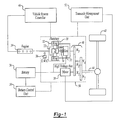
- Figure 1 demonstrates just one possible configuration, specifically a parallel/series hybrid electric vehicle (powersplit) configuration.
- a planetary gear set 20 mechanically couples a carrier gear 22 to an engine 24 with a one-way clutch 26 to prevent the engine from rotating in a counter clock wise (CCW) direction.
- the planetary gear set 20 also mechanically couples a sun gear 28 to a generator motor 30 and a ring (output) gear 32.
- the generator motor 30 also mechanically links to a generator brake 34 and is electrically linked to an electric energy storage device (battery) 36 to receive electric energy converted from mechanical energy by the generator motor 30.
- a traction motor 38 is mechanically coupled to the ring gear 32 of the planetary gear set 20 via a second gear set 40 and is electrically linked to the battery 36.
- the ring gear 32 of the planetary gear set 20 and the traction motor 38 are mechanically coupled to drive wheels 42 via an output shaft 44.
- the mechanical coupling represents collectively a power transmission device, the power transmission devise being connected to the engine 24, the traction motor 38 and the generator motor 30.
- This power transmission device can be configured to have at least one forward drive position to move the HEV in a forward direction and at least one reverse drive position to move the HEV in a reverse direction.
- a driver operated drive position selector (gear selector) (not shown) determines whether the vehicle is to move in the reverse direction.
- the planetary gear set 20 splits the engine 24 output energy into a series path from the engine 24 to the generator motor 30 and a parallel path from the engine 24 to the drive wheels 42.
- Engine 24 speed can be controlled by varying the split to the series path while maintaining the mechanical connection through the parallel path.
- the traction motor 38 augments the engine 24 power to the drive wheels 42 on the parallel path through the second gear set 40.
- the traction motor 38 also provides the opportunity to use energy directly from the series path, essentially running off power created by the generator motor 30. This reduces losses associated with converting energy into and out of chemical energy in the battery 36 and allows all engine 24 energy, minus conversion losses, to reach the drive wheels 42.
- a vehicle system controller (VSC) 46 controls many components in this HEV configuration by connecting to each component's controller.
- An engine control unit (ECU) (not shown)connects to the engine 24 via a hardwire interface.
- the ECU and VSC 46 can be based in the same unit, but are actually separate controllers.
- the VSC 46 communicates with the ECU, as well as a battery control unit (BCU) 50 and a transaxle management unit (TMU) 52 through a communication network such as a controller area network (CAN) 54.
- the BCU 50 connects to the battery 36 via a hardwire interface.
- the TMU 52 controls the generator motor 30 and traction motor 38 via a hardwire interface.
- the power flow illustrated in Figure 2 demonstrates part of the traction motor 38 output ( ⁇ r ⁇ r required to overcome the engine 24 output at the ring gear 32) is also part of the generator motor 30 input, which generates electricity. Clearly, this is a power circulation between the traction motor 38 and the generator motor 30, which results in power circulation loss in the powertrain system.
- ⁇ g ⁇ e ⁇ e is the engine's 24 electrical output power (through the generator motor 30)
- P v / ⁇ m is the traction motor's 38 input power (electrical) required to propel the vehicle
- (1/ ⁇ m - ⁇ g ) ⁇ r ⁇ r is the power circulation loss between the traction motor 38 and generator motor 30. If the power circulation loss is greater than or close to the engine's 24 electrical output power, there is no benefit to operate the engine 24 since the engine 24 output only generates heat in the traction motor 38 and generator motor 30, and does not charge the battery 36.
- VSC 46 To ensure the benefit of operating the engine 24 when the vehicle travels in reverse and the battery 36 SOC is low, it is necessary for the VSC 46 to control the powertrain system properly to avoid the result illustrated above.
- the present invention is a control strategy within the VSC 46 to efficiently control the illustrated powersplit HEV powertrain system when the vehicle travels in reverse and the battery 36 SOC is low.
- the reverse drive mode controller is activated when the drive position selector is in the reverse drive mode.
- the present invention operates the powertrain system efficiently and prevents the battery 36 SOC from continuously falling while meeting the driver's demand.
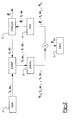
- the strategy is illustrated in Figure 3.
- the reverse drive mode controller strategy first reads the following vehicle inputs 58: PRND position, driver's torque request at the motor ( ⁇ d_req@m ), generator torque ( ⁇ g ) and speed ( ⁇ g ), vehicle speed (to calculate ring gear speed ⁇ r ), engine speed ( ⁇ e ), and engine and generator status.
- PRND position represents a driver operated drive position selector, or gear selector, (not shown) that is manually shifted by the vehicle driver. If the gear selector is in the "R" position, the driver has requested the vehicle to move in reverse.
- Step 62 the strategy next determines if the gear selector is in the "R" position. If no, the strategy ends.
- Step 68 determines at Step 68 whether the W benefit is greater than or equal to a first predetermined value K w . This value indicates it is desirable to run the engine 24 to charge the battery 36.
- the strategy next determines at Step 72 whether the sum of the driver's torque request at motor ( ⁇ d_req@m ) plus the generator motor 30 torque reflected at the motor shaft ( ⁇ g T, where T is the gear ratio from generator to motor and is well known in the prior art) is greater than the predetermined maximum motor torque ( ⁇ m_max ). If the W benefit is less than K w , the strategy executes a stop engine process at Step 70 and ends the strategy.
- the strategy calculates a new generator motor 30 torque request ( ⁇ g_req ) at Step 74 so that the driver's torque request is not compromised and the vehicle reverse acceleration performance meets driver demand.
- the strategy determines at Step 78 whether the new generator motor 30 torque request ( ⁇ g_req ) is greater than or equal to a second predetermined value ( ⁇ g_min ). This implies the generator motor's 30 torque can be accurately controlled. If ( ⁇ g_req ) is greater than or equal to the second predetermined value ( ⁇ g_min ) at Step 78, the strategy proceeds to determine the calculated generator motor 30 speed ( ⁇ g_cal ) for the given new generator motor 30 torque request at Step 80. Otherwise, the strategy proceeds to execute the stop engine process at Step 70 and ends the strategy.
- a new engine 24 speed ( ⁇ e ) can be determined and then the calculated generator motor 30 speed ( ⁇ g_cal ) of Step 80 can be derived based on the new engine 24 speed and ring gear 32 speed (equivalent to present vehicle speed).
- Step 82 the strategy determines whether the calculated generator motor 30 speed ( ⁇ g_cal ) is less than or equal to a predetermined maximum generator motor 30 speed ( ⁇ g_max ). If yes, the strategy proceeds to Step 76 (described above) to determine the new traction motor 38 torque request to meet the driver's demand. This motor torque request compensates the ring gear 32 torque resulted from the engine 24 output to meet the driver's demand. If the calculated generator motor 30 speed ( ⁇ g_cal ) is greater than the maximum generator motor 30 speed ( ⁇ g_max ) at Step 82, the strategy proceeds to execute the stop engine process at Step 70 and the strategy ends.
Abstract
Description
- The present invention relates generally to a hybrid electric vehicle (HEV), and specifically to a strategy to control a split powertrain HEV while the vehicle travels in reverse and vehicle state-of-charge (SOC) is low.
- The need to reduce fossil fuel consumption and emissions in automobiles and other vehicles predominately powered by internal combustion engines (ICES) is well known. Vehicles powered by electric motors attempt to address these needs. Another alternative solution is to combine a smaller ICE with electric motors into one vehicle. Such vehicles combine the advantages of an ICE vehicle and an electric vehicle and are typically called hybrid electric vehicles (HEVs). See generally, U.S. Pat. No. 5,343,970 to Severinsky.
- The HEV is described in a variety of configurations. Many HEV patents disclose systems where an operator is required to select between electric and internal combustion operation. In other configurations, the electric motor drives one set of wheels and the ICE drives a different set.
- Other, more useful, configurations have developed. For example, a series hybrid electric vehicle (SHEV) configuration is a vehicle with an engine (most typically an ICE) connected to an electric motor called a generator. The generator, in turn, provides electricity to a battery and another electric motor, called a traction motor. In the SHEV, the traction motor is the sole source of wheel torque. There is no mechanical connection between the engine and the drive wheels. A parallel hybrid electrical vehicle (PHEV) configuration has an engine (most typically an ICE) and an electric motor that work together in varying degrees to provide the necessary wheel torque to drive the vehicle. Additionally, in the PHEV configuration, the motor can be used as a generator to charge the battery from the power produced by the ICE.
- A parallel/series hybrid electric vehicle (PSHEV) has characteristics of both PHEV and SHEV configurations and is sometimes referred to as a "powersplit" configuration. In one of several types of PSHEV configurations, the ICE is mechanically coupled to two electric motors in a planetary gear-set transaxle. A first electric motor, the generator, is connected to a sun gear. The ICE is connected to a carrier gear. A second electric motor, a traction motor, is connected to a ring (output) gear via additional gearing in a transaxle. Engine torque can power the generator to charge the battery. The generator can also contribute to the necessary wheel (output shaft) torque if the system has a one-way clutch. The traction motor is used to contribute wheel torque and to recover braking energy to charge the battery. In this configuration, the generator can selectively provide a reaction torque that may be used to control engine speed. In fact, the engine, generator motor and traction motor can provide a continuous variable transmission (CVT) effect. Further, the HEV presents an opportunity to better control engine idle speed over conventional vehicles by using the generator to control engine speed.
- The desirability of combining an ICE with electric motors is clear. There is great potential for reducing vehicle fuel consumption and emissions with no appreciable loss of vehicle performance or drive-ability. The HEV allows the use of smaller engines, regenerative braking, electric boost, and even operating the vehicle with the engine shutdown. Nevertheless, new ways must be developed to optimize the HEV's potential benefits.
- One such area of HEV development is controlling a powersplit HEV while traveling in reverse. In the prior art, a reverse gear in a transmission is engaged when the vehicle operator moves a shift lever to the reverse, or "R", position. In an HEV, a variety of powertrain configurations based on vehicle conditions can require new strategies to move the vehicle in reverse.
- A strategy for moving an HEV in reverse is known in the prior art. See U.S. Patent No. 5,847,469 to Tabata et al. Tabata et al. describes an HEV using a conventional transmission to power the vehicle's wheels. The patent describes a system for the electric traction motor alone to reverse the direction of the vehicle without reversing the rotation of the motor so long as there is enough battery charge. Otherwise, the engine is started to assist the motor.
- A conventional transmission with a reverse gear could be considered an inefficient and unnecessary complication and expense in a split powertrain HEV. Alternatively, the electric traction motor alone is used to propel the vehicle in reverse direction. When moving in reverse, the ring gear torque, resulting from engine output, goes against the vehicle moving in reverse. Thus, using the engine while the vehicle is in reverse is undesirable. Nevertheless, if battery state-of-charge (SOC) is low, the engine may need to run to power a generator to charge the battery and allow the motor to operate.
- Unfortunately, no strategy is known to control a split powertrain HEV while the vehicle travels in reverse with the engine running because the battery state-of-charge (SOC) is low and the electric traction motor requires electricity produced by the generator for reverse motive power.
- According to a first aspect of the invention there is provided a powersplit hybrid electric vehicle powertrain comprising an engine, a traction motor, a generator motor, an electric energy storage device for storing electric energy, the electric energy storage device being connected to the traction motor to power the traction motor and to the generator motor to receive energy generated by the generator motor characterised in that the powertrain further comprises of a power transmission device including at least one forward drive position to move the vehicle in a forward direction and at least one reverse drive position to move the vehicle in a reverse direction, the power transmission device being connected to the engine, the traction motor, and the generator motor, a driver operable drive position selector comprising a reverse drive mode and a vehicle system controller comprising a reverse drive mode controller activated when the drive position selector is in the reverse drive mode, wherein the reverse drive mode controller is operable to prevent the electric energy storage device state-of-charge from continuously falling while meeting driver demand.
- Preferably, the reverse drive mode controller may be operable to determine whether the engine and generator motor are running; to calculate a benefit power from the engine if the engine and the generator motor are running; to compare the benefit power with a first predetermined value; to determine whether a driver torque request plus the traction motor torque is greater than a predetermined maximum traction motor torque if the benefit power is greater than or equal to the first predetermined value; to calculate a new generator motor torque request if the determination of whether the driver torque request plus the generator motor torque is greater than the predetermined maximum torque; to determine whether the new generator motor torque request is greater than or equal to a second predetermined value; to calculate a new generator motor speed for the new generator motor torque request if the new generator motor torque request is greater than or equal to the second predetermined value; to determine whether the new generator motor speed is less than or equal to a maximum generator motor speed and to determine a new generator motor torque request if the new generator motor speed is less than or equal to the maximum generator motor speed.
- The benefit power from the engine may be determined by the equation:
- The calculation of the new generator motor torque request may be determined by the equation:
- The new traction motor torque request may be determined by adding the driver torque request to the new generator motor torque request.
- The reverse drive mode controller may further comprise of a stop engine command if the benefit power is less than the first predetermined value.
- The reverse drive mode controller may further comprise of a stop engine command if the new generator motor torque request is less than the second predetermined value.
- The reverse drive mode controller may further comprise of a stop engine command if the new generator motor speed is greater than a maximum generator motor speed.
- According to a second aspect of the invention there is provided a method to control reverse drive mode in a hybrid electric vehicle when a drive position selector is in a reverse drive mode to prevent an electric energy storage device state-of-charge from continuously falling while meeting driver demand, characterised in that the method comprises of the steps of determining whether an engine and generator motor are running; calculating a benefit power from the engine if the engine and the generator motor are running; comparing the benefit power with a first predetermined value; determining whether a driver torque request plus generator motor torque is greater than a predetermined maximum traction motor torque if the benefit power is greater than or equal to the first predetermined value; calculating a new generator motor torque request if the step of determining whether the driver torque request plus the generator motor torque is greater than the predetermined maximum traction motor torque; determining whether the new generator motor torque request is greater than or equal to a second predetermined value; calculating a new generator motor speed for the new generator motor torque request if the new generator motor torque request is greater than or equal to the second predetermined value; determining whether the new generator motor speed is less than or equal to a maximum generator motor speed and determining a new traction motor torque request if the new generator motor speed is less than or equal to the maximum generator motor speed.
- The step of determining the benefit power from the engine may use the equation:
- The calculation of the new generator motor torque request may be determined by the equation:
- The step of determining the new traction motor torque request may be achieved by adding the driver torque request to the new generator motor torque request.
- The method may further comprise the step of stopping the engine if the benefit power is less than the first predetermined value.
- The method may further comprise the step of stopping the engine if the new generator motor torque request is less than the second predetermined value.
- The method may further comprise the step of stopping the engine if the new generator motor speed is greater than the maximum generator motor speed.
- The invention will now be described by way of example with reference to the accompanying drawing of which:-
- Figure 1 illustrates a general hybrid electric vehicle (HEV) configuration;
- Figure 2 illustrates the power flow within the powertrain; and
- Figure 3 illustrates the strategy of the present invention for an HEV while travelling in reverse.
-
- The present invention relates to electric vehicles and, more particularly, to hybrid electric vehicles (HEVs). Figure 1 demonstrates just one possible configuration, specifically a parallel/series hybrid electric vehicle (powersplit) configuration.
- In a basic HEV, a planetary gear set 20 mechanically couples a
carrier gear 22 to anengine 24 with a one-way clutch 26 to prevent the engine from rotating in a counter clock wise (CCW) direction. The planetary gear set 20 also mechanically couples asun gear 28 to agenerator motor 30 and a ring (output)gear 32. Thegenerator motor 30 also mechanically links to agenerator brake 34 and is electrically linked to an electric energy storage device (battery) 36 to receive electric energy converted from mechanical energy by thegenerator motor 30. Atraction motor 38 is mechanically coupled to thering gear 32 of the planetary gear set 20 via a second gear set 40 and is electrically linked to thebattery 36. Thering gear 32 of the planetary gear set 20 and thetraction motor 38 are mechanically coupled to drivewheels 42 via anoutput shaft 44. The mechanical coupling represents collectively a power transmission device, the power transmission devise being connected to theengine 24, thetraction motor 38 and thegenerator motor 30. This power transmission device can be configured to have at least one forward drive position to move the HEV in a forward direction and at least one reverse drive position to move the HEV in a reverse direction. A driver operated drive position selector (gear selector) (not shown) determines whether the vehicle is to move in the reverse direction. - The planetary gear set 20, splits the
engine 24 output energy into a series path from theengine 24 to thegenerator motor 30 and a parallel path from theengine 24 to thedrive wheels 42.Engine 24 speed can be controlled by varying the split to the series path while maintaining the mechanical connection through the parallel path. Thetraction motor 38 augments theengine 24 power to thedrive wheels 42 on the parallel path through the second gear set 40. Thetraction motor 38 also provides the opportunity to use energy directly from the series path, essentially running off power created by thegenerator motor 30. This reduces losses associated with converting energy into and out of chemical energy in thebattery 36 and allows allengine 24 energy, minus conversion losses, to reach thedrive wheels 42. - A vehicle system controller (VSC) 46 controls many components in this HEV configuration by connecting to each component's controller. An engine control unit (ECU) (not shown)connects to the
engine 24 via a hardwire interface. The ECU and VSC 46 can be based in the same unit, but are actually separate controllers. The VSC 46 communicates with the ECU, as well as a battery control unit (BCU) 50 and a transaxle management unit (TMU) 52 through a communication network such as a controller area network (CAN) 54. The BCU 50 connects to thebattery 36 via a hardwire interface. TheTMU 52 controls thegenerator motor 30 andtraction motor 38 via a hardwire interface. - All vehicles require movement in a reverse direction from time to time. Such movement usually begins with a driver manually shifting a gear selector to a reverse (or "R") position. In the powertrain configuration of the present invention, the
engine 24 does not provide primary drive to the vehicle while traveling in reverse. There is no true rear drive shifting means in that there is no discrete exchange of power flow elements that produces a reverse range as opposed to a forward range. In fact, torque from theengine 24 while in reverse would work against thetraction motor 38 traveling in reverse. Nevertheless, to operate thetraction motor 38 in a reverse rotation, theengine 24 may be needed to charge thebattery 36 if a low state-of-charge (SOC) exists. Duringengine 24 operation to generate the electricity, theengine 24 would produce torque through the second gear set 40 that would attempt to drive the vehicle in a forward direction. It is only by the balance of the relative forward and reverse torques that the net vehicle rearward torque is augmented. - For example, if the vehicle is moving in reverse at a certain vehicle speed (equivalent to ωr), the traction motor's 38 output power required for the vehicle speed is Pv. Also assume the
engine 24 is running at a constant power output (τe ωe), and both efficiencies of the planetary gear set 20 and the second gear set 40 are one. The resultedring output gear 32 torque from theengine 24 torque (τe) is τr = τe/(1+ρ). ρ is the gear ratio between thesun gear 28 and the ring gear 32 (Ns/Nr). ηg and ηm are the efficiencies for the generator motor and the traction motor respectively. The power flow within the powertrain under these assumptions is illustrated in Figure 2. The following symbols listed below will assist in understanding the present invention: - ωr =
- ring gear speed
- ωe =
- engine speed
- Pv =
- output power
- τeωe =
- engine power output
- τe =
- engine torque
- τr =
- ring gear torque
- ρ =
- gear ratio between sun gear and ring gear
- Ns =
- number of teeth in sun gear
- Nr =
- number of teeth in ring gear
- ηg =
- overall efficiency for generator
- ηm =
- overall efficiency for motor
- Pbatt =
- power charging the battery
- ηgτeωe =
- engine's electrical output power (through generator)
- Pv/ηm =
- motor's input power (electrical)
- (1/ηm - ηg)τrωr =
- power circulation loss between motor and generator
- τd_req@m =
- driver's torque request at the motor
- τg =
- generator torque
- ωg =
- generator speed
- Wbenefit =
- benefit power from the engine
- Kw =
- a predetermined Wbenefit value
- τm_max =
- maximum motor torque
- τg_req =
- generator torque request
- τg_min =
- generator torque request minimum
- ωg_cal =
- calculated generator speed
- ωg_max =
- maximum generator speed.
- T =
- gear ratio from generator to motor
- The power flow illustrated in Figure 2 demonstrates part of the
traction motor 38 output (τrωr required to overcome theengine 24 output at the ring gear 32) is also part of thegenerator motor 30 input, which generates electricity. Clearly, this is a power circulation between thetraction motor 38 and thegenerator motor 30, which results in power circulation loss in the powertrain system. - The power charging the
battery 36 is Pbatt and is shown by: - In this example, ηgτeωe is the engine's 24 electrical output power (through the generator motor 30), Pv/ηm is the traction motor's 38 input power (electrical) required to propel the vehicle, and (1/ηm - ηg)τrωr is the power circulation loss between the
traction motor 38 andgenerator motor 30. If the power circulation loss is greater than or close to the engine's 24 electrical output power, there is no benefit to operate theengine 24 since theengine 24 output only generates heat in thetraction motor 38 andgenerator motor 30, and does not charge thebattery 36. - To ensure the benefit of operating the
engine 24 when the vehicle travels in reverse and thebattery 36 SOC is low, it is necessary for the VSC 46 to control the powertrain system properly to avoid the result illustrated above. - The present invention is a control strategy within the VSC 46 to efficiently control the illustrated powersplit HEV powertrain system when the vehicle travels in reverse and the
battery 36 SOC is low. The reverse drive mode controller is activated when the drive position selector is in the reverse drive mode. The present invention operates the powertrain system efficiently and prevents thebattery 36 SOC from continuously falling while meeting the driver's demand. The strategy is illustrated in Figure 3. - At
Step 60, the reverse drive mode controller strategy first reads the following vehicle inputs 58: PRND position, driver's torque request at the motor (τd_req@m), generator torque (τg) and speed (ωg), vehicle speed (to calculate ring gear speed ωr), engine speed (ωe), and engine and generator status. PRND position represents a driver operated drive position selector, or gear selector, (not shown) that is manually shifted by the vehicle driver. If the gear selector is in the "R" position, the driver has requested the vehicle to move in reverse. - At
Step 62, the strategy next determines if the gear selector is in the "R" position. If no, the strategy ends. - If "R" is selected at
Step 62, the strategy next determines if both theengine 24 andgenerator motor 30 are running atStep 64. If no, the strategy ends. If both theengine 24 andgenerator motor 30 are running atStep 64, the strategy calculates the benefit power from the engine 24 Wbenefit atStep 66 using the equation Wbenefit = ηgτeωe - (1/ηm-ηg )τrωr. - Next the strategy determines at
Step 68 whether the Wbenefit is greater than or equal to a first predetermined value Kw. This value indicates it is desirable to run theengine 24 to charge thebattery 36. - If Wbenefit is greater than or equal to Kw at
Step 68, the strategy next determines atStep 72 whether the sum of the driver's torque request at motor (τd_req@m) plus thegenerator motor 30 torque reflected at the motor shaft (τgT, where T is the gear ratio from generator to motor and is well known in the prior art) is greater than the predetermined maximum motor torque (τm_max). If the Wbenefit is less than Kw, the strategy executes a stop engine process atStep 70 and ends the strategy. - If the sum is greater than the predetermined maximum motor torque at
Step 72, the strategy calculates anew generator motor 30 torque request (τg_req) atStep 74 so that the driver's torque request is not compromised and the vehicle reverse acceleration performance meets driver demand. The calculation is as follows: τg_req = (τm_max-τd_req@m)/T. Otherwise, the strategy proceeds to calculate anew traction motor 38 torque request (τm_req) atStep 76 using: τm_req = τd_req@m + τg_req T and the strategy ends. - Next, the strategy determines at
Step 78 whether thenew generator motor 30 torque request (τg_req) is greater than or equal to a second predetermined value (τg_min). This implies the generator motor's 30 torque can be accurately controlled. If (τg_req) is greater than or equal to the second predetermined value (τg_min) atStep 78, the strategy proceeds to determine thecalculated generator motor 30 speed (ωg_cal) for the givennew generator motor 30 torque request atStep 80. Otherwise, the strategy proceeds to execute the stop engine process atStep 70 and ends the strategy. With thenew generator motor 30 torque request (τg_req), anew engine 24 speed (ωe) can be determined and then thecalculated generator motor 30 speed (ωg_cal) ofStep 80 can be derived based on thenew engine 24 speed andring gear 32 speed (equivalent to present vehicle speed). - Next, at
Step 82, the strategy determines whether thecalculated generator motor 30 speed (ωg_cal) is less than or equal to a predeterminedmaximum generator motor 30 speed (ωg_max). If yes, the strategy proceeds to Step 76 (described above) to determine thenew traction motor 38 torque request to meet the driver's demand. This motor torque request compensates thering gear 32 torque resulted from theengine 24 output to meet the driver's demand. If thecalculated generator motor 30 speed (ωg_cal) is greater than themaximum generator motor 30 speed (ωg_max) atStep 82, the strategy proceeds to execute the stop engine process atStep 70 and the strategy ends. - The above-described embodiment of the invention is provided purely for purposes of example. Many other variations, modifications, and applications of the invention may be made.
Claims (10)
- A powersplit hybrid electric vehicle powertrain comprising an engine (24), a traction motor (38), a generator motor (30), an electric energy storage device (36) for storing electric energy, the electric energy storage device (36) being connected to the traction motor (38) to power the traction motor (38) and to the generator motor (30) to receive energy generated by the generator motor (30) characterised in that the powertrain further comprises of a power transmission device (20) including at least one forward drive position to move the vehicle in a forward direction and at least one reverse drive position to move the vehicle in a reverse direction, the power transmission device being connected to the engine (24), the traction motor (38), and the generator motor (30), a driver operable drive position selector comprising a reverse drive mode and a vehicle system controller (46) comprising a reverse drive mode controller activated when the drive position selector is in the reverse drive mode, wherein the reverse drive mode controller is operable to prevent the electric energy storage device state-of-charge from continuously falling while meeting driver demand.
- A powertrain as claimed in claim 1 wherein the reverse drive mode controller is operable to determine whether the engine and generator motor are running; to calculate a benefit power from the engine if the engine and the generator motor are running; to compare the benefit power with a first predetermined value; to determine whether a driver torque request plus the traction motor torque is greater than a predetermined maximum traction motor torque if the benefit power is greater than or equal to the first predetermined value; to calculate a new generator motor torque request if the determination of whether the driver torque request plus the generator motor torque is greater than the predetermined maximum torque; to determine whether the new generator motor torque request is greater than or equal to a second predetermined value; to calculate a new generator motor speed for the new generator motor torque request if the new generator motor torque request is greater than or equal to the second predetermined value; to determine whether the new generator motor speed is less than or equal to a maximum generator motor speed and to determine a new generator motor torque request if the new generator motor speed is less than or equal to the maximum generator motor speed.
- A powertrain as claimed in claim 2 wherein the new traction motor torque request is determined by adding the driver torque request to the new generator motor torque request.
- A method to control reverse drive mode in a hybrid electric vehicle when a drive position selector is in a reverse drive mode to prevent an electric energy storage device state-of-charge from continuously falling while meeting driver demand, characterised in that the method comprises of the steps of determining whether an engine and generator motor are running; calculating a benefit power from the engine if the engine and the generator motor are running; comparing the benefit power with a first predetermined value; determining whether a driver torque request plus generator motor torque is greater than a predetermined maximum traction motor torque if the benefit power is greater than or equal to the first predetermined value; calculating a new generator motor torque request if the step of determining whether the driver torque request plus the generator motor torque is greater than the predetermined maximum traction motor torque; determining whether the new generator motor torque request is greater than or equal to a second predetermined value; calculating a new generator motor speed for the new generator motor torque request if the new generator motor torque request is greater than or equal to the second predetermined value; determining whether the new generator motor speed is less than or equal to a maximum generator motor speed and determining a new traction motor torque request if the new generator motor speed is less than or equal to the maximum generator motor speed.
- A method as claimed in claim 4 wherein the step of determining the benefit power from the engine uses the equation:
- A method as claimed in claim 4 or in claim 5 wherein the calculation of the new generator motor torque request is determined by the equation:
- A method as claimed in any of claims 4 to 6 wherein the step of determining the new traction motor torque request is achieved by adding the driver torque request to the new generator motor torque request.
- A method as claimed in any of claims 4 to 7 further comprising the step of stopping the engine if the benefit power is less than the first predetermined value.
- A method as claimed in any of claims 4 to 8 further comprising the step of stopping the engine if the new generator motor torque request is less than the second predetermined value.
- A method as claimed in any of claims 4 to 9 further comprising the step of stopping the engine if the new generator motor speed is greater than the maximum generator motor speed.
Applications Claiming Priority (2)
| Application Number | Priority Date | Filing Date | Title |
|---|---|---|---|
| US865100 | 2001-05-24 | ||
| US09/865,100 US6603215B2 (en) | 2001-05-24 | 2001-05-24 | Hybrid electric vehicle control strategy while traveling in reverse |
Publications (3)
| Publication Number | Publication Date |
|---|---|
| EP1260397A2 true EP1260397A2 (en) | 2002-11-27 |
| EP1260397A3 EP1260397A3 (en) | 2006-08-16 |
| EP1260397B1 EP1260397B1 (en) | 2008-03-26 |
Family
ID=25344717
Family Applications (1)
| Application Number | Title | Priority Date | Filing Date |
|---|---|---|---|
| EP02253322A Expired - Lifetime EP1260397B1 (en) | 2001-05-24 | 2002-05-13 | A control strategy for a hybrid vehicle while traveling in reverse |
Country Status (5)
| Country | Link |
|---|---|
| US (1) | US6603215B2 (en) |
| EP (1) | EP1260397B1 (en) |
| JP (1) | JP3795833B2 (en) |
| CA (1) | CA2387317A1 (en) |
| DE (1) | DE60225753T2 (en) |
Cited By (8)
| Publication number | Priority date | Publication date | Assignee | Title |
|---|---|---|---|---|
| GB2406318A (en) * | 2003-09-22 | 2005-03-30 | Ford Global Tech Llc | A hybrid vehicle powertrain with improved reverse drive performance |
| GB2416746A (en) * | 2004-07-28 | 2006-02-08 | Ford Global Tech Llc | Hybrid electric vehicle powertrain |
| US7576501B2 (en) | 2006-10-11 | 2009-08-18 | Ford Global Technologies, Llc | Method for controlling a hybrid electric vehicle powertrain with divided power flow paths |
| CN102079306A (en) * | 2009-11-30 | 2011-06-01 | 通用汽车环球科技运作公司 | Method of determining output torque constraints for a powertrain |
| EP2065274A3 (en) * | 2007-11-04 | 2012-04-11 | GM Global Technology Operations LLC | Method to manage a high voltage system in a hybrid powertrain system |
| WO2015110896A1 (en) * | 2014-01-24 | 2015-07-30 | Toyota Jidosha Kabushiki Kaisha | Control device for hybrid vehicle and hybrid vehicle |
| US9545839B2 (en) | 2008-09-05 | 2017-01-17 | Ford Global Technologies, Llc | Hybrid electric vehicle powertrain with enhanced reverse drive performance |
| CN107521488A (en) * | 2016-06-22 | 2017-12-29 | 福特全球技术公司 | Improve the system and method for electric vehicle counter steer ability |
Families Citing this family (59)
| Publication number | Priority date | Publication date | Assignee | Title |
|---|---|---|---|---|
| US7086977B2 (en) | 2001-05-03 | 2006-08-08 | Ford Global Technologies, Llc | Transmission arrangements for hybrid electric vehicles |
| KR100590862B1 (en) * | 2003-04-29 | 2006-06-19 | 삼성전자주식회사 | Apparatus and method for processing a data call in a private wireless high-speed data system |
| JP3807386B2 (en) * | 2003-06-05 | 2006-08-09 | トヨタ自動車株式会社 | Control device for hybrid vehicle |
| US7061131B2 (en) * | 2003-06-13 | 2006-06-13 | General Electric Company | Method and system for optimizing energy storage in hybrid off-highway vehicle systems and trolley connected OHV systems |
| US7216729B2 (en) * | 2003-09-19 | 2007-05-15 | Ford Global Technologies, Llc | Method and system of requesting engine on/off state in a hybrid electric vehicle |
| CN1298572C (en) * | 2003-09-26 | 2007-02-07 | 清华大学 | MPC500 process type electric car multi-energy power assembly control device |
| US7090613B2 (en) * | 2004-05-15 | 2006-08-15 | General Motors Corporation | Method of providing electric motor torque reserve in a hybrid electric vehicle |
| US7107956B2 (en) * | 2004-07-30 | 2006-09-19 | Ford Global Technologies, Llc | Vehicle and method for controlling engine start in a vehicle |
| US7404784B2 (en) | 2005-11-17 | 2008-07-29 | Autoliv Asp, Inc. | Fuel saving sensor system |
| DE102005062869A1 (en) * | 2005-12-29 | 2007-07-05 | Robert Bosch Gmbh | Motor vehicle`s hybrid drive controlling method, involves carrying out torque comparison between allowable torque and additional torque, and comparing allowable torque with reference torques for two individual drives of hybrid drive |
| US7489048B2 (en) * | 2006-01-09 | 2009-02-10 | General Electric Company | Energy storage system for electric or hybrid vehicle |
| US7568537B2 (en) * | 2006-01-09 | 2009-08-04 | General Electric Company | Vehicle propulsion system |
| US7780562B2 (en) * | 2006-01-09 | 2010-08-24 | General Electric Company | Hybrid vehicle and method of assembling same |
| US7595597B2 (en) * | 2006-01-18 | 2009-09-29 | General Electric Comapany | Vehicle propulsion system |
| JP4502136B2 (en) * | 2006-04-13 | 2010-07-14 | スズキ株式会社 | Drive control apparatus for hybrid vehicle |
| JP4217258B2 (en) * | 2006-09-21 | 2009-01-28 | 本田技研工業株式会社 | Hybrid vehicle |
| JP5245560B2 (en) * | 2008-06-18 | 2013-07-24 | マツダ株式会社 | Vehicle drive control device and control method |
| US8013548B2 (en) * | 2008-10-14 | 2011-09-06 | General Electric Company | System, vehicle and related method |
| US20120112710A1 (en) * | 2010-11-05 | 2012-05-10 | Ross George Haldeman | Electric machine to regulate work output rotational speed from infinitely variable transmissions by the creation of electrical energy |
| DE112011104861B4 (en) | 2011-02-09 | 2021-12-09 | Suzuki Motor Corporation | Power source control device for hybrid automobile and power source control method for hybrid automobile and hybrid automobile |
| US9108501B2 (en) * | 2011-07-05 | 2015-08-18 | Ford Global Technologies, Llc | Multi-mode powersplit powertrain for electric vehicle |
| CA2810945C (en) | 2012-03-26 | 2018-08-14 | Mcmaster University | Powertrain system for hybrid vehicles having multiple modes of operation |
| US9145136B2 (en) | 2012-03-26 | 2015-09-29 | Mcmaster University | Powertrain system for hybrid vehicles having compound and split modes of operation |
| DE102012213278A1 (en) * | 2012-07-27 | 2014-01-30 | Zf Friedrichshafen Ag | Method for controlling working machine e.g. construction machine, involves operating energy storage when reversal of direction of travel is carried out for hybrid system |
| US8894526B2 (en) | 2012-12-03 | 2014-11-25 | Ford Global Technologies, Llc | Powertrain for a hybrid electric vehicle |
| JP6324157B2 (en) * | 2014-03-27 | 2018-05-16 | インターナショナル・ビジネス・マシーンズ・コーポレーションInternational Business Machines Corporation | Information processing apparatus, information processing method, and program |
| JP6090273B2 (en) * | 2014-09-17 | 2017-03-08 | トヨタ自動車株式会社 | Hybrid car |
| US9783183B2 (en) | 2015-02-23 | 2017-10-10 | Ford Global Technologies, Llc | Battery charging strategy in a hybrid vehicle |
| US9771066B2 (en) | 2015-09-25 | 2017-09-26 | Hyundai Motor Company | Backward driving control method of hybrid vehicle |
| US10487918B2 (en) * | 2016-02-29 | 2019-11-26 | Deere & Company | Integrated starter-generator device with power transmission |
| US10591025B2 (en) * | 2016-02-29 | 2020-03-17 | Deere & Company | Integrated starter-generator device with power transmission |
| US10632996B2 (en) | 2017-05-09 | 2020-04-28 | Ford Global Technologies, Llc | Systems and methods for controlling a hybrid electric powertrain |
| US10479187B2 (en) | 2017-11-29 | 2019-11-19 | Deere & Company | Integrated hybrid power system for work vehicle |
| BR102018071693A2 (en) * | 2017-12-07 | 2019-06-25 | Deere & Company | DEVICE COMBINED PROPELLER STARTER AND POWER GENERATOR, AND, DRIVE TRAIN ASSEMBLY |
| US10519920B2 (en) | 2018-01-17 | 2019-12-31 | Deere & Company | Automatic two-mode high reduction power transmission system |
| CN110816306A (en) * | 2018-07-23 | 2020-02-21 | 中车株洲电力机车研究所有限公司 | Diesel power generation electric drive whole vehicle system and vehicle |
| US11413972B2 (en) * | 2019-01-17 | 2022-08-16 | Atieva, Inc. | Control system to eliminate power train backlash |
| US10920730B2 (en) | 2019-04-16 | 2021-02-16 | Deere & Company | Multi-mode integrated starter-generator device with dog clutch arrangement |
| US10920733B2 (en) | 2019-04-16 | 2021-02-16 | Deere & Company | Multi-mode integrated starter-generator device with preloaded clutch |
| US10975937B2 (en) | 2019-04-16 | 2021-04-13 | Deere & Company | Multi-mode integrated starter-generator device with cam arrangement |
| US11156270B2 (en) | 2019-04-16 | 2021-10-26 | Deere & Company | Multi-mode integrated starter-generator device with transmission assembly mounting arrangement |
| US10968985B2 (en) | 2019-04-16 | 2021-04-06 | Deere & Company | Bi-directional integrated starter-generator device |
| US10933731B2 (en) | 2019-04-16 | 2021-03-02 | Deere & Company | Multi-mode integrated starter-generator device with magnetic cam assembly |
| US10975938B2 (en) | 2019-04-16 | 2021-04-13 | Deere & Company | Multi-mode integrated starter-generator device with electromagnetic actuation assembly |
| US10821820B1 (en) | 2019-04-16 | 2020-11-03 | Deere & Company | Multi-mode starter-generator device transmission with single valve control |
| US11060496B2 (en) | 2019-04-16 | 2021-07-13 | Deere & Company | Multi-mode integrated starter-generator device |
| US10948054B2 (en) | 2019-04-16 | 2021-03-16 | Deere & Company | Multi-mode integrated starter-generator device with solenoid cam actuation apparatus |
| US10900454B1 (en) | 2020-04-03 | 2021-01-26 | Deere & Company | Integrated starter-generator device with unidirectional clutch actuation utilizing a biased lever assembly |
| US11193560B1 (en) | 2020-05-29 | 2021-12-07 | Deere & Company | Work vehicle multi-speed drive assembly with bifurcated clutches |
| US11415199B2 (en) | 2020-05-29 | 2022-08-16 | Deere & Company | Bi-directional multi-speed drive |
| US11326570B1 (en) | 2020-10-26 | 2022-05-10 | Deere & Company | Multi-mode integrated starter-generator device with unidirectional input |
| US11624170B2 (en) | 2021-02-25 | 2023-04-11 | Deere & Company | Work vehicle multi-speed drive assembly with clutch retention mechanism |
| US11866910B2 (en) | 2021-02-25 | 2024-01-09 | Deere & Company | Work vehicle multi-speed drive assembly with output control clutch |
| US11719209B2 (en) | 2021-03-29 | 2023-08-08 | Deere & Company | Integrated starter-generator device with unidirectional clutch actuation utilizing biased lever assembly |
| US11761515B2 (en) | 2021-05-20 | 2023-09-19 | Deere & Company | Work vehicle multi-speed drive assembly with guided dog clutch |
| CN113442724B (en) * | 2021-06-24 | 2022-03-29 | 岚图汽车科技有限公司 | Electric automobile and energy distribution method, system and controller during torque reversing of electric automobile |
| US11686374B2 (en) | 2021-07-23 | 2023-06-27 | Deere & Company | Work vehicle multi-speed drive assembly providing multiple gear ratios at same step ratio |
| US11745720B2 (en) * | 2021-09-28 | 2023-09-05 | Ford Global Technologies, Llc | Methods and system for controlling an engine |
| CN114762851A (en) * | 2022-03-09 | 2022-07-19 | 广汽埃安新能源汽车有限公司 | Spraying method for improving painting rate of outer plate of automobile body |
Citations (1)
| Publication number | Priority date | Publication date | Assignee | Title |
|---|---|---|---|---|
| US5343970A (en) | 1992-09-21 | 1994-09-06 | Severinsky Alex J | Hybrid electric vehicle |
Family Cites Families (20)
| Publication number | Priority date | Publication date | Assignee | Title |
|---|---|---|---|---|
| DE4342735A1 (en) * | 1993-12-15 | 1995-06-22 | Hoehn Bernd Robert Prof Dr | Hybrid drive arrangement for vehicle |
| JP2973920B2 (en) * | 1995-05-24 | 1999-11-08 | トヨタ自動車株式会社 | Hybrid electric vehicle |
| US6054844A (en) * | 1998-04-21 | 2000-04-25 | The Regents Of The University Of California | Control method and apparatus for internal combustion engine electric hybrid vehicles |
| JP3129204B2 (en) * | 1995-10-18 | 2001-01-29 | トヨタ自動車株式会社 | Hybrid drive |
| JP3531332B2 (en) | 1996-02-29 | 2004-05-31 | トヨタ自動車株式会社 | Hybrid drive |
| US5923093A (en) * | 1996-07-02 | 1999-07-13 | Toyota Jidosha Kabushiki Kaisha | Hybrid vehicle drive system adapted to assure smooth brake application by motor/generator or engine |
| US6018694A (en) * | 1996-07-30 | 2000-01-25 | Denso Corporation | Controller for hybrid vehicle |
| WO1998004431A1 (en) * | 1996-07-30 | 1998-02-05 | Denso Corporation | Hybrid car controller |
| JP3097572B2 (en) * | 1996-09-13 | 2000-10-10 | トヨタ自動車株式会社 | Power output device and control method thereof |
| US5730676A (en) * | 1996-10-22 | 1998-03-24 | General Motors Corporation | Three-mode, input-split hybrid transmission |
| JP3767103B2 (en) * | 1997-07-16 | 2006-04-19 | 日産自動車株式会社 | Electric vehicle control device |
| DE19747265B4 (en) * | 1997-10-25 | 2010-11-04 | Zf Friedrichshafen Ag | Hybrid drive for a vehicle |
| CA2312752C (en) * | 1997-12-05 | 2003-07-08 | Toyota Jidosha Kabushiki Kaisha | Hybrid drive system |
| JPH11280512A (en) * | 1998-03-30 | 1999-10-12 | Nissan Motor Co Ltd | Hybrid vehicle |
| US6269290B1 (en) * | 1998-07-01 | 2001-07-31 | Denso Corporation | Engine-motor hybrid vehicle control apparatus and method having engine performance Lessening compensation |
| JP3508559B2 (en) * | 1998-07-24 | 2004-03-22 | 日産自動車株式会社 | Control device for parallel hybrid vehicle |
| JP2000207816A (en) * | 1999-01-13 | 2000-07-28 | Toyota Motor Corp | Information processor for vehicle |
| JP4069556B2 (en) * | 1999-10-07 | 2008-04-02 | トヨタ自動車株式会社 | Control method for power output device |
| JP3327262B2 (en) * | 1999-10-08 | 2002-09-24 | トヨタ自動車株式会社 | Reverse travel device for vehicles |
| US6378638B1 (en) * | 2001-03-14 | 2002-04-30 | New Venture Gear, Inc. | Drive axle for hybrid vehicle |
-
2001
- 2001-05-24 US US09/865,100 patent/US6603215B2/en not_active Expired - Lifetime
-
2002
- 2002-05-13 DE DE60225753T patent/DE60225753T2/en not_active Expired - Lifetime
- 2002-05-13 EP EP02253322A patent/EP1260397B1/en not_active Expired - Lifetime
- 2002-05-23 CA CA002387317A patent/CA2387317A1/en not_active Abandoned
- 2002-05-24 JP JP2002149918A patent/JP3795833B2/en not_active Expired - Lifetime
Patent Citations (1)
| Publication number | Priority date | Publication date | Assignee | Title |
|---|---|---|---|---|
| US5343970A (en) | 1992-09-21 | 1994-09-06 | Severinsky Alex J | Hybrid electric vehicle |
Cited By (14)
| Publication number | Priority date | Publication date | Assignee | Title |
|---|---|---|---|---|
| GB2406318B (en) * | 2003-09-22 | 2007-01-17 | Ford Global Tech Llc | A hybrid vehicle powertrain with improved reverse drive performance |
| US7694762B2 (en) | 2003-09-22 | 2010-04-13 | Ford Global Technologies, Llc | Hybrid vehicle powertrain with improved reverse drive performance |
| GB2406318A (en) * | 2003-09-22 | 2005-03-30 | Ford Global Tech Llc | A hybrid vehicle powertrain with improved reverse drive performance |
| GB2416746A (en) * | 2004-07-28 | 2006-02-08 | Ford Global Tech Llc | Hybrid electric vehicle powertrain |
| GB2416746B (en) * | 2004-07-28 | 2007-09-12 | Ford Global Tech Llc | A hybrid electric powertrain |
| US7576501B2 (en) | 2006-10-11 | 2009-08-18 | Ford Global Technologies, Llc | Method for controlling a hybrid electric vehicle powertrain with divided power flow paths |
| EP2065274A3 (en) * | 2007-11-04 | 2012-04-11 | GM Global Technology Operations LLC | Method to manage a high voltage system in a hybrid powertrain system |
| US8214120B2 (en) | 2007-11-04 | 2012-07-03 | GM Global Technology Operations LLC | Method to manage a high voltage system in a hybrid powertrain system |
| US9545839B2 (en) | 2008-09-05 | 2017-01-17 | Ford Global Technologies, Llc | Hybrid electric vehicle powertrain with enhanced reverse drive performance |
| CN102079306A (en) * | 2009-11-30 | 2011-06-01 | 通用汽车环球科技运作公司 | Method of determining output torque constraints for a powertrain |
| CN102079306B (en) * | 2009-11-30 | 2014-04-02 | 通用汽车环球科技运作公司 | Method of determining output torque constraints for a powertrain |
| WO2015110896A1 (en) * | 2014-01-24 | 2015-07-30 | Toyota Jidosha Kabushiki Kaisha | Control device for hybrid vehicle and hybrid vehicle |
| CN107521488A (en) * | 2016-06-22 | 2017-12-29 | 福特全球技术公司 | Improve the system and method for electric vehicle counter steer ability |
| CN107521488B (en) * | 2016-06-22 | 2022-07-26 | 福特全球技术公司 | System and method for improving reverse driving capability of electric vehicle |
Also Published As
| Publication number | Publication date |
|---|---|
| DE60225753D1 (en) | 2008-05-08 |
| US20030001391A1 (en) | 2003-01-02 |
| CA2387317A1 (en) | 2002-11-24 |
| EP1260397B1 (en) | 2008-03-26 |
| US6603215B2 (en) | 2003-08-05 |
| JP2003083111A (en) | 2003-03-19 |
| JP3795833B2 (en) | 2006-07-12 |
| DE60225753T2 (en) | 2009-05-07 |
| EP1260397A3 (en) | 2006-08-16 |
Similar Documents
| Publication | Publication Date | Title |
|---|---|---|
| EP1260397B1 (en) | A control strategy for a hybrid vehicle while traveling in reverse | |
| US6590299B2 (en) | Hybrid electric vehicle control strategy to provide vehicle creep and hill holding | |
| JP3947082B2 (en) | Control method of hybrid electric vehicle to obtain maximum fully open acceleration performance | |
| KR101725270B1 (en) | Control apparatus for dynamic power transmission apparatus | |
| EP1731346B1 (en) | Power output device and automobile mounted with the same | |
| US7216729B2 (en) | Method and system of requesting engine on/off state in a hybrid electric vehicle | |
| EP1524145A2 (en) | Drive train for hybrid vehicle | |
| EP3501869B1 (en) | Drive force control system for hybrid vehicles | |
| US20030100395A1 (en) | Powertrain for hybrid electric vehicles | |
| CN109720333B (en) | Control device for hybrid vehicle | |
| CN104411555A (en) | Control device for hybrid vehicle | |
| CN103596827A (en) | Vehicle control apparatus | |
| US10759413B2 (en) | Control system for hybrid vehicle | |
| JP2008195320A (en) | Power control apparatus | |
| US20160214598A1 (en) | Driving force control system for a vehicle | |
| JP5277198B2 (en) | Hybrid vehicle control device | |
| CN113753020B (en) | Control device for hybrid vehicle | |
| US9771065B2 (en) | Vehicle control system | |
| JPH11227476A (en) | Driving device for automobile | |
| JP6070451B2 (en) | Control device for hybrid vehicle | |
| JP2001010361A (en) | Drive gear for automobile | |
| US10605359B2 (en) | Shift control system for vehicle | |
| CN115303054A (en) | Driveline with infinitely and electrically variable transmission capability | |
| US20220063586A1 (en) | Vehicle control system | |
| JP2009154808A (en) | Vehicle drive device |
Legal Events
| Date | Code | Title | Description |
|---|---|---|---|
| PUAI | Public reference made under article 153(3) epc to a published international application that has entered the european phase |
Free format text: ORIGINAL CODE: 0009012 |
|
| AK | Designated contracting states |
Kind code of ref document: A2 Designated state(s): AT BE CH CY DE DK ES FI FR GB GR IE IT LI LU MC NL PT SE TR |
|
| AX | Request for extension of the european patent |
Free format text: AL;LT;LV;MK;RO;SI |
|
| PUAL | Search report despatched |
Free format text: ORIGINAL CODE: 0009013 |
|
| AK | Designated contracting states |
Kind code of ref document: A3 Designated state(s): AT BE CH CY DE DK ES FI FR GB GR IE IT LI LU MC NL PT SE TR |
|
| AX | Request for extension of the european patent |
Extension state: AL LT LV MK RO SI |
|
| 17P | Request for examination filed |
Effective date: 20070105 |
|
| 17Q | First examination report despatched |
Effective date: 20070213 |
|
| AKX | Designation fees paid |
Designated state(s): DE FR GB |
|
| GRAP | Despatch of communication of intention to grant a patent |
Free format text: ORIGINAL CODE: EPIDOSNIGR1 |
|
| GRAS | Grant fee paid |
Free format text: ORIGINAL CODE: EPIDOSNIGR3 |
|
| GRAA | (expected) grant |
Free format text: ORIGINAL CODE: 0009210 |
|
| RAP1 | Party data changed (applicant data changed or rights of an application transferred) |
Owner name: FORD GLOBAL TECHNOLOGIES, LLC |
|
| AK | Designated contracting states |
Kind code of ref document: B1 Designated state(s): DE FR GB |
|
| REG | Reference to a national code |
Ref country code: GB Ref legal event code: FG4D |
|
| RIC1 | Information provided on ipc code assigned before grant |
Ipc: B60L 11/12 20060101ALI20080221BHEP Ipc: B60K 6/20 20071001AFI20080221BHEP |
|
| REF | Corresponds to: |
Ref document number: 60225753 Country of ref document: DE Date of ref document: 20080508 Kind code of ref document: P |
|
| ET | Fr: translation filed | ||
| PLBE | No opposition filed within time limit |
Free format text: ORIGINAL CODE: 0009261 |
|
| STAA | Information on the status of an ep patent application or granted ep patent |
Free format text: STATUS: NO OPPOSITION FILED WITHIN TIME LIMIT |
|
| 26N | No opposition filed |
Effective date: 20081230 |
|
| REG | Reference to a national code |
Ref country code: DE Ref legal event code: R082 Ref document number: 60225753 Country of ref document: DE Representative=s name: DOERFLER, THOMAS, DR.-ING., DE |
|
| REG | Reference to a national code |
Ref country code: FR Ref legal event code: PLFP Year of fee payment: 15 |
|
| REG | Reference to a national code |
Ref country code: FR Ref legal event code: PLFP Year of fee payment: 16 |
|
| PGFP | Annual fee paid to national office [announced via postgrant information from national office to epo] |
Ref country code: GB Payment date: 20170426 Year of fee payment: 16 Ref country code: FR Payment date: 20170418 Year of fee payment: 16 |
|
| GBPC | Gb: european patent ceased through non-payment of renewal fee |
Effective date: 20180513 |
|
| PG25 | Lapsed in a contracting state [announced via postgrant information from national office to epo] |
Ref country code: GB Free format text: LAPSE BECAUSE OF NON-PAYMENT OF DUE FEES Effective date: 20180513 Ref country code: FR Free format text: LAPSE BECAUSE OF NON-PAYMENT OF DUE FEES Effective date: 20180531 |
|
| PGFP | Annual fee paid to national office [announced via postgrant information from national office to epo] |
Ref country code: DE Payment date: 20210413 Year of fee payment: 20 |
|
| REG | Reference to a national code |
Ref country code: DE Ref legal event code: R071 Ref document number: 60225753 Country of ref document: DE |