TECHNICAL FIELD
-
The present invention relates to an optical
bioinstrumentation device for noninvasively measuring the
concentrations of components in the living body by means
of light, a measurement site holder in which the measurement
site is placed, and a method of manufacturing the same.
BACKGROUND ART
-
For example, devices which perform spectroscopic
measurements and devices which perform magnetic
measurements are known as devices for acquiring information
concerning the living body of a patient being examined in
a noninvasive manner (noninvasive meaning that there is
no need to insert a device or instrument through the skin
or bodily orifices for the purpose of diagnosis or
treatment). The devices described in Japanese Patent
Application Laid-Open No. S60-236631 and U.S. Patent No.
5,237,178 perform quantitative measurements of components
in the living body in noninvasive manner by spectroscopic
means.
-
The devices described in these patents are devices
that measure the glucose concentration (blood sugar level)
in the living body of the patient being examined in a
noninvasive manner. In the device described in Japanese
Patent Application Laid-Open No. S60-236631, a
construction in which the ear lobe (measurement site) of
the patient being examined is illuminated from the outside
with light, and the transmitted light that passes through
the ear lobe is detected by a photo-detector attached to
the inside of the ear lobe by means of adhesive tape, a
strap or the like, and a construction in which a
photo-detector is applied to the surface of the patient's
body (measurement site), and scattered and reflected light
are detected, are disclosed.
-
In the device described in U.S. Patent No. 5, 237, 178,
a construction is disclosed in which a finger tip stopper
and a sponge rubber used to hold the finger are used as
finger insertion means for positioning the finger, and the
transmitted light that is transmitted through the finger
(measurement site) is detected by a photo-detector.
-
Furthermore, in conventional noninvasive measuring
devices, living-body information for a plurality of
patients is acquired separately, and the living-body
information thus acquired for individual patients is
recorded on a recording medium which is installed inside
or outside the abovementioned measuring device. The
living-body information for individual patients that is
recorded on this recording medium is read out on subsequent
occasions when living-body information is to be acquired
by these patients, and (for example) when diagnoses are
made by physicians or when judgements are made by the
patients themselves.
DISCLOSURE OF THE INVENTION
-
However, in the case of such prior art, the
measurement conditions fluctuate according to the
positional relationship between the measurement site and
the photo-detector, so that the problem of measurement
error arises.
-
Specifically, since the distribution of components
in the living body is not uniform, the light path at the
measurement site shifts (for example) if there is any shift
in the mounting position of the photo-detector with respect
to the measurement site, or any shift in the set position
of the measurement site with respect to the device in which
the photo-detector is mounted, so that the information
contained in the light that is emitted from the living body
fluctuates, thus resulting in the occurrence of measurement
error. Furthermore, in cases where measurements are
performed with the photo-detector pressed against the
measurement site, there is a variation in the manner of
flow of subcutaneous blood as a result of fine differences
in the pressing force, in addition to a variation in the
light path length accompanying shape deformation of the
measurement site; as a result, the variation in
measurements is increased, so that measurement error
occurs.
-
Furthermore, since living-body information for
numerous patients is recorded on the recording medium
installed in a conventional measuring device, living-body
information for individual patients may be erroneously
acquired. In cases where living-body information for
individual patients is thus erroneously acquired, this may
lead to (for example) erroneous diagnoses by physicians
or erroneous judgements by the patients themselves.
-
When living-body information is acquired by patients
on subsequent occasions, and (for example) when diagnoses
are made by physicians or when judgements are made by the
patients themselves, the living-body information that is
recorded on the recording medium installed in the measuring
device must be read out. Accordingly, the same measuring
device must be used, so that the convenience to the patients
is poor.
-
It would appear that these problems are becoming more
conspicuous as a result of the increasing commonness of
living-body measurements for multiple numbers of patients
in the household with the development of an increasingly
aging society in recent years.
-
The present invention was devised in order to solve
such problems. It is an object of the present invention
to provide a noninvasive optical bioinstrumentation device
which allows highly precise quantitative measurements of
components in the living body. Furthermore, it is also an
object of the present invention to provide a measurement
site holder used in such an apparatus, which prevents
erroneous diagnoses and erroneous judgements, and which
offers increased convenience to the user.
-
The noninvasive living body optical measuring device
of the present invention is a noninvasive optical
bioinstrumentation device in which a specified measurement
site in the living body is illuminated with light, the light
that is transmitted through this measurement site or the
light that is scattered and reflected by this measurement
site is detected by a photo-detection system, and the
concentrations of components in the living body are
measured from this detected light, this device being
wherein the device is equipped with a measurement site
holder which is constructed using a negative impression
of the measurement site, and in which the measurement site
is placed at the time of light detection.
-
In a noninvasive optical bioinstrumentation device
constructed as described above, the measurement site holder
is constructed using a negative impression of the
measurement site; accordingly, this measurement site
holder can be caused to fit or conform to the shape of the
patient's measurement site. Accordingly, the measurement
site can be positioned with good precision when the
measurement site is placed in the measurement site holder
at the time of light detection, so that shifts in the light
path at the measurement site are reduced compared to those
in a conventional device. Consequently, variations in the
measured values caused by the non-uniform distribution of
components in the living body are reduced, and variations
in the shape of the measurement site are reduced compared
to those seen in conventional devices, so that variations
in the measured values caused by variations in the light
path length accompanying changes in the shape of the
measurement site, or by variations in blood flow due to
differences in the contact pressure or the like, can be
reduced.
-
Here, if the measurement site holder has a detachable
structure, then the same device can be used in common by
numerous patients, by selecting a measurement site holder
that fits or conforms to the shape of the patient's
measurement site, and mounting this measurement site holder
on the device.
-
Furthermore, if the measurement site holder is
manufactured as a negative impression of the measurement
site for each individual patient, then this measurement
site holder will conform to the shape of the measurement
site, so that variation in the measured values can be
minimized.
-
Furthermore, if the measurement site holder is
equipped with an opening part that allows the illumination
of the measurement site with light, and an opening part
that makes it possible to guide the transmitted light or
scattered and reflected light from the measurement site
into the photo-detection system, or if the measurement site
holder is equipped with a single opening part that allows
the illumination of the measurement site with light and
that makes it possible to guide the scattered and reflected
light from the measurement site into the photo-detection
system, then the position at which light is incident on
the measurement site and the position at which light is
emitted from the measurement site can be accurately fixed,
so that variation in the measured values is further greatly
reduced.
-
Furthermore, if the inside contact surface of the
measurement site holder that contacts the measurement site
is coated with a coating material that absorbs light in
the measurement wavelength region, then fine variations
in the light path length in the living body caused by the
reflection of light at the contact surface between the
measurement site holder and the measurement site can be
prevented, so that variation in the measured values is
further greatly reduced.
-
Furthermore, it is desirable that the
photo-detection system be equipped with a birefringent
interferometer which converts the transmitted light or
scattered and reflected light into split light by using
a polarized light splitting birefringent element to split
the light into polarized light with mutually perpendicular
vibrational planes, and which causes this split light to
converge so that an interferogram that makes it possible
to measure the concentrations of components in the living
body is obtained.
-
As a result, since an interferogram based on the light
that is transmitted through the measurement site of the
living body or the light that is scattered and reflected
by this measurement site is obtained via a polarized light
splitting birefringent element, the concentrations of
components in the living body can be measured. Such a
birefringent interferometer equipped with a polarized
light splitting birefringent element has a simple
construction without any mechanical driving parts;
accordingly, such an interferometer can be made compact
and light-weight, and the resistance to vibration is also
improved.
-
Furthermore, it is desirable that the birefringent
interferometer be equipped with a polarizer which polarizes
the transmitted light or scattered and reflected light and
directs this light onto the polarized light splitting
birefringent element, an analyzer which polarizes the split
light emitted from the polarized light splitting
birefringent element, converging means which cause
convergence of the light polarized by the analyzer and thus
form an interferogram, and a photo-detector which detects
this interferogram.
-
As a result, background components can be removed and
the intensity of the interferogram can be doubled by taking
the difference between an interferogram obtained with the
directions of polarization of the polarizer and analyzer
set parallel to each other and an interferogram obtained
with the directions of polarization of the polarizer and
analyzer set perpendicular to each other; accordingly,
the S/N ratio can be increased even further.
-
Furthermore, if light adjustment means that narrow
down or reduce the transmitted light or scattered and
reflected light are installed between the measurement site
holder and the birefringent interferometer, the light that
is incident on the birefringent interferometer can be
adjusted by being narrowed down or reduced; accordingly,
the S/N ratio of the detected light can be increased even
further.
-
Furthermore, the polarized light splitting
birefringent element may be either a Savart plate or a
Wollaston prism. As a result, the polarized light
splitting birefringent element can easily be constructed,
and a noninvasive optical bioinstrumentation device can
be appropriately realized.
-
This measurement site holder is a measurement site
holder for the exclusive use of each individual patient
which is mounted on the side of the measuring device in
order to acquire living-body information from the patient,
and in which the measurement site of this patient is placed.
This measurement site holder is wherein the holder is
equipped with a recording medium which records living-body
information acquired from the individual patient and/or
measurement parameters used at the time of measurement,
and is constructed so that the holder is detachable with
respect to the measuring device side.
-
In the case of a measurement site holder constructed
as described above, the measurement site of the patient
is placed in a measurement site holder for the exclusive
use of the individual patient which is mounted on the side
of the measuring device, so that living-body information
that is acquired for this patient is recorded on the
recording medium of the measurement site holder that is
currently mounted on the side of the measuring device.
-
Since this measurement site holder is made detachable
with respect to the side of the measuring device, the
measurement site holder can be carried/stored by the
patient himself, and there is a one-to-one relationship
between the measurement site holder for the individual
patient that is thus carried/stored and used at the time
of measurement, and the living-body information for this
individual patient. Accordingly, the erroneous reading of
living-body information for individual patients is
prevented; furthermore, as a result of the use of a
measurement site holder for the individual patient equipped
with such a recording medium, the acquisition of
living-body information for this patient on subsequent
occasions, and the read-out of living-body information
recorded for this patient, can be accomplished using a
device other than the measuring device used to perform
measurements.
-
Here, working curves for the individual patient and
information regarding living-body components of the
individual patient determined using such working curves
may be cited as concrete examples of living-body
information for the individual patient that is recorded
on the recording medium. Various types of information may
be cited as examples of such information regarding
living-body components; blood sugar levels may be cited
as a concrete example.
-
Furthermore, in concrete terms, a construction in
which the measurement site in the measurement site holder
is illuminated with light, the light that is transmitted
through this measurement site or the light that is scattered
and reflected by this measurement site is detected, and
living-body information for the patient is acquired in a
noninvasive manner on the basis of this detected light,
may be cited as an example of the construction used to
acquire living-body information for the patient.
-
Here, if a measurement site holder for the exclusive
use of the individual patient is manufactured so that this
holder conforms to the shape of the measurement site of
the individual patient, the measurement site holder and
measurement site show rough agreement; accordingly, the
patient is much more effectively prevented from
accidentally taking the wrong measurement site holder.
-
The abovementioned measurement site holder is a
measurement site holder which is attached to a base that
is disposed in the light path of the light that is incident
on the photo-detection system. This measurement site
holder is equipped with a main body part which has an opening
into which the measurement site is inserted, and a base
plate to which at least the tip end portion of the main
body part is fastened, and which can be detachably mounted
on a base. Furthermore, in cases where a portion of the
measurement site protrudes from the measurement site holder,
or in cases where there is no need to hold this protruding
portion, it is desirable that an opening part be provided.
It is desirable that the outside surface of this measurement
site holder be coated with a coating in order to block
external light, and that the inside of the measurement site
holder be coated with a black coating material in order
to prevent light that has passed through the tissues from
escaping to the outside and re-entering the tissues, or
that an optical filter be provided which is attached to
the outside surface of the main body part.
-
An appropriate method for manufacturing the
measurement site holder comprises the steps of forming a
first resin mold which has an inside surface that matches
the shape of the outside surface of the measurement site,
forming a second resin mold which has an outside surface
of the same shape as the outside surface of the
abovementioned measurement site by introducing a resin into
the first resin mold, transporting the abovementioned
second resin mold to a specified factory, and forming a
measurement site holder which has an inside surface that
matches the shape of the outside surface of the
abovementioned second resin mold at the abovementioned
factory.
BRIEF DESCRIPTION OF THE DRAWINGS
-
- Fig. 1 is a schematic structural diagram which shows
a noninvasive optical bioinstrumentation device
constituting a first embodiment of the present invention;
- Fig. 2A is a plan view of a measurement site holding
device equipped with the measurement site holder shown in
Fig. 1;
- Fig. 2B is a sectional view along line II-II of the
device shown in Fig. 2A;
- Fig. 3 is a graph which compares the respective
variations over time of blood sugar levels following the
ingestion of a saccharine liquid seen in a case where the
present measurement site holder was used and a case where
a universally known finger holder was used;
- Fig. 4A is a graph which shows the near infrared
spectrum (absorption characteristics) of the finger tip
seen in a case where the measurement site holder of the
present embodiment was used;
- Fig. 4B is a graph which shows the near infrared
spectrum (absorption characteristics) of the finger tip
seen in a case where an ordinary finger holder was used;
- Fig. 5A is a plan view of the measurement site holding
device of a noninvasive optical bioinstrumentation device
constituting a second embodiment of the present invention;
- Fig. 5B is a sectional view along line V-V of the
device shown in Fig. 5A;
- Fig. 6 is sectional view of the measurement site
holding device of a noninvasive optical bioinstrumentation
device constituting a third embodiment of the present
invention;
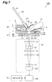
- Fig. 7 is a schematic structural diagram of a
noninvasive optical bioinstrumentation device
constituting a fourth embodiment of the present invention;
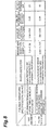
- Fig. 8 is a table which shows the measurement results
for blood levels obtained by means of the noninvasive
optical bioinstrumentation devices of the first embodiment
and fourth embodiment;
- Fig. 9 is a schematic structural diagram of a
noninvasive optical bioinstrumentation device
constituting a fifth embodiment of the present invention;
- Fig. 10 is a schematic structural diagram of a
noninvasive optical bioinstrumentation device
constituting a sixth embodiment of the present invention;
- Fig. 11 is a schematic structural diagram of a
noninvasive optical bioinstrumentation device
constituting a seventh embodiment of the present invention;
- Fig. 12 is a schematic structural diagram of a
noninvasive optical bioinstrumentation device
constituting an eighth embodiment of the present invention;
- Fig. 13 is a schematic structural diagram of a
noninvasive optical bioinstrumentation device
constituting a ninth embodiment of the present invention;
- Fig. 14 is a schematic structural diagram of a
noninvasive optical bioinstrumentation device
constituting a tenth embodiment of the present invention;
- Fig. 15 is a schematic structural diagram of a
noninvasive optical bioinstrumentation device
constituting an eleventh embodiment of the present
invention;
- Fig. 16 is a schematic structural diagram of a
noninvasive optical bioinstrumentation device
constituting a twelfth embodiment of the present invention;
- Fig. 17A is an overall schematic structural diagram
of a noninvasive optical bioinstrumentation device
constituting a thirteenth embodiment of the present
invention;
- Fig. 17B is a front view of the circular turret shown
in Fig. 17A;
- Fig. 18 is a schematic structural diagram of a
noninvasive optical bioinstrumentation device
constituting a fourteenth embodiment of the present
invention;
- Fig. 19 is a schematic structural diagram showing a
noninvasive optical bioinstrumentation device which
mounts the measurement site holder of a noninvasive optical
bioinstrumentation device constituting a fifteenth
embodiment of the present invention;
- Fig. 20A is a plan view of a device shown with the
measurement site holding device mounting the measurement
site holder shown in Fig. 19 extracted;
- Fig. 20B is a sectional view along line XX-XX of the
device shown in Fig. 20A;
- Fig. 21 is a graph which shows the variation over time
of blood sugar levels obtained by blood collection
following ingestion of a saccharine liquid;
- Fig. 22 is a graph which shows the correlation between
analysis values obtained by blood collection and predicted
values according to the near infrared spectrum;
- Fig. 23A is a plan view of another measurement site
holding device mounting the measurement site holder of the
noninvasive optical bioinstrumentation device of the
fifteenth embodiment;
- Fig. 23B is a sectional view along line XXIII-XXIII
of the device shown in Fig. 23A;
- Fig. 24 is a sectional view of a measurement site
holding device mounting the measurement site holder of a
noninvasive optical bioinstrumentation device
constituting a sixteenth embodiment of the present
invention;
- Fig. 25A is a structural diagram of a noninvasive
optical bioinstrumentation device constituting a
seventeenth embodiment of the present invention;
- Fig. 25B is a front view of the circular turret 48
used as the light adjustment means in the noninvasive
optical bioinstrumentation device;
- Fig. 26 is a perspective view of the measurement site
holder 3;
- Fig. 27 is a sectional view along line XXVII-XXVII
of the measurement site holder 3 shown in Fig. 26; and
- Fig. 28 is a partial perspective view of the
measurement site holder 3.
-
BEST MODE FOR CARRYING OUT THE INVENTION
-
Embodiments of the present invention will be
described below with reference to the attached figures.
(First Embodiment)
-
Fig. 1 is a schematic structural diagram which shows
a noninvasive optical bioinstrumentation device
constituting a first embodiment of the present invention.
Fig. 2A is a plan view of a measurement site holding device
equipped with the measurement site holder shown in Fig.
1, and Fig. 2B is a sectional view along line II-II of the
device shown in Fig. 2A.
-
In the noninvasive optical bioinstrumentation device
50 of the present embodiment, as is shown in Fig. 1, the
living-body measurement site is a finger (finger tip) 10.
This noninvasive optical bioinstrumentation device 50
comprises a measurement site holder 3 which has a main body
part 3a in which the finger 10 is placed, a measurement
site holding device 51 in which this measurement site holder
3 is mounted, and which is equipped with a photo-detector
(photo-detection system) 5 that detects the light that is
transmitted through the finger 10 placed in the main body
part 3a of the abovementioned measurement site holder 3,
a Fourier transform near infrared spectroscopic analyzer
9 in which light from a light source 91 is emitted to the
outside via a Michaelson interferometer 92 so that the
finger 10 placed inside the main body part 3a of the
measurement site holder 3 is illuminated, and a near
infrared spectrum is obtained by subjecting a near infrared
interferogram detected by the photo-detector 5 on the basis
of the light transmitted through the finger 10 to a Fourier
transform using a computer system part 94, and a computer
60 which prepares a working curve on the basis of this near
infrared spectrum, and predicts blood sugar levels on the
basis of this working curve.
-
As is shown in Figs. 2A and 2B, the measurement site
holding device 51 is equipped with a base 1 which has a
rectangular shape and which is attached to the main body
side of the noninvasive optical bioinstrumentation device
50. As is shown in Fig. 2B, an opening part 1a which passes
vertically through the base 1 is formed in the approximate
center of this base 1, and a photo-detector 5 is mounted
inside this opening part 1a. This photo-detector 5 is
disposed so that the photo-detection part is visible from
the upper side of the opening part 1a.
-
As is shown in Fig. 2B, a rectangular base plate 4
which holds the abovementioned measurement site holder 3
on the upper part of this base plate 4 is detachably mounted
on the upper surface of the base 1. The base 1 is disposed
in the light path along which light is incident on the
photo-detection system 5 from the light illuminating system
91, 92, 93, and if the measurement site holder 3 is installed
on the base 1, then the finger (measurement site) 10 placed
inside the measurement site holder 3 will be positioned
in the abovementioned light path.
-
The base 1 has a rectangular groove 6 (in the upper
surface of the base 1) which is formed so that the base
plate 4 can be inserted from the horizontal direction, a
U-shaped or C-shaped base plate supporting part 2 which
surrounds the upper part of the closed side (the left side
in Fig. 2B) of the groove 6 on three sides, an opening part
7 which passes vertically through the base 1 in a specified
position located further toward the open side of the
abovementioned groove 6 than an opening part 1a formed in
the groove 6, a spherical stopper 7a which is disposed
inside this opening part 7, and a spring 7b which drives
this stopper 7a upward. This base 1 is constructed in such
a manner that when the base plate 4 is inserted along the
groove 4 from the open side of the groove 6 so that the
base plate 4 is caused to abut the close-side end portion
of the groove 6, the spherical stopper 7a is engaged in
an opening part 4a formed in the base plate 4, so that the
base plate 4 is positioned on the base 1, and is always
fixed in the same position; furthermore, the base plate
4, i. e., the measurement site holder 3, is detachably
mounted on the upper surface of the base 1.
-
The main body part 3a of the measurement site holder
3 mounted on the upper part of this base plate 4 constitutes
the characterizing feature of the present embodiment.
This main body part 3a is manufactured as a negative
impression of the finger of each individual patient (the
method of manufacture will be described later). As is
shown in Fig. 1, an opening part 31 used for the incidence
of light is formed in a position that corresponds to a
specified position (the nail surface in the present
embodiment) on the finger 10 that is placed on the main
body pat 3a of the measurement site holder 3, and an opening
part 32 used for light detection (light emission) is formed
in a position corresponding to the opposite surface of the
finger 10 from the nail surface; furthermore, a nail
opening part 33 is formed in position corresponding to the
direction of extension of the nail of the finger 10.
-
The opening part 31 used for illumination with light
is an opening part which is positioned on the light path
from the Michaelson interferometer 92 of the Fourier
transform near infrared spectroscopic analyzer 9 when the
base plate 4 on which the measurement site holder 3 is
installed is mounted on the base 1, and the finger 10 is
placed inside the main body part (main body part of the
measurement site holder) 3a of the measurement site holder
3; this opening part 31 conducts light that is focused by
a focusing lens 93 positioned between the Michaelson
interferometer 92 and the light-illumination opening part
31 into the interior of the main body part 3a of the
measurement site holder 3, and makes it possible to
illuminate a specified position on the finger 10. The
light-detection opening part 32 is an opening part which
is positioned coaxially with the opening part 1a in which
the photo-detection part of the photo-detector 5 is visible,
and which makes it possible to guide the transmitted light
that passes through the finger 10 to the photo-detector
5.
-
Next, the method used to manufacture the measurement
site holder 3 (main body part 3a) in which the
abovementioned light-illumination opening part 31,
light-detection opening part 32 and nail opening part 33
are formed in a negative impression will be described.
First, a material which has sufficient fluidity to allow
application as a coating to the surface of the finger 10,
or which softens at a relatively low temperature and
requires little stress to be deformed when softened, and
which furthermore hardens in a short time and has sufficient
strength with a high dimensional stability during hardening,
and is optically stable over a long period of time, is
prepared as the molding material for the negative
impression. In concrete terms, for example, impression
materials or resins that polymerize at ordinary
temperatures, which are used in dental treatments, and
thermoplastic resins or the like which are used in plastic
surgery and radiation therapy, are desirable. Here, a
resin that polymerizes at ordinary temperatures will be
used in the present embodiment.
-
Furthermore, in a state in which the surface of the
finger 10 is thinly coated with a peeling agent such as
vaseline or the like, and (for example) the finger 10 is
held in the air so that there is no deformation in the shape
of the finger 10, the surface of the finger 10 is
brush-coated with an ordinary-temperature polymerizing
resin using a brush coating method. Here, for example,
brush coating is performed as far as the vicinity of the
second joint from the finger tip (proximal interphalangeal
joint) . In this case, in order to alleviate the burden on
the patient, it is desirable to us GC Unifast Trad
(manufactured by GC Corp.) or the like, which has a short
hardening time of 3 minutes. Furthermore, following the
completion of brush coating, the finger 10 is allowed to
stand "as is" in a fixed state for approximately 3 minutes.
Afterward, the finger 10 is removed, and the
ordinary-temperature polymerizing resin is sufficiently
hardened so that a negative impression of the finger 10
is obtained. As was described above, such a negative
impression is prepared for each individual patient.
Accordingly, the respective negative impressions match the
finger shapes of the individual patients.
-
Once a negative impression has thus been obtained,
the abovementioned light-illumination opening part 31 and
light-detection opening part 32 are opened in the negative
impression. Here, since the nail of the finger grows as
time passes, the elongated nail is a factor that alters
the placement position of the finger 10 with respect to
the negative impression (i. e., a factor that lowers the
positioning precision of the finger 10 with respect to the
negative impression). Accordingly, the abovementioned
nail opening part 33 is opened in the negative impression
along with the light-illumination opening part 31 and
light-detection opening part 32. Furthermore, the inside
contact surface of the negative impression that contacts
the finger 10 is coated with (for example) a delustering
black coating material or the like as a coating material
that absorbs light of the measurement wavelength, thus
producing the measurement site holder 3 shown in Figs. 1,
2A and 2B.
-
Next, the operation of a noninvasive optical
bioinstrumentation device 50 equipped with a measurement
site holder 3 constructed as described above will be
described. First, the base plate 4 holding the measurement
site holder (individual patient measurement site holder)
3 manufactured for the patient that is the object of
measurement is mounted on the base 1. In this case, the
measurement site holder 3 on the base plate 4 is positioned
and mounted on the base 1 with high precision by means of
the abovementioned groove 6, base plate supporting part
2, stopper 7a and the like.
-
Next, the patient inserts the finger 10 used in the
preparation of the negative impression into the measurement
site holder 3. In this case, since the measurement site
holder 3 was manufactured as a negative impression of the
finger for each individual patient, the measurement site
holder 3 matches the finger shape of the individual patient.
Accordingly, the finger 10 is positioned with high
precision, and the finger 10 uniformly contacts this
measurement site holder 3. In this case, furthermore, even
if the nail grows, this nail protrudes from the nail opening
part 33, so that there is no interference with the
high-precision positioning of the finger 10.
-
Next, in the measurement operation, light from the
light source 91 is caused to enter the measurement site
holder 3 via the Michaelson interferometer 92, focusing
lens 93 and light-illumination opening part 31, so that
a specified position on the finger 10 is illuminated. In
this case, as was described above, the finger 10 is
positioned with a high degree of precision, and contacts
the measurement site holder 3 in a uniform manner. In
addition, the measurement site holder 3 is positioned with
a high degree of precision relative to the base 1.
Accordingly, the incident light always illuminates
substantially the same position on the finger 10, which
shows no great variation in shape, so that the light that
is transmitted through this finger 10 always passes through
substantially the same position, and is received by the
photo-detector 5 via the light-detection opening part 32.
-
The signal produced by a photo-electric conversion
from this photo-detector 5 is input into the computer system
part 94 so that a near infrared spectrum is obtained. This
near infrared spectral information and blood sugar levels
obtained by blood collection performed at the same time
as the measurement of the near infrared spectrum are input
into the computer 60, and a working curve for blood sugar
levels is prepared on the basis of these respective types
of information. This computer 60 stores this working curve
as a data table in internal or external memory means, and
reads out this working curve at the time of measurement
of blood sugar levels, so that blood sugar levels are
obtained by comparing the measured near infrared spectrum
with this working curve.
-
Furthermore, in cases where the blood sugar levels
of another patient are to be measured using this noninvasive
optical bioinstrumentation device 50, the base plate 4
holding the abovementioned measurement site holder 3 is
removed, and a base plate 4 holding a different measurement
site holder 3 that has been manufactured for this other
patient (and that matches the finger shape of this other
patient) is mounted on the base 1, and measurements are
performed. Furthermore, the working curves prepared by
the computer 60 are prepared and stored in memory for each
individual patient.
-
Thus, in the present embodiment, since the
measurement site holder 3 is constructed using a negative
impression of the finger for each individual patient, the
measurement site holder 3 matches the shape of the finger
of each patient. Accordingly, when the finger 10 is placed
in the measurement site holder 3 at the time of light
detection, the finger 10 is positioned with a high degree
of precision, so that shifting of the light path in the
finger 10 can be more or less prevented. Consequently,
variation in the measured values caused by the non-uniform
distribution of components in the living body can be
minimized; furthermore, extremely fine variations in the
shape of the finger 10 can be more or less prevented, so
that variation in the measured values caused by variations
in the light path length that accompany variations in the
shape of the finger 10, and variations in blood flow that
accompany fine differences in the contact pressure, can
be minimized. Accordingly, blood sugar levels can be
quantitatively measured with a high degree of precision.
-
Furthermore, since the measurement site holder 3 has
a detachable structure, the same noninvasive optical
bioinstrumentation device 50 can be shared by numerous
patients by mounting measurement site holders 3 that were
prepared for the individual patients and that match the
fingers of the individual patients on this device 50.
Accordingly, the blood sugar levels of numerous patients
can be quantitatively measured using the same device 50.
-
Furthermore, since the measurement site holder 3 is
equipped with a light-illumination opening part 31 that
makes it possible to illuminate the finger 10 with light,
and a light-detection opening part 32 that makes it possible
to guide transmitted light from the finger 10 to a
photo-detector 5, the position at which light is incident
on the finger 10 and the position at which light is emitted
from the finger 10 can be accurately determined, so that
variation in the measured values can be greatly reduced.
Accordingly, blood sugar levels can be measured with much
higher precision.
-
Furthermore, since the inside of the measurement site
holder 3 is coated with a coating material that absorbs
light of the measurement wavelength, minute variations in
the length of the light path inside the living body caused
by the reflection of light at the contact interface between
the measurement site holder 3 and finger 10 can be prevented,
so that variation in the measured values can be greatly
reduced. As a result, blood sugar levels can be measured
with much higher precision. Furthermore, the measurement
site holder 3 may also be equipped with a main body part
3a which consists of a resin containing a pigment or dye
that absorbs light of the measurement wavelength, and which
contacts the finger (measurement site) 10.
-
Here, in order to confirm the abovementioned effects
of the measurement site holder 3, the present inventors
performed the experiment described below using a system
in which the abovementioned measurement site holder 3 was
employed in the noninvasive optical bioinstrumentation
device 50 (the noninvasive optical bioinstrumentation
device 50 of the present embodiment shown in Fig. 1), and
a system in which a universally known finger holder was
employed instead of this measurement site holder 3. In
this way, the inventors evaluated the precision of both
systems (the measurement site holder 3 and finger holder).
-
The acceleration pulse wave sensor AS-120 of the
Precaregraph AGP-200 manufactured by Misawa Home Institute
of Research Development Co. Ltd. was used as a finger holder.
A finger holder prepared by removing the light-emitting
element and photo-detector of this finger holder, and
respectively forming a light-illumination opening part and
light-detection opening part in these positions, was
fastened to the base plate 4 instead of the measurement
site holder 3.
-
Furthermore, in this experiment, a Spectrum 2000 FTIR
manufactured by Perkin-Elmer Inc. was used as the Fourier
transform near infrared spectroscopic analyzer 9, and an
InGaAs-PIN photodiode (G5832-05 manufactured by Hamamatsu
Photonics K.K.) was used as the photo-detector 5. The
measurement wavelength range was set at 1.0 to 1.38 µm.
-
Then, after fasting for approximately 12 hours, each
patient was caused to ingest a saccharine liquid (Trelan
G75 manufactured by Shimizu Pharmaceutical Co. Ltd.,
glucose content 75 g) . Blood was collected by pricking a
finger tip on the left hand before ingestion of the
saccharine liquid, and every 10 minutes up to 2 hours
following the ingestion of the saccharine liquid, and blood
sugar levels were measured (analysis values according to
a conventional method) using a compact electrode type blood
sugar measuring device (Antosense II manufactured by
Bayer-Sankyo(Bayer Medical Ltd.)). Meanwhile,
measurements of the near infrared spectrum by means of the
measurement site holder 3 and finger holder were performed
using the right hand at the time that blood was collected
from the abovementioned finger tip of the left hand. The
days on which measurements were performed using the
measurement site holder 3 and the days on which measurements
were performed using the finger holder were different days .
-
The preparation of working curves was accomplished
using a partial least squares (PLS) regression analysis,
with the blood sugar level obtained by means of the
abovementioned blood collection used as the objective
variable, and the near infrared spectrum measured at the
same time as blood collection used as the descriptive
variable. The predicted values of blood sugar levels
according to the near infrared spectrum were calculated
using the working curves thus prepared. The cross
validation method was used in order to evaluate the
precision of the working curves.
-
Fig. 3 is a graph which compares changes over time
in the blood sugar levels following the ingestion of the
abovementioned saccharine liquid that were measured using
this measurement site holder with those that were measured
using the abovementioned universally known finger holder.
As is indicated by the black circles in Fig. 3, the blood
sugar levels that were measured for patients when the
measurement site holder 3 was used fluctuated over a range
of 114 to 244 mg/dl. Furthermore, the squares indicate the
blood sugar levels that were measured for patients when
the finger holder was used.
-
Fig. 4A is a graph which shows the near infrared
spectrum (absorption characteristics) of the finger tips
measured using the measurement site holder of the present
embodiment. Fig. 4B is a graph which shows the near
infrared spectrum (absorption characteristics) of the
finger tips measured using the abovementioned ordinary
finger holder. The fluctuation in the spectrum seen in
individual measurements of the near infrared spectrum
measured using the measurement site holder 3 (see Fig. 4A)
is conspicuously smaller than the fluctuation in the
spectrum seen in individual measurements of the near
infrared spectrum measuring using the finger holder (see
Fig. 4B) .
-
As a result of PLS regression analysis using cross
validation, the correlation coefficient between the
analysis values obtained by blood collection and the
predicted values according to the near infrared spectrum
was 0.85, and the root mean square error of prediction
(RMSEP) was 23 mg/dl, in cases where the measurement site
holder 3 was used. On the other hand, when the finger holder
was used, the correlation coefficient between the analysis
values obtained by blood collection and the predicted
values according to the near infrared spectrum was 0.57,
and the root mean square error of prediction was 41 mg/dl.
-
Specifically, it was confirmed that blood sugar
levels can be quantitatively measured with a high degree
of precision by using the measurement site holder 3 of the
present embodiment.
(Second Embodiment)
-
Fig. 5A is a plan view of the measurement site holding
device of a noninvasive optical bioinstrumentation device
constituting a second embodiment of the present invention.
Fig. 5B is a sectional view along line V-V of the device
shown in Fig. 5A.
-
This second embodiment differs from the first
embodiment in that this embodiment is constructed so that
the finger 10 is illuminated by guiding the illuminating
light with an optical fiber 82. Specifically, the
measurement site holding device 52 of this second
embodiment is further equipped with an optical fiber
supporting base 8 which is disposed on the end portion of
the base 1 located on the opposite side from the side where
the base plate 4 is inserted, and which has a shape that
extends from this end portion and covers the
light-illumination opening part 31 of the measurement site
holder 3 from above. Furthermore, the measurement site
holding device 52 is also equipped with a guide 81 which
is located on this optical fiber supporting base 8 in a
position corresponding to the light-illumination opening
part 31 of the abovementioned measurement site holder 3,
and which has an inclined shape that is coaxial with the
abovementioned light-illumination opening part 31. The
tip end portion of the optical fiber 82 that is used to
illuminate the finger 10 is inserted into this guide 81
so that the optical fiber 82 can slide.
-
In the measurement site holding device 52 constructed
as described above, the emitting end 83 of the optical fiber
82 can always be accurately positioned inside the
light-illumination opening part 31 by sliding the optical
fiber 82, even if a measurement site holder 3 which has
a different size (because or the size of the patient's
finger) is mounted on the base 1 and the finger 10 is placed
in this measurement site holder 3.
-
Accordingly, in this second embodiment, in addition
to the effects of the first embodiment, variation in the
measured values is greatly reduced regardless of the size
of the patient's finger, so that blood sugar levels can
be quantitatively measured with an even higher degree of
precision.
-
Furthermore, it would also be possible to install an
optical fiber that guides the light transmitted through
the finger 10 to the photo-detection system in the
installation position of the photo-detector 5.
Furthermore, in cases where optical fibers are thus used
in both locations, the light-illumination opening part 31
and the optical fiber on the side of this light-illumination
opening part 31 can also be used for light detection, and
the light-detection opening part 32 and the optical fiber
on the side of this light-detection opening part 32 can
also be used for light illumination.
(Third Embodiment)
-
Fig. 6 is a sectional view which shows the measurement
site holding device of a noninvasive optical
bioinstrumentation device constituting a third embodiment
of the present invention.
-
This third embodiment differs from the first
embodiment in the following respects: specifically, the
finger 10 is illuminated by guiding the illuminating light
with an optical fiber 82a, and the light transmitted through
the finger 10 is guided into the photo-detection system
by an optical fiber 82b; furthermore, the device is
constructed so that these light transmitting and receiving
optical fibers 82a and 82b are detachable from the
measurement site holder 3.
-
Specifically, the measurement site holding device 53
of this third embodiment is equipped with an optical fiber
receiving fitting 85a which has a tubular shape and which
surrounds the light-illumination opening part 31, and an
optical fiber receiving fitting 85b which has a tubular
shape and which surrounds the light-detection opening part
32, on the outer surface of the measurement site holder
3. Furthermore, the measurement site holding device 53 is
equipped with an optical fiber retaining fitting 84a which
mounts the optical fiber 82a that is used to illuminate
the finger 10, and which is detachably mounted on the
optical fiber receiving fitting 85a, and an optical fiber
retaining fitting 84b which mounts the optical fiber 82b
that is used to guide the light transmitted through the
finger 10 to the photo-detection system, and which is
detachably mounted on the optical fiber receiving fitting
85b.
-
Various constructions may be used as concrete
constructions that allow these optical fiber retaining
fittings 84a and 84b to be respectively attached to or
detached from the optical fiber receiving fittings 85a and
85b; for example, screws that are screw-engaged with each
other or grooves and protruding parts that engage with each
other may be used.
-
Furthermore, the device is constructed so that the
light-illumination opening part 31, optical fiber
receiving fitting 85a, optical fiber retaining fitting 84a
and optical fiber 82a are coaxially positioned, and so that
the light-detection opening part 32, optical fiber
receiving fitting 85b, optical fiber retaining fitting 84b
and optical fiber 82b are coaxially positioned.
Furthermore, the optical fiber receiving fittings 85a and
85b, and the optical fiber retaining fittings 84a and 84b,
are constructed so that these respective fittings have the
same shape.
-
It goes without saying that the same effects as those
obtained in the first embodiment can also be obtained in
this construction; in addition, since the transmission
and reception of light to and from the finger 10 are
performed using optical fibers 82a and 82b, measurements
can be performed on patients in locations that are separated
from the main body side of the noninvasive optical
bioinstrumentation device 50.
-
Furthermore, a construction may also be used in which
a photo-detector which has a housing that is detachable
from the measurement site holder 3 is mounted on the
light-detection opening part 32 of this measurement site
holder 3, so that light can be detected by this
photo-detector via the light-detection opening part 32.
-
Furthermore, a construction may also be used in which
a light-emitting element which has a housing that is
detachable from the measurement site holder 3 is mounted
on the light-illumination opening part 31 of this
measurement site holder 3, so that light illumination can
be performed by this light-emitting element via the
light-illumination opening part 31.
-
Furthermore, as in the second embodiment, the
light-illumination opening part 31 and the optical fiber
82a on the side of this light-illumination opening part
31 can also be used for light detection, and the
light-detection opening part 32 and the optical fiber 82b
on the side of this light-detection opening part 32 can
also be used for light illumination.
(Fourth Embodiment)
-
Fig. 7 is a schematic structural diagram which
illustrates a noninvasive optical bioinstrumentation
device 100 constituting a fourth embodiment of the present
invention. The noninvasive optical bioinstrumentation
device 100 of this embodiment differs from the noninvasive
optical bioinstrumentation device of the second embodiment
in that a birefringent interferometer (photo-detection
system) 70 is installed instead of the Michaelson
interferometer 92 and photo-detector 5, and a computer 160
which has the functions of both the computer system part
94 and computer 60 is installed instead of these two parts.
Furthermore, a sliding type turret 47 is installed as light
adjustment means between the birefringent interferometer
70 and the light-detection opening part 32 side of the
measurement site holding device 52.
-
The birefringent interferometer 70 is equipped with
a polarizer 72 which polarizes the transmitted light that
is transmitted through the finger 10, a Savart plate
(polarized light splitting birefringent element) 73 which
splits the transmitted light polarized by the polarizer
72 into polarized light with mutually perpendicular
vibrational planes, thus producing parallel split light
beams, an analyzer 74 which polarizes the split light split
by the Savart plate 73, a converging lens (converging means)
193 and cylindrical lens 77 which cause the light polarized
by the analyzer 74 to converge, thus forming an
interferogram, and a solid state imaging element
(photo-detector) 105 which detects the interferogram thus
formed. This birefringent interferometer 70 acquires
interferograms by causing interference of the transmitted
light from the finger 10.
-
The computer 160 calculates the spectrum and
concentrations of components in the living body on the basis
of the interferograms acquired by the birefringent
interferometer 70.
-
The sliding type turret 47 is disposed on the
light-detection opening part 32 side of the measurement
site holding device 52, and is equipped with a sliding plate
46 which consists of a light-blocking plate 40, aperture
plate 41 and light-reducing plate 42 that are respectively
separated from each other, and which can slide so that these
respective plates coincide with the light-detection
opening part 32, and a sliding plate guide 45 which holds
the sliding plate 46 so that this sliding plate 46 can slide.
This sliding type turret 47 reduces or narrows down light
on the light path 49 of the transmitted light from the finger
10 by positioning the respective plates in this light path
49.
-
Next, the operation of the noninvasive optical
bioinstrumentation device 100 of the present embodiment
will be described.
-
First, the base plate 4 holding the measurement site
holder (measurement site holder for the individual patient)
3 that has been manufactured for the patient that is the
object of measurement in the same manner as in the first
embodiment is mounted on the base 1. In this case, the
measurement site holder 3 on the base plate 4 is mounted
while being positioned with a high degree of precision with
respect to the base 1 by means of the abovementioned groove
6, base plate supporting part 2, stopper 7a and the like.
-
Next, in a state in which the finger 10 has not been
inserted into the measurement site holder 3, the sliding
plate 46 of the sliding type turret 47 is caused to slide
so that the light-blocking plate 40 is aligned with the
light path 49. Then, in this state, background light data
is acquired by means of the solid state imaging element
105.
-
Next, the polarization directions of the polarizer
72 and analyzer 74 of the birefringent interferometer 70
are set parallel to each other, and the sliding plate 46
is caused to slide so that the aperture plate 41 is aligned
with the light path 49, and light is emitted from the light
source 91. This light emitted from the light source passes
through the optical fiber 82, light-illumination opening
part 31 and interior of the measurement site holder 3, and
is emitted from the light-detection opening part 32. The
light is then narrowped down by the aperture plate 41 of
the sliding type turret 47, and enters the birefringent
interferometer 70.
-
The direction of polarization of the light that has
entered the birefringent interferometer 70 is adjusted by
the polarizer 72, and is split into two parallel light beams
that are polarized in mutually perpendicular directions
by the Savart plate 73. The directions of polarization of
the split light beams are then again adjusted by the
analyzer 74, so that the light beams are caused to interfere
with each other. The interfering light is focused as an
image on the solid state imaging element 105 by the
converging lens 193 and cylindrical lens 77, so that a
spatial interferogram is formed. The interferogram thus
formed is detected by the solid state imaging element 105,
and is acquired by the computer 160.
-
Next, the directions of polarization of the polarizer
72 and analyzer 74 of the birefringent interferometer 70
are set perpendicular to each other, and another
interferogram is similarly acquired.
-
Then, the difference between the two spatial
interferograms, i. e., the interferogram obtained with the
directions of polarization of the polarizer 72 and analyzer
74 of the birefringent interferometer 70 set parallel to
each other, and the interferogram obtained with these
directions of polarization set perpendicular to each other,
is taken by the computer 160. These two interferograms
share a background component that is characteristic of the
device, but have spatial interferogram components based
on the transmitted light that are in a state in which light
and dark are inverted.
-
Accordingly, if the difference between the two
interferograms is taken, the background component is
eliminated, and the spatial interferogram intensity based
on the light from the measurement site holder 3 is doubled,
so that the S/N ratio of the interferogram can be improved.
Furthermore, the interferogram whose S/N ratio has thus
been improved is analyzed by the computer 160 and acquired
as reference data.
-
Next, the patient inserts the finger 10 used in the
preparation of the negative impression into the measurement
site holder 3. Furthermore, the sliding plate 46 of the
sliding type turret 47 is caused to slide so that a state
is obtained in which nothing blocks the light path 49, and
light from the light source 91 is caused to be incident
on a specified position of the finger 10 via the optical
fiber 82. The transmitted light that passes through the
finger enters the birefringent interferometer 70 via the
light-detection opening part 32, and an interferogram is
formed on the solid state imaging element 105 by the same
operation as that described above. This interferogram is
detected by the solid state imaging element 105, and is
acquired by the computer 160.
-
In this case, in order to maximize the S/N ratio of
the detected light detected by the solid state imaging
element 105, the amount of light is adjusted if necessary
by causing the sliding plate 46 of the sliding type turret
47 to slide so that the light-reducing plate 42 is aligned
with the light path 49. Furthermore, in this case as well,
two interferograms, i. e., an interferogram obtained with
the directions of polarization of the polarizer 72 and
analyzer 74 of the birefringent interferometer 70 set
perpendicular to each other, and an interferogram obtained
with these directions of polarization set parallel to each
other, are acquired in the same manner as described above,
and the difference is taken so that an interferogram based
on the transmitted light is acquired with an improved S/N
ratio.
-
Then, the computer 160 acquires an interferogram
based on the transmitted light, a reference spectrum
obtained beforehand and a near infrared spectrum based on
the background light data, and prepares a working curve
for the blood sugar levels on the basis of this near infrared
spectral data and the blood sugar levels obtained by blood
collection performed at the same time as the measurement
of the near infrared spectrum. Then, as in the first
embodiment, the computer 160 obtains blood sugar levels
by comparing the measured near infrared spectrum with this
working curve.
-
Thus, the noninvasive optical bioinstrumentation
device 100 of the present embodiment makes it possible to
obtain the same effects as those of the noninvasive optical
bioinstrumentation device of the second embodiment;
furthermore, since interferograms are obtained by
polarizing and causing interference of the transmitted
light by means of a birefringent interferometer 70, the
required construction is simpler than that of the
noninvasive optical bioinstrumentation device of the
second embodiment using a Michelson interferometer 92,
since mirror driving or control mechanism, and no
mechanical driving parts for a laser interferometer or the
like used for sampling designation of the main
interferometer. Accordingly, a reduction in size and
weight and an improvement of the vibration resistance can
be achieved.
-
Furthermore, as a result, a noninvasive optical
bioinstrumentation device 100 which offers high
portability and high precision can be obtained at a low
cost.
-
Furthermore, by taking the difference between an
interferogram obtained with the directions of polarization
of the polarizer 72 and analyzer 74 set perpendicular to
each other and an interferogram obtained with the
directions of polarization of the polarizer 72 and analyzer
74 set parallel to each other, it is possible to eliminate
the background component and double the intensity of the
interferogram, so that the S/N ratio can be increased even
further. Accordingly, blood sugar levels or the like can
be quantitatively determined with an even higher degree
of precision.
-
Furthermore, since a sliding type turret 47 is
installed so that the light that is incident on the
birefringent interferometer can easily be narrowped down
or reduced, interferograms with a high S/N ratio can be
acquired.
-
Furthermore, since spatial interferograms are caused
to converge on the solid state imaging element 105 by means
of a cylindrical lens 77, the spatial interferogram
intensity can be further increased, so that the S/N ratio
is improved to an even greater degree.
-
Here, in order to confirm the abovementioned effects
of the noninvasive optical bioinstrumentation device 100
of the present embodiment, the present inventors measured
the blood sugar levels of patients under the same conditions
as in the first embodiment, using the procedure described
above.
-
In the experiment, a tungsten halogen lamp (8 W) was
used as the light source 91, infrared glass polarizing
elements (1310HC manufactured by Corning Co.) were used
as the polarizer 72 and analyzer 74, and a plate made of
titanium oxide was used as the Savart plate 73.
Furthermore, an InGaAs linear image sensor (G7231-256
manufactured by Hamamatsu Photonics K.K.), which is a
multi-channel photo-detector, was used as the solid state
imaging element 105, and the measurement wavelength range
was set at 0.95 to 1.345 µm.
-
The results are compared with those obtained for the
first embodiment in Fig. 8. The blood sugar levels
fluctuated over a range of 109 to 225 mg/dl. Furthermore,
when a PLS regression analysis was performed, the
correlation coefficient between the measured blood sugar
levels obtained by blood collection and the values
predicted by the noninvasive optical bioinstrumentation
device 100 of the present embodiment was 0.94, and the root
mean square error of prediction (RMSEP) was 15 mg/dl. It
was thus confirmed that the noninvasive optical
bioinstrumentation device 100 of the fourth embodiment
equipped with a birefringent interferometer 70 is superior
to the noninvasive optical bioinstrumentation device 50
of the first embodiment equipped with a Michelson
interferometer both in terms of the correlation coefficient
and in terms of the root mean square error of prediction,
so that the determinability of blood sugar levels is
improved even further.
(Fifth Embodiment)
-
Next, a fifth embodiment of the present invention
will be described with reference to Fig. 9. This
embodiment differs from the fourth embodiment in that an
optical fiber 182 which conducts the light that has passed
through the sliding type turret 47 to the birefringent
interferometer 70 is provided. The same effects as those
obtained in the fourth embodiment can be obtained in this
embodiment as well; furthermore, measurement site holding
device 52 can be installed in a location that is separated
from the birefringent interferometer 70.
(Sixth Embodiment)
-
Next, a sixth embodiment of the present invention
will be described with reference to Fig. 10. This
embodiment differs from the fifth embodiment in that the
sliding type turret 47 is installed on the side of the
birefringent interferometer 70 rather than on the side of
the measurement site holding device 52, so that the light
emitted from the light-detection opening part 32 of the
measurement site holding device 52 is incident on the
birefringent interferometer 70 after being incident on the
sliding type turret 47 via the optical fiber 182. The same
effects as those obtained in the fifth embodiment can also
be obtained by means of this embodiment.
(Seventh Embodiment)
-
Next, a seventh embodiment of the present invention
will be described with reference to Fig. 11. This
embodiment differs from the fifth embodiment in that the
light source 91 is installed in the measurement site holding
device 52 so that the illuminating light from the light
source 91 is caused to illuminate the finger 10 directly.
It goes without saying that the same effects as those
obtained in the fifth embodiment can also be obtained by
means of this embodiment.
(Eighth Embodiment)
-
Next, an eighth embodiment of the present invention
will be described with reference to Fig. 12. This
embodiment differs from the seventh embodiment in that the
sliding type turret 47 is installed on the side of the
birefringent interferometer 70 so that the light emitted
from the light-detection opening part 32 of the measurement
site holding device 52 is incident on the birefringent
interferometer 70 after being incident on the sliding type
turret 47 via the optical fiber 182. The same effects as
those obtained in the seventh embodiment can also be
obtained by means of this embodiment.
(Ninth Embodiment)
-
Next, a ninth embodiment of the present invention
will be described with reference to Fig. 13. This
embodiment differs from the fifth embodiment in that an
optical fiber 82 which conducts the illuminating light from
the light source 91 to the finger 10 is connected to the
side of the light-detection opening part 32 in order to
cause diffused and reflected light from the finger 10 to
be incident on the birefringent interferometer 70. Here,
the light-detection opening part 32 is also used as a
light-illumination opening part by means of the optical
fiber 82. As a result, the illuminating light that is
emitted from the light source 91 is caused to illuminate
the finger 10 from the light-detection opening part 32 via
the optical fiber 82, and the diffused and reflected light
from the finger 10 is incident on the birefringent
interferometer 70 via the light-detection opening part 32,
sliding type turret 47 and optical fiber 182. Accordingly,
the same effects as those obtained in the fifth embodiment
can be obtained. Furthermore, it would also be possible
to form a separate light-illumination opening part on the
light-detection opening part 32 side of the measurement
site holding device 52 (i.e., the lower side in the figure) ,
and to connect the optical fiber 82 to this
light-illumination opening part.
(Tenth Embodiment)
-
Next, a tenth embodiment of the present invention
will be described with reference to Fig. 14. This
embodiment differs from the ninth embodiment in that the
sliding type turret 47 is installed on the side of the
birefringent interferometer 70, so that the diffused and
reflected light emitted from the light-detection opening
part 32 of the measurement site holding device 52 is
incident on the birefringent interferometer 70 after being
incident on the sliding type turret 47 via the optical fiber
182. The same effects as those obtained in the ninth
embodiment can also be obtained by means of this embodiment.
(Eleventh Embodiment)
-
Next, an eleventh embodiment of the present invention
will be described with reference to Fig. 15. This
embodiment differs from the ninth embodiment in that the
light source 91 is installed on the light-detection opening
part 32 side of the measurement site holding device 52,
so that the illuminating light from the light source 91
is caused to illuminate the finger 10 directly. The same
effects as those obtained in the ninth embodiment can also
be obtained by means of this embodiment.
(Twelfth Embodiment)
-
Next, a twelfth embodiment of the present invention
will be described with reference to Fig. 16. This
embodiment differs from the eleventh embodiment in that
the sliding type turret 47 is installed on the side of the
birefringent interferometer 70 rather than on the side of
the measurement site holding device 52, so that the light
emitted from the light-detection opening part 32 of the
measurement site holding device 52 is incident on the
birefringent interferometer 70 after being incident on the
sliding type turret 47 via the optical fiber 182. The same
effects as those obtained in the eleventh embodiment can
also be obtained by means of this embodiment.
(Thirteenth Embodiment)
-
Next, a thirteenth embodiment of the present
invention will be described with reference to Fig. 17.
-
Fig. 17A is an overall schematic structural diagram
of a noninvasive optical bioinstrumentation device
constituting a thirteenth embodiment of the present
invention. Fig. 17B is a front view of the circular turret
shown in Fig. 17A. As is shown in Fig. 17A, this embodiment
differs from the fourth embodiment in that the device is
equipped with a circular turret (light adjustment means)
147 instead of a sliding type turret 47. As is shown in
Fig. 17B, this circular turret 147 has a light-blocking
plate 40, an aperture plate 41 and a plurality of
light-reducing plates 42a, 42b, 42c and 42d with different
light reduction rates, which are installed on the
circumference of the same circle.
-
Furthermore, the abovementioned light-blocking
plate 40, aperture plate 41 and light-reducing plates 42a
through 42d can be appropriately selected by rotating the
circular turret 147, so that the same effects as those
obtained in the fourth embodiment can be obtained.
Furthermore, since a plurality of light-reducing plates
42a through 42d are provided, the light-reducing plate with
the optimal light reduction rate can be selected;
accordingly, optimization of the S/N ratio of the
interferograms can be accomplished even more efficiently.
(Fourteenth Embodiment)
-
Next, a fourteenth embodiment of the present
invention will be described with reference to Fig. 18.
This embodiment differs from the fourth embodiment in that
a Wollaston prism (polarized light splitting birefringent
element) 78 is installed in the birefringent interferometer
70 instead of a Savart plate 73 . The transmitted light that
passes through the polarizer 72 is split into linearly
polarized light beams that are perpendicular to each other
by this Wollaston prism 78, and these beams are emitted
at a separation angle of . Then, the two light beams thus
emitted are polarized by the analyzer 74, and are caused
to converge by the convergent lens 193 and cylindrical lens
77, so that an interferogram is formed on the solid state
imaging element 105. As a result, the same effects as those
obtained in the fourth embodiment can be obtained.
(Fifteenth Embodiment)
-
Fig. 19 is a schematic structural diagram of a
noninvasive optical bioinstrumentation device
constituting a fifteenth embodiment of the present
invention, Fig. 20A is a plan view of a device shown with
the measurement site holding device mounting the
measurement site holder shown in Fig. 19 extracted, and
Fig. 20B is a sectional view along line XX-XX in Fig. 20A.
Furthermore, since the same elements are labeled with the
same symbols, a description of constructions that duplicate
the abovementioned embodiments is omitted.
-
In addition to a main body part 3a, the measurement
site holder 3 of the noninvasive optical bioinstrumentation
device (measuring device) 50 of the present embodiment is
equipped with a recording medium 11 that records various
types of living-body information. When the recording
medium 11 and base plate 4 of the measurement site holder
3 are inserted along the groove 6 from the open end of this
groove 6, and the recording medium 11 is caused to abut
the closed end portion of the groove 6, the spherical
stopper 7a is inserted into an opening part 4a formed in
the base plate 4, so that the measurement site holder 3
is positioned on the base 1 and is always fastened in the
same position.
-
Furthermore, as is shown in Fig. 19, the device is
constructed as follows: namely, a computer 60 is connected
via a recording medium connecting connector 12 and
recording medium connecting cable 13 to the recording
medium 11 mounted on the measurement site holder 3, and
working curves (living-body information) for individual
patients acquired by this computer 60, as well as blood
sugar levels (living-body information) or the like for
individual patients determined using these working curves
are recorded on this recording medium 11; furthermore,
this living-body information is read out by the computer
60 as required.
-
Various types of media can be used as this recording
medium 11; for example, the use of flash memory cards
currently used as compact recording media in household
devices and the like, Smart Media manufactured by Toshiba
Corp., Compact Flash manufactured by SanDisk Corporation,
Memory Stick manufactured by Sony Corp. or the like is
desirable.
-
These media are available in large quantities as
commercial products, and are thus easily obtained.
Recently, furthermore, large-capacity media have also
appeared, so that these media are suitable for use as the
recording medium 11.
-
Next, the operation of a noninvasive optical
bioinstrumentation device 50 equipped with a measurement
site holder 3 constructed as described above will be
described. First, the measurement site holder 3 for the
exclusive use of the individual patient, which has been
manufactured for the patient that is the object of
measurement, is mounted on the base 1. In this case, the
measurement site holder 3 is accurately positioned and
mounted on the base 1 by means of the abovementioned groove
6, base plate supporting part 2, stopper 7a and the like.
-
Next, the patient places the finger 10 used in the
preparation of the negative impression inside the main body
part 3a of the measurement site holder 3. In this case,
since the main body part 3a of the measurement site holder
3 was manufactured as a negative impression of the finger
of the individual patient, this measurement site holder
3 matches the finger shape of the individual patient.
Accordingly, the finger 10 is positioned with a high degree
of precision, and uniformly contacts the main body part
3a of the measurement site holder 3. In this case,
furthermore, even if the nail grows, this nail protrudes
from the nail opening part 33; accordingly, there is no
interference with the high-precision positioning of the
finger 10.
-
Next, when the measurement operation is performed,
light from the light source 91 is caused to enter the
interior of the main body part 3a of the measurement site
holder 3 via the Michelson interferometer 92, focusing lens
93 and light-illumination opening part 31, so that a
specified position on the finger 10 is illuminated. In
this case, as was described above, the finger 10 is
positioned with a high degree of precision, and uniformly
contacts the main body part 3a of the measurement site
holder 3; in addition, the measurement site holder 3 is
positioned with a high degree of precision relative to the
base 1. Accordingly, the incident light always
illuminates substantially the same position on the finger
10, which shows no great variation in shape, so that the
light that is transmitted through this finger 10 always
passed through substantially the same position, and is then
received by the photo-detector 5 via the light-detection
opening part 32.
-
The photo-electrically converted signal from this
photo-detector 5 is input into the computer system part
94, so that a near infrared spectrum is obtained. This near
infrared spectral information and blood sugar levels
obtained by blood collection performed at the same time
as the measurement of the near infrared spectrum are input
into the computer 60, and a working curve of the blood sugar
levels is prepared on the basis of this information.
-
This working curve is recorded on the recording
medium 11 of the measurement site holder 3 mounted on the
current measuring device 50 (base 1). Since the
measurement site holder 3 equipped with this recording
medium 11 is detachable from the base 1 (on the side of
the measuring device 50), the measurement site holder 3
can be carried or stored by the patient in question.
Accordingly, a one-to-one correspondence is established
between this measurement site holder 3 of the patient in
question that is thus carried or stored, and the working
curve for the patient in question.
-
Here, in measurements of blood sugar levels that are
performed on subsequent occasions for the patient in
question, the measurement site holder 3 for the exclusive
use of the individual patient that is carried or stored
by the patient in question (i. e., the same measurement
site holder 3 as that described above) is mounted on the
measuring device 50; then, the finger 10 of the patient
in question is placed in the main body part 3a of the
measurement site holder 3, so that a near infrared spectrum
is obtained in the same manner as described above, and the
computer 60 reads out the working curve that is recorded
on the recording medium 11 of this measurement site holder
3 mounted on the measuring device 50.
-
Accordingly, this read-out working curve is the
working curve for the patient in question. Furthermore,
the computer 60 acquires blood sugar levels for the patient
in question by comparing the near infrared spectrum that
is obtained with the working curve for this patient.
-
The blood sugar levels thus acquired are recorded on
the recording medium 11 of the measurement site holder 3
mounted on the measuring device 50. Accordingly, a
one-to-one correspondence is also established between the
blood sugar levels for this patient and the measurement
site holder 3 for the exclusive use of the individual
patient that is carried or stored.
-
Here, for example, in the case of diagnoses performed
by physicians or evaluations performed by the patient
himself, the computer 60 reads out the blood sugar levels
recorded on the recording medium 11 of the measurement site
holder 3 for the exclusive use of the individual patient
that is carried or stored by the patient in question (i.
e., the same measurement site holder 3 as that described
above) from this same recording medium 11 (in this case,
the measurement site holder 3 need not be mounted on the
measuring device 50). Accordingly, these read-out blood
sugar levels are the blood sugar levels of the patient in
question, so that the abovementioned diagnoses or
evaluations are performed on the basis of these blood sugar
levels for the patient in question.
-
Furthermore, in cases where the blood sugar levels
of another patient are to be measured using this noninvasive
optical bioinstrumentation device 50, the abovementioned
measurement site holder 3 is removed, and a different
measurement site holder 3 that was prepared for this other
patient (and that matches the finger shape of this other
patient) is mounted on the base 1, after which measurements
are performed.
-
Furthermore, the working curves prepared by the
computer 60 are prepared for each individual patient;
accordingly, the working curve for the abovementioned other
patient is recorded on the recording medium 11 of the
different measurement site holder (measurement site holder
of the other patient currently being measured) 3 that is
mounted on the current measuring device 50, and the blood
sugar levels that are acquired are also recorded on the
recording medium 11 of this different measurement site
holder 3 that is mounted on the current measuring device
50.
-
Thus, in the present embodiment, since a one-to-one
correspondence is established between the measurement site
holder 3 of a given patient and living-body information
(working curve, blood sugar levels) for this patient, the
erroneous acquisition of living-body information for
individual patients can be prevented; e. g., erroneous
diagnoses by physicians and erroneous evaluations by
patients themselves can be prevented.
-
Furthermore, as a result of the use of this
measurement site holder 3 equipped with a recording medium
11 for the patient in question, the acquisition of
living-body information for the patient in question on
subsequent occasions, and the read-out of living-body
information for the patient in question, can be
accomplished using a device other than the measuring device
used to perform measurements. Accordingly, the
convenience to the patient can be increased.
-
Furthermore, since the main body part 3a of the
measurement site holder 3 for the exclusive use of the
individual patient is manufactured in conformity to the
shape of the finger 10 of the individual patient, so that
the main body part and finger show substantial agreement
in shape, the patient is more securely prevented from using
the wrong measurement site holder 3. Accordingly, the
erroneous acquisition of living-body information for
individual patients is even more effectively prevented,
so that erroneous diagnoses and erroneous evaluations are
more securely prevented.
-
Furthermore, since such living-body information is
recorded on the recording medium 11 of the measurement site
holder 3 in a form that can be directly accessed by means
of a personal computer or the like, this living-body
information can be transmitted (for example) via a network
161 or the like that is connected to the computer 60 (160),
so that the patient can be diagnosed by a physician in a
remote location without any need for the patient to travel
to the location of this physician; accordingly, the burden
on the patient can be greatly reduced.
-
Furthermore, if such a network is utilized, then (for
example) living-body information can be obtained by a
remote operation from a remote location such as a hospital
or the like in the case of use by elderly patients who are
bedridden at home or the like.
-
Furthermore, in this embodiment, as was described
above, the main body part 3a of the measurement site holder
3 is constructed using a negative impression of the finger
for each individual patient; accordingly, the following
effects and merits are obtained:
-
Specifically, since the main body part 3a of the
abovementioned measurement site holder 3 matches the shape
of the patient's finger 10, the finger 10 is positioned
with a high degree of precision when the finger 10 is placed
in the main body part 3a of the measurement site holder
3 at the time of light detection, so that shifting of the
light path in the finger 10 is largely prevented.
Accordingly, variation in the measured values caused by
the non-uniform distribution of components in the living
body is minimized; furthermore, the occurrence of minute
variations in the shape of the finger 10 is largely
prevented, so that variation in the measured values caused
by variations in the light path length accompanying
variations in the shape of the finger 10, and variations
in blood flow or the like that accompany fine differences
in the contact pressure, are minimized.
-
Accordingly, working curves can be prepared with a
high degree of precision, and blood sugar levels can be
quantitative measured with high precision, so that
high-precision living-body information of these types can
be recorded on the recording medium 11 of the measurement
site holder 3 for the exclusive use of the individual
patient.
-
The present inventors performed the following
experiment in order to confirm that high-precision
living-body information can be acquired by using the
abovementioned measurement site holder 3 manufactured
using negative impressions of the fingers of the individual
patients.
-
In this experiment, a Spectrum 2000 FTIR manufactured
by Perkin-Elmer Inc. was used as the Fourier transform near
infrared spectroscopic analyzer 9, and an InGaAs-PIN
photodiode (G5832-05 manufactured by Hamamatsu Photonics
K.K.) was used as the photo-detector 5. The measurement
wavelength range was set at 1.01 to 1.37 µm.
-
Then, after fasting for approximately 12 hours, each
patient was caused to ingest a saccharine liquid (Trelan
G75 manufactured by Shimizu Seiyaku K.K., glucose content
75 g) . Blood was collected by pricking a finger tip on the
left hand before ingestion of the saccharine liquid, and
every 10 minutes up to 2 hours following the ingestion of
the saccharine liquid. Immediately after blood collection,
the blood serum was separated out by means of a centrifuge,
and blood sugar levels were measured (analysis values
according to a conventional method) using a
clinical-chemical automatic analysis device (Spot-Chem
manufactured by Kyoto Daiichi Kagaku K.K.(Arkray Inc.)).
Meanwhile, measurements of the near infrared spectrum by
means of the measurement site holder 3 were performed using
the right hand at the time that blood was collected from
the abovementioned finger tip of the left hand.
-
The preparation of working curves was accomplished
using a partial least squares (PLS) regression analysis,
with the blood sugar level obtained by means of the
abovementioned blood collection used as the objective
variable, and the near infrared spectrum measured at the
same time as blood collection used as the descriptive
variable. The predicted values of blood sugar levels
according to the near infrared spectrum were calculated
using the working curves thus prepared. The cross
validation method was used in order to evaluate the
precision of the working curves.
-
Fig. 21 is a graph which shows change over time in
the blood sugar levels (analysis values) obtained by blood
collection following the ingestion of the abovementioned
saccharine liquid. Fig. 22 is a graph which shows the
correlation between analysis values obtained by blood
collection and predicted values according to the near
infrared spectrum. As is shown in Fig. 21, the analysis
values for the patients obtained by blood collection
fluctuated over a range of 150 to 383 mg/dl.
-
Meanwhile, as a result of PLS regression analysis
using the cross validation method, the correlation
coefficient between the analysis values obtained by blood
collection and the predicted values according to the near
infrared spectrum was 0.94 (see Fig. 22) with the number
of factors (number of variables with minimal RMSEP)
estimated at 7, and the root means square error of
prediction (RMSEP) was 23 mg/dl.
-
Specifically, it was confirmed that blood sugar
levels can be quantitatively measured with a high degree
of precision by using the abovementioned measurement site
holder 3 manufactured using negative impressions of the
fingers of individual patients.
-
Fig. 23A is a plan view of another measurement site
holding device mounting the measurement site holder of the
fifteenth embodiment, and Fig. 23B is a sectional view along
line XXIII-XXIII in Fig. 23A.
-
The measurement site holding device 52 shown in these
Figs. 23A and 23B differs from the measurement site holding
device 51 shown in Figs. 19, 20A and 20B in that this device
is constructed so that illuminating light is guided by an
optical fiber 82 and caused to illuminate the finger 10
in the same manner as in the device shown in Figs. 5A and
5B.
-
Specifically, the measurement site holding device 52
is further equipped with an optical fiber supporting base
8 which is disposed on the end portion of the base 1 located
on the opposite side from the side where the base plate
4 is inserted, and which has a shape that extends from this
end portion and covers the light-illumination opening part
31 of the measurement site holder 3 from above.
Furthermore, the measurement site holding device 52 is also
equipped with a guide 81 which is located on this optical
fiber supporting base 8 in a position corresponding to the
light-illumination opening part 31 of the abovementioned
measurement site holder 3, and which has an inclined shape
that is coaxial with the abovementioned light-illumination
opening part 31. The tip end portion of the optical fiber
82 that is used to illuminate the finger 10 is inserted
into this guide 81 so that the optical fiber 82 can slide.
-
Furthermore, as is shown in Fig. 23, a computer is
connected to the recording medium 11 installed in the
measurement site holder 3 via a recording medium connecting
connector 12 and recording medium connecting cable 13.
-
In the measurement site holding device 52 constructed
as described above, the emitting end 83 of the optical fiber
82 can always be accurately positioned inside the
light-illumination opening part 31 by sliding the optical
fiber 82, even if a measurement site holder 3 with a main
body part 3a which has a different size (because of the
size of the patient's finger) is mounted on the base 1 and
the finger 10 is placed in this measurement site holder
3.
-
Accordingly, in addition to the abovementioned
effects, the variation in the measured values can be further
minimized regardless of the size of the patient's finger,
so that blood sugar levels can be quantitatively measured
with a much higher degree of precision.
-
Furthermore, it would also be possible to install an
optical fiber that guides the light transmitted through
the finger 10 into the photo-detection system in the
installation position of the photo-detector 5.
Furthermore, in cases where optical fibers are thus used
in both positions, it would also be possible to use the
opening part 31 and the optical fiber located on the side
of this opening part 31 for light detection, and to use
the opening part 32 and the optical fiber located on the
side of this opening part 32 for light illumination.
(Sixteenth Embodiment)
-
Fig. 24 is a sectional view the measurement site
holder mounted in the measurement site holding device of
a noninvasive optical bioinstrumentation device
constituting a sixteenth embodiment of the present
invention.
-
This sixteenth embodiment differs from the fifteenth
embodiment in that the measurement site holder is a
measurement site holder 63 which is equipped with a main
body part 3a (of a construction similar to that described
above) in which the finger 10 is placed, an optical fiber
receiving fitting 85a which has a tubular shape and which
surrounds the light-illumination opening part 31 of the
main body part 3a on the outer surface of the main body
part 3a, an optical fiber receiving fitting 85b which has
a tubular shape and which surrounds the light-detection
opening part 32 of the main body part 3a on the outer surface
of the main body part 3a, and a recording medium 11 which
is fastened to this optical fiber receiving fitting 85b
(as in the embodiment shown in Fig. 6), and in that the
measurement site holding device is a measurement site
holding device 53 which is equipped with the abovementioned
measurement site holder 63, an optical fiber retaining
fitting 84a on the side of the measuring device 50, which
mounts an optical fiber 82a that is used to illuminate the
finger 10, and which is detachably mounted on the optical
fiber receiving fitting 85a, and an optical fiber retaining
fitting 84b on the side of the measuring device 50, which
mounts an optical fiber 82b that is used to guide that light
that is transmitted through the finger 10 into the
photo-detection system, and which is detachably mounted
on the optical fiber receiving fitting 85b.
-
Various constructions may be used as concrete
constructions that allow these optical fiber retaining
fittings 84a and 84b to be respectively attached to or
detached from the optical fiber receiving fittings 85a and
85b; for example, screws that are screw-engaged with each
other or grooves and protruding parts that engage with each
other may be used.
-
Furthermore, the device is constructed so that the
light-illumination opening part 31, optical fiber
receiving fitting 85a, optical fiber retaining fitting 84a
and optical fiber 82a are coaxially positioned, and so that
the light-detection opening part 32, optical fiber
receiving fitting 85b, optical fiber retaining fitting 84b
and optical fiber 82b are coaxially positioned.
Furthermore, the optical fiber receiving fittings 85a and
85b, and the optical fiber retaining fittings 84a and 84b,
are constructed so that these respective fittings have the
same shape.
-
It goes without saying that the same effects as those
obtained in the fifteenth embodiment can also be obtained
in this construction; in addition, since the transmission
and reception of light to and from the finger 10 are
performed using optical fibers 82a and 82b, measurements
can be performed on patients in locations that are separated
from the main body side of the noninvasive optical
bioinstrumentation device 50.
-
Furthermore, the recording medium 11 may also be
mounted on the optical fiber receiving fitting 85a, or may
be mounted directly on the main body part 3a. In short,
it is sufficient if the recording medium 11 is mounted on
a measurement site holder 63 that is detachable from the
measuring device 50, so that the recording medium 11 can
be carried or stored by the patient in question.
-
Furthermore, a construction may also be used in which
a photo-detector which has a housing that is detachable
from the measurement site holder 63 is mounted on the
light-detection opening part 32 of this measurement site
holder 63, so that light can be detected by this
photo-detector via the light-detection opening part 32.
-
Furthermore, a construction may also be used in which
a light-emitting element which has a housing that is
detachable from the measurement site holder 63 is mounted
on the light-illumination opening part 31 of this
measurement site holder 63, so that light illumination can
be performed by this light-emitting element via the
light-illumination opening part 31.
-
Furthermore, as was described in Figs. 23A and 23B,
the opening part 31 and the optical fiber 82a on the side
of this opening part 31 can also be used for light detection,
and the opening part 32 and the optical fiber 82b on the
side of this opening part 32 can also be used for light
illumination.
(Seventeenth Embodiment)
-
As the next embodiment, a case in which light quantity
levels used for measurement (constituting measurement
parameter information) are stored on the recording medium
disposed in the measurement site holder 3 in addition to
living-body information for the individual patient will
be described with reference to Fig. 25.
-
Fig. 25A is a structural diagram of a noninvasive
optical bioinstrumentation device constituting a
seventeenth embodiment of the present invention, and Fig.
25B is a front view of a circular turret 48 used as light
adjustment means in this noninvasive optical
bioinstrumentation device.
-
The computer 60 reads out light quantity level
information for the individual patient from the recording
medium 11 installed on the measurement site holder 3, and
inputs rotational amount information for a servo motor 14
into a motor control part 15. Then, on the basis of this
information, the control circuit 17 of the motor control
part 15 inputs a pulse signal that indicates the amount
by which the servo motor 14 is to be driven into a motor
driver 16. The motor driver 16 drives the servo motor 14
in accordance with the input pulse signal, and thus controls
the rotational angle of the circular turret 48.
-
In the circular turret 48, as is shown in Fig. 25B,
a light-blocking plate 40 and a plurality of light-reducing
plates 42a, 42b, 42c, 42d and 42e with different light
reduction rates are disposed on the circumference of the
same circle, and the circular turret 48 can be rotated by
any desired amount by means of a servo motor 14 whose
rotating shaft is attached to the center of the circle in
a perpendicular attitude. Thus, the quantity of light can
be adjusted to a light quantity that matches the measurement
light quantity level for the individual patient stored on
the recording medium 11 by rotating the circular turret
48 so that an appropriate light-reducing plate 42 is
selected.
-
The reason for setting the measurement light quantity
according to individual patients is as follows:
specifically, there are individual differences in the
quantity of transmitted light or diffused and reflected
light from the measurement site, caused by differences in
the thickness of the measurement site of the patient in
the case of transmitted light, and by differences in the
spacing between the light-illuminated part and the part
that receives the diffused and reflected light, differences
in skin color, differences in the surface conditions of
the skin and the like in the case of diffused and reflected
light. Accordingly, in order to perform high-precision
measurements, it is necessary to adjust the light quantity
level of the light that illuminates the measurement site
so that this is a light quantity at which the photo-detector
has an optimal S/N ratio. Furthermore, the light that
passes through the circular turret 48 is conducted to the
light-illumination opening part 31 (see Fig. 26) via an
optical fiber 82.
-
The sliding type turret 47 is disposed on the
light-detection opening part 32 side of the measurement
site holding device 51 (see Fig. 27) , and is equipped with
a light-blocking plate 40, an aperture 41 and a reference
plate 43, which are separated from each other. The sliding
type turret 47 reduces or narrows down the light on the
light path by positioning the respective plates in the light
path of the transmitted light from the measurement position
10.
-
Prior to the initiation of the measurement process,
in order to stabilize the light source 91, the lamp power
supply 26 is switched on, and at the same time, a cooling
fan 25 is operated. 1.5 minutes after the light source 91
has been lit, a cooling fan 21 disposed in the lamp housing
20 is operated. After a further 3.5 minutes has elapsed,
the quantity of the light emitted from the light source
91 is stabilized. Following this stabilization of the
light quantity, measurement of the reference spectrum
(described below) and measurement of the transmitted light
from the measurement site 10 are performed.
-
In the present example, an incandescent light source
with a power of 50 W to 100 W is used as the light source
91. Furthermore, since a high-stability light source 91
has a large power consumption, the quantity of light is
large, and the quantity of heat that is generated is also
large; accordingly, there may be cases in which the light
source is too bright, or cases in which the heat causes
changes or deterioration in the quality filters or optical
fibers over time. In the device of the present embodiment,
in order to allow adjustment of the light quantity with
the light from a stable light source kept "as is" in a stable
state, and in order to inhibit any deterioration, the
abovementioned circular turret 48 is employed, and the heat
absorbing filter 22 and visible light cutting filter 23
are cooled by a fan 25. To describe this in detail, a
ventilation path is formed by the cooling fan 25 for the
heat absorbing filter 22 and visible light cutting filter
23, which are installed facing each other.
-
In this case, at the same time that the lamp power
supply 26 that supplies electric power to the lamp 91 is
switched on, the heat absorbing filter 22, visible light
cutting filter 23 and metal mesh 24 are cooled by the cooling
fan 25, which is attached to the side surface of the lamp
housing 20.
-
First, the circular turret 48 located on the light
path of the lamp housing 20 is rotated so that the light
is blocked; at the same time, the sliding type turret 47
is caused to slide so that the light-blocking plate 40 is
inserted into the light path, and the background noise of
the spectrometer 95 is measured.
-
Next, the sliding type turret 47 which is located on
the light path between the measurement site holding device
51 and the spectrometer 95 is caused to slide so that the
reference plate 43 is inserted into the light path; at the
same time, the circular turret 48 located on the light path
of the lamp housing 20 is rotated so that the light-reducing
plate 42 that produces the predetermined light quantity
level is inserted into the light path. Then, the reference
spectrum is measured by the spectrometer 92. The measured
data is stored in the computer 60.
-
Afterward, the sliding type turret 47 is caused to
slide so that the reference plate 43 is removed from the
light path, after which the light-blocking plate 40 is
inserted into the light path; at the same time, the
circular turret 48 is rotated so that the light-blocking
plate 40 is inserted into the light path extending from
the light source 91 to the sliding type turret 47.
-
Next, the measurement site holder 3 constructed using
a negative impression of the measurement site 10 of the
individual patient is inserted into the measurement site
holding device 51, and the measurement site 10 of the
patient is placed in this measurement site holder 3. In
this case, the patient's name, the measurement light
quantity level for the individual patient and information
concerning the working curve, which are recorded on the
recording medium 11 attached to the measurement site holder
3, are transferred to the computer 60.
-
When the measurement site 10 is thus placed in the
measurement site holder 3, a contact sensor 3y (see Fig.
27) disposed inside the measurement site holder 3 senses
the placement of the measurement site 10, so that the
placement of the measurement site 10 is confirmed. At the
same time, the circular turret 48 is caused to rotate on
the basis of the measurement light quantity level for the
patient that has been transferred to the computer 60, so
that the light-reducing plate (one of the plates 42a through
42e) that corresponds to the measurement light quantity
level for the individual patient is inserted into the light
path. Furthermore, the sliding type turret 47 is caused
to slide so that the light-blocking plate 40 is removed
from the light path, and the aperture 41 is inserted into
the light path. Then, the transmitted light from the
measurement site 10 on the light path of the lamp is splited
into its spectrum components by the spectrometer 95, so
that a near infrared spectrum is obtained.
-
When the measurement process is completed, the
circular turret 48 is caused to rotate so that the light
is blocked, and the sliding type turret 47 is caused to
slide so that the light-blocking plate 40 is inserted into
the light path. The blood sugar level is then predicted
by the computer 60 on the basis of this near infrared
spectrum and the working curve.
-
When the abovementioned measurements are performed,
it is necessary to select the quantity of light that is
emitted from the light source 91 for the individual patient.
In this case, for example, if the light quantity is adjusted
by varying the voltage that is supplied to the light source
91, the color temperature of the light source (incandescent
light bulb such as a halogen lamp, tungsten lamp or the
like) will vary so that the spectroscopic characteristics
vary; as a result, the spectrum that is obtained will vary.
-
If feedback control of the light source 91 is
accomplished by means of voltage control, the mechanism
becomes mechanically complicated; furthermore, if the
voltage is varied, time is required for stabilization. In
the present embodiment, instead of light quantity control
based on the voltage, the quantity of light is adjusted
by means of the optical system (aperture or slit, diaphragm,
ND filter, or liquid crystal element) 22, 23, 48, 47, so
that the color temperature that accompanies a change in
the quantity of light is fixed, thus fixing the spectral
distribution that is obtained.
-
If an appropriate light quantity is determined,
reproducibility can be increased by performing subsequent
measurements using this light quantity. Furthermore,
since the apertures that are used (42a through 42e) are
determined for each individual patient, this aperture
information is stored on the recording medium 11 as a
measurement parameter. In this construction, the
measurement site 10 can be illuminated with highly stable
light; accordingly, reproducible measurement results can
be obtained.
-
This device has a function which makes it possible
to adjust the light quantity without varying the color
temperature, so that adjustments can be performed by means
of the optical system 48 on the basis of information from
a recording medium 11 that stores the light quantity used
for individual patients, in a noninvasive optical
bioinstrumentation device in which a specified measurement
site 10 in the living body is illuminated with light, the
light that is transmitted through this measurement site
10 or the light that is diffused and reflected by this
measurement site 10 is detected, and the concentrations
of components in the living body are measured from this
detected light. Furthermore, the recording medium 11 is
mounted on the measurement site holder 3; however, this
recording medium 11 may also be accommodated in the computer
60.
-
In the abovementioned device, there is no need to
search for the optimal light quantity for each measurement,
so that the efficiency of the device is increased;
furthermore, the device is very simple, and therefore
highly reliable in mechanical terms. Measurements for
more than one patient can be performed by rotating the
circular turret 48.
-
In the abovementioned embodiment, the measurement
light quantity level is cited as an example of a measurement
parameter. However, measurement parameters are not
limited to this; the exposure time and number of times of
integration of the spectrometer detector, the spacing
between the light-illuminated part and the diffused and
reflected light receiving part, the control temperature
of the measurement site and the like may also be cited as
examples of measurement parameters.
-
The rotary type circular turret 48 may also be a
sliding type mechanism, a removable mechanism or a liquid
crystal element.
-
Depending on the power consumption of the light
source 91 that is used, it may not be necessary to cool
the heat absorbing filter 22, visible light cutting filter
23 or metal mesh 24 with a cooling fan 25.
-
The spectrometer 95 may be a dispersion type
spectrometer, a Fourier transform type spectrometer or an
interference filter type spectrometer.
-
The reference plate 43 may be a scattering plate,
aperture, diaphragm, slit or ND filter.
-
Furthermore, the measurement site holder 3 will be
described again.
-
Fig. 26 is a perspective view which shows the
abovementioned measurement site holder 3 in detail, and
Fig. 27 is a sectional view along line XXVII-XXVII of the
measurement site holder 3 shown in Fig. 26.
-
The measurement site holder 3 is a measurement site
holder which is attached to a base 1 (see Fig. 1) disposed
in the light path of the light that is incident on the
abovementioned photo-detection system. This measurement
site holder 3 is equipped with a main body part 3a which
has an opening (insertion opening) 3z into which the
measurement site 10 (see Fig. 1) is inserted, and a base
plate 4 to which at least the tip end of the main body part
3a is fastened, and which can be detached from the base
1. The main body part 3a has a crescent-moon-shaped
opening part 33. When the finger is inserted into the
insertion opening 3z as the measurement site 10, the nail
of this finger protrudes from the opening part 33.
-
The main body part 3a that has the measurement site
insertion opening 3z consists of a molded resin 3a1. The
outside surface of this molded resin (except for the opening
parts 31 and 33) is covered by a metal thin film (aluminum)
3a2, and the inside surface is coated or covered with a black
coating material 3a3. The metal thin film 3a2 blocks stray
light from the outside, and the black coating material 3a3
causes attenuation of the light that is reflected by the
inside surface.
-
The measurement site holder 3 is equipped with a
sensor 3y which outputs a signal that indicates when the
measurement site 10 has been placed in the measurement site
holder 3. This sensor 3y is a contact sensor in which a
mechanical switch is switched ON by the application of
pressure, a piezoelectric sensor which converts pressure
into an electrical signal, or an electrostatic capacitance
sensor which senses variations in electrostatic energy.
This sensor 3y is attached to the inside of the main body
part 3a. When the measurement site 10 presses against the
sensor 3y, the sensor 3y outputs a signal indicating that
this has occurred, and the abovementioned measurement
process is initiated on the basis of this signal.
-
The measurement site holder 3 is equipped with a
temperature regulating element TEMP that regulates the
temperature of the measurement site holder 3; this element
TEMP is a cooling element that cools the measurement site
holder 3 or a heating element that heats the measurement
site holder 3. In this example, the temperature regulating
element TEMP is attached to the bottom face of the base
plate 4. Furthermore, the measurement site holder 3 has
a temperature sensor TS on the upper surface of the base
plate 4; this sensor indirectly detects the temperature
of the measurement site 10. Furthermore, the attachment
positions of these parts may be altered.
-
Next, the method used to manufacture the
abovementioned measurement site holder 3 will be described.
-
First, the measurement site is coated with an
unhardened resin (impression material), or the measurement
site is inserted into such an unhardened resin. Then, the
resin is hardened so that a first resin mold (female mold)
which has an inside surface that matches the shape of the
outside surface of the measurement site is formed (negative
impression) . Next, an unhardened resin is introduced into
the interior of this first resin mold, and this resin is
then hardened so that a second resin mold (male mold) which
has an outside surface of the same shape as the measurement
site is formed. Furthermore, the outside surface of the
second resin mold is coated with an unhardened resin, or
the second resin mold is inserted into an unhardened resin,
and this resin is then hardened so that a main body part
3a which has an inside surface that matches the shape of
the outside surface of the measurement site is formed.
-
Afterward, the tip end portion of the main body part
3a is fastened to the surface of the base plate 4. Next,
opening parts 31, 32 and 33 are formed, and a metal thin
film 3a2 is formed on the outside surface of the main body
part 3a (consisting of this molded resin 3a1) by a plating
process or vacuum evaporation process, and the inside
surface of the main body part 3a is coated with a black
coating material 3a3. Afterward, the measurement site
holder is completed by attaching the various elements and
sensors mentioned above in specified positions.
-
In the case of such a manufacturing method, the time
required to manufacture the first resin mold (female mold)
is short; accordingly, the time for which the patient must
be restrained in order to manufacture this mold can be
shortened. Furthermore, the first resin mold and second
resin mold can be manufactured at (for example) a hospital
or examination center; then, these molds can be
transported to a specified factory, and the manufacturing
process of the measurement site holder can be performed
at this specified factory. Furthermore, if the second
resin mold is available, the main body part 3a and base
plate 4 can also be molded as an integral unit. In the case
of such integrated molding, the manufacture of the
measurement site as a direct mold is difficult;
accordingly, if such integrated molding is performed at
a specified factory, a high-precision measurement site
holder 3 can be provided. Such a high-precision
measurement site holder 3 makes it possible to perform even
higher-precision measurements.
-
Specifically, the abovementioned manufacturing
method comprises the steps of forming a first resin mold
which has an inside surface that matches the shape of the
outside surface of the measurement site, forming a second
resin mold which has an outside surface of the same shape
as the outside surface of the abovementioned measurement
site by introducing a resin into the first resin mold,
transporting the abovementioned second resin mold to a
specified factory, and forming a measurement site holder
which has an inside surface that matches the shape of the
outside surface of the abovementioned second resin mold
at the abovementioned factory.
-
Fig. 28 is a partial perspective view of the
measurement site holder 3. A filter holder FH is formed
as an integral part of the main body part 3a around the
opening part 31, and an (optical) filter F is fastened
inside this filter holder FH. Specifically, the
measurement site holder 3 is equipped with an optical filter
F that is attached to the outside surface of the main body
part 3a. The optical filter F has characteristics that are
matched to the individual patient. This optical filter
functions as a light-blocking plate in the same manner as
the abovementioned turret; accordingly, the information
for this optical filter F is naturally recorded on the
abovementioned recording medium 11. In this case, the
abovementioned turret 48 is unnecessary; however, such a
turret may be used as required.
-
Furthermore, the present invention is not limited to
the abovementioned embodiments. For example, in the
abovementioned embodiments, the living-body information
for the individual patients consists of near infrared
spectra, working curves, and blood sugar levels determined
using these near infrared spectra and working curves, and
of these data, the working curves and blood sugar levels
are recorded on the recording medium 11. However, it would
also of course be possible to record the near infrared
spectra as well.
-
Furthermore, it would also be possible to use a
construction in which the computer 60 is installed on the
side of the measurement site holder 3 or 63 separately from
the measuring device 50 (i. e., forming a measurement site
holder 3 or 63 that is equipped with a computer 60 and
recording medium 11), and in which this computer 60 is
connected to the measuring device 50 as required.
-
Furthermore, in the abovementioned embodiments, the
main body part 3a of the measurement site holder 3 or 63
is manufactured as a negative impression of the finger of
each individual patient (in order to achieve a sufficient
function); however, it would also be possible (for
example) to prepare measurement site holders 3 or 63 that
have main body parts 3a of numerous different sizes, and
to select and use a measurement site holder 3 or 63 that
fits the finger of the patient.
-
In this case, the measurement precision drops
compared to a case where the main body part 3a of the
measurement site holder 3 or 63 is manufactured as a
negative impression of he finger of each individual patient
as in the abovementioned embodiments; however, since the
main body part 3a of the measurement site holder 3 fits
the patient's finger, the finger 10 is positioned with good
precision when the finger 10 is placed in the main body
part 3a of the measurement site holder 3 or 63 at the time
of light detection, so that the shift of the light path
in the finger 10 is small compared to that seen in
conventional devices. Accordingly, variation in the
measured values caused by the non-uniform distribution of
components in the living body can be reduced, and variations
in the shape of the finger 10 are reduced compared to
conventional devices, so that variations in the measured
values caused by variations in the light path length that
accompany variations in the shape of the finger, and by
variations in blood flow or the like that accompany
differences in the contact pressure, can be reduced. As
a result, the concentrations of components in the living
body can be quantitatively measured with good precision.
-
Furthermore, in the embodiments in which transmitted
light from the measurement site is detected, it would also
be possible to use a construction in which light that is
diffused and reflected from the measurement site is
detected, and in embodiments in which light that is diffused
and reflected from the measurement site is detected, it
would also be possible to use a construction in which
transmitted light from the measurement site is detected.
In the case of diffused and reflected light, as was
described above, an opening that makes it possible to guide
reflected light that is diffused and reflected from the
measurement site into the photo-detection system is formed
in the same surface (upper side) as the light-illumination
opening part of the measurement site holder 3. Of course,
as was described in the abovementioned embodiments, it is
also possible to install (for example) a photo-detector
or an optical fiber used for light detection in a position
corresponding to this opening part.
-
Furthermore, in cases where reflected light that is
diffused and reflected from the measurement site is thus
detected, it is also possible to use a common part for the
light-illumination opening part and light-detection
opening part. In concrete terms (for example, in the
sixteenth embodiment), an optical fiber bundle is used.
-
Furthermore, the use of a measurement site holder 3
or 63 equipped with a recording medium 11 is not limited
to a measuring device which measures living-body
information spectroscopically. For example, such a
measurement site holder may also be used in measuring device
that measures living-body information magnetically or by
other means.
-
Furthermore, in the abovementioned embodiments, the
finger 10 is used as an especially desirable measurement
site; however, other sites such as the feet, legs, hands,
arms, forehead, ear lobes or the like may also of course
be used.
-
Furthermore, in the abovementioned embodiments, the
material of the measurement site holder 3 is an
ordinary-temperature polymerizing resin; however, this
material may also of course be an impression material or
thermoplastic resin.
-
Furthermore, in the measurement of the reference
spectrum and interferograms based on transmitted light from
the living body in the fourth embodiment, two types of data,
i. e., data obtained with the polarization directions of
the polarizer 72 and analyzer 74 of the birefringent
interferometer 70 set parallel to each other, and data
obtained with these polarization directions set
perpendicular to each other, are acquired in order to
improve the S/N ratio; however, it would also be possible
to acquire only one or the other of these types of data.
In such a case, measurements can be performed in a short
time, so that such a method is effective in cases where
the concentrations of components in the living body
fluctuate at a rapid rate.
-
Furthermore, in the fourth through twelfth
embodiments and the fourteenth embodiment, the noninvasive
optical bioinstrumentation device is equipped with a
sliding type turret 47; however, it would also be possible
to use a circular turret 147 in these embodiments.
Furthermore, the aperture plate 41, light-reducing plate
42 and light-reducing plates 42a through 42d with different
light reduction rates that are disposed on these turrets
may be manufactured using any parts such as apertures,
diffusing plates, ND filters, slits, meshes and the like.
-
Furthermore, in the abovementioned embodiments,
glucose is cited as an example of a component in the living
body. However, the present invention is not limited to
this; for example, blood proteins, red blood cell
concentrations (hematocrit value), albumin, globulin,
cholesterol, neutral fats, phospholipids, lipoproteins,
lipid peroxide, urea, uric acid, alcohol, aldehyde, lactic
acid, glycohemoglobin and the like may also be cited as
examples of such components.
-
In the abovementioned measurement site holder 3, when
the measurement site of the patient in question is set in
a measurement site holder exclusively for the use of the
individual patient that is mounted on the side of the
measuring device, living-body information acquired for the
patient in question and measurement parameters for this
patient are recorded on the recording medium of the
measurement site holder that is currently mounted on the
measuring device. Meanwhile, since this measurement site
holder is made detachable from the measuring device, the
measurement site holder can be carried or stored by the
patient in question, so that a one-to-one correspondence
is established between this measurement site holder for
the patient in question that is carried or stored and used
for measurements, and living-body information for this
patient. Accordingly, the device is constructed so that
the erroneous acquisition of living-body information and
measurement parameters for individual patients can be
prevented; furthermore, the device is constructed so that
the acquisition of living-body information for the patient
in question on subsequent occasions, and the read-out of
recorded living-body information for the patient in
question, can be accomplished using a device other than
the measuring device used to perform measurements, by using
this measurement site holder for the patient in question
that is equipped with a recording medium. Consequently,
erroneous diagnoses and erroneous evaluations can be
prevented, and the convenience to the patient can be
improved.
-
Furthermore, since the abovementioned noninvasive
optical bioinstrumentation device is equipped with a
measurement site holder that is constructed using a
negative impression of the measurement site, this
measurement site holder can be caused to match or fit the
shape of the measurement site of the patient, so that the
measurement site is positioned with good precision when
the measurement site is placed in the measurement site
holder at the time of light detection, thus reducing the
shift of the light path in the measurement site compared
to that seen in conventional devices, so that variation
in the measured values caused by the non-uniform
distribution of components in the living body is reduced,
and so that variations in the shape of the measurement site
are reduced compared to the variations seen in conventional
devices. Accordingly, variation in the measured values
caused by variations in the light path length accompanying
variations in the shape of the measurement site, and by
variations in blood flow or the like accompanying
differences in the contact pressure can be reduced.
Consequently, the concentrations of components in the
living body can be quantitatively measured with good
precision.
INDUSTRIAL APPLICABILITY
-
The present invention can be utilized in living body
measuring devices and measurement site holders.