EP1251355A2 - Digital quasi-rms detector - Google Patents
Digital quasi-rms detector Download PDFInfo
- Publication number
- EP1251355A2 EP1251355A2 EP02008767A EP02008767A EP1251355A2 EP 1251355 A2 EP1251355 A2 EP 1251355A2 EP 02008767 A EP02008767 A EP 02008767A EP 02008767 A EP02008767 A EP 02008767A EP 1251355 A2 EP1251355 A2 EP 1251355A2
- Authority
- EP
- European Patent Office
- Prior art keywords
- signal
- rms
- detector
- time constant
- rectified
- Prior art date
- Legal status (The legal status is an assumption and is not a legal conclusion. Google has not performed a legal analysis and makes no representation as to the accuracy of the status listed.)
- Granted
Links
Images


Classifications
-
- H—ELECTRICITY
- H04—ELECTRIC COMMUNICATION TECHNIQUE
- H04R—LOUDSPEAKERS, MICROPHONES, GRAMOPHONE PICK-UPS OR LIKE ACOUSTIC ELECTROMECHANICAL TRANSDUCERS; DEAF-AID SETS; PUBLIC ADDRESS SYSTEMS
- H04R25/00—Deaf-aid sets, i.e. electro-acoustic or electro-mechanical hearing aids; Electric tinnitus maskers providing an auditory perception
- H04R25/50—Customised settings for obtaining desired overall acoustical characteristics
- H04R25/505—Customised settings for obtaining desired overall acoustical characteristics using digital signal processing
-
- G—PHYSICS
- G01—MEASURING; TESTING
- G01R—MEASURING ELECTRIC VARIABLES; MEASURING MAGNETIC VARIABLES
- G01R19/00—Arrangements for measuring currents or voltages or for indicating presence or sign thereof
- G01R19/02—Measuring effective values, i.e. root-mean-square values
-
- G—PHYSICS
- G01—MEASURING; TESTING
- G01R—MEASURING ELECTRIC VARIABLES; MEASURING MAGNETIC VARIABLES
- G01R29/00—Arrangements for measuring or indicating electric quantities not covered by groups G01R19/00 - G01R27/00
- G01R29/04—Measuring form factor, i.e. quotient of root-mean-square value and arithmetic mean of instantaneous value; Measuring peak factor, i.e. quotient of maximum value and root-mean-square value
Definitions
- This invention generally relates to sound processing. More specifically, the invention provides a computationally efficient method of estimating the root-mean-square (“RMS”) content of a spectrally complex signal.
- RMS root-mean-square
- the human ear gauges the loudness of a signal based upon its RMS content.
- the RMS content of a spectrally complex signal is calculated by computing the square root of the mean of the squared signal being processed.
- the square root calculation is processor intensive, and thus places a heavy burden on miniaturized sound processing devices, such as digital hearing instruments.
- a digital quasi-RMS detector that approximates the time-varying RMS energy of a signal.
- the digital quasi-RMS detector rectifies the signal and compares the rectified signal with an estimated present energy value of the audio signal. If the difference between the rectified signal and the estimated present energy value is not greater than zero, then the digital quasi-RMS detector multiplies the rectified signal by a first time constant to generate a first filtered signal and sums the first filtered signal with the estimated present energy value to determine the approximate RMS energy.
- the digital quasi-RMS detector multiplies the rectified signal by a second time constant to generate a second filtered signal and sums the second filtered signal with the estimated present energy value to determine the approximate RMS energy.
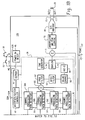
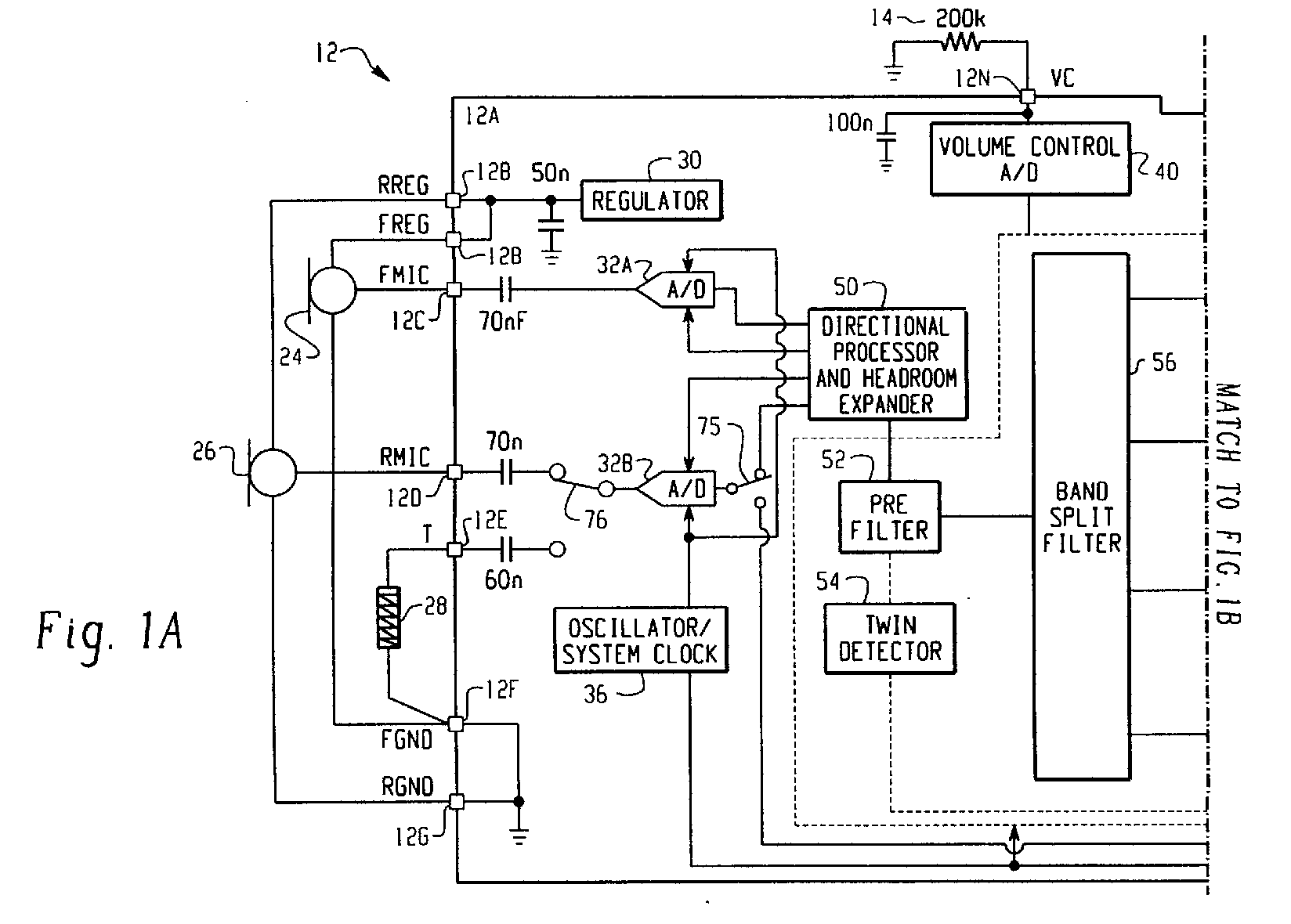
- FIG. 1 is a block diagram of an exemplary digital hearing aid system 12.
- the digital hearing aid system 12 includes several external components 14, 16, 18, 20, 22, 24, 26, 28, and, preferably, a single integrated circuit (IC) 12A.
- the external components include a pair of microphones 24, 26, a tele-coil 28, a volume control potentiometer 24, a memory-select toggle switch 16, battery terminals 18, 22, and a speaker 20.
- Sound is received by the pair of microphones 24, 26, and converted into electrical signals that are coupled to the FMIC 12C and RMIC 12D inputs to the IC 12A.
- FMIC refers to "front microphone”
- RMIC refers to "rear microphone.”
- the microphones 24, 26 are biased between a regulated voltage output from the RREG and FREG pins 12B, and the ground nodes FGND 12F and RGND 12G.
- the regulated voltage output on FREG and RREG is generated internally to the IC 12A by regulator 30.
- the tele-coil 28 is a device used in a hearing aid that magnetically couples to a telephone handset and produces an input current that is proportional to the telephone signal. This input current from the tele-coil 28 is coupled into the rear microphone A/D converter 32B on the IC 12A when the switch 76 is connected to the "T" input pin 12E, indicating that the user of the hearing aid is talking on a telephone.
- the tele-coil 28 is used to prevent acoustic feedback into the system when talking on the telephone.
- the volume control potentiometer 14 is coupled to the volume control input 12N of the IC. This variable resistor is used to set the volume sensitivity of the digital hearing aid.
- the memory-select toggle switch 16 is coupled between the positive voltage supply VB 18 and the memory-select input pin 12L. This switch 16 is used to toggle the digital hearing aid system 12 between a series of setup configurations.
- the device may have been previously programmed for a variety of environmental settings, such as quiet listening, listening to music, a noisy setting, etc. For each of these settings, the system parameters of the IC 12A may have been optimally configured for the particular user. By repeatedly pressing the toggle switch 16, the user may then toggle through the various configurations stored in the read-only memory 44 of the IC 12A.
- the battery terminals 12K, 12H of the IC 12A are preferably coupled to a single 1.3 volt zinc-air battery. This battery provides the primary power source for the digital hearing aid system.
- the last external component is the speaker 20.
- This element is coupled to the differential outputs at pins 12J, 12I of the IC 12A, and converts the processed digital input signals from the two microphones 24, 26 into an audible signal for the user of the digital hearing aid system 12.
- a pair of A/D converters 32A, 32B are coupled between the front and rear microphones 24, 26, and the directional processor and headroom expander 50, and convert the analog input signals into the digital domain for digital processing.
- a single D/A converter 48 converts the processed digital signals back into the analog domain for output by the speaker 20.
- Other system elements include a regulator 30, a volume control A/D 40, an interface/system controller 42, an EEPROM memory 44, a power-on reset circuit 46, a oscillator/system clock 36, a summer 71, and an interpolator and peak clipping circuit 70.
- the sound processor 38 preferably includes a pre-filter 52, a wide-band twin detector 54, a band-split filter 56, a plurality of narrow-band channel processing and twin detectors 58A-58D, a summation block 60, a post filter 62, a notch filter 64, a volume control circuit 66, an automatic gain control output circuit 68, a squelch circuit 72, and a tone generator 74.
- the digital hearing aid system 12 processes digital sound as follows.
- Analog audio signals picked up by the front and rear microphones 24, 26 are coupled to the front and rear A/D converters 32A, 32B, which are preferably Sigma-Delta modulators followed by decimation filters that convert the analog audio inputs from the two microphones into equivalent digital audio signals.
- the rear A/D converter 32B is coupled to the tele-coil input "T" 12E via switch 76.
- Both the front and rear A/D converters 32A, 32B are clocked with the output clock signal from the oscillator/system clock 36 (discussed in more detail below). This same output clock signal is also coupled to the sound processor 38 and the D/A converter 48.
- the front and rear digital sound signals from the two A/D converters 32A, 32B are coupled to the directional processor and headroom expander 50.
- the rear A/D converter 32B is coupled to the processor 50 through switch 75. In a first position, the switch 75 couples the digital output of the rear A/D converter 32 B to the processor 50, and in a second position, the switch 75 couples the digital output of the rear A/D converter 32B to summation block 71 for the purpose of compensating for occlusion.
- Occlusion is the amplification of the users own voice within the ear canal.
- the rear microphone can be moved inside the ear canal to receive this unwanted signal created by the occlusion effect.
- the occlusion effect is usually reduced by putting a mechanical vent in the hearing aid. This vent, however, can cause an oscillation problem as the speaker signal feeds back to the microphone(s) through the vent aperture.
- Another problem associated with traditional venting is a reduced low frequency response (leading to reduced sound quality).
- Yet another limitation occurs when the direct coupling of ambient sounds results in poor directional performance, particularly in the low frequencies.
- the system shown in FIG. 1 solves these problems by canceling the unwanted signal received by the rear microphone 26 by feeding back the rear signal from the A/D converter 32B to summation circuit 71.
- the summation circuit 71 then subtracts the unwanted signal from the processed composite signal to thereby compensate for the occlusion effect.
- the directional processor and headroom expander 50 includes a combination of filtering and delay elements that, when applied to the two digital input signals, form a single, directionally-sensitive response. This directionally-sensitive response is generated such that the gain of the directional processor 50 will be a maximum value for sounds coming from the front microphone 24 and will be a minimum value for sounds coming from the rear microphone 26.
- the headroom expander portion of the processor 50 significantly extends the dynamic range of the A/D conversion, which is very important for high fidelity audio signal processing. It does this by dynamically adjusting the operating points of the A/D converters 32A/32B.
- the headroom expander 50 adjusts the gain before and after the A/D conversion so that the total gain remains unchanged, but the intrinsic dynamic range of the A/D converter block 32A/32B is optimized to the level of the signal being processed.
- the output from the directional processor and headroom expander 50 is coupled to the pre-filter 52 in the sound processor 38, which is a general-purpose filter for pre-conditioning the sound signal prior to any further signal processing steps.
- This "pre-conditioning" can take many forms, and, in combination with corresponding "post-conditioning" in the post filter 62, can be used to generate special effects that may be suited to only a particular class of users.
- the pre-filter 52 could be configured to mimic the transfer function of the user's middle ear, effectively putting the sound signal into the "cochlear domain.”
- Signal processing algorithms to correct a hearing impairment based on, for example, inner hair cell loss and outer hair cell loss, could be applied by the sound processor 38.
- the post-filter 62 could be configured with the inverse response of the pre-filter 52 in order to convert the sound signal back into the "acoustic domain" from the "cochlear domain.”
- the post-filter 62 could be configured with the inverse response of the pre-filter 52 in order to convert the sound signal back into the "acoustic domain" from the "cochlear domain.”
- other pre-conditioning/post-conditioning configurations and corresponding signal processing algorithms could be utilized.
- the pre-conditioned digital sound signal is then coupled to the band-split filter 56, which preferably includes a bank of filters with variable corner frequencies and pass-band gains. These filters are used to split the single input signal into four distinct frequency bands.
- the four output signals from the band-split filter 56 are preferably in-phase so that when they are summed together in summation block 60, after channel processing, nulls or peaks in the composite signal (from the summation block) are minimized.
- Channel processing of the four distinct frequency bands from the band-split filter 56 is accomplished by a plurality of channel processing/twin detector blocks 58A-58D. Although four blocks are shown in FIG. 1, it should be clear that more than four (or less than four) frequency bands could be generated in the band-split filter 56, and thus more or less than four channel processing/twin detector blocks 58 may be utilized with the system.
- Each of the channel processing/twin detectors 58A-58D provide an automatic gain control (“AGC”) function that provides compression and gain on the particular frequency band (channel) being processed. Compression of the channel signals permits quieter sounds to be amplified at a higher gain than louder sounds, for which the gain is compressed. In this manner, the user of the system can hear the full range of sounds since the circuits 58A-58D compress the full range of normal hearing into the reduced dynamic range of the individual user as a function of the individual user's hearing loss within the particular frequency band of the channel.
- AGC automatic gain control
- the channel processing blocks 58A-58D can be configured to employ a twin detector average detection scheme while compressing the input signals.
- This twin detection scheme includes both slow and fast attack/release tracking modules that allow for fast response to transients (in the fast tracking module), while preventing annoying pumping of the input signal (in the slow tracking module) that only a fast time constant would produce.
- the outputs of the fast and slow tracking modules are compared, and the compression parameters are then adjusted accordingly.
- the compression ratio, channel gain, lower and upper thresholds (return to linear point), and the fast and slow time constants (of the fast and slow tracking modules) can be independently programmed and saved in memory 44 for each of the plurality of channel processing blocks 58A-58D.
- FIG. 1 also shows a communication bus 59, which may include one or more connections for coupling the plurality of channel processing blocks 58A-58D.
- This inter-channel communication bus 59 can be used to communicate information between the plurality of channel processing blocks 58A-58D such that each channel (frequency band) can take into account the "energy” level (or some other measure) from the other channel processing blocks.
- each channel processing block 58A-58D would take into account the "energy” level from the higher frequency channels.
- the "energy" level from the wide-band detector 54 may be used by each of the relatively narrow-band channel processing blocks 58A-58D when processing their individual input signals.
- the four channel signals are summed by summation bock 60 to form a composite signal.
- This composite signal is then coupled to the post-filter 62, which may apply a post-processing filter function as discussed above.
- the composite signal is then applied to a notch-filter 64, that attenuates a narrow band of frequencies that is adjustable in the frequency range where hearing aids tend to oscillate.
- This notch filter 64 is used to reduce feedback and prevent unwanted "whistling" of the device.
- the notch filter 64 may include a dynamic transfer function that changes the depth of the notch based upon the magnitude of the input signal.
- the composite signal is coupled to a volume control circuit 66.
- the volume control circuit 66 receives a digital value from the volume control A/D 40, which indicates the desired volume level set by the user via potentiometer 14, and uses this stored digital value to set the gain of an included amplifier circuit.
- the composite signal is coupled to the AGC-output block 68.
- the AGC-output circuit 68 is a high compression ratio, low distortion limiter that is used to prevent pathological signals from causing large scale distorted output signals from the speaker 20 that could be painful and annoying to the user of the device.
- the composite signal is coupled from the AGC-output circuit 68 to a squelch circuit 72, that performs an expansion on low-level signals below an adjustable threshold.
- the squelch circuit 72 uses an output signal from the wide-band detector 54 for this purpose. The expansion of the low-level signals attenuates noise from the microphones and other circuits when the input S/N ratio is small, thus producing a lower noise signal during quiet situations.
- a tone generator block 74 is also shown coupled to the squelch circuit 72, which is included for calibration and testing of the system.
- the output of the squelch circuit 72 is coupled to one input of summation block 71.
- the other input to the summation bock 71 is from the output of the rear A/D converter 32B, when the switch 75 is in the second position:
- These two signals are summed in summation block 71, and passed along to the interpolator and peak clipping circuit 70.
- This circuit 70 also operates on pathological signals, but it operates almost instantaneously to large peak signals and is high distortion limiting.
- the interpolator shifts the signal up in frequency as part of the D/A process and then the signal is clipped so that the distortion products do not alias back into the baseband frequency range.
- the output of the interpolator and peak clipping circuit 70 is coupled from the sound processor 38 to the D/A H-Bridge 48.
- This circuit 48 converts the digital representation of the input sound signals to a pulse density modulated representation with complimentary outputs. These outputs are coupled off-chip through outputs 12J, 12I to the speaker 20, which low-pass filters the outputs and produces an acoustic analog of the output signals.
- the D/A H-Bridge 48 includes an interpolator, a digital Delta-Sigma modulator, and an H-Bridge output stage.
- the D/A H-Bridge 48 is also coupled to and receives the clock signal from the oscillator/system clock 36 (described below).
- the interface/system controller 42 is coupled between a serial data interface pin 12M on the IC 12, and the sound processor 38. This interface is used to communicate with an external controller for the purpose of setting the parameters of the system. These parameters can be stored on-chip in the EEPROM 44. If a "black-out” or “brown-out” condition occurs, then the power-on reset circuit 46 can be used to signal the interface/system controller 42 to configure the system into a known state. Such a condition can occur, for example, if the battery fails.
- the system be able to estimate (or calculate) the root-mean-square (RMS) value of the input audio signal.
- RMS root-mean-square
- This RMS calculation may be performed in the wideband twin detector 54, the narrowband twin detectors 58A-58D, and the AGC-O block 68. Calculating the RMS value of a spectrally complex signal is problematic, however, because of the processing power required to compute the square root component of the RMS calculation.
- the present invention overcomes this problem by estimating the RMS calculation using a quasi-RMS detector.
- the quasi-RMS detector may be implemented in blocks 54, 58A-58D and 68, and comprises a hybrid of an average detector with a peak detector to thereby avoid making the square root calculation.
- An average detector can be implemented using rectification of an AC signal followed by low-pass filtering.
- the rectifier converts the AC signal into a DC component and an AC component.
- Low-pass filtering smoothes the rectified waveform by attenuating the AC component and leaving the DC component intact.
- the magnitude of the DC component is proportional to the amplitude of the original signal, and is therefore useful for metering applications.
- the low-pass filter can be thought of as a "leaky integrator.”
- the average detector also responds gradually to changes in the magnitude of the original signal, meaning that the DC component actually waxes and wanes with a time constant inversely proportional to the frequency of the filter's pole. If the original signal is periodic and of constant amplitude, the output of the low-pass filter is directly proportional to the arithmetic mean of one complete cycle of the rectified waveform.
- a peak detector can be implemented by augmenting the average detector described above as follows. If the amplitude of the rectified signal exceeds that at the output of the low-pass filter, the rectified signal is passed directly to the peak detector's output. If the amplitude of the rectified signal is less than that at the output of the low-pass filter, then the low-pass filter output is passed directly to the peak detector's output. The effect of this modification is to force the detector output to respond instantaneously to sudden increases in amplitude of the incoming signal, and to decay with the inherent time constant of the low-pass filter whenever the amplitude of the incoming signal suddenly drops.
- a peak detector In terms of speech-like audio signals, a peak detector will over-estimate the RMS content, and once again, in applications where signal-processing decision thresholds are meant to correspond to the ranges of human hearing, these thresholds will be in error. Thus, neither an average detector nor a peak detector, alone, can accurately estimate the true RMS content of a signal.
- a quasi-RMS detection algorithm falls somewhere between average detection and peak detection.
- a quasi-RMS detector can be implemented by augmenting the peak detector described above as follows. If the amplitude of the rectified signal exceeds the detector's present output level, then the low-pass filter's time constant is reduced. If the amplitude of the rectified signal is less than the detector's present output level, then the low-pass filter's time constant is increased. As the detector responds to a fluctuating input signal, its low-pass filter time constant adaptively switches between two preset values. The effect of this modification is to force the detector output to respond quickly, but not instantaneously, to sudden increases in amplitude of the incoming signal using the smaller of the two filter time constants. This is defined as the detector's attack time constant. Sudden decreases in signal amplitude invoke the slower filter time constant, which now governs the detector's response time. This is defined as the detector's release time.
- FIG. 2 is a flowchart 100 depicting an exemplary method for estimating the RMS energy of a spectrally complex signal using the quasi-RMS detector described above. This is a software implementation of the quasi-RMS detector. It should be understood, however, that these software method steps could also be implemented in a hardware circuit.
- the method begins at step 102.
- step 104 the next sample in the spectrally complex signal to be measured is obtained.
- the sample is then rectified (by taking the absolute value of the sample) at step 106.
- the rectified sample is then subtracted from a running, present estimate of the signal energy to obtain a difference value "DIFF" at step 108.
- step 110 the method determines whether the DIFF function is greater than zero. If it is not, then the DIFF value is multiplied by a release time constant K1 at step 112. If the DIFF function is greater than zero, then the DIFF value is multiplied by an attack time constant K2 at step 116.
- step 112 or 116 The result of the multiplication from step 112 or 116 is summed with the previous, running estimate of the signal energy at step 118 to generate an estimated RMS value. Steps 112, 116 and 118 thus result in a low-pass filter with an adaptively switching time constant. After filtering, control passes back to step 104 to obtain the next sample of the complex signal.
- the release time constant K1 is equal to 1/(sampling frequency * programmable time constant).
- the sampling frequency could be, for example, 32 KHz, and the programmable time constant could be 4 mSec, giving a K1 value of 1/128.
- multiplying by this 1/128 K value can be easily implemented in a binary shift register by shifting right by 7 register positions, which is a very efficient operation.
- the attack time constant K2 is equal to 1/4 times the release time constant K1, which implements an RMS energy level detector. If K2 were equal to 1, then the low-pass filter would be operating as a peak detector, and if K2 were equal to K1, then the filter would be operating as an average detector. In the digital domain, the multiplication function in step 116 is then easily implemented by shifting right by 5 bit positions in a shift register operation. Thus, using the quasi-RMS algorithm described above, an estimate of the RMS content of a complex signal can be obtained without any complex square root, division, or even multiplication functions.
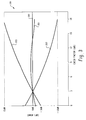
- FIG. 3 is a graph 199 illustrating the performance of an exemplary quasi-RMS detector 201 compared to a typical average detector 202 and a typical peak detector 203.
- the x-axis of the graph 199 represents a range of crest factors (peak to RMS ratios). For example, a square wave may have a 0dB crest factor, a speech signal may have a 12 dB crest factor, and a highly peaky signal may have an 18 dB crest factor.
- the y-axis of the graph 199 represents the error (in dB) exhibited by the exemplary RMS detectors 201, 202, 203 over the range of crest factors. Also illustrated is a performance curve for an ideal RMS meter 200 which exhibits a 0 dB error over the range of crest factors.
- the range of crest factors over which an RMS detector 201, 202, 203 can estimate an RMS value for a complex waveform that is close to the true RMS value (0 dB error) is a good indication of performance.
- the exemplary quasi-RMS detector 201 may estimate RMS values that remain within 1dB of true RMS over the entire range of low crest factor signals.
- the average detector 202 may vary from true RMS by 12 dB, and the peak detector 203 may vary by 15 dB. It should be understood, however, that the error values shown in FIG. 3 are provided for illustrative purposes only, and are not intended as a limitation on the performance of the quasi-RMS detector.
Abstract
Description
Claims (4)
- A method of approximating a root-mean-square (RMS) value for an audio signal in a digital hearing aid, comprising the steps of:receiving the audio signal;rectifying the audio signal to generate a rectified signal;determining a difference between the rectified signal and an estimated present energy value of the audio signal;if the difference is not greater than zero, then multiplying the rectified signal by a release time constant to generate a first filtered signal and summing the first filtered signal with the estimated present energy value to determine the approximate RMS value; andif the difference is greater than zero, then multiplying the rectified signal by an attack time constant to generate a second filtered signal and summing the second filtered signal with the estimated present energy value to determine the approximate RMS value; wherein the attack time constant is less than the release time constant.
- The method of claim 1, wherein the attack time constant is a fraction of the release time constant.
- The method of claim 1, comprising the additional step of:setting the estimated present energy value to the approximate RMS value.
- The method of claim 1, comprising the additional step of:prior to the rectifying step, sampling the audio signal to generate a sampled audio signal, wherein the sampled audio signal is rectified to generate the rectified signal.
Applications Claiming Priority (2)
| Application Number | Priority Date | Filing Date | Title |
|---|---|---|---|
| US28446001P | 2001-04-18 | 2001-04-18 | |
| US284460P | 2001-04-18 |
Publications (3)
| Publication Number | Publication Date |
|---|---|
| EP1251355A2 true EP1251355A2 (en) | 2002-10-23 |
| EP1251355A3 EP1251355A3 (en) | 2003-08-13 |
| EP1251355B1 EP1251355B1 (en) | 2007-12-05 |
Family
ID=23090305
Family Applications (1)
| Application Number | Title | Priority Date | Filing Date |
|---|---|---|---|
| EP02008767A Expired - Lifetime EP1251355B1 (en) | 2001-04-18 | 2002-04-18 | Digital quasi-rms detector |
Country Status (5)
| Country | Link |
|---|---|
| US (1) | US7076073B2 (en) |
| EP (1) | EP1251355B1 (en) |
| AT (1) | ATE380347T1 (en) |
| CA (1) | CA2382358C (en) |
| DE (1) | DE60223869D1 (en) |
Cited By (2)
| Publication number | Priority date | Publication date | Assignee | Title |
|---|---|---|---|---|
| WO2008087089A1 (en) * | 2007-01-16 | 2008-07-24 | Phonic Ear Inc | Sound amplification system |
| US9123329B2 (en) | 2010-06-10 | 2015-09-01 | Huawei Technologies Co., Ltd. | Method and apparatus for generating sideband residual signal |
Families Citing this family (9)
| Publication number | Priority date | Publication date | Assignee | Title |
|---|---|---|---|---|
| US7928876B2 (en) * | 2004-04-09 | 2011-04-19 | Audioasics A/S | Sigma delta modulator |
| US7706473B2 (en) * | 2006-03-24 | 2010-04-27 | Freescale Semiconductor, Inc. | Comparative signal strength detection |
| US8559198B2 (en) * | 2011-06-08 | 2013-10-15 | The Boeing Company | High yield AC-AC power converter and method therefor |
| CN102610232B (en) * | 2012-01-10 | 2013-06-19 | 天津大学 | Method for adjusting self-adaptive audio sensing loudness |
| US9476920B2 (en) * | 2013-12-02 | 2016-10-25 | Smart Energy Instruments Inc. | Methods and devices for determining root mean square of a delta-sigma modulated signal |
| US9699572B2 (en) * | 2015-05-27 | 2017-07-04 | Starkey Laboratories, Inc. | Method and apparatus for suppressing transient sounds in hearing assistance devices |
| US9693153B2 (en) * | 2015-05-27 | 2017-06-27 | Starkey Laboratories, Inc. | Method and apparatus for suppressing transient sounds in hearing assistance devices |
| CA3044079C (en) | 2016-12-13 | 2023-07-11 | QSIC Pty Ltd | Sound management method and system |
| US11641183B2 (en) * | 2018-10-25 | 2023-05-02 | Ear Physics, Llc | Audio dynamics processing control system with integration release window |
Citations (4)
| Publication number | Priority date | Publication date | Assignee | Title |
|---|---|---|---|---|
| US4113997A (en) * | 1977-07-12 | 1978-09-12 | Communications Satellite, Corporation | Analog to digital signal of logarithmic format converter and analog to pseudo-rms value converter and echo canceller utilizing same |
| US5027060A (en) * | 1989-07-31 | 1991-06-25 | Merlin Gerin | Measuring device of the rms value of a signal, notably for current measurement in a solid-state trip device |
| US5027410A (en) * | 1988-11-10 | 1991-06-25 | Wisconsin Alumni Research Foundation | Adaptive, programmable signal processing and filtering for hearing aids |
| US5450268A (en) * | 1993-08-11 | 1995-09-12 | Square D Company | Method and apparatus for RMS current approximation |
Family Cites Families (89)
| Publication number | Priority date | Publication date | Assignee | Title |
|---|---|---|---|---|
| GB1592168A (en) | 1976-11-29 | 1981-07-01 | Oticon Electronics As | Hearing aids |
| DE2658301C2 (en) | 1976-12-22 | 1978-12-07 | Siemens Ag, 1000 Berlin Und 8000 Muenchen | Hearing aid |
| DE2716336B1 (en) | 1977-04-13 | 1978-07-06 | Siemens Ag | Procedure and hearing aid for the compensation of hearing defects |
| DE2908999C2 (en) | 1979-03-08 | 1982-06-09 | Siemens AG, 1000 Berlin und 8000 München | Method for generating acoustic speech signals which are understandable for the extremely hard of hearing and device for carrying out this method |
| US4403118A (en) | 1980-04-25 | 1983-09-06 | Siemens Aktiengesellschaft | Method for generating acoustical speech signals which can be understood by persons extremely hard of hearing and a device for the implementation of said method |
| DE3131193A1 (en) | 1981-08-06 | 1983-02-24 | Siemens AG, 1000 Berlin und 8000 München | DEVICE FOR COMPENSATING HEALTH DAMAGE |
| DK546581A (en) | 1981-12-10 | 1983-06-11 | Danavox As | PROCEDURE FOR ADAPTING THE TRANSFER FUNCTION IN A HEARING DEVICE FOR VARIOUS HEARING DEFECTS AND HEARING DEVICE FOR EXERCISING THE PROCEDURE |
| DE3205686A1 (en) | 1982-02-17 | 1983-08-25 | Robert Bosch Gmbh, 7000 Stuttgart | HOERGERAET |
| DE3205685A1 (en) | 1982-02-17 | 1983-08-25 | Robert Bosch Gmbh, 7000 Stuttgart | HOERGERAET |
| US4689818A (en) | 1983-04-28 | 1987-08-25 | Siemens Hearing Instruments, Inc. | Resonant peak control |
| US4592087B1 (en) | 1983-12-08 | 1996-08-13 | Knowles Electronics Inc | Class D hearing aid amplifier |
| US4653216A (en) * | 1984-04-13 | 1987-03-31 | Daiwa Seiko Inc. | Tube for fishing rod |
| US4696032A (en) | 1985-02-26 | 1987-09-22 | Siemens Corporate Research & Support, Inc. | Voice switched gain system |
| DE3672082D1 (en) | 1985-10-16 | 1990-07-19 | Siemens Ag | HOERGERAET. |
| DE8529437U1 (en) | 1985-10-16 | 1987-06-11 | Siemens Ag, 1000 Berlin Und 8000 Muenchen, De | |
| US5029217A (en) | 1986-01-21 | 1991-07-02 | Harold Antin | Digital hearing enhancement apparatus |
| US4947432B1 (en) | 1986-02-03 | 1993-03-09 | Programmable hearing aid | |
| US4750207A (en) | 1986-03-31 | 1988-06-07 | Siemens Hearing Instruments, Inc. | Hearing aid noise suppression system |
| DE3734946A1 (en) | 1987-10-15 | 1989-05-03 | Siemens Ag | HEARING DEVICE WITH POSSIBILITY TO TELEPHONE |
| US4887299A (en) | 1987-11-12 | 1989-12-12 | Nicolet Instrument Corporation | Adaptive, programmable signal processing hearing aid |
| DE3802903A1 (en) | 1988-02-01 | 1989-08-10 | Siemens Ag | LANGUAGE TRANSFER DEVICE |
| US4852175A (en) | 1988-02-03 | 1989-07-25 | Siemens Hearing Instr Inc | Hearing aid signal-processing system |
| US4882762A (en) | 1988-02-23 | 1989-11-21 | Resound Corporation | Multi-band programmable compression system |
| US5111419A (en) | 1988-03-23 | 1992-05-05 | Central Institute For The Deaf | Electronic filters, signal conversion apparatus, hearing aids and methods |
| US4989251A (en) | 1988-05-10 | 1991-01-29 | Diaphon Development Ab | Hearing aid programming interface and method |
| US4868880A (en) | 1988-06-01 | 1989-09-19 | Yale University | Method and device for compensating for partial hearing loss |
| DE3834962A1 (en) | 1988-10-13 | 1990-04-19 | Siemens Ag | DIGITAL PROGRAMMING DEVICE FOR HOUR DEVICES |
| DE3900588A1 (en) | 1989-01-11 | 1990-07-19 | Toepholm & Westermann | REMOTE CONTROLLED, PROGRAMMABLE HOUR DEVICE SYSTEM |
| JPH02192300A (en) | 1989-01-19 | 1990-07-30 | Citizen Watch Co Ltd | Digital gain control circuit for hearing aid |
| US4947433A (en) | 1989-03-29 | 1990-08-07 | Siemens Hearing Instruments, Inc. | Circuit for use in programmable hearing aids |
| DK164349C (en) | 1989-08-22 | 1992-11-02 | Oticon As | HEARING DEVICE WITH BACKUP COMPENSATION |
| NO169689C (en) | 1989-11-30 | 1992-07-22 | Nha As | PROGRAMMABLE HYBRID HEARING DEVICE WITH DIGITAL SIGNAL TREATMENT AND PROCEDURE FOR DETECTION AND SIGNAL TREATMENT AT THE SAME. |
| ATE118928T1 (en) | 1990-07-25 | 1995-03-15 | Siemens Audiologische Technik | HEARING AID CIRCUIT WITH AN POWER STAMP WITH A LIMITING DEVICE. |
| DE59008091D1 (en) | 1990-10-12 | 1995-02-02 | Siemens Ag | Hearing aid with a data storage device. |
| EP0495328B1 (en) | 1991-01-15 | 1996-07-17 | International Business Machines Corporation | Sigma delta converter |
| US5278912A (en) | 1991-06-28 | 1994-01-11 | Resound Corporation | Multiband programmable compression system |
| US5389829A (en) | 1991-09-27 | 1995-02-14 | Exar Corporation | Output limiter for class-D BICMOS hearing aid output amplifier |
| US5247581A (en) | 1991-09-27 | 1993-09-21 | Exar Corporation | Class-d bicmos hearing aid output amplifier |
| US5189006A (en) * | 1991-11-06 | 1993-02-23 | Philip Morris Incorporated | Palladium-tin catalysts for acyloxylation of alkylaromatic compounds |
| US5347587A (en) | 1991-11-20 | 1994-09-13 | Sharp Kabushiki Kaisha | Speaker driving device |
| EP0557847B1 (en) | 1992-02-27 | 1995-12-27 | Siemens Audiologische Technik GmbH | Head-mounted hearing aid |
| US5241310A (en) | 1992-03-02 | 1993-08-31 | General Electric Company | Wide dynamic range delta sigma analog-to-digital converter with precise gain tracking |
| US5448644A (en) | 1992-06-29 | 1995-09-05 | Siemens Audiologische Technik Gmbh | Hearing aid |
| DE59204944D1 (en) | 1992-06-29 | 1996-02-15 | Siemens Audiologische Technik | Hearing aid |
| EP0597523B1 (en) | 1992-11-09 | 1997-07-23 | Koninklijke Philips Electronics N.V. | Digital-to-analog converter |
| DE4321788C1 (en) | 1993-06-30 | 1994-08-18 | Siemens Audiologische Technik | Interface for serial data transmission between a hearing aid and a control device |
| US5376892A (en) | 1993-07-26 | 1994-12-27 | Texas Instruments Incorporated | Sigma delta saturation detector and soft resetting circuit |
| US5608803A (en) | 1993-08-05 | 1997-03-04 | The University Of New Mexico | Programmable digital hearing aid |
| US5412734A (en) | 1993-09-13 | 1995-05-02 | Thomasson; Samuel L. | Apparatus and method for reducing acoustic feedback |
| US5651071A (en) | 1993-09-17 | 1997-07-22 | Audiologic, Inc. | Noise reduction system for binaural hearing aid |
| US5479522A (en) | 1993-09-17 | 1995-12-26 | Audiologic, Inc. | Binaural hearing aid |
| EP0585976A3 (en) | 1993-11-10 | 1994-06-01 | Phonak Ag | Hearing aid with cancellation of acoustic feedback |
| DE4340817A1 (en) | 1993-12-01 | 1995-06-08 | Toepholm & Westermann | Circuit arrangement for the automatic control of hearing aids |
| US5561814A (en) * | 1993-12-22 | 1996-10-01 | Intel Corporation | Methods and apparatus for determining memory operating characteristics for given memory locations via assigned address ranges |
| EP0674463A1 (en) | 1994-03-23 | 1995-09-27 | Siemens Audiologische Technik GmbH | Programmable hearing aid |
| EP0674464A1 (en) | 1994-03-23 | 1995-09-27 | Siemens Audiologische Technik GmbH | Programmable hearing aid with fuzzy logic controller |
| EP0676909A1 (en) | 1994-03-31 | 1995-10-11 | Siemens Audiologische Technik GmbH | Programmable hearing aid |
| DK0681411T3 (en) | 1994-05-06 | 2003-05-19 | Siemens Audiologische Technik | Programmable hearing aid |
| US5500902A (en) | 1994-07-08 | 1996-03-19 | Stockham, Jr.; Thomas G. | Hearing aid device incorporating signal processing techniques |
| EP0712261A1 (en) | 1994-11-10 | 1996-05-15 | Siemens Audiologische Technik GmbH | Programmable hearing aid |
| DE4441996A1 (en) | 1994-11-26 | 1996-05-30 | Toepholm & Westermann | Hearing aid |
| JPH08265468A (en) | 1995-03-20 | 1996-10-11 | Brother Ind Ltd | Facsimile equipment |
| US5862238A (en) | 1995-09-11 | 1999-01-19 | Starkey Laboratories, Inc. | Hearing aid having input and output gain compression circuits |
| AU7118696A (en) | 1995-10-10 | 1997-04-30 | Audiologic, Inc. | Digital signal processing hearing aid with processing strategy selection |
| US5719524A (en) * | 1995-10-11 | 1998-02-17 | Telcom Semiconductor, Inc. | Circuit having an input terminal for controlling two functions |
| DE19545760C1 (en) * | 1995-12-07 | 1997-02-20 | Siemens Audiologische Technik | Digital hearing aid |
| DE19611026C2 (en) | 1996-03-20 | 2001-09-20 | Siemens Audiologische Technik | Distortion suppression in hearing aids with AGC |
| EP0798947A1 (en) | 1996-03-27 | 1997-10-01 | Siemens Audiologische Technik GmbH | Method and circuit for data processing, in particular for signal data in a digital progammable hearing aid |
| US5719528A (en) | 1996-04-23 | 1998-02-17 | Phonak Ag | Hearing aid device |
| US6108431A (en) | 1996-05-01 | 2000-08-22 | Phonak Ag | Loudness limiter |
| DE29608215U1 (en) | 1996-05-06 | 1996-08-01 | Siemens Audiologische Technik | Electric hearing aid |
| US5815102A (en) | 1996-06-12 | 1998-09-29 | Audiologic, Incorporated | Delta sigma pwm dac to reduce switching |
| EP0814635B1 (en) | 1996-06-21 | 2002-10-02 | Siemens Audiologische Technik GmbH | Hearing aid |
| EP0814636A1 (en) | 1996-06-21 | 1997-12-29 | Siemens Audiologische Technik GmbH | Hearing aid |
| US5896101A (en) | 1996-09-16 | 1999-04-20 | Audiologic Hearing Systems, L.P. | Wide dynamic range delta sigma A/D converter |
| EP0845921A1 (en) | 1996-10-23 | 1998-06-03 | Siemens Audiologische Technik GmbH | Method and circuit for regulating the volume in digital hearing aids |
| JP2904272B2 (en) | 1996-12-10 | 1999-06-14 | 日本電気株式会社 | Digital hearing aid and hearing aid processing method thereof |
| US6044162A (en) | 1996-12-20 | 2000-03-28 | Sonic Innovations, Inc. | Digital hearing aid using differential signal representations |
| DE19703228B4 (en) | 1997-01-29 | 2006-08-03 | Siemens Audiologische Technik Gmbh | Method for amplifying input signals of a hearing aid and circuit for carrying out the method |
| US5836801A (en) * | 1997-03-12 | 1998-11-17 | Lin; Kuo Jung | Climbing toy device |
| US6240192B1 (en) | 1997-04-16 | 2001-05-29 | Dspfactory Ltd. | Apparatus for and method of filtering in an digital hearing aid, including an application specific integrated circuit and a programmable digital signal processor |
| US6236731B1 (en) | 1997-04-16 | 2001-05-22 | Dspfactory Ltd. | Filterbank structure and method for filtering and separating an information signal into different bands, particularly for audio signal in hearing aids |
| DE19720651C2 (en) | 1997-05-16 | 2001-07-12 | Siemens Audiologische Technik | Hearing aid with various assemblies for recording, processing and adapting a sound signal to the hearing ability of a hearing impaired person |
| US6049616A (en) * | 1997-06-17 | 2000-04-11 | Weiner; Keith | Dynamic range restorer and method |
| US6049618A (en) | 1997-06-30 | 2000-04-11 | Siemens Hearing Instruments, Inc. | Hearing aid having input AGC and output AGC |
| DE59813964D1 (en) | 1997-11-12 | 2007-05-24 | Siemens Audiologische Technik | Hearing aid and method for setting audiological / acoustic parameters |
| DE69908662T2 (en) | 1999-08-03 | 2004-05-13 | Widex A/S | HEARING AID WITH ADAPTIVE ADJUSTMENT OF MICROPHONES |
| US6633202B2 (en) * | 2001-04-12 | 2003-10-14 | Gennum Corporation | Precision low jitter oscillator circuit |
| DK1251714T4 (en) | 2001-04-12 | 2015-07-20 | Sound Design Technologies Ltd | Digital hearing aid system |
-
2002
- 2002-04-18 EP EP02008767A patent/EP1251355B1/en not_active Expired - Lifetime
- 2002-04-18 US US10/125,185 patent/US7076073B2/en not_active Expired - Lifetime
- 2002-04-18 AT AT02008767T patent/ATE380347T1/en not_active IP Right Cessation
- 2002-04-18 DE DE60223869T patent/DE60223869D1/en not_active Expired - Lifetime
- 2002-04-18 CA CA002382358A patent/CA2382358C/en not_active Expired - Fee Related
Patent Citations (4)
| Publication number | Priority date | Publication date | Assignee | Title |
|---|---|---|---|---|
| US4113997A (en) * | 1977-07-12 | 1978-09-12 | Communications Satellite, Corporation | Analog to digital signal of logarithmic format converter and analog to pseudo-rms value converter and echo canceller utilizing same |
| US5027410A (en) * | 1988-11-10 | 1991-06-25 | Wisconsin Alumni Research Foundation | Adaptive, programmable signal processing and filtering for hearing aids |
| US5027060A (en) * | 1989-07-31 | 1991-06-25 | Merlin Gerin | Measuring device of the rms value of a signal, notably for current measurement in a solid-state trip device |
| US5450268A (en) * | 1993-08-11 | 1995-09-12 | Square D Company | Method and apparatus for RMS current approximation |
Cited By (2)
| Publication number | Priority date | Publication date | Assignee | Title |
|---|---|---|---|---|
| WO2008087089A1 (en) * | 2007-01-16 | 2008-07-24 | Phonic Ear Inc | Sound amplification system |
| US9123329B2 (en) | 2010-06-10 | 2015-09-01 | Huawei Technologies Co., Ltd. | Method and apparatus for generating sideband residual signal |
Also Published As
| Publication number | Publication date |
|---|---|
| ATE380347T1 (en) | 2007-12-15 |
| US20030012393A1 (en) | 2003-01-16 |
| CA2382358C (en) | 2007-01-09 |
| US7076073B2 (en) | 2006-07-11 |
| EP1251355A3 (en) | 2003-08-13 |
| CA2382358A1 (en) | 2002-10-18 |
| DE60223869D1 (en) | 2008-01-17 |
| EP1251355B1 (en) | 2007-12-05 |
Similar Documents
| Publication | Publication Date | Title |
|---|---|---|
| CA2382362C (en) | Inter-channel communication in a multi-channel digital hearing instrument | |
| US7409068B2 (en) | Low-noise directional microphone system | |
| US7433481B2 (en) | Digital hearing aid system | |
| US7242778B2 (en) | Hearing instrument with self-diagnostics | |
| JP2962732B2 (en) | Hearing aid signal processing system | |
| US8290190B2 (en) | Method for sound processing in a hearing aid and a hearing aid | |
| US20050090295A1 (en) | Communication headset with signal processing capability | |
| US20020076072A1 (en) | Software implemented loudness normalization for a digital hearing aid | |
| WO2000018184A2 (en) | Hearing aids based on models of cochlear compression | |
| US7076073B2 (en) | Digital quasi-RMS detector | |
| US20030223597A1 (en) | Adapative noise compensation for dynamic signal enhancement | |
| EP1251716B1 (en) | In-situ transducer modeling in a digital hearing instrument | |
| CA2381516C (en) | Digital hearing aid system | |
| US20060139030A1 (en) | System and method for diagnosing manufacturing defects in a hearing instrument | |
| CA2582648C (en) | Digital hearing aid system | |
| KR100513714B1 (en) | Apparatus for estimating sound power of each channel in multi-channel hearing aid and method thereof |
Legal Events
| Date | Code | Title | Description |
|---|---|---|---|
| PUAI | Public reference made under article 153(3) epc to a published international application that has entered the european phase |
Free format text: ORIGINAL CODE: 0009012 |
|
| AK | Designated contracting states |
Kind code of ref document: A2 Designated state(s): AT BE CH CY DE DK ES FI FR GB GR IE IT LI LU MC NL PT SE TR |
|
| AX | Request for extension of the european patent |
Free format text: AL;LT;LV;MK;RO;SI |
|
| PUAL | Search report despatched |
Free format text: ORIGINAL CODE: 0009013 |
|
| AK | Designated contracting states |
Designated state(s): AT BE CH CY DE DK ES FI FR GB GR IE IT LI LU MC NL PT SE TR |
|
| AX | Request for extension of the european patent |
Extension state: AL LT LV MK RO SI |
|
| 17P | Request for examination filed |
Effective date: 20040120 |
|
| AKX | Designation fees paid |
Designated state(s): AT BE CH CY DE DK ES FI FR GB GR IE IT LI LU MC NL PT SE TR |
|
| 17Q | First examination report despatched |
Effective date: 20050120 |
|
| GRAP | Despatch of communication of intention to grant a patent |
Free format text: ORIGINAL CODE: EPIDOSNIGR1 |
|
| GRAS | Grant fee paid |
Free format text: ORIGINAL CODE: EPIDOSNIGR3 |
|
| GRAA | (expected) grant |
Free format text: ORIGINAL CODE: 0009210 |
|
| AK | Designated contracting states |
Kind code of ref document: B1 Designated state(s): AT BE CH CY DE DK ES FI FR GB GR IE IT LI LU MC NL PT SE TR |
|
| REG | Reference to a national code |
Ref country code: GB Ref legal event code: FG4D |
|
| REG | Reference to a national code |
Ref country code: IE Ref legal event code: FG4D |
|
| REG | Reference to a national code |
Ref country code: CH Ref legal event code: EP |
|
| REF | Corresponds to: |
Ref document number: 60223869 Country of ref document: DE Date of ref document: 20080117 Kind code of ref document: P |
|
| RAP2 | Party data changed (patent owner data changed or rights of a patent transferred) |
Owner name: SOUND DESIGN TECHNOLOGIES LTD. |
|
| NLT2 | Nl: modifications (of names), taken from the european patent patent bulletin |
Owner name: SOUND DESIGN TECHNOLOGIES LTD. Effective date: 20080123 |
|
| PG25 | Lapsed in a contracting state [announced via postgrant information from national office to epo] |
Ref country code: LI Free format text: LAPSE BECAUSE OF FAILURE TO SUBMIT A TRANSLATION OF THE DESCRIPTION OR TO PAY THE FEE WITHIN THE PRESCRIBED TIME-LIMIT Effective date: 20071205 Ref country code: NL Free format text: LAPSE BECAUSE OF FAILURE TO SUBMIT A TRANSLATION OF THE DESCRIPTION OR TO PAY THE FEE WITHIN THE PRESCRIBED TIME-LIMIT Effective date: 20071205 Ref country code: SE Free format text: LAPSE BECAUSE OF FAILURE TO SUBMIT A TRANSLATION OF THE DESCRIPTION OR TO PAY THE FEE WITHIN THE PRESCRIBED TIME-LIMIT Effective date: 20080305 Ref country code: ES Free format text: LAPSE BECAUSE OF FAILURE TO SUBMIT A TRANSLATION OF THE DESCRIPTION OR TO PAY THE FEE WITHIN THE PRESCRIBED TIME-LIMIT Effective date: 20080316 Ref country code: CH Free format text: LAPSE BECAUSE OF FAILURE TO SUBMIT A TRANSLATION OF THE DESCRIPTION OR TO PAY THE FEE WITHIN THE PRESCRIBED TIME-LIMIT Effective date: 20071205 |
|
| PG25 | Lapsed in a contracting state [announced via postgrant information from national office to epo] |
Ref country code: FI Free format text: LAPSE BECAUSE OF FAILURE TO SUBMIT A TRANSLATION OF THE DESCRIPTION OR TO PAY THE FEE WITHIN THE PRESCRIBED TIME-LIMIT Effective date: 20071205 |
|
| NLV1 | Nl: lapsed or annulled due to failure to fulfill the requirements of art. 29p and 29m of the patents act | ||
| REG | Reference to a national code |
Ref country code: CH Ref legal event code: PL |
|
| PG25 | Lapsed in a contracting state [announced via postgrant information from national office to epo] |
Ref country code: AT Free format text: LAPSE BECAUSE OF FAILURE TO SUBMIT A TRANSLATION OF THE DESCRIPTION OR TO PAY THE FEE WITHIN THE PRESCRIBED TIME-LIMIT Effective date: 20071205 |
|
| PG25 | Lapsed in a contracting state [announced via postgrant information from national office to epo] |
Ref country code: BE Free format text: LAPSE BECAUSE OF FAILURE TO SUBMIT A TRANSLATION OF THE DESCRIPTION OR TO PAY THE FEE WITHIN THE PRESCRIBED TIME-LIMIT Effective date: 20071205 |
|
| PG25 | Lapsed in a contracting state [announced via postgrant information from national office to epo] |
Ref country code: PT Free format text: LAPSE BECAUSE OF FAILURE TO SUBMIT A TRANSLATION OF THE DESCRIPTION OR TO PAY THE FEE WITHIN THE PRESCRIBED TIME-LIMIT Effective date: 20080505 |
|
| EN | Fr: translation not filed | ||
| PLBE | No opposition filed within time limit |
Free format text: ORIGINAL CODE: 0009261 |
|
| STAA | Information on the status of an ep patent application or granted ep patent |
Free format text: STATUS: NO OPPOSITION FILED WITHIN TIME LIMIT |
|
| PG25 | Lapsed in a contracting state [announced via postgrant information from national office to epo] |
Ref country code: DE Free format text: LAPSE BECAUSE OF FAILURE TO SUBMIT A TRANSLATION OF THE DESCRIPTION OR TO PAY THE FEE WITHIN THE PRESCRIBED TIME-LIMIT Effective date: 20080306 Ref country code: DK Free format text: LAPSE BECAUSE OF FAILURE TO SUBMIT A TRANSLATION OF THE DESCRIPTION OR TO PAY THE FEE WITHIN THE PRESCRIBED TIME-LIMIT Effective date: 20071205 |
|
| 26N | No opposition filed |
Effective date: 20080908 |
|
| PG25 | Lapsed in a contracting state [announced via postgrant information from national office to epo] |
Ref country code: MC Free format text: LAPSE BECAUSE OF NON-PAYMENT OF DUE FEES Effective date: 20080430 |
|
| GBPC | Gb: european patent ceased through non-payment of renewal fee |
Effective date: 20080418 |
|
| PG25 | Lapsed in a contracting state [announced via postgrant information from national office to epo] |
Ref country code: GR Free format text: LAPSE BECAUSE OF FAILURE TO SUBMIT A TRANSLATION OF THE DESCRIPTION OR TO PAY THE FEE WITHIN THE PRESCRIBED TIME-LIMIT Effective date: 20080306 |
|
| PG25 | Lapsed in a contracting state [announced via postgrant information from national office to epo] |
Ref country code: FR Free format text: LAPSE BECAUSE OF FAILURE TO SUBMIT A TRANSLATION OF THE DESCRIPTION OR TO PAY THE FEE WITHIN THE PRESCRIBED TIME-LIMIT Effective date: 20081003 Ref country code: IE Free format text: LAPSE BECAUSE OF NON-PAYMENT OF DUE FEES Effective date: 20080418 |
|
| PG25 | Lapsed in a contracting state [announced via postgrant information from national office to epo] |
Ref country code: GB Free format text: LAPSE BECAUSE OF NON-PAYMENT OF DUE FEES Effective date: 20080418 |
|
| PG25 | Lapsed in a contracting state [announced via postgrant information from national office to epo] |
Ref country code: CY Free format text: LAPSE BECAUSE OF FAILURE TO SUBMIT A TRANSLATION OF THE DESCRIPTION OR TO PAY THE FEE WITHIN THE PRESCRIBED TIME-LIMIT Effective date: 20071205 |
|
| PG25 | Lapsed in a contracting state [announced via postgrant information from national office to epo] |
Ref country code: LU Free format text: LAPSE BECAUSE OF NON-PAYMENT OF DUE FEES Effective date: 20080418 |
|
| PG25 | Lapsed in a contracting state [announced via postgrant information from national office to epo] |
Ref country code: TR Free format text: LAPSE BECAUSE OF FAILURE TO SUBMIT A TRANSLATION OF THE DESCRIPTION OR TO PAY THE FEE WITHIN THE PRESCRIBED TIME-LIMIT Effective date: 20071205 |
|
| PG25 | Lapsed in a contracting state [announced via postgrant information from national office to epo] |
Ref country code: IT Free format text: LAPSE BECAUSE OF NON-PAYMENT OF DUE FEES Effective date: 20080430 |