EP1246126A2 - Input device capable of generating different input signals on single operating surface - Google Patents
Input device capable of generating different input signals on single operating surface Download PDFInfo
- Publication number
- EP1246126A2 EP1246126A2 EP02251065A EP02251065A EP1246126A2 EP 1246126 A2 EP1246126 A2 EP 1246126A2 EP 02251065 A EP02251065 A EP 02251065A EP 02251065 A EP02251065 A EP 02251065A EP 1246126 A2 EP1246126 A2 EP 1246126A2
- Authority
- EP
- European Patent Office
- Prior art keywords
- input
- detection members
- detection
- input device
- operated
- Prior art date
- Legal status (The legal status is an assumption and is not a legal conclusion. Google has not performed a legal analysis and makes no representation as to the accuracy of the status listed.)
- Withdrawn
Links
Images


Classifications
-
- G—PHYSICS
- G06—COMPUTING; CALCULATING OR COUNTING
- G06F—ELECTRIC DIGITAL DATA PROCESSING
- G06F3/00—Input arrangements for transferring data to be processed into a form capable of being handled by the computer; Output arrangements for transferring data from processing unit to output unit, e.g. interface arrangements
- G06F3/01—Input arrangements or combined input and output arrangements for interaction between user and computer
- G06F3/02—Input arrangements using manually operated switches, e.g. using keyboards or dials
- G06F3/023—Arrangements for converting discrete items of information into a coded form, e.g. arrangements for interpreting keyboard generated codes as alphanumeric codes, operand codes or instruction codes
- G06F3/0233—Character input methods
-
- G—PHYSICS
- G06—COMPUTING; CALCULATING OR COUNTING
- G06F—ELECTRIC DIGITAL DATA PROCESSING
- G06F3/00—Input arrangements for transferring data to be processed into a form capable of being handled by the computer; Output arrangements for transferring data from processing unit to output unit, e.g. interface arrangements
- G06F3/01—Input arrangements or combined input and output arrangements for interaction between user and computer
- G06F3/03—Arrangements for converting the position or the displacement of a member into a coded form
- G06F3/041—Digitisers, e.g. for touch screens or touch pads, characterised by the transducing means
- G06F3/044—Digitisers, e.g. for touch screens or touch pads, characterised by the transducing means by capacitive means
- G06F3/0446—Digitisers, e.g. for touch screens or touch pads, characterised by the transducing means by capacitive means using a grid-like structure of electrodes in at least two directions, e.g. using row and column electrodes
-
- G—PHYSICS
- G06—COMPUTING; CALCULATING OR COUNTING
- G06F—ELECTRIC DIGITAL DATA PROCESSING
- G06F3/00—Input arrangements for transferring data to be processed into a form capable of being handled by the computer; Output arrangements for transferring data from processing unit to output unit, e.g. interface arrangements
- G06F3/01—Input arrangements or combined input and output arrangements for interaction between user and computer
- G06F3/048—Interaction techniques based on graphical user interfaces [GUI]
- G06F3/0487—Interaction techniques based on graphical user interfaces [GUI] using specific features provided by the input device, e.g. functions controlled by the rotation of a mouse with dual sensing arrangements, or of the nature of the input device, e.g. tap gestures based on pressure sensed by a digitiser
- G06F3/0488—Interaction techniques based on graphical user interfaces [GUI] using specific features provided by the input device, e.g. functions controlled by the rotation of a mouse with dual sensing arrangements, or of the nature of the input device, e.g. tap gestures based on pressure sensed by a digitiser using a touch-screen or digitiser, e.g. input of commands through traced gestures
- G06F3/04883—Interaction techniques based on graphical user interfaces [GUI] using specific features provided by the input device, e.g. functions controlled by the rotation of a mouse with dual sensing arrangements, or of the nature of the input device, e.g. tap gestures based on pressure sensed by a digitiser using a touch-screen or digitiser, e.g. input of commands through traced gestures for inputting data by handwriting, e.g. gesture or text
-
- H—ELECTRICITY
- H04—ELECTRIC COMMUNICATION TECHNIQUE
- H04M—TELEPHONIC COMMUNICATION
- H04M1/00—Substation equipment, e.g. for use by subscribers
- H04M1/02—Constructional features of telephone sets
- H04M1/23—Construction or mounting of dials or of equivalent devices; Means for facilitating the use thereof
Definitions
- the present invention relates to an input device which is controlled by a controller and which can generate different input signals on a single operating surface.
- Input devices such as a keyboard and pointing device, are typically connected to a computer and are used to input data into or to operate the computer. For example, moving a cursor or pointer onto a mark, which is referred to as an icon, displayed on the screen to give an instruction causes the subsequent processing to be initiated.
- This type of pointing device may have an operating surface with flat-type (pad-type) detection members.
- moving a finger on the operating surface causes the generation of movement data, so that a cursor on the screen moves to a desired position in accordance with the direction of the finger movement.
- detection members are used to input numbers or symbols, the input is performed by clicking number keys displayed as images on the screen or by pressing number keys on the keyboard.
- An input device which includes such detection members, however, is designed based on the size of the operating surface. Thus, varying the size thereof requires a change in the design itself, making it impossible to be used as an input device for various types of equipment. Consequently, such an input device has been utilized in limited applications only, for example, in computers.
- the present invention has been made to overcome the conventional problems, and an object thereof is to provide an input device in which the operating surface thereof can be changed to various sizes such that the input device can be mounted on various types of equipment.
- an input device which is controlled by a controller.
- the input device includes a plurality of detection members which are provided on an operating surface and which are switched on and off; and indicators which indicate corresponding input portions of the detection members.
- the controller generates an operation signal in accordance with the switching-on or switching-off.
- the controller allows a single input mode, in which operation of one of the detection members is processed as an operation input with respect to a corresponding one of the input portions, to be set, and allows a motion input mode, in which continuous operation of some of the detection members is processed as a motion operation input in accordance with the positional relationship of the operated detection members, to be set.
- an input device which is controlled by a controller.
- the input device includes a plurality of detection members which are provided on an operating surface and which detect a contact and a movement of a manipulator; and indicators which indicate corresponding input portions of the detection members.
- the controller generates an operation signal in accordance with the operation of at least one of the detection members.
- the controller allows a single input mode, in which a touch of a manipulator on one of the detection members is processed as an operation input with respect to a corresponding one of the input portions, to be set, and allows a motion input mode, in which continuous movement of the manipulator across some of the detection members is processed as a motion operation input in accordance with the positional relationship of the operated detection members, to be set.
- the detection members can be combined into any arrangement to provide the input device with an arbitrary size and shape, so that they can be mounted on equipment with various sizes. Additionally, since the input device allows for two different types of input operations on the single operating surface, it is advantageously used in multifunctional applications, with enhanced operability.
- the single input mode and the motion input mode may be switched by external input using another input means that is provided on the detection member or the operating surface.
- the controller recognizes the input portion of the operated detection member as a reference position and sets a plurality of the detection members that are adjacent to the operated detection member into a detectable state.
- the controller may recognize the input portion of the newly operated detection member as a new reference position and sets a plurality of the detection members that are adjacent to the newly operated detection member into a detectable state.
- the input device is provided with display means, and in the setting of the motion input mode, the display means displays information in accordance with the motion input information resulting from the operation of the detection members.
- the display means is provided on the same housing on which the detection members are provided, or is provided separately from the housing.
- a portable telephone 10 has a casing (housing) 3.
- the casing 3 includes an operating surface on which an input device 1, a display (display means) 2, and switches 6 are arranged.
- switches 6 are arranged on the casing 3, or alternatively, just the input device 1 and the display 2 may be provided thereon.
- the input device 1 includes a combination of a plurality, i.e., a total of 12 detection members 4 arranged vertically and horizontally, such that the overall profile of the input device 1 is square.
- the detection members 4 are arranged adjacent to one another, and the surfaces of the detection members 4 respectively serve as individual input portions.
- the detection members 4 is a capacitance or pressure-sensitive type and has a simple mechanism, and can detect the ON/OFF switching upon the touch of a finger, pen, or the like.
- Each detection member 4 may also be of a type that can detect the movement of a manipulator such as a finger or pen on the surface of the detection member 4 in addition to the capability of detecting the ON/OFF switching.
- an x-direction detecting electrode and a y-direction detecting electrode which are formed of an Ag (silver) based paste, are arranged to oppose each other in a matrix on both sides of a resin sheet formed of PET (polyethylene terephthalate) or the like.
- the resin sheet and the electrodes are arranged on a substrate having a resin sheet on which a conductive pattern is formed so that flexible deformation is provided. This allows inputting of coordinate data upon the touch of a dielectric body such as a finger on the surfaces of the detection members 4.
- the detection members 4 include a resistance element having potentials in x- and y-directions and a conductive element facing the resistance element. Upon the touch of a finger or the like, the conductive element and the resistance element are brought in contact with each other, causing the resistance value to change, which allows inputting of coordinate data.
- Indicators 5 are formed on the respective surfaces of the detection members 4 by printing or the like, with each indicator 5 indicating an input portion for a number, symbol, or the like.
- a sheet, made of a resin such as PET, may be stacked on the surfaces of the detection members 4 so that indicators 5 each indicating the input portion for a number, symbol, or the like are printed on the obverse surface of the sheet.
- the display 2 is display means for displaying various pieces of information, and can display information input from the input device 1 or information received from another portable telephone or the like. For example, as shown in FIG. 2, with a plurality of icons 20 being displayed in the x- and y-directions in a matrix, selecting and executing one of the icons 20 causes the displayed information to be switched to the previous or subsequent screen, or causes a predetermined program to run.
- the portable telephone 10 includes a controller 11 to which the display 2 and the detection members 4 are connected. Also connected to the controller 11 are a memory 12, a transmitter 13, a receiver 14, etc.
- the controller 11 allows switching between different types of modes, that is, a motion input mode and a single input mode, each handling an operation signal different from the other.
- the switching between the motion input mode and the single input mode may be made by operating one of the detection members 4 or by external input using another input means such as the switches 6.
- the switching between the modes may be automatically made by means of software, in accordance with a displayed screen of the display 2.
- the operation is individually processed as an operation input with respect to one of the input portions.
- this mode it is possible to switch between ON and OFF, and when the indicator 5 is pressed or touched with a finger, such an operation is detected and an operation signal corresponding to the input portion of the indicator 5 is generated by the controller 11. For example, in FIG. 1, when the indicator 5 on which number "1" is indicated is pressed, number "1" is displayed on the screen of the display 2, or a command assigned to "1" is then executed.
- the operation is processed as a motion operation input in accordance with the positional relationship of the operated detection members 4.
- moving a finger on the input device 1 causes generation of coordinate data in an X-Y plane in accordance with the moving direction of the finger, regardless of indications provided on the indicators 5.
- the display 2 is in the exemplary state shown in FIG. 2, the coordinate data (motion input information) is converted into a signal for moving the cursor 21, so that the movement of the cursor 21 is displayed on the screen of the display 2.
- Detection means in the motion input mode will now be described with reference to FIGS. 4 and 5.
- the basic operation of the input device 1 illustrated therein is the same as that of the input device 1 described above, except for the slightly different arrangement of the detection members 4.
- the number and/or arrangement of the detection members 4 can be changed as appropriate.
- the overall shape is not limited to a square, so that the detection members 4 can be combined into any shape such as a circular, rhombic, polygonal, or irregular shape, depending on an apparatus on which the input device 1 is mounted.
- the shape of each detection member 4 is not limited to a square, and can take another shape such as a triangle.
- 16 detection members 4 are arranged in a square so as to be adjacent to one another.
- the detection member 4a indicated at point A in FIG. 4 represents the first position touched with a finger.
- the detection member 4a Upon the touch of a finger on the detection member 4a at point A, the detection member 4a is recognized as a reference position, and a plurality of detection members 4a1, which is in the area indicated by zone P (surrounded by the square in FIG. 4), located adjacent to the detection member 4a are energized and are set into a detectable state. In this state, moving the finger from the detection member 4a at point A allows the detection as to which direction the finger has moved.
- the detection member 4b at point B is recognized as a reference position.
- detection members 4b1 which are in the area indicated by zone Q, located adjacent to the detection member 4b are energized to be set into a detectable state.
- the "8" detection member 4 is recognized as a reference position, so that the detection members 4 with “4", “5", “6”, “7”, “9”, “*", "0", and “#” which are adjacent to the "8” detection member 4 are set into a detectable state.
- the detection member 4 with numeral "1” is pressed, the "1" detection member 4 is recognized as a reference position, so that the “2", “4", and "5" detection members 4 which are adjacent to the "detection member 4 are set into a detectable state.
- moving a finger from the detection member at point A to the detection member at point B causes the generation of coordinate data representing the movement of the cursor 21 in the direction S.
- sliding the finger from the detection member at B toward the detection member at C can cause the cursor 21 to move further in the direction S.
- removing the finger from the input device once and pressing (or touching) the detection member at point A again such that point A is set to a reference position and then moving the finger to the detection member at B can also cause the cursor 21 to move further in the direction S.
- the cursor 21 displayed on the display 2 can be moved in various directions in a radial pattern, thereby allowing for prompt operation.
- this input device 1 can be significantly advantageous as the size of the screen of the display 2 is increased and the number of menus is increased.
- the memory 12 temporarily stores information concerning a reference position, and the controller 11 compares the reference position with a reference position that is subsequently detected, so as to determine the direction and amount of the movement.
- a memory means may also be provided in the portable telephone 10 to store various pieces of information such as personal information.
- the transmitter 13 and the receiver 14 can send and receive information such as audio data and character data.
- step 1 a determination is made as to whether the display 2 is in a state in which an operation corresponding to the individual input portions of the indicators 5 can be input. If the display 2 is determined as being in that state (Yes) in step 1 (ST1), the controller 11 changes the setting to a single input mode (ST2). In the single input mode, it is possible to input information by simply pressing or touching one of the indicators 5 of the detection members 4.
- step 3 ST3
- step 4 ST4
- the input signal is converted by the controller 11 into an operation signal that has been assigned to the individual detection member 4, so that information displayed on the display 2 is changed to an image in accordance with the operation signal.
- step 1 when information displayed on the display 2 does not correspond to an input portion (No), the controller 11 changes the setting into the motion input mode (ST5). In the motion input mode, an input operation that does not correspond to the input portion of the indicator 5 of each detection member 4 is possible.
- step 6 in which continuously moving the finger from one detection member 4 to another detection member 4 causes the generation of an input signal.
- step 7 in which the input signal is converted by the controller 11 into an operation signal as coordinate data.
- the controller 11 also computes a moving direction to generate the operation signal and information on the display 2 is changed to an image in accordance with the operation signal.
- the input device is not limited to the specific embodiment described above.
- the display means may be provided on a housing other than the housing on which the input device is provided.
- Examples include a remote controller for a TV receiver.
- the single input mode allows channel switching of the TV receiver and the motion input mode allows menu selection displayed on the screen thereof.
- the input device according to the present invention may be used for a remote controller for equipment such as computers, audiovisual apparatuses, or other household electric appliances, or may be used with an operation panel directly incorporated in the body of such equipment.
- a dome-like inverting plate may be provided on the reverse side of the input portion of each detection member 4 of the input device 1, such that, when the surface of the detection member 4 is pressed with a finger, the dome-like inverting plate is inverted.
- a tactile feedback can be provided to the finger, thereby providing an operation sensation to the operator.
Landscapes
- Engineering & Computer Science (AREA)
- General Engineering & Computer Science (AREA)
- Theoretical Computer Science (AREA)
- Human Computer Interaction (AREA)
- Physics & Mathematics (AREA)
- General Physics & Mathematics (AREA)
- Signal Processing (AREA)
- Position Input By Displaying (AREA)
- Input From Keyboards Or The Like (AREA)
- Switches That Are Operated By Magnetic Or Electric Fields (AREA)
Abstract
Description
- The present invention relates to an input device which is controlled by a controller and which can generate different input signals on a single operating surface.
- Input devices, such as a keyboard and pointing device, are typically connected to a computer and are used to input data into or to operate the computer. For example, moving a cursor or pointer onto a mark, which is referred to as an icon, displayed on the screen to give an instruction causes the subsequent processing to be initiated.
- This type of pointing device may have an operating surface with flat-type (pad-type) detection members. In such a type, moving a finger on the operating surface causes the generation of movement data, so that a cursor on the screen moves to a desired position in accordance with the direction of the finger movement. When such detection members are used to input numbers or symbols, the input is performed by clicking number keys displayed as images on the screen or by pressing number keys on the keyboard.
- An input device which includes such detection members, however, is designed based on the size of the operating surface. Thus, varying the size thereof requires a change in the design itself, making it impossible to be used as an input device for various types of equipment. Consequently, such an input device has been utilized in limited applications only, for example, in computers.
- The present invention has been made to overcome the conventional problems, and an object thereof is to provide an input device in which the operating surface thereof can be changed to various sizes such that the input device can be mounted on various types of equipment.
- To this end, according to a first aspect of the present invention, there is provided an input device which is controlled by a controller. The input device includes a plurality of detection members which are provided on an operating surface and which are switched on and off; and indicators which indicate corresponding input portions of the detection members. The controller generates an operation signal in accordance with the switching-on or switching-off. The controller allows a single input mode, in which operation of one of the detection members is processed as an operation input with respect to a corresponding one of the input portions, to be set, and allows a motion input mode, in which continuous operation of some of the detection members is processed as a motion operation input in accordance with the positional relationship of the operated detection members, to be set.
- According to a second aspect of the present invention, there is provided an input device which is controlled by a controller. The input device includes a plurality of detection members which are provided on an operating surface and which detect a contact and a movement of a manipulator; and indicators which indicate corresponding input portions of the detection members. The controller generates an operation signal in accordance with the operation of at least one of the detection members. The controller allows a single input mode, in which a touch of a manipulator on one of the detection members is processed as an operation input with respect to a corresponding one of the input portions, to be set, and allows a motion input mode, in which continuous movement of the manipulator across some of the detection members is processed as a motion operation input in accordance with the positional relationship of the operated detection members, to be set.
- Thus, according to the present invention, the detection members can be combined into any arrangement to provide the input device with an arbitrary size and shape, so that they can be mounted on equipment with various sizes. Additionally, since the input device allows for two different types of input operations on the single operating surface, it is advantageously used in multifunctional applications, with enhanced operability.
- The single input mode and the motion input mode may be switched by external input using another input means that is provided on the detection member or the operating surface.
- Preferably, in the state in which the motion input mode is set, when one of the detection members is operated, the controller recognizes the input portion of the operated detection member as a reference position and sets a plurality of the detection members that are adjacent to the operated detection member into a detectable state.
- Preferably, subsequent to the operation of the detection member, when one of the detection members that are adjacent to the operated detection member is operated, the controller may recognize the input portion of the newly operated detection member as a new reference position and sets a plurality of the detection members that are adjacent to the newly operated detection member into a detectable state.
- Preferably, the input device is provided with display means, and in the setting of the motion input mode, the display means displays information in accordance with the motion input information resulting from the operation of the detection members.
- Preferably, the display means is provided on the same housing on which the detection members are provided, or is provided separately from the housing.
- An embodiment of the present invention will now be described, by way of example, with reference to the accompanying diagrammatic drawings, in which:
- FIG. 1 is a perspective view of a portable telephone incorporating an input device according to the present invention;
- FIG. 2 is a schematic view of an example of information displayed on the screen of a display of the portable telephone;
- FIG. 3 is a circuit block diagram of the input device;
- FIG. 4 is a schematic view illustrating a motion input mode;
- FIG. 5 is a schematic view illustrating the motion input mode; and
- FIG. 6 is a flow chart of the operation of the input device.
-
- A portable telephone incorporating an input device according to the present invention will be described below with reference to the accompanied drawings.
- Referring now to FIG. 1, a
portable telephone 10 has a casing (housing) 3. Thecasing 3 includes an operating surface on which aninput device 1, a display (display means) 2, andswitches 6 are arranged. It is to be noted that theportable telephone 10 illustrated herein is merely an example. Thus, other switches or the like may be provided on thecasing 3, or alternatively, just theinput device 1 and thedisplay 2 may be provided thereon. - The
input device 1 includes a combination of a plurality, i.e., a total of 12detection members 4 arranged vertically and horizontally, such that the overall profile of theinput device 1 is square. Thedetection members 4 are arranged adjacent to one another, and the surfaces of thedetection members 4 respectively serve as individual input portions. - The
detection members 4 is a capacitance or pressure-sensitive type and has a simple mechanism, and can detect the ON/OFF switching upon the touch of a finger, pen, or the like. Eachdetection member 4 may also be of a type that can detect the movement of a manipulator such as a finger or pen on the surface of thedetection member 4 in addition to the capability of detecting the ON/OFF switching. - In the case of capacitance type, an x-direction detecting electrode and a y-direction detecting electrode, which are formed of an Ag (silver) based paste, are arranged to oppose each other in a matrix on both sides of a resin sheet formed of PET (polyethylene terephthalate) or the like. The resin sheet and the electrodes are arranged on a substrate having a resin sheet on which a conductive pattern is formed so that flexible deformation is provided. This allows inputting of coordinate data upon the touch of a dielectric body such as a finger on the surfaces of the
detection members 4. - In the case of pressure-sensitive type, the
detection members 4 include a resistance element having potentials in x- and y-directions and a conductive element facing the resistance element. Upon the touch of a finger or the like, the conductive element and the resistance element are brought in contact with each other, causing the resistance value to change, which allows inputting of coordinate data. -
Indicators 5 are formed on the respective surfaces of thedetection members 4 by printing or the like, with eachindicator 5 indicating an input portion for a number, symbol, or the like. A sheet, made of a resin such as PET, may be stacked on the surfaces of thedetection members 4 so thatindicators 5 each indicating the input portion for a number, symbol, or the like are printed on the obverse surface of the sheet. - The
display 2 is display means for displaying various pieces of information, and can display information input from theinput device 1 or information received from another portable telephone or the like. For example, as shown in FIG. 2, with a plurality oficons 20 being displayed in the x- and y-directions in a matrix, selecting and executing one of theicons 20 causes the displayed information to be switched to the previous or subsequent screen, or causes a predetermined program to run. - Referring now to FIG. 3, the
portable telephone 10 includes acontroller 11 to which thedisplay 2 and thedetection members 4 are connected. Also connected to thecontroller 11 are amemory 12, atransmitter 13, areceiver 14, etc. - The
controller 11 allows switching between different types of modes, that is, a motion input mode and a single input mode, each handling an operation signal different from the other. The switching between the motion input mode and the single input mode may be made by operating one of thedetection members 4 or by external input using another input means such as theswitches 6. Alternatively, the switching between the modes may be automatically made by means of software, in accordance with a displayed screen of thedisplay 2. - In the single input mode, when one of the
detection members 4 is operated, the operation is individually processed as an operation input with respect to one of the input portions. In this mode, it is possible to switch between ON and OFF, and when theindicator 5 is pressed or touched with a finger, such an operation is detected and an operation signal corresponding to the input portion of theindicator 5 is generated by thecontroller 11. For example, in FIG. 1, when theindicator 5 on which number "1" is indicated is pressed, number "1" is displayed on the screen of thedisplay 2, or a command assigned to "1" is then executed. - In the single input mode, when one of the
detection members 4 is touched with a finger, a corresponding input signal is sent to thecontroller 11 and is reflected on the screen of thedisplay 2. - In the motion input mode, when some of the
detection members 4 are continuously operated, the operation is processed as a motion operation input in accordance with the positional relationship of the operateddetection members 4. In this case, moving a finger on theinput device 1 causes generation of coordinate data in an X-Y plane in accordance with the moving direction of the finger, regardless of indications provided on theindicators 5. When thedisplay 2 is in the exemplary state shown in FIG. 2, the coordinate data (motion input information) is converted into a signal for moving thecursor 21, so that the movement of thecursor 21 is displayed on the screen of thedisplay 2. - Detection means in the motion input mode will now be described with reference to FIGS. 4 and 5. The basic operation of the
input device 1 illustrated therein is the same as that of theinput device 1 described above, except for the slightly different arrangement of thedetection members 4. The number and/or arrangement of thedetection members 4 can be changed as appropriate. For example, the overall shape is not limited to a square, so that thedetection members 4 can be combined into any shape such as a circular, rhombic, polygonal, or irregular shape, depending on an apparatus on which theinput device 1 is mounted. In addition, the shape of eachdetection member 4 is not limited to a square, and can take another shape such as a triangle. - In the example shown in FIG. 4, 16
detection members 4 are arranged in a square so as to be adjacent to one another. Thedetection member 4a indicated at point A in FIG. 4 represents the first position touched with a finger. Upon the touch of a finger on thedetection member 4a at point A, thedetection member 4a is recognized as a reference position, and a plurality of detection members 4a1, which is in the area indicated by zone P (surrounded by the square in FIG. 4), located adjacent to thedetection member 4a are energized and are set into a detectable state. In this state, moving the finger from thedetection member 4a at point A allows the detection as to which direction the finger has moved. - In this manner, all of the
detection members 4 are not always energized to be in a detectable state, so that the loss of energy consumption can be minimized. This arrangement can be significantly advantageous, particularly when a large number ofdetection members 4 are arranged. - Subsequent to the operation described above, when the finger is moved from the detection member at point A to the detection member at point B, as shown in FIG. 5, the
detection member 4b at point B is recognized as a reference position. As a result, detection members 4b1, which are in the area indicated by zone Q, located adjacent to thedetection member 4b are energized to be set into a detectable state. - Referring back to the example shown in FIG. 1, when the
detection member 4 with number "8" is pressed, the "8"detection member 4 is recognized as a reference position, so that thedetection members 4 with "4", "5", "6", "7", "9", "*", "0", and "#" which are adjacent to the "8"detection member 4 are set into a detectable state. Alternatively, when thedetection member 4 with numeral "1" is pressed, the "1"detection member 4 is recognized as a reference position, so that the "2", "4", and "5"detection members 4 which are adjacent to the "detection member 4 are set into a detectable state. - Thus, moving a finger from the detection member at point A to the detection member at point B, in the example shown in FIG. 2, causes the generation of coordinate data representing the movement of the
cursor 21 in the direction S. At this point, if the further movement of thecursor 21 in the direction S is desired due to an insufficient movement of thecursor 21, sliding the finger from the detection member at B toward the detection member at C can cause thecursor 21 to move further in the direction S. Alternatively, removing the finger from the input device once and pressing (or touching) the detection member at point A again such that point A is set to a reference position and then moving the finger to the detection member at B can also cause thecursor 21 to move further in the direction S. - In the
portable telephone 10 incorporating theinput device 1 of the present invention, thecursor 21 displayed on thedisplay 2 can be moved in various directions in a radial pattern, thereby allowing for prompt operation. In particular, thisinput device 1 can be significantly advantageous as the size of the screen of thedisplay 2 is increased and the number of menus is increased. - In the
portable telephone 10, thememory 12 temporarily stores information concerning a reference position, and thecontroller 11 compares the reference position with a reference position that is subsequently detected, so as to determine the direction and amount of the movement. A memory means may also be provided in theportable telephone 10 to store various pieces of information such as personal information. Thetransmitter 13 and thereceiver 14 can send and receive information such as audio data and character data. - The processing within the
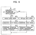
portable telephone 10 incorporating theinput device 1 will now be described. Referring to FIG. 6, in step 1 (ST1), a determination is made as to whether thedisplay 2 is in a state in which an operation corresponding to the individual input portions of theindicators 5 can be input. If thedisplay 2 is determined as being in that state (Yes) in step 1 (ST1), thecontroller 11 changes the setting to a single input mode (ST2). In the single input mode, it is possible to input information by simply pressing or touching one of theindicators 5 of thedetection members 4. Next, the process proceeds to step 3 (ST3), in which, when one of theindicators 5 of thedetection members 4 is pressed, an input signal that corresponds to the input portion of the pressedindicator 5. The process then proceeds to step 4 (ST4), in which the input signal is converted by thecontroller 11 into an operation signal that has been assigned to theindividual detection member 4, so that information displayed on thedisplay 2 is changed to an image in accordance with the operation signal. - On the other hand, in step 1 (ST1), when information displayed on the
display 2 does not correspond to an input portion (No), thecontroller 11 changes the setting into the motion input mode (ST5). In the motion input mode, an input operation that does not correspond to the input portion of theindicator 5 of eachdetection member 4 is possible. Next, the process proceeds to step 6 (ST6), in which continuously moving the finger from onedetection member 4 to anotherdetection member 4 causes the generation of an input signal. The process then proceeds to step 7 (ST7), in which the input signal is converted by thecontroller 11 into an operation signal as coordinate data. In that process, thecontroller 11 also computes a moving direction to generate the operation signal and information on thedisplay 2 is changed to an image in accordance with the operation signal. - As described above, the processes at steps ST1 to ST4 or at steps ST1 and ST5 to ST7 are repeated.
- The input device according to the present invention is not limited to the specific embodiment described above. For example, the display means may be provided on a housing other than the housing on which the input device is provided. Examples include a remote controller for a TV receiver. In this case, the single input mode allows channel switching of the TV receiver and the motion input mode allows menu selection displayed on the screen thereof.
- Alternatively, the input device according to the present invention may be used for a remote controller for equipment such as computers, audiovisual apparatuses, or other household electric appliances, or may be used with an operation panel directly incorporated in the body of such equipment.
- In addition, a dome-like inverting plate may be provided on the reverse side of the input portion of each
detection member 4 of theinput device 1, such that, when the surface of thedetection member 4 is pressed with a finger, the dome-like inverting plate is inverted. With this arrangement, a tactile feedback can be provided to the finger, thereby providing an operation sensation to the operator.
Claims (7)
- An input device which is controlled by a controller, the input device comprising:wherein the controller generates an operation signal in accordance with the switching-on or switching-off, anda plurality of detection members which are provided on an operating surface and which are switched on and off; andindicators which indicate corresponding input portions of the detection members,
wherein the controller allows a single input mode, in which operation of one of the detection members is processed as an operation input with respect to a corresponding one of the input portions, to be set, and allows a motion input mode, in which continuous operation of some of the detection members is processed as a motion operation input in accordance with the positional relationship of the operated detection members, to be set. - An input device which is controlled by a controller, the input device comprising:wherein the controller generates an operation signal in accordance with the operation of at least one of the detection members, anda plurality of detection members which are provided on an operating surface and which detect a contact and a movement of a manipulator; andindicators which indicate corresponding input portions of the detection members,
wherein the controller allows a single input mode, in which a touch of a manipulator on one of the detection members is processed as an operation input with respect to a corresponding one of the input portions, to be set, and allows a motion input mode, in which continuous movement of the manipulator across some of the detection members is processed as a motion operation input in accordance with the positional relationship of the operated detection members, to be set. - An input device according to claim 1 or 2, wherein the single input mode and the motion input mode are switched by external input using another input means that is provided on the detection member or the operating surface.
- An input device according to claim 1 or 2, wherein, in the state in which the motion input mode is set, when one of the detection members is operated, the controller recognizes the input portion of the operated detection member as a reference position and sets a plurality of the detection members that are adjacent to the operated detection member into a detectable state.
- An input device according to claim 4, wherein, subsequent to the operation of the detection member, when one of the detection members that are adjacent to the operated detection member is operated, the controller recognizes the input portion of the newly operated detection member as a new reference position and sets a plurality of the detection members that are adjacent to the newly operated detection member into a detectable state.
- An input device according to any preceding claim, wherein the input device is provided with display means, and in the setting of the motion input mode, the display means displays information in accordance with the motion input information resulting from the operation of the detection members.
- An input device according to claim 6, wherein the display means is provided on the same housing on which the detection members are provided, or is provided separately from the housing.
Applications Claiming Priority (2)
| Application Number | Priority Date | Filing Date | Title |
|---|---|---|---|
| JP2001068294A JP4383683B2 (en) | 2001-03-12 | 2001-03-12 | Input device |
| JP2001068294 | 2001-03-12 |
Publications (2)
| Publication Number | Publication Date |
|---|---|
| EP1246126A2 true EP1246126A2 (en) | 2002-10-02 |
| EP1246126A3 EP1246126A3 (en) | 2003-04-16 |
Family
ID=18926506
Family Applications (1)
| Application Number | Title | Priority Date | Filing Date |
|---|---|---|---|
| EP02251065A Withdrawn EP1246126A3 (en) | 2001-03-12 | 2002-02-16 | Input device capable of generating different input signals on single operating surface |
Country Status (3)
| Country | Link |
|---|---|
| US (1) | US20020126098A1 (en) |
| EP (1) | EP1246126A3 (en) |
| JP (1) | JP4383683B2 (en) |
Cited By (1)
| Publication number | Priority date | Publication date | Assignee | Title |
|---|---|---|---|---|
| FR2872598A1 (en) * | 2004-06-30 | 2006-01-06 | Clement Jeanjean | Multimedia electronic equipment e.g. multimedia platform, control device, has selection button to switch between remote control operation mode realized by touch screen and mouse usage mode realized by optical mouse type sensor |
Families Citing this family (5)
| Publication number | Priority date | Publication date | Assignee | Title |
|---|---|---|---|---|
| DE10345352A1 (en) * | 2003-09-18 | 2005-04-14 | E.G.O. Elektro-Gerätebau GmbH | Operating device and operating method for a household electrical appliance |
| JP2007065993A (en) * | 2005-08-31 | 2007-03-15 | Tokai Rika Co Ltd | Input apparatus |
| KR100689526B1 (en) * | 2005-10-07 | 2007-03-02 | 삼성전자주식회사 | Method for searching data in wireless terminal |
| KR101187579B1 (en) * | 2005-11-01 | 2012-10-02 | 삼성전자주식회사 | Terminal having display button and method of displaying using the display button |
| JP5082351B2 (en) * | 2006-09-08 | 2012-11-28 | 富士通モバイルコミュニケーションズ株式会社 | Mobile phone |
Citations (3)
| Publication number | Priority date | Publication date | Assignee | Title |
|---|---|---|---|---|
| EP0609021A2 (en) * | 1993-01-29 | 1994-08-03 | AT&T Corp. | Capacitive position sensor |
| US6072475A (en) * | 1996-08-23 | 2000-06-06 | Telefonaktiebolaget Lm Ericsson | Touch screen |
| WO2001000003A2 (en) * | 1999-06-22 | 2001-01-04 | Cirque Corporation | An improved touchpad |
Family Cites Families (5)
| Publication number | Priority date | Publication date | Assignee | Title |
|---|---|---|---|---|
| CA2157623C (en) * | 1994-09-20 | 1999-12-21 | Lars Stig Sorensen | Method and apparatus for dynamic radio communication menu |
| JP3508961B2 (en) * | 1995-07-21 | 2004-03-22 | ソニー株式会社 | Terminal device |
| JPH09233171A (en) * | 1996-02-26 | 1997-09-05 | Sony Corp | Communication terminal equipment |
| US6178338B1 (en) * | 1997-04-28 | 2001-01-23 | Sony Corporation | Communication terminal apparatus and method for selecting options using a dial shuttle |
| JPH11184611A (en) * | 1997-12-18 | 1999-07-09 | Mitsubishi Electric Corp | Character input display method using cursor key |
-
2001
- 2001-03-12 JP JP2001068294A patent/JP4383683B2/en not_active Expired - Fee Related
-
2002
- 2002-02-16 EP EP02251065A patent/EP1246126A3/en not_active Withdrawn
- 2002-03-06 US US10/092,232 patent/US20020126098A1/en not_active Abandoned
Patent Citations (3)
| Publication number | Priority date | Publication date | Assignee | Title |
|---|---|---|---|---|
| EP0609021A2 (en) * | 1993-01-29 | 1994-08-03 | AT&T Corp. | Capacitive position sensor |
| US6072475A (en) * | 1996-08-23 | 2000-06-06 | Telefonaktiebolaget Lm Ericsson | Touch screen |
| WO2001000003A2 (en) * | 1999-06-22 | 2001-01-04 | Cirque Corporation | An improved touchpad |
Cited By (1)
| Publication number | Priority date | Publication date | Assignee | Title |
|---|---|---|---|---|
| FR2872598A1 (en) * | 2004-06-30 | 2006-01-06 | Clement Jeanjean | Multimedia electronic equipment e.g. multimedia platform, control device, has selection button to switch between remote control operation mode realized by touch screen and mouse usage mode realized by optical mouse type sensor |
Also Published As
| Publication number | Publication date |
|---|---|
| JP2002268814A (en) | 2002-09-20 |
| JP4383683B2 (en) | 2009-12-16 |
| US20020126098A1 (en) | 2002-09-12 |
| EP1246126A3 (en) | 2003-04-16 |
Similar Documents
| Publication | Publication Date | Title |
|---|---|---|
| US7339577B2 (en) | Input device capable of button input and coordinate input on the same operating surface | |
| US7312790B2 (en) | Input apparatus for performing input operation corresponding to indication marks and coordinate input operation on the same operational plane | |
| JP4142720B2 (en) | Input device | |
| EP1691263B2 (en) | Display actuator | |
| US8773356B2 (en) | Method and apparatus for providing tactile sensations | |
| JP2002123363A5 (en) | ||
| US8077057B2 (en) | Input device with palm detecting unit | |
| US20070152975A1 (en) | Touch screen-type input device | |
| EP2469381A1 (en) | Selective rejection of touch contacts in an edge region of a touch surface | |
| JP2006004453A (en) | Touch operation type computer | |
| EP1246126A2 (en) | Input device capable of generating different input signals on single operating surface | |
| JP4288205B2 (en) | Coordinate input device | |
| JP2011134258A (en) | Input device and input control device including the same | |
| JP2006351219A (en) | Electronic apparatus | |
| JP4465231B2 (en) | Input device | |
| AU2015271962B2 (en) | Interpreting touch contacts on a touch surface | |
| JP2001236168A (en) | Keyboard and its device | |
| EP2735939A2 (en) | Keyboard |
Legal Events
| Date | Code | Title | Description |
|---|---|---|---|
| PUAI | Public reference made under article 153(3) epc to a published international application that has entered the european phase |
Free format text: ORIGINAL CODE: 0009012 |
|
| AK | Designated contracting states |
Kind code of ref document: A2 Designated state(s): AT BE CH CY DE DK ES FI FR GB GR IE IT LI LU MC NL PT SE TR |
|
| AX | Request for extension of the european patent |
Free format text: AL;LT;LV;MK;RO;SI |
|
| PUAL | Search report despatched |
Free format text: ORIGINAL CODE: 0009013 |
|
| AK | Designated contracting states |
Designated state(s): AT BE CH CY DE DK ES FI FR GB GR IE IT LI LU MC NL PT SE TR |
|
| AX | Request for extension of the european patent |
Extension state: AL LT LV MK RO SI |
|
| 17P | Request for examination filed |
Effective date: 20030404 |
|
| 17Q | First examination report despatched |
Effective date: 20030616 |
|
| AKX | Designation fees paid |
Designated state(s): DE GB |
|
| STAA | Information on the status of an ep patent application or granted ep patent |
Free format text: STATUS: THE APPLICATION IS DEEMED TO BE WITHDRAWN |
|
| 18D | Application deemed to be withdrawn |
Effective date: 20031028 |