EP1245985A2 - Image printing device with an optic of the Offner-type - Google Patents
Image printing device with an optic of the Offner-type Download PDFInfo
- Publication number
- EP1245985A2 EP1245985A2 EP02004367A EP02004367A EP1245985A2 EP 1245985 A2 EP1245985 A2 EP 1245985A2 EP 02004367 A EP02004367 A EP 02004367A EP 02004367 A EP02004367 A EP 02004367A EP 1245985 A2 EP1245985 A2 EP 1245985A2
- Authority
- EP
- European Patent Office
- Prior art keywords
- imaging device
- printing
- printing form
- mirror
- optical arrangement
- Prior art date
- Legal status (The legal status is an assumption and is not a legal conclusion. Google has not performed a legal analysis and makes no representation as to the accuracy of the status listed.)
- Granted
Links
Images


Classifications
-
- G—PHYSICS
- G02—OPTICS
- G02B—OPTICAL ELEMENTS, SYSTEMS OR APPARATUS
- G02B17/00—Systems with reflecting surfaces, with or without refracting elements
- G02B17/08—Catadioptric systems
- G02B17/0856—Catadioptric systems comprising a refractive element with a reflective surface, the reflection taking place inside the element, e.g. Mangin mirrors
- G02B17/086—Catadioptric systems comprising a refractive element with a reflective surface, the reflection taking place inside the element, e.g. Mangin mirrors wherein the system is made of a single block of optical material, e.g. solid catadioptric systems
-
- G—PHYSICS
- G02—OPTICS
- G02B—OPTICAL ELEMENTS, SYSTEMS OR APPARATUS
- G02B17/00—Systems with reflecting surfaces, with or without refracting elements
- G02B17/008—Systems specially adapted to form image relays or chained systems
-
- G—PHYSICS
- G02—OPTICS
- G02B—OPTICAL ELEMENTS, SYSTEMS OR APPARATUS
- G02B17/00—Systems with reflecting surfaces, with or without refracting elements
- G02B17/08—Catadioptric systems
- G02B17/0804—Catadioptric systems using two curved mirrors
- G02B17/0808—Catadioptric systems using two curved mirrors on-axis systems with at least one of the mirrors having a central aperture
-
- G—PHYSICS
- G02—OPTICS
- G02B—OPTICAL ELEMENTS, SYSTEMS OR APPARATUS
- G02B17/00—Systems with reflecting surfaces, with or without refracting elements
- G02B17/08—Catadioptric systems
- G02B17/082—Catadioptric systems using three curved mirrors
- G02B17/0824—Catadioptric systems using three curved mirrors on-axis systems with at least one of the mirrors having a central aperture
-
- G—PHYSICS
- G02—OPTICS
- G02B—OPTICAL ELEMENTS, SYSTEMS OR APPARATUS
- G02B17/00—Systems with reflecting surfaces, with or without refracting elements
- G02B17/08—Catadioptric systems
- G02B17/0884—Catadioptric systems having a pupil corrector
-
- G—PHYSICS
- G03—PHOTOGRAPHY; CINEMATOGRAPHY; ANALOGOUS TECHNIQUES USING WAVES OTHER THAN OPTICAL WAVES; ELECTROGRAPHY; HOLOGRAPHY
- G03F—PHOTOMECHANICAL PRODUCTION OF TEXTURED OR PATTERNED SURFACES, e.g. FOR PRINTING, FOR PROCESSING OF SEMICONDUCTOR DEVICES; MATERIALS THEREFOR; ORIGINALS THEREFOR; APPARATUS SPECIALLY ADAPTED THEREFOR
- G03F7/00—Photomechanical, e.g. photolithographic, production of textured or patterned surfaces, e.g. printing surfaces; Materials therefor, e.g. comprising photoresists; Apparatus specially adapted therefor
- G03F7/70—Microphotolithographic exposure; Apparatus therefor
- G03F7/70216—Mask projection systems
- G03F7/70275—Multiple projection paths, e.g. array of projection systems, microlens projection systems or tandem projection systems
Definitions
- the invention relates to an imaging device for a printing form with an array of light sources and a subordinate micro-optics, which create a virtual image of the Generates light sources.
- the use of light source arrays in rows or in matrix form for imaging Printing forms places high demands on the imaging optics to be used.
- the light source arrays consist of a certain number of Diode lasers, preferably single-mode lasers, which are at a certain distance from one another, typically substantially equally spaced, on a semiconductor substrate are arranged and which exactly over a common over the crystal fracture plane defined exit level.
- the light emission cones of these light sources or Diode lasers are essentially orthogonal to each other in the two Levels of symmetry opened to different degrees.
- a number of imaging optics are known from the prior art, which specifically realized for the imaging of diode laser rows for imaging an image carrier were.
- a semiconductor laser array is known from US 4,428,647 individual lasers each have a nearby lens between the laser array and Objective lens is assigned. The purpose of these lenses is to get the divergence angle out to change the surface of the laser array emerging light beams such that the Light is collected as efficiently as possible through the objective lens and onto an image carrier is focused.
- the refractive power of these lenses is selected in such a way that one for each laser virtual intermediate image is generated behind the emitting surface, its distances correspond approximately to the distances between the emitted light beams, the Emitter intermediate image is enlarged.
- EP 0 694 408 B1 describes how a micro-optic can be used axially symmetric optical elements a reduction in the divergence of the emerging Light can be achieved.
- From US 3,748,015 is an optical system for forming an image of an object known with unit magnification and high resolution, which an arrangement of a includes convex and concave spherical mirror whose Centers of curvature coincide at one point. This mirror arrangement creates at least three reflection points within the system and creates two of them conjugate areas spaced apart by optical axis with unit magnification in one Plane that contains the center of curvature, where the optical axis of the system is orthogonal to this plane at the center of curvature.
- Such a combination of mirrors is free from spherical aberration, coma and distortion and when the algebraic sum of the strengths or refractive powers of the reflective used Is 0, the image generated is free of astigmatism and Third-order field curvature.
- Such an optical system is called an optical Designated from the Opener type.
- the imaging optics described in this document for a plurality of individually controllable diode lasers include an arrangement of spherical ones Mirroring of the Offner type described above, i.e. a combination of spherical Concave and convex mirrors with a common center of curvature, but from the divergence-reducing micro-optics not a virtual one, especially an enlarged one Intermediate image generated.
- an imaging device for a printing form in a printing platesetter or a printing unit in a printing press requires additional measures.
- the installation space in such machines is very limited, on the other hand, too on the structure or configuration of the platesetter or the printing unit for the implementation of an imaging device can be changed little a reduction in the installation space required.
- one Imaging optics on a printing press or a printing platesetter or exposed to vibrations so that it should have as few parts as possible which must be adjusted relative to each other, so that known from the prior art optical arrangements not easy for use on a printing platesetter or can be transmitted within a printing unit of a printing press.
- the present invention has for its object an imaging optics for a To create an array of light sources so that an easy reduction in the divergence of the emitted light and an image with low aberrations is made possible.
- Imaging optics for an imaging device for a printing form are also intended with the smallest possible installation space and as few parts as possible, therefore as possible few degrees of freedom of adjustment can be realized.
- Imaging device with the features according to Claim 1 solved.
- Advantageous embodiments and developments of Imaging device according to the invention are characterized in the subclaims.
- the imaging device for a printing form with an array of Light sources and a subordinate micro-optics, which a virtual image of the Generates light sources is characterized by the fact that the micro-optics are optical Arrangement comprising at least one sector of a concave mirror and one sector of a Includes convex mirror with a common center of curvature, preferably the algebraic sum of the powers of the refractive powers is 0, in other words macro optics or combination of the offner type, which is a real picture of the virtual Intermediate image generated.
- each light source of the array via virtual intermediate image of the microscopic requirements, in particular the Divergence adjusted.
- a subordinate macroscopic image using known properties of an optical arrangement of the Opener type that is, one Combination of at least one sector of a convex mirror and one sector of one Concave mirror with a common center of curvature allows an advantageous Imaging points along a line that is essentially circular.
- the optical arrangement, which is subordinate to the micro-optics as macro-optics, the Imaging device according to the invention is designed such that the virtual Intermediate pixels of the light sources, which are essentially arranged in a row are a short distance from this circular line.
- the Imaging device enables a constant emission correction a large number of light sources, in particular diode lasers, with a small number optical elements.
- a combination of cylindrical lenses creates a micro-optical Symmetry with simultaneous enlargement using a virtual intermediate image each light source and an aberration-free image of this virtual one Intermediate images in a real image by means of a subordinate optical arrangement of a Convex mirror and a concave mirror becomes an imaging device for one Printing form created with particularly advantageous imaging properties.
- the Micro-optics are preferably aspherical.
- it can be Act cylindrical lenses or a combination of anamorphic prisms.
- the Subordinate macroscopic optical arrangement of a convex mirror and one Concave mirror has at least one circular segment of a rotationally symmetrical optic on whose assigned object circle line is essentially straight running projection of the row of virtual intermediate pixels a low held distance, the object circle within one of the two conjugated areas of the optical arrangement of a convex mirror and one Concave mirror.
- This makes it possible by means of the optical arrangement of the Offner type the row of the virtual intermediate image points in FIG to actually image the second conjugate area with unit magnification.
- the freedom from aberrations of the optical arrangement of a convex mirror is advantageous and a concave mirror.
- the imaging device it is advantageous to at least fold the beam path within the optical Arrange a convex mirror and a concave mirror. It is therefore advantageous to have at least one light deflecting surface in the micro-optics subordinate optical arrangement, be it before and / or after the reflective surfaces of the optical arrangement of a convex mirror and a concave mirror provided.
- the beam path through the imaging optics of the invention Imaging device compact, so that for an implementation within a Printing platesetter or a printing unit a reduction in installation space is possible.
- the monolithic structure from a suitable material with a refractive index different from the environment, for example from a glass or another transparent material.
- the individual component or the monolith can then have partially inwardly mirrored surfaces, for example the concave or convex reflective surface of the optical arrangement of a convex mirror and a concave mirror. These inner surfaces are also called active inner ones Surfaces of the monolith.
- the monolithic structure further optical elements, such as prisms or light deflection surfaces for beam deflection be assigned.
- An imaging device can be particularly advantageous in one Printing platesetter or in a printing unit.
- a Printing machine according to the invention which has a feeder, at least one printing unit and comprises a delivery arm, characterized in that this printing machine at least has a printing unit with an imaging device according to the invention.
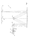
- FIG. 1 shows a schematic illustration of a configuration of optical elements in FIG an embodiment of the imaging device according to the invention for a Printing form.
- the imaging device according to the invention has a light source 12 an associated micro-optics 14 and a subordinate optical arrangement 10.
- the Divergent light 16 emitted by the light source 12 is turned on by the micro-optics 14 virtual image 18 shown. Due to the downstream optical arrangement 10 Light rays 20 starting from the virtual intermediate image 18 via various optical Elements transformed into a real pixel 28.
- the optical arrangement 10 points in this embodiment, first a deflecting element 22 and one along the optical Axis 23 and, in addition, a rotationally symmetrical pair of mirrors, the Concave mirror 24 and the convex mirror 26 with a common center of curvature 25 along the optical axis 23.
- This consists of concave mirror 24 and convex mirror 26 pair formed forms points in one item area on points in one Image area. These areas are conjugated to each other.
- the additional Deflection element 22 is the symmetry of the beam path through the optical arrangement 10 broken, so that the pixel 28 as the conjugate point is the virtual intermediate image 18 and not the conjugate point without deflection element 27 in the printing form plane 29 assigned.
- the optical path length between the virtual intermediate image 18 and the But concave mirror 24 is equal to the optical length between concave mirror 24 and Pixel 28 in the printing form plane 29.
- FIG. 1 While in FIG. 1 the image of a light source 12 with micro-optics 14 and a subordinate optical arrangement 10, i.e. a macro optic, for drawing a better understanding of the imaging device according to the invention is shown a plurality by means of a corresponding preferred embodiment of the invention of light sources 12, which are typically arranged in series, by a preferably for each light source 12 individually shaped micro optics 14 and one on the A plurality of the intermediate images 18 acting macro optics, the optical arrangement 10 one Convex mirror and a concave mirror corresponding, shown.
- the optical arrangement 10 one Convex mirror and a concave mirror corresponding, shown.
- FIG. 2 shows a schematic illustration of a configuration of optical elements in FIG an alternative embodiment of the imaging device according to the invention for a printing form with an additional beam profile filter shown.
- the invention Imaging device comprises a light source 12, a micro-optic 14 Entry window 32 into an encapsulation 33 in which the optical arrangement 10 is located, and an exit window 34 with downstream printing form 29.
- the optical Arrangement 10 comprises a deflection element 22, a concave mirror 24 Wavefront correction element or beam shaping element 30, a so-called Beam profile filter, preferably for transmission of the fundamental mode of the light source 12, for example with a Gaussian beam profile, and a concave mirror 26.
- Die Optical arrangement 10 is therefore also a convex mirror and a concave mirror with conjugated areas, the virtual intermediate image 18, generated from the divergent light 16 of the light source 12 by means of the micro-optics 14, in the first conjugate Area and the pixel 28 in the printing form plane 29 in the second conjugate Area.
- the Deflection element 22 be it in front of the convex mirror 26, as shown here in FIG. 2, crossing the beam path between convex mirror 26 and concave mirror 24, or alternatively past the convex mirror it is possible to make one even more compact To achieve construction.
- FIG. 3 is used with a schematic representation to explain the location of a Focal line, i.e. H. selected points in the first conjugate area of the optical Arrangement of a convex mirror and a concave mirror to the row of virtual ones Pixels of the array of light sources.
- a projection along is shown in FIG the optical axis 23 of the concave mirror 24 and the convex mirror 26 of the optical Arrangement 10.
- the substantially circular focal line 36 represents the Projection of the conjugate areas onto the concave mirror 24 in the case of one here exemplary chosen symmetrical beam path.
- Object point and pixel of the optical arrangement of a convex mirror and of a concave mirror are essentially opposite in phase on a circular one Focal line 36, i.e.
- the focal line 36 essentially describes those points with extremely beneficial Transformation property, i.e. with minimized aberrations.
- the goal now is the row of the virtual pixels 38 of this focal line 36 as close as possible. It is in the Connection of the invention is irrelevant which exact metric or which measure for Measurement of the distance of the line 38 to the circular segment 36 is selected. exemplary the average distance of the light sources in the projection 38 to the optical axis 23, the sum of the distances divided by the number of light sources, as a measure be used.
- the distance of the projection of the series of virtual Pixels 38 are kept low or adapted to the radius of the focal line 36.
- the optical arrangement 10 of a convex mirror and one Concave mirror should be designed such that the projection of the focal line 36 one has the largest possible radius of curvature.
- the focal line 36 should be compared to Projection of the row of light sources 38 run as flat as possible.
- the one used Optical arrangement 10 therefore only needs at least one segment of a circle rotationally symmetrical optics of a convex mirror and a concave mirror exhibit.
- FIG. 4 is a schematic illustration of a monolithic structure Embodiment of the optical arrangement in the invention Imaging device shown.
- a monolithic structure is said to be another Reduction of the optical arrangement of a convex mirror and a concave mirror can be achieved.
- Shown in FIG. 4 is an example to explain such monolithic structure a symmetrical beam path.
- the optical arrangement 10 is symmetrical to axis 41. Starting from the virtual intermediate image 18, this is not the case here
- the light source shown, in addition to micro-optics, light rays 20 pass through an entrance window 32 into a monolith 40, which is made, for example, of a high-index glass or a there is transparent polymer for the wavelength used.
- the monolith has one Concave surface 42, which reflects the light rays 20, so that they are in a Essentially planar mirror surface 46 meet concave surface 42. Of the mirror surface 46, the rays are thrown onto a convex surface 44, from which proceeding symmetrically on the other side of the axis of symmetry 41 in turn Mirror surface 46 and then the concave surface 42 hit by the light rays until it leaves the monolith through an exit window 34 and into one Pixel 28, expediently in the printing form plane, not shown here, converge.
- the monolithic structure as shown in this FIG.
- the convex surface 44 corresponds to a convex mirror on the Position 48, on which the light rays 20 along the light paths 50 without a reflective surface 46 would hit. While the sides of the monolith 40 on which the light rays 20 should be reflected by suitable coatings, be it through a metal layer or by using interference filters, as reflective as possible, is for the entrance window 32 and / or the exit window 34 an anti-reflective coating, for example by a Interference filter, provided so that the strongest possible coupling or decoupling of the Light in or out of the monolith is made possible.
- FIG. 5 is a schematic illustration of a monolithic design alternative optical arrangement of a convex mirror and a concave mirror below Utilization of two-beam folds shown.
- a light source 12 is by means of a Micro-optics 14 transformed into a virtual intermediate image 18.
- the one from this virtual Intermediate image 18 outgoing light rays 20 enter the monolith 40 and are on a first deflection surface 51 and a second deflection surface 52 Concave surface 42 projected.
- the light rays 20 then hit a mirror surface 46, on a convex surface 44, again on the mirror surface 46 and on the concave surface 42, to then exit the monolith 40 through an exit window 34 and in a Pixel 28 to converge.
- a symmetrical alternative optical image of a convex mirror and a concave mirror is shown schematically in FIG. 6, with additional Deflection elements can be used in prismatic form.
- From the virtual intermediate picture 18 outgoing light rays 20 of the light source 12 not shown here enter prismatic deflection element 54, at the base of which they are reflected, and arrive in the monoliths 40.
- a symmetrical beam path is provided, the light beams 20 first meet a concave surface 42, a mirror surface 46, a convex surface, again on the mirror surface 46 and on the concave surface 42 a prismatic deflection element 54 is provided, at the base of which the light rays 20 total be reflected. The light converges into a pixel 28.
- FIG. 7 shows a schematic representation of a further alternative monolithic executed optical arrangement of a convex mirror and a concave mirror with an additional convex sphere and a prism for coupling the shown light.
- That of a virtual intermediate image 18, but not one here Light source shown together with micro-optics Light 20 enters a prism 58 and from there into a convex sphere 56.
- An area is provided in the surface thereof through which the Light rays 20 can enter the monoliths 40 with as little reflection as possible.
- the Light rays 20 are reflected on the various inner surfaces of the monolith. This Inner surfaces include the facet 60, a concave surface 42, a mirror surface 46 and a convex surface 44.
- the beam path of the light 20 is up to the pixel 28 indicated.
- the light can exit the monolith 40 through an exit window 34.
- the convex surface 44 is mirrored so that light within the Monolith 40 is reflected.
Abstract
Description
Die Erfindung betrifft eine Bebilderungseinrichtung für eine Druckform mit einem Array von Lichtquellen und einer nachgeordneten Mikrooptik, welche ein virtuelles Bild der Lichtquellen erzeugt.The invention relates to an imaging device for a printing form with an array of light sources and a subordinate micro-optics, which create a virtual image of the Generates light sources.
Der Einsatz von Lichtquellenarrays in Reihen oder in Matrixform zur Bebilderung von Druckformen, sei es in einem Druckformbelichter oder in einem Direct Imaging Druckwerk, stellt hohe Anforderungen an die zu verwendende Abbildungsoptik. Typischerweise bestehen die Lichtquellenarrays aus einer bestimmten Anzahl von Diodenlasern, bevorzugt Single-Mode-Lasern, welche in bestimmtem Abstand zueinander, typischerweise im Wesentlichen gleich beabstandet, auf einem Halbleitersubstrat angeordnet sind und welche über eine gemeinsame über die Kristallbruchebene genau definierte Austrittsebene verfügen. Die Lichtemissionskegel dieser Lichtquellen oder Diodenlaser sind in den zwei zueinander im Wesentlichen orthogonal stehenden Symmetrieebenen unterschiedlich weit geöffnet. Daraus ergibt sich die Notwendigkeit einer Abbildungsoptik, welche einerseits diese Asymmetrie mit einer bevorzugt geringen Anzahl von Baugruppen verringert, bevorzugt minimiert, und andererseits eine möglichst abbildungsfehlerfreie globale Abbildung des Arrays von Emittern ermöglicht.The use of light source arrays in rows or in matrix form for imaging Printing forms, be it in a printing platesetter or in direct imaging Printing unit, places high demands on the imaging optics to be used. Typically, the light source arrays consist of a certain number of Diode lasers, preferably single-mode lasers, which are at a certain distance from one another, typically substantially equally spaced, on a semiconductor substrate are arranged and which exactly over a common over the crystal fracture plane defined exit level. The light emission cones of these light sources or Diode lasers are essentially orthogonal to each other in the two Levels of symmetry opened to different degrees. Hence the need imaging optics, which on the one hand have this asymmetry with a preferably low Number of assemblies reduced, preferably minimized, and on the other hand one possible Imaging-free global mapping of the array of emitters enabled.
Aus dem Stand der Technik ist eine Reihe von Abbildungsoptiken bekannt, welche speziell für die Abbildung von Diodenlaserreihen zur Bebilderung eines Bildträgers realisiert wurden. Beispielsweise ist aus der US 4,428,647 ein Halbleiterlaserarray bekannt, dessen einzelnen Lasern jeweils eine in der Nähe befindliche Linse zwischen Laserarray und Objektivlinse zugeordnet ist. Der Zweck dieser Linsen ist, den Divergenzwinkel, der aus der Oberfläche des Laserarrays austretenden Lichtstrahlen derart zu verändern, dass das Licht möglichst effizient durch die Objektivlinse gesammelt und auf einen Bildträger fokussiert wird. Die Brechkraft dieser Linsen ist derart gewählt, dass fiir jeden Laser ein virtuelles Zwischenbild hinter der emittierenden Oberfläche erzeugt wird, deren Abstände ungefähr den Abständen der emittierten Lichtstrahlen entsprechen, wobei das Emitterzwischenbild vergrößert ist.A number of imaging optics are known from the prior art, which specifically realized for the imaging of diode laser rows for imaging an image carrier were. For example, a semiconductor laser array is known from US 4,428,647 individual lasers each have a nearby lens between the laser array and Objective lens is assigned. The purpose of these lenses is to get the divergence angle out to change the surface of the laser array emerging light beams such that the Light is collected as efficiently as possible through the objective lens and onto an image carrier is focused. The refractive power of these lenses is selected in such a way that one for each laser virtual intermediate image is generated behind the emitting surface, its distances correspond approximately to the distances between the emitted light beams, the Emitter intermediate image is enlarged.
In der EP 0 694 408 B 1 wird zum Beispiel beschrieben, wie eine Mikrooptik mittels axialsymmetrischen optischen Elementen eine Reduktion der Divergenz des austretenden Lichtes erreicht werden kann.EP 0 694 408 B1, for example, describes how a micro-optic can be used axially symmetric optical elements a reduction in the divergence of the emerging Light can be achieved.
Der oft außergewöhnliche große Unterschied in den lateralen Felddimensionen eines derartigen Lichtquellenarrays, beispielsweise 10 x 0,001 mm2, erfordert daher eine spezifische mikroskopische und makroskopische Abbildung. Eine Verwendung von sphärischer Optik für diese Dimensionen ist nur mit einem relativ großen und aufwendigen Optikdesign lösbar. Nachteilig bei der Verwendung sphärischer Makrooptik ist die variable Abbildungsqualität als Funktion des Abstandes zur optischen Achse. Auch der Einsatz von Zylinderlinsen und Zylinderlinsenarrays hat bislang nicht eine Abbildung eines Lichtquellenarrays, insbesondere in Form einer Diodenlaserreihe in gewünschter konstanter Qualität erbracht.The often extraordinary large difference in the lateral field dimensions of such a light source array, for example 10 × 0.001 mm 2 , therefore requires a specific microscopic and macroscopic image. The use of spherical optics for these dimensions can only be solved with a relatively large and complex optical design. The disadvantage of using spherical macro-optics is the variable imaging quality as a function of the distance from the optical axis. The use of cylindrical lenses and cylindrical lens arrays has so far not produced an image of a light source array, in particular in the form of a row of diode lasers, in the desired constant quality.
Aus der US 3,748,015 ist ein optisches System zur Formung eines Bildes eines Objektes mit Einheitsvergrößerung und hoher Auflösung bekannt, welche eine Anordnung eines konvexen und eines konkaven sphärischen Spiegels umfasst, deren Krümmungsmittelpunkte an einem Punkt zusammenfallen. Diese Spiegelanordnung erzeugt wenigstens drei Reflexionspunkte innerhalb des Systems und erzeugt zwei von der optischen Achse beabstandete konjugierte Bereiche mit Einheitsvergrößerung in einer Ebene, welche den Krümmungsmittelpunkt enthält, wobei die optische Achse des Systems orthogonal zu dieser Ebene im Krümmungsmittelpunkt ist. Eine derartige Kombination von Spiegeln ist frei von Sphärischer Aberration, Koma und Verzeichnung und, wenn die algebraische Summe der Stärken oder Brechkräfte der benutzten reflektierenden Spiegeloberflächen 0 ist, ist das erzeugte Bild frei von Astigmatismus und Bildfeldwölbung in dritter Ordnung. Eine derartige optisches System wird als optische Anordnung vom Offner-Typ bezeichnet. From US 3,748,015 is an optical system for forming an image of an object known with unit magnification and high resolution, which an arrangement of a includes convex and concave spherical mirror whose Centers of curvature coincide at one point. This mirror arrangement creates at least three reflection points within the system and creates two of them conjugate areas spaced apart by optical axis with unit magnification in one Plane that contains the center of curvature, where the optical axis of the system is orthogonal to this plane at the center of curvature. Such a combination of mirrors is free from spherical aberration, coma and distortion and when the algebraic sum of the strengths or refractive powers of the reflective used Is 0, the image generated is free of astigmatism and Third-order field curvature. Such an optical system is called an optical Designated from the Opener type.
In diesem Zusammenhang sei erwähnt, dass beispielsweise in der US 5,592,444 eine Methode mit einer zugehörigen Vorrichtung zum Schreiben und Lesen von Daten auf einem optischen Speichermedium simultan in einer Mehrzahl von Spuren beschrieben wird. Die in diesem Dokument beschriebene Abbildungsoptik für eine Mehrzahl von einzeln ansteuerbaren Diodenlasern umfasst dabei eine Anordnung von sphärischen Spiegeln vom oben beschriebenen Offner-Typ, also eine Kombination aus sphärischen Konkav- und Konvexspiegel mit gemeinsamem Krümmungsmittelpunkt, jedoch wird von der Divergenz reduzierenden Mikrooptik kein virtuelles, insbesondere vergrößertes Zwischenbild erzeugt.In this context it should be mentioned that, for example, in US 5,592,444 Method with an associated device for writing and reading data an optical storage medium simultaneously written in a plurality of tracks becomes. The imaging optics described in this document for a plurality of individually controllable diode lasers include an arrangement of spherical ones Mirroring of the Offner type described above, i.e. a combination of spherical Concave and convex mirrors with a common center of curvature, but from the divergence-reducing micro-optics not a virtual one, especially an enlarged one Intermediate image generated.
Der Einsatz einer Bebildungseinrichtung für eine Druckform in einem Druckformbelichter oder einem Druckwerk in einer Druckmaschine erfordert jedoch zusätzliche Maßnahmen. Da zum einen der Bauraum in derartigen Maschinen sehr begrenzt ist, zum anderen auch am Aufbau oder an der Konfiguration des Druckformbelichters oder des Druckwerkes für die Implementierung einer Bebilderungseinrichtung wenig abgeändert werden kann, ist eine Reduzierung des benötigten Bauraumes erforderlich. Des Weiteren ist eine Abbildungsoptik an einer Druckmaschine oder einem Druckformbelichter Erschütterungen oder Vibrationen ausgesetzt, sodass sie möglichst wenig Teile aufweisen sollte, welche relativ zueinander justiert werden müssen, sodass aus dem Stand der Technik bekannte optische Anordnungen nicht einfach für die Verwendung an einem Druckformbelichter oder innerhalb eines Druckwerkes einer Druckmaschine übertragen werden können.The use of an imaging device for a printing form in a printing platesetter or a printing unit in a printing press, however, requires additional measures. On the one hand, the installation space in such machines is very limited, on the other hand, too on the structure or configuration of the platesetter or the printing unit for the implementation of an imaging device can be changed little a reduction in the installation space required. Furthermore, one Imaging optics on a printing press or a printing platesetter or exposed to vibrations so that it should have as few parts as possible which must be adjusted relative to each other, so that known from the prior art optical arrangements not easy for use on a printing platesetter or can be transmitted within a printing unit of a printing press.
Der vorliegenden Erfindung liegt die Aufgabe zugrunde, eine Abbildungsoptik für ein Array von Lichtquellen zu schaffen, sodass eine einfache Verringerung der Divergenz des emittierten Lichtes und eine Abbildung mit geringen Aberrationen ermöglicht wird. Des Weiteren soll eine Abbildungsoptik für eine Bebilderungseinrichtung für eine Druckform mit möglichst geringem Bauraumbedarf und möglichst wenig Teilen, daher möglichst wenig Freiheitsgraden der Justage realisiert werden. The present invention has for its object an imaging optics for a To create an array of light sources so that an easy reduction in the divergence of the emitted light and an image with low aberrations is made possible. Of Imaging optics for an imaging device for a printing form are also intended with the smallest possible installation space and as few parts as possible, therefore as possible few degrees of freedom of adjustment can be realized.
Diese Aufgabe wird durch eine Bebilderungseinrichtung mit den Merkmalen gemäß Anspruch 1 gelöst. Vorteilhafte Ausführungsformen und Weiterbildungen der erfindungsgemäßen Bebilderungseinrichtung sind in den Unteransprüchen charakterisiert.This task is performed by an imaging device with the features according to Claim 1 solved. Advantageous embodiments and developments of Imaging device according to the invention are characterized in the subclaims.
Die erfindungsgemäße Bebilderungseinrichtung für eine Druckform mit einem Array von Lichtquellen und einer nachgeordneten Mikrooptik, welche ein virtuelles Bild der Lichtquellen erzeugt, zeichnet sich dadurch aus, dass der Mikrooptik eine optische Anordnung, welche wenigstens einen Sektor eines Konkavspiegels und einen Sektor eines Konvexspiegels mit gemeinsamen Krümmungsmittelpunkt umfasst, wobei bevorzugt die algebraische Summe der Stärken der Brechkräfte 0 ist, in anderen Worten eine Makrooptik oder Kombination vom Offner-Typ, nachgeordnet ist, welche ein reelles Bild des virtuellen Zwischenbildes erzeugt. In der Folge wird auch vereinfachend von einer Anordnung eines Konvexspiegels und Konkavspiegels gesprochen, obschon auch wenigstens ein Spiegel nur einen Sektor, welcher sowohl eine einfach als auch nicht-einfach zusammenhängende Fläche definieren kann, in einen bestimmten Teilraumwinkelbereich von maximal 4π aufweisen kann. Die Krümmungsmittelpunkte des Konkavspiegels und des Konvexspiegels müssen dabei in der Realität einer bestimmten Ausführungsform nicht völlig exakt aufeinander liegen, um die gewünschten Eigenschaften der optischen Anordnung vom Offner-Typ in ausreichender Genauigkeit zum Einsatz in einer erfindungsgemäßen Bebilderungseinrichtung zu erlangen.The imaging device according to the invention for a printing form with an array of Light sources and a subordinate micro-optics, which a virtual image of the Generates light sources is characterized by the fact that the micro-optics are optical Arrangement comprising at least one sector of a concave mirror and one sector of a Includes convex mirror with a common center of curvature, preferably the algebraic sum of the powers of the refractive powers is 0, in other words macro optics or combination of the offner type, which is a real picture of the virtual Intermediate image generated. As a result, an arrangement of a Convex mirror and concave mirror spoken, although at least one mirror only a sector that is both simple and non-simply related Can define area in a certain partial solid angle range of maximum 4π can have. The centers of curvature of the concave mirror and the Convex mirrors do not have to be in the reality of a specific embodiment lie exactly on top of each other to achieve the desired properties of the optical Opener-type arrangement with sufficient accuracy for use in a to obtain imaging device according to the invention.
Unter Einsatz einer geringen Anzahl von optisch refraktiven Flächen wird in der erfindungsgemäßen Bebilderungseinrichtung jede Lichtquelle des Arrays über ein virtuelles Zwischenbild den mikroskopischen Anforderungen, also insbesondere der Divergenz angepasst. Eine nachgeordnete makroskopische Abbildung unter Ausnutzung bekannter Eigenschaften einer optischen Anordnung vom Offner-Typ, also eine Kombination wenigstens eines Sektors eines Konvexspiegels und eines Sektors eines Konkavspiegels mit gemeinsamen Krümmungsmittelpunkt, erlaubt eine vorteilhafte Abbildung von Punkten entlang einer Linie, welche im wesentlichen kreisförmig verläuft. Die optische Anordnung, welcher der Mikrooptik als Makrooptik nachgeordnet ist, der erfindungsgemäßen Bebilderungseinrichtung ist dabei derart ausgeführt, dass die virtuellen Zwischenbildpunkte der Lichtquellen, welche im Wesentlichen auf einer Reihe angeordnet sind, einen geringen Abstand zu dieser Kreislinie aufweisen. Mit anderen Worten: Die erfindungsgemäße Bebilderungseinrichtung ermöglicht eine konstante Emissionskorrektur einer Vielzahl von Lichtquellen, insbesondere Diodenlasern, mit einer geringen Anzahl optischer Elemente. Durch eine Kombination von Zylinderlinsen wird eine mikrooptische Symmetriesierung bei gleichzeitiger Vergrößerung mittels eines virtuellen Zwischenbildes jeder Lichtquelle und eine möglichst aberrationsfreie Abbildung dieser virtuellen Zwischenbilder in ein reelles Bild mittels einer nachgeordneten optischen Anordnung eines Konvexspiegels und eines Konkavspiegels wird eine Bebilderungseinrichtung für eine Druckform mit besonders vorteilhaften Abbildungseigenschaften geschaffen.Using a small number of optically refractive surfaces in the Imaging device according to the invention each light source of the array via virtual intermediate image of the microscopic requirements, in particular the Divergence adjusted. A subordinate macroscopic image using known properties of an optical arrangement of the Opener type, that is, one Combination of at least one sector of a convex mirror and one sector of one Concave mirror with a common center of curvature allows an advantageous Imaging points along a line that is essentially circular. The optical arrangement, which is subordinate to the micro-optics as macro-optics, the Imaging device according to the invention is designed such that the virtual Intermediate pixels of the light sources, which are essentially arranged in a row are a short distance from this circular line. In other words: the Imaging device according to the invention enables a constant emission correction a large number of light sources, in particular diode lasers, with a small number optical elements. A combination of cylindrical lenses creates a micro-optical Symmetry with simultaneous enlargement using a virtual intermediate image each light source and an aberration-free image of this virtual one Intermediate images in a real image by means of a subordinate optical arrangement of a Convex mirror and a concave mirror becomes an imaging device for one Printing form created with particularly advantageous imaging properties.
Zu einer Anpassung der Divergenz des emittierten Lichtes der Lichtquellen ist die Mikrooptik bevorzugt asphärisch ausgeführt. Beispielsweise kann es sich dabei um Zylinderlinsen oder eine Kombination anamorphotischer Prismen handeln. Die nachgeordnete makroskopische optische Anordnung eines Konvexspiegels und eines Konkavspiegels weist wenigstens ein Kreissegment einer rotationssymmetrischen Optik auf, zu deren zugeordneter Gegenstandskreislinie die im Wesentlichen gradlinig verlaufenden Projektion der Reihe der virtuellen Zwischenbildpunkte einen gering gehaltenen Abstand aufweist, wobei die Gegenstandskreislinie innerhalb eines der zwei konjugierten Bereiche der optischen Anordnung eines Konvexspiegels und eines Konkavspiegels liegt. Damit ist es möglich, mittels der optischen Anordnung vom Offner-Typ die im Wesentlichen gradlinig verlaufende Reihe der virtuellen Zwischenbildpunkte in den zweiten konjugierten Bereich reell mit Einheitsvergrößerung abzubilden. Besonders vorteilhaft ist dabei die Aberrationsfreiheit der optischen Anordnung eines Konvexspiegels und eines Konkavspiegels.To adjust the divergence of the emitted light from the light sources is the Micro-optics are preferably aspherical. For example, it can be Act cylindrical lenses or a combination of anamorphic prisms. The Subordinate macroscopic optical arrangement of a convex mirror and one Concave mirror has at least one circular segment of a rotationally symmetrical optic on whose assigned object circle line is essentially straight running projection of the row of virtual intermediate pixels a low held distance, the object circle within one of the two conjugated areas of the optical arrangement of a convex mirror and one Concave mirror. This makes it possible by means of the optical arrangement of the Offner type the row of the virtual intermediate image points in FIG to actually image the second conjugate area with unit magnification. Especially The freedom from aberrations of the optical arrangement of a convex mirror is advantageous and a concave mirror.
Zur Verringerung des Bauraumbedarfs der erfindungsgemäßen Bebilderungseinrichtung ist es vorteilhaft, wenigstens eine Faltung des Strahlengangs innerhalb der optischen Anordnung eines Konvexspiegels und eines Konkavspiegels vorzunehmen. Vorteilhafterweise wird daher wenigstens eine Lichtumlenkfläche in der der Mikrooptik nachgeordneten optischen Anordnung, sei es vor und/oder nach den reflektiven Flächen der optischen Anordnung eines Konvexspiegels und eines Konkavspiegels vorgesehen. Dadurch wird der Strahlengang durch die Abbildungsoptik der erfindungsgemäßen Bebilderungseinrichtung kompakt, sodass für eine Realisierung innerhalb eines Druckformbelichters oder eines Druckwerkes eine Bauraumverringerung möglich ist. Darüber hinaus kann mit besonderem Vorteil die Gestaltung wenigstens eines Teils der optischen Anordnung eines Konvexspiegels und eines Konkavspiegels als ein einzelnes Bauteil, also monolithisch aus einem geeigneten Material mit einem Brechungsindex verschieden von der Umgebung, beispielsweise aus einem Glas oder einem anderen transparenten Material, vorgenommen werden. Das einzelne Bauteil bzw. der Monolith kann dann zum Teil nach innen verspiegelte Flächen aufweisen, welche beispielsweise die konkave bzw. konvexe reflektive Fläche der optischen Anordnung eines Konvexspiegels und eines Konkavspiegels realisieren. Diese Innenflächen werden auch als aktive innere Flächen des Monolithen bezeichnet. Am Monolithen sind wenigstens ein Ein- und ein Austrittsfenster für das von wenigstens einer Lichtquelle emittierte Licht vorgesehen, welche bevorzugt mit einer Antireflexbeschichtung in Form eines Interferenzfilters versehen sind. In einer vorteilhaften Weiterbildung können dem monolithischen Aufbau weitere optische Elemente, wie Prismen oder Lichtumlenkflächen zur Strahlumlenkung zugeordnet sein.To reduce the space requirement of the imaging device according to the invention it is advantageous to at least fold the beam path within the optical Arrange a convex mirror and a concave mirror. It is therefore advantageous to have at least one light deflecting surface in the micro-optics subordinate optical arrangement, be it before and / or after the reflective surfaces of the optical arrangement of a convex mirror and a concave mirror provided. As a result, the beam path through the imaging optics of the invention Imaging device compact, so that for an implementation within a Printing platesetter or a printing unit a reduction in installation space is possible. In addition, the design of at least part of the optical arrangement of a convex mirror and a concave mirror as a single Component, i.e. monolithic from a suitable material with a refractive index different from the environment, for example from a glass or another transparent material. The individual component or the monolith can then have partially inwardly mirrored surfaces, for example the concave or convex reflective surface of the optical arrangement of a convex mirror and a concave mirror. These inner surfaces are also called active inner ones Surfaces of the monolith. There is at least one on and one on the monolith Exit window provided for the light emitted by at least one light source, which preferably with an anti-reflective coating in the form of an interference filter are provided. In an advantageous development, the monolithic structure further optical elements, such as prisms or light deflection surfaces for beam deflection be assigned.
Mit besonderem Vorteil kann eine erfindungsgemäße Bebilderungseinrichtung in einem Druckformbelichter oder in einem Druckwerk zum Einsatz gelangen. Eine erfindungsgemäße Druckmaschine, welche einen Anleger, wenigstens ein Druckwerk und einen Ausleger umfasst, zeichnet sich dadurch aus, dass diese Druckmaschine wenigstens ein Druckwerk mit einer erfindungsgemäßen Bebilderungseinrichtung aufweist.An imaging device according to the invention can be particularly advantageous in one Printing platesetter or in a printing unit. A Printing machine according to the invention, which has a feeder, at least one printing unit and comprises a delivery arm, characterized in that this printing machine at least has a printing unit with an imaging device according to the invention.
Weitere Vorteile und vorteilhafte Ausführungsformen und Weiterbildungen der Erfindung werden anhand der nachfolgenden Figuren sowie deren Beschreibungen dargestellt. Es zeigt im Einzelnen:
- Figur 1
- eine schematische Darstellung einer Konfiguration optischer Elemente in einer Ausführungsform der erfindungsgemäßen Bebilderungseinrichtung für eine Druckform,
- Figur 2
- eine schematische Darstellung einer Konfiguration optischer Elemente in einer alternativen Ausführungsform der erfindungsgemäßen Bebilderungseinrichtung mit zusätzlichen Strahlprofilfilter,
- Figur 3
- eine schematische Darstellung zur Erläuterung der Lage von Fokallinie der optischen Anordnung von Konvexspiegel und Konkavspiegel zur Reihe der virtuellen Bildpunkte des Arrays von Lichtquellen,
- Figur 4
- eine schematische Darstellung einer monolithisch aufgebauten optischen Anordnung eines Konvexspiegels und eines Konkavspiegels,
- Figur 5
- eine schematische Darstellung einer monolithisch ausgeführten alternativen optischen Anordnung eines Konvexspiegels und eines Konkavspiegels unter Ausnutzung von zwei Strahlfaltungen,
- Figur 6
- eine schematische Darstellung einer symmetrischen monolithisch ausgeführten alternativen optischen Anordnung eines Konvexspiegels und eines Konkavspiegels mit zusätzlichen Strahlumlenkelementen in Form von Prismen und
- Figur 7
- eine schematische Darstellung einer weiteren Alternative monolithisch ausgeführten optischen Anordnung eines Konvexspiegels und eines Konkavspiegels mit einer konvexen Sphäre und einem Prisma zur Einkoppelung des abzubildenden Lichtes.
- Figure 1
- 1 shows a schematic representation of a configuration of optical elements in an embodiment of the imaging device according to the invention for a printing form,
- Figure 2
- 1 shows a schematic representation of a configuration of optical elements in an alternative embodiment of the imaging device according to the invention with an additional beam profile filter,
- Figure 3
- 1 shows a schematic illustration to explain the position of the focal line of the optical arrangement of the convex mirror and the concave mirror in relation to the row of virtual pixels of the array of light sources,
- Figure 4
- 1 shows a schematic representation of a monolithically constructed optical arrangement of a convex mirror and a concave mirror,
- Figure 5
- 1 shows a schematic representation of a monolithically executed alternative optical arrangement of a convex mirror and a concave mirror using two beam folds,
- Figure 6
- a schematic representation of a symmetrical monolithic alternative optical arrangement of a convex mirror and a concave mirror with additional beam deflecting elements in the form of prisms and
- Figure 7
- a schematic representation of another alternative monolithic optical arrangement of a convex mirror and a concave mirror with a convex sphere and a prism for coupling the light to be imaged.
Die Figur 1 zeigt eine schematische Darstellung einer Konfiguration optischer Elemente in
einer Ausführungsform der erfindungsgemäßen Bebilderungseinrichtung für eine
Druckform. Die erfindungsgemäße Bebilderungseinrichtung weist eine Lichtquelle 12 mit
einer zugeordneten Mikrooptik 14 und eine nachgeordnete optische Anordnung 10 auf. Das
von der Lichtquelle 12 emittierte divergente Licht 16 wird durch die Mikrooptik 14 auf ein
virtuelles Bild 18 abgebildet. Durch die nachgeordnete optische Anordnung 10 werden die
Lichtstrahlen 20 ausgehend vom virtuellen Zwischenbild 18 über verschiedene optische
Elemente in einen reellen Bildpunkt 28 transformiert. Die optische Anordnung 10 weist in
dieser Ausführungsform zunächst ein Umlenkelement 22 und ein entlang der optischen
Achse 23 und dazu rotationssymmetrisch ausgeführtes Paar von Spiegeln, dem
Konkavspiegel 24 und dem Konvexspiegel 26 mit gemeinsamem Krümmungsmittelpunkt
25 entlang der optischen Achse 23 auf. Dieses aus Konkavspiegel 24 und Konvexspiegel
26 gebildete Paar bildet Punkte in einem Gegenstandsbereich auf Punkte in einem
Bildbereich ab. Diese Bereiche sind zueinander konjugiert. Durch das zusätzliche
Umlenkelement 22 ist die Symmetrie des Strahlenganges durch die optische Anordnung 10
gebrochen, sodass dem Bildpunkt 28 als konjugierter Punkt das virtuelle Zwischenbild 18
und nicht der konjugierte Punkt ohne Umlenkelement 27 in der Druckformebene 29
zugeordnet ist. Die optische Weglänge zwischen dem virtuellen Zwischenbild 18 und dem
Konkavspiegel 24 ist aber gleich der optischen Länge zwischen Konkavspiegel 24 und
Bildpunkt 28 in der Druckformebene 29.FIG. 1 shows a schematic illustration of a configuration of optical elements in FIG
an embodiment of the imaging device according to the invention for a
Printing form. The imaging device according to the invention has a
Während in der Figur 1 die Abbildung einer Lichtquelle 12 mit einer Mikrooptik 14 und
einer nachgeordneten optischen Anordnung 10, also einer Makrooptik, zeichnerisch zum
besseren Verständnis der erfindungsgemäßen Bebilderungseinrichtung dargestellt ist, wird
mittels einer entsprechenden bevorzugten Ausführungsform der Erfindung eine Mehrzahl
von Lichtquellen 12, welche typischerweise in Reihe angeordnet sind, durch eine
bevorzugt für jede Lichtquelle 12 individuell ausgeprägte Mikrooptik 14 und eine auf die
Mehrzahl der Zwischenbilder 18 wirkende Makrooptik, der optischen Anordnung 10 eines
Konvexspiegels und eines Konkavspiegels entsprechend, abgebildet. While in FIG. 1 the image of a
In der Figur 2 ist eine schematische Darstellung einer Konfiguration optischer Elemente in
einer alternativen Ausführungsform der erfindungsgemäßen Bebilderungseinrichtung für
eine Druckform mit zusätzlichem Strahlprofilfilter gezeigt. Die erfindungsgemäße
Bebilderungseinrichtung umfasst dabei eine Lichtquelle 12, eine Mikrooptik 14, ein
Eintrittsfenster 32 in eine Kapselung 33, in welcher sich die optische Anordnung 10
befindet, und ein Austrittsfenster 34 mit nachgeordneter Druckform 29. Die optische
Anordnung 10 umfasst dabei ein Umlenkelement 22, einen Konkavspiegel 24, ein
Wellenfrontkorrekturelement oder Strahlformungselement 30, ein sogenanntes
Strahlprofilfilter, bevorzugt zur Transmission der Fundamentalmode der Lichtquelle 12,
beispielsweise mit einem Gaußschen Strahlprofil, und einem Konkavspiegel 26. Die
optische Anordnung 10 ist also ebenfalls eines Konvexspiegels und eines Konkavspiegels
mit konjugierten Bereichen, wobei das virtuelle Zwischenbild 18, erzeugt aus dem
divergenten Licht 16 der Lichtquelle 12 mittels der Mikrooptik 14, im ersten konjugierten
Bereich und dem Bildpunkt 28 in der Druckformebene 29 im zweiten konjugierten
Bereich. Durch die gezeigte Faltung des Strahlenganges durch Verwendung des
Umlenkelementes 22, sei es wie hier in Figur 2 gezeigt vor dem Konvexspiegel 26 vorbei,
den Strahlengang zwischen Konvexspiegel 26 und Konkavspiegel 24 kreuzend, oder
alternativ dazu hinter dem Konvexspiegel vorbei ist es möglich, einen noch kompakteren
Aufbau zu erreichen.FIG. 2 shows a schematic illustration of a configuration of optical elements in FIG
an alternative embodiment of the imaging device according to the invention for
a printing form with an additional beam profile filter shown. The invention
Imaging device comprises a
Die Figur 3 dient mit einer schematischen Darstellung der Erläuterung der Lage einer
Fokallinie, d. h. ausgewählten Punkten im ersten konjugierten Bereich der optischen
Anordnung eines Konvexspiegels und eines Konkavspiegels, zur Reihe der virtuellen
Bildpunkte des Arrays von Lichtquellen. Gezeigt ist in der Figur 3 eine Projektion entlang
der optischen Achse 23 des Konkavspiegels 24 und des Konvexspiegels 26 der optischen
Anordnung 10. Die im Wesentlichen kreisförmige Fokallinie 36 repräsentiert die
Projektion der konjugierten Bereiche auf den Konkavspiegel 24 für den Fall eines hier
beispielhaft gewählten symmetrischen Strahlenganges. In anderen Worten:
Gegenstandspunkt und Bildpunkt der optischen Anordnung eines Konvexspiegels und
eines Konkavspiegels liegen im Wesentlichen gegenphasig auf einer kreisförmigen
Fokallinie 36, also 180 Grad entgegengesetzt um die optische Achse 23. Die Fokallinie 36
beschreibt im Wesentlichen diejenigen Punkte mit extremal vorteilhafter
Transformationseigenschaft, also mit minimierten Aberrationen. Ziel ist es nun, die Reihe
der virtuellen Bildpunkte 38 dieser Fokallinie 36 möglichst anzunähern. Dabei ist es im
Zusammenhang der Erfindung unerheblich, welche genaue Metrik oder welches Maß zur
Messung des Abstandes der Linie 38 zum Kreissegment 36 gewählt wird. Beispielhaft
kann der mittlere Abstand der Lichtquellen in der Projektion 38 zur optischen Achse 23,
also die Summe der Abstände geteilt durch die Anzahl der Lichtquellen, als ein Maß
herangezogen werden. Zur Erreichung einer vorteilhaft aberrationsminimierten Abbildung
durch die optische Anordnung 10 wird der Abstand der Projektion der Reihe der virtuellen
Bildpunkte 38 zum Radius der Fokallinie 36 gering gehalten oder angepasst.Figure 3 is used with a schematic representation to explain the location of a
Focal line, i.e. H. selected points in the first conjugate area of the optical
Arrangement of a convex mirror and a concave mirror to the row of virtual ones
Pixels of the array of light sources. A projection along is shown in FIG
the
Des Weiteren ist klar, dass die optische Anordnung 10 eines Konvexspiegels und eines
Konkavspiegels derart ausgelegt werden soll, dass die Projektion der Fokallinie 36 einen
möglichst großen Krümmungsradius aufweist. In anderen Worten: Lokal gesehen, also auf
der Skala des Abstandes maximal voneinander entfernten Bildpunkte der Lichtquellen in
der Projektion der Lichtquellen 38 gesehen, soll die Fokallinie 36 im Vergleich zur
Projektion der Reihe der Lichtquellen 38 möglichst flach verlaufen. Die eingesetzte
optische Anordnung 10 braucht also nur wenigstens ein Kreissegment einer
rotationssymmetrischen Optik eines Konvexspiegels und eines Konkavspiegels
aufzuweisen.Furthermore, it is clear that the
In der Figur 4 ist eine schematische Darstellung einer monolithisch aufgebauten
Ausführungsform der optischen Anordnung in der erfindungsgemäßen
Bebilderungseinrichtung gezeigt. Durch einen monolithischen Aufbau soll eine weitere
Verkleinerung der optischen Anordnung eines Konvexspiegels und eines Konkavspiegels
erreicht werden. Gezeigt ist in der Figur 4 beispielhaft zur Erläuterung eines derartigen
monolithischen Aufbaus ein symmetrischer Strahlengang. Die optische Anordnung 10 ist
symmetrisch zur Achse 41. Ausgehend vom virtuellen Zwischenbild 18 der hier nicht
gezeigten Lichtquelle nebst Mikrooptik treten Lichtstrahlen 20 durch ein Eintrittsfenster 32
in einen Monolithen 40, welcher beispielhaft aus einem hochbrechenden Glas oder einem
für die verwendete Wellenlänge transparenten Polymer besteht. Der Monolith weist eine
Konkavfläche 42 auf, welche die Lichtstrahlen 20 spiegelt, sodass sie auf eine im
Wesentlichen plane Spiegelfläche 46, der Konkavfläche 42 gegenüberliegend treffen. Von
der Spiegelfläche 46 werden die Strahlen auf eine Konvexfläche 44 geworfen, von welcher
ausgehend symmetrisch auf der anderen Seite der Symmetrieachse 41 wiederum die
Spiegelfläche 46 und anschließend die Konkavfläche 42 von den Lichtstrahlen getroffen
wird, bis diese durch ein Austrittsfenster 34 den Monolithen verlassen und in einen
Bildpunkt 28, zweckmäßigerweise in der hier nicht gezeigten Druckformebene,
konvergieren. Der monolithische Aufbau, wie er in dieser Figur 4 gezeigt ist, nutzt aus,
dass in einer optischen Anordnung eines Konvexspiegels und eines Konkavspiegels vor
allem diejenigen Bereiche des Konkavspiegels, welche entfernt von der optischen Achse
oder Symmetrieachse 41 liegen, zur Reflektion vom ersten konjugierten Bereich auf den
Konvexspiegel und vom Konvexspiegel in den zweiten konjugierten Bereich genutzt
werden. Dadurch ist es möglich, eine spiegelnde Fläche 46 einzuführen, sodass die
Konkavfläche 42 in der Nähe der optischen Achse oder Symmetrieachse 41 durch eine
Konvexfläche 44 ersetzt werden kann. Die Lage und die Krümmung ist selbstverständlich
durch die Bedingungen einer optischen Anordnung eines Konvexspiegels und eines
Konkavspiegels bestimmt. Die Konvexfläche 44 entspricht einem Konvexspiegel an der
Position 48, auf den die Lichtstrahlen 20 entlang der Lichtwege 50 ohne spiegelnde Fläche
46 treffen würde. Während die Seiten des Monolithen 40, an denen die Lichtstrahlen 20
reflektiert werden sollen, durch geeignete Beschichtungen, sei es durch eine Metallschicht
oder durch Interferenzfilter, möglichst reflektiv gemacht werden, ist für das Eintrittsfenster
32 und/oder das Austrittsfenster 34 eine Antireflexbeschichtung, beispielsweise durch ein
Interferenzfilter, vorgesehen, sodass eine möglichst starke Ein- bzw. Auskopplung des
Lichtes in bzw. aus dem Monolithen ermöglicht wird.FIG. 4 is a schematic illustration of a monolithic structure
Embodiment of the optical arrangement in the invention
Imaging device shown. A monolithic structure is said to be another
Reduction of the optical arrangement of a convex mirror and a concave mirror
can be achieved. Shown in FIG. 4 is an example to explain such
monolithic structure a symmetrical beam path. The
In der Figur 5 ist eine schematische Darstellung einer monolithisch ausgeführten
alternativen optischen Anordnung eines Konvexspiegels und eines Konkavspiegels unter
Ausnutzung von Zweistrahlfaltungen gezeigt. Eine Lichtquelle 12 wird mittels einer
Mikrooptik 14 in ein virtuelles Zwischenbild 18 transformiert. Die von diesem virtuellen
Zwischenbild 18 ausgehenden Lichtstrahlen 20 treten in den Monolithen 40 ein und
werden an einer ersten Umlenkfläche 51 und einer zweiten Umlenkfläche 52 auf eine
Konkavfläche 42 projiziert. Die Lichtstrahlen 20 treffen dann auf eine Spiegelfläche 46,
auf eine Konvexfläche 44, erneut auf die Spiegelfläche 46 und auf die Konkavfläche 42,
um dann den Monolithen 40 durch ein Austrittsfenster 34 zu verlassen und in einem
Bildpunkt 28 zu konvergieren.FIG. 5 is a schematic illustration of a monolithic design
alternative optical arrangement of a convex mirror and a concave mirror below
Utilization of two-beam folds shown. A
Eine symmetrisch ausgeführte alternative optische Abbildung eines Konvexspiegels und
eines Konkavspiegels ist in der Figur 6 schematisch dargestellt, wobei zusätzlich
Umlenkelemente in prismatischer Form verwendet werden. Vom virtuellen Zwischenbild
18 der hier nicht gezeigten Lichtquelle 12 ausgehende Lichtstrahlen 20 treten in ein
prismatisches Umlenkelement 54, an dessen Basis sie reflektiert werden, ein und gelangen
in den Monolithen 40. Es ist ein symmetrischer Strahlengang vorgesehen, die Lichtstrahlen
20 treffen zunächst auf eine Konkavfläche 42, eine Spiegelfläche 46, eine Konvexfläche,
erneut auf die Spiegelfläche 46 und auf die Konkavfläche 42. Anschließend ist ebenfalls
ein prismatisches Umlenkelement 54 vorgesehen, an dessen Basis die Lichtstrahlen 20 total
reflektiert werden. Das Licht konvergiert in einen Bildpunkt 28.A symmetrical alternative optical image of a convex mirror and
a concave mirror is shown schematically in FIG. 6, with additional
Deflection elements can be used in prismatic form. From the virtual
In der Figur 7 ist eine schematische Darstellung einer weiteren alternativen monolithisch
ausgeführten optischen Anordnung eines Konvexspiegels und eines Konkavspiegels mit
einer zusätzlichen konvexen Sphäre und einem Prisma zur Einkoppelung des
abzubildenden Lichtes gezeigt. Das von einem virtuellen Zwischenbild 18, einer hier nicht
gezeigten Lichtquelle nebst Mikrooptik Licht 20 tritt in ein Prisma 58 und von dort in eine
konvexe Sphäre 56. Es ist ein Bereich in deren Oberfläche vorgesehen, durch den die
Lichtstrahlen 20 möglichst reflexionsfrei in den Monolithen 40 eintreten können. Die
Lichtstrahlen 20 werden an die diversen Innenflächen des Monolithen reflektiert. Diese
Innenflächen umfassen die Facette 60, eine Konkavfläche 42, eine Spiegelfläche 46 und
eine Konvexfläche 44. Der Strahlengang des Lichtes 20 bis zum Bildpunkt 28 ist
angedeutet. Das Licht kann den Monolithen 40 durch ein Austrittsfenster 34 verlassen.
Typischerweise ist die Konvexfläche 44 verspiegelt, sodass Licht innerhalb des
Monolithen 40 reflektiert wird. FIG. 7 shows a schematic representation of a further alternative monolithic
executed optical arrangement of a convex mirror and a concave mirror with
an additional convex sphere and a prism for coupling the
shown light. That of a virtual
- 1010
- optische Anordnungoptical arrangement
- 1212
- Lichtquellelight source
- 1414
- Mikrooptikmicro optics
- 1616
- divergentes Lichtdivergent light
- 1818
- virtuelles Zwischenbildvirtual intermediate image
- 2020
- Lichtstrahlbeam of light
- 2222
- Umlenkelementdeflecting
- 2323
- optische Achseoptical axis
- 2424
- Konkavspiegelconcave mirror
- 2525
- KrümmungsmittelpunktCenter of curvature
- 2626
- Konvexspiegelconvex
- 2727
- konjugierter Punkt ohne Umlenkelementconjugate point without deflection element
- 2828
- Bildpunktpixel
- 2929
- DruckformebenePrinting block level
- 3030
- StrahlformungselementBeam shaping element
- 3232
- Eintrittsfensterentrance window
- 3333
- Kapselungencapsulation
- 3434
- Austrittsfensterexit window
- 3636
- Projektion der FokallinieFocal line projection
- 3838
- Projektion der LichtquellenProjection of the light sources
- 4040
- Monolithmonolith
- 4141
- Symmetrieachseaxis of symmetry
- 4242
- Konkavflächeconcave
- 4444
- Konvexflächeconvex surface
- 4646
- Spiegelflächemirror surface
- 4848
- Position des KonvexspiegelsPosition of the convex mirror
- 5050
- Lichtstrahlen ohne spiegelnde FlächeRays of light without a reflective surface
- 5151
- erste Umlenkflächefirst deflection surface
- 5252
- zweite Umlenkfläche second deflection surface
- 5454
- prismatisches Umlenkelementprismatic deflection element
- 5656
- konvexe Sphäreconvex sphere
- 5858
- Prismaprism
- 6060
- Facettefacet
Claims (13)
dadurch gekennzeichnet, dass der Mikrooptik eine optische Anordnung (10), welche wenigstens einen Sektor eines Konvexspiegels (26) und einen Sektor eines Konkavspiegels (24) mit gemeinsamen Krümmungsmittelpunkt umfasst, nachgeordnet ist, welche ein reelles Bild (28) erzeugt.Imaging device for a printing form (29) with an array of light sources (12) and a downstream micro-optics (14), which generates a virtual intermediate image (18) of the light sources (12),
characterized in that an optical arrangement (10), which comprises at least one sector of a convex mirror (26) and one sector of a concave mirror (24) with a common center of curvature, is arranged downstream of the micro-optics and produces a real image (28).
dadurch gekennzeichnet, dass das virtuelle Zwischenbild (18) eine vergrößerte Abbildung der Lichtquellen (12) ist.Imaging device for a printing form (29) according to claim 1,
characterized in that the virtual intermediate image (18) is an enlarged image of the light sources (12).
dadurch gekennzeichnet, dass die Mikrooptik (14) für eine Anpassung der Divergenz des emittierten Lichtes (16) der Lichtquellen asphärisch ist.Imaging device for a printing form (29) according to claim 1 or 2,
characterized in that the micro-optics (14) are aspherical for adjusting the divergence of the emitted light (16) of the light sources.
dadurch gekennzeichnet, dass die optische Anordnung (10) eines Konvexspiegels (26) und eines Konkavspiegels (26) wenigstens ein Kreissegment einer rotationssymmetrischen Optik aufweist, zu dessen zugeordneter Gegenstandskreislinie (36) die im Wesentlichen gradlinig verlaufende Projektion der Reihe der virtuellen Zwischenbildpunkte (38) einen gering gewählten Abstand aufweist. Imaging device for a printing form (29) according to one of the preceding claims,
characterized in that the optical arrangement (10) of a convex mirror (26) and a concave mirror (26) has at least one circular segment of a rotationally symmetrical optical system, to the associated object circle line (36) of which the projection of the row of virtual intermediate image points (38) runs essentially in a straight line. has a small selected distance.
dadurch gekennzeichnet, dass wenigstens ein Lichtumlenkelement (22) vor und/oder nach den reflektiven Flächen der optischen Anordnung (10) eines Konvexspiegels (26) und eines Konkavspiegels (24) und/oder ein Strahlformungselement (30) zwischen den reflektiven Flächen der optischen Anordnung (10) eines Konvexspiegels und eines Konkavspiegels vorgesehen ist.Imaging device for a printing form (29) according to one of the preceding claims,
characterized in that at least one light deflecting element (22) before and / or after the reflective surfaces of the optical arrangement (10) of a convex mirror (26) and a concave mirror (24) and / or a beam shaping element (30) between the reflective surfaces of the optical arrangement (10) a convex mirror and a concave mirror is provided.
dadurch gekennzeichnet, dass die optische Anordnung (10) wenigstens teilweise monolithisch aufgebaut ist.Imaging device for a printing form (29) according to one of the preceding claims,
characterized in that the optical arrangement (10) is at least partially monolithic.
dadurch gekennzeichnet, dass die aktiven inneren Flächen des Monolithen (40) verspiegelt sind.Imaging device for a printing form (29) according to claim 6,
characterized in that the active inner surfaces of the monolith (40) are mirrored.
dadurch gekennzeichnet, dass wenigstens ein Eintrittsfenster (32) und ein Austrittsfenster (34) mit Antireflexschichten vorgesehen sind.Imaging device for a printing form (29) according to claim 6 or claim 7,
characterized in that at least one entry window (32) and one exit window (34) are provided with anti-reflective layers.
dadurch gekennzeichnet, dass dem monolithischen Aufbau (40) weitere optische Elemente (54, 56, 58) zur Strahlumlenkung und/oder Strahlformung und/oder Wellenfrontkorrektur zugeordnet sind. Imaging device for a printing form (29) according to one of claims 6 to 8,
characterized in that further optical elements (54, 56, 58) for beam deflection and / or beam shaping and / or wavefront correction are associated with the monolithic structure (40).
dadurch gekennzeichnet, dass der Monolith (40) ein Glas mit einem hohen Brechungsindex im Vergleich zu seiner Umgebung aufweist.Imaging device for a printing form (29) according to one of claims 6 to 9,
characterized in that the monolith (40) comprises a glass with a high refractive index compared to its surroundings.
dadurch gekennzeichnet, dass der Druckformbelichter wenigstens eine Bebilderungseinrichtung gemäß einem der vorhergehenden Ansprüche umfasst.printing form,
characterized in that the printing platesetter comprises at least one imaging device according to one of the preceding claims.
dadurch gekennzeichnet, dass das Druckwerk wenigstens eine Bebilderungseinrichtung gemäß einem der vorhergehenden Ansprüche umfasst.Printing,
characterized in that the printing unit comprises at least one imaging device according to one of the preceding claims.
dadurch gekennzeichnet, dass die Druckmaschine wenigstens ein Druckwerk gemäß Anspruch 12 aufweist.Printing machine with a feeder, at least one printing unit and a delivery,
characterized in that the printing press has at least one printing unit according to claim 12.
Applications Claiming Priority (2)
| Application Number | Priority Date | Filing Date | Title |
|---|---|---|---|
| DE10115875 | 2001-03-30 | ||
| DE10115875A DE10115875A1 (en) | 2001-03-30 | 2001-03-30 | Imaging device for a printing form with macro optics of the opener type |
Publications (3)
| Publication Number | Publication Date |
|---|---|
| EP1245985A2 true EP1245985A2 (en) | 2002-10-02 |
| EP1245985A3 EP1245985A3 (en) | 2002-10-09 |
| EP1245985B1 EP1245985B1 (en) | 2004-01-28 |
Family
ID=7679743
Family Applications (1)
| Application Number | Title | Priority Date | Filing Date |
|---|---|---|---|
| EP02004367A Expired - Lifetime EP1245985B1 (en) | 2001-03-30 | 2002-03-05 | Image printing device with an optic of the Offner-type |
Country Status (9)
| Country | Link |
|---|---|
| US (1) | US6661447B2 (en) |
| EP (1) | EP1245985B1 (en) |
| JP (1) | JP2003015313A (en) |
| CN (1) | CN1299168C (en) |
| CA (1) | CA2375422A1 (en) |
| CZ (1) | CZ200234A3 (en) |
| DE (2) | DE10115875A1 (en) |
| HK (1) | HK1050932A1 (en) |
| IL (1) | IL148740A (en) |
Cited By (1)
| Publication number | Priority date | Publication date | Assignee | Title |
|---|---|---|---|---|
| EP2916157A1 (en) * | 2014-03-03 | 2015-09-09 | Mitutoyo Corporation | Photoelectric encoder |
Families Citing this family (10)
| Publication number | Priority date | Publication date | Assignee | Title |
|---|---|---|---|---|
| US6919997B2 (en) | 2002-07-24 | 2005-07-19 | Heidelberger Druckmaschinen Ag | Compact device for imaging a printing form |
| DE10233491B4 (en) * | 2002-07-24 | 2012-12-20 | Heidelberger Druckmaschinen Ag | Compact device for imaging a printing form |
| US6975933B2 (en) * | 2003-02-13 | 2005-12-13 | Nissan Motor Co., Ltd. | Fuel properties estimation for internal combustion engine |
| US7101053B2 (en) * | 2004-01-15 | 2006-09-05 | Associated Universities, Inc. | Multidirectional retroreflectors |
| JP2005345582A (en) * | 2004-06-01 | 2005-12-15 | Dainippon Screen Mfg Co Ltd | Projection optical system and pattern-plotting device |
| US7173686B2 (en) * | 2004-09-02 | 2007-02-06 | Agilent Technologies, Inc. | Offner imaging system with reduced-diameter reflectors |
| US7315352B2 (en) * | 2004-09-02 | 2008-01-01 | Avago Technologies General Ip (Singapore) Pte. Ltd. | Offner imaging system with reduced-diameter reflectors |
| CN102200643B (en) * | 2011-05-14 | 2013-01-02 | 苏州大学 | Projection optical system for infrared scene simulators |
| WO2016190921A1 (en) | 2015-02-05 | 2016-12-01 | Associated Universities, Inc. | Fiber optic based laser range finder |
| CN114942520B (en) * | 2022-06-20 | 2023-06-13 | 中国科学院长春光学精密机械与物理研究所 | Design method of low-offset-sensitivity three-reflector telescope based on hammer optimization |
Citations (6)
| Publication number | Priority date | Publication date | Assignee | Title |
|---|---|---|---|---|
| US3748015A (en) * | 1971-06-21 | 1973-07-24 | Perkin Elmer Corp | Unit power imaging catoptric anastigmat |
| US4428647A (en) * | 1982-11-04 | 1984-01-31 | Xerox Corporation | Multi-beam optical system using lens array |
| EP0569718A2 (en) * | 1992-04-10 | 1993-11-18 | Amir Alon | Method and apparatus for reading data |
| EP0630002A1 (en) * | 1993-06-14 | 1994-12-21 | Nogatech Ltd. | Method and apparatus for the simultaneous writing of data on an optical disk |
| GB2332533A (en) * | 1997-12-19 | 1999-06-23 | Image Automation Limited | Optical system comprising beam splitter and Offner relay |
| US6104511A (en) * | 1998-07-16 | 2000-08-15 | Siros Technologies, Inc. | Reflector-based off-axis optical system for holographic storage |
Family Cites Families (7)
| Publication number | Priority date | Publication date | Assignee | Title |
|---|---|---|---|---|
| US4749840A (en) * | 1986-05-16 | 1988-06-07 | Image Micro Systems, Inc. | Intense laser irradiation using reflective optics |
| US4933714A (en) * | 1988-05-31 | 1990-06-12 | The Perkin-Elmer Corporation | Apparatus and method for reproducing a pattern in an annular area |
| US5581605A (en) * | 1993-02-10 | 1996-12-03 | Nikon Corporation | Optical element, production method of optical element, optical system, and optical apparatus |
| US5729331A (en) * | 1993-06-30 | 1998-03-17 | Nikon Corporation | Exposure apparatus, optical projection apparatus and a method for adjusting the optical projection apparatus |
| US5704700A (en) * | 1994-07-25 | 1998-01-06 | Proxima Corporation | Laser illuminated image projection system and method of using same |
| US5619245A (en) * | 1994-07-29 | 1997-04-08 | Eastman Kodak Company | Multi-beam optical system using lenslet arrays in laser multi-beam printers and recorders |
| GB2332553B (en) * | 1997-12-19 | 2000-05-10 | John S Wilson | Frame for mounting a cd jewel box |
-
2001
- 2001-03-30 DE DE10115875A patent/DE10115875A1/en not_active Withdrawn
-
2002
- 2002-01-04 CZ CZ200234A patent/CZ200234A3/en unknown
- 2002-03-05 EP EP02004367A patent/EP1245985B1/en not_active Expired - Lifetime
- 2002-03-05 DE DE50200226T patent/DE50200226D1/en not_active Expired - Lifetime
- 2002-03-08 CA CA002375422A patent/CA2375422A1/en not_active Abandoned
- 2002-03-18 IL IL148740A patent/IL148740A/en not_active IP Right Cessation
- 2002-03-27 US US10/107,567 patent/US6661447B2/en not_active Expired - Fee Related
- 2002-03-29 CN CNB021084734A patent/CN1299168C/en not_active Expired - Fee Related
- 2002-04-01 JP JP2002098860A patent/JP2003015313A/en not_active Ceased
-
2003
- 2003-04-30 HK HK03103096A patent/HK1050932A1/en not_active IP Right Cessation
Patent Citations (6)
| Publication number | Priority date | Publication date | Assignee | Title |
|---|---|---|---|---|
| US3748015A (en) * | 1971-06-21 | 1973-07-24 | Perkin Elmer Corp | Unit power imaging catoptric anastigmat |
| US4428647A (en) * | 1982-11-04 | 1984-01-31 | Xerox Corporation | Multi-beam optical system using lens array |
| EP0569718A2 (en) * | 1992-04-10 | 1993-11-18 | Amir Alon | Method and apparatus for reading data |
| EP0630002A1 (en) * | 1993-06-14 | 1994-12-21 | Nogatech Ltd. | Method and apparatus for the simultaneous writing of data on an optical disk |
| GB2332533A (en) * | 1997-12-19 | 1999-06-23 | Image Automation Limited | Optical system comprising beam splitter and Offner relay |
| US6104511A (en) * | 1998-07-16 | 2000-08-15 | Siros Technologies, Inc. | Reflector-based off-axis optical system for holographic storage |
Cited By (1)
| Publication number | Priority date | Publication date | Assignee | Title |
|---|---|---|---|---|
| EP2916157A1 (en) * | 2014-03-03 | 2015-09-09 | Mitutoyo Corporation | Photoelectric encoder |
Also Published As
| Publication number | Publication date |
|---|---|
| CA2375422A1 (en) | 2002-09-30 |
| US6661447B2 (en) | 2003-12-09 |
| US20030007066A1 (en) | 2003-01-09 |
| IL148740A0 (en) | 2002-09-12 |
| DE10115875A1 (en) | 2002-10-10 |
| IL148740A (en) | 2006-08-20 |
| CN1299168C (en) | 2007-02-07 |
| CZ200234A3 (en) | 2002-11-13 |
| EP1245985A3 (en) | 2002-10-09 |
| CN1379287A (en) | 2002-11-13 |
| JP2003015313A (en) | 2003-01-17 |
| EP1245985B1 (en) | 2004-01-28 |
| HK1050932A1 (en) | 2003-07-11 |
| DE50200226D1 (en) | 2004-03-04 |
Similar Documents
| Publication | Publication Date | Title |
|---|---|---|
| DE3137031C2 (en) | Multiple beam scanning optics system | |
| DE10120446C2 (en) | Projection exposure system and method for compensating imaging errors in a projection exposure system, in particular for micro-lithography | |
| EP1222488A1 (en) | Device for symmetrizing the radiation emitted by linear optical transmitters | |
| DE102004002221B3 (en) | Optical symmetry device for high power laser diode array used in materials processing, medical, telecommunications, illumination, display, analysis, printing or photographic device, or for laser pumping | |
| DE3831950A1 (en) | MICROSCOPE WITH MIRROR OBJECTIVE AND PICTURE PROCESSING | |
| EP1245985B1 (en) | Image printing device with an optic of the Offner-type | |
| EP3218757A1 (en) | Microscope having low distortion error | |
| EP3214477A2 (en) | Device for shaping laser radiation | |
| DE60035710T2 (en) | ZOOM LIGHTING SYSTEM FOR USE IN PHOTOLITHOGRAPHY | |
| DE102008041062A1 (en) | Measuring device for measuring surface of object, has source, splitter, surface and detector arranged relatively to each other in such manner that light emitted from source and light reflected from surface meets on detector | |
| DE10104177A1 (en) | Catadioptric reduction lens | |
| EP0152882B1 (en) | Optical and mechanical diffracting device | |
| EP1372012B1 (en) | Optical arrangement for observing a sample or an object | |
| DE102015218328B4 (en) | Optical system for field imaging and / or pupil imaging | |
| DE10233491B4 (en) | Compact device for imaging a printing form | |
| DE102015208514A1 (en) | Facet mirror for EUV projection lithography and illumination optics with such a facet mirror | |
| EP2048536A2 (en) | Optical display device with a laser light source | |
| WO2022043134A1 (en) | Device and method for generating images of a light source array | |
| DE102012022967A1 (en) | Reflection-free optical system for fundus camera, has optical mirrors arranged in common optical path, which are provided with respective optical surfaces for realizing three reflections | |
| EP2487449B1 (en) | Telescopic sight with adjustment field lens | |
| DE4029257A1 (en) | OPTICAL SCANING SYSTEM | |
| DE102014108596B3 (en) | Lens and optical device | |
| DE19930568A1 (en) | Supplementary lens for focusing pair of binoculars on nearby object | |
| DE102019210041B4 (en) | Optical device for a multi-channel opto-mechanical addressing unit | |
| DE3440157C2 (en) |
Legal Events
| Date | Code | Title | Description |
|---|---|---|---|
| PUAI | Public reference made under article 153(3) epc to a published international application that has entered the european phase |
Free format text: ORIGINAL CODE: 0009012 |
|
| PUAL | Search report despatched |
Free format text: ORIGINAL CODE: 0009013 |
|
| AK | Designated contracting states |
Kind code of ref document: A2 Designated state(s): AT BE CH CY DE DK ES FI FR GB GR IE IT LI LU MC NL PT SE TR |
|
| AX | Request for extension of the european patent |
Free format text: AL;LT;LV;MK;RO;SI |
|
| AK | Designated contracting states |
Kind code of ref document: A3 Designated state(s): AT BE CH CY DE DK ES FI FR GB GR IE IT LI LU MC NL PT SE TR |
|
| AX | Request for extension of the european patent |
Free format text: AL;LT;LV;MK;RO;SI |
|
| 17P | Request for examination filed |
Effective date: 20020903 |
|
| 17Q | First examination report despatched |
Effective date: 20021125 |
|
| AKX | Designation fees paid |
Designated state(s): AT BE CH CY DE DK ES FI FR GB GR IE IT LI LU MC NL PT SE TR |
|
| GRAP | Despatch of communication of intention to grant a patent |
Free format text: ORIGINAL CODE: EPIDOSNIGR1 |
|
| GRAS | Grant fee paid |
Free format text: ORIGINAL CODE: EPIDOSNIGR3 |
|
| GRAA | (expected) grant |
Free format text: ORIGINAL CODE: 0009210 |
|
| RBV | Designated contracting states (corrected) |
Designated state(s): BE CH DE FR GB IT LI NL |
|
| AK | Designated contracting states |
Kind code of ref document: B1 Designated state(s): BE CH DE FR GB IT LI NL |
|
| PG25 | Lapsed in a contracting state [announced via postgrant information from national office to epo] |
Ref country code: NL Free format text: LAPSE BECAUSE OF FAILURE TO SUBMIT A TRANSLATION OF THE DESCRIPTION OR TO PAY THE FEE WITHIN THE PRESCRIBED TIME-LIMIT Effective date: 20040128 |
|
| REG | Reference to a national code |
Ref country code: GB Ref legal event code: FG4D Free format text: NOT ENGLISH |
|
| REG | Reference to a national code |
Ref country code: CH Ref legal event code: EP |
|
| REG | Reference to a national code |
Ref country code: IE Ref legal event code: FG4D Free format text: GERMAN |
|
| REF | Corresponds to: |
Ref document number: 50200226 Country of ref document: DE Date of ref document: 20040304 Kind code of ref document: P |
|
| GBT | Gb: translation of ep patent filed (gb section 77(6)(a)/1977) |
Effective date: 20040224 |
|
| PG25 | Lapsed in a contracting state [announced via postgrant information from national office to epo] |
Ref country code: BE Free format text: LAPSE BECAUSE OF NON-PAYMENT OF DUE FEES Effective date: 20040331 |
|
| NLV1 | Nl: lapsed or annulled due to failure to fulfill the requirements of art. 29p and 29m of the patents act | ||
| REG | Reference to a national code |
Ref country code: IE Ref legal event code: FD4D |
|
| BERE | Be: lapsed |
Owner name: HEIDELBERGER DRUCKMASCHINEN A.G. Effective date: 20040331 |
|
| ET | Fr: translation filed | ||
| PLBE | No opposition filed within time limit |
Free format text: ORIGINAL CODE: 0009261 |
|
| STAA | Information on the status of an ep patent application or granted ep patent |
Free format text: STATUS: NO OPPOSITION FILED WITHIN TIME LIMIT |
|
| 26N | No opposition filed |
Effective date: 20041029 |
|
| PGFP | Annual fee paid to national office [announced via postgrant information from national office to epo] |
Ref country code: CH Payment date: 20090326 Year of fee payment: 8 Ref country code: GB Payment date: 20090324 Year of fee payment: 8 |
|
| PGFP | Annual fee paid to national office [announced via postgrant information from national office to epo] |
Ref country code: FR Payment date: 20090325 Year of fee payment: 8 |
|
| REG | Reference to a national code |
Ref country code: CH Ref legal event code: PL |
|
| GBPC | Gb: european patent ceased through non-payment of renewal fee |
Effective date: 20100305 |
|
| REG | Reference to a national code |
Ref country code: FR Ref legal event code: ST Effective date: 20101130 |
|
| PG25 | Lapsed in a contracting state [announced via postgrant information from national office to epo] |
Ref country code: FR Free format text: LAPSE BECAUSE OF NON-PAYMENT OF DUE FEES Effective date: 20100331 |
|
| PG25 | Lapsed in a contracting state [announced via postgrant information from national office to epo] |
Ref country code: LI Free format text: LAPSE BECAUSE OF NON-PAYMENT OF DUE FEES Effective date: 20100331 Ref country code: CH Free format text: LAPSE BECAUSE OF NON-PAYMENT OF DUE FEES Effective date: 20100331 |
|
| PG25 | Lapsed in a contracting state [announced via postgrant information from national office to epo] |
Ref country code: GB Free format text: LAPSE BECAUSE OF NON-PAYMENT OF DUE FEES Effective date: 20100305 |
|
| PGFP | Annual fee paid to national office [announced via postgrant information from national office to epo] |
Ref country code: IT Payment date: 20120322 Year of fee payment: 11 |
|
| PGFP | Annual fee paid to national office [announced via postgrant information from national office to epo] |
Ref country code: DE Payment date: 20130331 Year of fee payment: 12 |
|
| REG | Reference to a national code |
Ref country code: DE Ref legal event code: R119 Ref document number: 50200226 Country of ref document: DE |
|
| REG | Reference to a national code |
Ref country code: DE Ref legal event code: R119 Ref document number: 50200226 Country of ref document: DE Effective date: 20141001 |
|
| PG25 | Lapsed in a contracting state [announced via postgrant information from national office to epo] |
Ref country code: DE Free format text: LAPSE BECAUSE OF NON-PAYMENT OF DUE FEES Effective date: 20141001 |
|
| PG25 | Lapsed in a contracting state [announced via postgrant information from national office to epo] |
Ref country code: IT Free format text: LAPSE BECAUSE OF NON-PAYMENT OF DUE FEES Effective date: 20140305 |