EP1241047A2 - Backrest for vehicle seats - Google Patents
Backrest for vehicle seats Download PDFInfo
- Publication number
- EP1241047A2 EP1241047A2 EP02002655A EP02002655A EP1241047A2 EP 1241047 A2 EP1241047 A2 EP 1241047A2 EP 02002655 A EP02002655 A EP 02002655A EP 02002655 A EP02002655 A EP 02002655A EP 1241047 A2 EP1241047 A2 EP 1241047A2
- Authority
- EP
- European Patent Office
- Prior art keywords
- support part
- backrest according
- backrest
- held
- adjustment
- Prior art date
- Legal status (The legal status is an assumption and is not a legal conclusion. Google has not performed a legal analysis and makes no representation as to the accuracy of the status listed.)
- Withdrawn
Links
Images


Classifications
-
- B—PERFORMING OPERATIONS; TRANSPORTING
- B60—VEHICLES IN GENERAL
- B60N—SEATS SPECIALLY ADAPTED FOR VEHICLES; VEHICLE PASSENGER ACCOMMODATION NOT OTHERWISE PROVIDED FOR
- B60N2/00—Seats specially adapted for vehicles; Arrangement or mounting of seats in vehicles
- B60N2/24—Seats specially adapted for vehicles; Arrangement or mounting of seats in vehicles for particular purposes or particular vehicles
- B60N2/42—Seats specially adapted for vehicles; Arrangement or mounting of seats in vehicles for particular purposes or particular vehicles the seat constructed to protect the occupant from the effect of abnormal g-forces, e.g. crash or safety seats
- B60N2/4249—Seats specially adapted for vehicles; Arrangement or mounting of seats in vehicles for particular purposes or particular vehicles the seat constructed to protect the occupant from the effect of abnormal g-forces, e.g. crash or safety seats fixed structures, i.e. where neither the seat nor a part thereof are displaced during a crash
-
- B—PERFORMING OPERATIONS; TRANSPORTING
- B60—VEHICLES IN GENERAL
- B60N—SEATS SPECIALLY ADAPTED FOR VEHICLES; VEHICLE PASSENGER ACCOMMODATION NOT OTHERWISE PROVIDED FOR
- B60N2/00—Seats specially adapted for vehicles; Arrangement or mounting of seats in vehicles
- B60N2/02—Seats specially adapted for vehicles; Arrangement or mounting of seats in vehicles the seat or part thereof being movable, e.g. adjustable
- B60N2/22—Seats specially adapted for vehicles; Arrangement or mounting of seats in vehicles the seat or part thereof being movable, e.g. adjustable the back-rest being adjustable
- B60N2/2222—Seats specially adapted for vehicles; Arrangement or mounting of seats in vehicles the seat or part thereof being movable, e.g. adjustable the back-rest being adjustable the back-rest having two or more parts
-
- B—PERFORMING OPERATIONS; TRANSPORTING
- B60—VEHICLES IN GENERAL
- B60N—SEATS SPECIALLY ADAPTED FOR VEHICLES; VEHICLE PASSENGER ACCOMMODATION NOT OTHERWISE PROVIDED FOR
- B60N2/00—Seats specially adapted for vehicles; Arrangement or mounting of seats in vehicles
- B60N2/24—Seats specially adapted for vehicles; Arrangement or mounting of seats in vehicles for particular purposes or particular vehicles
- B60N2/42—Seats specially adapted for vehicles; Arrangement or mounting of seats in vehicles for particular purposes or particular vehicles the seat constructed to protect the occupant from the effect of abnormal g-forces, e.g. crash or safety seats
- B60N2/4207—Seats specially adapted for vehicles; Arrangement or mounting of seats in vehicles for particular purposes or particular vehicles the seat constructed to protect the occupant from the effect of abnormal g-forces, e.g. crash or safety seats characterised by the direction of the g-forces
- B60N2/4214—Seats specially adapted for vehicles; Arrangement or mounting of seats in vehicles for particular purposes or particular vehicles the seat constructed to protect the occupant from the effect of abnormal g-forces, e.g. crash or safety seats characterised by the direction of the g-forces longitudinal
- B60N2/4228—Seats specially adapted for vehicles; Arrangement or mounting of seats in vehicles for particular purposes or particular vehicles the seat constructed to protect the occupant from the effect of abnormal g-forces, e.g. crash or safety seats characterised by the direction of the g-forces longitudinal due to impact coming from the rear
-
- B—PERFORMING OPERATIONS; TRANSPORTING
- B60—VEHICLES IN GENERAL
- B60N—SEATS SPECIALLY ADAPTED FOR VEHICLES; VEHICLE PASSENGER ACCOMMODATION NOT OTHERWISE PROVIDED FOR
- B60N2/00—Seats specially adapted for vehicles; Arrangement or mounting of seats in vehicles
- B60N2/80—Head-rests
- B60N2/806—Head-rests movable or adjustable
- B60N2/809—Head-rests movable or adjustable vertically slidable
- B60N2/829—Head-rests movable or adjustable vertically slidable characterised by their adjusting mechanisms, e.g. electric motors
-
- B—PERFORMING OPERATIONS; TRANSPORTING
- B60—VEHICLES IN GENERAL
- B60N—SEATS SPECIALLY ADAPTED FOR VEHICLES; VEHICLE PASSENGER ACCOMMODATION NOT OTHERWISE PROVIDED FOR
- B60N2/00—Seats specially adapted for vehicles; Arrangement or mounting of seats in vehicles
- B60N2/80—Head-rests
- B60N2/806—Head-rests movable or adjustable
- B60N2/838—Tiltable
- B60N2/853—Tiltable characterised by their adjusting mechanisms, e.g. electric motors
-
- B—PERFORMING OPERATIONS; TRANSPORTING
- B60—VEHICLES IN GENERAL
- B60N—SEATS SPECIALLY ADAPTED FOR VEHICLES; VEHICLE PASSENGER ACCOMMODATION NOT OTHERWISE PROVIDED FOR
- B60N2/00—Seats specially adapted for vehicles; Arrangement or mounting of seats in vehicles
- B60N2/80—Head-rests
- B60N2/888—Head-rests with arrangements for protecting against abnormal g-forces, e.g. by displacement of the head-rest
-
- B—PERFORMING OPERATIONS; TRANSPORTING
- B60—VEHICLES IN GENERAL
- B60N—SEATS SPECIALLY ADAPTED FOR VEHICLES; VEHICLE PASSENGER ACCOMMODATION NOT OTHERWISE PROVIDED FOR
- B60N2/00—Seats specially adapted for vehicles; Arrangement or mounting of seats in vehicles
- B60N2/02—Seats specially adapted for vehicles; Arrangement or mounting of seats in vehicles the seat or part thereof being movable, e.g. adjustable
- B60N2/22—Seats specially adapted for vehicles; Arrangement or mounting of seats in vehicles the seat or part thereof being movable, e.g. adjustable the back-rest being adjustable
- B60N2002/2204—Adjustable back-rest height or length
Landscapes
- Engineering & Computer Science (AREA)
- Aviation & Aerospace Engineering (AREA)
- Transportation (AREA)
- Mechanical Engineering (AREA)
- Chair Legs, Seat Parts, And Backrests (AREA)
- Seats For Vehicles (AREA)
Abstract
Description
Die Erfindung betrifft eine Rückenlehne für einen Fahrzeugsitz mit zwei Seitenholmen und einer mindestens ein Rückenpolster tragenden Rükkenstütze.The invention relates to a backrest for a vehicle seat with two Side bars and a back support that carries at least one back cushion.
Im Zusammenhang mit der zunehmenden Wichtigkeit des Insassenschutzes kommt der Ausgestaltung der Sitze von Kraftfahrzeugen eine wachsende Bedeutung zu. Um Verletzungen der Insassen bei einem Heckaufprall möglichst gering zu halten und insbesondere zum Schutz vor Verletzungen der Halswirbelsäule ist es von Vorteil, wenn die Rükkenlehne der Fahrzeugsitze im Schulter- und Kopfbereich einen möglichst geringen Abstand zum jeweiligen Insassen aufweisen. Hierzu sind Rückenlehnen bekannt mit einer Polsterung, deren Kontur an die Kontur eines Insassen angepaßt ist. Es wurde auch der Einsatz von verschwenkbaren und im Falle eines Heckaufpralles aufblasbaren Kopfstützen vorgeschlagen. Nachteilig an derartigen Ausgestaltungen der Rückenlehne ist es, daß diese nur an eine bestimmte Oberkörperlänge der Insassen angepaßt sind. Nimmt eine verhältnismäßig kleine oder eine verhältnismäßig große Person auf dem Fahrzeugsitz Platz, so weicht deren Kontur von der Kontur der Rückenlehne erheblich ab, so daß im Falle eines Heckaufpralles die Stützfunktion der Rückenlehne nicht in allen Fällen gewährleistet ist.In connection with the increasing importance of occupant protection comes the design of the seats of motor vehicles growing importance. To injure the occupants at a To keep the rear impact as low as possible and especially for protection Before injuries to the cervical spine, it is beneficial if the backrest the vehicle seats in the shoulder and head area as possible have a small distance from the respective occupant. For this are Backrests are known with an upholstery whose contour matches the contour an occupant is adjusted. There was also the use of swiveling and inflatable headrests in the event of a rear impact proposed. A disadvantage of such configurations of It is backrest that this only to a certain torso length the occupants are adjusted. Takes a relatively small or a relatively large person in the vehicle seat space, so deviates significantly from the contour of the backrest, so that in the event of a rear impact, the support function of the backrest is not guaranteed in all cases.
Aufgabe der vorliegenden Erfindung ist es, eine Rückenlehne der eingangs genannten Art derart weiterzubilden, daß sie bei einem Heckaufprall einen verbesserten Insassenschutz ermöglicht. The object of the present invention is to provide a backrest at the beginning mentioned type in such a way that they in a rear impact enables improved occupant protection.
Diese Aufgabe wird bei einer Rückenlehne der gattungsgemäßen Art erfindungsgemäß dadurch gelöst, daß die Rückenstütze höhenverstellbar ausgestaltet ist. Die Höhenverstellung der Rückenstütze ermöglicht es, die Rückenlehne individuell an die jeweils Platz nehmende Person anzupassen. Dadurch kann insbesondere im Schulter- und Nackenbereich auch für verhältnismäßig kleine und verhältnismäßig große Personen eine sichere Abstützung gewährleistet werden.This task is performed with a backrest of the generic type solved according to the invention in that the back support is adjustable in height is designed. The height adjustment of the back support allows it, the backrest individually to the person taking a seat adapt. This can especially in the shoulder and neck area also for relatively small and relatively large people secure support can be guaranteed.
Von besonderem Vorteil ist, wenn die Rückenstütze ein unteres, den Beckenbereich einer sitzenden Person abstützendes Stützteil sowie ein oberes, den Schulterbereich der sitzenden Person abstützendes Stützteil umfaßt, wobei das obere relativ zum unteren Stützteil höhenverstellbar gehalten ist. Die Rückenstütze weist folglich zwei relativ zueinander bewegbare Stützteile auf, wobei durch das untere Stützteil der Beckenbereich der sitzenden Person abgestützt werden kann und mittels des oberen Stützteiles im Falle eines Heckaufpralles insbesondere der Schulterbereich der Person zuverlässig abgestützt werden kann.It is particularly advantageous if the back support is a lower one Supporting part of the pelvic area of a seated person and a upper support part supporting the shoulder area of the seated person comprises, the upper relative to the lower support part adjustable in height is held. The back support thus has two relative to each other movable support parts, with the lower support part of the Pelvic area of the seated person can be supported and by means of the upper support part in particular in the event of a rear-end collision the shoulder area of the person can be supported reliably.
Um den Sitzkomfort zu verbessern und eine ergonomisch günstige Beckenposition mit einer optimierten Lendenwirbellordose zu gewährleisten, ist bei einer besonders bevorzugten Ausführungsform vorgesehen, daß sowohl das untere als auch das obere Stützteil höhenverstellbar gehalten sind. Dies ermöglicht es, die Rückenlehne nicht nur in ihrem Schulterbereich, sondern auch im Beckenbereich an die sitzende Person anzupassen.To improve seating comfort and an ergonomically favorable To ensure pelvic position with an optimized lumbar vertebrae, is provided in a particularly preferred embodiment, that both the lower and the upper support part adjustable in height are held. This allows the backrest not only in her Shoulder area, but also in the pelvic area to the seated Adapt person.
Um die Höhenverstellung der Rückenstütze zu vereinfachen, ist es günstig, wenn die Rückenlehne eine Verstelleinrichtung umfaßt zum gleichzeitigen Verstellen des unteren und des oberen Stützteiles. Die Verstelleinrichtung kann hierbei elektromechanisch, hydraulisch oder pneumatisch betätigbar sein. Bei einer kostengünstig herstellbaren Ausführungsform ist eine mechanische Verstelleinrichtung vorgesehen, wobei die Verstelleinrichtung vorzugsweise manuell betätigbar ist.It is to simplify the height adjustment of the back support favorable if the backrest comprises an adjustment device for simultaneous adjustment of the lower and the upper support part. The Adjustment device can be electromechanical, hydraulic or be pneumatically operable. With an inexpensive to manufacture Embodiment, a mechanical adjustment device is provided, the adjustment device being preferably manually operable.
Um die Geometrie der Rückenlehne an die Abmessungen und Form des Oberkörpers der sitzenden Person optimal anpassen zu können, hat es sich als vorteilhaft erwiesen, wenn das obere und das untere Stützteil um unterschiedliche Verstellwege verstellbar sind. Dies ermöglicht es beispielsweise, das untere Stützteil um einen verhältnismäßig geringen Verstellweg zu verstellen, während das obere Stützteil um einen beträchtlich längeren Verstellweg in der Höhe verstellbar ist.To the geometry of the backrest to the dimensions and shape of the It has to be able to optimally adjust the upper body of the seated person proved to be advantageous when the upper and lower support members are adjustable by different adjustment paths. This makes it possible for example, the lower support part by a relatively small Adjustment path while adjusting the upper support part by a considerable amount longer adjustment distance is adjustable in height.
Die Handhabung der Rückenlehne kann dadurch vereinfacht werden, daß die Verstellung des oberen Stützteiles über Getriebemittel mit einer Verstellung des unteren Stützteiles gekoppelt ist. Eine separate Verstellung des oberen und des unteren Stützteiles kann damit entfallen, vielmehr ist nur eine einzige Verstellung der Rückenstütze erforderlich, wobei mittels der Getriebemittel sichergestellt wird, daß eine Verstellung des oberen Stützteiles mit einer Verstellung des unteren Stützteiles gekoppelt ist.The handling of the backrest can be simplified that the adjustment of the upper support part via gear means with a Adjustment of the lower support part is coupled. A separate Adjustment of the upper and lower support part can thus be omitted rather, only a single adjustment of the back support is required, whereby it is ensured by means of the gear means that a Adjustment of the upper support part with adjustment of the lower one Support part is coupled.
Besonders günstig ist es, wenn der Verstellweg des oberen Stützteiles größer ist als der Verstellweg des unteren Stützteiles. Vorzugsweise ist der Verstellweg des oberen Stützteiles mindestens doppelt so groß wie der Verstellweg des unteren Stützteiles. Ein Verhältnis von etwa 1:3 für die Wege des unteren und des oberen Stützteiles hat sich als demographisch besonders günstig erwiesen. Eine Ausgestaltung der Getriebemittel dergestalt, daß der Verstellweg des oberen Stützteiles etwa dreimal so groß ist wie der Verstellweg des unteren Stützteiles ist folglich von Vorteil.It is particularly favorable if the adjustment path of the upper support part is greater than the adjustment path of the lower support part. Preferably the adjustment path of the upper support part is at least twice as large the adjustment path of the lower support part. A ratio of about 1: 3 for the ways of the lower and the upper support part has proven to be demographic proven particularly favorable. An embodiment of the gear means in such a way that the adjustment path of the upper support part approximately is three times the displacement of the lower support part therefore an advantage.
Bei einer bevorzugten Ausgestaltung der erfindungsgemäßen Rückenlehne ist vorgesehen, daß das obere Stützteil ein Schulterstützelement und ein Lendenstützelement umfaßt, wobei das Schulterstützelement relativ zum Lendenstützelement verschwenkbar ist um eine quer zur Längsrichtung der Seitenholme ausgerichtete Schwenkachse. Eine derartige Konstruktion ermöglicht es, die Rückenlehne nicht nur in ihrer Höhe an die jeweils Platz nehmende Person anzupassen, sondern bei einer Vergrößerung der Höhe der Rückenlehne kann zusätzlich das Schulterstützelement nach vorne in Richtung auf den Nackenbereich der sitzenden Person verschwenkt werden, so daß im Schulter- und Nackenbereich ein möglichst geringer Abstand zum jeweiligen Insassen erzielt und damit die Gefahr einer Verletzung bei einem Heckaufprall verringert werden kann.In a preferred embodiment of the backrest according to the invention it is provided that the upper support part is a shoulder support element and a lumbar support member, the shoulder support member is pivotable relative to the lumbar support element by a transverse to Longitudinal direction of the side rails aligned pivot axis. Such Construction allows the backrest not only in its Adjust height to the person taking a seat, but at an increase in the height of the backrest can also do that Shoulder support element forward towards the neck area the seated person can be pivoted so that in the shoulder and Neck area as close as possible to the respective occupant achieved and thus the risk of injury in a rear impact can be reduced.
Als vorteilhaft hat sich eine Ausgestaltung der Rückenlehne erwiesen, bei der die Verschwenkbewegung des Schulterstützelementes über Getriebemittel mit der Höhenverstellung der Rückenstütze gekoppelt ist. Dadurch kann auf einfach handhabbare Weise sichergestellt werden, daß eine Vergrößerung der Höhe der Rückenstütze mit einer Verschwenkbewegung des Schulterstützelementes nach vorne in Richtung auf die sitzende Person gekoppelt ist.An embodiment of the backrest has proven to be advantageous, in which the pivoting movement of the shoulder support element over Gear means coupled with the height adjustment of the back support is. In this way, it can be ensured in an easily manageable manner that that an increase in the height of the back support with a pivoting movement the shoulder support element towards the front is coupled to the seated person.
Günstig ist es, wenn die Rückenlehne eine integrierte Kopfstütze umfaßt. Letztere ist vorzugsweise am Schulterstützelement gehalten. Aufgrund der Höhenverstellbarkeit der Rückenstütze kann auch die Stellung der Kopfstütze optimal an die Oberkörperlänge der jeweils Platz nehmenden Person angepaßt werden.It is favorable if the backrest includes an integrated headrest. The latter is preferably held on the shoulder support element. by virtue of The height adjustment of the back support can also change the position the headrest optimally fits the torso length of each be adapted to the person taking it.
Bei einer konstruktiv einfachen Ausgestaltung ist vorgesehen, daß die Rückenstütze in Längsrichtung der Seitenholme verschiebbar an den Seitenholmen gehalten ist. Die Seitenholme können in üblicher Weise mittels eines bekannten Schwenkmechanismus an ein Sitzelement eines Kraftfahrzeugsitzes montierbar sein.In a structurally simple embodiment it is provided that the Back support slidable in the longitudinal direction of the side rails Side rails is held. The side rails can be used in the usual way by means of a known swivel mechanism to a seat element of a motor vehicle seat to be mountable.
Vorzugsweise weisen die Seitenholme ein Führungsteil auf, an dem die oberen und unteren Stützteile in Längsrichtung der Seitenholme verschiebbar gehalten sind. Das Führungsteil kann eine Kulissenplatte aufweisen mit mindestens einer Gleitführung, in der ein Kulissenstein verschiebbar ist, an dem das obere Stützteil vorzugsweise unverdrehbar gehalten ist.The side rails preferably have a guide part on which the upper and lower support parts in the longitudinal direction of the side rails are held. The guide part can be a backdrop plate have at least one sliding guide in which a sliding block is displaceable, on which the upper support part is preferably non-rotatable is held.
Um sicherzustellen, daß der Höhenverstellung des oberen Stützteiles die Verschwenkbewegung des Schulterstützelementes überlagert ist, ist es günstig, wenn die Gleitführung eine gekrümmte Führungsbahn ausbildet. Die Gleitführung kann in ihrem dem oberen Endbereich der Rückenlehne zugewandten Endabschnitt in Richtung auf die sitzende Person nach vorne gekrümmt sein.To ensure that the height adjustment of the upper support part the pivoting movement of the shoulder support element is superimposed, it is favorable if the sliding guide has a curved guideway formed. The sliding guide can be in the upper end of the End section facing backrest towards the seated Person to be bent forward.
Um eine möglichst große mechanische Belastbarkeit der Rückenlehne sicherzustellen, ist es vorteilhaft, wenn die Kulissenplatte zwei in Längsrichtung der Seitenholme im Abstand zueinander angeordnete Gleitführungen aufweist, in denen ein Stützrahmen des oberen Stützteiles verschiebbar gehalten ist. Der Stützrahmen kann hierzu jeweils einem Seitenholm zugewandt zwei Rahmenteile aufweisen, die jeweils mittels eines Kulissensteins an einer der im Abstand zueinander angeordneten Gleitführungen gehalten sind.To ensure the greatest possible mechanical strength of the backrest To ensure it is advantageous if the backdrop plate two in Longitudinal direction of the side rails arranged at a distance from each other Has sliding guides in which a support frame of the upper support part is held displaceably. The support frame can do this have a side rail facing two frame parts, each by means of a sliding block on one of the spaced apart Slideways are held.
Von Vorteil ist es, wenn der Stützrahmen das Schulterstützelement sowie ein Trägerteil zur Halterung der Kopfstütze ausbildet.It is advantageous if the support frame is the shoulder support element and forms a support part for holding the headrest.
Das Lendenstützelement ist bei einer bevorzugten Ausführungsform der erfindungsgemäßen Rückenlehne am Stützrahmen - vorzugsweise verschwenkbar - gehalten und weist vorteilhafterweise eine schalenförmige Aufnahme für ein Lendenpolster auf.The lumbar support element is in a preferred embodiment the backrest according to the invention on the support frame - preferably pivotable - held and advantageously has a bowl-shaped For a lumbar pad.
Eine längsverschiebliche Halterung des unteren Stützteiles an den Seitenholmen kann dadurch erzielt werden, daß es mittels in Langlöcher eingreifender Führungsbolzen am Führungsteil der Seitenholme verschiebbar gehalten ist. Die Führungsbolzen sind vorzugsweise am Führungsteil festgelegt und greifen in am unteren Stützteil angeordnete Langlöcher ein.A longitudinally movable bracket of the lower support part to the Side rails can be achieved by using elongated holes engaging guide pin on the guide part of the side rails is held displaceably. The guide bolts are preferably on Guide part set and engage in arranged on the lower support part Slots.
Günstig ist es, wenn die Rückenlehne zur Höhenverstellung der Rükkenstütze eine - vorzugsweise manuell, beispielsweise mittels eines Schwenkhebels oder Drehknopfes betätigbare - Antriebsmechanik aufweist. Alternativ und/oder ergänzend kann eine elektromechanisch, pneumatisch oder hydraulisch betätigbare Antriebsmechanik zum Einsatz kommen.It is beneficial if the backrest for height adjustment of the back support one - preferably manually, for example by means of a Swivel lever or rotary knob operable - has drive mechanism. Alternatively and / or in addition, an electromechanical, pneumatically or hydraulically actuated drive mechanism come.
Bei einer kostengünstig herstellbaren Ausgestaltung der Rückenlehne ist vorgesehen, daß die Antriebsmechanik zumindest ein Zahnstangentrieb umfaßt. With an inexpensively producible design of the backrest it is provided that the drive mechanism at least one rack and pinion drive includes.
Bei einer bevorzugten Ausführungsform umfaßt die Antriebsmechanik zumindest ein Zahnradpaar mit zwei auf einer gemeinsamen Antriebswelle unverdrehbar gehaltenen Zahnrädern, die jeweils mit einer Zahnstange kämmen, wobei eine der Zahnstangen mit dem oberen Stützteil und die andere Zahnstange mit dem unteren Stützteil gekoppelt ist. Dies ermöglicht auf konstruktiv einfache Weise, durch Drehung der Antriebswelle gleichzeitig sowohl das obere als auch das untere Stützteil in der Höhe zu verstellen, wobei in Abhängigkeit von der Größe der jeweils zum Einsatz kommenden Zahnrädern beliebige Übersetzungsverhältnisse gewährleistet werden können, so daß insbesondere vorgesehen sein kann, daß eine Drehung der Antriebswelle einen größeren Verstellweg des oberen Stützteiles als des unteren Stützteiles zur Folge hat.In a preferred embodiment, the drive mechanism comprises at least one gear pair with two on a common drive shaft non-rotatable gears, each with a rack Comb one of the racks with the top support and the other rack is coupled to the lower support member. This enables in a structurally simple manner, by rotating the Drive shaft simultaneously both the upper and the lower support part adjustable in height, depending on the size of the gears used in any gear ratios can be guaranteed, so that in particular provided can be that a rotation of the drive shaft a larger Adjustment path of the upper support part as the lower support part result Has.
Bei einer besonders störungsunanfällig ausgestalteten Rückenlehne ist vorgesehen, daß die Antriebsmechanik zwei Zahnradpaare umfaßt, die jeweils an einem Seitenholm drehbar gehalten sind, wobei die beiden Zahnradpaare über Kopplungsglieder miteinander gekoppelt sind. Dies ermöglicht einen Gleichlauf der beiden Zahnradpaare, so daß beispielsweise durch Verschwenken eines einzigen Handgriffes eine gleichmäßige Verschiebe- und Verschwenkbewegung der Stützteile gewährleistet ist.In the case of a backrest that is particularly insensitive to faults provided that the drive mechanism comprises two gear pairs, the are each rotatably held on a side rail, the two Gear pairs are coupled to one another via coupling members. This enables a synchronism of the two pairs of gears, so that for example by swiveling a single handle smooth movement of the support parts is guaranteed.
Bei einer konstruktiv einfachen Ausgestaltung ist vorgesehen, daß die Kopplungsglieder eine die beiden Seitenholme miteinander verbindene Kopplungswelle umfassen. Die Kopplungswelle kann den Seitenholme benachbart jeweils ein Zahnrad tragen, das mit einer mit der Bewegung des unteren und/oder des oberen Stützteiles gekoppelten Zahnstange kämmt.In a structurally simple embodiment it is provided that the Coupling links connecting the two side rails Coupling shaft include. The coupling shaft can the side rails wear a gear next to each other, one with the movement the lower and / or the upper support part coupled rack combs.
Die nachfolgende Beschreibung einer bevorzugten Ausführungsform der Erfindung dient im Zusammenhang mit der Zeichnung der näheren Erläuterung. Es zeigen:
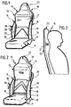
- Figur 1:
- eine schaubildliche Darstellung eines Fahrzeugsitzes mit einer Rückenlehne in unterster Höhenstellung;
- Figur 2:
- eine schaubildliche Darstellung des Fahrzeugsitzes gemäß Figur 1 mit der Rückenlehne in oberster Höhenstellung;
- Figur 3:
- eine schematische Seitenansicht der Rückenlehne mit einer sich abstützenden Person;
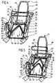
- Figur 4:
- eine schaubildliche Darstellung der Rückenlehne ohne Rückenpolster in unterster Höhenstellung.
- Figur 5:
- eine schaubildliche Darstellung der Rückenlehne ohne Rückenpolster in oberster Höhenstellung;
- Figur 6:
- eine Seitenansicht der Rückenlehne ohne Rückenpolster in unterster Höhenstellung;
- Figur 7:
- eine Seitenansicht der Rückenlehne ohne Rückenpolster in oberster Höhenstellung;
- Figur 8:
- eine Vorderansicht der Rückenlehne ohne Rückenpolster;
- Figur 9:
- eine Schnittansicht längs der Linie 9-9 in Figur 8 in unterster Höhenstellung der Rückenlehne und
- Figur 10:
- eine Schnittansicht längs der Linie 9-9 in Figur 8 in oberster Höhenstellung der Rückenlehne.
- Figure 1:
- a diagrammatic representation of a vehicle seat with a backrest in the lowest height position;
- Figure 2:
- a perspective view of the vehicle seat according to Figure 1 with the backrest in the highest position;
- Figure 3:
- a schematic side view of the backrest with a person supporting himself;
- Figure 4:
- a graphical representation of the backrest without back cushion in the lowest height position.
- Figure 5:
- a graphical representation of the backrest without back cushion in the highest position;
- Figure 6:
- a side view of the backrest without back cushion in the lowest height position;
- Figure 7:
- a side view of the backrest without back cushion in the highest position;
- Figure 8:
- a front view of the backrest without back cushion;
- Figure 9:
- a sectional view taken along the line 9-9 in Figure 8 in the lowest height position of the backrest and
- Figure 10:
- a sectional view taken along line 9-9 in Figure 8 in the uppermost height position of the backrest.
In der Zeichnung ist ein insgesamt mit dem Bezugszeichen 10 belegter
Kraftfahrzeugsitz dargestellt mit einem Sitzteil 11 und einer Rückenlehne
12, die in üblicher Weise mittels einer an sich bekannten und
deshalb in der Zeichnung nur schematisch dargestellten Schwenkmechanik
13 am Sitzteil 11 verschwenkbar gehalten ist.In the drawing there is a
Die Rückenlehne 12 weist zwei Seitenholme 14, 15 auf, die jeweils ein
Seitenpolster 16 tragen, sowie eine insgesamt mit dem Bezugszeichen
18 belegte Rückenstütze, die zwischen den beiden Seitenholmen 14,
15 gehalten ist.The
Die Rückenstütze 18 ist mehrteilig ausgestaltet und umfaßt ein im wesentlichen
in Form eines gleichschenkligen Dreiecks ausgestaltetes
Beckenpolster 19, an dessen beide Schenkel ein Lendenpolster 20 anschließt,
welches wiederum an ein einstückig ausgebildetes Schulter-,
Nacken- und Kopfpolster 21 angrenzt. Wie insbesondere aus Figur 3
deutlich wird, ist insbesondere die Kontur des Schulter-, Nacken- und
Kopfpolsters 21 an die Kontur einer auf dem Kraftfahrzeugsitz 10 Platz
nehmenden Person angepaßt. Die Polsterung der Rückenstütze 18 ist
hierbei derart gewählt, daß im Bereich des Kopfes sowie im hinteren
und unteren Bereich der Rückenstütze ein relativ steifer Polsterwerkstoff,
vorzugsweise Schaumstoff, zum Einsatz kommt, während im
Nacken- und Rückenbereich ein nachgiebigerer Polsterwerkstoff vorgesehen
ist, wobei der Rückenbereich noch nachgiebiger ausgebildet ist
als der Nackenbereich der Rückenstütze. Dadurch wird sichergestellt,
daß im Falle eines Heckaufpralles die sitzende Person aufgrund ihrer
Trägheit die unterschiedlich hart ausgebildeten Polsterwerkstoffe derart
zusammendrückt, daß zum Zeitpunkt des Kopfkontaktes eine vollflächige
Anlage der Person an der Rückenstütze gewährleistet ist, wie
dies in Figur 3 schematisch dargestellt ist.The
In die Rückenstütze 18 ist eine Kopfstütze 23 integriert, so daß der
Kraftfahrzeugsitz 10 als sogenannter Integralsitz ausgebildet ist. Um
die Höhe der Rückenstütze 18, insbesondere die Stellung des Schulter-Nacken-
und Kopfpolsters 21, an die Länge des Oberkörpers der jeweils
Platz nehmenden Person anzupassen, ist die Rückenstütze 18 in
der Höhe kontinuierlich zwischen einer untersten und einer obersten
Höhenstellung verstellbar, indem sowohl das Beckenpolster 19 als auch
das Lendenpolster 20 und das Schulter-, Nacken- und Kopfpolster 21
verschiebbar an den Seitenholmen 14 und 15 gehalten sind. Das Lendenpolster
20 sowie das Schulter-, Nacken- und Kopfpolster 21 können
hierbei in der Höhe um einen größeren Verstellweg verstellt werden als
das Beckenpolster 19, so daß sich zwischen dem Beckenpolster 19 und
dem Lendenpolster 20 ein im wesentlichen V-förmiger Zwischenraum
24 ausbildet, wenn die Rückenstütze 18 eine erhöhte Stellung einnimmt.
Dieser Zwischenraum 24 kann mittels an sich bekannter und
deshalb in der Zeichnung nicht dargestellter Faltenbälge kaschiert werden.
Die V-förmige Ausgestaltung des Zwischenraumes 24 hat sich als
besonders vorteilhaft erwiesen, um sicherzustellen, daß der Zwischenraum
24 von der sitzenden Person praktisch nicht wahrgenommen
wird.In the
Die Stützstruktur und Verstellmechanik der Rückenlehne 12 wird
nachfolgend unter Bezugnahme auf die Figuren 4 bis 10 näher erläutert,
die die Rückenlehne nach Entfernung der Rücken- und Seitenpolster
illustrieren. Wie insbesondere aus den Figuren 4 und 5 deutlich
wird, weisen die beiden Seitenholme 14 und 15 jeweils eine Kulissenplatte
27 bzw. 28 auf mit zwei in Längsrichtung der Seitenholme 14, 15
im Abstand zueinander angeordneten, bogenförmig verlaufenden
Gleitführungen 30 und 31, in denen jeweils ein Kulissenstein 32 bzw.
33 veschiebbar gehalten ist. Die Kulissensteine 32 und 33 sind auf der
der Rückenstütze 18 abgewandten Außenseite der Kulissenplatten 27
bzw. 28 jeweils über eine Zahnstange 34 starr miteinander verbunden.
Letztere kämmt mit einem äußeren Zahnrad 35, das auf der jeweiligen
Außenseite der Kulissenplatten 27 bzw. 28 angeordnet und drehfest an
einer die Kulissenplatte 27 bzw. 28 durchgreifenden Antriebswelle 36
festgelegt ist, die auf der der Rückenstütze 18 zugewandten Innenseite
der jeweiligen Kulissenplatte 27 bzw. 28 ein inneres Zahnrad 37 trägt.
Die drehbar an der Kulissenplatte 27 gehaltene Antriebswelle 36 trägt
auf der Außenseite der Kulissenplatte 27 zusätzlich einen Schwenkhebel
38 mit einem Handgriff 39. Durch Verschwenken des Handgriffes
39 kann die an der Kulissenplatte 27 gehaltene Antriebswelle 36 um
ihre Längsachse 40 verdreht werden.The support structure and adjustment mechanism of the
Zwischen den beiden Kulissenplatten 27 und 28 ist ein Stützrahmen 43
angeordnet mit einem im wesentlichen U-förmigen Kopfbügel 44, dessen
freie Schenkel 45 und 46 an einer Quertraverse 47 festgelegt sind,
deren freie Enden 48 und 49 senkrecht nach vorne abgekröpft und jeweils
an der Innenseite der Kulissenplatte 27 und 28 an einem Kulissenstein
32 unverdrehbar gehalten sind. Der Kopfbügel 44 trägt ungefähr
in Längsrichtung der freien Schenkel 45 und 46 mittig eine verbreiterte
Stütze 50.A
Der Stützrahmen 43 umfaßt außerdem zwei im wesentlichen L-förmig
ausgestaltete Stützbügel 51, 52, deren jeweils längerer Schenkel 53
mit seinem freien Ende an der Quertraverse 47 festgelegt ist und deren
jeweils kürzerer Schenkel 54 mit seinem freien Ende über ein Zwischenstück
55 am Kulissenstein 33 der unteren Gleitführung 31 angelenkt
ist. Der Stützrahmen 43 ist mittels der Kulissensteine 32 und 33
in Längsrichtung verschiebbar und aufgrund der Krümmung der Gleitführungen
30 und 31 zusätzlich um eine quer zur Längsrichtung der
Seitenholme 14 und 15 ausgerichtete Schwenkachse verschwenkbar
33 an den Kulissenplatten 27 und 28 gehalten.The
Unterhalb des Stützrahmens 43 ist zwischen den Kulissenplatten 27
und 28 ein unteres Stützteil 57 angeordnet mit einer schalenförmigen
Beckenschale 58, von der jeweils einer Kulissenplatte 27 bzw. 28 zugewandt
seitliche Haltelaschen 59 und 60 abstehen. An den freien Enden
der Haltelaschen 59 und 60 ist jeweils eine Führungskulisse 61
festgelegt, die in Längsrichtung der Seitenholme 14 und 15 im Abstand
zueinander angeordnete obere und untere Langlöcher 62 bzw. 63 aufweist,
welche jeweils von einem an den Kulissenplatten 27 bzw. 28
festgelegten Führungsbolzen 64 bzw. 65 durchgriffen werden. Mittels
der Langlöcher 62 und 63 und der kooperierenden Führungsbolzen 64
bzw. 65 ist das untere Stützteil 57 in Längsrichtung der Seitenholme
14 und 15 verschiebbar an den Kulissenplatten 27 und 28 gehalten. Below the
In Höhe der oberen und unteren Langlöcher 62 und 63 ist die Führungskulisse
61 als obere bzw. untere Zahnstange 66, 67 ausgestaltet.
Die obere Zahnstange 66 kämmt mit dem inneren Zahnrad 37, das
drehfest auf der Antriebswelle 36 gehalten ist.The guide link is at the height of the upper and lower
In ihrem dem Sitzteil 12 zugewandten unteren Bereich sind die beiden
Kulissenplatten 27 und 28 über eine Querwelle 69 miteinander verbunden,
an deren freien Enden jeweils ein Zahnrad 70 bzw. 71 drehfest
gehalten ist, das mit der unteren Zahnstange 67 der Führungskulisse
61 kämmt.The two are in their lower area facing the
Der Freiraum zwischen der Quertraverse 47 und der Beckenschale 58
wird von einer Lendenschale 73 überdeckt, die mittels Halteringe 74
verschwenkbar an der Quertraverse 47 gehalten ist. Die Lendenschale
73 weist außerdem Stützzapfen 75 auf, die sich in Längsrichtung verschiebbar
am Boden der Beckenschale 58 abstützen.The free space between the
Der Stützrahmen 43 bildet in Kombination mit der Lendenschale 73 ein
oberes Stützteil 77 zur Halterung des Schulter-, Nacken- und Kopfpolsters
21 sowie des Lendenpolsters 20, während die Beckenschale 58
des unteren Stützteiles 57 das Beckenpolster 19 aufnimmt.The
Soll zur Anpassung an eine Platz nehmende Person die Höhe der Rükkenstütze
18 verstellt werden, so wird hierzu der Handgriff 39 um die
Schwenkachse 40 verschwenkt. Dies hat zur Folge, daß über das äußere
Zahnrad 35 die auf der Außenseite der Kulissenplatten 27 und 28
angeordneten Zahnstangen 54 innerhalb der Gleitführungen 30 und 31
verschoben werden, so daß der Stützrahmen 43 des oberen Stützteiles
77 in Längsrichtung der Seitenholme 14 und 15 verschoben und
gleichzeitig aufgrund der Krümmung der Gleitführung 30 und 31 der
Stützrahmen 43 in Richtung auf das Sitzteil 14 nach vorne verschwenkt
wird. Gleichzeitig werden über die inneren Zahnräder 37 und
die oberen Zahnstangen 66 auch die Führungskulissen 61 und damit
das untere Stützteil 57 in Längsrichtung der Stützholme 14 und 15
verschoben. Hierbei wird über die unteren Zahnstangen 67 und die zugeordneten
Zahnräder 70 bzw. 71 in Kombination mit der Querwelle 69
ein Gleichlauf der an den beiden Kulissenplatten 27 und 28 gehaltenen
äußeren und inneren Zahnrädern 35 und 37 sichergestellt. Durch Wahl
des Übersetzungsverhältnisses zwischen den äußeren und inneren
Zahnrädern 35 und 37 wird gewährleistet, daß beim Verschwenken des
Handgriffes 39 das obere Stützteil 77 mit dem daran gehaltenen Kopf-,
Nacken- und Schulterpolster 21 und dem Lendenpolster 20 um den
dreifachen Verstellweg verstellt wird, um den das untere Stützteil 57
mit dem daran festgelegten Beckenpolster 19 verschoben wird.Should be the height of the back support to adapt to a person taking a
Claims (28)
Applications Claiming Priority (2)
| Application Number | Priority Date | Filing Date | Title |
|---|---|---|---|
| DE10111653 | 2001-03-12 | ||
| DE10111653A DE10111653B4 (en) | 2001-03-12 | 2001-03-12 | Backrest for a vehicle seat |
Publications (2)
| Publication Number | Publication Date |
|---|---|
| EP1241047A2 true EP1241047A2 (en) | 2002-09-18 |
| EP1241047A3 EP1241047A3 (en) | 2003-12-17 |
Family
ID=7677049
Family Applications (1)
| Application Number | Title | Priority Date | Filing Date |
|---|---|---|---|
| EP02002655A Withdrawn EP1241047A3 (en) | 2001-03-12 | 2002-02-06 | Backrest for vehicle seats |
Country Status (2)
| Country | Link |
|---|---|
| EP (1) | EP1241047A3 (en) |
| DE (1) | DE10111653B4 (en) |
Cited By (5)
| Publication number | Priority date | Publication date | Assignee | Title |
|---|---|---|---|---|
| EP1400397A2 (en) * | 2002-09-17 | 2004-03-24 | Bertrandt Ingenieurbüro GmbH | Vehicle seat |
| NL1026234C2 (en) * | 2004-05-19 | 2005-11-22 | Savas Seating B V | Chair, particularly for forklift driver, has seat part, vertically directed back rest, two arm rests on opposite sides of seat part and an elbow rest adjustable in height, which partly extends behind the back rest |
| CN103661022A (en) * | 2013-12-10 | 2014-03-26 | 苏州先锋物流装备科技有限公司 | Backrest mechanism |
| WO2021043699A1 (en) * | 2019-09-04 | 2021-03-11 | Brose Fahrzeugteile SE & Co. Kommanditgesellschaft, Coburg | Adjustable neck support |
| CN113194791A (en) * | 2018-12-10 | 2021-07-30 | 德沃康科技集团有限公司 | Lumbar support device for seating furniture and seating furniture having a lumbar support device |
Families Citing this family (3)
| Publication number | Priority date | Publication date | Assignee | Title |
|---|---|---|---|---|
| DE102004030319A1 (en) * | 2004-06-23 | 2006-01-12 | Faurecia Autositze Gmbh & Co. Kg | Headrest assembly for a vehicle seat |
| DE102007018424B4 (en) | 2007-04-17 | 2022-08-04 | Bayerische Motoren Werke Aktiengesellschaft | Vehicle seat with a backrest |
| US11447252B2 (en) * | 2019-10-01 | 2022-09-20 | B/E Aerospace, Inc. | Aircraft seat with separated seat back and seat pan |
Family Cites Families (7)
| Publication number | Priority date | Publication date | Assignee | Title |
|---|---|---|---|---|
| DE2706097A1 (en) * | 1977-01-21 | 1978-07-27 | Rolf Scheel | Car seat construction - has part of seat back vertically adjustable in relation to bottom part of seat using gearing and pivot |
| DE3634500A1 (en) * | 1986-02-10 | 1987-08-20 | Wilfried Prof Dr Me Diebschlag | Seat, in particular car seat |
| DE4238451A1 (en) * | 1992-04-13 | 1993-10-14 | Bayer & Co Gmbh | Vehicle seat with variable contour seat back - has several joints in back support and with length adjustment |
| FR2714340B1 (en) * | 1993-12-28 | 1996-03-01 | Bfa | Improvements to adjustable seat frames and seats fitted with such frames. |
| AU716487B2 (en) * | 1995-09-14 | 2000-02-24 | Autoliv Development Ab | A seat for use in a vehicle |
| US5836647A (en) * | 1997-05-20 | 1998-11-17 | Turman; Ben | Vehicle seat with shock absorption |
| DE19925306C2 (en) * | 1999-06-02 | 2002-11-21 | Faurecia Autositze Gmbh & Co | Backrest of a motor vehicle seat |
-
2001
- 2001-03-12 DE DE10111653A patent/DE10111653B4/en not_active Expired - Fee Related
-
2002
- 2002-02-06 EP EP02002655A patent/EP1241047A3/en not_active Withdrawn
Non-Patent Citations (1)
| Title |
|---|
| None |
Cited By (7)
| Publication number | Priority date | Publication date | Assignee | Title |
|---|---|---|---|---|
| EP1400397A2 (en) * | 2002-09-17 | 2004-03-24 | Bertrandt Ingenieurbüro GmbH | Vehicle seat |
| EP1400397A3 (en) * | 2002-09-17 | 2005-06-29 | Bertrandt Ingenieurbüro GmbH | Vehicle seat |
| NL1026234C2 (en) * | 2004-05-19 | 2005-11-22 | Savas Seating B V | Chair, particularly for forklift driver, has seat part, vertically directed back rest, two arm rests on opposite sides of seat part and an elbow rest adjustable in height, which partly extends behind the back rest |
| CN103661022A (en) * | 2013-12-10 | 2014-03-26 | 苏州先锋物流装备科技有限公司 | Backrest mechanism |
| CN113194791A (en) * | 2018-12-10 | 2021-07-30 | 德沃康科技集团有限公司 | Lumbar support device for seating furniture and seating furniture having a lumbar support device |
| WO2021043699A1 (en) * | 2019-09-04 | 2021-03-11 | Brose Fahrzeugteile SE & Co. Kommanditgesellschaft, Coburg | Adjustable neck support |
| US11807144B2 (en) | 2019-09-04 | 2023-11-07 | Brose Fahrzeugtelle SE & Co. Kommanditgesellschaft, Coburg | Adjustable neck support |
Also Published As
| Publication number | Publication date |
|---|---|
| EP1241047A3 (en) | 2003-12-17 |
| DE10111653B4 (en) | 2006-12-21 |
| DE10111653A1 (en) | 2002-10-02 |
Similar Documents
| Publication | Publication Date | Title |
|---|---|---|
| EP0817731B1 (en) | Adjustable, transversely divided back for a vehicle seat | |
| DE19646470B4 (en) | Motor vehicle seat with a backrest and a seat | |
| DE60210583T2 (en) | VEHICLE SEAT ASSEMBLY WITH A CAM-DRIVEN, SELF-POSITIONING HEADREST | |
| EP0865960B1 (en) | Motor car seat | |
| DE102009021267B4 (en) | Headrest with headrest comfort wings | |
| DE102004017657B4 (en) | Vehicle seat and seat arrangement | |
| DE102006015786B4 (en) | Headrest assembly for a vehicle seat assembly | |
| DE10111653B4 (en) | Backrest for a vehicle seat | |
| EP1449713B1 (en) | Headrest with slidable head supporting element and comfort wings | |
| EP0842814B1 (en) | Headrest for vehicle seats. | |
| DE102018108374A1 (en) | COLLABORABLE LIFTING MECHANISM FOR H-POINT LIFTING | |
| EP2197703A1 (en) | Child protection system for a motor vehicle seat | |
| DE102005022416B4 (en) | Headrest for a vehicle seat | |
| DE102005035947B4 (en) | Flexible backrest for vehicle seat, has flexible plate element of S cross section secured at upper and lower parts to upper and lower ends of backrest frame, and V-hinge between rear of plate element and neck region of backrest frame | |
| WO2000069671A1 (en) | Device for manually and/or automatically adjusting the seat of a motor vehicle comprising several seating elements | |
| DE10243796B4 (en) | vehicle seat | |
| DE102004003389B4 (en) | Headrest on a motor vehicle seat | |
| DE102007028034B4 (en) | Vehicle seat with a swivel shoulder and head area | |
| DE10058518B4 (en) | vehicle seat | |
| DE7728225U1 (en) | PASSENGER CARS WITH A CONTINUOUS OR DIVIDED REAR SEAT BACKREST | |
| DE19914517B4 (en) | Vehicle seat with a seat nose adjustable in position | |
| DE10034441A1 (en) | Automobile seat assembly has a rigid L-shaped frame to hold the seat and backrest frame sections with easy adjustments to position and alignment according to the stature of the occupant | |
| DE10347380B4 (en) | Variable headrest | |
| DE102004014420A1 (en) | Frame and basic construction for car seat, comprising longitudinal gap or recess in seat and backrest | |
| DE102006056081A1 (en) | Vehicle seat for automobile e.g. passenger car, has backrest held at seat frame over multi-joint arrangement and movable relative to seat frame during accident-caused back movement of seat passenger, where seat frame has seat cushion |
Legal Events
| Date | Code | Title | Description |
|---|---|---|---|
| PUAI | Public reference made under article 153(3) epc to a published international application that has entered the european phase |
Free format text: ORIGINAL CODE: 0009012 |
|
| AK | Designated contracting states |
Kind code of ref document: A2 Designated state(s): AT BE CH CY DE DK ES FI FR GB GR IE IT LI LU MC NL PT SE TR |
|
| AX | Request for extension of the european patent |
Free format text: AL;LT;LV;MK;RO;SI |
|
| PUAL | Search report despatched |
Free format text: ORIGINAL CODE: 0009013 |
|
| AK | Designated contracting states |
Kind code of ref document: A3 Designated state(s): AT BE CH CY DE DK ES FI FR GB GR IE IT LI LU MC NL PT SE TR |
|
| AX | Request for extension of the european patent |
Extension state: AL LT LV MK RO SI |
|
| RIC1 | Information provided on ipc code assigned before grant |
Ipc: 7A 47C 7/38 B Ipc: 7A 47C 7/40 B Ipc: 7B 60N 2/64 B Ipc: 7B 60N 2/42 B Ipc: 7B 60N 2/22 B Ipc: 7B 60N 2/68 A |
|
| AKX | Designation fees paid | ||
| REG | Reference to a national code |
Ref country code: DE Ref legal event code: 8566 |
|
| STAA | Information on the status of an ep patent application or granted ep patent |
Free format text: STATUS: THE APPLICATION IS DEEMED TO BE WITHDRAWN |
|
| 18D | Application deemed to be withdrawn |
Effective date: 20040618 |