EP1240969A2 - Welding processes for iron-base ultra fine grained materials and structural components manufactured by the processes - Google Patents
Welding processes for iron-base ultra fine grained materials and structural components manufactured by the processes Download PDFInfo
- Publication number
- EP1240969A2 EP1240969A2 EP02004244A EP02004244A EP1240969A2 EP 1240969 A2 EP1240969 A2 EP 1240969A2 EP 02004244 A EP02004244 A EP 02004244A EP 02004244 A EP02004244 A EP 02004244A EP 1240969 A2 EP1240969 A2 EP 1240969A2
- Authority
- EP
- European Patent Office
- Prior art keywords
- welding
- iron
- range
- average grain
- stainless steel
- Prior art date
- Legal status (The legal status is an assumption and is not a legal conclusion. Google has not performed a legal analysis and makes no representation as to the accuracy of the status listed.)
- Granted
Links
Images


Classifications
-
- B—PERFORMING OPERATIONS; TRANSPORTING
- B23—MACHINE TOOLS; METAL-WORKING NOT OTHERWISE PROVIDED FOR
- B23K—SOLDERING OR UNSOLDERING; WELDING; CLADDING OR PLATING BY SOLDERING OR WELDING; CUTTING BY APPLYING HEAT LOCALLY, e.g. FLAME CUTTING; WORKING BY LASER BEAM
- B23K20/00—Non-electric welding by applying impact or other pressure, with or without the application of heat, e.g. cladding or plating
- B23K20/12—Non-electric welding by applying impact or other pressure, with or without the application of heat, e.g. cladding or plating the heat being generated by friction; Friction welding
-
- C—CHEMISTRY; METALLURGY
- C21—METALLURGY OF IRON
- C21D—MODIFYING THE PHYSICAL STRUCTURE OF FERROUS METALS; GENERAL DEVICES FOR HEAT TREATMENT OF FERROUS OR NON-FERROUS METALS OR ALLOYS; MAKING METAL MALLEABLE, e.g. BY DECARBURISATION OR TEMPERING
- C21D9/00—Heat treatment, e.g. annealing, hardening, quenching or tempering, adapted for particular articles; Furnaces therefor
- C21D9/50—Heat treatment, e.g. annealing, hardening, quenching or tempering, adapted for particular articles; Furnaces therefor for welded joints
-
- B—PERFORMING OPERATIONS; TRANSPORTING
- B23—MACHINE TOOLS; METAL-WORKING NOT OTHERWISE PROVIDED FOR
- B23K—SOLDERING OR UNSOLDERING; WELDING; CLADDING OR PLATING BY SOLDERING OR WELDING; CUTTING BY APPLYING HEAT LOCALLY, e.g. FLAME CUTTING; WORKING BY LASER BEAM
- B23K20/00—Non-electric welding by applying impact or other pressure, with or without the application of heat, e.g. cladding or plating
- B23K20/12—Non-electric welding by applying impact or other pressure, with or without the application of heat, e.g. cladding or plating the heat being generated by friction; Friction welding
- B23K20/122—Non-electric welding by applying impact or other pressure, with or without the application of heat, e.g. cladding or plating the heat being generated by friction; Friction welding using a non-consumable tool, e.g. friction stir welding
- B23K20/1265—Non-butt welded joints, e.g. overlap-joints, T-joints or spot welds
-
- B—PERFORMING OPERATIONS; TRANSPORTING
- B23—MACHINE TOOLS; METAL-WORKING NOT OTHERWISE PROVIDED FOR
- B23K—SOLDERING OR UNSOLDERING; WELDING; CLADDING OR PLATING BY SOLDERING OR WELDING; CUTTING BY APPLYING HEAT LOCALLY, e.g. FLAME CUTTING; WORKING BY LASER BEAM
- B23K20/00—Non-electric welding by applying impact or other pressure, with or without the application of heat, e.g. cladding or plating
- B23K20/12—Non-electric welding by applying impact or other pressure, with or without the application of heat, e.g. cladding or plating the heat being generated by friction; Friction welding
- B23K20/129—Non-electric welding by applying impact or other pressure, with or without the application of heat, e.g. cladding or plating the heat being generated by friction; Friction welding specially adapted for particular articles or workpieces
-
- B—PERFORMING OPERATIONS; TRANSPORTING
- B23—MACHINE TOOLS; METAL-WORKING NOT OTHERWISE PROVIDED FOR
- B23K—SOLDERING OR UNSOLDERING; WELDING; CLADDING OR PLATING BY SOLDERING OR WELDING; CUTTING BY APPLYING HEAT LOCALLY, e.g. FLAME CUTTING; WORKING BY LASER BEAM
- B23K20/00—Non-electric welding by applying impact or other pressure, with or without the application of heat, e.g. cladding or plating
- B23K20/22—Non-electric welding by applying impact or other pressure, with or without the application of heat, e.g. cladding or plating taking account of the properties of the materials to be welded
- B23K20/227—Non-electric welding by applying impact or other pressure, with or without the application of heat, e.g. cladding or plating taking account of the properties of the materials to be welded with ferrous layer
Definitions
- the present invention relates to a nonfusion welding process for iron-base ultra-fine grained materials and particularly to welded structural components with distinguished properties, such as strength, corrosion resistance, etc. inherited from the ultra-fine grained materials.
- the structure of the material at the fused parts is broken up by welding to form a solidification structure, and fine grains in the heat-affected zone grow to coarse grains.
- laser welding JP-A-11-170088
- electron beam welding JP-A-62-64486
- micro-arc welding JP-A-192838
- narrow gap welding JP-A-2000-246438
- JP-A-2000-015462 a welding process, which comprises placing welding pieces together, edge to edge, allowing them to rotate at high speed to effect welding by friction heating
- the temperature of the welding zone is elevated to the melting point so long as welding is carried out by melting, even if laser welding, electron beam welding, micro-arc welding or narrow gap welding is used as a means of low heat input welding, and consequently the ultra-fine structure with controlled grain sizes will be broken up at the welding zone, and thus growth of such ultra-fine crystal grains to coarse grains is inevitable in the heat-affected zone.
- An object of the present invention is to provide a nonfusion welding process for iron-base ultra-fine grained materials having the finest grain sizes among the iron-base materials widely used as structural materials, while keeping their distinguished properties of ultra-fine grained materials as inherited to a maximum, and also to provide structural components manufactured by the process.
- the present invention provides a process for welding iron-base materials, which comprises welding the same or different kinds of iron-base materials, at least one of which is an iron-base ultra-fine grained material free from any amorphous phase and having an average grain size d in a range of 10 nm ⁇ d ⁇ 5 ⁇ 10 3 nm, by friction stir welding.
- the present invention also provides a process for welding iron-base materials, where the iron-base materials are iron-base ultra-fine grained materials free from any amorphous phase, which comprises welding (a) two kinds of the ultra-fine grained materials of chemically and crystallographically same or different kinds, whose average grain sizes d are in a range of 10 nm ⁇ d ⁇ 5 ⁇ 10 3 nm or (b) one kind of the ultra-fine grained material, whose average grain sizes d are in a range of 10 nm ⁇ d ⁇ 5 ⁇ 10 3 nm with another kind or other kinds of the grained materials of chemically and crystallographically same or different kinds, whose average grain sizes d are in a range of 5 ⁇ 10 3 nm d, by friction stir welding.
- the present invention provides a process for welding iron-base materials, where the iron-base materials are austenitic stainless steel, which comprises welding (a) two kinds of the stainless steel from one another, whose average grain sizes d are in a range of 10 nm ⁇ d ⁇ 5 ⁇ 10 3 nm, or (b) one kind of the fine grained stainless steel, whose average grain sizes d are in a range of 10 nm ⁇ d ⁇ 5 ⁇ 10 3 nm, with another kind of the stainless steel, whose average grain sizes d are in a range of 5 ⁇ 10 3 nm ⁇ 3, by friction stir welding.
- the present invention provides a process for welding iron-base materials, where the iron-base materials are ferritic stainless steel with not more than 0.12 wt.% C, free from any of martensite phase and tempered martenite structure, which comprises welding (a) two kinds of the stainless steels, whose average grain sizes d are in a range of 10 nm ⁇ d ⁇ 5 ⁇ 10 3 nm, or (b) one kind of the fine grained steel, whose average grain sizes d are in a range of 10 nm ⁇ d ⁇ 5 ⁇ 10 3 nm, with another kind of the stainless steel, whose average grain sizes d are in a range of 5 ⁇ 10 3 nm ⁇ d, by friction stir welding.
- iron-base materials such as two-phase stainless steel, ultra-fine grained austenitic stainless steel, ferritic stainless steel, etc. can be likewise used for the welding, as will be mentioned later.
- iron-base materials there can be used two-phase stainless steel, fine grained materials of austenitic stainless steel, ferritic stainless steel, two-phase stainless steel, etc. as explained below.
- the present invention provides welding of iron-base fine grained materials, whose major component is iron, crystallographically free from any amorphous phase, where two fine grained materials of chemically and crystallographically same or different kinds, whose average grain sizes d are in the same range as 10 nm ⁇ d ⁇ 5 ⁇ 10 3 nm, are welded to each other by friction stir welding, i.e. a nonfusion welding process.
- friction stir welding i.e. a nonfusion welding process.
- welding of the fine grained materials is effected by friction stir welding.
- the present invention is further characterized by welding one kind of iron-base fine grained material, whose average grain sizes d are in a range of 10 nm ⁇ d ⁇ 5 ⁇ 10 3 nm, with another kind of iron-base fine grained material of chemically and crystallographically same or different kinds, whose d is in a range of 5 ⁇ 10 3 nm ⁇ d, by friction stir welding, i.e. a nonfusion welding process.
- welding of fine grained materials is effected by friction stir welding.
- the present invention concerns particularly welding of austenitic stainless steel, ferritic stainless steel with not more than 0.12 wt.% C, free from any of martensite phase tempered martensite phase, and two-phase stainless steel with both austenite phase and ferrite phase together, characterized by welding two kinds of said steels, whose average grain sizes d are in the same range of 10 nm ⁇ d ⁇ 5 ⁇ 10 3 nm, with one another by friction stir welding, i.e. a nonfusion welding process.
- welding of fine grained materials is effected by friction stir welding.
- the present invention also includes welding of stainless steel of chemically and chrystallographically different kinds in the aforementioned stainless steel.
- the present invention concerns welding of austenitic stainless steel, ferritic stainless steel free from any of martensite phase and tempered martensite phase with not more than 12 wt. % C, and two-phase stainless steel with both austenite phase and ferrite phase together, characterized by welding one kind of fine stainless steel, whose average grain sizes d are in a range of 10 nm ⁇ d ⁇ 5 ⁇ 10 3 nm, with another kind of stainless steel, whose d is in a range of 5 ⁇ 10 3 nm ⁇ d, by friction stir welding.
- welding of fine grained materials is effected by friction stir welding.
- the present invention also includes welding of stainless steel of chemically and crystallographically different kinds in the aforementioned stainless steels.
- the present invention concerns welding of ferritic steels including low-alloy steels, etc. of fine grained materials as non-stainless steels with not more than 7 wt.% Cr and with a ferrite phase base metal, and carbon steel, characterized by welding two kinds of said steel of chemically and crystallographically same or different kinds, whose average grain sizes d are in a range of 10 nm ⁇ d ⁇ 5 ⁇ 10 3 nm, with one another by friction stir welding.
- welding of fine grained materials is effected by friction stir welding.
- the present invention is characterized b welding one kind of the aforementioned steel of fine grained materials, whose average grain sizes d are in a range of 10 nm ⁇ d ⁇ 5 ⁇ 10 3 nm, with another kind of the aforementioned steel, martensitic stainless steel and mild steel of chemically and crystallographically the same or different kinds, whose average grain sizes d are in a range of 5 ⁇ 10 3 nm ⁇ d, by friction stir welding.
- welding of fine grained materials is effected by friction stir welding.
- the present invention is still furthermore characterized by welding one kind of austenitic stainless steel, ferritic stainless steel and two-phase stainless steel consisting of fine grained materials, whose average grain sizes d are in a range of 10 nm ⁇ d ⁇ 5 ⁇ 10 3 nm, with another kind of ferritic steel with not more than 7 wt.% Cr of non-stainless steel of fine grained materials, whose average grain sizes d are likewise in a range of 10 nm ⁇ d ⁇ 5 ⁇ 10 3 nm, and carbon steel by friction stir welding.
- welding of fine grained materials is effected by friction stir welding.
- the present invention is still furthermore characterized by welding one kind of austenitic stainless steel, ferritic stainless steel and two-phase stainless steel of fine grained materials, whose average grain sizes d are in a range of 10 nm ⁇ d ⁇ 5 ⁇ 10 3 nm with another kind of ferritic steel with not more than 7 wt.% Cr of non-stainless steel grained materials, whose average grain sizes d are in a range of 5 ⁇ 10 3 nm ⁇ d, and carbon steel, and furthermore martensitic stainless steel and mild steel by friction stir welding.
- welding of fine grained materials is effected by friction stir welding.
- the present invention is still furthermore characterized by welding one kind of ferritic stainless steel with not more than 7 wt.% Cr, of non-stainless steel grained materials, whose average grain sizes d are in a range of 10 nm ⁇ d ⁇ 5 ⁇ 10 3 nm, and carbon steel and another kind of austenitic stainless steel, ferritic stainless steel and two-phase stainless steel, whose average grain sizes d are in a range of 5 ⁇ 10 3 nm ⁇ d, by friction stir welding.
- welding of fine grained materials is effected by friction stir welding.
- the present invention concerns structural components made by friction stir welding of ferritic steel with not more than 7 wt.% Cr, carbon steel, where the zones including friction stir welding zone are annealed in a range of 600° to 850°C.
- friction stir welding of iron-base fine grained materials is carried out in a coolant selected from water, oil and inert gases, or while spraying the coolant in the vicinity or over the whole of the welding zone.
- the friction stir welding is a method which comprises pressing a high speed-rotating bar (tool) of a heat-resistant, hard-to-react material to parts of metallic pieces to be welded on both sides, thereby readily elevating the temperature of the parts to higher temperature of not more than the melting point due to the generated heat of friction and giving rise to plastic flow of the parts of the metallic pieces to be welded to effect stir welding of the parts on both sides.
- Friction stir welding of iron-base materials can be carried out by use of a tool with a resistance high enough to withstand elevated temperatures due to heat generation between the tool and pieces to be friction stir welded when the high speed rotating tool is pressed into the pieces and also by the resulting plastic flow and stirring and also by use of an apparatus with a rigidity high enough to withstand upward pressures developed from within the stirring zone.
- friction stir zone temperature is not more than the melting point.
- Al alloy for reference [ Masatoshi Enomoto: Light Metal Welding 36 (1998), 25 or Hisanobu Okamura, Kinya Aota and Masakuni Ekado: Light Metal 50 (2,000), 166-172], it corresponds to 2/3 of the melting point in terms of Celsius temperature grades. That is, the melting point is 1,500°C and thus the friction stir zone temperature of the neighboring iron-base materials would be about 1,000°C.
- the structure of the friction stir zone i.e. grain sizes, would grow more than the fine grains of the base metal would do, but the material structure formed after the melting in case of welding is not a solidification structure resulting in no solidification shrinkage.
- the heat-affected zone of the part in the close vicinity of the friction stir zone receives less heat hysteresis of temperature-time, so that the grains will not grow so much.
- the present invention can have such advantages as less quality change and less deformation of the materials after the welding than those in case of the conventional welding processes.
- Grain growth of ultra-fine grains is suppressed by pinning of dispersed fine particles of the compound, etc. That is, in the iron-base materials of fine grains made by forming structurally dispersed fine particles of the materials, superplasticity can be also utilized in the plastic deformation at elevated temperatures, which is so called “stirring", and the effect of grain boundary pinning of the existing ultra-fine dispersed particles is also added thereto to make higher the effect of suppression of grain growth during the welding.
- the best effect can be obtained with austenic stainless steel, ferritic stainless steel and two-phase stainless steel with an austenite phase and a ferrite phase together, all of whose average grain sizes d are 10 nm ⁇ d ⁇ 5 ⁇ 10 3 nm, or with fine grained materials such as ferritic steel with a ferrite phase base metal as non-stainless steel and carbon steel, where fine ferrite phase grains of non-stainless steel designate neither ordinary hardened structure nor tempered structure, but a sintered structure of highly processed powder or a structure of highly rolled, processed and heat-treated plate materials, though similar to each other in composition, which comprises ultra-fine grains of carbide, etc. as precipitated in the ferrite phase.
- Table 1 shows chemical composition of plate test pieces subjected to tests of the present friction stir welding, i.e. butt welding, where austenic stainless steel (Nos. 1, 2, 3 and 4), ferritic stainless steel (Nos. 5 and 6), two-phase stainless steel (No. 7), ferritic steel (No. 8) and carbon steel (No. 9) with a ferrite phase base metal as non-stainless steel, which are typical of fine grained materials, and typical materials (Nos. 10-16) having ordinary grain sizes (not less than 5 ⁇ m), which are chemically, crystallographically and structurally closest to the aforementioned materials, are given.
- Test pieces Nos. 17 and 18 are also shown in Table 1 as counterpart members to be welded to the fine grained materials.
- Table 1 also shows average grain sizes, and tensile strength and plastic elongation of the test pieces as strength data.
- Measurement of grain sizes was carried out on the TEM-observed dark-field images for materials having average grain sizes of not more than 2 ⁇ m and on SEM-observed images for those having average grain sizes of more than 2 ⁇ m.
- Test pieces Nos. 15 and 17 had a hardened and tempered structure, where old austenite grain sizes are shown as grain sizes.
- Fig. 1 shows a picture of TEM structure of test pieces, where the average grain size was 250 nm.
- gas-atomized powder was prepared on the basis of compositions of Table 1, and processed by mechanical milling (MM) in a high energy ball mill made from stainless steel (SUS 304), using SUS 304 stainless steel balls to obtain highly processed powder.
- the processed powder weighed about 1 kg.
- MM-processed powder was subjected to vacuum canning into a mild steel can and processed by hot isostatic pressing (NIP) under isostatic pressure of 196 MPa using an inert gas as a medium.
- NIP hot isostatic pressing
- the HIP-processed materials were ultimately processed to a dimension of 3 ⁇ 50 ⁇ 200 mm 2 through a hot forging treatment. Details of processes for manufacturing fine grained materials and reference materials corresponding to the materials of Table 1 are summarized in Table 2.
- the powder is brought into a ultra-fined ferrite phase by utilizing highly processing-induced martensite transformation, and then subjected to solidification and heat processing treatment to occasion back-transformation to bring the bulk material into a fine grained austenite phase.
- the austenite phase of the two phases is made into ultra-fine grains through the same processes as above.
- Test pieces Nos. 5, 6 and 7 consisting of ferrite phase structure in part and Nos. 8 and 9 consisting of ferrite phase on the whole are adjusted by causing recrystallization in the course of solidification and heat processing step of highly processed powder, where grain growth is suppressed by precipitation of ultrafine grains of TiC or carbides of metal components in the materials, thereby producing ultra-fine grains.
- Test piece No. 8 is manufactured through the hot processing step by temperature elevation from a lower temperature, i.e. according to a process for producing ultra-fine grains without martensitic transformation, whereas the structure of test piece No. 15 of Table 1 is formed through the ordinary hardening and tempering.
- the high processing step is carried out by rolling.
- Butt welding was carried out according to welding combinations shown in Table 3, were, for example, a welding combination of No. 1 with No. 10 of Table 1 is given by "1 - 10".
- Fig. 2 is a schematic perspective view showing a method for carrying out the friction stir welding.
- Test pieces 1 and 2 in combination is placed on an iron surface plate (not shown in the drawing), abutted edge by edge, and then fixed by securing jigs 3.
- High speed-rotating tungsten bar tool 4 is inserted into a weld part and moved along weld line 5 to conduct friction stir welding.
- Weld bead 6 is formed after the welding, and a plastic flow zone, a plastic deformation zone and a heat-affected zone are formed from the center of weld cross-section 7 towards the base metal.
- Said tungsten tool 4 has a convex tip end, and on M screw is threaded at the small-diameter part (pin) at the remotest part of the tip end.
- the dimension of the small-diameter shoulder part is 5 mm in diameter and about 3 mm long. Large-diameter part is 10 mm in diameter. The small-diameter part is kept as inserted into the material until the shoulder part comes in contact with the pieces to be welded.
- Rotation speed is set to 1,300 rpm and the moving speed is set to 150 mm/min.
- the rotation speed and the moving speed are variable, but in this Example, they were set as given above.
- Welding temperature was measured at welding of test pieces Nos. 1, 5, 8 and 18 by embedding a thermocouple into the abutted pieces at the back side.
- Temperature just on the back side of welding bead was in a range of 950° to 1,150°C in all the cases, which was corresponded to about 2/3 of the melting points as in the case of the aforementioned Al alloy.
- Downward load was measured at the welding by a load cell provided at the back side of the test pieces-fixed surface plate, and it was found that the pressure on the tool at the welding was 25 to 65 MPa.
- Fig. 3 shows a picture of 1-1 joint appearance as a typical example
- Fig. 5 shows a picture of cross-section thereof at the joint. It is apparent from these pictures that welding was effected without any welding failure.
- Weld bead width was substantially identical with tool shoulder diameter, and it was found from the cross-sectional shape that the abutted edges of 1-1 joint were welded down to the back side as if the abutted edge zones were completely stirred. In all the butt welding tests as given in Table 3, similar results were obtained. Structurally, the grain sizes in the stirred zone of 1-1 joint was 440 nm and thus the grains were not so coarsened. That is, it can be concluded that the friction stir welding is a welding process capable of sufficiently maintaining a fine grained structure.
- Table 3 summaries features of evaluation results of butt welding tests according to this Example. Evaluation of grain sizes in the stirred zone was made on the basis of average grain sizes d of fine grains:
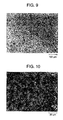
- Fig. 9 shows a structure at boundary between the joint of 8-18 and No. 18 base material. As shown in Fig. 10, a martensitic structure is formed. In such structures, the strength characteristics were found unsatisfactory, and the tensile tests revealed that the readily deformable base metal took part in deformation.
- Example 1 Weldability of fine grained materials can be basically well evaluated by the butt welding of Example 1.
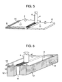
- This Example shows various welding processes to be utilized for the welded structural components, where embodiments of lap welding as shown in Fig. 5 will be described. Though the lap welding differs from butt welding, combinations of 1-1, 1-10 and -12 of Table 3 were used as typical examples.
- Overlapping width was 15 mm.
- Tungsten tool 4 12 mm in shoulder diameter, 6 mm in pin diameter, and 5 mm in pin length, was used for welding at a rotation speed of 1,500 rpm and a moving speed of 150 mm/min.
- Welding depth was 5 mm-odd, where the lower plate material 8 was stir welded down to 2 mm-odd.
- Iron support materials 12 were arranged to pinch one upright plate material 11, and another plate material 13 was placed thereon so that the center line of plate material 13 could be located on said upright plate material 11.
- the plate materials each were fixed by press jigs 3 and 14.
- Tip end dimensions of tungsten tool 4 were the same as in Example 2. Welding was carried out at a rotation speed of 1,500 rpm and a moving speed of 150 mm/min. Welding state was the same as in Example 2.
- Plate material of No. 1, 3, 5 or 7, in dimensions of 3 ⁇ 100 ⁇ 200 m 3 was deformed by bending to form cylindrical material 15, and then iron support plate 16 was abutted thereto along a line just under the butt line, i.e. weld line 5. Then, side edges of cylindrical material 15 were subjected to tack welding 17 by spot welding or friction stir welding so that the side edges may not be departed from each other.
- Tungsten tool 4 had such tip end dimensions as 8 mm in shoulder diameter, 4 mm in pin diameter and less than 2 mm in length. Welding was carried out at a rotation speed of 1,700 rpm and a moving speed of 130 mm/min.
- Pipes were each 150 mm long.
- Disc-shaped support material 19 having a diameter sufficiently close to the pipe inner diameter was inserted into pipe material 18 to a depth of nearly one-half of the disc thickness, whereas other half of the disc was inserted into another pipe 20.
- Tack welding was carried out at 4 diagonally located points to prevent the abutted edges (weld line 5) from departing from each other as in Example 4.
- Both outer ends of pipes were fixed by press jigs 3, and then tool 4 was inserted into weld line 5.
- Tool 4 was rotated at a rotation speed of 1,700 rpm, but not moved, whereas the entirely of the pipes was rotated at the center of the pipes to weld both pipes at a weld moving speed of 130 mm/min.
- Friction stir welding can be fully applied to welding of structural components based on combinations with fine grained materials.
- joints between fine grained materials themselves or between fine grained materials and grained materials having grain sizes of not less than 5 ⁇ m can be obtained without impairing distinguished strength and corrosion resistance of ultra-fine grained materials, or structural components including straight or curved joints can be manufactured.
- the structural components including the aforementioned joints show distinguished characteristics, e.g. strength, corrosion resistance, etc. of ultra-fine grained materials.
Abstract
Description
- The present invention relates to a nonfusion welding process for iron-base ultra-fine grained materials and particularly to welded structural components with distinguished properties, such as strength, corrosion resistance, etc. inherited from the ultra-fine grained materials.
- In conventional welding processes for assembling structural components of metallic materials, a welding process for melting parts of a material placed together, edge by edge, is popular.
- The structure of the material at the fused parts is broken up by welding to form a solidification structure, and fine grains in the heat-affected zone grow to coarse grains. To suppress such a grain growth to coarse grains in the heat-affected zone as strongly as possible, laser welding (JP-A-11-170088), electron beam welding (JP-A-62-64486), micro-arc welding (JP-A-192838), narrow gap welding (JP-A-2000-246438), etc., all of which can reduce the welding heat input to a base metal, have been proposed.
- Furthermore, a welding process, which comprises placing welding pieces together, edge to edge, allowing them to rotate at high speed to effect welding by friction heating (JP-A-2000-015462) has been proposed.
- As welding processes without melting of the base metal, on the other hand, solding and brazing processes based on melting of a low melting point filler are now available.
- To obtain desirable properties of materials such as strength, corrosion resistance, etc., processes for making crystal grains ultra-fine have been also recently proposed. For example, many iron-base ultra-fine materials having grain sizes of not more than 5 µm are now under development [e.g. The second Symposium on Super Metal (1999): by The Japan Research and Development Center for Metals (a foundational judicial person), etc. and The Fourth Workshop on Ultra-Steel (2000) by National Research Institute for Materials, belonging to Science and Technology Agency, Japan].
- When structural components are assembled through joints formed not by soldering and blazing, but by melting of ultra-fine grained materials, the temperature of the welding zone is elevated to the melting point so long as welding is carried out by melting, even if laser welding, electron beam welding, micro-arc welding or narrow gap welding is used as a means of low heat input welding, and consequently the ultra-fine structure with controlled grain sizes will be broken up at the welding zone, and thus growth of such ultra-fine crystal grains to coarse grains is inevitable in the heat-affected zone.
- Deformation of welding joints is inevitable in the course of solidification and cooling after the melting. Butt friction welding is not suitable for assembling welded structural components including ordinary plate materials.
- An object of the present invention is to provide a nonfusion welding process for iron-base ultra-fine grained materials having the finest grain sizes among the iron-base materials widely used as structural materials, while keeping their distinguished properties of ultra-fine grained materials as inherited to a maximum, and also to provide structural components manufactured by the process.
- The present invention provides a process for welding iron-base materials, which comprises welding the same or different kinds of iron-base materials, at least one of which is an iron-base ultra-fine grained material free from any amorphous phase and having an average grain size d in a range of 10 nm < d ≤ 5 × 10³ nm, by friction stir welding.
- The present invention also provides a process for welding iron-base materials, where the iron-base materials are iron-base ultra-fine grained materials free from any amorphous phase, which comprises welding (a) two kinds of the ultra-fine grained materials of chemically and crystallographically same or different kinds, whose average grain sizes d are in a range of 10 nm < d ≤ 5 × 10³ nm or (b) one kind of the ultra-fine grained material, whose average grain sizes d are in a range of 10 nm < d ≤ 5 × 10³ nm with another kind or other kinds of the grained materials of chemically and crystallographically same or different kinds, whose average grain sizes d are in a range of 5 × 10³ nm d, by friction stir welding.
- Furthermore, the present invention provides a process for welding iron-base materials, where the iron-base materials are austenitic stainless steel, which comprises welding (a) two kinds of the stainless steel from one another, whose average grain sizes d are in a range of 10 nm < d ≤ 5 × 10³ nm, or (b) one kind of the fine grained stainless steel, whose average grain sizes d are in a range of 10 nm < d ≤ 5 × 10³ nm, with another kind of the stainless steel, whose average grain sizes d are in a range of 5 × 10³ nm < 3, by friction stir welding.
- Still furthermore, the present invention provides a process for welding iron-base materials, where the iron-base materials are ferritic stainless steel with not more than 0.12 wt.% C, free from any of martensite phase and tempered martenite structure, which comprises welding (a) two kinds of the stainless steels, whose average grain sizes d are in a range of 10 nm < d ≤ 5 × 10³ nm, or (b) one kind of the fine grained steel, whose average grain sizes d are in a range of 10 nm < d ≤ 5 × 10³ nm, with another kind of the stainless steel, whose average grain sizes d are in a range of 5 × 10³ nm < d, by friction stir welding.
- In the present invention, other iron-base materials such as two-phase stainless steel, ultra-fine grained austenitic stainless steel, ferritic stainless steel, etc. can be likewise used for the welding, as will be mentioned later.
- In the present invention, as the iron-base materials there can be used two-phase stainless steel, fine grained materials of austenitic stainless steel, ferritic stainless steel, two-phase stainless steel, etc. as explained below.
- Other objects, features and advantages of the invention will become apparent from the following description of the embodiments of the invention taken in conjunction with the accompanying drawings.
-
- Fig. 1 is a TEM structural picture of ultra-fine grained stainless steel (SUS 304).
- Fig. 2 is a schematic perspective view of butt friction stir welding.
- Fig. 3 is a picture of friction stir welding zone of ultra-fine grained stainless steel (SUS 304).
- Fig. 4 is a picture of the cross-section of friction stir welding zone of Fig. 3.
- Fig. 5 is a schematic perspective view of lap friction stir welding.
- Fig. 6 is a schematic perspective view of T-type friction stir welding.
- Fig. 7 is a schematic perspective view of fabrication of a pipe by friction stir welding.
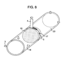
- Fig. 8 is a schematic perspective view of friction stir welding of pipes.
- Fig. 9 is an optical micrograph showing structure of boundary between a joint subjected to martensitic transformation and a base material.
- Fig. 10 is an optical micrograph showing structure of a joint subjected to martensitic transformation.
-
- To attain the aforementioned object, the present invention provides welding of iron-base fine grained materials, whose major component is iron, crystallographically free from any amorphous phase, where two fine grained materials of chemically and crystallographically same or different kinds, whose average grain sizes d are in the same range as 10 nm < d ≤ 5 × 10³ nm, are welded to each other by friction stir welding, i.e. a nonfusion welding process. In manufacturing welded structural components from the fine grained materials, welding of the fine grained materials is effected by friction stir welding.
- The present invention is further characterized by welding one kind of iron-base fine grained material, whose average grain sizes d are in a range of 10 nm < d ≤ 5 × 10³ nm, with another kind of iron-base fine grained material of chemically and crystallographically same or different kinds, whose d is in a range of 5 × 10³ nm < d, by friction stir welding, i.e. a nonfusion welding process. In manufacturing welded structure components from the fine grained materials, welding of fine grained materials is effected by friction stir welding.
- The present invention concerns particularly welding of austenitic stainless steel, ferritic stainless steel with not more than 0.12 wt.% C, free from any of martensite phase tempered martensite phase, and two-phase stainless steel with both austenite phase and ferrite phase together, characterized by welding two kinds of said steels, whose average grain sizes d are in the same range of 10 nm < d ≤ 5 × 10³ nm, with one another by friction stir welding, i.e. a nonfusion welding process. In manufacturing welded structural components from the fine grained materials, welding of fine grained materials is effected by friction stir welding. The present invention also includes welding of stainless steel of chemically and chrystallographically different kinds in the aforementioned stainless steel.
- Still furthermore, the present invention concerns welding of austenitic stainless steel, ferritic stainless steel free from any of martensite phase and tempered martensite phase with not more than 12 wt. % C, and two-phase stainless steel with both austenite phase and ferrite phase together, characterized by welding one kind of fine stainless steel, whose average grain sizes d are in a range of 10 nm < d ≤ 5 × 10³ nm, with another kind of stainless steel, whose d is in a range of 5 × 10³ nm < d, by friction stir welding. In manufacturing welded structural components from the fine grained materials, welding of fine grained materials is effected by friction stir welding. The present invention also includes welding of stainless steel of chemically and crystallographically different kinds in the aforementioned stainless steels.
- Still furthermore, the present invention concerns welding of ferritic steels including low-alloy steels, etc. of fine grained materials as non-stainless steels with not more than 7 wt.% Cr and with a ferrite phase base metal, and carbon steel, characterized by welding two kinds of said steel of chemically and crystallographically same or different kinds, whose average grain sizes d are in a range of 10 nm < d ≤ 5 × 10³ nm, with one another by friction stir welding. In manufacturing welded structural components from the fine grained materials, welding of fine grained materials is effected by friction stir welding.
- In the ferritic steels including low-alloy steels, etc. as non-stainless steels with not more than 7 wt.% Cr and with a ferrite phase base metal and carbon steel, the present invention is characterized b welding one kind of the aforementioned steel of fine grained materials, whose average grain sizes d are in a range of 10 nm < d ≤ 5 × 10³ nm, with another kind of the aforementioned steel, martensitic stainless steel and mild steel of chemically and crystallographically the same or different kinds, whose average grain sizes d are in a range of 5 × 10³ nm < d, by friction stir welding. In manufacturing welded structural components from the ultra-fine grained materials, welding of fine grained materials is effected by friction stir welding.
- The present invention is still furthermore characterized by welding one kind of austenitic stainless steel, ferritic stainless steel and two-phase stainless steel consisting of fine grained materials, whose average grain sizes d are in a range of 10 nm < d ≤ 5 × 10³ nm, with another kind of ferritic steel with not more than 7 wt.% Cr of non-stainless steel of fine grained materials, whose average grain sizes d are likewise in a range of 10 nm < d ≤ 5 × 10³ nm, and carbon steel by friction stir welding. In manufacturing welded structural components from the fine grained materials, welding of fine grained materials is effected by friction stir welding.
- The present invention is still furthermore
characterized by welding one kind of austenitic stainless steel, ferritic stainless steel and two-phase stainless steel of fine grained materials, whose average grain sizes d are in a range of 10 nm < d ≤ 5 × 10³ nm with another kind of ferritic steel with not more than 7 wt.% Cr of non-stainless steel grained materials, whose average grain sizes d are in a range of 5 × 10³ nm < d, and carbon steel, and furthermore martensitic stainless steel and mild steel by friction stir welding. In manufacturing welded structural components from the fine grained materials, welding of fine grained materials is effected by friction stir welding. - The present invention is still furthermore characterized by welding one kind of ferritic stainless steel with not more than 7 wt.% Cr, of non-stainless steel grained materials, whose average grain sizes d are in a range of 10 nm < d ≤ 5 × 10³ nm, and carbon steel and another kind of austenitic stainless steel, ferritic stainless steel and two-phase stainless steel, whose average grain sizes d are in a range of 5 × 10³ nm < d, by friction stir welding. In manufacturing welded structural components from the fine grained materials, welding of fine grained materials is effected by friction stir welding.
- The present invention concerns structural components made by friction stir welding of ferritic steel with not more than 7 wt.% Cr, carbon steel, where the zones including friction stir welding zone are annealed in a range of 600° to 850°C.
- In the present invention, friction stir welding of iron-base fine grained materials is carried out in a coolant selected from water, oil and inert gases, or while spraying the coolant in the vicinity or over the whole of the welding zone.
- The friction stir welding is a method which comprises pressing a high speed-rotating bar (tool) of a heat-resistant, hard-to-react material to parts of metallic pieces to be welded on both sides, thereby readily elevating the temperature of the parts to higher temperature of not more than the melting point due to the generated heat of friction and giving rise to plastic flow of the parts of the metallic pieces to be welded to effect stir welding of the parts on both sides.
- By moving the tool along the weld line, welded structural components including straight welding and curved welding can be obtained.
- In the conventional butt friction welding, it is hard to obtain straight welding and curved welding. Due to the innovation of various material structure control processes ultra-fine grains having average grain sizes of not more than 5 µm or even not more than 100 nm have been produced in case of iron-base materials [e.g. The second Symposium on Super Metal (1999) by The Japan Research and Development Center for Metals (a foundation judicial person) Japan, etc. and The fourth Workshop on Ultra-Steel (2000) by National Research Institute for Materials, belonging to Science and Technology Agency, Japan].
- However, such distinguished properties of materials with the fine grains as strength, corrosion resistance, etc. have not been utilized in the welded structural components because such an fine grained structure cannot be maintained throughout the conventional welding processes, and thus have been limited to uses as non-weldable structural components.
- Attempts to deal with the conventional welding processes by low heat input welding, particularly by narrow welding have been already made [e.g. The fourth Workshop on Ultra-Steel (2000), by National Research Institute for Materials, belonging to Science and Technology Agency, Japan], but structure breaking-up at joints and coarsening of crystal grains in the heat-affected zones are inevitable.
- Friction stir welding of iron-base materials can be carried out by use of a tool with a resistance high enough to withstand elevated temperatures due to heat generation between the tool and pieces to be friction stir welded when the high speed rotating tool is pressed into the pieces and also by the resulting plastic flow and stirring and also by use of an apparatus with a rigidity high enough to withstand upward pressures developed from within the stirring zone.
- Generally, friction stir zone temperature is not more than the melting point. In case of Al alloy for reference [ Masatoshi Enomoto: Light Metal Welding 36 (1998), 25 or Hisanobu Okamura, Kinya Aota and Masakuni Ekado: Light Metal 50 (2,000), 166-172], it corresponds to 2/3 of the melting point in terms of Celsius temperature grades. That is, the melting point is 1,500°C and thus the friction stir zone temperature of the neighboring iron-base materials would be about 1,000°C.
- At the friction stir zone temperature, the structure of the friction stir zone, i.e. grain sizes, would grow more than the fine grains of the base metal would do, but the material structure formed after the melting in case of welding is not a solidification structure resulting in no solidification shrinkage.
- Also the heat-affected zone of the part in the close vicinity of the friction stir zone receives less heat hysteresis of temperature-time, so that the grains will not grow so much.
- Due to these effects, the present invention can have such advantages as less quality change and less deformation of the materials after the welding than those in case of the conventional welding processes.
- Grain growth of ultra-fine grains is suppressed by pinning of dispersed fine particles of the compound, etc. That is, in the iron-base materials of fine grains made by forming structurally dispersed fine particles of the materials, superplasticity can be also utilized in the plastic deformation at elevated temperatures, which is so called "stirring", and the effect of grain boundary pinning of the existing ultra-fine dispersed particles is also added thereto to make higher the effect of suppression of grain growth during the welding.
- Thus, in the friction stir welding, the best effect can be obtained with austenic stainless steel, ferritic stainless steel and two-phase stainless steel with an austenite phase and a ferrite phase together, all of whose average grain sizes d are 10 nm < d ≤ 5 × 10³ nm, or with fine grained materials such as ferritic steel with a ferrite phase base metal as non-stainless steel and carbon steel, where fine ferrite phase grains of non-stainless steel designate neither ordinary hardened structure nor tempered structure, but a sintered structure of highly processed powder or a structure of highly rolled, processed and heat-treated plate materials, though similar to each other in composition, which comprises ultra-fine grains of carbide, etc. as precipitated in the ferrite phase.
- However, when the welding temperature falls within the hardening temperature range in the friction stir welding of the non-stainless steel materials, there is a fear that a hardening effect occurs, even if the counterpart is a stainless steel joint. Thus, a good joint can be obtained by carrying out heat treatment to temper the parts including the joint.
- When parts or the whole of welded structural components are made from the aforementioned fine grained materials, features of the aforementioned friction stir welding can be incorporated into the structural components.
- To thoroughly maintain the distinguished properties of fine grained materials and much more reduce the residual stress in the welded structural components and the deformation of the structural component, it is more effective to cool the joints, during the welding, with any of such coolants as water, oil and an inert gas capable of accelerating the cooling speed around the joints.
- The present invention will be described in detail below, referring to Examples and Drawings.
- Table 1 shows chemical composition of plate test pieces subjected to tests of the present friction stir welding, i.e. butt welding, where austenic stainless steel (Nos. 1, 2, 3 and 4), ferritic stainless steel (Nos. 5 and 6), two-phase stainless steel (No. 7), ferritic steel (No. 8) and carbon steel (No. 9) with a ferrite phase base metal as non-stainless steel, which are typical of fine grained materials, and typical materials (Nos. 10-16) having ordinary grain sizes (not less than 5 µm), which are chemically, crystallographically and structurally closest to the aforementioned materials, are given.
- Test pieces Nos. 17 and 18 are also shown in Table 1 as counterpart members to be welded to the fine grained materials.
- Table 1 also shows average grain sizes, and tensile strength and plastic elongation of the test pieces as strength data.
- Measurement of grain sizes was carried out on the TEM-observed dark-field images for materials having average grain sizes of not more than 2 µm and on SEM-observed images for those having average grain sizes of more than 2 µm. Test pieces Nos. 15 and 17 had a hardened and tempered structure, where old austenite grain sizes are shown as grain sizes.

- Fig. 1 shows a picture of TEM structure of test pieces, where the average grain size was 250 nm.
- In test pieces Nos. 1, 25, 6 and 7, Ti and C were added to precipitate TiC.
- Plate materials shown in Table 1 were prepared as follows:
- For test pieces Nos. 1, 2, 5, 6, 7, 8 and 9, gas-atomized powder was prepared on the basis of compositions of Table 1, and processed by mechanical milling (MM) in a high energy ball mill made from stainless steel (SUS 304), using SUS 304 stainless steel balls to obtain highly processed powder. The processed powder weighed about 1 kg.
- MM-processed powder was subjected to vacuum canning into a mild steel can and processed by hot isostatic pressing (NIP) under isostatic pressure of 196 MPa using an inert gas as a medium. The HIP-processed materials were ultimately processed to a dimension of 3 × 50 × 200 mm2 through a hot forging treatment. Details of processes for manufacturing fine grained materials and reference materials corresponding to the materials of Table 1 are summarized in Table 2.


- As to austenitic stainless steel Nos. 1 and 2, the powder is brought into a ultra-fined ferrite phase by utilizing highly processing-induced martensite transformation, and then subjected to solidification and heat processing treatment to occasion back-transformation to bring the bulk material into a fine grained austenite phase.
- As to two-phase stainless steel No. 7, the austenite phase of the two phases is made into ultra-fine grains through the same processes as above.
- Test pieces Nos. 5, 6 and 7 consisting of ferrite phase structure in part and Nos. 8 and 9 consisting of ferrite phase on the whole are adjusted by causing recrystallization in the course of solidification and heat processing step of highly processed powder, where grain growth is suppressed by precipitation of ultrafine grains of TiC or carbides of metal components in the materials, thereby producing ultra-fine grains.
- Test piece No. 8 is manufactured through the hot processing step by temperature elevation from a lower temperature, i.e. according to a process for producing ultra-fine grains without martensitic transformation, whereas the structure of test piece No. 15 of Table 1 is formed through the ordinary hardening and tempering. For test pieces Nos. 3 and 4, the high processing step is carried out by rolling.
- Butt welding was carried out according to welding combinations shown in Table 3, were, for example, a welding combination of No. 1 with No. 10 of Table 1 is given by "1 - 10".
- Butt welding of all test pieces of Table 1 was not carried out, but the welding combinations shown in Table 3 were judged satisfactory for examples of butt welding of ultra-fine grained materials themselves, fine grain materials with different kinds of ordinary reference materials and austenitic stainless steel, ferritic stainless steel, two-phase stainless steel, ferritic steel and carbon steel according to the present invention.
- Fig. 2 is a schematic perspective view showing a method for carrying out the friction stir welding.
Test pieces 1 and 2 in combination is placed on an iron surface plate (not shown in the drawing), abutted edge by edge, and then fixed by securingjigs 3. High speed-rotatingtungsten bar tool 4 is inserted into a weld part and moved alongweld line 5 to conduct friction stir welding. -
Weld bead 6 is formed after the welding, and a plastic flow zone, a plastic deformation zone and a heat-affected zone are formed from the center ofweld cross-section 7 towards the base metal. Saidtungsten tool 4 has a convex tip end, and on M screw is threaded at the small-diameter part (pin) at the remotest part of the tip end. The dimension of the small-diameter shoulder part is 5 mm in diameter and about 3 mm long. Large-diameter part is 10 mm in diameter. The small-diameter part is kept as inserted into the material until the shoulder part comes in contact with the pieces to be welded. Rotation speed is set to 1,300 rpm and the moving speed is set to 150 mm/min. The rotation speed and the moving speed are variable, but in this Example, they were set as given above. Welding temperature was measured at welding of test pieces Nos. 1, 5, 8 and 18 by embedding a thermocouple into the abutted pieces at the back side. - Temperature just on the back side of welding bead was in a range of 950° to 1,150°C in all the cases, which was corresponded to about 2/3 of the melting points as in the case of the aforementioned Al alloy. Downward load was measured at the welding by a load cell provided at the back side of the test pieces-fixed surface plate, and it was found that the pressure on the tool at the welding was 25 to 65 MPa.
- Fig. 3 shows a picture of 1-1 joint appearance as a typical example, and Fig. 5 shows a picture of cross-section thereof at the joint. It is apparent from these pictures that welding was effected without any welding failure.
- Weld bead width was substantially identical with tool shoulder diameter, and it was found from the cross-sectional shape that the abutted edges of 1-1 joint were welded down to the back side as if the abutted edge zones were completely stirred. In all the butt welding tests as given in Table 3, similar results were obtained. Structurally, the grain sizes in the stirred zone of 1-1 joint was 440 nm and thus the grains were not so coarsened. That is, it can be concluded that the friction stir welding is a welding process capable of sufficiently maintaining a fine grained structure.
- Table 3 summaries features of evaluation results of butt welding tests according to this Example. Evaluation of grain sizes in the stirred zone was made on the basis of average grain sizes d of fine grains:
- ○:
- the grain sizes in the stirred zone were not more < d.
- Δ:
- grain sizes were in a range of over 2d to those of ordinary reference materials (Nos. 10 to 16).
- Evaluation of tensile strength was made as follows:
- ○:
- in a range of from fine grain sizes to 5 m
- Δ:
- in a range of from more than 5 m to the grain size of reference materials
- Evaluation of plastic elongation was made as follows:
- ○:
- Over 10%
- Δ:
- in a range of 3 to 10%.
- Overall evaluation of the joint was made as follows:
- ○ :
- satisfactory
- Tensile tests of joint were carried out by cutting from a welded material a shouldered test piece of a dimension of 2 × 4 × 25 mm3, whose deformable part includes an about 10 mm-wide weld zone at the center,
- Overall review of the results of butt welding is summarized as follows:
- In the welding of fine grains themselves, grain growth was observed, but the stirred zone was in a fine grained structure with satisfactory strength characteristics. In the welding with foreign materials, the stirred zone was not in a mutually mixed homogeneous structure in terms of a microscopic level, but in a two-phase mixed structure where mutual structures were microscopically observable, where fine grained stainless steel of Nos. 1 to 7 remained still in a fine grain state, though they underwent grain growth. In case of welding with counterpart joints Nos. 10 to 14, grains themselves were discretely observable, but the grain sizes were likewise thoroughly larger than those of fine grains.
- In case of welding with counterpart joints Nos. 8 and 9 or Nos. 15, 16, 17 and 18, the stirred zone underwent temperature elevation to about 1,000°C and successive cooling when welded, even if they were fine grains, and consequently traces of martensitic transformation were observable. Fig. 9 shows a structure at boundary between the joint of 8-18 and No. 18 base material. As shown in Fig. 10, a martensitic structure is formed. In such structures, the strength characteristics were found unsatisfactory, and the tensile tests revealed that the readily deformable base metal took part in deformation.
- Throughout Table 3, overall evaluation "○" is marked, but to improve the strength of weld zones, the martensite phase remaining in the stirred zone disappeared by subjecting tensile test pieces of 8-8, 9-9, 1-9, 5-9, 8-15, 9-16, 1-16, 2-15, 5-16, 7-16 and 5-17 to heat treatments of tempering, annealing, etc. of Nos. 15 to 18 given in Table 3, individually, for a short time, and as a result discrete grains were observable and deformation characteristics of weld zone were improved.
- When the strength characteristics of weld zones in the welded structural components are found unsatisfactory due to generation of martensitic transformation by friction stir welding, sound welded structural components can be obtained by heat treating parts or the whole including the weld zones in the above-mentioned manner.
- Weldability of fine grained materials can be basically well evaluated by the butt welding of Example 1. This Example shows various welding processes to be utilized for the welded structural components, where embodiments of lap welding as shown in Fig. 5 will be described. Though the lap welding differs from butt welding, combinations of 1-1, 1-10 and -12 of Table 3 were used as typical examples.
- Cases that martensitic transformation were generated by friction stir welding were excluded due to the complicatedness of the successive annealing heat treatment. Dimensions of plate materials were the same as used in Example 1. One
plate material 8 was placed on a surface plate whereasiron support material 9 having the same thickness was placed on the surface plate so as to abut saidplate material 8. Anotherplate material 10 is placed thereon so as to overlap with saidplate material 8. Then, plate materials each were fixed bypress jig - Overlapping width was 15 mm.
Tungsten tool lower plate material 8 was stir welded down to 2 mm-odd. - Though the strength tests were not carried out, the observation of welding cross-section by an optical microscope ad structural observation by SEM gave the same evaluation of results as in Example 1. Even if the overlapped positions of
plates - Embodiments of T-type joint welding as shown in Fig. 6 will be described below. Combinations of 1-1, 1-10 and 6-13 as shown in Table 3 were used as typical examples of the present welding. Dimensions of plate materials were the same as in Example 1.
-
Iron support materials 12 were arranged to pinch oneupright plate material 11, and anotherplate material 13 was placed thereon so that the center line ofplate material 13 could be located on saidupright plate material 11. The plate materials each were fixed bypress jigs - Tip end dimensions of
tungsten tool 4 were the same as in Example 2. Welding was carried out at a rotation speed of 1,500 rpm and a moving speed of 150 mm/min. Welding state was the same as in Example 2. - Though the strength tests were not carried out, the observation of welding cross-section by an optical microscope and structure observation by SEM gave the same evaluation of results as in Example 1. Same satisfactory welding characteristics will be expectable even for other combinations.
- Embodiments of T-type joint welding as shown in Fig. 7 will be described below. By the present welding, pipes were manufactured from materials Nos. 1, 3, 5 and 7 of Table 1 as typical examples.
- Plate material of No. 1, 3, 5 or 7, in dimensions of 3 × 100 × 200 m3 was deformed by bending to form
cylindrical material 15, and then ironsupport plate 16 was abutted thereto along a line just under the butt line, i.e.weld line 5. Then, side edges ofcylindrical material 15 were subjected to tack welding 17 by spot welding or friction stir welding so that the side edges may not be departed from each other. - Then, the support plate was fixed and then the cylindrical material was fully fixed by
press jigs 3.Tool 4 was inserted into saidweld line 5 and moved along saidweld line 5 to prepare a pipe. Unwelded edge parts at both ends were removed by cutting. -
Tungsten tool 4 had such tip end dimensions as 8 mm in shoulder diameter, 4 mm in pin diameter and less than 2 mm in length. Welding was carried out at a rotation speed of 1,700 rpm and a moving speed of 130 mm/min. - Welding state was found same as in Example 1. Though the strength tests were not carried out, observation of welding cross-section by an optical microscope and structural observation by SEM gave the same evaluation of results as in Example 1. The same satisfactory welding characteristics will be expectable for other combinations.
- Embodiments of pipe joint welding as shown in Fig. 8 will be described below. Pipe materials Nos. 1, 6, 10 and 13 were prepared in the same manner as in Example 4. In the present welding, combinations of 1-1, 1-10 and 6-13 of Table 3 were used as typical examples.
- Pipes were each 150 mm long. Disc-shaped
support material 19 having a diameter sufficiently close to the pipe inner diameter was inserted intopipe material 18 to a depth of nearly one-half of the disc thickness, whereas other half of the disc was inserted into anotherpipe 20. Tack welding was carried out at 4 diagonally located points to prevent the abutted edges (weld line 5) from departing from each other as in Example 4. - Both outer ends of pipes were fixed by
press jigs 3, and thentool 4 was inserted intoweld line 5.Tool 4 was rotated at a rotation speed of 1,700 rpm, but not moved, whereas the entirely of the pipes was rotated at the center of the pipes to weld both pipes at a weld moving speed of 130 mm/min. - Welding state was found same as in Example 2. Though the strength tests were not carried out, the observation of welding cross-section by an optical microscope and structural observation by SEM gave the same evaluation of results as in Examples 2 and 3. Same satisfactory welding characteristics will be expectable for other combinations.
- In the foregoing Examples 1 to 5, typical friction stir welding processes were carried out, but other friction stir welding such as welding of materials with different thicknesses necessary for welding structural components, fillet welding by laying down and fixing a filler at the intersection of 2 plates and welding, etc. can be substantially carried out. Friction stir welding can be fully applied to welding of structural components based on combinations with fine grained materials.
- According to the present welding process for iron-based ultra-fine grained materials, joints between fine grained materials themselves or between fine grained materials and grained materials having grain sizes of not less than 5 µm can be obtained without impairing distinguished strength and corrosion resistance of ultra-fine grained materials, or structural components including straight or curved joints can be manufactured.
- The structural components including the aforementioned joints show distinguished characteristics, e.g. strength, corrosion resistance, etc. of ultra-fine grained materials.
- It will be further understood by those skilled in the art that the foregoing description has been made on embodiments of the invention and that various changes and modifications may be made in the invention without departing from the spirit of the invention and the scope of appended claims.


Claims (19)
- A process for welding iron-base materials (1, 2), which comprises welding the same or different kinds of iron-base materials, at least one of which is an iron base ultra-fine grained material free from any amorphous phase and having an average grain size d in a range of 10 nm < d ≤ 5 x 10³ nm, by friction stir welding.
- A process for welding iron-base materials (1, 2), where the iron-base materials are iron-base ultra-fine grained materials free from any amorphous phase, which comprises welding two kinds of the ultra-fine grained materials of chemically and crystallographically same or different kinds with one another, whose average grain sizes d are in a range of 10 nm < d ≤ 5 x 10³ nm, by friction stir welding.
- A process for welding iron-base materials (1, 2), where the iron-base materials are iron-base ultra-fine grained materials free from any amorphous phase, which comprises welding one kind of the ultra-fine grained materials, whose average grain sizes d are in a range of 10 nm < d <_ 5 x 10³ nm with another kind or other kinds of the grained materials of chemically and crystallographically same or different kinds, whose average grain sizes d are in a range of 5 x 10³ nm < d, by friction stir welding.
- A process according to Claim 2, wherein the iron base materials are austenitic stainless steels, each having an average grain size d in a range of 10 nm < d ≤ 5 × 10³ nm.
- A process according to Claim 3, wherein the iron-base materials are austenitic stainless steels, one of which has an average grain size d in a range of 10 nm < d ≤ 5 × 10³ nm, and another of which has an average grain sizes d in a range of 5 × 10³ nm < d.
- A process according to Claim 2, wherein the iron-base materials are two kinds of ferritic stainless steels with not more than 0.12 wt.% C, free from any of martensite phase and tempered martensite structure, and having an average grain size d in a range of 10 nm < d ≤ 5 × 10³ nm.
- A process according to Claim 3, wherein the iron-base materials are two ferritic stainless steels with not more than 0.12 wt.% C, free from any of martensite phase or tempered martensite structure, one of the steels being fine grained stainless steel having an average grain size d in a range of 10 nm < d ≤ 5 × 10³ nm, and another of the steels having an average grain size d in a range of 5 × 10³ nm < d.
- A process according to Claim 2, wherein the iron-base materials are two kinds of two-phase stainless steels, whose existing austenite phase and ferrite phase average grain sizes d are in a range of 10 nm < d ≤ 5 × 10³ nm, respectively.
- A process according to Claim 3, wherein the iron-base materials are two kind of two-phase stainless steels, one of which is fine grained stainless steel, whose existing austenite phase and ferrite phase average grain sized d are in a range of 10 nm < d ≤ 5 × 10³ nm, and another of which is stainless steel whose existing austenite phase and ferrite phase average grain sizes d are in a range of 5 × 10³ nm < d.
- A process according to Claim 2, wherein the iron-base materials are two different kinds of austenitic stainless steel, ferritic stainless steel and two-phase stainless steel of fine grained materials, whose average grain sizes d are in a range of 10 nm < d ≤ 5 × 10³ nm.
- A process according to Claim 3, wherein the iron-base materials are two different kinds of steels, one of which is selected from austenitic stainless steel, ferritic stainless steel and two-phase stainless steel of fine grained materials, whose average grain sizes are in a range of 10 nm < d ≤ 5 × 10³ nm, and another of which is a different kind of said three kinds of the stainless steel, whose average grain sizes d are in a range of 5 × 10³ nm < d.
- A process according to Claim 2, wherein the iron-base materials are two steels selected from ferritic steel of fine grained materials with not more than 7 wt.% Cr and with a ferrite phase base metal, and carbon steel, whose average grain sizes d are in a range of 10 nm < d ≤ 5 × 10³ nm.
- A process according to Claim 3, wherein the iron-base materials are steels, one of which is selected from ferritic steel with not more than 7 wt.% Cr and with a ferrite phase base metal, and carbon steel with fine grained materials, whose average grain sizes d are in a range of 10 nm < d ≤ 5 × 10³ nm, and another of which is selected from said steel, martensitic stainless steel and mild steel, whose average grain sizes d are in a range of 5 × 10³ nm < d.
- A process according to Claim 2, wherein the iron-base materials are two steels, one of which is selected from austenitic stainless steel, ferritic stainless steel and two-phase stainless steel of fine grained materials, whose average grain sizes d are in a range of 10 nm < d ≤ 5 × 10³ nm, and another of which is selected from ferritic steel with not more than 7 wt.% Cr and with a ferrite phase base metal, whose average grain sizes d are likewise in a range of 10 nm < d ≤ 5 × 10³ nm, and carbon steel.
- A process according to Claim 3, wherein the iron-base materials are two steels, one of which is selected from austenitic stainless steel, ferritic stainless steel and two-phase stainless steel of fine grained materials, whose average grain sizes d are in a range of 10 nm < d ≤ 5 × 10³ nm, and another of which is selected from martensitic stainless steel, ferritic steel comprising a ferrite phase with not were than 7 wt.% Cr, whose average grain sizes d are in a range of 5 × 10³ nm < d, carbon steel and mild steel.
- A process according to Claim 3, wherein the iron-base materials are two steels, one of which is selected from ferritic steel of fine grained materials, whose average grain sizes d are in a range of 10 nm < d ≤ 5 × 10³ nm, with not more than 7 wt.% Cr and with a ferrite phase base metal, and carbon steel and another of which is selected from austenitic stainless steel, ferritic stainless steel and two-phase stainless steel, whose average grain sizes d are in a range of 5 x 10³ nm < d.
- A process according to of Claim 1, wherein the welding is carried out in any of coolants including water, oil and an inert gas or while spraying the coolant in the vicinity or over the entirety of welding zones.
- A structural component obtained by welding of the same or different kinds of iron-base materials(1,2), at least one of which is an iron-base ultra-fine grained material free from any amorphous phase and having an average grain size d in a range of 10 nm < d ≤ 5 × 10³ nm, by friction stir welding, wherein at least a joint being tempered or annealed.
- A structural component according to Claim 18, wherein the iron-base ultra-fine grained material having an average grain size d in a range of 10 nm < d ≤ 5 x 10³ nm is one member selected from the group consisting of carbon steel, martensitic stainless steel, mild steel and ferritic stainless steel containing Cr in an amount of 7% by weight or less, and the joint obtained by friction stir welding is tempered or annealed at 600°C to 850°C.
Applications Claiming Priority (2)
| Application Number | Priority Date | Filing Date | Title |
|---|---|---|---|
| JP2001074463 | 2001-03-15 | ||
| JP2001074463A JP2002273579A (en) | 2001-03-15 | 2001-03-15 | Method of joining iron-base material and structure for the same |
Publications (3)
| Publication Number | Publication Date |
|---|---|
| EP1240969A2 true EP1240969A2 (en) | 2002-09-18 |
| EP1240969A3 EP1240969A3 (en) | 2004-05-12 |
| EP1240969B1 EP1240969B1 (en) | 2009-09-16 |
Family
ID=18931726
Family Applications (1)
| Application Number | Title | Priority Date | Filing Date |
|---|---|---|---|
| EP02004244A Expired - Lifetime EP1240969B1 (en) | 2001-03-15 | 2002-02-26 | Welding processes for iron-base ultra fine grained materials and structural components manufactured by the processes |
Country Status (6)
| Country | Link |
|---|---|
| US (1) | US6585148B2 (en) |
| EP (1) | EP1240969B1 (en) |
| JP (1) | JP2002273579A (en) |
| KR (1) | KR20020074068A (en) |
| CN (1) | CN1179815C (en) |
| DE (1) | DE60233698D1 (en) |
Cited By (6)
| Publication number | Priority date | Publication date | Assignee | Title |
|---|---|---|---|---|
| US6585148B2 (en) * | 2001-03-15 | 2003-07-01 | Hitachi, Ltd. | Welding processes for iron-base ultra fine grained materials and structural components manufactured by the processes |
| US6780525B2 (en) * | 2001-12-26 | 2004-08-24 | The Boeing Company | High strength friction stir welding |
| WO2008139222A1 (en) * | 2007-05-11 | 2008-11-20 | Luxfer Group Limited | Method for manufacturing tanks |
| GB2439159B (en) * | 2004-04-30 | 2009-06-24 | Tokyu Car Corp | Method of connecting metal material |
| US20150007912A1 (en) * | 2012-03-14 | 2015-01-08 | Osaka University | Method for manufacturing ferrous material |
| CN115058571A (en) * | 2022-05-27 | 2022-09-16 | 北京科技大学 | Preparation method of high-strength steel with austenite content gradient based on stirring friction processing |
Families Citing this family (44)
| Publication number | Priority date | Publication date | Assignee | Title |
|---|---|---|---|---|
| DE69712078T2 (en) * | 1997-12-19 | 2002-12-12 | Esab Ab Goeteborg Gothenburg | welding device |
| DE10035332C1 (en) * | 2000-07-20 | 2002-02-28 | Eads Deutschland Gmbh | Method and device for friction stir welding |
| JP3795824B2 (en) * | 2002-04-16 | 2006-07-12 | 株式会社日立製作所 | Friction stir welding method |
| US6908690B2 (en) * | 2002-04-29 | 2005-06-21 | The Boeing Company | Method and apparatus for friction stir welding |
| US6742697B2 (en) * | 2002-04-29 | 2004-06-01 | The Boeing Company | Joining of structural members by friction plug welding |
| US6726085B2 (en) * | 2002-05-14 | 2004-04-27 | The Boeing Company | Method and apparatus for producing a refined grain structure |
| US20040250404A1 (en) * | 2003-01-14 | 2004-12-16 | Cripsey Timothy J. | Process for press forming metal tubes |
| US7490750B2 (en) * | 2003-04-11 | 2009-02-17 | Edison Welding Institute | Method and apparatus for locally clamping components that are to be joined by friction stir welding |
| US7032800B2 (en) * | 2003-05-30 | 2006-04-25 | General Electric Company | Apparatus and method for friction stir welding of high strength materials, and articles made therefrom |
| JP2005021931A (en) * | 2003-06-30 | 2005-01-27 | Tokyu Car Corp | Lap joining method for plate material and lap joining structure |
| KR100543160B1 (en) * | 2003-10-01 | 2006-01-20 | 한국기계연구원 | Improvement in probe friction butt welding method |
| JP2005239029A (en) * | 2004-02-27 | 2005-09-08 | Kawasaki Heavy Ind Ltd | Railway vehicle structural body |
| KR100571522B1 (en) * | 2004-06-24 | 2006-04-17 | 한국기계연구원 | Solid state joining method of fine grain metal plate by surface moving friction welding method |
| JP4695355B2 (en) * | 2004-07-15 | 2011-06-08 | 新日本製鐵株式会社 | Boom / arm member for construction machine with excellent weld fatigue strength and method for manufacturing the same |
| JP4643319B2 (en) * | 2005-03-15 | 2011-03-02 | 株式会社東芝 | COMPOSITE MATERIAL, ITS MANUFACTURING METHOD, AND COMPOSITE MATERIAL MANUFACTURING DEVICE |
| US8298480B2 (en) * | 2005-03-16 | 2012-10-30 | Siemens Energy, Inc. | Manufacture of specialized alloys with specific properties |
| US7240821B2 (en) * | 2005-07-21 | 2007-07-10 | The Boeing Company | Method for joining at least two adjoining work-pieces by friction stir and/or friction stir spot welding |
| JP4744987B2 (en) * | 2005-09-01 | 2011-08-10 | 国立大学法人大阪大学 | Friction stir welding method |
| US8141768B2 (en) * | 2006-01-27 | 2012-03-27 | Exxonmobil Research And Engineering Company | Application of high integrity welding and repair of metal components in oil and gas exploration, production and refining |
| US20070175967A1 (en) * | 2006-01-27 | 2007-08-02 | Narasimha-Rao Venkata Bangaru | High integrity welding and repair of metal components |
| JP5187712B2 (en) * | 2006-03-09 | 2013-04-24 | 大陽日酸株式会社 | Joining method |
| US20100178526A1 (en) * | 2006-08-21 | 2010-07-15 | Osaka University | Process for working metal members and structures |
| WO2008023760A1 (en) * | 2006-08-25 | 2008-02-28 | Osaka University | Method for welding metal material |
| CA2660775C (en) * | 2006-08-30 | 2013-04-02 | Fluor Technologies Corporation | Compositions and methods for dissimilar material welding |
| JP4770661B2 (en) * | 2006-09-19 | 2011-09-14 | マツダ株式会社 | Friction spot welding method |
| JP4867538B2 (en) * | 2006-09-19 | 2012-02-01 | マツダ株式会社 | Friction welding method |
| US7617750B2 (en) * | 2006-12-06 | 2009-11-17 | Purdue Research Foundation | Process of producing nanocrystalline bodies |
| US20080311420A1 (en) * | 2007-06-15 | 2008-12-18 | Pratt & Whitney Rocketdyne, Inc. | Friction stir welding of oxide dispersion strengthened alloys |
| US10843291B2 (en) * | 2008-11-15 | 2020-11-24 | The Boeing Company | Welding in preparation for superplastic forming |
| US20100136369A1 (en) * | 2008-11-18 | 2010-06-03 | Raghavan Ayer | High strength and toughness steel structures by friction stir welding |
| JP5501647B2 (en) * | 2009-03-26 | 2014-05-28 | 国立大学法人大阪大学 | Surface hardening treatment method for cast iron and steel |
| US8220693B2 (en) * | 2009-11-09 | 2012-07-17 | GM Global Technology Operations LLC | Modified surfaces using friction stir processing |
| US9095927B2 (en) * | 2011-08-19 | 2015-08-04 | Nippon Light Metal Company, Ltd. | Friction stir welding method |
| KR101166886B1 (en) * | 2012-04-23 | 2012-07-18 | (주)금강 | Metal-resin complex pipe easily windable in ring shape and, manufacturing methods for the same |
| JP5803992B2 (en) * | 2012-07-03 | 2015-11-04 | 日本軽金属株式会社 | Manufacturing method of heat transfer plate |
| US20140255620A1 (en) * | 2013-03-06 | 2014-09-11 | Rolls-Royce Corporation | Sonic grain refinement of laser deposits |
| WO2015046091A1 (en) * | 2013-09-27 | 2015-04-02 | 独立行政法人産業技術総合研究所 | Methods for joining stainless steel members, and stainless steels |
| CN103600167B (en) * | 2013-11-15 | 2015-11-18 | 太原科技大学 | The welding method of a kind of carbon steel and stainless steel clad plate |
| CA2930313C (en) | 2013-11-25 | 2022-05-31 | Magna International Inc. | Structural component including a tempered transition zone |
| JP2018051563A (en) * | 2016-09-26 | 2018-04-05 | 日本軽金属株式会社 | Joint method |
| GB2553531B (en) * | 2016-09-07 | 2019-02-06 | Rolls Royce Plc | A method of attaching a projection to a thin walled component |
| JP6743643B2 (en) * | 2016-10-18 | 2020-08-19 | 日本軽金属株式会社 | Hollow container manufacturing method |
| JPWO2020195569A1 (en) * | 2019-03-27 | 2020-10-01 | ||
| KR102084949B1 (en) * | 2019-04-30 | 2020-03-05 | 에이에프더블류 주식회사 | Manufacturing method of a bus bar |
Citations (2)
| Publication number | Priority date | Publication date | Assignee | Title |
|---|---|---|---|---|
| US3273233A (en) * | 1964-10-27 | 1966-09-20 | Caterpillar Tractor Co | Method of bonding metal workpieces |
| US5813592A (en) * | 1994-03-28 | 1998-09-29 | The Welding Institute | Friction stir welding |
Family Cites Families (8)
| Publication number | Priority date | Publication date | Assignee | Title |
|---|---|---|---|---|
| JPH09192838A (en) | 1996-01-19 | 1997-07-29 | Kobe Steel Ltd | Fillet mig arc welding method for aluminum thin sheet tee joint |
| JP3070735B2 (en) * | 1997-07-23 | 2000-07-31 | 株式会社日立製作所 | Friction stir welding method |
| JP3735195B2 (en) | 1997-12-04 | 2006-01-18 | 新日本製鐵株式会社 | Metal cored filler wire for hot laser welding of steel |
| DE69816585T2 (en) * | 1998-01-16 | 2004-05-13 | Daido Tokushuko K.K., Nagoya | Method for examining metal composites using ultrasound |
| JP2000015462A (en) | 1998-07-03 | 2000-01-18 | Hitachi Metals Ltd | Friction welded member, and its manufacture |
| JP2000246438A (en) | 1999-02-26 | 2000-09-12 | Hitachi Ltd | Structure and its welding method |
| US6398883B1 (en) * | 2000-06-07 | 2002-06-04 | The Boeing Company | Friction stir grain refinement of structural members |
| JP2002273579A (en) * | 2001-03-15 | 2002-09-25 | Hitachi Ltd | Method of joining iron-base material and structure for the same |
-
2001
- 2001-03-15 JP JP2001074463A patent/JP2002273579A/en active Pending
-
2002
- 2002-02-25 US US10/081,181 patent/US6585148B2/en not_active Expired - Fee Related
- 2002-02-26 KR KR1020020010225A patent/KR20020074068A/en not_active Application Discontinuation
- 2002-02-26 DE DE60233698T patent/DE60233698D1/en not_active Expired - Lifetime
- 2002-02-26 EP EP02004244A patent/EP1240969B1/en not_active Expired - Lifetime
- 2002-02-28 CN CNB021066345A patent/CN1179815C/en not_active Expired - Fee Related
Patent Citations (2)
| Publication number | Priority date | Publication date | Assignee | Title |
|---|---|---|---|---|
| US3273233A (en) * | 1964-10-27 | 1966-09-20 | Caterpillar Tractor Co | Method of bonding metal workpieces |
| US5813592A (en) * | 1994-03-28 | 1998-09-29 | The Welding Institute | Friction stir welding |
Non-Patent Citations (2)
| Title |
|---|
| "FRICTION STIR WELDING CONQUERS AUSTENITIC STAINLESS STEEL" WELDING AND METAL FABRICATION, IPC LTD. HAYWARDS HEATH, GB, vol. 68, no. 10, December 2000 (2000-12), pages 16-17, XP000998919 ISSN: 0043-2245 * |
| DAWES C J: "AN INTRODUCTION TO FRICTION STIR WELDING AND ITS DEVELOPMENT" WELDING AND METAL FABRICATION, IPC LTD. HAYWARDS HEATH, GB, vol. 63, no. 1, 1995, pages 13-14,16, XP000493525 ISSN: 0043-2245 * |
Cited By (8)
| Publication number | Priority date | Publication date | Assignee | Title |
|---|---|---|---|---|
| US6585148B2 (en) * | 2001-03-15 | 2003-07-01 | Hitachi, Ltd. | Welding processes for iron-base ultra fine grained materials and structural components manufactured by the processes |
| US6780525B2 (en) * | 2001-12-26 | 2004-08-24 | The Boeing Company | High strength friction stir welding |
| GB2439159B (en) * | 2004-04-30 | 2009-06-24 | Tokyu Car Corp | Method of connecting metal material |
| WO2008139222A1 (en) * | 2007-05-11 | 2008-11-20 | Luxfer Group Limited | Method for manufacturing tanks |
| US20150007912A1 (en) * | 2012-03-14 | 2015-01-08 | Osaka University | Method for manufacturing ferrous material |
| US9617613B2 (en) * | 2012-03-14 | 2017-04-11 | Osaka University | Method for manufacturing ferrous material |
| CN115058571A (en) * | 2022-05-27 | 2022-09-16 | 北京科技大学 | Preparation method of high-strength steel with austenite content gradient based on stirring friction processing |
| CN115058571B (en) * | 2022-05-27 | 2024-04-16 | 北京科技大学 | Preparation method of high-strength steel with austenite content gradient based on friction stir processing |
Also Published As
| Publication number | Publication date |
|---|---|
| CN1375376A (en) | 2002-10-23 |
| DE60233698D1 (en) | 2009-10-29 |
| EP1240969A3 (en) | 2004-05-12 |
| KR20020074068A (en) | 2002-09-28 |
| EP1240969B1 (en) | 2009-09-16 |
| JP2002273579A (en) | 2002-09-25 |
| US20030047587A1 (en) | 2003-03-13 |
| US6585148B2 (en) | 2003-07-01 |
| CN1179815C (en) | 2004-12-15 |
Similar Documents
| Publication | Publication Date | Title |
|---|---|---|
| EP1240969A2 (en) | Welding processes for iron-base ultra fine grained materials and structural components manufactured by the processes | |
| Sathiya et al. | Mechanical and metallurgical properties of friction welded AISI 304 austenitic stainless steel | |
| Li et al. | Welding of high entropy alloys: progresses, challenges and perspectives | |
| Kumar et al. | Microstructure and mechanical properties of friction stir welded AISI 316L austenitic stainless steel joints | |
| WO2017022184A1 (en) | Friction bonding method | |
| Kumar et al. | Identifying the optimal FSW process parameters for maximizing the tensile strength of friction stir welded AISI 316L butt joints | |
| Li et al. | Solid-state dissimilar joining of stainless steel 316L and Inconel 718 alloys by electrically assisted pressure joining | |
| Venkatesh et al. | Review on friction stir welding of steels | |
| Tang et al. | Microstructure and properties of CLAM/316L steel friction stir welded joints | |
| WO2018168687A1 (en) | Friction pressure welding method | |
| Huysmans et al. | Weldability study of additive manufactured 316L austenitic stainless steel components—Welding of AM with conventional 316L components | |
| Shunmugasamy et al. | Friction stir welding of low-carbon AISI 1006 steel: room and high-temperature mechanical properties | |
| Vicharapu et al. | Degradation of nickel-bonded tungsten carbide tools in friction stir welding of high carbon steel | |
| Chaudhari et al. | Experimental investigation of dissimilar metal weld of SA335 P11 and SA312 TP304 formed by gas tungsten arc welding (GTAW) | |
| Dinaharan et al. | An assessment of microstructure and tensile behavior of magnetically impelled arc butt welded AISI 409 ferritic stainless steel tubes | |
| Sivakumar et al. | Influence of tool rotational speed on the mechanical and microstructural properties of AISI 316 Austenitic stainless steel friction stir welded joints | |
| Sunay et al. | The effects of casting and forging processes on joint properties in friction-welded AISI 1050 and AISI 304 steels | |
| Kim et al. | Experimental investigation on the laser welding characteristics of 6061-T6 aluminum alloy sheets | |
| Kellai et al. | Effect of post weld heat treatment on the microstructure and mechanical properties of a gas-tungsten-arc-welded 304 stainless steel | |
| Abdullahi | Effect of Tempering Treatment on the Post-Weld Properties and Chemical Compositions of Arc-Welded Alloy Steels | |
| Arulsamy et al. | Experimental investigation on microstructure and mechanical properties of friction welded dissimilar alloys | |
| Teker et al. | Investigation of the weldability of AISI304 and AISI1030 steels welded by friction welding | |
| Moghadam et al. | Effect of heat input on the microstructure of the friction stir weldedTRIP steel joints | |
| Moradi et al. | Studying the impact of multi-pass friction stir processing on microstructure and mechanical properties of low-carbon steel. | |
| Wang et al. | Effect of ultra-sonic peening on laser-arc hybrid welded NV E690 steel |
Legal Events
| Date | Code | Title | Description |
|---|---|---|---|
| PUAI | Public reference made under article 153(3) epc to a published international application that has entered the european phase |
Free format text: ORIGINAL CODE: 0009012 |
|
| AK | Designated contracting states |
Kind code of ref document: A2 Designated state(s): AT BE CH CY DE DK ES FI FR GB GR IE IT LI LU MC NL PT SE TR |
|
| AX | Request for extension of the european patent |
Free format text: AL;LT;LV;MK;RO;SI |
|
| PUAL | Search report despatched |
Free format text: ORIGINAL CODE: 0009013 |
|
| AK | Designated contracting states |
Kind code of ref document: A3 Designated state(s): AT BE CH CY DE DK ES FI FR GB GR IE IT LI LU MC NL PT SE TR |
|
| AX | Request for extension of the european patent |
Extension state: AL LT LV MK RO SI |
|
| 17P | Request for examination filed |
Effective date: 20040903 |
|
| AKX | Designation fees paid |
Designated state(s): DE GB |
|
| GRAP | Despatch of communication of intention to grant a patent |
Free format text: ORIGINAL CODE: EPIDOSNIGR1 |
|
| GRAS | Grant fee paid |
Free format text: ORIGINAL CODE: EPIDOSNIGR3 |
|
| RIN1 | Information on inventor provided before grant (corrected) |
Inventor name: OKAMOTO, KAZUTAKA,H Inventor name: DOI, MASAYUKI,H Inventor name: ISHIBASHI, RYO,H Inventor name: AONO, YASUHISA,H Inventor name: OKAMURA, HISANORI,H |
|
| GRAA | (expected) grant |
Free format text: ORIGINAL CODE: 0009210 |
|
| RAP1 | Party data changed (applicant data changed or rights of an application transferred) |
Owner name: HITACHI, LTD. |
|
| AK | Designated contracting states |
Kind code of ref document: B1 Designated state(s): DE GB |
|
| REG | Reference to a national code |
Ref country code: GB Ref legal event code: FG4D |
|
| REF | Corresponds to: |
Ref document number: 60233698 Country of ref document: DE Date of ref document: 20091029 Kind code of ref document: P |
|
| PLBE | No opposition filed within time limit |
Free format text: ORIGINAL CODE: 0009261 |
|
| STAA | Information on the status of an ep patent application or granted ep patent |
Free format text: STATUS: NO OPPOSITION FILED WITHIN TIME LIMIT |
|
| 26N | No opposition filed |
Effective date: 20100617 |
|
| PGFP | Annual fee paid to national office [announced via postgrant information from national office to epo] |
Ref country code: GB Payment date: 20140226 Year of fee payment: 13 |
|
| PGFP | Annual fee paid to national office [announced via postgrant information from national office to epo] |
Ref country code: DE Payment date: 20140417 Year of fee payment: 13 |
|
| REG | Reference to a national code |
Ref country code: DE Ref legal event code: R119 Ref document number: 60233698 Country of ref document: DE |
|
| GBPC | Gb: european patent ceased through non-payment of renewal fee |
Effective date: 20150226 |
|
| PG25 | Lapsed in a contracting state [announced via postgrant information from national office to epo] |
Ref country code: GB Free format text: LAPSE BECAUSE OF NON-PAYMENT OF DUE FEES Effective date: 20150226 Ref country code: DE Free format text: LAPSE BECAUSE OF NON-PAYMENT OF DUE FEES Effective date: 20150901 |