EP1239355A2 - Method and device for assisting a driver of a vehicle - Google Patents
Method and device for assisting a driver of a vehicle Download PDFInfo
- Publication number
- EP1239355A2 EP1239355A2 EP02004600A EP02004600A EP1239355A2 EP 1239355 A2 EP1239355 A2 EP 1239355A2 EP 02004600 A EP02004600 A EP 02004600A EP 02004600 A EP02004600 A EP 02004600A EP 1239355 A2 EP1239355 A2 EP 1239355A2
- Authority
- EP
- European Patent Office
- Prior art keywords
- steering element
- steering
- driver assistance
- assistance device
- angle
- Prior art date
- Legal status (The legal status is an assumption and is not a legal conclusion. Google has not performed a legal analysis and makes no representation as to the accuracy of the status listed.)
- Granted
Links
Images
Classifications
-
- B—PERFORMING OPERATIONS; TRANSPORTING
- B62—LAND VEHICLES FOR TRAVELLING OTHERWISE THAN ON RAILS
- B62D—MOTOR VEHICLES; TRAILERS
- B62D15/00—Steering not otherwise provided for
- B62D15/02—Steering position indicators ; Steering position determination; Steering aids
- B62D15/025—Active steering aids, e.g. helping the driver by actively influencing the steering system after environment evaluation
-
- G—PHYSICS
- G01—MEASURING; TESTING
- G01C—MEASURING DISTANCES, LEVELS OR BEARINGS; SURVEYING; NAVIGATION; GYROSCOPIC INSTRUMENTS; PHOTOGRAMMETRY OR VIDEOGRAMMETRY
- G01C21/00—Navigation; Navigational instruments not provided for in groups G01C1/00 - G01C19/00
- G01C21/26—Navigation; Navigational instruments not provided for in groups G01C1/00 - G01C19/00 specially adapted for navigation in a road network
-
- B—PERFORMING OPERATIONS; TRANSPORTING
- B60—VEHICLES IN GENERAL
- B60T—VEHICLE BRAKE CONTROL SYSTEMS OR PARTS THEREOF; BRAKE CONTROL SYSTEMS OR PARTS THEREOF, IN GENERAL; ARRANGEMENT OF BRAKING ELEMENTS ON VEHICLES IN GENERAL; PORTABLE DEVICES FOR PREVENTING UNWANTED MOVEMENT OF VEHICLES; VEHICLE MODIFICATIONS TO FACILITATE COOLING OF BRAKES
- B60T2201/00—Particular use of vehicle brake systems; Special systems using also the brakes; Special software modules within the brake system controller
- B60T2201/08—Lane monitoring; Lane Keeping Systems
- B60T2201/087—Lane monitoring; Lane Keeping Systems using active steering actuation
-
- B—PERFORMING OPERATIONS; TRANSPORTING
- B60—VEHICLES IN GENERAL
- B60T—VEHICLE BRAKE CONTROL SYSTEMS OR PARTS THEREOF; BRAKE CONTROL SYSTEMS OR PARTS THEREOF, IN GENERAL; ARRANGEMENT OF BRAKING ELEMENTS ON VEHICLES IN GENERAL; PORTABLE DEVICES FOR PREVENTING UNWANTED MOVEMENT OF VEHICLES; VEHICLE MODIFICATIONS TO FACILITATE COOLING OF BRAKES
- B60T2201/00—Particular use of vehicle brake systems; Special systems using also the brakes; Special software modules within the brake system controller
- B60T2201/08—Lane monitoring; Lane Keeping Systems
- B60T2201/089—Lane monitoring; Lane Keeping Systems using optical detection
Definitions
- the invention relates to a driver assistance device for assisting a driver Driver driving a vehicle
- the driver assistance device has an image processing unit carried with the vehicle, through which a course of a lane used by the vehicle and thus also one respective position of the vehicle on the roadway can be detected, from the recorded data at least one characteristic value can be determined
- the Driver assistance device further comprises a steering element control unit, which is designed to add a target value from the at least one characteristic value determine and control the steering element according to the target size.
- the invention also relates to a corresponding driver assistance method.
- the "Heading Control” is intended for a driver with a transverse dynamic Support the guidance and stabilization of a vehicle.
- image processing data the lane or the lane course in Foresight as well as the yaw angle error and the lateral deviation of the Vehicle determined in the lane.
- TLC time-to-line crossing
- the driver receives depending on these parameters Synthetic steering torques or changes in steering torque that the Should support lateral guidance.
- the generic Driver assistance device or the generic Develop driver assistance procedures in such a way that the driver also small Can perceive steering corrections and also over long periods of time Correction recommendations are not perceived as unpleasant.
- a generic solution provides a first solution to this problem Driver assistance device in which the target size is a Steering element angle change is.
- the driver assistance device according to the invention Steering element control unit designed from the at least one Characteristic value to determine a steering element angle change and the steering element to be controlled in accordance with this change in the steering element angle.
- the driver receives a much more direct change in the steering element angle Information about the at least one determined characteristic value and the resulting one resulting steering correction recommendation, also a relative small steering element angle change, so only a minor one Steering correction recommendation that the driver can easily perceive can.
- Due to the driver assistance device according to the invention the also possible fine steering corrections a better lateral guidance can be achieved.
- the elimination of the feedback Change the steering torque the physical stress of the driver when Steering reduced.
- the steering element can be controlled by the steering element control unit be controllable or regulatable according to the change in the steering element angle.
- the Image processing unit comprises a video camera.
- this is Video camera arranged in the upper area of the windshield, so that a large area of the road can be covered.
- the at least one characteristic value can advantageously be determined at least one further operating state of the vehicle, in particular one Wheel angle and / or a vehicle speed and / or a Yaw rate, go down.
- the sizes mentioned can be used without the image processing unit can be easily determined, since appropriate Detection systems are usually already in the vehicle.
- the at least one characteristic value can be a yaw angle error and / or a Yaw rate and / or a lateral deviation and / or a Lateral acceleration and / or a transverse speed and / or a Float angle and / or a change in the float angle and / or a Cross-deviation in foresight and / or a time-to-line crossing (TLC) include. All of these state variables can be used individually or in combination with each other in the steering element angle change of the steering element be taken into account.
- the Steering element control unit designed such that a steering element movement by the driver of the vehicle contrary to the control by the Steering element control unit is prevented.
- the steering element control unit is an electrically operated Worm gear includes so that the driver does not oppose the steering wheel angle can actively adjust this worm gear. That way prevents the driver from using the steering element contrary to the steering recommendations emotional.
- the Driver assistance device a steering torque detection unit for detection a steering torque exerted on the steering element by the driver. consequently in this embodiment, the driver's will or the driver's wish determined on the basis of the force input on the steering element.
- the detected steering torque can then also be used to determine the minimum enter a characteristic value.
- the detected steering torque is transferable to a control element, whereby by the control element from the Steering torque a target steering torque or a target wheel angle can be determined, to transfer this or these to wheels of the vehicle. Consequently a target steering torque or a target wheel angle according to the driver's request transferred to the wheels of the vehicle.
- At least one characteristic value in the determination of the target steering torque or the Target wheel angle by the control can Wheels not only according to the driver's request, but also depending on the at least one characteristic value can be set so that an increased Driving safety is given because the wheels are automatically set so that the lane is kept.
- Steering element control unit is coupled to one or the control element, wherein the control element from a determined wheel angle position Desired steering element angle can be determined by the steering element control unit is transferable to the steering element. In this way, the driver receives one Feedback on the adjustment of the wheels, in particular by the steering torque generated on the steering element was caused.
- the target steering element angle can advantageously be determined by the Steering element control unit corresponding to that from the at least one Characteristic value determined steering element angle change can be modified, wherein the modified target steering element angle is transferable to the steering element.
- the driver thus receives feedback on the position of the Wheels and a steering correction recommendation.
- driver assistance device in connection with the Functions mentioned driver assistance device according to the invention the driver assistance method according to the invention may be provided.
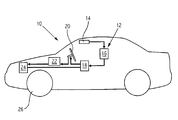
- an embodiment of the driver assistance device is in one Vehicle 10 shown, the driver assistance device Has image processing unit 12 with a video camera 14.
- the Image processing unit 12 includes, in addition to video camera 14 Computing unit 16, from those captured by the video camera 14 Lane data at least one characteristic value can be determined. Characteristic values can for example be: a yaw rate, a lateral deviation, a Lateral acceleration, a lateral speed, a float angle, a Change in the slip angle, a cross-deviation in foresight and / or a time-to-line crossing (TLC).
- the driver assistance device comprises Furthermore, a steering element control unit 18, which is connected to the computer unit 16 is connected that the at least one characteristic value to the Steering element control unit 18 can be transmitted.
- the Steering element control unit 18 designed from the at least one Characteristic value to determine a steering element angle change and one in the vehicle 10 existing steering wheel 20 according to the steering element angle change head for.
- the steering element control unit 18 in one alternative embodiment to be designed for control.
- a Steering torque detection unit 22 is from the driver onto the steering wheel 20 exerted steering torque can be detected.
- the detected steering torque is from the Steering torque detection unit 22 transmitted to a control element 24.
- Out the detected steering torque is a desired steering torque by the control element 24 determined that on the front wheels 26 of the vehicle 10 is transmitted.
- a target wheel angle can be determined, which then the front wheels 26 is transmitted.
- the resulting wheel angle can in turn be detected by the control element 24. This is the case designed that a target steering element angle from the detected wheel angle that can be determined via the steering element control unit 18 on the steering wheel 20 can be transferred.
- the target steering element angle can by Steering element control unit 18 can be modified if at least one certain characteristic value is present, which is a steering correction and thus a Requires a change in the steering element angle.
- the driver assistance device serves primarily to Drivers on motorways and country roads in the lateral guidance and the Support tracking. From the recorded course of the lane and thus also the detected respective position of the vehicle on the road therefore mainly determined characteristic values with transverse guidance and Tracking related. Particularly important parameters are under a cross-deviation in foresight or a time-to-line crossing (TLC).
- TLC time-to-line crossing
Abstract
Description
Die Erfindung betrifft eine Fahrerassistenzvorrichtung zur Assistenz eines Fahrers beim Fahren eines Fahrzeugs, wobei die Fahrerassistenzvorrichtung eine mit dem Fahrzeug mitgeführte Bildverarbeitungseinheit aufweist, durch die ein Verlauf einer mit dem Fahrzeug befahrenen Fahrbahn und damit auch eine jeweilige Position des Fahrzeugs auf der Fahrbahn erfaßbar ist, wobei aus den erfaßten Daten mindestens ein Kennwert ermittelbar ist, wobei die Fahrerassistenzvorrichtung weiterhin eine Lenkelementsteuereinheit aufweist, die dazu ausgelegt ist, aus dem mindestens einen Kennwert eine Sollgröße zu ermitteln und das Lenkelement entsprechend der Sollgröße anzusteuern. Die Erfindung betrifft auch ein entsprechendes Fahrerassistenzverfahren.The invention relates to a driver assistance device for assisting a driver Driver driving a vehicle, the driver assistance device has an image processing unit carried with the vehicle, through which a course of a lane used by the vehicle and thus also one respective position of the vehicle on the roadway can be detected, from the recorded data at least one characteristic value can be determined, the Driver assistance device further comprises a steering element control unit, which is designed to add a target value from the at least one characteristic value determine and control the steering element according to the target size. The The invention also relates to a corresponding driver assistance method.
Beispielsweise von BMW wird unter der Bezeichnung "Heading Control" ein Assistenzbaustein in Fahrzeuge integriert, der die Technik der Bildverarbeitung nutzt. Die "Heading Control" soll einen Fahrer bei einer querdynamischen Führung und Stabilisierung eines Fahrzeugs unterstützen. Dazu werden aus gewonnenen Bildverarbeitungsdaten die Fahrbahn bzw. der Fahrspurverlauf in Vorausschau sowie der Gierwinkelfehler und die seitliche Abweichung des Fahrzeugs in der Fahrspur ermittelt. Daraus werden verschiedene Kennwerte berechnet, wie z.B. die Querabweichung in Vorausschau oder die Time-to-Line-Crossing (TLC). In Abhängigkeit von diesen Kennwerten erhält der Fahrer synthetische Lenkmomente bzw. Lenkmomentänderungen, die ihn bei der Querführung unterstützen sollen. Wenn der Fahrer also die Toleranzgrenze des als optimal errechneten Lenkverhaltens überschreitet, spürt er am Lenkrad leichte Zusatzkräfte, mit denen die notwendigen Lenkkorrekturen angedeutet werden. Nachteilig ist jedoch, daß der Mensch Lenkmomentänderungen prinzipiell erst oberhalb einer Wahrnehmungsschwelle von ca. 0,5 Nm wahrnimmt, so daß durch Lenkmomentänderungen nur massive Lenkkorrekturen vermittelt werden können. Außerdem empfindet der Mensch Lenkmomente oberhalb von 3 - 5 Nm, die über eine längere Zeit wirken, als unangenehm und physisch beanspruchend.For example from BMW is called "Heading Control" Assistance module integrated in vehicles that uses the technology of image processing uses. The "Heading Control" is intended for a driver with a transverse dynamic Support the guidance and stabilization of a vehicle. To do this obtained image processing data the lane or the lane course in Foresight as well as the yaw angle error and the lateral deviation of the Vehicle determined in the lane. This results in various parameters calculated, e.g. the cross-deviation in foresight or the time-to-line crossing (TLC). The driver receives depending on these parameters Synthetic steering torques or changes in steering torque that the Should support lateral guidance. So if the driver has the tolerance limit of the steering behavior calculated as optimal, he feels on the steering wheel slight additional forces with which the necessary steering corrections are indicated become. The disadvantage, however, is that man changes the steering torque in principle only above a perception threshold of approx. 0.5 Nm perceives so that only massive changes in steering torque Steering corrections can be taught. In addition, man feels Steering torques above 3 - 5 Nm, which act over a longer period than uncomfortable and physically demanding.
Es ist daher Aufgabe der Erfindung, die gattungsgemäße Fahrerassistenzvorrichtung bzw. das gattungsgemäße Fahrerassistenzverfahren derart weiterzubilden, daß der Fahrer auch kleine Lenkkorrekturen wahrnehmen kann und auch über längere Zeit erfolgende Korrekturempfehlungen nicht als unangenehm empfindet.It is therefore an object of the invention, the generic Driver assistance device or the generic Develop driver assistance procedures in such a way that the driver also small Can perceive steering corrections and also over long periods of time Correction recommendations are not perceived as unpleasant.
Eine erste Lösung dieser Aufgabe stellt eine gattungsgemäße Fahrerassistenzvorrichtung dar, bei der die Sollgröße eine Lenkelementwinkeländerung ist. Im Gegensatz zum Stand der Technik ist bei der erfindungsgemäßen Fahrerassistenzvorrichtung eine Lenkelementsteuereinheit dazu ausgelegt, aus dem mindestens einen Kennwert eine Lenkelementwinkeländerung zu ermitteln und das Lenkelement entsprechend dieser Lenkelementwinkeländerung anzusteuern. Durch diese Lenkelementwinkeländerung erhält der Fahrer sehr viel direkter eine Information über den mindestens einen ermittelten Kennwert und die daraus resultierende Lenkkorrekturempfehlung, wobei auch eine verhältnismäßig kleine Lenkelementwinkeländerung, also nur eine geringfügige Lenkkorrekturempfehlung, durch den Fahrer leicht wahrgenommen werden kann. Durch die erfindungsgemäße Fahrerassistenzvorrichtung kann aufgrund der ebenfalls möglichen feinen Lenkkorrekturen eine bessere Querführung erreicht werden. Außerdem wird durch den Wegfall der Rückmeldung durch Änderung der Lenkmomente die physische Beanspruchung des Fahrers beim Lenken reduziert.A generic solution provides a first solution to this problem Driver assistance device in which the target size is a Steering element angle change is. In contrast to the prior art the driver assistance device according to the invention Steering element control unit designed from the at least one Characteristic value to determine a steering element angle change and the steering element to be controlled in accordance with this change in the steering element angle. Through this The driver receives a much more direct change in the steering element angle Information about the at least one determined characteristic value and the resulting one resulting steering correction recommendation, also a relative small steering element angle change, so only a minor one Steering correction recommendation that the driver can easily perceive can. Due to the driver assistance device according to the invention the also possible fine steering corrections a better lateral guidance can be achieved. In addition, through the elimination of the feedback Change the steering torque the physical stress of the driver when Steering reduced.
Dabei kann das Lenkelement durch die Lenkelementsteuereinheit entsprechend der Lenkelementwinkeländerung steuerbar oder regelbar sein.The steering element can be controlled by the steering element control unit be controllable or regulatable according to the change in the steering element angle.
Eine besonders vorteilhafte Weiterbildung der Erfindung sieht vor, daß die Bildverarbeitungseinheit eine Videokamera umfaßt. Idealerweise ist diese Videokamera im oberen Bereich der Frontscheibe angeordnet, so daß ein großer Bereich der Fahrbahn erfaßt werden kann. A particularly advantageous development of the invention provides that the Image processing unit comprises a video camera. Ideally this is Video camera arranged in the upper area of the windshield, so that a large area of the road can be covered.
Vorteilhafterweise kann in die Ermittlung des mindestens einen Kennwerts mindestens ein weiterer Betriebszustand des Fahrzeugs, insbesondere ein Radwinkel und/oder eine Fahrzeuggeschwindigkeit und/oder eine Giergeschwindigkeit, eingehen. Die genannten Größen können ohne Einsatz der Bildverarbeitungseinheit leicht ermittelt werden, da entsprechende Detektionssysteme in der Regel bereits im Fahrzeug vorhanden sind.The at least one characteristic value can advantageously be determined at least one further operating state of the vehicle, in particular one Wheel angle and / or a vehicle speed and / or a Yaw rate, go down. The sizes mentioned can be used without the image processing unit can be easily determined, since appropriate Detection systems are usually already in the vehicle.
Der mindestens eine Kennwert kann einen Gierwinkelfehler und/oder eine Giergeschwindigkeit und/oder eine Querabweichung und/oder eine Querbeschleunigung und/oder eine Quergeschwindigkeit und/oder einen Schwimmwinkel und/oder eine Schwimmwinkeländerung und/oder eine Querabweichung in Vorausschau und/oder eine Time-to-Line-Crossing (TLC) umfassen. Alle diese Zustandsgrößen können einzeln oder in Kombination miteinander in der Lenkelementwinkeländerung des Lenkelements berücksichtigt werden.The at least one characteristic value can be a yaw angle error and / or a Yaw rate and / or a lateral deviation and / or a Lateral acceleration and / or a transverse speed and / or a Float angle and / or a change in the float angle and / or a Cross-deviation in foresight and / or a time-to-line crossing (TLC) include. All of these state variables can be used individually or in combination with each other in the steering element angle change of the steering element be taken into account.
In einer weiteren vorteilhaften Ausgestaltung der Erfindung ist die Lenkelementsteuereinheit derart ausgebildet, daß eine Lenkelementbewegung durch den Fahrer des Fahrzeugs entgegen der Ansteuerung durch die Lenkelementsteuereinheit verhindert wird. Dies kann beispielsweise dadurch realisiert werden, daß die Lenkelementsteuereinheit ein elektrisch betriebenes Schneckengetriebe umfaßt, so daß der Fahrer den Lenkradwinkel nicht gegen dieses Schneckengetriebe aktiv verstellen kann. Auf diese Weise wird verhindert, daß der Fahrer das Lenkelement entgegen den Lenkempfehlungen bewegt.In a further advantageous embodiment of the invention, the Steering element control unit designed such that a steering element movement by the driver of the vehicle contrary to the control by the Steering element control unit is prevented. This can be done, for example be realized that the steering element control unit is an electrically operated Worm gear includes so that the driver does not oppose the steering wheel angle can actively adjust this worm gear. That way prevents the driver from using the steering element contrary to the steering recommendations emotional.
In einer weiteren vorteilhaften Ausgestaltung der Erfindung weist die Fahrerassistenzvorrichtung eine Lenkmomenterfassungseinheit zur Erfassung eines auf das Lenkelement vom Fahrer ausgeübten Lenkmoments auf. Folglich wird in dieser Ausgestaltung der Wille des Fahrers bzw. der Fahrerwunsch anhand der Krafteingabe am Lenkelement ermittelt. In a further advantageous embodiment of the invention, the Driver assistance device a steering torque detection unit for detection a steering torque exerted on the steering element by the driver. consequently in this embodiment, the driver's will or the driver's wish determined on the basis of the force input on the steering element.
Das erfaßte Lenkmoment kann dann auch in die Ermittlung des mindestens einen Kennwerts eingehen.The detected steering torque can then also be used to determine the minimum enter a characteristic value.
In einer weiteren Ausgestaltung der Erfindung ist das erfaßte Lenkmoment an ein Steuerelement übertragbar, wobei durch das Steuerelement aus dem Lenkmoment ein Soll-Lenkmoment oder ein Soll-Radwinkel ermittelbar ist, um dieses oder diesen auf Räder des Fahrzeugs zu übertragen. Folglich wird entsprechend des Fahrerwunschs ein Soll-Lenkmoment oder ein Soll-Radwinkel auf die Räder des Fahrzeugs übertragen.In a further embodiment of the invention, the detected steering torque is transferable to a control element, whereby by the control element from the Steering torque a target steering torque or a target wheel angle can be determined, to transfer this or these to wheels of the vehicle. Consequently a target steering torque or a target wheel angle according to the driver's request transferred to the wheels of the vehicle.
In einer weiteren besonders vorteilhaften Weiterbildung der Erfindung geht mindestens ein Kennwert in die Ermittlung des Soll-Lenkmoments oder des Soll-Radwinkels durch das Steuerelement ein. Auf diese Weise können die Räder nicht nur gemäß dem Fahrerwunsch, sondern auch in Abhängigkeit des mindestens einen Kennwerts eingestellt werden, so daß eine erhöhte Fahrsicherheit gegeben ist, weil die Räder automatisch so eingestellt werden, daß die Fahrspur gehalten wird.In a further particularly advantageous development of the invention at least one characteristic value in the determination of the target steering torque or the Target wheel angle by the control. That way they can Wheels not only according to the driver's request, but also depending on the at least one characteristic value can be set so that an increased Driving safety is given because the wheels are automatically set so that the lane is kept.
Eine weitere Ausgestaltung der Erfindung sieht vor, daß die Lenkelementsteuereinheit mit einem oder dem Steuerelement gekoppelt ist, wobei durch das Steuerelement aus einer ermittelten Radwinkelstellung ein Soll-Lenkelementwinkel ermittelbar ist, der von der Lenkelementsteuereinheit auf das Lenkelement übertragbar ist. Auf diese Weise erhält der Fahrer eine Rückmeldung über die Einstellung der Räder, die insbesondere durch das von ihm erzeugte Lenkmoment am Lenkelement verursacht wurde.Another embodiment of the invention provides that the Steering element control unit is coupled to one or the control element, wherein the control element from a determined wheel angle position Desired steering element angle can be determined by the steering element control unit is transferable to the steering element. In this way, the driver receives one Feedback on the adjustment of the wheels, in particular by the steering torque generated on the steering element was caused.
Vorteilhafterweise kann der Soll-Lenkelementwinkel durch die Lenkelementsteuereinheit entsprechend der aus dem mindestens einen Kennwert ermittelten Lenkelementwinkeländerung modifizierbar sein, wobei der modifizierte Soll-Lenkelementwinkel auf das Lenkelement übertragbar ist. Der Fahrer erhält damit gleichzeitig eine Rückmeldung über die Stellung der Räder und eine Lenkkorrekturempfehlung. The target steering element angle can advantageously be determined by the Steering element control unit corresponding to that from the at least one Characteristic value determined steering element angle change can be modified, wherein the modified target steering element angle is transferable to the steering element. The driver thus receives feedback on the position of the Wheels and a steering correction recommendation.
Eine zweite Lösung der obigen Aufgabe stellt ein Fahrerassistenzverfahren zur
Assistenz eines Fahrers beim Fahren eines Fahrzeugs dar, das folgende
Schritte umfaßt:
Außerdem können die bereits oben im Zusammenhang mit der erfindungsgemäßen Fahrerassistenzvorrichtung erwähnten Funktionen bei dem erfindungsgemäßen Fahrerassistenzverfahren vorgesehen sein.In addition, the above in connection with the Functions mentioned driver assistance device according to the invention the driver assistance method according to the invention may be provided.
Weitere Vorteile gehen aus den im folgenden unter Hinweis auf die Zeichnung beschriebenen Ausführungsbeispielen hervor.
- Die Figur
- zeigt eine Ausführungsform der erfindungsgemäßen Fahrerassistenzvorrichtung in einem Fahrzeug.
- The figure
- shows an embodiment of the driver assistance device according to the invention in a vehicle.
In der Figur ist eine Ausführungsform der Fahrerassistenzvorrichtung in einem
Fahrzeug 10 dargestellt, wobei die Fahrerassistenzvorrichtung eine
Bildverarbeitungseinheit 12 mit einer Videokamera 14 aufweist. Die
Bildverarbeitungseinheit 12 umfaßt neben der Videokamera 14 eine
Rechnereinheit 16, durch die aus den durch die Videokamera 14 erfaßten
Fahrbahndaten mindestens ein Kennwert ermittelbar ist. Kennwerte können
beispielsweise sein: eine Giergeschwindigkeit, eine Querabweichung, eine
Querbeschleunigung, eine Quergeschwindigkeit, ein Schwimmwinkel, eine
Schwimmwinkeländerung, eine Querabweichung in Vorausschau und/oder
eine Time-to-Line Crossing (TLC). Die Fahrerassistenzvorrichtung umfaßt
weiterhin eine Lenkelementsteuereinheit 18, die so mit der Rechnereinheit 16
verbunden ist, daß der mindestens eine Kennwert an die
Lenkelementsteuereinheit 18 übertragen werden kann. Weiterhin ist die
Lenkelementsteuereinheit 18 dazu ausgelegt, aus dem mindestens einen
Kennwert eine Lenkelementwinkeländerung zu ermitteln und ein im Fahrzeug
10 vorhandenes Lenkrad 20 entsprechend der Lenkelementwinkeländerung
anzusteuern. Obwohl unter Ansteuern in der vorliegenden Ausführungsform ein
Steuern zu verstehen ist, kann die Lenkelementsteuereinheit 18 in einer
alternativen Ausführungsform zum Regeln ausgelegt sein. Durch eine
Lenkmomenterfassungseinheit 22 ist ein vom Fahrer auf das Lenkrad 20
ausgeübtes Lenkmoment erfaßbar. Das erfaßte Lenkmoment wird von der
Lenkmomenterfassungseinheit 22 auf ein Steuerelement 24 übermittelt. Aus
dem erfaßten Lenkmoment wird durch das Steuerelement 24 ein Soll-Lenkmoment
ermittelt, das auf die Vorderräder 26 des Fahrzeugs 10
übertragen wird. In einer alternativen Ausführungsform geht in die Ermittlung
des Soll-Lenkmoments durch das Steuerelement 24 auch mindestens ein
Kennwert ein, der dem Steuerelement 24 durch die Lenkelementsteuereinheit
18 übermittelt wird. In einer weiteren alternativen Ausführungsform kann durch
das Steuerelement 24 auch ein Soll-Radwinkel ermittelt werden, der dann auf
die Vorderräder 26 übertragen wird. Der sich daraufhin einstellende Radwinkel
kann wiederum durch das Steuerelement 24 erfaßt werden. Dieses ist so
ausgelegt, daß aus dem erfaßten Radwinkel ein Soll-Lenkelementwinkel
ermittelbar ist, der über die Lenkelementsteuereinheit 18 auf das Lenkrad 20
übertragen werden kann. Der Soll-Lenkelementwinkel kann durch die
Lenkelementsteuereinheit 18 modifiziert werden, wenn hier mindestens ein
bestimmter Kennwert anliegt, der eine Lenkkorrektur und damit eine
Lenkelementwinkeländerung erforderlich macht.In the figure, an embodiment of the driver assistance device is in one
Die erfindungsgemäße Fahrerassistenzvorrichtung dient vor allem dazu, den Fahrer auf Autobahnen und Landstraßen bei der Querführung und der Spurhaltung zu unterstützen. Aus dem erfaßten Fahrbahnverlauf und damit auch der erfaßten jeweiligen Position des Fahrzeugs auf der Fahrbahn werden deshalb vor allem Kennwerte ermittelt, die mit der Querführung und Spurhaltung zusammenhängen. Besonders wichtige Kennwerte sind unter anderem eine Querabweichung in Vorausschau oder eine Time-to-Line-Crossing (TLC).The driver assistance device according to the invention serves primarily to Drivers on motorways and country roads in the lateral guidance and the Support tracking. From the recorded course of the lane and thus also the detected respective position of the vehicle on the road therefore mainly determined characteristic values with transverse guidance and Tracking related. Particularly important parameters are under a cross-deviation in foresight or a time-to-line crossing (TLC).
Weitere Veränderungen, Modifikationen oder Kombinationen der oben beschriebenen Ausführungsformen sind für den Fachmann offensichtlich und fallen ebenso unter den Schutzumfang der beigefügten Ansprüche.Further changes, modifications or combinations of the above Embodiments described are obvious to those skilled in the art also fall within the scope of the appended claims.
Claims (14)
dadurch gekennzeichnet, daß die Sollgröße eine Lenkelementwinkeländerung ist.Driver assistance device for assisting a driver when driving a vehicle, the driver assistance device having an image processing unit (12) carried along with the vehicle (10), through which a course of a roadway traveled by the vehicle (10) and thus also a respective position of the vehicle (10 ) can be detected on the road, at least one characteristic value being ascertainable from the recorded data, the driver assistance device further comprising a steering element control unit (18) which is designed to determine a target variable from the at least one characteristic value and the steering element (20) accordingly to control the target size,
characterized in that the setpoint is a change in steering element angle.
dadurch gekennzeichnet, daß das Lenkelement (20) durch die Lenkelementsteuereinheit (18) entsprechend der Lenkelementwinkeländerung steuerbar oder regelbar ist.Driver assistance device according to claim 1,
characterized in that the steering element (20) can be controlled or regulated by the steering element control unit (18) in accordance with the change in the steering element angle.
dadurch gekennzeichnet, daß die Bildverarbeitungseinheit (12) eine Videokamera (14) umfaßt.Driver assistance device according to one of the preceding claims,
characterized in that the image processing unit (12) comprises a video camera (14).
dadurch gekennzeichnet, daß in die Ermittlung des mindestens einen Kennwerts mindestens ein weiterer Betriebszustand des Fahrzeugs (10), insbesondere ein Radwinkel und/oder eine Fahrzeuggeschwindigkeit und/oder eine Giergeschwindigkeit, eingeht.Driver assistance device according to one of the preceding claims,
characterized in that at least one further operating state of the vehicle (10), in particular a wheel angle and / or a vehicle speed and / or a yaw rate, is included in the determination of the at least one characteristic value.
dadurch gekennzeichnet, daß der mindestens eine Kennwert einen Gierwinkelfehler und/oder eine Giergeschwindigkeit und/oder eine Querabweichung und/oder eine Querbeschleunigung und/oder eine Quergeschwindigkeit und/oder einen Schwimmwinkel und/oder eine Schwimmwinkeländerung und/oder eine Querabweichung in Vorausschau und/oder eine Time-to-Line Crossing (TLC) umfaßt.Driver assistance device according to one of the preceding claims,
characterized in that the at least one characteristic value includes a yaw angle error and / or a yaw rate and / or a lateral deviation and / or a lateral acceleration and / or a lateral speed and / or a slip angle and / or a slip angle change and / or a transverse deviation in foresight and / or includes a time-to-line crossing (TLC).
dadurch gekennzeichnet, daß die Lenkelementsteuereinheit (18) derart ausgebildet ist, daß eine Lenkelementbewegung durch den Fahrer des Fahrzeugs (10) entgegen der Ansteuerung durch die Lenkelementsteuereinheit (18) verhindert wird.Driver assistance device according to one of the preceding claims,
characterized in that the steering element control unit (18) is designed in such a way that a movement of the steering element by the driver of the vehicle (10) against the activation by the steering element control unit (18) is prevented.
dadurch gekennzeichnet, daß die Lenkelementsteuereinheit (18) ein elektrisch betriebenes Schneckengetriebe umfaßt.Driver assistance device according to claim 6,
characterized in that the steering element control unit (18) comprises an electrically operated worm gear.
dadurch gekennzeichnet, daß die Fahrerassistenzvorrichtung eine Lenkmomenterfassungseinheit (22) zur Erfassung eines auf das Lenkelement (20) von dem Fahrer ausgeübten Lenkmoments aufweist.Driver assistance device according to one of the preceding claims,
characterized in that the driver assistance device has a steering torque detection unit (22) for detecting a steering torque exerted on the steering element (20) by the driver.
dadurch gekennzeichnet, daß das erfaßte Lenkmoment in die Ermittlung des mindestens einen Kennwerts eingeht.Driver assistance device according to claim 8,
characterized in that the detected steering torque is included in the determination of the at least one characteristic value.
dadurch gekennzeichnet, daß das erfaßte Lenkmoment an ein Steuerelement (24) übertragbar ist, wobei durch das Steuerelement (24) aus dem Lenkmoment ein Soll-Lenkmoment oder ein Soll-Radwinkel ermittelbar ist, um dieses oder diesen auf Räder (26) des Fahrzeugs (10) zu übertragen. Driver assistance device according to one of claims 8 or 9,
characterized in that the detected steering torque can be transmitted to a control element (24), the control element (24) being able to determine a desired steering torque or a desired wheel angle from the steering torque in order to transmit this or these to wheels (26) of the vehicle ( 10) to transmit.
dadurch gekennzeichnet, daß mindestens ein Kennwert in die Ermittlung des Soll-Lenkmoments oder des Soll-Radwinkels durch das Steuerelement (24) eingeht.Driver assistance device according to claim 10,
characterized in that at least one characteristic value is included in the determination of the target steering torque or the target wheel angle by the control element (24).
dadurch gekennzeichnet, daß die Lenkelementsteuereinheit (18) mit einem Steuerelement (24) gekoppelt ist, wobei durch ein oder das Steuerelement (24) aus einer ermittelten Radwinkelstellung ein Soll-Lenkelementwinkel ermittelbar ist, der von der Lenkelementsteuereinheit (18) auf das Lenkelement (20) übertragbar ist.Driver assistance device according to one of the preceding claims,
characterized in that the steering element control unit (18) is coupled to a control element (24), wherein a target steering element angle can be determined by one or the control element (24) from a determined wheel angle position, which angle is directed from the steering element control unit (18) to the steering element (20 ) is transferable.
dadurch gekennzeichnet, daß der Soll-Lenkelementwinkel durch die Lenkelementsteuereinheit (18) entsprechend der aus dem mindestens einen Kennwert ermittelten Lenkelementwinkeländerung modifizierbar ist, wobei der modifizierte Soll-Lenkelementwinkel auf das Lenkelement (20) übertragbar ist.Driver assistance device according to claim 12,
characterized in that the target steering element angle can be modified by the steering element control unit (18) in accordance with the change in the steering element angle determined from the at least one characteristic value, the modified target steering element angle being transferable to the steering element (20).
Applications Claiming Priority (2)
| Application Number | Priority Date | Filing Date | Title |
|---|---|---|---|
| DE10111283 | 2001-03-09 | ||
| DE10111283A DE10111283A1 (en) | 2001-03-09 | 2001-03-09 | Driver assistance device and driver assistance method for assisting a driver when driving a vehicle |
Publications (3)
| Publication Number | Publication Date |
|---|---|
| EP1239355A2 true EP1239355A2 (en) | 2002-09-11 |
| EP1239355A3 EP1239355A3 (en) | 2004-03-17 |
| EP1239355B1 EP1239355B1 (en) | 2006-12-13 |
Family
ID=7676804
Family Applications (1)
| Application Number | Title | Priority Date | Filing Date |
|---|---|---|---|
| EP02004600A Expired - Lifetime EP1239355B1 (en) | 2001-03-09 | 2002-02-28 | Method and device for assisting a driver of a vehicle |
Country Status (2)
| Country | Link |
|---|---|
| EP (1) | EP1239355B1 (en) |
| DE (2) | DE10111283A1 (en) |
Cited By (2)
| Publication number | Priority date | Publication date | Assignee | Title |
|---|---|---|---|---|
| EP1588910A1 (en) * | 2004-04-23 | 2005-10-26 | Audi Ag | Method for vehicle dynamics analysis and vehicle dynamics control as well as vehicle for carrying out the method |
| EP2251244A3 (en) * | 2009-05-15 | 2014-07-09 | ZF Lenksysteme GmbH | Method for operating the steering system in a vehicle |
Families Citing this family (4)
| Publication number | Priority date | Publication date | Assignee | Title |
|---|---|---|---|---|
| DE10251949A1 (en) | 2002-11-08 | 2004-05-19 | Robert Bosch Gmbh | Driving dynamics regulation method in motor vehicle, involves image sensor system generating image information from vehicle's surroundings using stereo camera |
| DE10254525A1 (en) * | 2002-11-22 | 2004-06-17 | Audi Ag | Method and device for predicting vehicle behavior and related computer program product |
| DE10352955A1 (en) * | 2003-11-13 | 2005-06-23 | Audi Ag | Driver assistance system to assist the tracking of a motor vehicle and apparatus for operating the driver assistance system |
| DE102007016799B4 (en) * | 2007-04-05 | 2009-03-19 | Deutsches Zentrum für Luft- und Raumfahrt e.V. | Driver assistance system, steering and method for assisting the driver of a vehicle |
Citations (1)
| Publication number | Priority date | Publication date | Assignee | Title |
|---|---|---|---|---|
| US5765116A (en) * | 1993-08-28 | 1998-06-09 | Lucas Industries Public Limited Company | Driver assistance system for a vehicle |
Family Cites Families (6)
| Publication number | Priority date | Publication date | Assignee | Title |
|---|---|---|---|---|
| DE3830747A1 (en) * | 1988-09-09 | 1990-03-22 | Freund Eckhard | METHOD AND DEVICE FOR AUTOMATICALLY GUIDING THE LONGITUDINAL AND LATERAL MOVEMENTS OF A VEHICLE |
| DE4407757A1 (en) * | 1993-03-08 | 1994-09-15 | Mazda Motor | Device for detecting obstacles for a vehicle |
| DE4332836C1 (en) * | 1993-09-27 | 1994-09-15 | Daimler Benz Ag | Device for steering a vehicle with controlled tracking |
| JP3574235B2 (en) * | 1995-08-31 | 2004-10-06 | 本田技研工業株式会社 | Vehicle steering force correction device |
| JP3367355B2 (en) * | 1996-11-26 | 2003-01-14 | トヨタ自動車株式会社 | Vehicle steering control device |
| JP3430832B2 (en) * | 1997-01-27 | 2003-07-28 | 日産自動車株式会社 | Road curvature estimator |
-
2001
- 2001-03-09 DE DE10111283A patent/DE10111283A1/en not_active Withdrawn
-
2002
- 2002-02-28 DE DE50208921T patent/DE50208921D1/en not_active Expired - Lifetime
- 2002-02-28 EP EP02004600A patent/EP1239355B1/en not_active Expired - Lifetime
Patent Citations (1)
| Publication number | Priority date | Publication date | Assignee | Title |
|---|---|---|---|---|
| US5765116A (en) * | 1993-08-28 | 1998-06-09 | Lucas Industries Public Limited Company | Driver assistance system for a vehicle |
Cited By (2)
| Publication number | Priority date | Publication date | Assignee | Title |
|---|---|---|---|---|
| EP1588910A1 (en) * | 2004-04-23 | 2005-10-26 | Audi Ag | Method for vehicle dynamics analysis and vehicle dynamics control as well as vehicle for carrying out the method |
| EP2251244A3 (en) * | 2009-05-15 | 2014-07-09 | ZF Lenksysteme GmbH | Method for operating the steering system in a vehicle |
Also Published As
| Publication number | Publication date |
|---|---|
| EP1239355A3 (en) | 2004-03-17 |
| DE10111283A1 (en) | 2002-09-19 |
| DE50208921D1 (en) | 2007-01-25 |
| EP1239355B1 (en) | 2006-12-13 |
Similar Documents
| Publication | Publication Date | Title |
|---|---|---|
| DE102008057313B4 (en) | Method and device for determining a corrective steering torque | |
| DE4332836C1 (en) | Device for steering a vehicle with controlled tracking | |
| EP2155534B1 (en) | Driver assistance device and method for the control thereof | |
| DE102007048512B4 (en) | Vehicle steering control device and vehicle steering control method | |
| DE102006058413B4 (en) | A method for displaying an operating state of a driver assistance system and driver assistance system with a display device for carrying out the method | |
| EP2152565B1 (en) | Method and device for the control of a driver assistance system | |
| EP2915723A2 (en) | Method for operating a steering system, steering system and vehicle | |
| EP1767437A1 (en) | Steering-pull compensation device for motor vehicle | |
| DE102019135047A1 (en) | Steer-by-wire steering system, method for operating a steer-by-wire steering system and vehicle | |
| DE102015005975B4 (en) | Method for operating a transverse guidance system of a motor vehicle and motor vehicle | |
| DE102008008182B4 (en) | Motor vehicle and method for operating a motor vehicle | |
| DE102019214225A1 (en) | Method for operating a vehicle with dynamic change of a usable wheel steering angle adjustment range | |
| DE102019216908A1 (en) | Method and device for generating a warning signal on the steering wheel of a vehicle | |
| WO2019206376A1 (en) | Activation of a driving function for automated driving with longitudinal and transverse guidance via a different driving function for automated driving with a low degree of automation | |
| EP1239355B1 (en) | Method and device for assisting a driver of a vehicle | |
| DE102017223288A1 (en) | Method for operating a steer-by-wire steering system for a motor vehicle and steering system for a motor vehicle | |
| DE102017211859A1 (en) | Multifunctional steering column, motor vehicle and method for operating a motor vehicle | |
| DE102018119268B4 (en) | Rack force optimized steering feel of a steer-by-wire motor vehicle steering system | |
| DE102019134568A1 (en) | Method for operating a power steering system of a vehicle, power steering system and vehicle | |
| DE102018132865A1 (en) | Method for determining a steering feel of a steer-by-wire steering system | |
| DE10109085A1 (en) | Method and computer program for operating a vehicle steering, control and / or regulating device for vehicle steering and vehicle steering | |
| DE102018204965B3 (en) | Method, control unit and steering system for determining the value of a steering intervention variable in a motor vehicle | |
| DE102012019235B4 (en) | Method and device for lateral control of a vehicle | |
| DE102017008427B4 (en) | Device and method for controlling a rear wheel steering | |
| DE102007043913B4 (en) | Method for controlling a driver assistance system |
Legal Events
| Date | Code | Title | Description |
|---|---|---|---|
| PUAI | Public reference made under article 153(3) epc to a published international application that has entered the european phase |
Free format text: ORIGINAL CODE: 0009012 |
|
| AK | Designated contracting states |
Kind code of ref document: A2 Designated state(s): AT BE CH CY DE DK ES FI FR GB GR IE IT LI LU MC NL PT SE TR |
|
| AX | Request for extension of the european patent |
Free format text: AL;LT;LV;MK;RO;SI |
|
| PUAL | Search report despatched |
Free format text: ORIGINAL CODE: 0009013 |
|
| AK | Designated contracting states |
Kind code of ref document: A3 Designated state(s): AT BE CH CY DE DK ES FI FR GB GR IE IT LI LU MC NL PT SE TR |
|
| AX | Request for extension of the european patent |
Extension state: AL LT LV MK RO SI |
|
| 17P | Request for examination filed |
Effective date: 20040312 |
|
| AKX | Designation fees paid |
Designated state(s): DE FR GB IT |
|
| 17Q | First examination report despatched |
Effective date: 20041221 |
|
| GRAP | Despatch of communication of intention to grant a patent |
Free format text: ORIGINAL CODE: EPIDOSNIGR1 |
|
| GRAS | Grant fee paid |
Free format text: ORIGINAL CODE: EPIDOSNIGR3 |
|
| GRAA | (expected) grant |
Free format text: ORIGINAL CODE: 0009210 |
|
| AK | Designated contracting states |
Kind code of ref document: B1 Designated state(s): DE FR GB IT |
|
| PG25 | Lapsed in a contracting state [announced via postgrant information from national office to epo] |
Ref country code: IT Free format text: LAPSE BECAUSE OF FAILURE TO SUBMIT A TRANSLATION OF THE DESCRIPTION OR TO PAY THE FEE WITHIN THE PRESCRIBED TIME-LIMIT;WARNING: LAPSES OF ITALIAN PATENTS WITH EFFECTIVE DATE BEFORE 2007 MAY HAVE OCCURRED AT ANY TIME BEFORE 2007. THE CORRECT EFFECTIVE DATE MAY BE DIFFERENT FROM THE ONE RECORDED. Effective date: 20061213 |
|
| REG | Reference to a national code |
Ref country code: GB Ref legal event code: FG4D Free format text: NOT ENGLISH |
|
| REF | Corresponds to: |
Ref document number: 50208921 Country of ref document: DE Date of ref document: 20070125 Kind code of ref document: P |
|
| GBT | Gb: translation of ep patent filed (gb section 77(6)(a)/1977) |
Effective date: 20070208 |
|
| ET | Fr: translation filed | ||
| PLBE | No opposition filed within time limit |
Free format text: ORIGINAL CODE: 0009261 |
|
| STAA | Information on the status of an ep patent application or granted ep patent |
Free format text: STATUS: NO OPPOSITION FILED WITHIN TIME LIMIT |
|
| 26N | No opposition filed |
Effective date: 20070914 |
|
| REG | Reference to a national code |
Ref country code: FR Ref legal event code: PLFP Year of fee payment: 15 |
|
| REG | Reference to a national code |
Ref country code: FR Ref legal event code: PLFP Year of fee payment: 16 |
|
| REG | Reference to a national code |
Ref country code: FR Ref legal event code: PLFP Year of fee payment: 17 |
|
| PGFP | Annual fee paid to national office [announced via postgrant information from national office to epo] |
Ref country code: FR Payment date: 20210223 Year of fee payment: 20 Ref country code: IT Payment date: 20210226 Year of fee payment: 20 |
|
| PGFP | Annual fee paid to national office [announced via postgrant information from national office to epo] |
Ref country code: DE Payment date: 20210228 Year of fee payment: 20 Ref country code: GB Payment date: 20210219 Year of fee payment: 20 |
|
| REG | Reference to a national code |
Ref country code: DE Ref legal event code: R071 Ref document number: 50208921 Country of ref document: DE |
|
| REG | Reference to a national code |
Ref country code: GB Ref legal event code: PE20 Expiry date: 20220227 |
|
| PG25 | Lapsed in a contracting state [announced via postgrant information from national office to epo] |
Ref country code: GB Free format text: LAPSE BECAUSE OF EXPIRATION OF PROTECTION Effective date: 20220227 |